punjab state e-governance society · 1 punjab state e-governance society government of punjab,...
TRANSCRIPT
1
PUNJAB STATE E-GOVERNANCE SOCIETY
GOVERNMENT OF PUNJAB, CHANDIGARH
REQUEST FOR PROPOSAL - VOLUME II
FOR
SELECTION OF DATA CENTRE OPERATOR (DCO)
TO ESTABLISH STATE DATA CENTRE IN PUNJAB
UNDER NATIONAL E-GOVERNANCE PLAN
Ref No: SDC/Punjab/DGR/PSeGS/2013/01
Punjab State e-Governance Society O/o Department of Governance Reforms
SCO 193-195, Sector 34-A, Chandigarh
2
Table of Contents
ANNEXURES ............................................................................................................................................................... 5
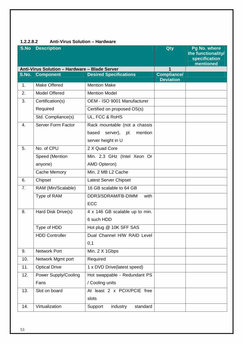
1.1 Annexure I – Technical Requirements ................................................................................... 5 1.1.1 Current Scenario ................................................................................................................. 5 1.1.1.1. Infrastructure ...................................................................................................................... 5 1.1.2 Server and Application Set-up at SDC ................................................................................... 5 1.1.2.1 Web Servers ....................................................................................................................... 6 1.1.2.2 Application Servers .............................................................................................................. 6 1.1.2.3 Database Server .................................................................................................................. 6 1.1.2.4 Staging Server..................................................................................................................... 6 1.1.2.5 Backup Server ..................................................................................................................... 6 1.1.2.6 Directory Server (Enterprise Access Server) .......................................................................... 6 1.1.2.7 Proxy Server ....................................................................................................................... 7 1.1.2.8 DNS/ DHCP Servers ............................................................................................................. 7 1.1.2.9 Load Balancer ..................................................................................................................... 7 1.1.2.10 Intrusion Detection Server ................................................................................................... 7 1.1.2.11 Management Server ............................................................................................................ 7 1.1.2.12 Helpdesk System ................................................................................................................. 8 1.1.3 SDC Platform and Storage Architecture ................................................................................. 9 1.1.4 SDC Network and Security Architecture ............................................................................... 11 1.2 Annexure II – Technical Specifications – IT components ...................................................... 13 1.2.1 Application IT component – Application infrastructure .......................................................... 13 1.2.1.1 Application identified for Acceptance and Testing ................................................................ 13 1.2.2 Technical Specifications – Platform and Storage .................................................................. 13 1.2.2.1 Blade Chassis/ Enclosure .................................................................................................... 15 1.2.2.2 Application Web Server (Quantity – 5) ................................................................................ 16 1.2.2.2.1 Hardware specification of x64 Architecture (Quantity – 3) .................................................... 16 1.2.2.2.2 Hardware specification of RISC/EPIC Architecture (Quantity – 2) .......................................... 18 1.2.2.2.3 Software for Web Server .................................................................................................... 20 1.2.2.3 Application Server (Quantity - 5) ........................................................................................ 21 1.2.2.3.1 Hardware specification of x64 Architecture (Quantity – 3) .................................................... 21 1.2.2.3.2 Hardware specification of RISC/EPIC Architecture (Quantity – 2) .......................................... 23 1.2.2.3.3 Software for Application Server (Blade) ............................................................................... 24 1.2.2.4 Database Server (Quantity – 3) .......................................................................................... 26 1.2.2.4.1 Hardware specification of x64 Architecture (Quantity – 3) .................................................... 26 1.2.2.4.2 Software for Database Server ............................................................................................. 28 1.2.2.5 Staging Server................................................................................................................... 29 1.2.2.5.1 Hardware specification (Quantity – 1) ................................................................................. 29 1.2.2.5.2 Software for Staging Server ............................................................................................... 31 1.2.2.6 Storage and Backup Solution .............................................................................................. 32 1.2.2.6.1 Storage Hardware specification (Quantity – 1)..................................................................... 32 1.2.2.6.2 Backup Solution................................................................................................................. 35 1.2.2.6.3 Backup Software ............................................................................................................... 37 1.2.2.6.4 Backup Server Hardware .................................................................................................... 39 1.2.2.6.5 OS Software for Backup Server .......................................................................................... 41 1.2.2.6.6 SAN Switch (Quantity – 2) ................................................................................................. 42 1.2.2.7 Directory Services .............................................................................................................. 44 1.2.2.7.1 Directory Service – Software .............................................................................................. 44 1.2.2.7.2 DNS, DHCP - Software specifications : ................................................................................ 45 1.2.2.7.3 Directory Service, DNS, DHCP – Hardware (Blade)............................................................... 47 1.2.2.7.4 Operating System Software for Directory Service, DNS and DHCP ........................................ 49 1.2.2.8 Anti-Virus Solution (with 50 user licenses) ........................................................................... 50 1.2.2.8.1 Antivirus Software specifications ......................................................................................... 50 1.2.2.8.2 Anti-Virus Solution – Hardware ........................................................................................... 53 1.2.2.8.3 OS Software Licenses for Antivirus Servers.......................................................................... 55
3
1.2.2.9 Management Solution ........................................................................................................ 56 1.2.2.9.1 Management Solution - Software Specification .................................................................... 56 1.2.2.9.2 Management Servers – Hardware ....................................................................................... 56 1.2.2.9.3 Software Licenses for Management Servers ........................................................................ 58 1.2.2.10 IP KVM ............................................................................................................................. 59 1.2.3 Technical Specifications – IT Network Components .............................................................. 61 1.2.3.1 LAN Switch – Core ............................................................................................................. 62 1.2.3.2 LAN Switch – Access .......................................................................................................... 65 1.2.3.3 INTERNET Router .............................................................................................................. 67 1.2.3.4 Firewall Internet ................................................................................................................ 71 1.2.3.5 Intrusion Prevention System - Internet ............................................................................... 73 1.2.3.6 End Point Protection for Servers and PCs (HIDS/ HIPS)........................................................ 77 1.2.3.7 Server Load Balancer (Qty: 1+1) ........................................................................................ 81 1.2.3.8 Authentication, Authorization and Accounting (Qty: 1) ......................................................... 83 1.2.4 SDC EMS Architecture ........................................................................................................ 85 1.2.4.1 Technical Specifications - EMS ............................................................................................ 97 1.2.4.1.1 Hardware Specification (Quantity – Minimum 3 Servers) ...................................................... 97 1.2.5 Functional requirement for Disaster Recovery Management Software ................................... 98 1.2.6 Functional requirement Specification for Cloud ................................................................... 101 1.2.6.1 General Requirment .......................................................................................................... 101 1.2.6.2 Functional Requirment Specification(FRS) for Cloud Enablement ......................................... 102 1.2.7 Security Components ........................................................................................................ 112 1.3 SDC Architecture – Physical Infrastructure ......................................................................... 116 1.3.1.1 Layout of Data Centre ....................................................................................................... 116 1.3.1.2 Technical Specifications – Civil and Interior Work ............................................................... 117 1.3.1.2.1 Modes of Measurement ..................................................................................................... 122 1.3.1.3 Technical Specifications – Electrical ................................................................................... 124 1.3.1.3.1 UPS, Batteries and Accessories .......................................................................................... 124 1.3.1.4 Technical Specification – Diesel Generating Sets ................................................................. 140 1.3.1.5 Technical Specifications – Electrical: Low Side .................................................................... 158 1.3.1.6 Technical Specifications – Supply And Installation Of Low Voltage Cables ............................ 177 1.3.1.7 Technical Specifications: Low Voltage Systems ................................................................... 180 1.3.1.8 Technical Specifications – Light Fixtures............................................................................. 190 1.3.1.9 Technical Specification - Earthing System........................................................................... 191 1.3.1.10 Technical Specifications – Change Over Switch for PAC ....................................................... 194 1.3.1.11 Technical Specifications – Air Conditioning ......................................................................... 195 1.3.1.11.1 Precision Air Conditioning .................................................................................................. 195 1.3.1.11.2 Technical Specifications – Comfort AC ................................................................................ 198 1.3.1.12 Technical Specification – Integrated Building Management System ...................................... 200 1.3.1.13 Technical Specification – Addressable Fire Alarm System .................................................... 236 1.3.1.14 Access ControlSystem ....................................................................................................... 261 1.3.1.15 Surveillance CCTV System ................................................................................................. 269 1.3.1.16 NOVEC1230 OR INERGEN GAS BASED FIRE SUPPRESSION SYSTEM .................................... 274 1.3.1.17 Rodent Repellant System .................................................................................................. 276 1.3.1.18 Smoke detection Syste ...................................................................................................... 277 1.3.1.19 Water Leak Detection System ............................................................................................ 287 1.3.1.20 Technical Specification – Passive Networking ..................................................................... 290 1.3.2 Bill of Quantity – Physical Quantity Civil and Interiors ......................................................... 296 1.3.2.1 Bill of Quantity: Electrical System ...................................................................................... 310 1.3.2.2 Bill of Quantity: Air Conditioning System ............................................................................ 325 1.3.2.3 Bill of Quantity: Safety and Security Systems ..................................................................... 330 1.3.2.4 Bill of Quantity: Passive Networking ................................................................................... 339 1.3.3 Bill Of Quantity: Networking Components .......................................................................... 342 1.3.4 Bill Of Quantity: Management, Monitoring & Helpdesk SYSTEM (EMS) ................................. 343 1.3.5 Bill Of Quantity: Platform and Storage ............................................................................... 344 1.3.6 Bill of Quantity: Software Licenses ..................................................................................... 346 1.3.7 Bill of Quantity : Additional Component .............................................................................. 350

4
1.4 Annexure II: Indicative Proposed SDC Layout .................................................................... 351 1.5 Indication Layout plan for Main Sub-station and DG station ................................................. 352 1.6 Annexure III : Single Line Diagram (Electrical) - Tentative .................................................. 353 1.7 Annexure IV: Load Calculation Sheet ................................................................................. 354
5
Annexures
1.1 Annexure I – Technical Requirements
1.1.1 Current Scenario
Punjab SWAN and SDC are proposed to be co-located. Punjab state is going for a new state
data center to host all the upcoming applications.
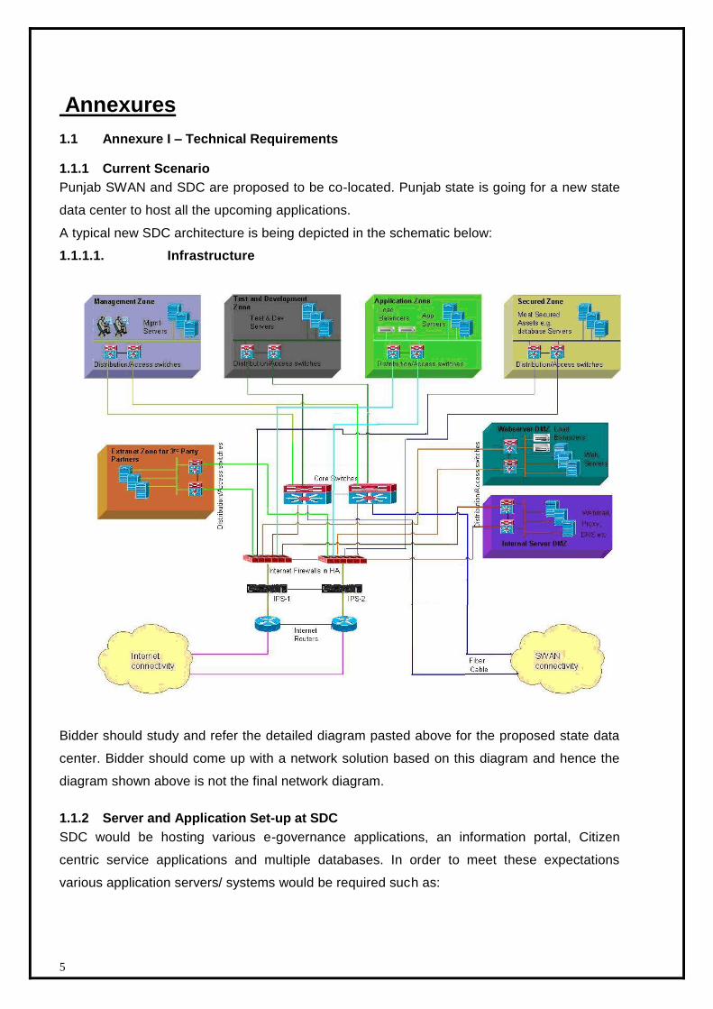
A typical new SDC architecture is being depicted in the schematic below:
1.1.1.1. Infrastructure
Bidder should study and refer the detailed diagram pasted above for the proposed state data
center. Bidder should come up with a network solution based on this diagram and hence the
diagram shown above is not the final network diagram.
1.1.2 Server and Application Set-up at SDC
SDC would be hosting various e-governance applications, an information portal, Citizen
centric service applications and multiple databases. In order to meet these expectations
various application servers/ systems would be required such as:
6
1.1.2.1 Web Servers
Web based applications are easily accessible from any sort of the network, Intranet, internet or
extranet. Therefore, Web server plays a vital role in SDC. Most of the new application are having
web interface, which requires web servers for such services. The web servers would also be
used for web hosting for different department
1.1.2.2 Application Servers
Application would be required as middle tier for various web based applications. Application
server would take care of the necessary workflow and web server would be required for the
interfacing with the end user. Both the web and application server would be seamlessly
integrated to provide high availability and performance. It is proposed to have two separate
applications solutions for Unix/ Linux and Windows environment.
1.1.2.3 Database Server
The database/ repository provides all the relevant information required to process any Citizen/
Government request or to render any e-Governance services with the use of SDC. Database
server would be required to store and access data with ease. This would also be integrated with
multiple applications, residing at SDC. Database servers should be configured in highly available
mode.
1.1.2.4 Staging Server
It would be required to deploy a separate server as Staging server where all the new services
are deployed before it is brought on to the production servers.
1.1.2.5 Backup Server
Backup server would be used for backing up the data at regular interval. The backing up of
the data would be an automated process. Whenever desired the backed up data
can be restored retrieved to the desired system configuration.
1.1.2.6 Directory Server (Enterprise Access Server)
Using Directory services SDC administrator should be able to define centralized authentication &
authorization mechanisms for users. This would enable associate policies such as security,
management etc on all servers/ systems from a centralized console and enhances security,
reduces IT complexity and increase overall efficiency. It should be LDAP v3 compliant, in order to
have integrated interoperability, security & manageability. It would also enable central
authentication thus enabling single sign-on (SSO) mechanism. Therefore this user directory
would enable easy manageability that is creation, modification and deletion of user records. It
would further help to integrate with various other services like messaging, proxy, etc. The
directory services should also be able to cater the requirements of the State for client
7
workstations also.
1.1.2.7 Proxy Server
Proxy Server will be used in neighborhood of one or more web servers, all the traffic from
internet destined to one or more web server goes through proxy server. Proxy server will also be
configured in SDC to enforce internet access policy and caching of static contents.
1.1.2.8 DNS/ DHCP Servers
DNS server would be required for various website and web application hosted for public/ Govt.
access. The internet users will query for the domains on the DNS (Public DNS) server deployed
at the SDC. DHCP would be assisting the System administrators for dynamic IP allocation to
devices/ users. Furthermore, the key users (require SDC services), who would be connecting
using remote access, would be requiring a valid IP address after successful authentication.
1.1.2.9 Load Balancer
The load balancer would be required for distributing workloads to a set of networked computer
servers in such a manner that the computing resources are used in an optimal manner. The
load balancer should support segmentation to distribute load for multiple services, servers.
This would increase the availability of the server and should also increase the performance as
multiple servers would be sharing the service load. The load balancer would be used for the
following servers:
Application Server
Web Servers
Database Servers
Integartion Servers
1.1.2.10 Intrusion Detection Server
Any attempts of intrusion over a network should be detected and logged into a database,
which should form the basis of reports generated. This would provide proactive information
while the network is being compromised based on certain network patterns detected.
1.1.2.11 Management Server
The management server would help in administration of distributed systems at SDC. The
management server would help in efficient and reliable administration of all the distributed
computing devices and enable:
Inventory Management
Patch management
Monitor the availability of Services
8
Fault Management
Performance Management
1.1.2.12 Helpdesk System
An ITIL based Helpdesk system would be used for assisting the service delivery by DCO for
SDC. Helpdesk system would automatically generate the incident tickets and log the call. Such
calls are forwarded to the desired system support personnel deputed by the DCO. These
personnel would look into the problem, diagnose and isolate such faults and resolve the issues
timely. The helpdesk system would be having necessary workflow for transparent, smoother and
cordial SDC support framework.
Provide flexibility of logging incident manually via windows GUI and web interface.
The web interface console of the incident tracking system would allow viewing, updating and
closing of incident tickets.
System should provide Knowledge base
Provide seamless integration to events/incident automatically from NMS / EMS.
Allow categorization on the type of incident being logged.
Provide classification to differentiate the criticality of the incident via the priority levels,
severity levels and impact levels.
Each incident could be able to associate multiple activity logs entries manually or
automatically events / incidents from other security tools or EMS / NMS.
Provide audit logs and reports to track the updating of each incident ticket.
Proposed incident tracking system would be ITIL compliant.
It should integrate with Enterprise Management System event management and
support automatic problem registration, based on predefined policies.
It should be able to log and escalate user interactions and requests.
It should provide status of registered calls to end-users over email and through web.
9
1.1.3 SDC Platform and Storage Architecture
This section of the RFP outlines platform and storage components to be deployed as part of
SDC project. Majority of e-Governance applications are developed for Windows and Unix
Operating System on x86 and RISC/ EPIC hardware platform. Server farm will be comprised
of hardware for Directory service, Proxy Service, Antivirus service, DNS and DHCP Service,
Backup service and Server for Enterprise Management suite. Other IT components appear
under Optional components section as part of SDC deployment is subject to Punjab State
decision. Apart from the core infrastructure components listed above, hardware has to be
proposed for the three tier application architecture viz. Front end web server, application
server and Database server.
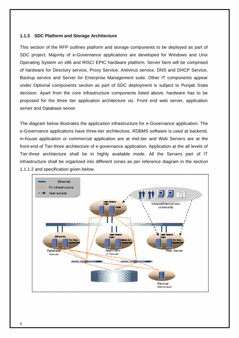
The diagram below illustrates the application infrastructure for e-Governance application. The
e-Governance applications have three-tier architecture, RDBMS software is used at backend,
in-house application or commercial application are at mid-tier and Web Servers are at the
front-end of Tier-three architecture of e-governance application. Application at the all levels of
Tier-three architecture shall be in highly available mode. All the Servers part of IT
infrastructure shall be organized into different zones as per reference diagram in the section
1.1.1.2 and specification given below.

10
DNS/DHCP should be in highly available mode with primary and secondary servers. There should be
two different views or servers for public and private DNS services.
There should be at least one primary and one secondary Directory server configured in such a way
that directory services are available 100% of the time
There should be a redundancy at DNS and DHCP level which can be on a load balanced or Primary
Secondary mode. Two separate instances of DNS have to be created with two different views. The
two instances are for internal (Intranet) and external (Internet) usage. The external instance view is
only available to external (internet) users and the internal view is only available to internal/ intranet
servers. Separate view has been created for external lookups. Domain name would be same for
external and internal usage.
Web servers facing external world should be placed in DMZ internet zone in load balanced mode
using external load balancer.
All Database servers should be placed in secured zone in highly available configuration.
Application servers which provides business logic and work flow should be placed in secured zone in
high available mode
Server and Network/ Security Management servers should be located in management zone
Staging servers are used for development, testing and pre-production activities should be located in
separate test and development zone
All the proposed servers should be configured with 32/ 64 bit Enterprise operating system.
Since, Consolidation and is a trend and requirements of any upcoming Data Center, Vendors are
encouraged to design the solution to meet Consolidation requirement of Data Center.
State Government intends to host all state government applications pertaining to various divisions
and departments in a single location with commitment of better service and availability to end users,
it is imperative that availability of the proposed solution should be high by design. Bidders should
establish in his technical proposal, how the same is proposed from a stand alone component level as
well as an overall solution level.
Bidders shall propose changes to design to value add, if applicable.
Bidder shall supply all end-to-end components for LAN / SAN connectivity of servers and Storage.
Bidder may propose alternative solutions (other than BOM proposed in RFP) inline with the
standards, guidelines provided in the RFP and to meet SDC objectives and SLA’s.
The Servers need to be stateless to support network virtualization as part of the cloud for the servers.
11
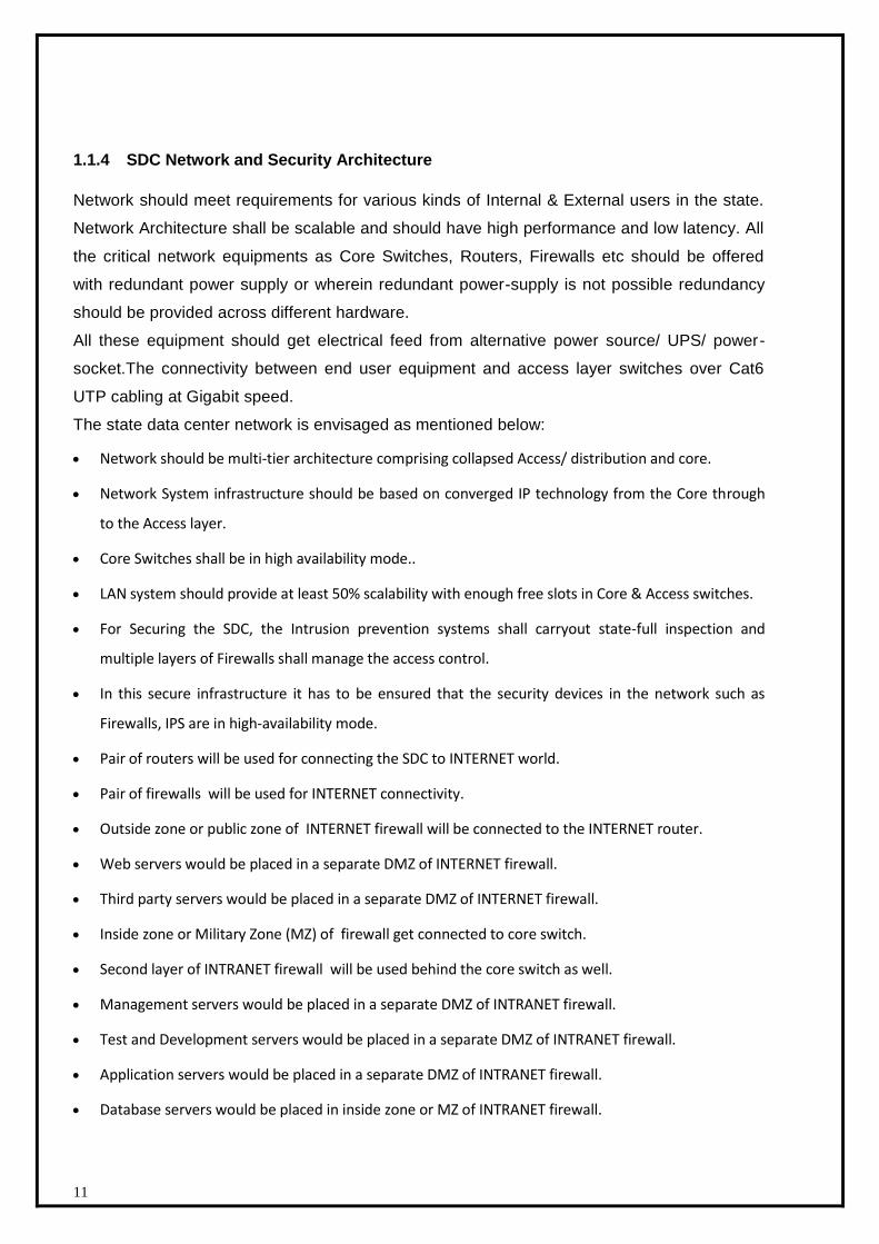
1.1.4 SDC Network and Security Architecture
Network should meet requirements for various kinds of Internal & External users in the state.
Network Architecture shall be scalable and should have high performance and low latency. All
the critical network equipments as Core Switches, Routers, Firewalls etc should be offered
with redundant power supply or wherein redundant power-supply is not possible redundancy
should be provided across different hardware.
All these equipment should get electrical feed from alternative power source/ UPS/ power-
socket.The connectivity between end user equipment and access layer switches over Cat6
UTP cabling at Gigabit speed.
The state data center network is envisaged as mentioned below:
Network should be multi-tier architecture comprising collapsed Access/ distribution and core.
Network System infrastructure should be based on converged IP technology from the Core through
to the Access layer.
Core Switches shall be in high availability mode..
LAN system should provide at least 50% scalability with enough free slots in Core & Access switches.
For Securing the SDC, the Intrusion prevention systems shall carryout state-full inspection and
multiple layers of Firewalls shall manage the access control.
In this secure infrastructure it has to be ensured that the security devices in the network such as
Firewalls, IPS are in high-availability mode.
Pair of routers will be used for connecting the SDC to INTERNET world.
Pair of firewalls will be used for INTERNET connectivity.
Outside zone or public zone of INTERNET firewall will be connected to the INTERNET router.
Web servers would be placed in a separate DMZ of INTERNET firewall.
Third party servers would be placed in a separate DMZ of INTERNET firewall.
Inside zone or Military Zone (MZ) of firewall get connected to core switch.
Second layer of INTRANET firewall will be used behind the core switch as well.
Management servers would be placed in a separate DMZ of INTRANET firewall.
Test and Development servers would be placed in a separate DMZ of INTRANET firewall.
Application servers would be placed in a separate DMZ of INTRANET firewall.
Database servers would be placed in inside zone or MZ of INTRANET firewall.

12
Intrusion prevention system should detect malicious traffic and further protect the SDC environment
from INTRANET and INTERNET world.
Critical Components would be in high availability mode.
Bidder may propose alternative solutions (other than BOM proposed in RFP) inline with the
standards, guidelines provided in the RFP and to meet SDC objectives and SLA’s.
.
13
1.2 Annexure II – Technical Specifications – IT components
1.2.1 Application IT component – Application infrastructure
The proposed Data Center will host various Infrastructures/e-Governace applications, for its various
service offerings and it requires Hardware, Operating System, Storage and Network platform to host
Infrastructure/e-Governance applications. Infrastructure/E-Governance Application to be deployed has a
various workload requirements and IT offers varities of Technologies and Products to meet requirement.
With the emphasis on effective utilization Data Center facility, power and workload requirement of
various applications, it is proposed to have Blade System solution for Infrastructure workload application
such as Web Server, Application Server, DNS, DHCP, Proxy, Anti-virus, Directory Service and EMS suite
applications. Database Server to be setup on Rack mount servers.
.
1.2.1.1 Application identified for Acceptance and Testing
SUWIDHA application has been selected by the PSEGS for hosting & Final Acceptance Test at SDC.
SUWIDHA application uses Windows Environment with SQL 2008 Database
Application migration is not the responsibility of the DCO.
Application enhancement is not the responsibility of the DCO.
DCO would only provide hardware and infrastructure and facilitate in migration of the application
to the SDC
IT related details of SUWIDHA Application
Operating System : Windows 2008 Server
Development Tools : visual studio 2010, SQL Server
Database : SQL Server 2008
1.2.2 Technical Specifications – Platform and Storage
Following are different types of equipment configurations that shall be required for the State Data Center
(SDC). Items and the configurations categorically mentioned below are the configurations required for
the Implementation of SDC architecture.
Any thing proposed by bidder over and above the minimum required specs are acceptable; however,
anything that is below the minimum mentioned requirement even in a single specification may get the

14
bid disqualified.Therefore, the bidder has to ensure that minimum specifications are match at least with
adequate no. licenses valid for the project period.The bidder has to include this as the part of the
technical proposal with the make and model numbers.
The solution elements given by the bidder should comply with the specifications of various devices
mentioned below. Bidder shall have the responsibility to make the solution work and hence any
additional components that might be required for the solution to work shall be provided by the bidder
at their own cost and within the implementation schedule. Those components should be listed in
separate table in technical bid and each of its specification should be mention with Make, Model with
adequate number of licenses (valid for the project period) of OS, Database, others etc
# : Bidder has to provide all the required latest System Software (OS, DBMS, Anti virus etc) including
adequate number of licenses as per the hardware mentioned, updates, patches OEM support packs
etc. valid for the project period to ensure that the system is properly updated.
# : Licensing : DCO has to provide all adequate number of licenses (for SDC users, internet user etc.) of
software to meet the solution which shall be valid for the project period. The DCO has to produce
evidence/ licenses to Tendering Authority.
# : All accessories (Soft, Hard, Cables (Power, Data, HBA etc.) etc.) required for any kind of
components/ equipments to be installed in SDC shall be arranged by DCO at its own cost
Note: Bidder should ensure that the proposed solution should support the virtualization and the
Servers, Operating System should also support virtualisation.
15
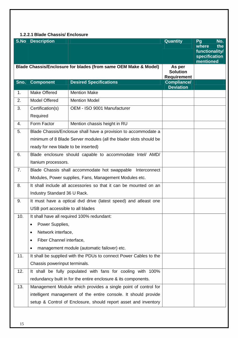
1.2.2.1 Blade Chassis/ Enclosure
S.No Description Quantity
Pg No. where the functionality/ specification mentioned
Blade Chassis/Enclosure for blades (from same OEM Make & Model) As per Solution
Requirement
Sno. Component Desired Specifications Compliance/ Deviation
1. Make Offered Mention Make
2. Model Offered Mention Model
3. Certification(s)
Required
OEM - ISO 9001 Manufacturer
4. Form Factor Mention chassis height in RU
5. Blade Chassis/Enclosue shall have a provision to accommodate a
minimum of 8 Blade Server modules (all the blader slots should be
ready for new blade to be inserted)
6. Blade enclosure should capable to accommodate Intel/ AMD/
Itanium processors.
7. Blade Chassis shall accommodate hot swappable Interconnect
Modules, Power supplies, Fans, Management Modules etc.
8. It shall include all accessories so that it can be mounted on an
Industry Standard 36 U Rack.
9. It must have a optical dvd drive (latest speed) and atleast one
USB port accessible to all blades
10. It shall have all required 100% redundant:
Power Supplies,
Network interface,
Fiber Channel interface,
management module (automatic failover) etc.
11. It shall be supplied with the PDUs to connect Power Cables to the
Chassis powerinput terminals.
12. It shall be fully populated with fans for cooling with 100%
redundancy built in for the entire enclosure & its components.
13. Management Module which provides a single point of control for
intelligent management of the entire console. It should provide
setup & Control of Enclosure, should report asset and inventory

16
Information for all the devices in the Enclosure. It should report
Thermal & Power Information of per Server and it should provide
IP KVM functionalities & Access for all the Server Blades from the
Management Module.
14. Management Modules per Blade/ Chassis providing system
management function and remote management
15. Service and management : Multiple administrators to remotely
access and maintain multiple server blades simultaneously
16. Require two communication modules with support of load
balancing and failover
17. Chassis should be populated with maximum power supplies for
scalability purpose at the time of bidding.
1.2.2.2 Application Web Server (Quantity – 5)
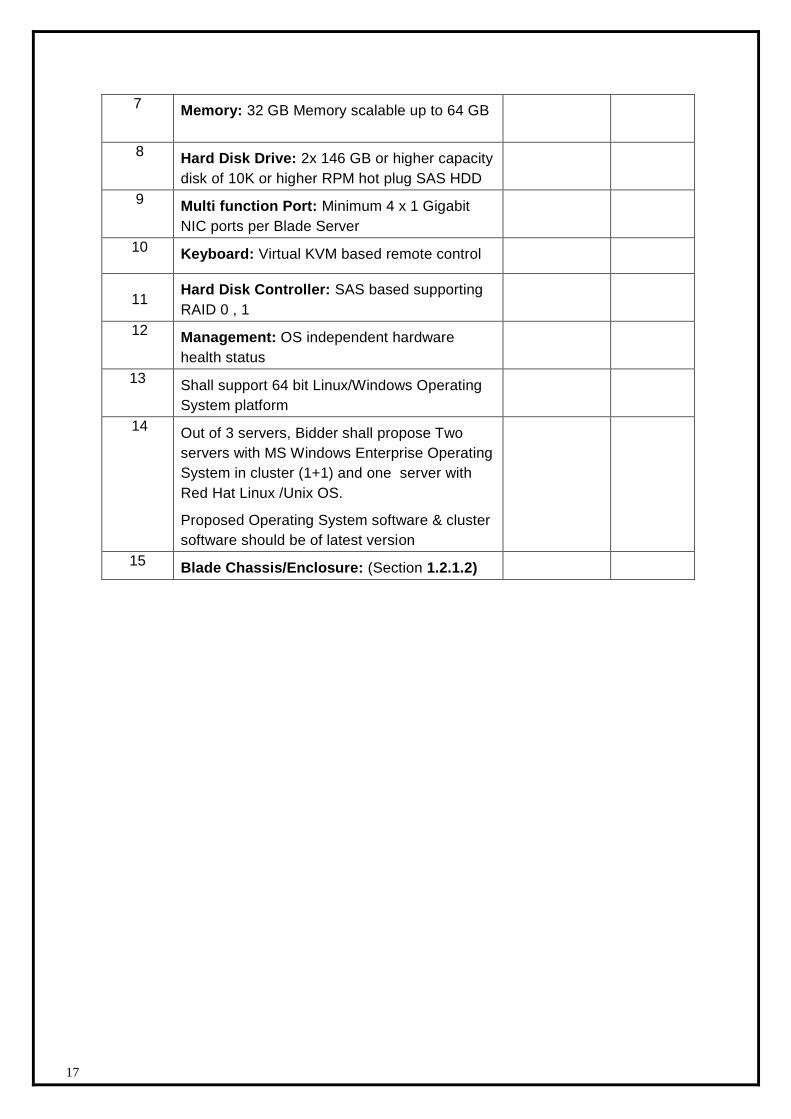
1.2.2.2.1 Hardware specification of x64 Architecture (Quantity – 3)
S.N DESCRIPTION QTY Deviation
Blade Server for Application Web Server 3
Sr. No. Specifications Compliance Deviation (If any)
(Yes/No)
1. Make Offered Mention Make
2. Model Offered Mention Model
3. Certification(s)
Required
OEM - ISO 9001
Manufacturer
Certified on proposed
OS(s)
4. Std. Compliance(s)
Req.
UL, FCC & RoHS
5. Server Form Factor Blade to be inserted
into above blade
enclosure
6
CPU: 1 x Quad Core x64 processor Scalable
upto 2 * Quad core Processor. Processor
speed should be of Min 2.00 GHz
17
7 Memory: 32 GB Memory scalable up to 64 GB
8 Hard Disk Drive: 2x 146 GB or higher capacity
disk of 10K or higher RPM hot plug SAS HDD
9 Multi function Port: Minimum 4 x 1 Gigabit
NIC ports per Blade Server
10 Keyboard: Virtual KVM based remote control
11
Hard Disk Controller: SAS based supporting
RAID 0 , 1
12 Management: OS independent hardware
health status
13 Shall support 64 bit Linux/Windows Operating
System platform
14 Out of 3 servers, Bidder shall propose Two
servers with MS Windows Enterprise Operating
System in cluster (1+1) and one server with
Red Hat Linux /Unix OS.
Proposed Operating System software & cluster
software should be of latest version
15 Blade Chassis/Enclosure: (Section 1.2.1.2)
18
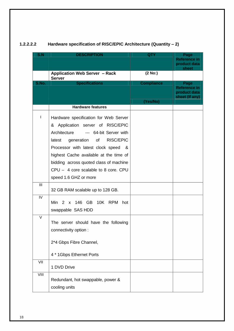
1.2.2.2.2 Hardware specification of RISC/EPIC Architecture (Quantity – 2)
S.N DESCRIPTION QTY Page Reference in product data
sheet
Application Web Server – Rack Server
(2 No:)
S.No. Specifications Compliance Page Reference in product data sheet (If any)
(Yes/No)
Hardware features
I Hardware specification for Web Server
& Application server of RISC/EPIC
Architecture --- 64-bit Server with
latest generation of RISC/EPIC
Processor with latest clock speed &
highest Cache available at the time of
bidding across quoted class of machine
CPU – 4 core scalable to 8 core. CPU
speed 1.6 GHZ or more
III
32 GB RAM scalable up to 128 GB.
IV
Min 2 x 146 GB 10K RPM hot
swappable SAS HDD
V
The server should have the following
connectivity option :
2*4 Gbps Fibre Channel,
4 * 1Gbps Ethernet Ports
VII
1 DVD Drive
VIII
Redundant, hot swappable, power &
cooling units
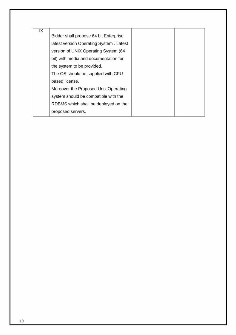
19
IX
Bidder shall propose 64 bit Enterprise
latest version Operating System . Latest
version of UNIX Operating System (64
bit) with media and documentation for
the system to be provided.
The OS should be supplied with CPU
based license.
Moreover the Proposed Unix Operating
system should be compatible with the
RDBMS which shall be deployed on the
proposed servers.
20
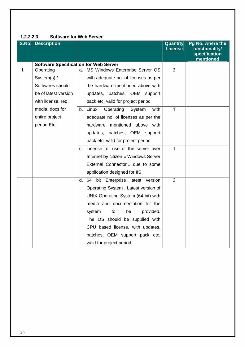
1.2.2.2.3 Software for Web Server
S.No Description Quantity License
Pg No. where the functionality/ specification mentioned
Software Specification for Web Server
1. Operating
System(s) /
Softwares should
be of latest version
with license, req.
media, docs for
entire project
period Etc
a. MS Windows Enterprise Server OS
with adequate no. of licenses as per
the hardware mentioned above with
updates, patches, OEM support
pack etc. valid for project period
2
b. Linux Operating System with
adequate no. of licenses as per the
hardware mentioned above with
updates, patches, OEM support
pack etc. valid for project period
1
c. License for use of the server over
Internet by citizen « Windows Server
External Connector » due to some
application designed for IIS
1
d. 64 bit Enterprise latest version
Operating System . Latest version of
UNIX Operating System (64 bit) with
media and documentation for the
system to be provided.
The OS should be supplied with
CPU based license. with updates,
patches, OEM support pack etc.
valid for project period
2
21
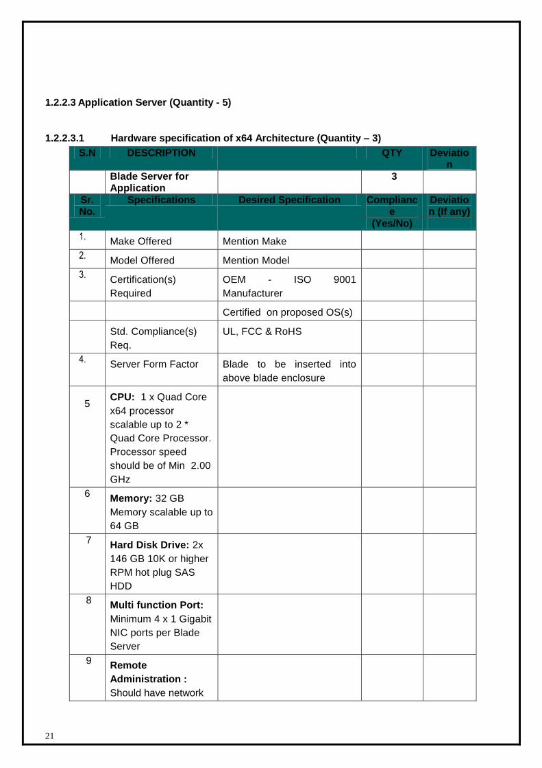
1.2.2.3 Application Server (Quantity - 5)
1.2.2.3.1 Hardware specification of x64 Architecture (Quantity – 3)
S.N DESCRIPTION QTY Deviation
Blade Server for Application
3
Sr. No.
Specifications Desired Specification Compliance
Deviation (If any)
(Yes/No)
1. Make Offered Mention Make
2. Model Offered Mention Model
3. Certification(s)
Required
OEM - ISO 9001
Manufacturer
Certified on proposed OS(s)
Std. Compliance(s)
Req.
UL, FCC & RoHS
4. Server Form Factor Blade to be inserted into
above blade enclosure
5
CPU: 1 x Quad Core
x64 processor
scalable up to 2 *
Quad Core Processor.
Processor speed
should be of Min 2.00
GHz
6 Memory: 32 GB
Memory scalable up to
64 GB
7 Hard Disk Drive: 2x
146 GB 10K or higher
RPM hot plug SAS
HDD
8 Multi function Port:
Minimum 4 x 1 Gigabit
NIC ports per Blade
Server
9 Remote
Administration :
Should have network
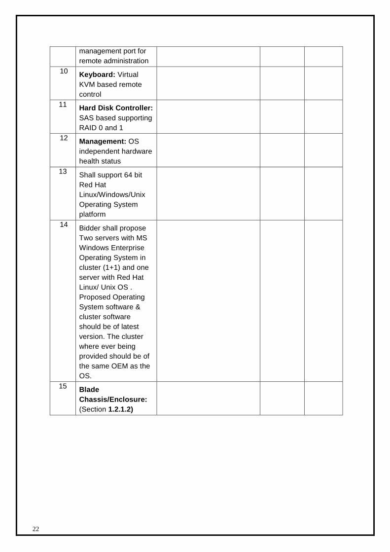
22
management port for
remote administration
10 Keyboard: Virtual
KVM based remote
control
11 Hard Disk Controller:
SAS based supporting
RAID 0 and 1
12 Management: OS
independent hardware
health status
13 Shall support 64 bit
Red Hat
Linux/Windows/Unix
Operating System
platform
14 Bidder shall propose
Two servers with MS
Windows Enterprise
Operating System in
cluster (1+1) and one
server with Red Hat
Linux/ Unix OS .
Proposed Operating
System software &
cluster software
should be of latest
version. The cluster
where ever being
provided should be of
the same OEM as the
OS.
15 Blade
Chassis/Enclosure:
(Section 1.2.1.2)
23
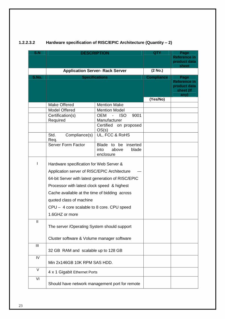
1.2.2.3.2 Hardware specification of RISC/EPIC Architecture (Quantity – 2)
S.N DESCRIPTION QTY Page Reference in product data
sheet
Application Server- Rack Server (2 No.)
S.No. Specifications Compliance Page Reference in product data
sheet (If any)
(Yes/No)
Make Offered Mention Make
Model Offered Mention Model
Certification(s) Required
OEM - ISO 9001 Manufacturer
Certified on proposed OS(s)
Std. Compliance(s) Req.
UL, FCC & RoHS
Server Form Factor Blade to be inserted into above blade enclosure
I Hardware specification for Web Server &
Application server of RISC/EPIC Architecture ---
64-bit Server with latest generation of RISC/EPIC
Processor with latest clock speed & highest
Cache available at the time of bidding across
quoted class of machine
CPU – 4 core scalable to 8 core. CPU speed
1.6GHZ or more
II
The server /Operating System should support
Cluster software & Volume manager software
III
32 GB RAM and scalable up to 128 GB
IV
Min 2x146GB 10K RPM SAS HDD.
V 4 x 1 Gigabit Ethernet Ports
VI
Should have network management port for remote
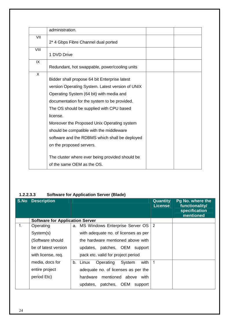
24
administration.
VII
2* 4 Gbps Fibre Channel dual ported
VIII
1 DVD Drive
IX
Redundant, hot swappable, power/cooling units
X
Bidder shall propose 64 bit Enterprise latest
version Operating System. Latest version of UNIX
Operating System (64 bit) with media and
documentation for the system to be provided.
The OS should be supplied with CPU based
license.
Moreover the Proposed Unix Operating system
should be compatible with the middleware
software and the RDBMS which shall be deployed
on the proposed servers.
The cluster where ever being provided should be
of the same OEM as the OS.
1.2.2.3.3 Software for Application Server (Blade)
S.No Description Quantity License
Pg No. where the functionality/ specification mentioned
Software for Application Server
1. Operating
System(s)
(Software should
be of latest version
with license, req.
media, docs for
entire project
period Etc)
a. MS Windows Enterprise Server OS
with adequate no. of licenses as per
the hardware mentioned above with
updates, patches, OEM support
pack etc. valid for project period
2
b. Linux Operating System with
adequate no. of licenses as per the
hardware mentioned above with
updates, patches, OEM support
1
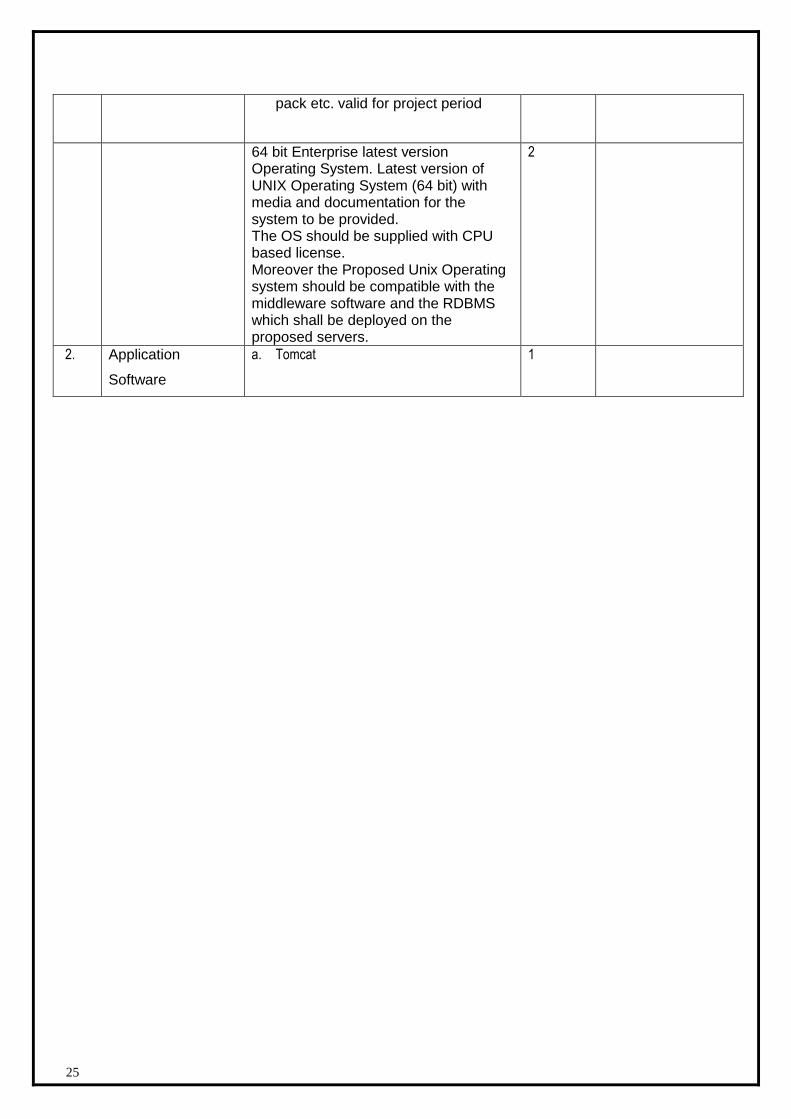
25
pack etc. valid for project period
64 bit Enterprise latest version Operating System. Latest version of UNIX Operating System (64 bit) with media and documentation for the system to be provided. The OS should be supplied with CPU based license. Moreover the Proposed Unix Operating system should be compatible with the middleware software and the RDBMS which shall be deployed on the proposed servers.
2
2. Application
Software
a. Tomcat
1
26
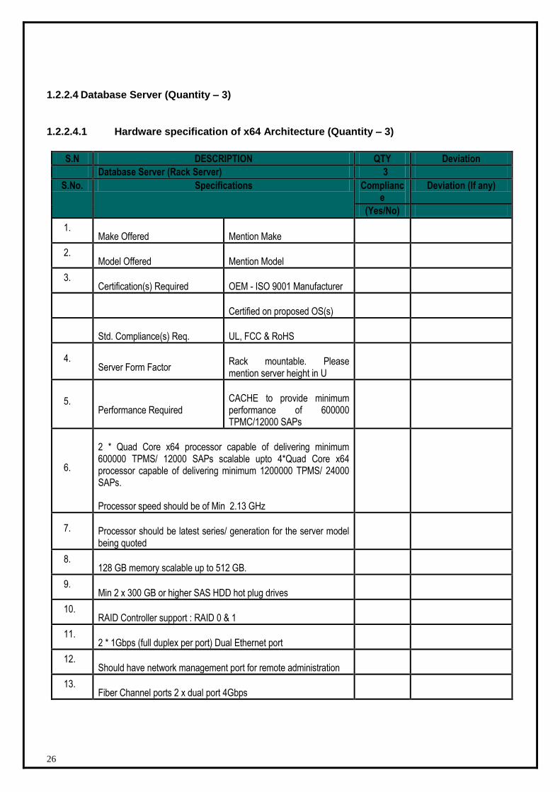
1.2.2.4 Database Server (Quantity – 3)
1.2.2.4.1 Hardware specification of x64 Architecture (Quantity – 3)
S.N DESCRIPTION QTY Deviation
Database Server (Rack Server) 3
S.No. Specifications Compliance
Deviation (If any)
(Yes/No)
1. Make Offered Mention Make
2. Model Offered Mention Model
3. Certification(s) Required OEM - ISO 9001 Manufacturer
Certified on proposed OS(s)
Std. Compliance(s) Req. UL, FCC & RoHS
4. Server Form Factor
Rack mountable. Please mention server height in U
5. Performance Required
CACHE to provide minimum performance of 600000 TPMC/12000 SAPs
6.
2 * Quad Core x64 processor capable of delivering minimum 600000 TPMS/ 12000 SAPs scalable upto 4*Quad Core x64 processor capable of delivering minimum 1200000 TPMS/ 24000 SAPs.
Processor speed should be of Min 2.13 GHz
7. Processor should be latest series/ generation for the server model being quoted
8. 128 GB memory scalable up to 512 GB.
9. Min 2 x 300 GB or higher SAS HDD hot plug drives
10. RAID Controller support : RAID 0 & 1
11. 2 * 1Gbps (full duplex per port) Dual Ethernet port
12. Should have network management port for remote administration
13. Fiber Channel ports 2 x dual port 4Gbps
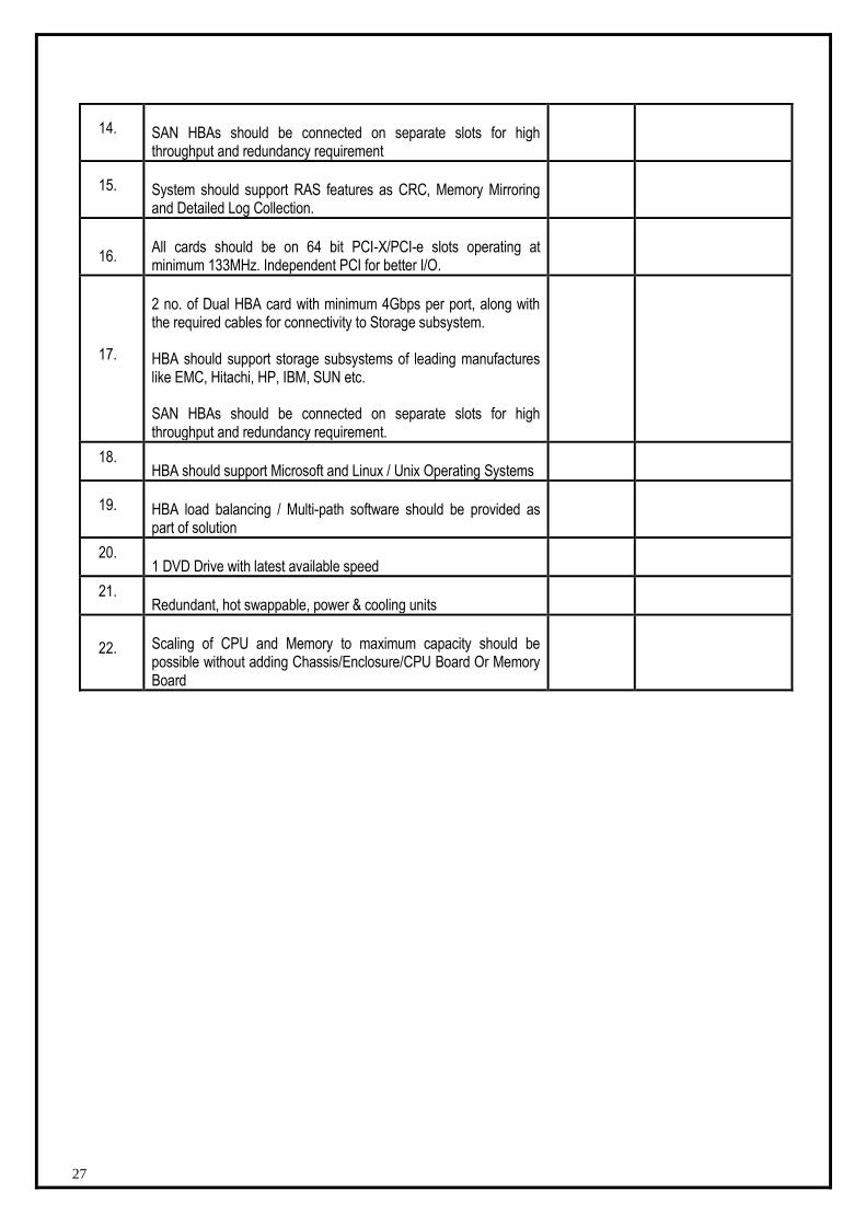
27
14. SAN HBAs should be connected on separate slots for high throughput and redundancy requirement
15. System should support RAS features as CRC, Memory Mirroring and Detailed Log Collection.
16. All cards should be on 64 bit PCI-X/PCI-e slots operating at minimum 133MHz. Independent PCI for better I/O.
17.
2 no. of Dual HBA card with minimum 4Gbps per port, along with the required cables for connectivity to Storage subsystem.
HBA should support storage subsystems of leading manufactures like EMC, Hitachi, HP, IBM, SUN etc.
SAN HBAs should be connected on separate slots for high throughput and redundancy requirement.
18. HBA should support Microsoft and Linux / Unix Operating Systems
19. HBA load balancing / Multi-path software should be provided as part of solution
20. 1 DVD Drive with latest available speed
21. Redundant, hot swappable, power & cooling units
22. Scaling of CPU and Memory to maximum capacity should be possible without adding Chassis/Enclosure/CPU Board Or Memory Board
28
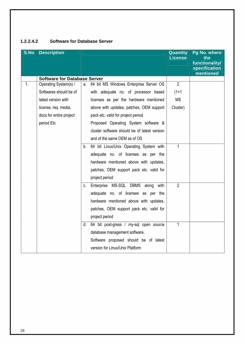
1.2.2.4.2 Software for Database Server
S.No Description Quantity License
Pg No. where the
functionality/ specification mentioned
Software for Database Server
1. Operating System(s) /
Softwares should be of
latest version with
license, req. media,
docs for entire project
period Etc
a. 64 bit MS Windows Enterprise Server OS
with adequate no. of processor based
licenses as per the hardware mentioned
above with updates, patches, OEM support
pack etc. valid for project period.
Proposed Operating System software &
cluster software should be of latest version
and of the same OEM as of OS
2
(1+1
MS
Cluster)
b. 64 bit Linux/Unix Operating System with
adequate no. of licenses as per the
hardware mentioned above with updates,
patches, OEM support pack etc. valid for
project period
1
c. Enterprise MS-SQL DBMS along with
adequate no. of licenses as per the
hardware mentioned above with updates,
patches, OEM support pack etc. valid for
project period
2
d. 64 bit post-gress / my-sql open source
database management software.
Software proposed should be of latest
version for Linux/Unix Platform
1
29
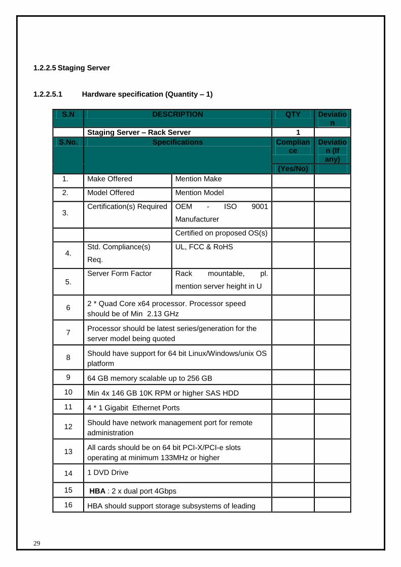
1.2.2.5 Staging Server
1.2.2.5.1 Hardware specification (Quantity – 1)
S.N DESCRIPTION QTY Deviation
Staging Server – Rack Server 1
S.No. Specifications Compliance
Deviation (If any)
(Yes/No)
1. Make Offered Mention Make
2. Model Offered Mention Model
3. Certification(s) Required OEM - ISO 9001
Manufacturer
Certified on proposed OS(s)
4. Std. Compliance(s)
Req.
UL, FCC & RoHS
5. Server Form Factor Rack mountable, pl.
mention server height in U
6 2 * Quad Core x64 processor. Processor speed
should be of Min 2.13 GHz
7 Processor should be latest series/generation for the
server model being quoted
8 Should have support for 64 bit Linux/Windows/unix OS
platform
9 64 GB memory scalable up to 256 GB
10 Min 4x 146 GB 10K RPM or higher SAS HDD
11 4 * 1 Gigabit Ethernet Ports
12 Should have network management port for remote
administration
13 All cards should be on 64 bit PCI-X/PCI-e slots
operating at minimum 133MHz or higher
14 1 DVD Drive
15 HBA : 2 x dual port 4Gbps
16 HBA should support storage subsystems of leading
30
manufactures like EMC, Hitachi, HP, IBM, SUN etc
17 HBA should support Microsoft and Linux/Unix
Operating Systems
18 Redundant, hot swappable, power/cooling units
19 System should have capability to support virtualization
software
20 RAID Controller: RAID controller to support various
levels of RAID
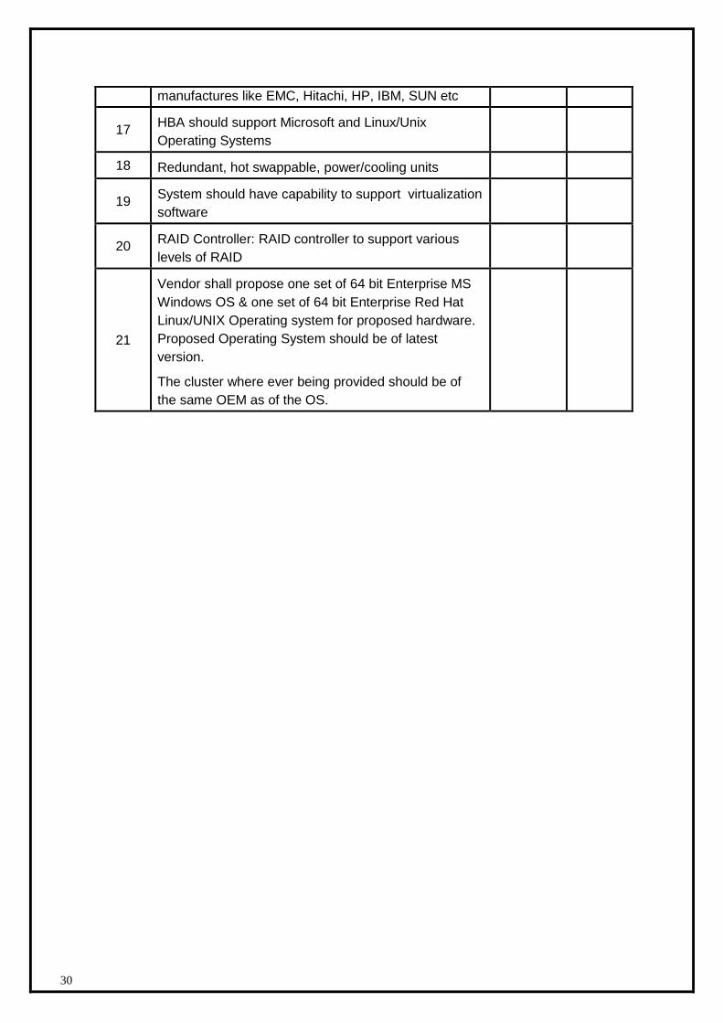
21
Vendor shall propose one set of 64 bit Enterprise MS
Windows OS & one set of 64 bit Enterprise Red Hat
Linux/UNIX Operating system for proposed hardware.
Proposed Operating System should be of latest
version.
The cluster where ever being provided should be of
the same OEM as of the OS.
31
1.2.2.5.2 Software for Staging Server
S.No Description Quantity License
Pg No. where the
functionality/ specification mentioned
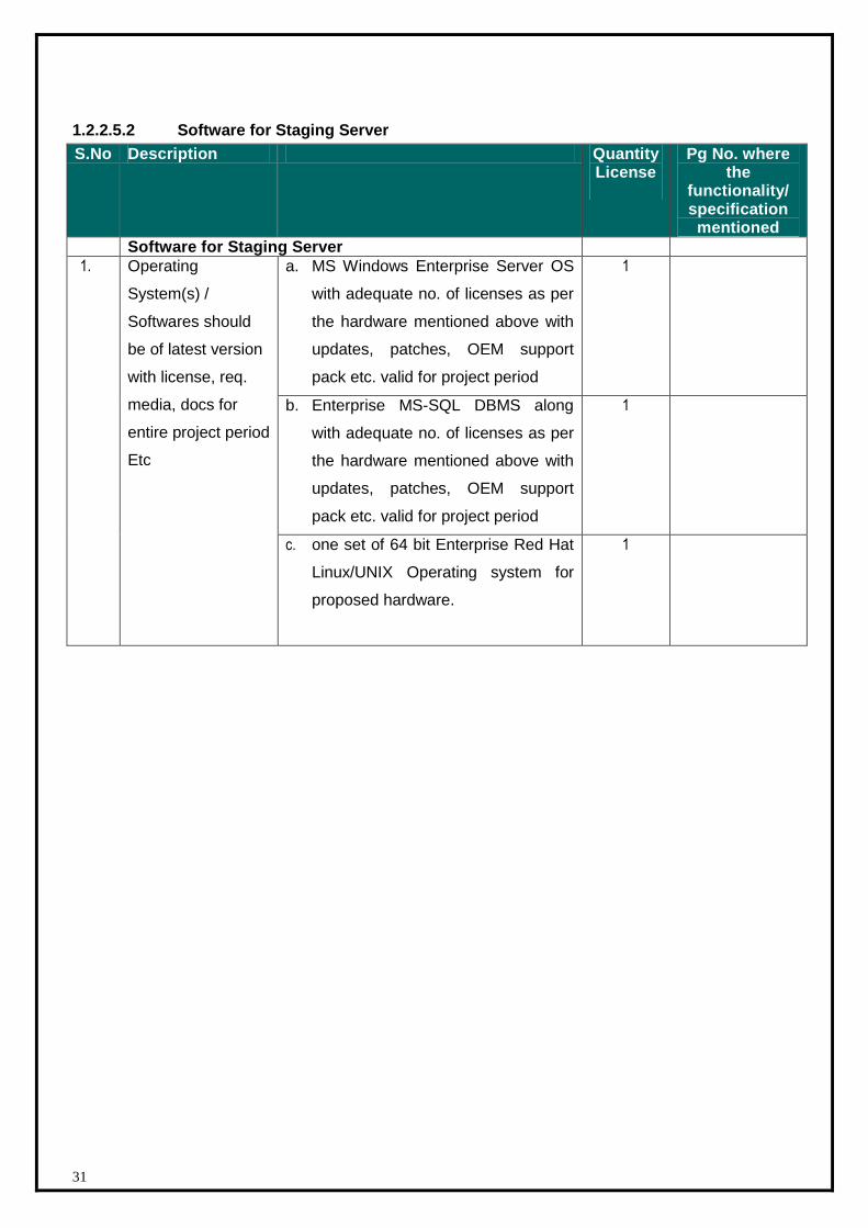
Software for Staging Server
1. Operating
System(s) /
Softwares should
be of latest version
with license, req.
media, docs for
entire project period
Etc
a. MS Windows Enterprise Server OS
with adequate no. of licenses as per
the hardware mentioned above with
updates, patches, OEM support
pack etc. valid for project period
1
b. Enterprise MS-SQL DBMS along
with adequate no. of licenses as per
the hardware mentioned above with
updates, patches, OEM support
pack etc. valid for project period
1
c. one set of 64 bit Enterprise Red Hat
Linux/UNIX Operating system for
proposed hardware.
1
32
1.2.2.6 Storage and Backup Solution
1.2.2.6.1 Storage Hardware specification (Quantity – 1)
S.N DESCRIPTION QTY Page Reference in product data
sheet
Storage (1 No)
S.No. Specifications Compliance Page Reference in product data sheet (If any)
(Yes/No)
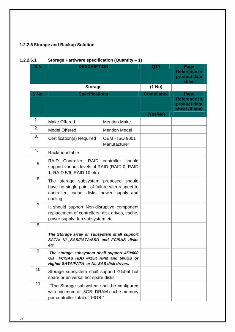
1. Make Offered Mention Make
2. Model Offered Mention Model
3. Certification(s) Required OEM - ISO 9001
Manufacturer
4. Rackmountable
5
RAID Controller: RAID controller should
support various levels of RAID (RAID 0, RAID
1, RAID 5/6, RAID 10 etc)
6 The storage subsystem proposed should
have no single point of failure with respect to
controller, cache, disks, power supply and
cooling
7 It should support Non-disruptive component
replacement of controllers, disk drives, cache,
power supply, fan subsystem etc.
8
The Storage array or subsystem shall support
SATA/ NL_SAS/FATA/SSD and FC/SAS disks
etc
9 The storage subsystem shall support 450/600
GB FC/SAS HDD @15K RPM and 500GB or
Higher SATA/FATA or NL-SAS disk drives.
10 Storage subsystem shall support Global hot
spare or universal hot spare disks
11 “The Storage subsystem shall be configured
with minimum of 8GB DRAM cache memory
per controller total of 16GB.”
33
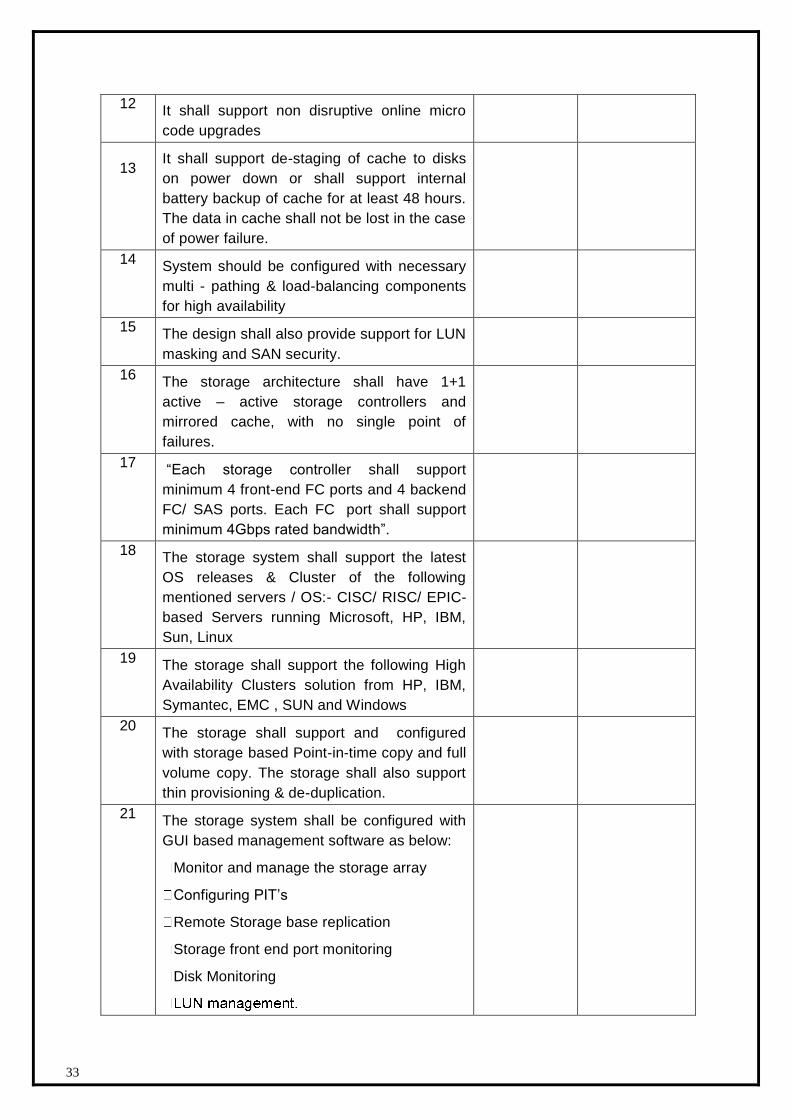
12 It shall support non disruptive online micro
code upgrades
13
It shall support de-staging of cache to disks
on power down or shall support internal
battery backup of cache for at least 48 hours.
The data in cache shall not be lost in the case
of power failure.
14 System should be configured with necessary
multi - pathing & load-balancing components
for high availability
15 The design shall also provide support for LUN
masking and SAN security.
16 The storage architecture shall have 1+1
active – active storage controllers and
mirrored cache, with no single point of
failures.
17 “Each storage controller shall support
minimum 4 front-end FC ports and 4 backend
FC/ SAS ports. Each FC port shall support
minimum 4Gbps rated bandwidth”.
18 The storage system shall support the latest
OS releases & Cluster of the following
mentioned servers / OS:- CISC/ RISC/ EPIC-
based Servers running Microsoft, HP, IBM,
Sun, Linux
19 The storage shall support the following High
Availability Clusters solution from HP, IBM,
Symantec, EMC , SUN and Windows
20 The storage shall support and configured
with storage based Point-in-time copy and full
volume copy. The storage shall also support
thin provisioning & de-duplication.
21 The storage system shall be configured with
GUI based management software as below:
Monitor and manage the storage array
Configuring PIT’s
Remote Storage base replication
Storage front end port monitoring
Disk Monitoring
34
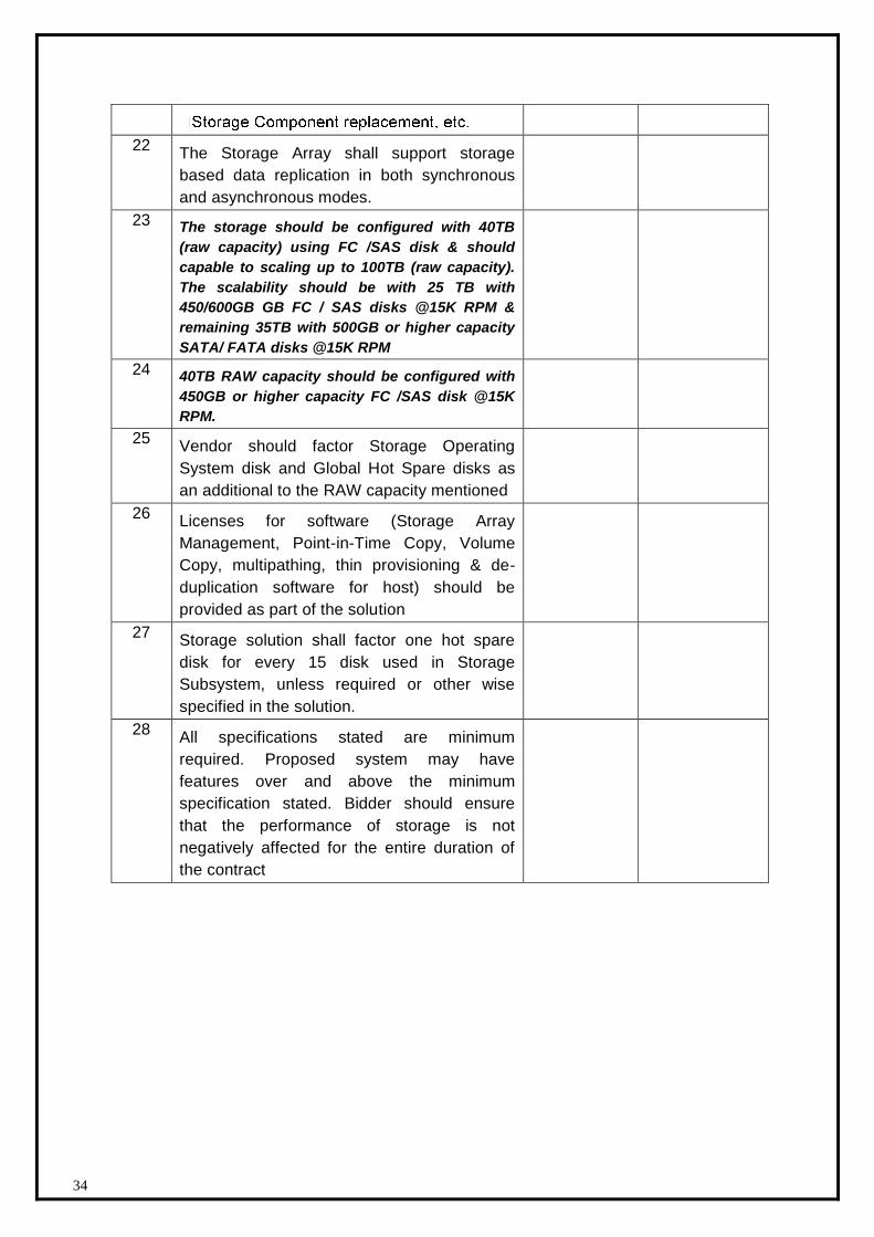
22 The Storage Array shall support storage
based data replication in both synchronous
and asynchronous modes.
23 The storage should be configured with 40TB
(raw capacity) using FC /SAS disk & should
capable to scaling up to 100TB (raw capacity).
The scalability should be with 25 TB with
450/600GB GB FC / SAS disks @15K RPM &
remaining 35TB with 500GB or higher capacity
SATA/ FATA disks @15K RPM
24 40TB RAW capacity should be configured with
450GB or higher capacity FC /SAS disk @15K
RPM.
25 Vendor should factor Storage Operating
System disk and Global Hot Spare disks as
an additional to the RAW capacity mentioned
26 Licenses for software (Storage Array
Management, Point-in-Time Copy, Volume
Copy, multipathing, thin provisioning & de-
duplication software for host) should be
provided as part of the solution
27 Storage solution shall factor one hot spare
disk for every 15 disk used in Storage
Subsystem, unless required or other wise
specified in the solution.
28 All specifications stated are minimum
required. Proposed system may have
features over and above the minimum
specification stated. Bidder should ensure
that the performance of storage is not
negatively affected for the entire duration of
the contract
35
1.2.2.6.2 Backup Solution
Bidders should meet the below given backup window:
Backup solution should be capable of taking data backup @25TB/ 10Hr.
In addition to that Bidder has to take backup of all Server’s of State Data Centre to local Data
backup (Local disk backup) in to the same Tape library. Bidder may consider D2D2T backup
solution to achieve above Backup window.
The backup licenses should be asked for OS, DB and capacity based. The unit for discovery can
be 10 for OS, 5 for DB and 25TB for capacity.
Bidders are free to choose backup solution components to meet above backup window, which
should also include backup server hardware and backup software. Proposed backup solution
should include Tape Library Latest Technology) and Disk Library to backup all the servers in the
datacenter. The vendor shall factor license to ensure backup of the entire server in Data Center.
Bidder should provide the required agents for RDBMS, Application & other component used in
data center for backup. Backup window will remain unchanged for the entire project period.
Backup Media cost would be borne by the bidder.
Bidder has to provide the backup media to achieve the above window and cost for the same
would be borne by the bidder.
DCO shall be responsible for the backup and scalability of the equipments procured by
him i.e. SAN storage and servers. For collocated model where the user departments will
be bringing their own hardware, it will be the user departments’ responsibility to take
backup and DCO will only facilitate the backup.
Tape library should be configured with minimum 100 slots for storing one month Tape backup
inside the Library.
Backup Tape Library configuration should be of latest technology and drive available in
the market and should have enough slots to keep a week’s data tapes inside the
library.
Fire proof cabinet
Required cartridges (pre-labeled barcodes) from the tape library OEM to be provided
Backup window calculation to be done using native data capacity to be backed up. Failure of
hardware extended backup window is an exceptional situation only. Backup Media cost would
be borne by the bidder.
Please mention the specifications of the solution (Tape Library and Disk Library to backup).
36
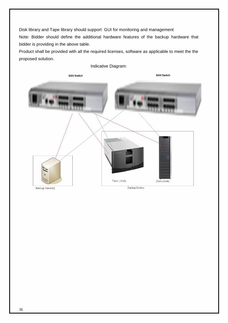
Disk library and Tape library should support GUI for monitoring and management
Note: Bidder should define the additional hardware features of the backup hardware that
bidder is providing in the above table.
Product shall be provided with all the required licenses, software as applicable to meet the the
proposed solution.
Indicative Diagram:
37
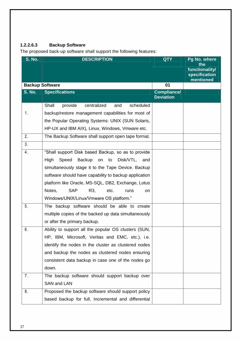
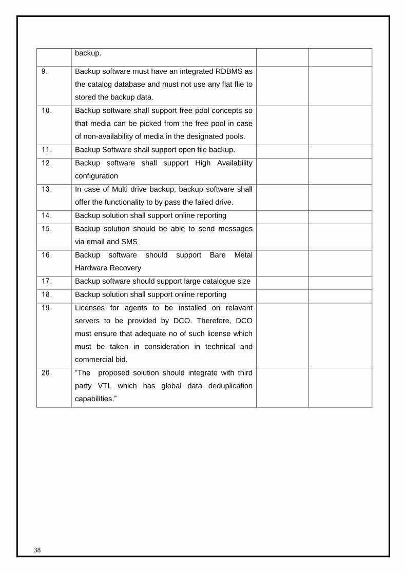
1.2.2.6.3 Backup Software
The proposed back-up software shall support the following features:
S. No. DESCRIPTION QTY
Pg No. where the
functionality/ specification mentioned
Backup Software 01
S. No. Specifications Compliance/ Deviation
1 .
Shall provide centralized and scheduled
backup/restore management capabilities for most of
the Popular Operating Systems: UNIX (SUN Solaris,
HP-UX and IBM AIX), Linux, Windows, Vmware etc.
2 . The Backup Software shall support open tape format.
3 .
4 . “Shall support Disk based Backup, so as to provide
High Speed Backup on to Disk/VTL, and
simultaneously stage it to the Tape Device. Backup
software should have capability to backup application
platform like Oracle, MS-SQL, DB2, Exchange, Lotus
Notes, SAP R3, etc. runs on
Windows/UNIX/Linux/Vmware OS platform.”
5 . The backup software should be able to create
multiple copies of the backed up data simultaneously
or after the primary backup.
6 . Ability to support all the popular OS clusters (SUN,
HP, IBM, Microsoft, Veritas and EMC, etc.), i.e.
identify the nodes in the cluster as clustered nodes
and backup the nodes as clustered nodes ensuring
consistent data backup in case one of the nodes go
down.
7 . The backup software should support backup over
SAN and LAN
8 . Proposed the backup software should support policy
based backup for full, Incremental and differential
38
backup.
9 . Backup software must have an integrated RDBMS as
the catalog database and must not use any flat flie to
stored the backup data.
10 . Backup software shall support free pool concepts so
that media can be picked from the free pool in case
of non-availability of media in the designated pools.
11 . Backup Software shall support open file backup.
12 . Backup software shall support High Availability
configuration
13 . In case of Multi drive backup, backup software shall
offer the functionality to by pass the failed drive.
14 . Backup solution shall support online reporting
15 . Backup solution should be able to send messages
via email and SMS
16 . Backup software should support Bare Metal
Hardware Recovery
17 . Backup software should support large catalogue size
18 . Backup solution shall support online reporting
19 . Licenses for agents to be installed on relavant
servers to be provided by DCO. Therefore, DCO
must ensure that adequate no of such license which
must be taken in consideration in technical and
commercial bid.
20 . “The proposed solution should integrate with third
party VTL which has global data deduplication
capabilities.”
39
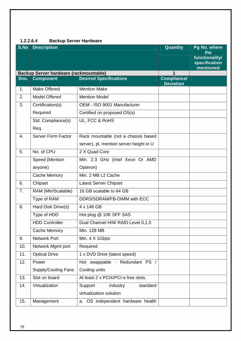
1.2.2.6.4 Backup Server Hardware
S.No Description Quantity
Pg No. where the
functionality/ specification mentioned
Backup Server hardware (rackmountable) 1
Sno. Component Desired Specifications Compliance/ Deviation
1. Make Offered Mention Make
2. Model Offered Mention Model
3. Certification(s)
Required
OEM - ISO 9001 Manufacturer
Certified on proposed OS(s)
Std. Compliance(s)
Req.
UL, FCC & RoHS
4. Server Form Factor Rack mountable (not a chassis based
server), pl. mention server height in U
5. No. of CPU 2 X Quad Core
Speed (Mention
anyone)
Min. 2.3 GHz (Intel Xeon Or AMD
Opteron)
Cache Memory Min. 2 MB L2 Cache
6. Chipset Latest Server Chipset
7. RAM (Min/Scalable) 16 GB scalable to 64 GB
Type of RAM DDR3/SDRAM/FB-DIMM with ECC
8. Hard Disk Drive(s) 4 x 146 GB
Type of HDD Hot plug @ 10K SFF SAS
HDD Controller Dual Channel H/W RAID Level 0,1,5
Cache Memory Min. 128 MB
9. Network Port Min. 4 X 1Gbps
10. Network Mgmt port Required
11. Optical Drive 1 x DVD Drive (latest speed)
12. Power
Supply/Cooling Fans
Hot swappable - Redundant PS /
Cooling units
13. Slot on board At least 2 x PCIX/PCI-e free slots.
14. Virtualization Support industry standard
virtualization solution
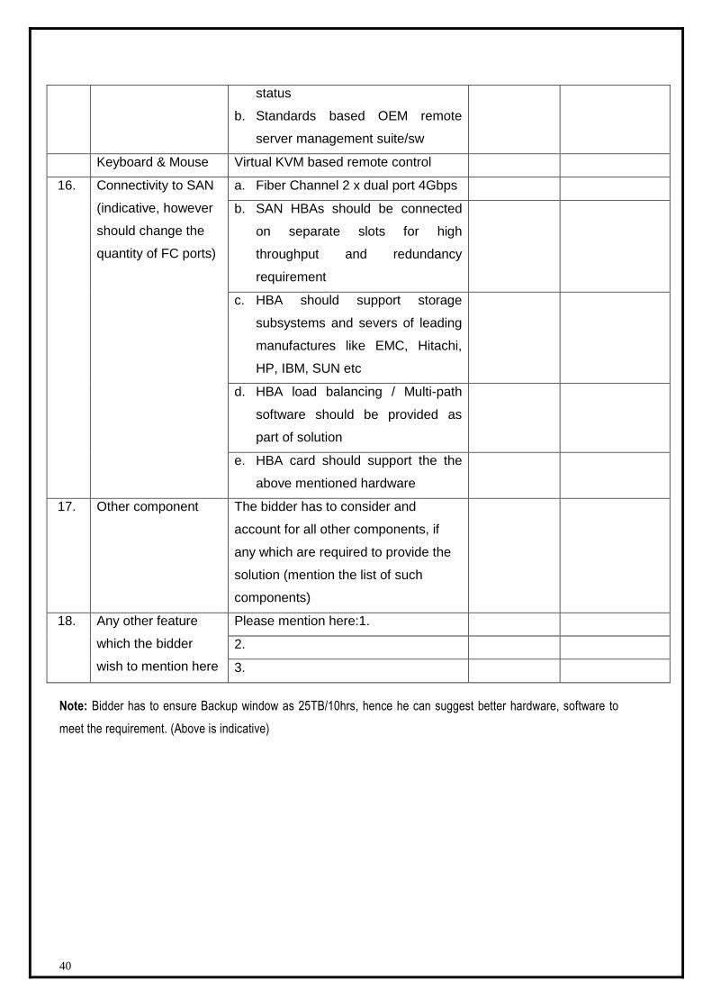
15. Management a. OS independent hardware health
40
status
b. Standards based OEM remote
server management suite/sw
Keyboard & Mouse Virtual KVM based remote control
16. Connectivity to SAN
(indicative, however
should change the
quantity of FC ports)
a. Fiber Channel 2 x dual port 4Gbps
b. SAN HBAs should be connected
on separate slots for high
throughput and redundancy
requirement
c. HBA should support storage
subsystems and severs of leading
manufactures like EMC, Hitachi,
HP, IBM, SUN etc
d. HBA load balancing / Multi-path
software should be provided as
part of solution
e. HBA card should support the the
above mentioned hardware
17. Other component The bidder has to consider and
account for all other components, if
any which are required to provide the
solution (mention the list of such
components)
18. Any other feature
which the bidder
wish to mention here
Please mention here:1.
2.
3.
Note: Bidder has to ensure Backup window as 25TB/10hrs, hence he can suggest better hardware, software to
meet the requirement. (Above is indicative)
41
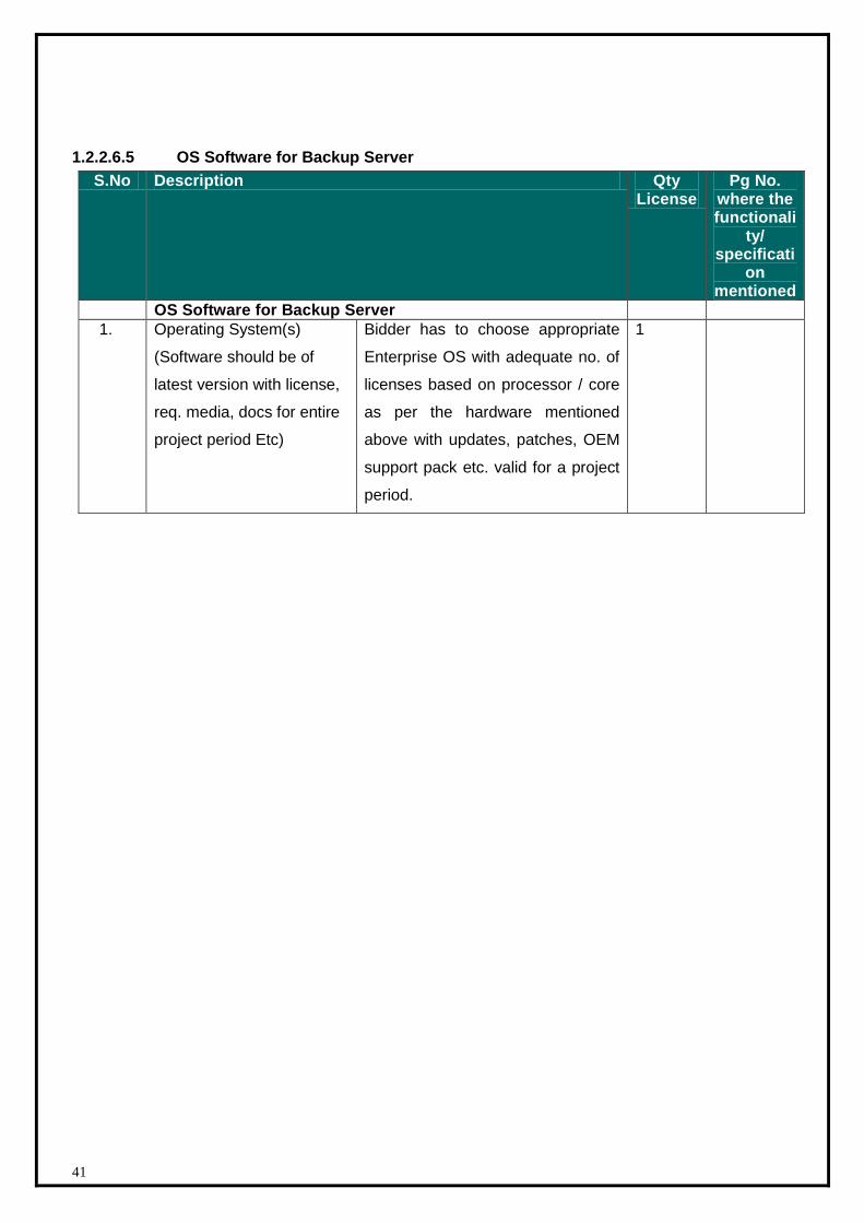
1.2.2.6.5 OS Software for Backup Server
S.No Description Qty License
Pg No. where the functionali
ty/ specificati
on mentioned
OS Software for Backup Server
1. Operating System(s)
(Software should be of
latest version with license,
req. media, docs for entire
project period Etc)
Bidder has to choose appropriate
Enterprise OS with adequate no. of
licenses based on processor / core
as per the hardware mentioned
above with updates, patches, OEM
support pack etc. valid for a project
period.
1
42
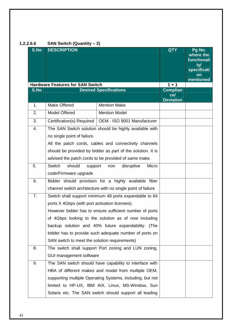
1.2.2.6.6 SAN Switch (Quantity – 2)
S.No DESCRIPTION QTY Pg No. where the functionali
ty/ specificati
on mentioned
Hardware Features for SAN Switch 1 + 1
S.No Desired Specifications Compliance/
Deviation
1. Make Offered Mention Make
2. Model Offered Mention Model
3. Certification(s) Required OEM - ISO 9001 Manufacturer
4. The SAN Switch solution should be highly available with
no single point of failure.
All the patch cords, cables and connectivity channels
should be provided by bidder as part of the solution. It is
advised the patch cords to be provided of same make.
5. Switch should support non disruptive Micro
code/Firmware upgrade
6. Bidder should provision for a highly available fiber
channel switch architecture with no single point of failure
7. Switch shall support minimum 48 ports expandable to 64
ports X 4Gbps (with port activation licenses).
However bidder has to ensure sufficient number of ports
of 4Gbps looking to the solution as of now including
backup solution and 40% future expandability. (The
bidder has to provide such adequate number of ports on
SAN switch to meet the solution requirements)
8. The switch shall support Port zoning and LUN zoning,
GUI management software
9. The SAN switch should have capability to interface with
HBA of different makes and model from multiple OEM,
supporting multiple Operating Systems, including, but not
limited to HP-UX, IBM AIX, Linux, MS-Window, Sun
Solaris etc. The SAN switch should support all leading
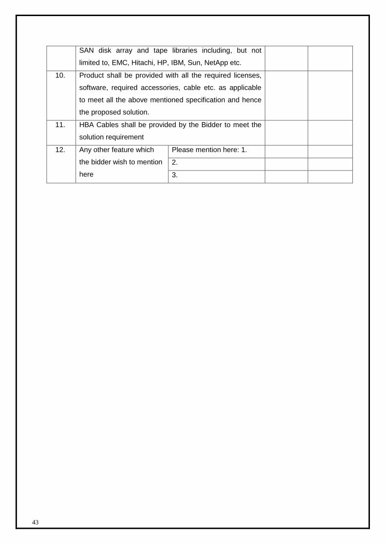
43
SAN disk array and tape libraries including, but not
limited to, EMC, Hitachi, HP, IBM, Sun, NetApp etc.
10. Product shall be provided with all the required licenses,
software, required accessories, cable etc. as applicable
to meet all the above mentioned specification and hence
the proposed solution.
11. HBA Cables shall be provided by the Bidder to meet the
solution requirement
12. Any other feature which
the bidder wish to mention
here
Please mention here: 1.
2.
3.
44
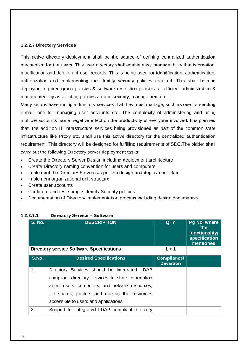
1.2.2.7 Directory Services
This active directory deployment shall be the source of defining centralized authentication
mechanism for the users. This user directory shall enable easy manageability that is creation,
modification and deletion of user records. This is being used for identification, authentication,
authorization and implementing the identity security policies required. This shall help in
deploying required group policies & software restriction policies for efficient administration &
management by associating policies around security, management etc.
Many setups have multiple directory services that they must manage, such as one for sending
e-mail, one for managing user accounts etc. The complexity of administering and using
multiple accounts has a negative effect on the productivity of everyone involved. It is planned
that, the addition IT infrastructure services being provisioned as part of the common state
infrastructure like Proxy etc. shall use this active directory for the centralized authentication
requirement. This directory will be designed for fulfilling requirements of SDC.The bidder shall
carry out the following Directory server deployment tasks:
Create the Directory Server Design including deployment architecture
Create Directory naming convention for users and computers
Implement the Directory Servers as per the design and deployment plan
Implement organizational unit structure
Create user accounts
Configure and test sample identity Security policies
Documentation of Directory implementation process including design documentss
1.2.2.7.1 Directory Service – Software
S. No. DESCRIPTION QTY Pg No. where the
functionality/ specification mentioned
Directory service Software Specifications 1 + 1
S.No. Desired Specifications
Compliance/ Deviation
1. Directory Services should be integrated LDAP
compliant directory services to store information
about users, computers, and network resources,
file shares, printers and making the resources
accessible to users and applications
2. Support for integrated LDAP compliant directory

45
services to record information for users, and
system resources
3. Should support integrated authentication
mechanism across operating system, messaging
services
4. Should support directory services for ease of
management and administration/replication
5. Should support security features, such as
Kerberos public key infrastructure (PKI), etc
6. Should provide support for X.500 naming
standards
7. Should support Kerberos for logon and
authentication
8. Should support that user account creation/deletion
rights within a group or groups can be delegated
to any nominated user
9. Product shall be provided with all the required
licenses, software as applicable to meet all the
above mentioned specification and hence the
proposed solution.
10. Client licenses if required would be 50 in number
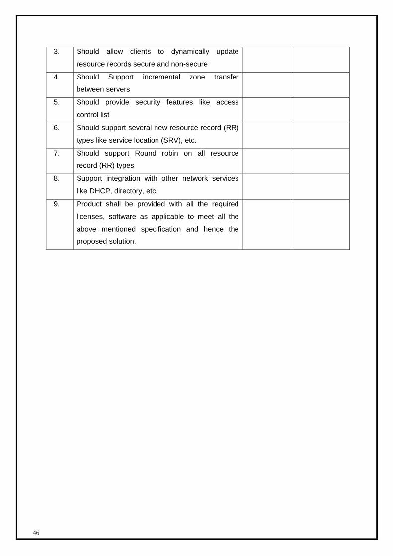
1.2.2.7.2 DNS, DHCP - Software specifications :
S.No. DESCRIPTION QTY Pg No. where the
functionality/ specification mentioned
DNS, DHCP Software 1 + 1
S.No. Specifications Compliance/ Deviation
Software features
1. Support integration with other network services
like DHCP, directory, etc.
2. Should support DNS forwarders e.g. forwarding
based on a DNS Domain name in the query.
46
3. Should allow clients to dynamically update
resource records secure and non-secure
4. Should Support incremental zone transfer
between servers
5. Should provide security features like access
control list
6. Should support several new resource record (RR)
types like service location (SRV), etc.
7. Should support Round robin on all resource
record (RR) types
8. Support integration with other network services
like DHCP, directory, etc.
9. Product shall be provided with all the required
licenses, software as applicable to meet all the
above mentioned specification and hence the
proposed solution.
47
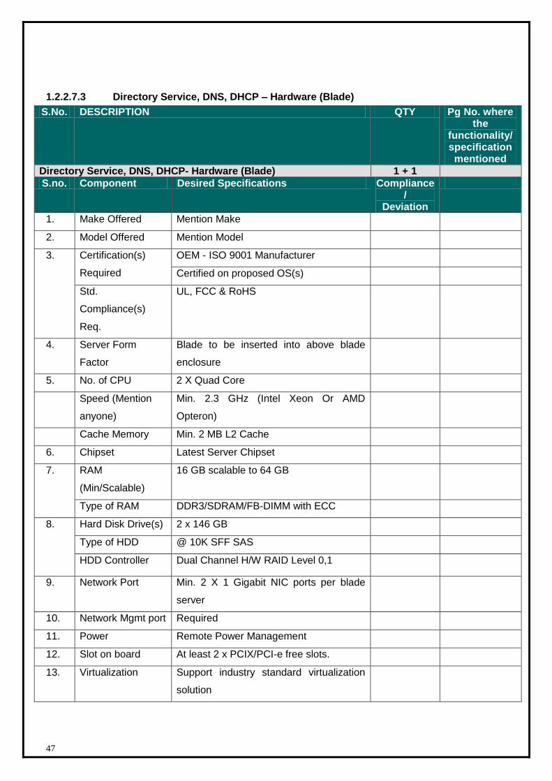
1.2.2.7.3 Directory Service, DNS, DHCP – Hardware (Blade)
S.No. DESCRIPTION QTY Pg No. where the
functionality/ specification mentioned
Directory Service, DNS, DHCP- Hardware (Blade) 1 + 1
S.no. Component Desired Specifications Compliance/
Deviation
1. Make Offered Mention Make
2. Model Offered Mention Model
3. Certification(s)
Required
OEM - ISO 9001 Manufacturer
Certified on proposed OS(s)
Std.
Compliance(s)
Req.
UL, FCC & RoHS
4. Server Form
Factor
Blade to be inserted into above blade
enclosure
5. No. of CPU 2 X Quad Core
Speed (Mention
anyone)
Min. 2.3 GHz (Intel Xeon Or AMD
Opteron)
Cache Memory Min. 2 MB L2 Cache
6. Chipset Latest Server Chipset
7. RAM
(Min/Scalable)
16 GB scalable to 64 GB
Type of RAM DDR3/SDRAM/FB-DIMM with ECC
8. Hard Disk Drive(s) 2 x 146 GB
Type of HDD @ 10K SFF SAS
HDD Controller Dual Channel H/W RAID Level 0,1
9. Network Port Min. 2 X 1 Gigabit NIC ports per blade
server
10. Network Mgmt port Required
11. Power Remote Power Management
12. Slot on board At least 2 x PCIX/PCI-e free slots.
13. Virtualization Support industry standard virtualization
solution
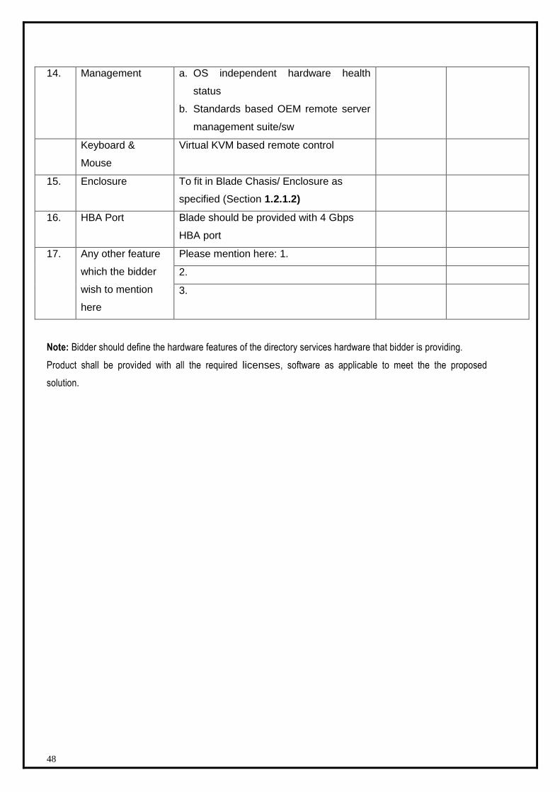
48
14. Management a. OS independent hardware health
status
b. Standards based OEM remote server
management suite/sw
Keyboard &
Mouse
Virtual KVM based remote control
15. Enclosure To fit in Blade Chasis/ Enclosure as
specified (Section 1.2.1.2)
16. HBA Port Blade should be provided with 4 Gbps
HBA port
17. Any other feature
which the bidder
wish to mention
here
Please mention here: 1.
2.
3.
Note: Bidder should define the hardware features of the directory services hardware that bidder is providing.
Product shall be provided with all the required licenses, software as applicable to meet the the proposed
solution.
49
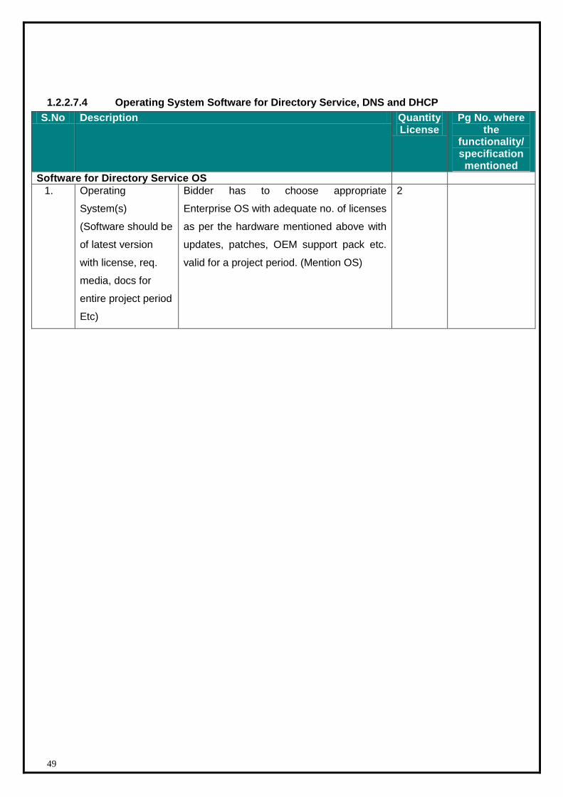
1.2.2.7.4 Operating System Software for Directory Service, DNS and DHCP
S.No Description Quantity License
Pg No. where the
functionality/ specification mentioned
Software for Directory Service OS
1. Operating
System(s)
(Software should be
of latest version
with license, req.
media, docs for
entire project period
Etc)
Bidder has to choose appropriate
Enterprise OS with adequate no. of licenses
as per the hardware mentioned above with
updates, patches, OEM support pack etc.
valid for a project period. (Mention OS)
2
50
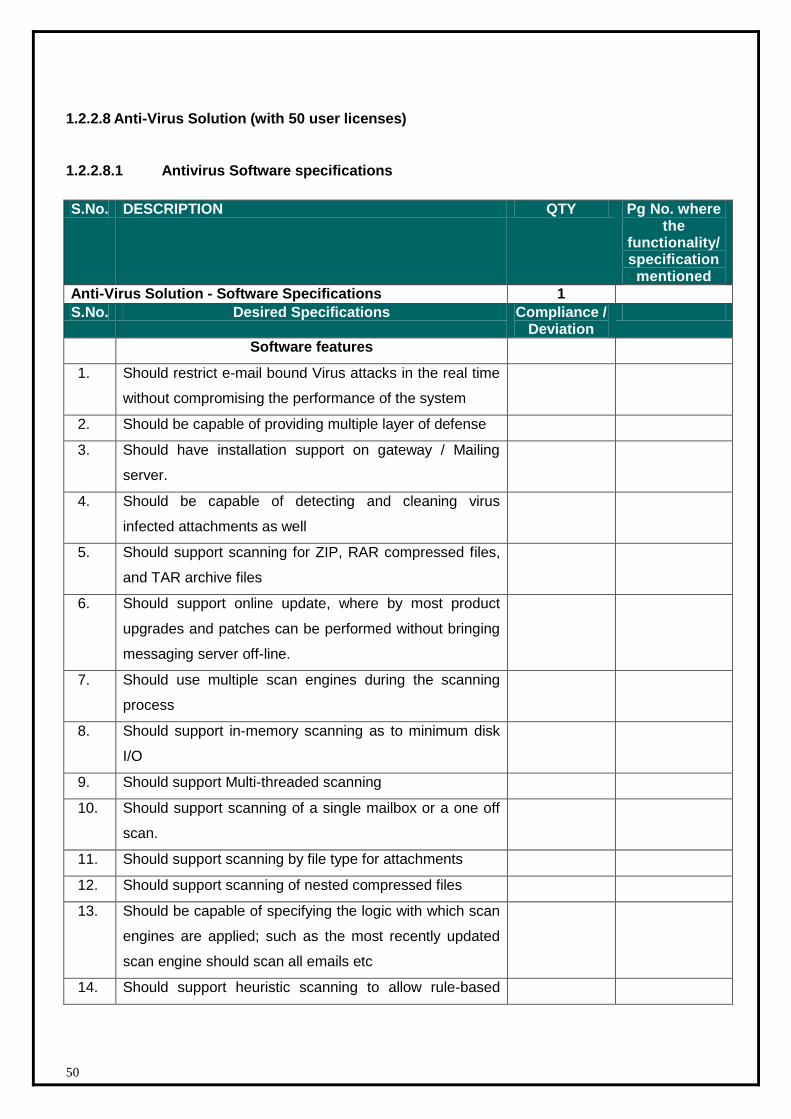
1.2.2.8 Anti-Virus Solution (with 50 user licenses)
1.2.2.8.1 Antivirus Software specifications
S.No. DESCRIPTION QTY Pg No. where the
functionality/ specification mentioned
Anti-Virus Solution - Software Specifications 1
S.No. Desired Specifications Compliance / Deviation
Software features
1. Should restrict e-mail bound Virus attacks in the real time
without compromising the performance of the system
2. Should be capable of providing multiple layer of defense
3. Should have installation support on gateway / Mailing
server.
4. Should be capable of detecting and cleaning virus
infected attachments as well
5. Should support scanning for ZIP, RAR compressed files,
and TAR archive files
6. Should support online update, where by most product
upgrades and patches can be performed without bringing
messaging server off-line.
7. Should use multiple scan engines during the scanning
process
8. Should support in-memory scanning as to minimum disk
I/O
9. Should support Multi-threaded scanning
10. Should support scanning of a single mailbox or a one off
scan.
11. Should support scanning by file type for attachments
12. Should support scanning of nested compressed files
13. Should be capable of specifying the logic with which scan
engines are applied; such as the most recently updated
scan engine should scan all emails etc
14. Should support heuristic scanning to allow rule-based

51
detection of unknown viruses
15. Updates to the scan engines should be automated and
should not require manual intervention
16. Updates should not cause queuing or rejection of email
17. Updates should be capable of being rolled back in case
required
18. Should support content filtering based on sender or
domain filtering
19. Should provide content filtering for message body and
subject line, blocking messages that contain keywords for
inappropriate content
20. File filtering should be supported by the proposed
solution; file filtering should be based on true file type.
21. Common solution for anti-spy ware and anti-virus
infections; and anti-virus and anti-spy ware solution
should have a common web based management console.
22. Should support various types of reporting formats such as
CSV, HTML and text files
23. Should be capable of being managed by a central
management station
24. Should support client lockdown feature for preventing
desktop users from changing real-time settings
25. Should support insertion of disclaimers to message
bodies
26. Product shall be provided with all the required licenses,
software as applicable to meet all the above mentioned
specification and hence the proposed solution.
27. The bidder has to account for the following client antivirus
software :
1. for all servers being installed in the SDC
2. for all other computing devices such as desktops,
laptops etc.
28. The bidder would ensure client antivirus subscriotion valid
for the period of project, therefore, no. of client antivirus
software/solution, there subscription should work for the
project period with out any expiration of services.

52
29. The antivirus solution should be avilable on cross platform
i.e. Windows, RHEL etc. available in the SDC
30. Anti virus software should be provided with 50 user
licenses.
53
1.2.2.8.2 Anti-Virus Solution – Hardware
S.No Description Qty Pg No. where the functionality/
specification mentioned
Anti-Virus Solution – Hardware – Blade Server 1
S.No. Component Desired Specifications Compliance/ Deviation
1. Make Offered Mention Make
2. Model Offered Mention Model
3. Certification(s)
Required
OEM - ISO 9001 Manufacturer
Certified on proposed OS(s)
Std. Compliance(s) UL, FCC & RoHS
4. Server Form Factor Rack mountable (not a chassis
based server), pl. mention
server height in U
5. No. of CPU 2 X Quad Core
Speed (Mention
anyone)
Min. 2.3 GHz (Intel Xeon Or
AMD Opteron)
Cache Memory Min. 2 MB L2 Cache
6. Chipset Latest Server Chipset
7. RAM (Min/Scalable) 16 GB scalable to 64 GB
Type of RAM DDR3/SDRAM/FB-DIMM with
ECC
8. Hard Disk Drive(s) 4 x 146 GB scalable up to min.
6 such HDD
Type of HDD Hot plug @ 10K SFF SAS
HDD Controller Dual Channel H/W RAID Level
0,1
9. Network Port Min. 2 X 1Gbps
10. Network Mgmt port Required
11. Optical Drive 1 x DVD Drive(latest speed)
12. Power Supply/Cooling
Fans
Hot swappable - Redundant PS
/ Cooling units
13. Slot on board At least 2 x PCIX/PCIE free
slots
14. Virtualization Support industry standard
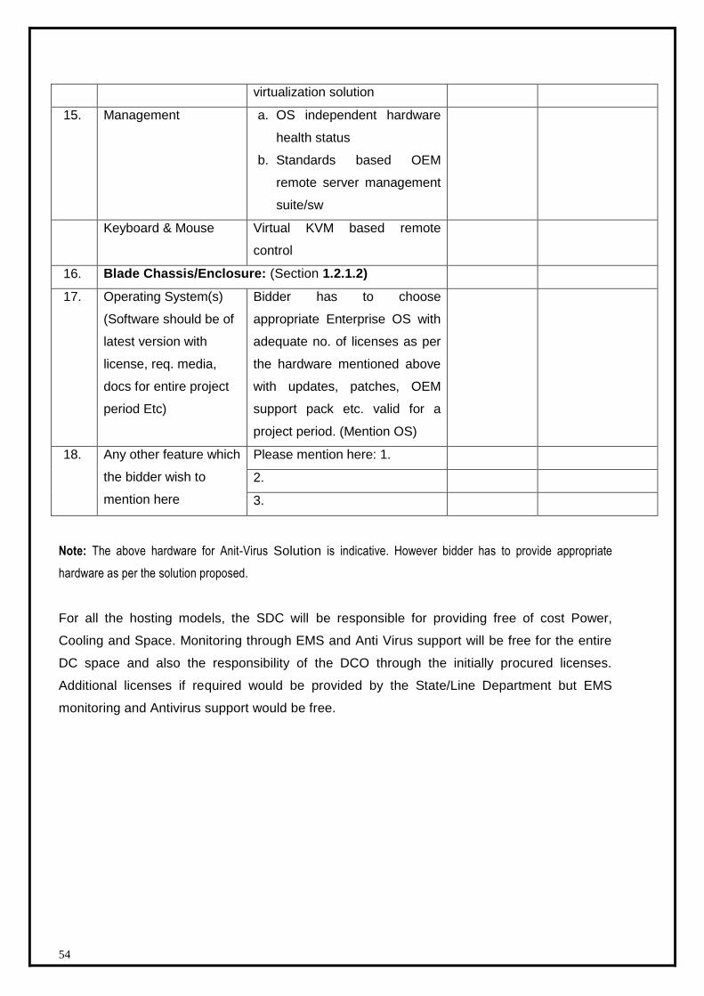
54
virtualization solution
15. Management a. OS independent hardware
health status
b. Standards based OEM
remote server management
suite/sw
Keyboard & Mouse Virtual KVM based remote
control
16. Blade Chassis/Enclosure: (Section 1.2.1.2)
17. Operating System(s)
(Software should be of
latest version with
license, req. media,
docs for entire project
period Etc)
Bidder has to choose
appropriate Enterprise OS with
adequate no. of licenses as per
the hardware mentioned above
with updates, patches, OEM
support pack etc. valid for a
project period. (Mention OS)
18. Any other feature which
the bidder wish to
mention here
Please mention here: 1.
2.
3.
Note: The above hardware for Anit-Virus Solution is indicative. However bidder has to provide appropriate
hardware as per the solution proposed.
For all the hosting models, the SDC will be responsible for providing free of cost Power,
Cooling and Space. Monitoring through EMS and Anti Virus support will be free for the entire
DC space and also the responsibility of the DCO through the initially procured licenses.
Additional licenses if required would be provided by the State/Line Department but EMS
monitoring and Antivirus support would be free.
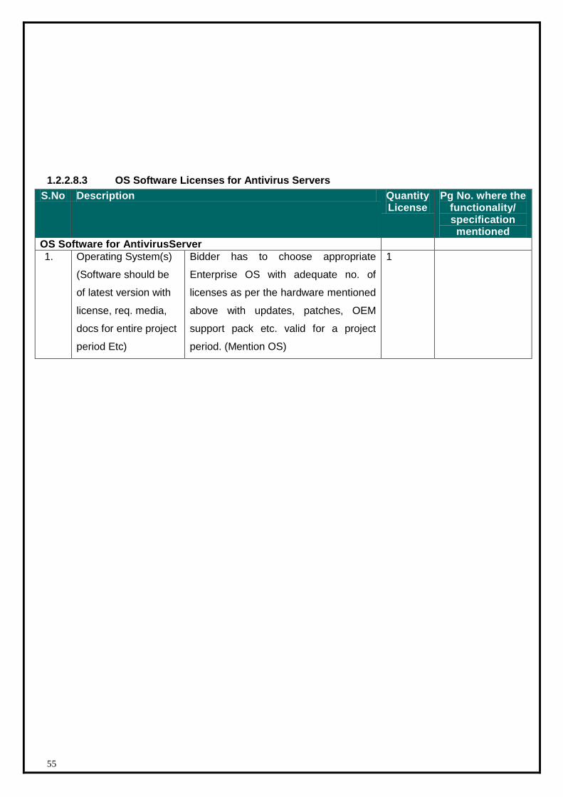
55
1.2.2.8.3 OS Software Licenses for Antivirus Servers
S.No Description Quantity License
Pg No. where the functionality/ specification mentioned
OS Software for AntivirusServer
1. Operating System(s)
(Software should be
of latest version with
license, req. media,
docs for entire project
period Etc)
Bidder has to choose appropriate
Enterprise OS with adequate no. of
licenses as per the hardware mentioned
above with updates, patches, OEM
support pack etc. valid for a project
period. (Mention OS)
1

56
1.2.2.9 Management Solution
1.2.2.9.1 Management Solution - Software Specification
S.No DESCRIPTION QTY Pg No. where the
functionality/ specification mentioned
Management Server – Software 1
S.No. Desired Specifications Compliance/ Deviation
Features
1. Bidder should propose the software for the security
and network management solution for the state
Datacenter which should be integrated with the EMS
solution.
2. Product shall be provided with all the required
licenses, software as applicable to meet all the above
mentioned specification and hence the proposed
solution.
1.2.2.9.2 Management Servers – Hardware
S.No. DESCRIPTION QTY Pg No. where the
functionality/ specification mentioned
Management Server 1
S.No. Component Desired Specifications Compliance/ Deviation
1. Make Offered Mention Make
2. Model Offered Mention Model
3. Certification(s) Req. OEM - ISO 9001 Manufacturer
Certified on proposed OS(s)
Std. Compliance(s) UL, FCC & RoHS
4. Server Form Factor Rack mountable(not a chassis based
server),, pl. mention server height in U
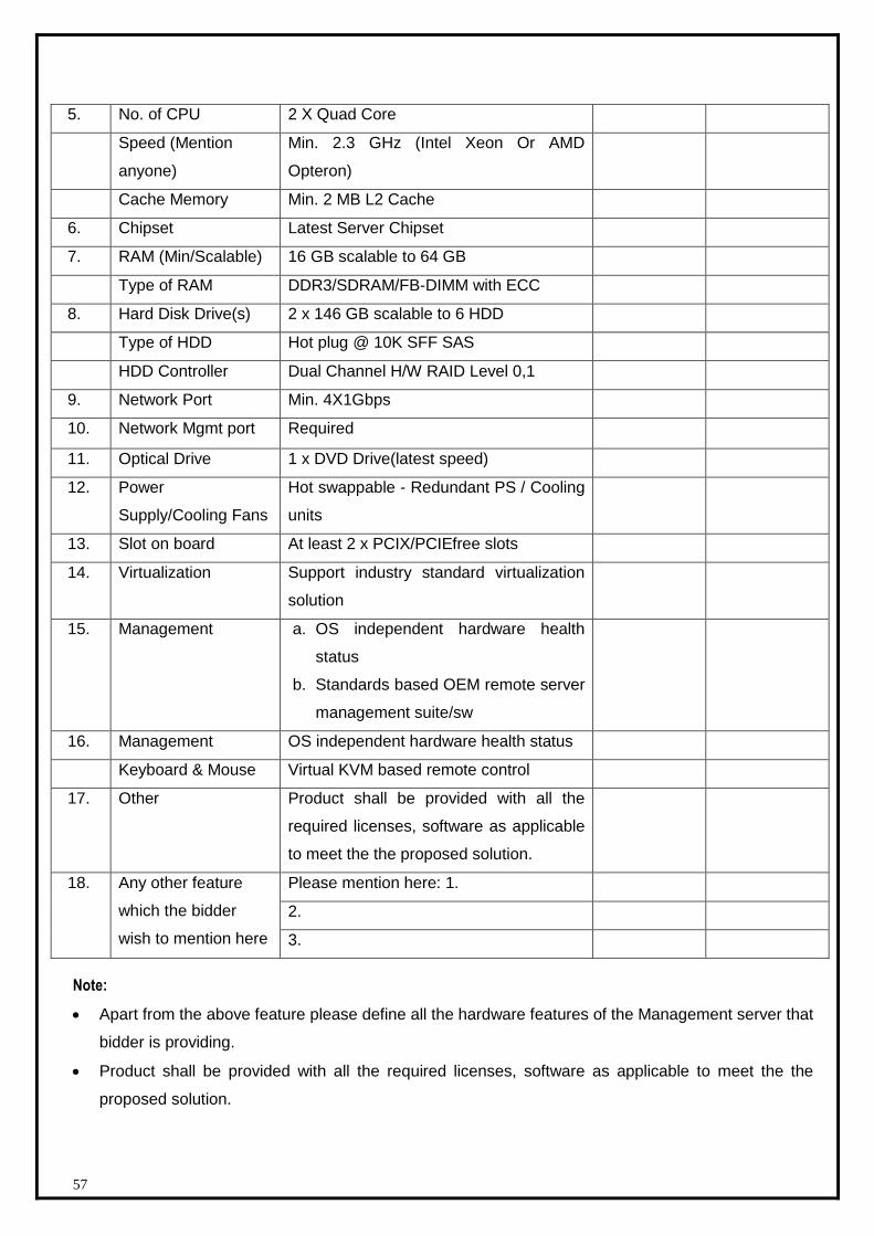
57
5. No. of CPU 2 X Quad Core
Speed (Mention
anyone)
Min. 2.3 GHz (Intel Xeon Or AMD
Opteron)
Cache Memory Min. 2 MB L2 Cache
6. Chipset Latest Server Chipset
7. RAM (Min/Scalable) 16 GB scalable to 64 GB
Type of RAM DDR3/SDRAM/FB-DIMM with ECC
8. Hard Disk Drive(s) 2 x 146 GB scalable to 6 HDD
Type of HDD Hot plug @ 10K SFF SAS
HDD Controller Dual Channel H/W RAID Level 0,1
9. Network Port Min. 4X1Gbps
10. Network Mgmt port Required
11. Optical Drive 1 x DVD Drive(latest speed)
12. Power
Supply/Cooling Fans
Hot swappable - Redundant PS / Cooling
units
13. Slot on board At least 2 x PCIX/PCIEfree slots
14. Virtualization Support industry standard virtualization
solution
15. Management a. OS independent hardware health
status
b. Standards based OEM remote server
management suite/sw
16. Management OS independent hardware health status
Keyboard & Mouse Virtual KVM based remote control
17. Other Product shall be provided with all the
required licenses, software as applicable
to meet the the proposed solution.
18. Any other feature
which the bidder
wish to mention here
Please mention here: 1.
2.
3.
Note:
Apart from the above feature please define all the hardware features of the Management server that
bidder is providing.
Product shall be provided with all the required licenses, software as applicable to meet the the
proposed solution.
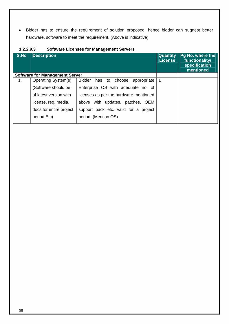
58
Bidder has to ensure the requirement of solution proposed, hence bidder can suggest better
hardware, software to meet the requirement. (Above is indicative)
1.2.2.9.3 Software Licenses for Management Servers
S.No Description Quantity License
Pg No. where the functionality/ specification mentioned
Software for Management Server
1. Operating System(s)
(Software should be
of latest version with
license, req. media,
docs for entire project
period Etc)
Bidder has to choose appropriate
Enterprise OS with adequate no. of
licenses as per the hardware mentioned
above with updates, patches, OEM
support pack etc. valid for a project
period. (Mention OS)
1
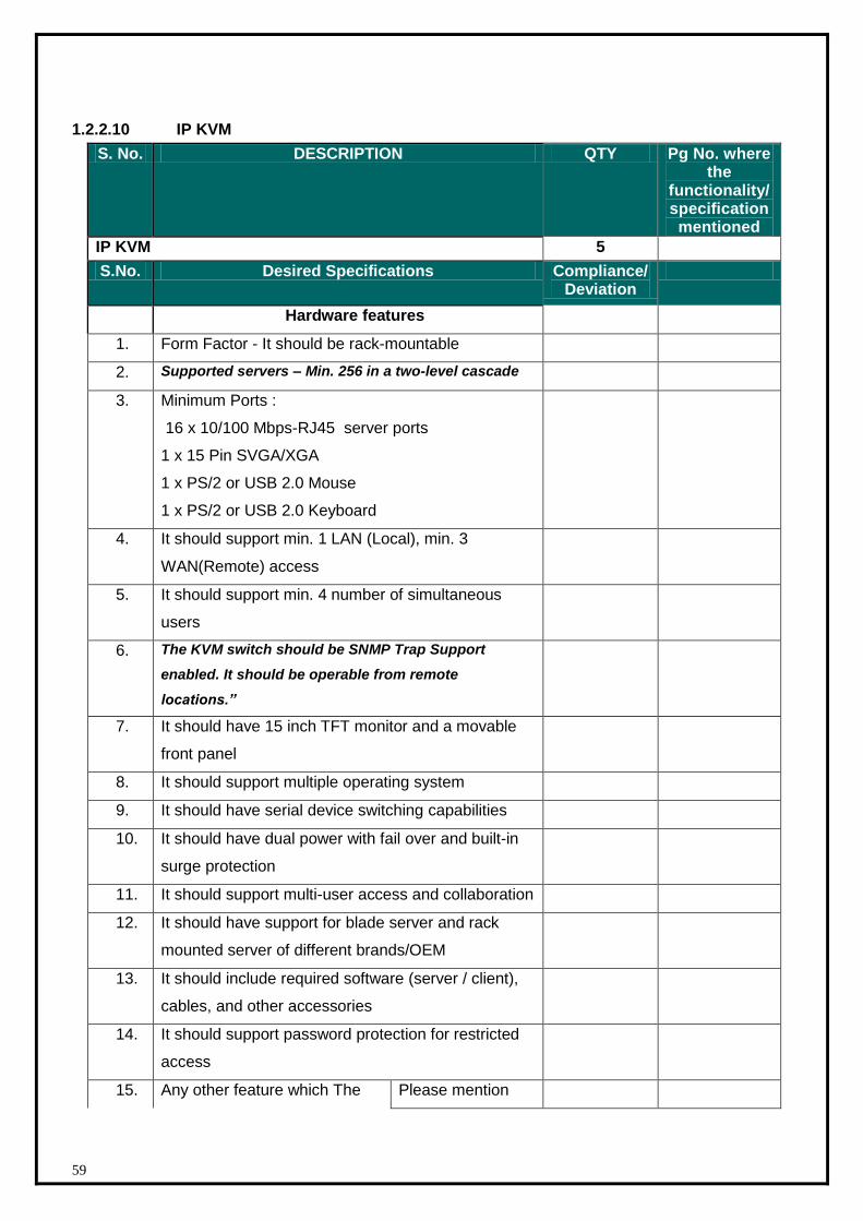
59
1.2.2.10 IP KVM
S. No. DESCRIPTION QTY Pg No. where the
functionality/ specification mentioned
IP KVM 5
S.No. Desired Specifications Compliance/ Deviation
Hardware features
1. Form Factor - It should be rack-mountable
2. Supported servers – Min. 256 in a two-level cascade
3. Minimum Ports :
16 x 10/100 Mbps-RJ45 server ports
1 x 15 Pin SVGA/XGA
1 x PS/2 or USB 2.0 Mouse
1 x PS/2 or USB 2.0 Keyboard
4. It should support min. 1 LAN (Local), min. 3
WAN(Remote) access
5. It should support min. 4 number of simultaneous
users
6. The KVM switch should be SNMP Trap Support
enabled. It should be operable from remote
locations.”
7. It should have 15 inch TFT monitor and a movable
front panel
8. It should support multiple operating system
9. It should have serial device switching capabilities
10. It should have dual power with fail over and built-in
surge protection
11. It should support multi-user access and collaboration
12. It should have support for blade server and rack
mounted server of different brands/OEM
13. It should include required software (server / client),
cables, and other accessories
14. It should support password protection for restricted
access
15. Any other feature which The Please mention

60
bidder wish to Mention here here: 1.
2.
3.
Adequate number of desktops,laptops, multifunction device which are required to make the
solution work would have to be included by the bidder.
61
1.2.3 Technical Specifications – IT Network Components
Following are different types of equipment configurations that shall be required for the State Data
Center (SDC).
Items and the configurations categorically mentioned below are the configurations required for the
Implementation of SDC network and security architecture. Any thing proposed by vendor over and
above the minimum required specs are acceptable; however, anything that is below the minimum
mentioned requirement even in a single specification may get the product disqualified.
The vendor has to include this as the part of the technical proposal with the make and model
numbers. The requirement of various components may be in phases.
The solution elements given by the bidder should comply with the specifications of various devices
mentioned below. Bidder shall have the responsibility to make to solution work and hence any
additional component might be required for the solution to work shall be provided by the bidder at
their own cost and within the implementation schedule. Also, the migration of IPv4 to IPv6 if required
by the state in future shall be done by the bidder at additional cost which shall be out of scope of this
RFP.
As per recommended and best practices, the components shall preferably be appliance based
(wherever applicable) and the intranet and internet firewalls shall be from different OEMs.
Provisioning of the internet bandwidth is the responsibility of the State government. DCO will only
liaison with the ISPs..
The bandwidth details are as under:
Denomination = 2x10 Mbps Internet bandwidth
Ratio = 1:1
End point type = SDC, RJ45
The DCO get the payment shall be made as per actual upon submission of periodical bills.
Manuals for configuring of switches, routers, firewall, IPS etc shall be provided by the selected
bidder.
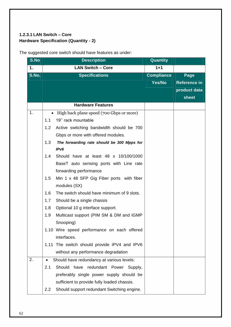
62
1.2.3.1 LAN Switch – Core
Hardware Specification (Quantity - 2)
The suggested core switch should have features as under:
S.No Description Quantity
1. LAN Switch – Core 1+1
S.No. Specifications Compliance
Yes/No
Page
Reference in
product data
sheet
Hardware Features
1 . High back plane speed (700 Gbps or more)
1.1 19’’ rack mountable
1.2 Active switching bandwidth should be 700
Gbps or more with offered modules.
1.3 The forwarding rate should be 300 Mpps for
IPv6
1.4 Should have at least 48 x 10/100/1000
BaseT auto sensing ports with Line rate
forwarding performance
1.5 Min 1 x 48 SFP Gig Fiber ports with fiber
modules (SX)
1.6 The switch should have minimum of 9 slots.
1.7 Should be a single chassis
1.8 Optional 10 g interface support.
1.9 Multicast support (PIM SM & DM and IGMP
Snooping)
1.10 Wire speed performance on each offered
interfaces.
1.11 The switch should provide IPV4 and IPV6
without any performance degradation
2 . Should have redundancy at various levels:
2.1 Should have redundant Power Supply,
preferably single power supply should be
sufficient to provide fully loaded chassis.
2.2 Should support redundant Switching engine.
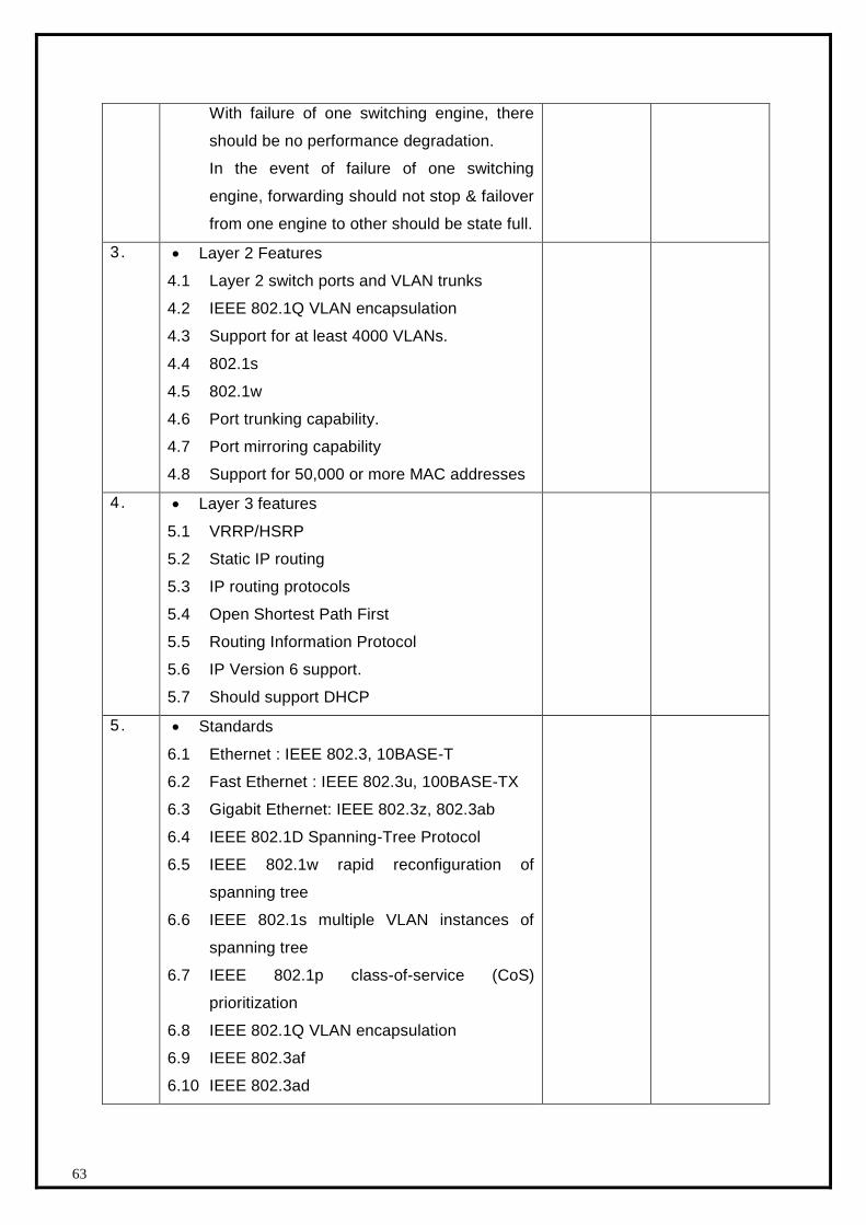
63
With failure of one switching engine, there
should be no performance degradation.
In the event of failure of one switching
engine, forwarding should not stop & failover
from one engine to other should be state full.
3 . Layer 2 Features
4.1 Layer 2 switch ports and VLAN trunks
4.2 IEEE 802.1Q VLAN encapsulation
4.3 Support for at least 4000 VLANs.
4.4 802.1s
4.5 802.1w
4.6 Port trunking capability.
4.7 Port mirroring capability
4.8 Support for 50,000 or more MAC addresses
4 . Layer 3 features
5.1 VRRP/HSRP
5.2 Static IP routing
5.3 IP routing protocols
5.4 Open Shortest Path First
5.5 Routing Information Protocol
5.6 IP Version 6 support.
5.7 Should support DHCP
5. Standards
6.1 Ethernet : IEEE 802.3, 10BASE-T
6.2 Fast Ethernet : IEEE 802.3u, 100BASE-TX
6.3 Gigabit Ethernet: IEEE 802.3z, 802.3ab
6.4 IEEE 802.1D Spanning-Tree Protocol
6.5 IEEE 802.1w rapid reconfiguration of
spanning tree
6.6 IEEE 802.1s multiple VLAN instances of
spanning tree
6.7 IEEE 802.1p class-of-service (CoS)
prioritization
6.8 IEEE 802.1Q VLAN encapsulation
6.9 IEEE 802.3af
6.10 IEEE 802.3ad
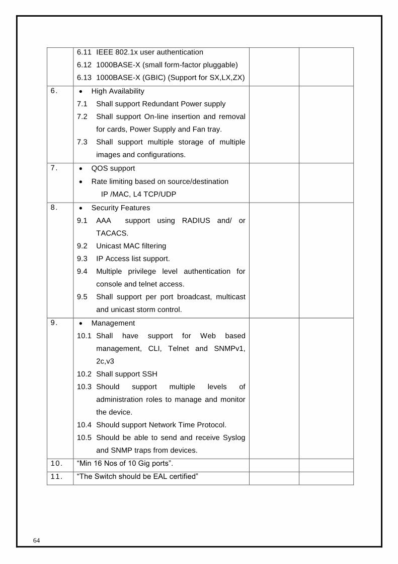
64
6.11 IEEE 802.1x user authentication
6.12 1000BASE-X (small form-factor pluggable)
6.13 1000BASE-X (GBIC) (Support for SX,LX,ZX)
6. High Availability
7.1 Shall support Redundant Power supply
7.2 Shall support On-line insertion and removal
for cards, Power Supply and Fan tray.
7.3 Shall support multiple storage of multiple
images and configurations.
7 . QOS support
Rate limiting based on source/destination
IP /MAC, L4 TCP/UDP
8. Security Features
9.1 AAA support using RADIUS and/ or
TACACS.
9.2 Unicast MAC filtering
9.3 IP Access list support.
9.4 Multiple privilege level authentication for
console and telnet access.
9.5 Shall support per port broadcast, multicast
and unicast storm control.
9 . Management
10.1 Shall have support for Web based
management, CLI, Telnet and SNMPv1,
2c,v3
10.2 Shall support SSH
10.3 Should support multiple levels of
administration roles to manage and monitor
the device.
10.4 Should support Network Time Protocol.
10.5 Should be able to send and receive Syslog
and SNMP traps from devices.
10. “Min 16 Nos of 10 Gig ports”.
11. “The Switch should be EAL certified”
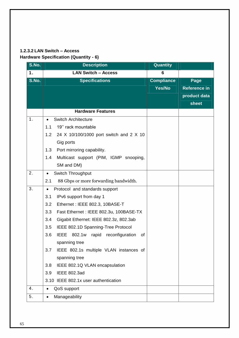
65
1.2.3.2 LAN Switch – Access
Hardware Specification (Quantity - 6)
S.No. Description Quantity
1. LAN Switch – Access 6
S.No. Specifications Compliance
Yes/No
Page
Reference in
product data
sheet
Hardware Features
1 . Switch Architecture
1.1 19’’ rack mountable
1.2 24 X 10/100/1000 port switch and 2 X 10
Gig ports
1.3 Port mirroring capability.
1.4 Multicast support (PIM, IGMP snooping,
SM and DM)
2 . Switch Throughput
2.1 88 Gbps or more forwarding bandwidth.
3 . Protocol and standards support
3.1 IPv6 support from day 1
3.2 Ethernet : IEEE 802.3, 10BASE-T
3.3 Fast Ethernet : IEEE 802.3u, 100BASE-TX
3.4 Gigabit Ethernet: IEEE 802.3z, 802.3ab
3.5 IEEE 802.1D Spanning-Tree Protocol
3.6 IEEE 802.1w rapid reconfiguration of
spanning tree
3.7 IEEE 802.1s multiple VLAN instances of
spanning tree
3.8 IEEE 802.1Q VLAN encapsulation
3.9 IEEE 802.3ad
3.10 IEEE 802.1x user authentication
4 . QoS support
5 . Manageability
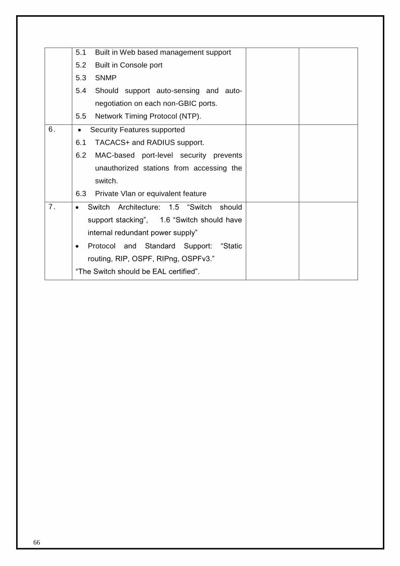
66
5.1 Built in Web based management support
5.2 Built in Console port
5.3 SNMP
5.4 Should support auto-sensing and auto-
negotiation on each non-GBIC ports.
5.5 Network Timing Protocol (NTP).
6 . Security Features supported
6.1 TACACS+ and RADIUS support.
6.2 MAC-based port-level security prevents
unauthorized stations from accessing the
switch.
6.3 Private Vlan or equivalent feature
7 . Switch Architecture: 1.5 “Switch should
support stacking”, 1.6 “Switch should have
internal redundant power supply”
Protocol and Standard Support: “Static
routing, RIP, OSPF, RIPng, OSPFv3.”
“The Switch should be EAL certified”.
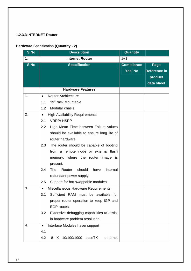
67
1.2.3.3 INTERNET Router
Hardware Specification (Quantity - 2)
S.No Description Quantity
1. Internet Router 1+1
S.No Specification Compliance
Yes/ No
Page
Reference in
product
data sheet
Hardware Features
1 . Router Architecture
1.1 19’’ rack Mountable
1.2 Modular chasis.
2 . High Availability Requirements
2.1 VRRP/ HSRP
2.2 High Mean Time between Failure values
should be available to ensure long life of
router hardware.
2.3 The router should be capable of booting
from a remote node or external flash
memory, where the router image is
present.
2.4 The Router should have internal
redundant power supply
2.5 Support for hot swappable modules
3 . Miscellaneous Hardware Requirements
3.1 Sufficient RAM must be available for
proper router operation to keep IGP and
EGP routes.
3.2 Extensive debugging capabilities to assist
in hardware problem resolution.
4 . Interface Modules have/ support
4.1
4.2 8 X 10/100/1000 baseTX ethernet
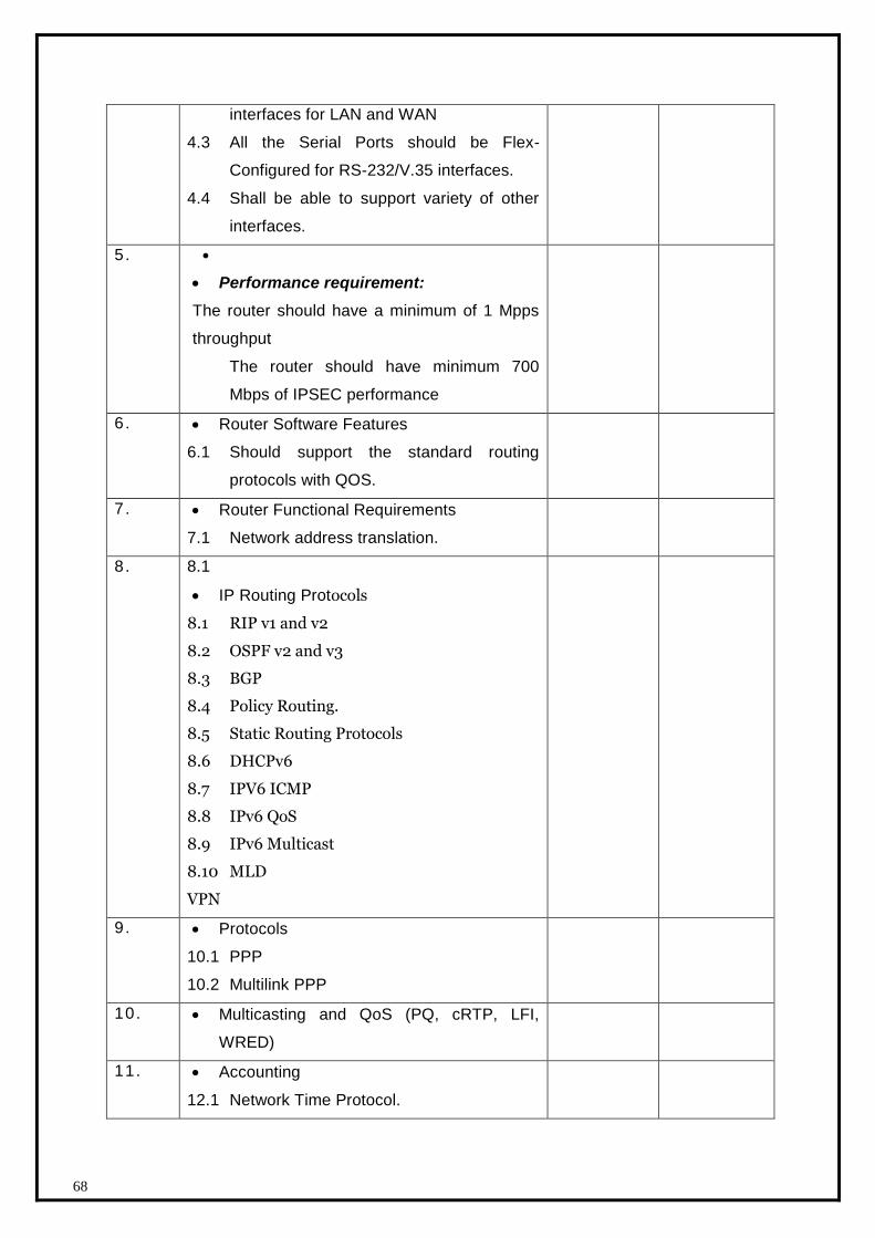
68
interfaces for LAN and WAN
4.3 All the Serial Ports should be Flex-
Configured for RS-232/V.35 interfaces.
4.4 Shall be able to support variety of other
interfaces.
5.
Performance requirement:
The router should have a minimum of 1 Mpps
throughput
The router should have minimum 700
Mbps of IPSEC performance
6 . Router Software Features
6.1 Should support the standard routing
protocols with QOS.
7 . Router Functional Requirements
7.1 Network address translation.
8 . 8.1
IP Routing Protocols
8.1 RIP v1 and v2
8.2 OSPF v2 and v3
8.3 BGP
8.4 Policy Routing.
8.5 Static Routing Protocols
8.6 DHCPv6
8.7 IPV6 ICMP
8.8 IPv6 QoS
8.9 IPv6 Multicast
8.10 MLD
VPN
9 . Protocols
10.1 PPP
10.2 Multilink PPP
10. Multicasting and QoS (PQ, cRTP, LFI,
WRED)
11. Accounting
12.1 Network Time Protocol.
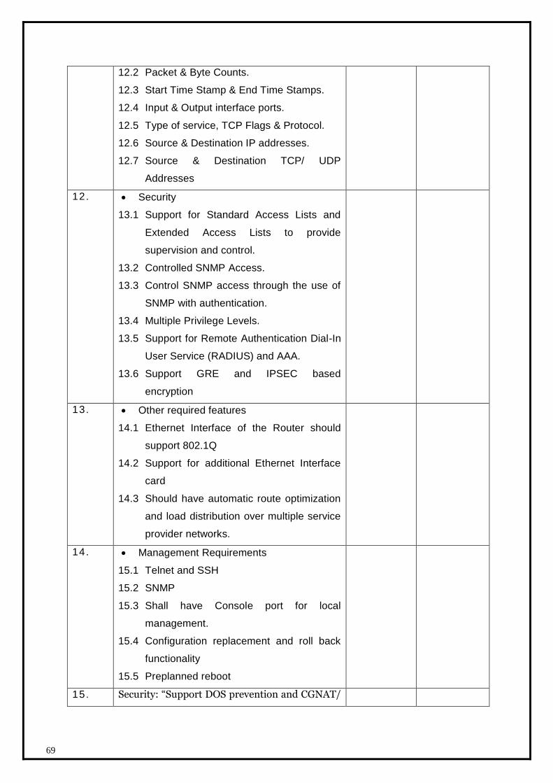
69
12.2 Packet & Byte Counts.
12.3 Start Time Stamp & End Time Stamps.
12.4 Input & Output interface ports.
12.5 Type of service, TCP Flags & Protocol.
12.6 Source & Destination IP addresses.
12.7 Source & Destination TCP/ UDP
Addresses
12. Security
13.1 Support for Standard Access Lists and
Extended Access Lists to provide
supervision and control.
13.2 Controlled SNMP Access.
13.3 Control SNMP access through the use of
SNMP with authentication.
13.4 Multiple Privilege Levels.
13.5 Support for Remote Authentication Dial-In
User Service (RADIUS) and AAA.
13.6 Support GRE and IPSEC based
encryption
13. Other required features
14.1 Ethernet Interface of the Router should
support 802.1Q
14.2 Support for additional Ethernet Interface
card
14.3 Should have automatic route optimization
and load distribution over multiple service
provider networks.
14. Management Requirements
15.1 Telnet and SSH
15.2 SNMP
15.3 Shall have Console port for local
management.
15.4 Configuration replacement and roll back
functionality
15.5 Preplanned reboot
15. Security: “Support DOS prevention and CGNAT/

70
Dual Stack”
16. “The Switch should be EAL certified”
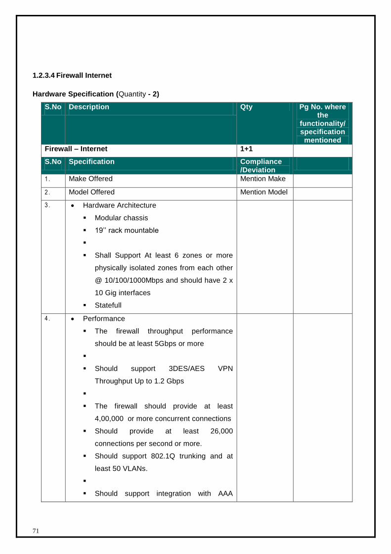
71
1.2.3.4 Firewall Internet
Hardware Specification (Quantity - 2)
S.No Description Qty Pg No. where the
functionality/ specification mentioned
Firewall – Internet 1+1
S.No Specification Compliance /Deviation
1 . Make Offered Mention Make
2 . Model Offered Mention Model
3 . Hardware Architecture
Modular chassis
19’’ rack mountable
Shall Support At least 6 zones or more
physically isolated zones from each other
@ 10/100/1000Mbps and should have 2 x
10 Gig interfaces
Statefull
4 . Performance
The firewall throughput performance
should be at least 5Gbps or more
Should support 3DES/AES VPN
Throughput Up to 1.2 Gbps
The firewall should provide at least
4,00,000 or more concurrent connections
Should provide at least 26,000
connections per second or more.
Should support 802.1Q trunking and at
least 50 VLANs.
Should support integration with AAA
72
server
Should have Application inspection for
standard applications like SSHv2,, FTP,
HTTP/HTTPS, ICMP, TCP,
Should support inbuilt support for IPSEC
VPNs with DES/ 3DES and AES support.
Firewall should support MD-5 and SHA-1
authentication
5 . Firewalling at layer 2 and layer 3 of the OSI
layer.
Static route, RIPv2, OSPF for routing
NAT and Port Address Translation feature
Should support IPv4 and IPv6.
Optional support to be able to detect,
respond to and report any unauthorized
activity.
6 . Firewall features shall include:
Application/Protocol Inspection Engines:
L2 transparent firewalling
Advanced HTTP Inspection Engine
Time-based ACLs or equivalent
7 . VPN feature shall support:
Support for n-tiered X.509 certificate
chaining
Manual X.509 certificate enrollment
(PKCS 10/7 support)
8 .
73
9 . High Availability
1 0 . Management
Embedded web based configuration /
management support.
Should have Management access through
console, SSH and GUI for managing the
firewall.
Should have the capability of restricting
the access through the Console and out-
of-band management interface to protect
the devices from local threats.
1 1 . Product shall be provided with all the required
licenses, software, management servers (Ref:
1.3.15) as applicable to meet all the above
mentioned specification.
1 2 . “Firewall should be ICSA/NSS/EAL certified.”
1.2.3.5 Intrusion Prevention System - Internet
Hardware Specifications (Quantity - 2)
S.No. Description Quantity
1. Intrusion Prevention System for Internet 1+1
S.No Specification Compliance
Yes/ No
Page
Reference in
product data
sheet
Hardware Features
1. The IPS should be appliance based and
should have the following Interfaces
1.1 “The IPS should have minimum of 2 pairs
of 10/100/1000 ports to support up to 4
inline protected segment support.”
74
1.2 1 Dedicated Management port
1.3 “2X 10 Gig populated.”
2 . Performance and Availability
2.1 The IPS device should provide an overall
throughput of at least 1 gbps or more
3 . Attack Detection Techniques
3.1 The IPS System should have the following
attack detection techniques
3.2 Vendors Signature Database of at least
1000 signatures.
3.3 Shall be able to support user defined
signatures.
3.4 Zero day attack protection using protocol
and traffic behavior analysis.
3.5 Backdoor Detection
3.6 DoS/ DDoS / SYN-flood/ TCP-flood /UDP-
flood
3.7 Monitoring of protocols such as TCP/IP,
ICMP, FTP etc.
4 . Action on Attacks
4.1 The IPS system should be able to do the
following in the event of detecting an
attack:
4.1.1 Block/Drop/Terminate attacks in real
time without logging.
4.1.2 Block/Drop/Terminate attacks in real
time and log.
4.1.3 Reset connections without logging.
4.1.4 Reset connections and log.
4.1.5 None (Log only)
5 . Other Capabilities
5.1 Should be capable of handling IPS
evasion techniques like fragmentation and
TCP reassembly etc.
5.2 Shall be able to support user defined
signatures, “Shall be able to perform

75
application based inspection.”
5.3 Shall be able to support automatic
signature updation from the OEM over the
internet using a secure communication
mechanism in the case of emergencies.
5.4 Default security Policy.
6. High Availability
6.1
6.2 “The device should support internal
redundant power supply”
6.3 It should support either active/passive or
active/active
7 . Deployment Modes
7.1 The IPS should be deployable in
Bridge/Transparent mode.
7.2 promiscuous / Inline mode
8 . Management and Monitoring Capabilities
8.1 The IPS Systems should have a
Management Console and remote telnet,
SSH and Web capabilities for basic
configuration of the device
8.2 The IPS should have a dedicated port for
Out-of-Band Management and should not
use any traffic ports for the management
purpose
8.3
8.4
8.5
8.6 The system should be able to support log
file, Syslog/SDEE and snmp.
8.7 Shall support role based administration for
various administrator and user levels.
8.8 “IPS should be ICSA/NSS/ EAL certified”
9 . Product shall be provided with all the
required licenses, management server
software as applicable to meet all the

76
above mentioned specification &
proposal.
77
1.2.3.6 End Point Protection for Servers and PCs (HIDS/ HIPS)
Bidder has to come up with number of licenses required and provide the same.
S.No Description Quantity
End Point Protection for Servers and PC’s in
the SDC (HIDS/ HIPS)
For all servers and PCs
supplied by DCO
S.No Specification Compliance
Yes/ No
Page Ref in
product
data sheet
Features
1 . Exploit Prevention
1.1 It should be able to Control applications,
services and programs to only allow
“good” behavior. This behavior-based,
proactive functionality protects against
day-zero threats. Buffer Overflow
prevention should be related to this
functionality also.
1.2 It should provide broad default policy set,
so that little policy editing is required for
deployment.
2 . Buffer Overflow Protection
2.1 It should provide protection against classic
buffer overflow memory attacks.
2.2 The Protection should be based on
behavior, not signatures, so that even
unknown buffer overflows are blocked.
3 . Application Firewall
3.1 It should be able to monitor and block
network traffic for threats.
4 . Out-of-the-Box Policies
4.1 It should contain a group of ready-to-run
protection policies for standard
applications and OS functions.
4.2 The default policies should provide
coverage for all applications when
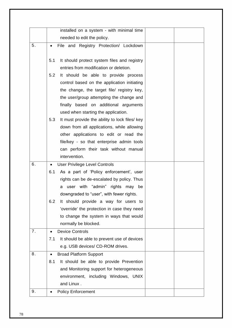
78
installed on a system - with minimal time
needed to edit the policy.
5. File and Registry Protection/ Lockdown
5.1 It should protect system files and registry
entries from modification or deletion.
5.2 It should be able to provide process
control based on the application initiating
the change, the target file/ registry key,
the user/group attempting the change and
finally based on additional arguments
used when starting the application.
5.3 It must provide the ability to lock files/ key
down from all applications, while allowing
other applications to edit or read the
file/key - so that enterprise admin tools
can perform their task without manual
intervention.
6 . User Privilege Level Controls
6.1 As a part of ‘Policy enforcement’, user
rights can be de-escalated by policy. Thus
a user with “admin” rights may be
downgraded to “user”, with fewer rights.
6.2 It should provide a way for users to
'override' the protection in case they need
to change the system in ways that would
normally be blocked.
7 . Device Controls
7.1 It should be able to prevent use of devices
e.g. USB devices/ CD-ROM drives.
8 . Broad Platform Support
8.1 It should be able to provide Prevention
and Monitoring support for heterogeneous
environment, including Windows, UNIX
and Linux .
9 . Policy Enforcement
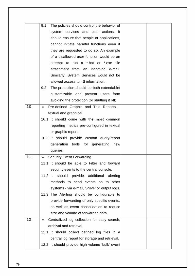
79
9.1 The policies should control the behavior of
system services and user actions, It
should ensure that people or applications,
cannot initiate harmful functions even if
they are requested to do so. An example
of a disallowed user function would be an
attempt to run a *.bat or *.exe file
attachment from an incoming e-mail.
Similarly, System Services would not be
allowed access to IIS information.
9.2 The protection should be both extendable/
customizable and prevent users from
avoiding the protection (or shutting it off).
10. Pre-defined Graphic and Text Reports –
textual and graphical
10.1 It should come with the most common
reporting metrics pre-configured in textual
or graphic reports.
10.2 It should provide custom query/report
generation tools for generating new
queries.
11. Security Event Forwarding
11.1 It should be able to Filter and forward
security events to the central console.
11.2 It should provide additional alerting
methods to send events on to other
systems - via e-mail, SNMP or output logs.
11.3 The Alerting should be configurable to
provide forwarding of only specific events,
as well as event consolidation to reduce
size and volume of forwarded data.
12. Centralized log collection for easy search,
archival and retrieval
12.1 It should collect defined log files in a
central log report for storage and retrieval.
12.2 It should provide high volume 'bulk' event
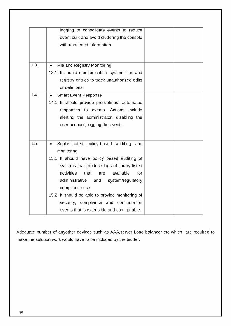
80
logging to consolidate events to reduce
event bulk and avoid cluttering the console
with unneeded information.
13. File and Registry Monitoring
13.1 It should monitor critical system files and
registry entries to track unauthorized edits
or deletions.
14. Smart Event Response
14.1 It should provide pre-defined, automated
responses to events. Actions include
alerting the administrator, disabling the
user account, logging the event..
15. Sophisticated policy-based auditing and
monitoring
15.1 It should have policy based auditing of
systems that produce logs of library listed
activities that are available for
administrative and system/regulatory
compliance use.
15.2 It should be able to provide monitoring of
security, compliance and configuration
events that is extensible and configurable.
Adequate number of anyother devices such as AAA,server Load balancer etc which are required to
make the solution work would have to be included by the bidder.
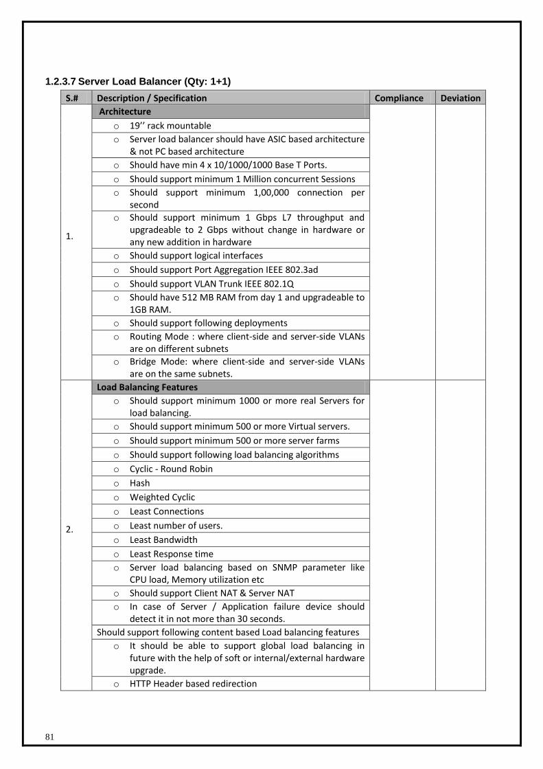
81
1.2.3.7 Server Load Balancer (Qty: 1+1)
S.# Description / Specification Compliance Deviation
1.
Architecture
o 19’’ rack mountable
o Server load balancer should have ASIC based architecture & not PC based architecture
o Should have min 4 x 10/1000/1000 Base T Ports.
o Should support minimum 1 Million concurrent Sessions
o Should support minimum 1,00,000 connection per second
o Should support minimum 1 Gbps L7 throughput and upgradeable to 2 Gbps without change in hardware or any new addition in hardware
o Should support logical interfaces
o Should support Port Aggregation IEEE 802.3ad
o Should support VLAN Trunk IEEE 802.1Q
o Should have 512 MB RAM from day 1 and upgradeable to 1GB RAM.
o Should support following deployments
o Routing Mode : where client-side and server-side VLANs are on different subnets
o Bridge Mode: where client-side and server-side VLANs are on the same subnets.
2.
Load Balancing Features
o Should support minimum 1000 or more real Servers for load balancing.
o Should support minimum 500 or more Virtual servers.
o Should support minimum 500 or more server farms
o Should support following load balancing algorithms
o Cyclic - Round Robin
o Hash
o Weighted Cyclic
o Least Connections
o Least number of users.
o Least Bandwidth
o Least Response time
o Server load balancing based on SNMP parameter like CPU load, Memory utilization etc
o Should support Client NAT & Server NAT
o In case of Server / Application failure device should detect it in not more than 30 seconds.
Should support following content based Load balancing features
o It should be able to support global load balancing in future with the help of soft or internal/external hardware upgrade.
o HTTP Header based redirection
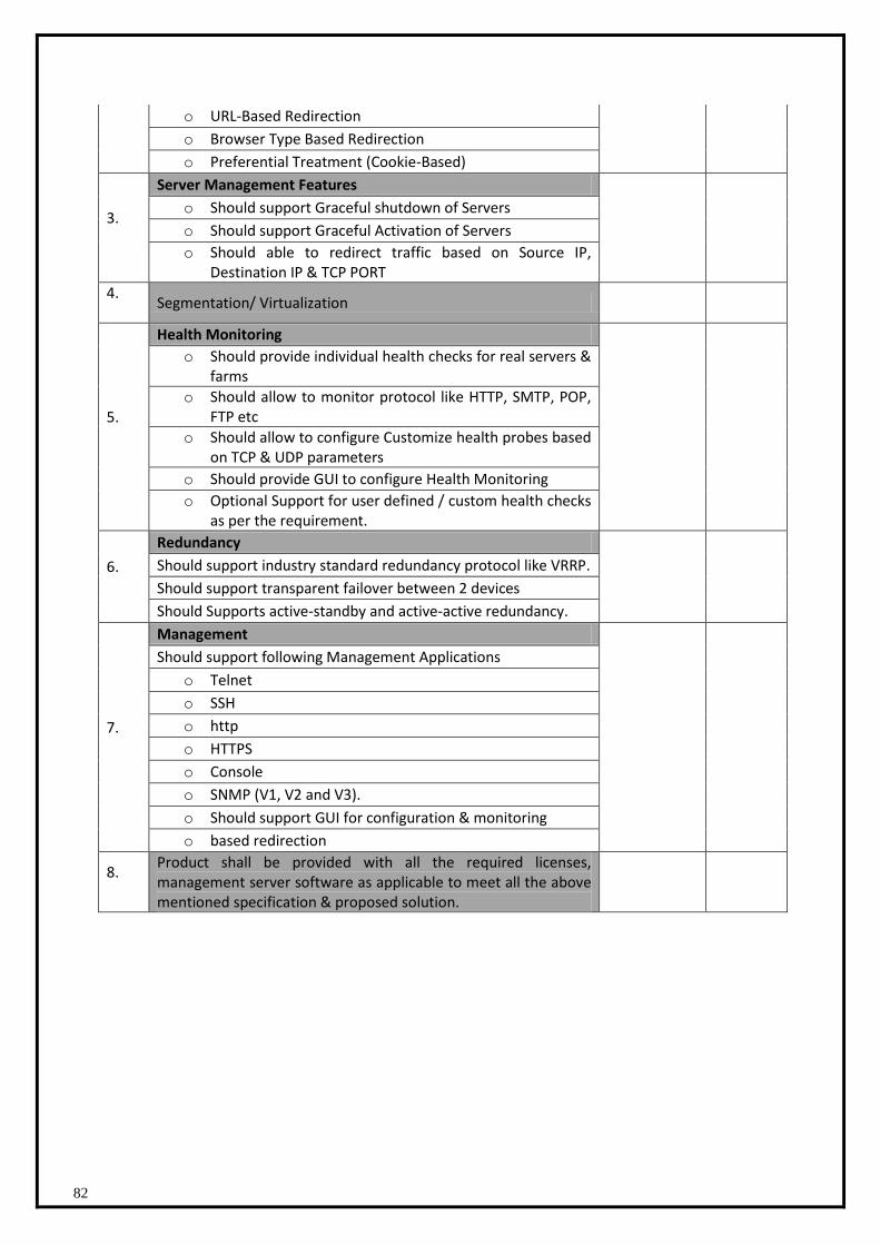
82
o URL-Based Redirection
o Browser Type Based Redirection
o Preferential Treatment (Cookie-Based)
3.
Server Management Features
o Should support Graceful shutdown of Servers
o Should support Graceful Activation of Servers
o Should able to redirect traffic based on Source IP, Destination IP & TCP PORT
4.
Segmentation/ Virtualization
5.
Health Monitoring
o Should provide individual health checks for real servers & farms
o Should allow to monitor protocol like HTTP, SMTP, POP, FTP etc
o Should allow to configure Customize health probes based on TCP & UDP parameters
o Should provide GUI to configure Health Monitoring
o Optional Support for user defined / custom health checks as per the requirement.
6.
Redundancy
Should support industry standard redundancy protocol like VRRP.
Should support transparent failover between 2 devices
Should Supports active-standby and active-active redundancy.
7.
Management
Should support following Management Applications
o Telnet
o SSH
o http
o HTTPS
o Console
o SNMP (V1, V2 and V3).
o Should support GUI for configuration & monitoring
o based redirection
8.
Product shall be provided with all the required licenses, management server software as applicable to meet all the above mentioned specification & proposed solution.
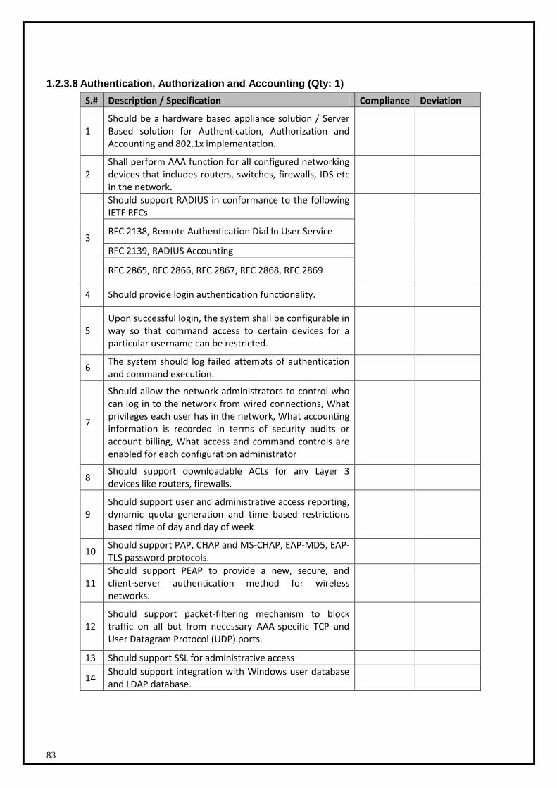
83
1.2.3.8 Authentication, Authorization and Accounting (Qty: 1)
S.# Description / Specification Compliance Deviation
1 Should be a hardware based appliance solution / Server Based solution for Authentication, Authorization and Accounting and 802.1x implementation.
2 Shall perform AAA function for all configured networking devices that includes routers, switches, firewalls, IDS etc in the network.
3
Should support RADIUS in conformance to the following IETF RFCs
RFC 2138, Remote Authentication Dial In User Service
RFC 2139, RADIUS Accounting
RFC 2865, RFC 2866, RFC 2867, RFC 2868, RFC 2869
4 Should provide login authentication functionality.
5 Upon successful login, the system shall be configurable in way so that command access to certain devices for a particular username can be restricted.
6 The system should log failed attempts of authentication and command execution.
7
Should allow the network administrators to control who can log in to the network from wired connections, What privileges each user has in the network, What accounting information is recorded in terms of security audits or account billing, What access and command controls are enabled for each configuration administrator
8 Should support downloadable ACLs for any Layer 3 devices like routers, firewalls.
9 Should support user and administrative access reporting, dynamic quota generation and time based restrictions based time of day and day of week
10 Should support PAP, CHAP and MS-CHAP, EAP-MD5, EAP-TLS password protocols.
11 Should support PEAP to provide a new, secure, and client-server authentication method for wireless networks.
12 Should support packet-filtering mechanism to block traffic on all but from necessary AAA-specific TCP and User Datagram Protocol (UDP) ports.
13 Should support SSL for administrative access
14 Should support integration with Windows user database and LDAP database.
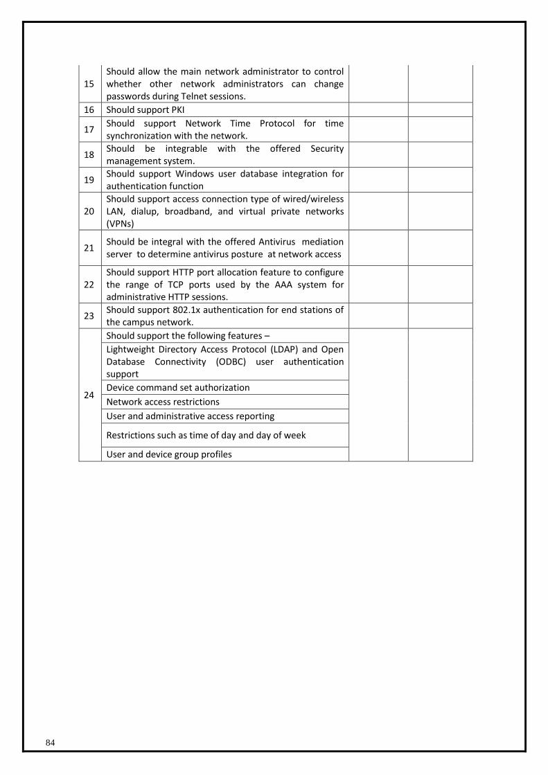
84
15 Should allow the main network administrator to control whether other network administrators can change passwords during Telnet sessions.
16 Should support PKI
17 Should support Network Time Protocol for time synchronization with the network.
18 Should be integrable with the offered Security management system.
19 Should support Windows user database integration for authentication function
20 Should support access connection type of wired/wireless LAN, dialup, broadband, and virtual private networks (VPNs)
21 Should be integral with the offered Antivirus mediation server to determine antivirus posture at network access
22 Should support HTTP port allocation feature to configure the range of TCP ports used by the AAA system for administrative HTTP sessions.
23 Should support 802.1x authentication for end stations of the campus network.
24
Should support the following features –
Lightweight Directory Access Protocol (LDAP) and Open Database Connectivity (ODBC) user authentication support
Device command set authorization
Network access restrictions
User and administrative access reporting
Restrictions such as time of day and day of week
User and device group profiles
85
1.2.4 SDC EMS Architecture
Enterprise Management System (EMS)
The proposed EMS solution should manage service availability of various citizen-centric
services hosted at Punjab SDC by identifying critical services, the infrastructure they depend
on and the relevant applications. The proposed solution should provide comprehensive and
end-to-end management of all the components for each service including Systems ,Database
and Application infrastructure.
.
1. Infrastructure Management System
(a).Network Fault Management:
- To provide comprehensive Event Management, Event Correlation, Root-cause Analysis for
any Network fault, Service Management including SLA monitoring etc. for the SDC
(b.)Performance Management
Perfromance Management System must monitor performance management across key parts of
the PUNJAB SDC infrastructure.Extended performance management console will be provided
to bidder .Bidder must integrate network & server performance information & alarms in a single
console & repository and thus provide a unified reporting interface for network ,server &
database components at SDC.
- The extended Network Performance Management consoles must provide a consistent
report generation interface at PUNJAB SDC for monitoring devices at SDC.Using central
console bidder should monitor & provide all required network performance reports (including
latency, threshold violations, packet errors, availability, bandwidth utilization etc.) for the
network infrastructure managed at SDC.
- Bidder should define necessary performance threshold for monitored devices at SDC using
extended NMS console and forward threshold exceptions to central fault management
console for centralized view of alarms generated.
- Bidder should monitor near real time performance of critical devices like bandwidth\cpu
utilization using extended performance management console.
- Bidder should configure & generate necessary Performance reports like At-A-Glance ,
Trend Reports , Top N Reports , What-If Reports , Service Level Reports , Health

86
Reports for monitored network devices ,servers & database using extended monitoring
consoles.
(i) Datacenter Network Traffic Analysis System
Analyzing network traffic pattern is very critical component to help in troubleshooting issues
related to network traffic congestion .Proposed tool should help in identifying type of traffic
flowing from SDC to SWAN & SWAN to SDC based on various applications & protocols for
capacity analysis and providing breakup of traffic utilization on critical interfaces.Tool should
help in identifying what application servers are generating maximum traffic in SDC thus
consuming most amount of bandwidth.Tools should provide following features
1. Tool should help in determining whether right traffic is flowing through or it is rogue traffic
which is not required.
2. The tool must support hetrogeneous Flow monitoring and traffic analysis for any of
technology vendors like NetFlow, J-Flow, sFlow, Net-stream, IPFIX technologies.
3. The solution should be of the type passive monitoring without a need to install any probe or
collector for data collection.
4. The proposed solution must be able to monitor and report on unique protocols per day and
display utilization data and baselines for each protocol individually by interface.
5. The proposed traffic analysis system must be capable of automatically detecting anomalous
behavior such as virus attacks or unauthorized application behavior. The system should
analyze all NetFlow traffic and alert via SNMP trap and syslog of any suspicious activity on
the network and send it to central network console.
6. Proposed tool must integrate with Central Network Fault & Performance Management
System seamlessly for sending alarms and context sensitive reporting.
7. The proposed traffic analysis system should provide visibility into new and unknown traffic
patterns which is critical for ensuring the performance of networked applications, as well as
identifying security risks. It should provide real-time analysis of traffic behavior in
infrastructure to help ensure network delivers application services reliably and securely.It
should provide Enterprise Network Behavior Summary for:
8. Fragmented Packet Sources, High Volume Sources, Packet Fan Out Sources,Syn/Rst only
sources,High Flow Sources,Number of TTL Expires
9. The solution must provide the following NetFlow based metrics:
10. Rate,Utilization,Byte Count,Flow Count,IP hosts with automatic DNS resolution,IP
conversation pairs with automatic DNS resolution,Router/interface with automatic SNMP
name resolution,Protocol breakdown by host, link, ToS or conversation,Utilization by bit
pattern matching of the TCP ToS field,AS number,BGP next hop address,IPv6 addresses
87
11. The proposed system must be capable of sending alerts via SNMP trap. Alerts should the
having the following configurable parameters:
12. The ability to choose any protocol, interface or group of interfaces, ToS ,rate, volume,
utilization, time filters (i.e. business hours) over a specified threshold being monitored by the
system.
13. Database Definition
13.1. The proposed solution must keep historical rate and protocol data for a minimum of 12
months (most recent) in its current long term operating database. All data in that database must
have a maximum 15 minute window granularity without roll up. A user must be able to select
any 15 minute window over the last 12 months and display unique utilization and protocol data
for every monitored interface.
13.2. The proposed solution must keep historical rate and protocol data for a minimum of 30
days (most recent) in its short term operating database. All data in that database must have a
maximum 1 minute window granularity. A user must be able to select any 1 minute window
over the last 30 days and display unique utilization and protocol data for every monitored
interface.
13.3. The proposed solution must be able to monitor and report on unique protocols per day
and display utilization data and baselines for each protocol individually by interface.
13.4. The proposed solution must keep and report on unique hosts and conversations per day
for each monitored interface.
13.5. The system must maintain this custom ToS based information for each interface for at
least 12 months at a minimum 15 minute granularity.
13.6. All custom reports from the long term database must support the ability to be run
manually or scheduled to run automatically at user selectable intervals.
13.7. All reports should be generated and displayed directly by the system from a common
interface.
13.8. The system should allow via API for Excel to download data to generate reports.
13.9. The system must be able to restrict views and access for defined users to specific
routers, interfaces, and reports.
14. The user must be able to generate reports from the long term database based on specific
thresholds defined by the user where the threshold can be compared to rate, utilization or
volume of every monitored interface as a filter for inclusion in the report.
15. Search for any traffic using a specific configurable destination port, or port range,
autonomous system (AS) number, BGP next hop IP address, ToS bit, clients or servers that
are experiencing more than a specified number of TCP resets per hour, IPv4 or IPv6
conversation bad IP Header, unreachable destination, TTL expired, traceroute requests,
MAC addresses, TCP flags, VLAN.

88
16. NetFlow collection device must support a minimum of 5 million flows per minute up to 9
million flows per minute and be capable of storing gathered information in a common
database where all long term reporting information is held.
17. The overview page must include an email function that provides a GUI driven method for
emailing the page in PDF format as well as for scheduling the email of this page at regular
intervals without user intervention to one or more recipients.
18. The system must provide the ability to group interfaces into functional groups based on any
user criteria. The grouping function must allow users to create group names and add
interfaces into that grouping for reporting purposes. Once created, these groups must be
available for selection within custom reports as a mechanism to include multiple interfaces
without individual selection for inclusion.
19. The system must support interface specific report generation for every monitored interface in
the network. It must provide menu or GUI driven access from the main system page that
allows users to select from the automatically generated interface list and navigate to
interface specific information.
20. This page should display a graph representing the total number of NetFlow flows that the
data was derived from. It must represent flows for the selected period of time, for this
interface.
21. The user must be able to easily change the data type of the main interface view from
protocol specific to a single graphical representation of utilization over multiple points in a 24
hour day as compared to all other similar points in the days in that month.
22. The monthly view must provide a graphical representation of the level of utilization for each
fifteen minute interval of each day of the month.
23. The user must be able to easily change the data type of the main interface view to a tabular
format showing the increase or decrease of traffic generated by that protocol as a
percentage using discrete least-squares approximation to find a best fit line of growth.
24. The proposed traffic analysis system should provide visibility into new and unknown traffic
patterns which is critical for ensuring the performance of networked applications, as well as
identifying security risks. It should provide real-time analysis of traffic behavior for every
client and server in infrastructure to help ensure network delivers application services
reliably and securely. Network behavior analysis should help in :
.1. Providing early insight into virus-infected hosts and worm attacks
.2. Identifying unauthorized or incorrectly configured server activity
.3. Alerting on unauthorized application deployments
.4. Identifying network misconfigurations, such as routing loops and inaccessible network
sources
.5. Reporting the sources of fragmented traffic
89
It should provide Enterprise Network Behavior Summary for:
Fragmented Packet Sources
High Volume Sources
Packet Fan Out Sources
Syn/Rst only sources
High Flow Sources
Number of TTL Expires
(iii) Server & Database Performance Management System
- All collected performance information for monitored servers must be stored in existing NMS
Performance Monitoring database.Bidder has to import/integrate server & database
performance monitoring data & alarms into existing NMS providing centralized performance
reporting & alarm information for monitored Network & Servers in one console.
- Monitored servers should be discovered in extended NMS console to provide topology view
of monitored network devices as well as servers depicting in topology what all servers are
connected to what all ports of monitored switches in SDC.
- The proposed tool should be able to monitor various operating system parameters such as
processors, memory, files, processes, file systems, etc. where applicable, using light
footprint agents on the servers to be monitored.
- The proposed tool should support operating system monitoring for various platforms
including Windows, UNIX and Linux.
- The proposed server monitoring solution should detect threshold violations in real-time,
sending an alert to the extended network fault management console .
- Proposed Performance Monitoring Solution must Provide At-A-Glance report for servers
monitored. The following charts must appear in reports for servers:
Availability ,CPU Utilization ,Disk Faults, Disk I/O ,File Cache Miss Rate ,Interface Utilization
,Latency ,Pages Paged ,Pages Swapped ,Physical Memory ,System Partition Utilization
,Total Packets ,User Partition Utilization ,Virtual Memory Utilization
- The Monitoring tool should support database performance agents for performance reporting
of standard RDBMs like Oracle, MS-SQL, Sybase and DB2.
- Database performance management solution for Distributed RDBMS must include hundreds
of predefined scans for monitoring various database, operating system and network
resources.
- Bidder should integrate Database performance monitoring solution with extended fault &
performance monitoring console in order to view database specific alarms & run
performance reporting from extended NMS consoles.
90
(c).Application Performance Management
Application Performance is very critical measure for PUNJAB SDC for monitoring critical citizen
centric applications accessed by external users. The proposed Application Performance
Management System at PUNJAB SDC must provide the following features:
- The proposed solution must determine if the root cause of performance issues is inside the
monitored application, in connected back-end systems or at the network layer from a single
console view.
- Bidder should integrate proposed APM tool with existing extended NMS Fault Management
console to forward application specific alarms & map them to application service definations
in NMS console.In event NMS received application performance alarm from APM tool it
should show impacted services and rasie a service degradation alarm depicting root cause
of service degradation is bad application performance This will help SDC operators to
identify that application service is degraded due to bad application performance & not at
network layer. This will help state in solving blame game problems between various
stakeholder to determine whether issue lies at network(SWAN) or at SDC infrastructure.
- The proposed solution should be able to proactively monitor all real user transactions; detect
failed transactions and help diagnosis of problems that affect user experience and prevent
completion of critical business processes.
- The proposed solution must provide deeper end-to-end transaction visibility by monitoring at
a transactional level and without deploying any software at end user desktop. The solution
must provide a single view that shows entire end-to-end real user transaction and breaks
down times spent within the application components, SQL statements, backend systems
and external 3rd party systems.
- Real time end user response monitoring & application performance diagnostic should be
tightly integrated out of the box without a need to perform extensive customizations.
- The proposed solution must be able to provide analysis of all problems and find root-cause
for problems showing the problematic areas within the application infrastructure..
- The proposed solution must be able to detect production Memory Leaks from mishandled
Java Collections and isolate exact component creating leaking Collection.
- The proposed solution must allow monitoring granularity of no more than 15 seconds for all
transactions.
- The proposed solution must provide real-time monitoring of resource utilization like JVM
memory usage, Servlets, EJB pools, DB connection pools and Threads.

91
- The proposed solution must tie SQL statements to components involved, i.e. SQL queries
should be able to get correlated to the Java components calling them. This should be clearly
visible by showing the transaction call stack ("Blame stack").
- The proposed solution must identify any changes to application configuration files(.xml,
properties etc), File system or application code and be able to correlate changes to
application performance dynamically in production environments.
- The proposed solution must proactively identify any thread usage problems within
applications and identify stalled (stuck) threads. The proposed solution must also monitor
web services across multiple processes (cross JVM tracing)
- The proposed solution should allow access to performance data both using a Graphical user
interface (GUI) and over the web (web based access) and provide ability to monitor
performance of applications up to the method level of execution (Java/.Net method) 24x7 in
production environments with negligible impact on monitored application.
- The proposed solution must provide for dynamic instrumentation of application code, i.e.
enhance be able out of the box monitoring with extra monitoring definitions without having to
restart application.
- The proposed solution should measure the end users' experiences based on transactions
without necessitating installation of client agents / probes on end-user desktops. · The
proposed solution should measure the end users' experiences based on real user
transactions & not synthetic or robotic transactions generated without. The solution should
be an appliance-based system acting as a passive listener on the network thus inducing
zero overhead on the network and application layer.
- The proposed system must be able to detect user impacting defects and anomalies and
reports them in real-time. The proposed system must also be able to provide user usage
analysis and show how user's success rate, average time and transaction count has
changed over a specific period of time such as current week versus previous week.
- The proposed system must be able to pro-actively determine exactly which real users were
impacted by transaction defects, their location and status.
- The proposed system must be able to provide the ability to detect and alert when users
experience HTTP error codes such as 404 errors or errors coming from the web application.
- The proposed system must allow to dynamically instrument components of transactions
revealed in a trace session without restarting the Java Virtual Machine (JVM).
-
- The solution must show out of the box application triage maps that allow to instantly grasp
the layout of the applications in the environment in a visual manner to help identify and
triage current and emerging problems.
92
- The solution should have provision for automatic transaction discovery, for example by
setting up some bounding parameters to describe transactions like the web site, the
language, and parameters (such as post, query, and cookies).
- The proposed solution must provide a single view that shows entire end-to-end real user
transaction and breaks down times spent within the J2EE application components, SQL
statements, backend systems, industry standard databases and external 3rd party systems.
- The proposed solution must gather available performance indicator metrics from all within
real-time production environments and real user transactions 24x7 with minimal overhead
on monitored applications
- The proposed solution must provide means to integrate monitoring data with SNMP/TCPIP
managers.
- The proposed solution must be able to monitor application performance to all connected
backend systems and supporting external systems within the application.
- All application stakeholders (i.e. DBA, Operation and application developers) must get
performance data pertaining to their specific areas from Java/.Net application agent within
the application server
- The proposed application performance management solution must support monitoring of
various industry standard application servers like JBOSS Application Server ver 4.23 and
above.
(d.)Helpdesk Management System
Proposed Helpdesk Management software at SDC should integrate with existing helpdesk
running at SWAN in order to provide State complete status of issues, incidents, service level
violations and their resolution time for both SWAN & SDC infrastructure in a single helpdesk
console.Bidder should create separate view for SDC operator to log & view SDC incidents.
- The proposed helpdesk solution must provide flexibility of logging, viewing, updating and
closing incident manually via web interface.
- The proposed helpdesk solution must support ITIL processes like request management,
problem management, configuration management and change order management with out-
of-the-box templates for various ITIL service support porcesses.
- Each escalation policy must allow easy definition on multiple escalation levels and
notification to different personnel via window GUI/console .
- The proposed helpdesk solution must have an updateable knowledge base for technical
analysis and further help end-users to search solutions for previously solved issues.
- The proposed helpdesk solution must support tracking of SLA (service level agreements) for
call requests within the help desk through service types.
93
- The proposed helpdesk solution must integrate tightly with the Knowledge tools and CMDB
and should be accessible from the same login window.
- The proposed helpdesk solution must allow the IT team to see the CI relationships in
pictorial format, with a specified number of relationships on single window.
- The proposed helpdesk solution must have a built-in workflow engine. The proposed
helpdesk solution must support Non-linear workflows with decision based branching and the
ability to perform parallel processing. It should also have a graphical workflow designer with
drag & drop feature for workflow creation and updates.
- The proposed helpdesk solution must have an integrated CMDB for better configuration
management & change management process. CMDB should have more then 50 CI families,
140 CI Classes and 70 CI Relationship Types out of the box. Both Service Desk & CMDB
should have same login window.
- It should support remote management for end-user & allow analysts to do the desktop
sharing for any system located anywhere, just connected to internet.
- Remote desktop sharing in Service desk tool should be agent less & all activity should be
automatically logged into the service desk ticket.
- Proposed helpdesk must be certified on all 14 ITIL v3 processes by certifying agencies like
pink elephant.
(e).Host based Access Control for securing critical datacenter servers
- Host based security solution must allow controlling of access to system resources including
data files, devices, processes/daemons and audit files.
- The solution should Self-protect itself – Must be able to prevent hackers with root access
from circumventing or shutting down the security engine. Must use a self-protected
database for storing all security information.
- The solution should provide Rights Delegation - Must provide the ability to designate specific
users as Administrators, Auditors, and Password Managers etc with appropriate rights. Must
also provide the ability to designate specific users as Subordinate or Group Administrators,
to manage users and file permissions for their Group
- The solution should support cross platform Management – Must support management and
policy distribution across Windows, Linux and Unix platforms from a central management
console. It must support the deployment of the same policies across multiple servers
ensuring consistency of security policies across machines in the enterprise.
- The solution must provide capability to allow access to sensitive resources only through
approved programs.
94
- Administrators must be able to define critical files that are not supposed to change. If these
files are modified, the process that checks the sensitive files must find that the files have
changed and write an audit record.
- The solution should allow protection of files on even non-NTFS file systems like FAT and
CDFS.
- The solution must provide support for IPv6 and FIPS140-2 and must provide Services and
Registry Values Protection on Windows
- The solution must provide administrative password checkout function. It should provide
workflow for requesting and checking out a system-generated. The solution should provide
the functionality to force the user to check the password in once their task is completed, or
PUPM should provide the capability to be configured to automatically check the password in
after a specific time period; and it can be a manually forced check in as well.
- The privilege user password management (PUPM) must provide a fully functional and
customizable workflow that provides common out-of-the-box use cases for PUPM. The
solution must provide a break glass feature. A break glass scenario occurs when a
privileged user needs immediate access to an account that they are not authorized to
manage. Break glass accounts are privileged accounts that are not assigned to the user
according to their role. However, the user can obtain the account password immediately,
without approval, if the need arises. This eliminates the possibility of a delay for an admin to
approve the request. All transactions related to the break glass scenario must securely be
logged for audit purposes.
- The solution should provide a feature to eliminate passwords from scripts. Via PUPM, it
should be possible to replace hard-coded passwords in scripts with privileged account
passwords that are generated by PUPM only when needed.
- The solution should provide a unified web based console which consolidates all aspects of
privileged user management under a single console — host access control and privileged
user management across physical and virtual systems, devices and applications.
- The PUPM must support a wide range of virtualization platforms including but not limited to:
VMware ESX, Solaris 10 Zones, LDOMs, Microsoft Hyper-v, IBM VIO, AIX LPAR, HP-UX
VPAR, Linux Xen and Mainframe x/VM, providing for more consistent security management
of access control risks across these virtual partitions, in addition to physical platforms.
EMS Integration Points
- Network fault management system should attach an asset identifier when submitting a
helpdesk ticket. In case the asset is not found in the helpdesk database, it should be
automatically created prior to submitting the ticket.
95
- When certain user tries to make any change on network device through fault management
console a helpdesk ticket should be generated automatically.The Service Desk operator
must have the ability to view the proposed configuration change .Once the ticket is
approved the admin is automatically notified and is able to proceed with the change.
- The existing Fault Management Solution must support integration with helpdesk or trouble
ticketing system such that integration should Associates alarms with Service Desk tickets in
the following ways:
o Manually creates tickets when requested by Fault Management GUI operators
o Automatically creates tickets based on alarm type
o Provides a link to directly launch a Service Desk view of a particular ticket created by
alarm from within the Network Operation console.
o Maintains the consistency of the following information that is shared between alarm and
its associated Service Desk ticket including status of alarms and associated tickets and
current assignee assigned to tickets.
- Helpdesk ticket number created for associated alarm should be visible inside Network
Operation Console . Helpdesk incident can be launched once clicked on ticket number for
associated alarm from with in Network Operation Conole.
- SLA’s violation on monitored application end user response time must open a helpdesk
incident out of the box.
- Bidder should integrate NMS consoles to provide unified workflow between the fault and
performance management systems including bi-directional and context-sensitive
navigation, such as
Navigate from the Topology View to At-a-Glance or Trend Reports for any asset
Navigate from the Alarm View to At-a-Glance, Trend or Alarm Detail Reports
- Bidder should integrate existing NMS at PAWAN with additional Application ,Server &
Database,helpdesk monitoring tools proosed at SDC in order to provide single unified view
of monitored SDC infrastructure .Bidder should define application service at NMS & map
Application , Server & Database Performance alarms from SDC monitoring tools to
application service definition at existing NMS console at PAWAN . This will help state level
operator to pin point if hosted SDC Application service outage is due to bad application
performance or due to bad hosting server\database performance\availability or due to bad
SWAN or SDC network performance\faults. This will help state to pin point root cause of
application service outage by identifying which component is impacting and hence come out
of blame game whether problem is at SDC level or at SWAN level.
1. Host-based OS Access Control System
96
The proposed Host-based Server Access Control Solution should be able to protect critical
server infrastructure in the SDC environment and minimize security risks by regulating access to
confidential data and mission critical services. The solution should provide policy-based control
of who can access specific systems, what they can do within them, and when they are allowed
access for all servers within the SDC. Specifically, it should proactively secure access to data
and applications located on Windows ,Linux, UNIX and system servers throughout the proposed
SDC infrastructure.
Host based security solution must allow controlling of access to system resources including data
files, devices, processes/daemons and audit files.
The solution should intercept security-sensitive events in real-time, and evaluate its validity
before passing control to the OS.
The solution should be Non-Intrusive – Must make no changes to the operating system kernel
or binaries. Software must allow for quick uninstall if necessary.
- The solution should Self-protect itself – Must be able to prevent hackers with root access from
circumventing or shutting down the security engine. Must use a self-protected database for
storing all security information.
The solution should provide Rights Delegation - Must provide the ability to designate specific
users as Administrators, Auditors, and Password Managers etc with appropriate rights. Must
also provide the ability to designate specific users as Subordinate or Group Administrators, to
manage users and file permissions for their Group
The solution should support cross platform Management – Must support management and
policy distribution across Windows, Linux and UNIX platforms from a central management
console. It must support the deployment of the same policies across multiple servers ensuring
consistency of security policies across machines in the enterprise.
The solution must provide capability to allow access to sensitive resources only through
approved programs.
The solution should provide Process Controls - Administrator must be able to control the
circumstances, under which authorized users may terminate sensitive processes (daemons),
including time and day, where from, etc.
The solution should prevent tampering of audit files by anyone while it is running on the
machine. Additionally, any change of rules should always be audited.
The solution must provide a warning mode that can be used during implementation to verify
policies and their impact before deployment.
The solution should allow protection of files on even non-NTFS file systems like FAT and CDFS.
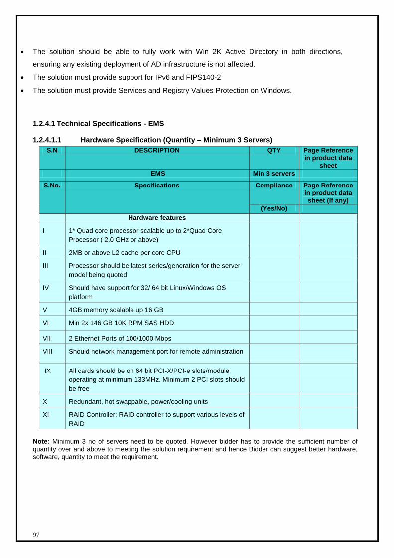
97
The solution should be able to fully work with Win 2K Active Directory in both directions,
ensuring any existing deployment of AD infrastructure is not affected.
The solution must provide support for IPv6 and FIPS140-2
The solution must provide Services and Registry Values Protection on Windows.
1.2.4.1 Technical Specifications - EMS
1.2.4.1.1 Hardware Specification (Quantity – Minimum 3 Servers)
S.N DESCRIPTION QTY Page Reference in product data
sheet
EMS Min 3 servers
S.No. Specifications Compliance Page Reference in product data sheet (If any)
(Yes/No)
Hardware features
I 1* Quad core processor scalable up to 2*Quad Core
Processor ( 2.0 GHz or above)
II 2MB or above L2 cache per core CPU
III Processor should be latest series/generation for the server
model being quoted
IV Should have support for 32/ 64 bit Linux/Windows OS
platform
V 4GB memory scalable up 16 GB
VI Min 2x 146 GB 10K RPM SAS HDD
VII 2 Ethernet Ports of 100/1000 Mbps
VIII Should network management port for remote administration
IX All cards should be on 64 bit PCI-X/PCI-e slots/module
operating at minimum 133MHz. Minimum 2 PCI slots should
be free
X Redundant, hot swappable, power/cooling units
XI RAID Controller: RAID controller to support various levels of
RAID
Note: Minimum 3 no of servers need to be quoted. However bidder has to provide the sufficient number of quantity over and above to meeting the solution requirement and hence Bidder can suggest better hardware, software, quantity to meet the requirement.
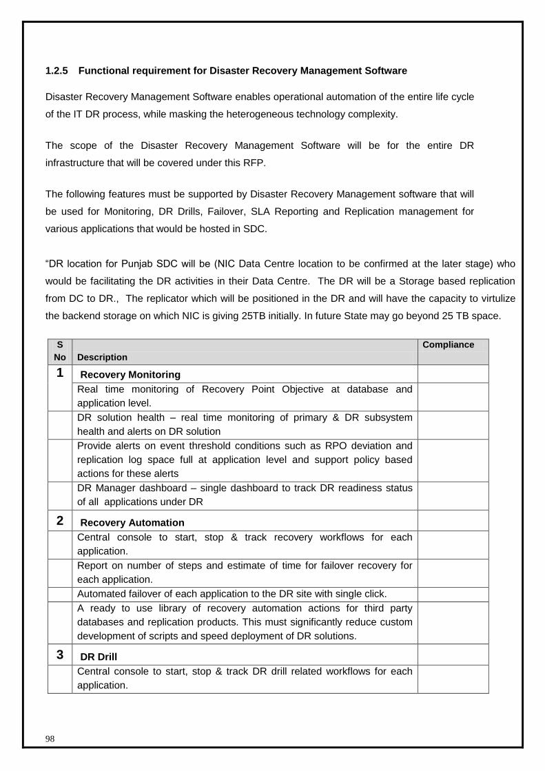
98
1.2.5 Functional requirement for Disaster Recovery Management Software
Disaster Recovery Management Software enables operational automation of the entire life cycle
of the IT DR process, while masking the heterogeneous technology complexity.
The scope of the Disaster Recovery Management Software will be for the entire DR
infrastructure that will be covered under this RFP.
The following features must be supported by Disaster Recovery Management software that will
be used for Monitoring, DR Drills, Failover, SLA Reporting and Replication management for
various applications that would be hosted in SDC.
“DR location for Punjab SDC will be (NIC Data Centre location to be confirmed at the later stage) who
would be facilitating the DR activities in their Data Centre. The DR will be a Storage based replication
from DC to DR., The replicator which will be positioned in the DR and will have the capacity to virtulize
the backend storage on which NIC is giving 25TB initially. In future State may go beyond 25 TB space.
S
No Description
Compliance
1 Recovery Monitoring
Real time monitoring of Recovery Point Objective at database and
application level.
DR solution health – real time monitoring of primary & DR subsystem
health and alerts on DR solution
Provide alerts on event threshold conditions such as RPO deviation and
replication log space full at application level and support policy based
actions for these alerts
DR Manager dashboard – single dashboard to track DR readiness status
of all applications under DR
2 Recovery Automation
Central console to start, stop & track recovery workflows for each
application.
Report on number of steps and estimate of time for failover recovery for
each application.
Automated failover of each application to the DR site with single click.
A ready to use library of recovery automation actions for third party
databases and replication products. This must significantly reduce custom
development of scripts and speed deployment of DR solutions.
3 DR Drill
Central console to start, stop & track DR drill related workflows for each
application.
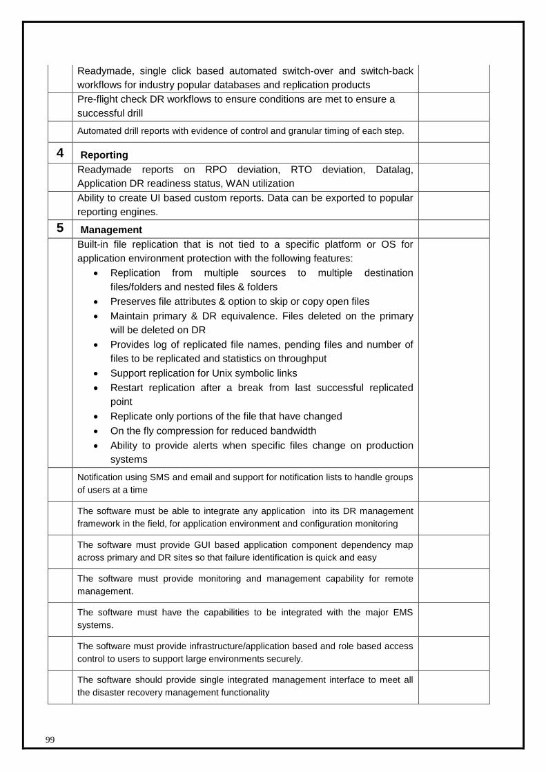
99
Readymade, single click based automated switch-over and switch-back
workflows for industry popular databases and replication products
Pre-flight check DR workflows to ensure conditions are met to ensure a
successful drill
Automated drill reports with evidence of control and granular timing of each step.
4 Reporting
Readymade reports on RPO deviation, RTO deviation, Datalag,
Application DR readiness status, WAN utilization
Ability to create UI based custom reports. Data can be exported to popular
reporting engines.
5 Management
Built-in file replication that is not tied to a specific platform or OS for
application environment protection with the following features:
Replication from multiple sources to multiple destination
files/folders and nested files & folders
Preserves file attributes & option to skip or copy open files
Maintain primary & DR equivalence. Files deleted on the primary
will be deleted on DR
Provides log of replicated file names, pending files and number of
files to be replicated and statistics on throughput
Support replication for Unix symbolic links
Restart replication after a break from last successful replicated
point
Replicate only portions of the file that have changed
On the fly compression for reduced bandwidth
Ability to provide alerts when specific files change on production
systems
Notification using SMS and email and support for notification lists to handle groups
of users at a time
The software must be able to integrate any application into its DR management
framework in the field, for application environment and configuration monitoring
The software must provide GUI based application component dependency map
across primary and DR sites so that failure identification is quick and easy
The software must provide monitoring and management capability for remote
management.
The software must have the capabilities to be integrated with the major EMS
systems.
The software must provide infrastructure/application based and role based access
control to users to support large environments securely.
The software should provide single integrated management interface to meet all
the disaster recovery management functionality
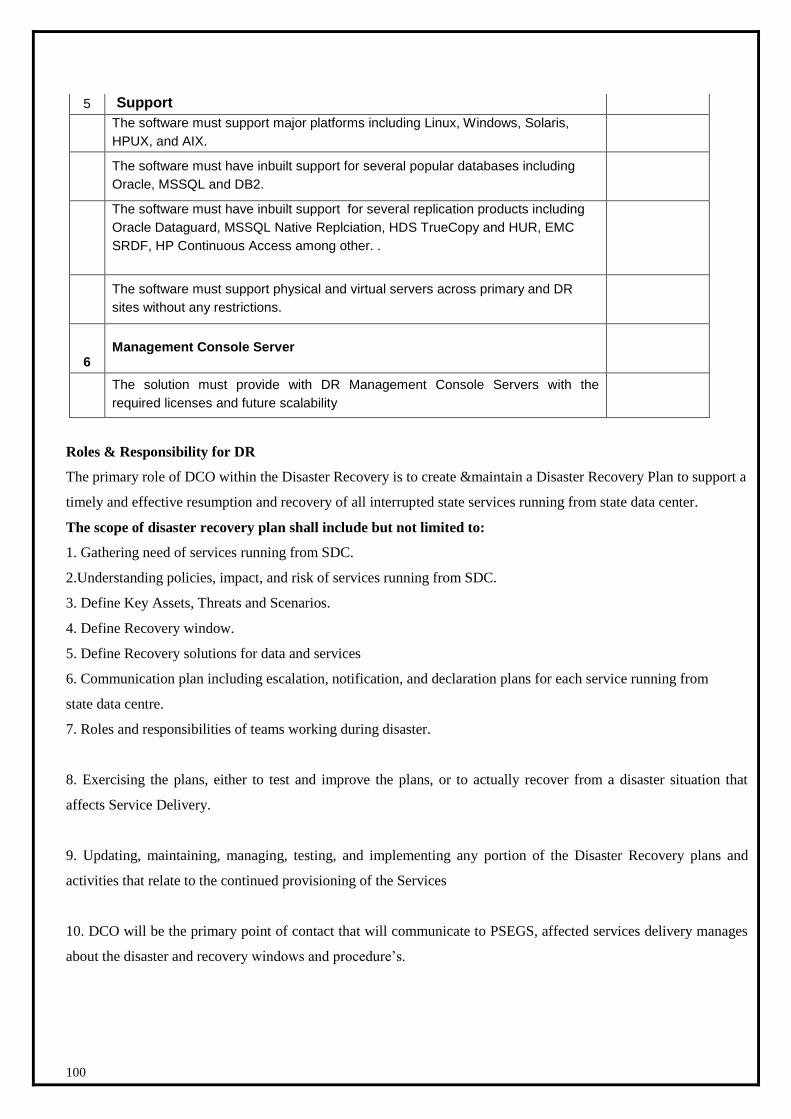
100
5 Support
The software must support major platforms including Linux, Windows, Solaris,
HPUX, and AIX.
The software must have inbuilt support for several popular databases including
Oracle, MSSQL and DB2.
The software must have inbuilt support for several replication products including
Oracle Dataguard, MSSQL Native Replciation, HDS TrueCopy and HUR, EMC
SRDF, HP Continuous Access among other. .
The software must support physical and virtual servers across primary and DR
sites without any restrictions.
6 Management Console Server
The solution must provide with DR Management Console Servers with the
required licenses and future scalability
Roles & Responsibility for DR
The primary role of DCO within the Disaster Recovery is to create &maintain a Disaster Recovery Plan to support a
timely and effective resumption and recovery of all interrupted state services running from state data center.
The scope of disaster recovery plan shall include but not limited to:
1. Gathering need of services running from SDC.
2.Understanding policies, impact, and risk of services running from SDC.
3. Define Key Assets, Threats and Scenarios.
4. Define Recovery window.
5. Define Recovery solutions for data and services
6. Communication plan including escalation, notification, and declaration plans for each service running from
state data centre.
7. Roles and responsibilities of teams working during disaster.
8. Exercising the plans, either to test and improve the plans, or to actually recover from a disaster situation that
affects Service Delivery.
9. Updating, maintaining, managing, testing, and implementing any portion of the Disaster Recovery plans and
activities that relate to the continued provisioning of the Services
10. DCO will be the primary point of contact that will communicate to PSEGS, affected services delivery manages
about the disaster and recovery windows and procedure’s.
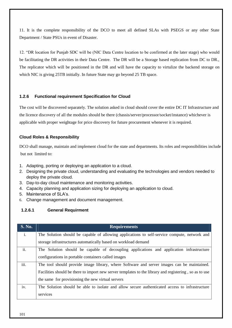
101
11. It is the complete responsibility of the DCO to meet all defined SLAs with PSEGS or any other State
Department / State PSUs in event of Disaster.
12. “DR location for Punjab SDC will be (NIC Data Centre location to be confirmed at the later stage) who would
be facilitating the DR activities in their Data Centre. The DR will be a Storage based replication from DC to DR.,
The replicator which will be positioned in the DR and will have the capacity to virtulize the backend storage on
which NIC is giving 25TB initially. In future State may go beyond 25 TB space.
1.2.6 Functional requirement Specification for Cloud
The cost will be discovered separately. The solution asked in cloud should cover the entire DC IT Infrastructure and
the licence discovery of all the modules should be there (chassis/server/processor/socket/instance) whichever is
applicable with proper weightage for price discovery for future procurement whenever it is required.
Cloud Roles & Responsibility
DCO shall manage, maintain and implement cloud for the state and departments. Its roles and responsibilities include
but not limited to:
1. Adapting, porting or deploying an application to a cloud.
2. Designing the private cloud, understanding and evaluating the technologies and vendors needed to
deploy the private cloud.
3. Day-to-day cloud maintenance and monitoring activities.
4. Capacity planning and application sizing for deploying an application to cloud.
5. Maintenance of SLA’s.
6. Change management and document management.
1.2.6.1 General Requirment
S. No. Requirements
i. The Solution should be capable of allowing applications to self-service compute, network and
storage infrastructures automatically based on workload demand
ii. The Solution should be capable of decoupling applications and application infrastructure
configurations in portable containers called images
iii. The tool should provide image library, where Software and server images can be maintained.
Facilities should be there to import new server templates to the library and registering , so as to use
the same for provisioning the new virtual servers
iv. The Solution should be able to isolate and allow secure authenticated access to infrastructure
services
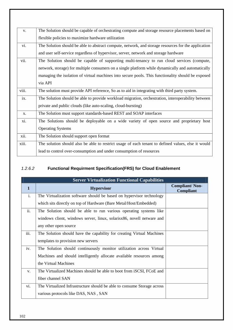
102
v. The Solution should be capable of orchestrating compute and storage resource placements based on
flexible policies to maximize hardware utilization
vi. The Solution should be able to abstract compute, network, and storage resources for the application
and user self-service regardless of hypervisor, server, network and storage hardware
vii. The Solution should be capable of supporting multi-tenancy to run cloud services (compute,
network, storage) for multiple consumers on a single platform while dynamically and automatically
managing the isolation of virtual machines into secure pools. This functionality should be exposed
via API
viii. The solution must provide API reference, So as to aid in integrating with third party system.
ix. The Solution should be able to provide workload migration, orchestration, interoperability between
private and public clouds (like auto-scaling, cloud-bursting)
x. The Solution must support standards-based REST and SOAP interfaces
xi. The Solutions should be deployable on a wide variety of open source and proprietary host
Operating Systems
xii. The Solution should support open format
xiii. The solution should also be able to restrict usage of each tenant to defined values, else it would
lead to control over-consumption and under consumption of resources
1.2.6.2 Functional Requirment Specification(FRS) for Cloud Enablement
Server Virtualization Functional Capabilities
1 Hypervisor Compliant/ Non-
Compliant
i. The Virtualization software should be based on hypervisor technology
which sits directly on top of Hardware (Bare Metal/Host/Embedded)
ii. The Solution should be able to run various operating systems like
windows client, windows server, linux, solarisx86, novell netware and
any other open source
iii. The Solution should have the capability for creating Virtual Machines
templates to provision new servers
iv. The Solution should continuously monitor utilization across Virtual
Machines and should intelligently allocate available resources among
the Virtual Machines
v. The Virtualized Machines should be able to boot from iSCSI, FCoE and
fiber channel SAN
vi. The Virtualized Infrastructure should be able to consume Storage across
various protocols like DAS, NAS , SAN
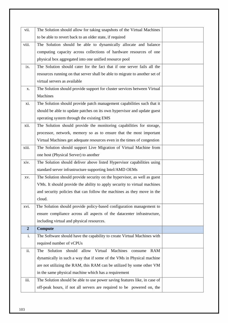
103
vii. The Solution should allow for taking snapshots of the Virtual Machines
to be able to revert back to an older state, if required
viii. The Solution should be able to dynamically allocate and balance
computing capacity across collections of hardware resources of one
physical box aggregated into one unified resource pool
ix. The Solution should cater for the fact that if one server fails all the
resources running on that server shall be able to migrate to another set of
virtual servers as available
x. The Solution should provide support for cluster services between Virtual
Machines
xi. The Solution should provide patch management capabilities such that it
should be able to update patches on its own hypervisor and update guest
operating system through the existing EMS
xii. The Solution should provide the monitoring capabilities for storage,
processor, network, memory so as to ensure that the most important
Virtual Machines get adequate resources even in the times of congestion
xiii. The Solution should support Live Migration of Virtual Machine from
one host (Physical Server) to another
xiv. The Solution should deliver above listed Hypervisor capabilities using
standard server infrastructure supporting Intel/AMD OEMs
xv. The Solution should provide security on the hypervisor, as well as guest
VMs. It should provide the ability to apply security to virtual machines
and security policies that can follow the machines as they move in the
cloud.
xvi. Th The Solution should provide policy-based configuration management to
ensure compliance across all aspects of the datacenter infrastructure,
including virtual and physical resources.
2 Compute
i. The Software should have the capability to create Virtual Machines with
required number of vCPUs
ii. The Solution should allow Virtual Machines consume RAM
dynamically in such a way that if some of the VMs in Physical machine
are not utilizing the RAM, this RAM can be utilized by some other VM
in the same physical machine which has a requirement
iii. The Solution should be able to use power saving features like, in case of
off-peak hours, if not all servers are required to be powered on, the
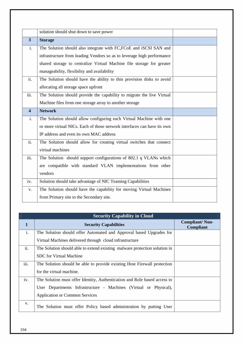
104
solution should shut down to save power
3 Storage
i. The Solution should also integrate with FC,FCoE and iSCSI SAN and
infrastructure from leading Vendors so as to leverage high performance
shared storage to centralize Virtual Machine file storage for greater
manageability, flexibility and availability
ii. The Solution should have the ability to thin provision disks to avoid
allocating all storage space upfront
iii. The Solution should provide the capability to migrate the live Virtual
Machine files from one storage array to another storage
4 Network
i. The Solution should allow configuring each Virtual Machine with one
or more virtual NICs. Each of those network interfaces can have its own
IP address and even its own MAC address
ii. The Solution should allow for creating virtual switches that connect
virtual machines
iii. The Solution should support configurations of 802.1 q VLANs which
are compatible with standard VLAN implementations from other
vendors
iv. Solution should take advantage of NIC Teaming Capabilities
v. The Solution should have the capability for moving Virtual Machines
from Primary site to the Secondary site.
Security Capability in Cloud
1 Security Capabilities Compliant/ Non-
Compliant
i. The Solution should offer Automated and Approval based Upgrades for
Virtual Machines delivered through cloud infrastructure
ii. The Solution should able to extend existing malware protection solution in
SDC for Virtual Machine
iii. The Solution should be able to provide existing Host Firewall protection
for the virtual machine.
iv. The Solution must offer Identity, Authentication and Role based access to
User Departments Infrastructure - Machines (Virtual or Physical),
Application or Common Services
v. The Solution must offer Policy based administration by putting User
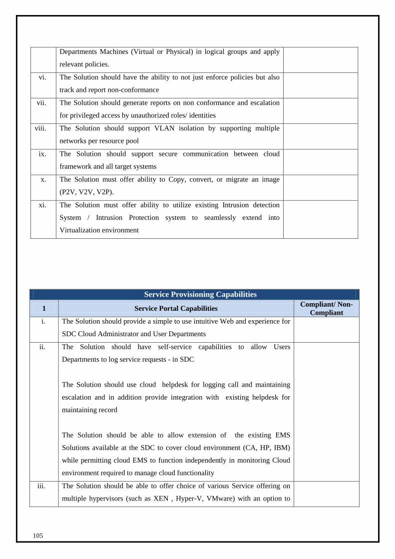
105
Departments Machines (Virtual or Physical) in logical groups and apply
relevant policies.
vi. The Solution should have the ability to not just enforce policies but also
track and report non-conformance
vii. The Solution should generate reports on non conformance and escalation
for privileged access by unauthorized roles/ identities
viii. The Solution should support VLAN isolation by supporting multiple
networks per resource pool
ix. The Solution should support secure communication between cloud
framework and all target systems
x. The Solution must offer ability to Copy, convert, or migrate an image
(P2V, V2V, V2P).
xi. The Solution must offer ability to utilize existing Intrusion detection
System / Intrusion Protection system to seamlessly extend into
Virtualization environment
Service Provisioning Capabilities
1 Service Portal Capabilities Compliant/ Non-
Compliant
i. The Solution should provide a simple to use intuitive Web and experience for
SDC Cloud Administrator and User Departments
ii. The Solution should have self-service capabilities to allow Users
Departments to log service requests - in SDC
The Solution should use cloud helpdesk for logging call and maintaining
escalation and in addition provide integration with existing helpdesk for
maintaining record
The Solution should be able to allow extension of the existing EMS
Solutions available at the SDC to cover cloud environment (CA, HP, IBM)
while permitting cloud EMS to function independently in monitoring Cloud
environment required to manage cloud functionality
iii. The Solution should be able to offer choice of various Service offering on
multiple hypervisors (such as XEN , Hyper-V, VMware) with an option to

106
select multi operating systems such as Windows 2003, 2008, RHEL / SUSE
Linux, etc., VLAN , Storage and quickly compute associated price for the
same as well as shows the deduction for overall Tenant approved
infrastructure Quota
iv. The Solution should offer Service catalog listing availability of Cloud
infrastructure like Virtual Machines, Physical Machines, Applications ,
Common Services offered by State Private cloud
v. The Solution should provide comprehensive service catalog with capabilities
for service design and lifecycle management, a web-based self-service portal
for users to order and manage services
vi. The solution should provide an on-boarding mechanism for the new tenants (
Department) on the cloud infrastructure that automatically creates the tenant,
the tenant administrators, allocates specific resources for the tenant like
storage pools, server pools, S/W packages, network pools (including VLANs,
DNS, IP address spaces, etc...)
vii. The Solution should offer Registration, Signup , Forgot Password and other
standard pages (Profile, Billing or Contact information)
viii. The Solution should enforce password policies and allow to personalize the
look & feel and logo on the user-interface panels
ix. The Solution should be able to offer choice of various hardware profiles,
custom hardware profile, Selection of operating systems, VLAN, Storage
x. The Solution should automate provisioning of new and changes to existing
infrastructure (Virtual, Physical, Application or Common Services) with
approvals
xi. The Solution should allow creation of library hosting various Operating
System, Databases and middleware that can be selected while creating new
virtual servers
xii. The Solution should track ownership and utilization of virtual machines,
Physical machines, and common services
xiii. The Solution must provide the capability to support the following Service
Request Types or reasons for contact:
Provisioning of Commuting Infrastructure - Virtual, Physical or
Applications
Repair (New, Cancellation, Change, Status Update) for the above
infrastructure
Enquiry (New, Cancellation, Change, Status Update)
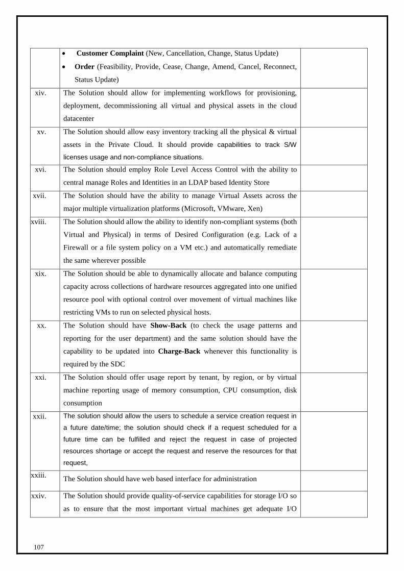
107
Customer Complaint (New, Cancellation, Change, Status Update)
Order (Feasibility, Provide, Cease, Change, Amend, Cancel, Reconnect,
Status Update)
xiv. The Solution should allow for implementing workflows for provisioning,
deployment, decommissioning all virtual and physical assets in the cloud
datacenter
xv. The Solution should allow easy inventory tracking all the physical & virtual
assets in the Private Cloud. It should provide capabilities to track S/W
licenses usage and non-compliance situations.
xvi. The Solution should employ Role Level Access Control with the ability to
central manage Roles and Identities in an LDAP based Identity Store
xvii. The Solution should have the ability to manage Virtual Assets across the
major multiple virtualization platforms (Microsoft, VMware, Xen)
xviii. The Solution should allow the ability to identify non-compliant systems (both
Virtual and Physical) in terms of Desired Configuration (e.g. Lack of a
Firewall or a file system policy on a VM etc.) and automatically remediate
the same wherever possible
xix. The Solution should be able to dynamically allocate and balance computing
capacity across collections of hardware resources aggregated into one unified
resource pool with optional control over movement of virtual machines like
restricting VMs to run on selected physical hosts.
xx. The Solution should have Show-Back (to check the usage patterns and
reporting for the user department) and the same solution should have the
capability to be updated into Charge-Back whenever this functionality is
required by the SDC
xxi. The Solution should offer usage report by tenant, by region, or by virtual
machine reporting usage of memory consumption, CPU consumption, disk
consumption
xxii. The solution should allow the users to schedule a service creation request in
a future date/time; the solution should check if a request scheduled for a
future time can be fulfilled and reject the request in case of projected
resources shortage or accept the request and reserve the resources for that
request,
xxiii. The Solution should have web based interface for administration
xxiv. The Solution should provide quality-of-service capabilities for storage I/O so
as to ensure that the most important virtual machines get adequate I/O
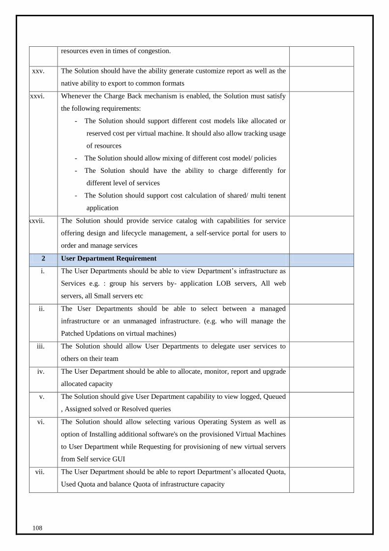
108
resources even in times of congestion.
xxv. The Solution should have the ability generate customize report as well as the
native ability to export to common formats
xxvi. Whenever the Charge Back mechanism is enabled, the Solution must satisfy
the following requirements:
- The Solution should support different cost models like allocated or
reserved cost per virtual machine. It should also allow tracking usage
of resources
- The Solution should allow mixing of different cost model/ policies
- The Solution should have the ability to charge differently for
different level of services
- The Solution should support cost calculation of shared/ multi tenent
application
xxvii. The Solution should provide service catalog with capabilities for service
offering design and lifecycle management, a self-service portal for users to
order and manage services
2 User Department Requirement
i. The User Departments should be able to view Department’s infrastructure as
Services e.g. : group his servers by- application LOB servers, All web
servers, all Small servers etc
ii. The User Departments should be able to select between a managed
infrastructure or an unmanaged infrastructure. (e.g. who will manage the
Patched Updations on virtual machines)
iii. The Solution should allow User Departments to delegate user services to
others on their team
iv. The User Department should be able to allocate, monitor, report and upgrade
allocated capacity
v. The Solution should give User Department capability to view logged, Queued
, Assigned solved or Resolved queries
vi. The Solution should allow selecting various Operating System as well as
option of Installing additional software's on the provisioned Virtual Machines
to User Department while Requesting for provisioning of new virtual servers
from Self service GUI
vii. The User Department should be able to report Department’s allocated Quota,
Used Quota and balance Quota of infrastructure capacity

109
viii. The User Department should be able to generate consumption reports for
Department’s cloud infrastructure (Virtual, Physical, Application or Common
Services)
3 SDC Private Cloud Administrator Requirement
i. Administrators should be able to automatically scale and/or manage resources
unilaterally (as also termed in the NIST definition) for tenant services without
manual intervention as and when required by the SLA requirements of the
service
ii. The Cloud Automation framework should provide capability for Roll based
Access for performing specific tasks
iii. Private Cloud Administrators should be able to easily configure, deploy, and
manage services through a highly intuitive service-centric interface, while
using a library of standard templates
iv. Private Cloud Administrators should be easily be able to take resources
offline and online
v. Private Cloud Administrators/Application Owners should be able to create,
manage, services using a web-based interface that presents a customized view
of resources based on your role in the organization
4 Capacity Management
i. The Solution should be able to determine how many more virtual machines
can fit the environment
ii. The Solution should identify idle, underutilized capacity to provide inputs to
the capacity management function such that informed decisions can be taken
iii. The Solution should support to identify and determine optimum sizing and
placement of virtual machines
iv. The Solution should provide forecast reports demonstrating forecasted
utilization
v. The Solution should support all of the following modeling scenarios: Physical
to Virtual, Virtual to Virtual, Virtual to Physical, Virtual to SDC private
Cloud, and Test to Production
vi. The Solution should provide a mechanism to automatically assess high
volumes of workloads and determines optimal placement on virtual machines
across the enterprise’s shared resource pools
vii.
The Solution should be able to utilize existing investment in tools/
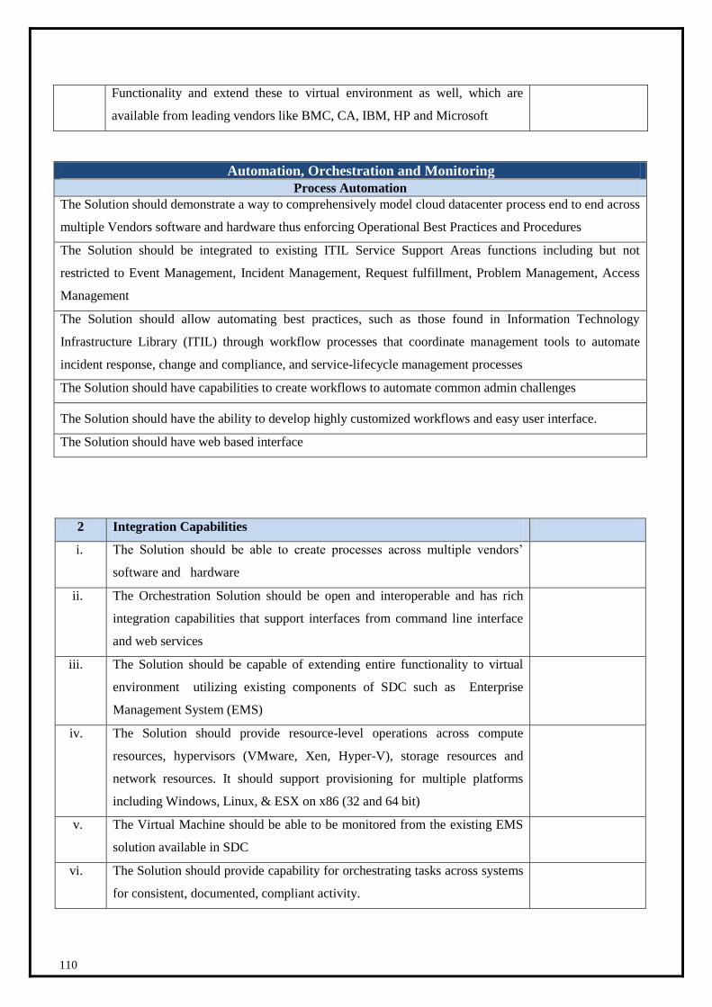
110
Functionality and extend these to virtual environment as well, which are
available from leading vendors like BMC, CA, IBM, HP and Microsoft
Automation, Orchestration and Monitoring
Process Automation
The Solution should demonstrate a way to comprehensively model cloud datacenter process end to end across
multiple Vendors software and hardware thus enforcing Operational Best Practices and Procedures
The Solution should be integrated to existing ITIL Service Support Areas functions including but not
restricted to Event Management, Incident Management, Request fulfillment, Problem Management, Access
Management
The Solution should allow automating best practices, such as those found in Information Technology
Infrastructure Library (ITIL) through workflow processes that coordinate management tools to automate
incident response, change and compliance, and service-lifecycle management processes
The Solution should have capabilities to create workflows to automate common admin challenges
The Solution should have the ability to develop highly customized workflows and easy user interface.
The Solution should have web based interface
2 Integration Capabilities
i. The Solution should be able to create processes across multiple vendors’
software and hardware
ii. The Orchestration Solution should be open and interoperable and has rich
integration capabilities that support interfaces from command line interface
and web services
iii. The Solution should be capable of extending entire functionality to virtual
environment utilizing existing components of SDC such as Enterprise
Management System (EMS)
iv. The Solution should provide resource-level operations across compute
resources, hypervisors (VMware, Xen, Hyper-V), storage resources and
network resources. It should support provisioning for multiple platforms
including Windows, Linux, & ESX on x86 (32 and 64 bit)
v. The Virtual Machine should be able to be monitored from the existing EMS
solution available in SDC
vi. The Solution should provide capability for orchestrating tasks across systems
for consistent, documented, compliant activity.
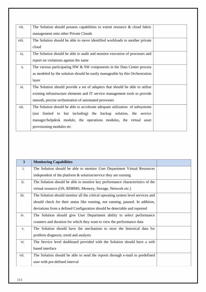
111
vii. The Solution should possess capabilities to extent resource & cloud fabric
management onto other Private Clouds
viii. The Solution should be able to move identified workloads to another private
cloud
ix. The Solution should be able to audit and monitor execution of processes and
report on violations against the same
x. The various participating HW & SW components in the Data Center process
as modeled by the solution should be easily manageable by this Orchestration
layer
xi. The Solution should provide a set of adapters that should be able to utilize
existing infrastructure elements and IT service management tools to provide
smooth, precise orchestration of automated processes
xii. The Solution should be able to accelerate adequate utilization of subsystems
(not limited to but including) the backup solution, the service
manager/helpdesk module, the operations modules, the virtual asset
provisioning modules etc
3 Monitoring Capabilities
i. The Solution should be able to monitor User Department Virtual Resources
independent of the platform & solution/service they are running
ii. The Solution should be able to monitor key performance characteristics of the
virtual resource (OS, RDBMS, Memory, Storage, Network etc.)
iii. The Solution should monitor all the critical operating system level services and
should check for their status like running, not running, paused. In addition,
deviations from a defined Configuration should be detectable and reported
iv. The Solution should give User Department ability to select performance
counters and duration for which they want to view the performance data
v. The Solution should have the mechanism to store the historical data for
problem diagnosis, trend and analysis
vi. The Service level dashboard provided with the Solution should have a web
based interface
vii. The Solution should be able to send the reports through e-mail to predefined
user with pre-defined interval

112
1.2.7 Security Components
Functional Requirement for Data Loss Prevention S
No
Compliance
1 The solution shall be able to discover, classify, monitor and protect data.
2 Overall the solution shall provide a central point of control and management for all its
components. The discovery and classification shall be based on various
identification mechanisms including regular expressions, keywords and phrases,
dictionaries, re-usable entities using programmatic validation logic to detect patterns,
full and partial fingerprinting, and proximity analysis using weightage as well
counting of detected parameters.
3 Should provide a single DLP solution management and policy creation interface for
DLP components –endpoints. The product shall come with pre-defined policies
which should be editable and also could be used to create new ones.
4 The solution shall have a dashboard showing details of the current activity within the
organization from the DLP point of view. The DLP system should be able to provide
detailed view of each of the components in the DLP systems like the agent scanning
status, detection point status, incident status etc. The dashboard should be
completely customizable and the solution should also able to provide a different
dashboard for each user with login privileges, as per his / her preferences or roles.
5 The solution shall have extensive reporting and auditing capabilities. The solution
should also provide out of box options to integrate with external Security and
Incident Management system as well as provide customized reports and
notifications.
6 The solution shall provide incident notification as well as escalation workflows for
unattended incidents.
9 The solution should be able to highlight the violated content within the incident for
clear identification and resolution of the incident.
10 The solution should be able to provide identity information on the sender (such as
full name, manager name, business unit). This should be accomplished across all
incidents email, non-email, storage as well as endpoint.
11 Different actions should be configurable based on the user context and risk level
associated with a particular data match - the risk levels too should be configurable
based on the risk score calculated.
Functional Requirement for Security Incident Management
viii. The Solution should be able provide integration with the existing helpdesk
system for incidents in SDC
ix. The Solution should trigger automated actions based on incoming events /
alerts
x. The Solution should provide a Knowledge base to store history of useful
incident resolution
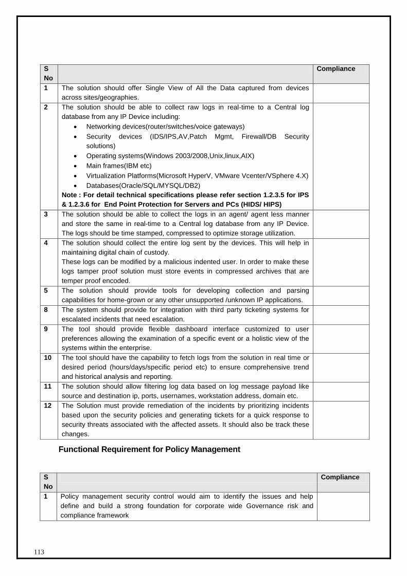
113
Functional Requirement for Policy Management
S
No
Compliance
1 Policy management security control would aim to identify the issues and help
define and build a strong foundation for corporate wide Governance risk and
compliance framework
S
No
Compliance
1 The solution should offer Single View of All the Data captured from devices
across sites/geographies.
2 The solution should be able to collect raw logs in real-time to a Central log
database from any IP Device including:
Networking devices(router/switches/voice gateways)
Security devices (IDS/IPS,AV,Patch Mgmt, Firewall/DB Security
solutions)
Operating systems(Windows 2003/2008,Unix,linux,AIX)
Main frames(IBM etc)
Virtualization Platforms(Microsoft HyperV, VMware Vcenter/VSphere 4.X)
Databases(Oracle/SQL/MYSQL/DB2)
Note : For detail technical specifications please refer section 1.2.3.5 for IPS
& 1.2.3.6 for End Point Protection for Servers and PCs (HIDS/ HIPS)
3 The solution should be able to collect the logs in an agent/ agent less manner
and store the same in real-time to a Central log database from any IP Device.
The logs should be time stamped, compressed to optimize storage utilization.
4 The solution should collect the entire log sent by the devices. This will help in
maintaining digital chain of custody.
These logs can be modified by a malicious indented user. In order to make these
logs tamper proof solution must store events in compressed archives that are
temper proof encoded.
5 The solution should provide tools for developing collection and parsing
capabilities for home-grown or any other unsupported /unknown IP applications.
8 The system should provide for integration with third party ticketing systems for
escalated incidents that need escalation.
9 The tool should provide flexible dashboard interface customized to user
preferences allowing the examination of a specific event or a holistic view of the
systems within the enterprise.
10 The tool should have the capability to fetch logs from the solution in real time or
desired period (hours/days/specific period etc) to ensure comprehensive trend
and historical analysis and reporting.
11 The solution should allow filtering log data based on log message payload like
source and destination ip, ports, usernames, workstation address, domain etc.
12 The Solution must provide remediation of the incidents by prioritizing incidents
based upon the security policies and generating tickets for a quick response to
security threats associated with the affected assets. It should also be track these
changes.
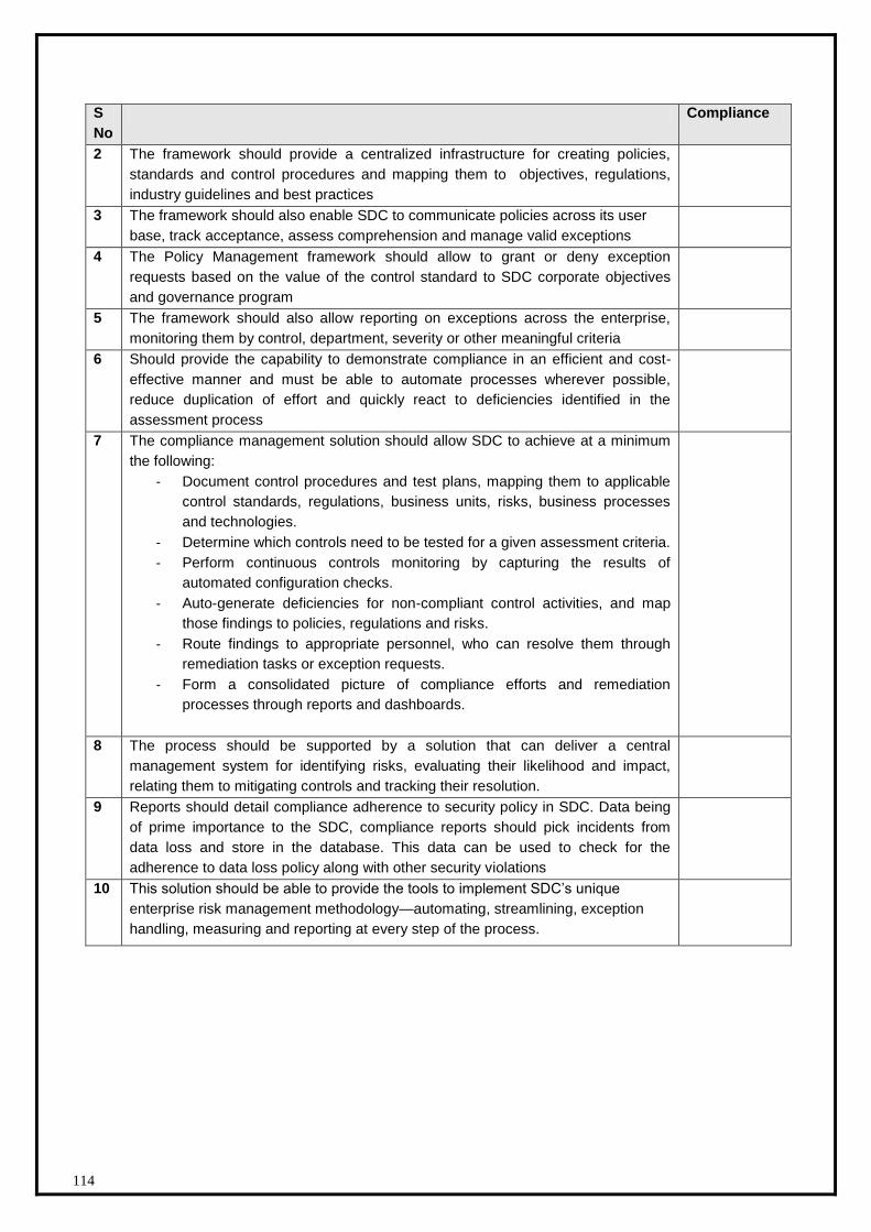
114
S
No
Compliance
2 The framework should provide a centralized infrastructure for creating policies,
standards and control procedures and mapping them to objectives, regulations,
industry guidelines and best practices
3 The framework should also enable SDC to communicate policies across its user
base, track acceptance, assess comprehension and manage valid exceptions
4 The Policy Management framework should allow to grant or deny exception
requests based on the value of the control standard to SDC corporate objectives
and governance program
5 The framework should also allow reporting on exceptions across the enterprise,
monitoring them by control, department, severity or other meaningful criteria
6 Should provide the capability to demonstrate compliance in an efficient and cost-
effective manner and must be able to automate processes wherever possible,
reduce duplication of effort and quickly react to deficiencies identified in the
assessment process
7 The compliance management solution should allow SDC to achieve at a minimum
the following:
- Document control procedures and test plans, mapping them to applicable
control standards, regulations, business units, risks, business processes
and technologies.
- Determine which controls need to be tested for a given assessment criteria.
- Perform continuous controls monitoring by capturing the results of
automated configuration checks.
- Auto-generate deficiencies for non-compliant control activities, and map
those findings to policies, regulations and risks.
- Route findings to appropriate personnel, who can resolve them through
remediation tasks or exception requests.
- Form a consolidated picture of compliance efforts and remediation
processes through reports and dashboards.
8 The process should be supported by a solution that can deliver a central
management system for identifying risks, evaluating their likelihood and impact,
relating them to mitigating controls and tracking their resolution.
9 Reports should detail compliance adherence to security policy in SDC. Data being
of prime importance to the SDC, compliance reports should pick incidents from
data loss and store in the database. This data can be used to check for the
adherence to data loss policy along with other security violations
10 This solution should be able to provide the tools to implement SDC’s unique
enterprise risk management methodology—automating, streamlining, exception
handling, measuring and reporting at every step of the process.
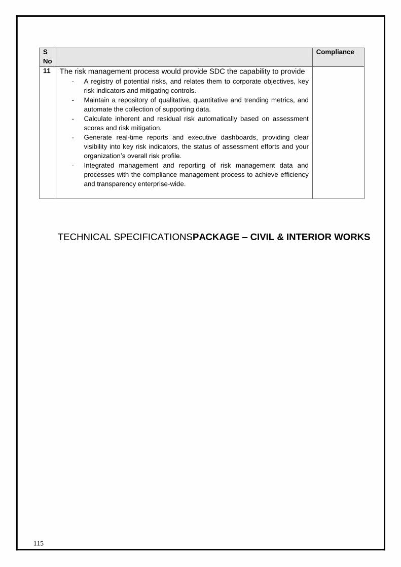
115
S
No
Compliance
11 The risk management process would provide SDC the capability to provide
- A registry of potential risks, and relates them to corporate objectives, key
risk indicators and mitigating controls.
- Maintain a repository of qualitative, quantitative and trending metrics, and
automate the collection of supporting data.
- Calculate inherent and residual risk automatically based on assessment
scores and risk mitigation.
- Generate real-time reports and executive dashboards, providing clear
visibility into key risk indicators, the status of assessment efforts and your
organization’s overall risk profile.
- Integrated management and reporting of risk management data and
processes with the compliance management process to achieve efficiency
and transparency enterprise-wide.
TECHNICAL SPECIFICATIONSPACKAGE – CIVIL & INTERIOR WORKS

SDC RFP Punjab - Volume II
116
1.3 SDC Architecture – Physical Infrastructure
1.3.1.1 Layout of Data Centre
Entire SDC area is logically divided in Zones based on MIT guidelines. Each of these zones are having
different objective described further in this section. The respective area of each Zone would
actually vary, primarily on the basis of number of applications and Size of the State. Total SDC area
for the Data Centre of Punjab is nearly 4000 sqr ft. The site is proposed to be in Mohali. SDC is
proposed to be on first floor of the building.
Zone A - This DC Server room area would host servers, server racks, storage racks and Networking
component. The area required for Zone A should approximately be 1500 sqr ft, This has to include the
staging area.
Zone B - Comprises of NOC room (16’.0’’X15’.9’’), reception area, Help Desk area, BMS Area
(11’.0’’X11’.0’’), Testing /Monitoring room, staging and reception, DC manager area, DC operation and
media storage room.. This zone requires approximately 1500 sq. ft
Zone C - Comprises of room for power panels, UPS and other power equipments (900 sqft). This zone
requires approximately 1000 sq. ft.
A revised Layout plan have been included in the RFP indicating individual sizes as sent to DIT earliar
along woth RFP assessment framework.

SDC RFP Punjab - Volume II
117
1.3.1.2 Technical Specifications – Civil and Interior Work
i. Demolition Work – Since this is a new building, demolition work is not required In case
some amount of demolition is required then DCO should take enough care not to make heavy
noises that disturbs other area in the building. Any damage done to the structure or other area
to be borne by the DCO. The DCO has to get permission from SIA before start of dismantling.
Cutting of reinforcement in any element for the building shall not be carried out without prior
permission of the SIA. The debris accumulated due to dismantling has to be disposed in an
area that is far from the area as directed by the SIA. There will no accumulation of debris in
the SDC vicinity for more than 12 hours.
ii. PEST CONTROL
Pest control treatment for the facility has to be done in accordance to the guideline laid as per
IS 633 part II.
iii. TRENCH WORKS
Trenches may be required for cables to run from the DG area to the SDC electrical room. The
bed of the trench shall be even throughout. The trench has to be filled by lime concrete or
sand as directed by SIA. Trench wall to made on hard bricks. There has to be service pits on
the length of the trench properly covered. These covers are to be openable and have
sufficient strength so that it does not gets damaged. Care to be taken for not making any
damage to the existing pipes, drains, cables. Any damage done has to be borne by the DCO.
iv. MASONARY WORKS
Brick Work:
a. All brick work should be carried out as per approved drawings mutually agreed between
the consultants, SIA and DCO. The brick work shall be done as per the norms laid down
by CPWD. The bricks (table molded) shall confirm to IS 1077. Other country bricks shall
be approved by the SIA. Proper curing has to be done for all the crick walls. Brick work is
not envisaged inside the DC area. However it may be required for the DG area. The DCO
has to create a DG shed so as to protect the DG from sunr and rain. The DG platform to
be raised over the ground so that water does not enter the DG. The fuel tank has to
mounted in similar fashion.

SDC RFP Punjab - Volume II
118
v. Plastering
The requirement of plaster work if required shall be to provided absolutely water tight
enclosure, dense, smooth and hard and devoid of any cracks on the interior or exterior.
Masonry and concrete surfaces, which call for applications of plaster, shall be clean, damp
and sufficiently rough and keyed to ensure proper bond, subject to the approval of the SIA.
vi. Water Proofing
Water proofing wherever required has to be done by the DCO as per the direction of SIA and
in accordance to the existing IS standard or as per CPWD norms.
vii. Laying of Vitrified Tile Flooring:
The vitrified tiles shall be selected by SIA and DCO mutually. Necessary edge, hole cutting
and chamfering and miter joints shall be done wherever required. The finished material shall
be protected against wear and tear and other works using heavy duty PVC sheets and 40mm
thick Plaster of Paris. This shall be cleared with acid as soon as the place is ready for
occupation. This shall be removed as soon as the related interior works are over.
viii. Granite wall cladding :
Granite wall cladding using 19mm thick pre polished slab as per the SIAs specs fixed to the
wall surface by means of 1:3 cement mortar used as a bonding agent, necessary clamps,
screws and cement grout. The vertical and horizontal joints between each panel of granite
should have groove (as per SIAs details).Necessary edge and hole cutting, chamfering and
granite joints shall be filled with cement paste mixed with pigment to match the colour of the
granite. The finished granite surface shall be protected against wear and tear by cladding it
with PVC sheet and gum tape. The final surface shall be granite polish by machine. The
pricing shall include hacking the existing wall or other places. All edge chamfers / cutting of
granite shall be mirror polished and no extra shall be paid for the same.

SDC RFP Punjab - Volume II
119
ix. Hardware And Metals
The hardware throughout shall bwiproe of superior quality. The DCO may be required to
produce and provide samples from many different sources before the Consultant/SIA. Fitting
generally shall be brass oxidized, unless otherwise specified and shall be suitable for their
intended purpose. In any case, it will have to be approved by the SIA before the DCO
procures it at the site of work.
Screws are to match the finish of the article to be fixed, and to be round or flat headed or
counter sunk as required. The DCO should cover up and protect the metal surfaces such as
brass, bronze, SS etc. with a thick grease or other suitable protective material, renew as
necessary and subsequently clean off and clear away on completion.
Aluminum and stainless steel shall be of approved manufacture and suitable for its particular
application. Generally the surface of aluminum shall have an anodized finish and both shall
comply with the samples approved by the SIA. All steel, brass, bronze, aluminum and
stainless steel articles shall be subjected to a reasonable test for strength, if so required by the
SIA at the DCO’s expense.
x. Glazier
All glass to be complying with IS 1548-1966. The compound for glazing to metal is to be a
special non-hardening compound manufactured for the purpose and of a brand and quality
approved by the SIA. All fore rated glass will be clear glass and with or without wire mesh. Fire
rating of glass to be 60 minutes.
xi. Paint
Providing and applying fire retardant paint of approved make and shade to give an even
shade over a primer coat as per manufacturers’ recommendations after applying painting
putty to level and plumb and finishing with 2 coats of fire retardant paint. Base coating shall
be as per manufacturer’s recommendation for coverage of paint.
For all vertical Plain surface.
For fireline gyp-board ceiling.
Providing and laying POP punning over cement plaster in perfect line and level with
thickness of 10 - 12 mm including making good chases, grooves, edge banding,
scaffolding pockets etc.
Applying approved fire retardant coating on all vertical surfaces, furniture etc. as per
manufacturer's specification.

SDC RFP Punjab - Volume II
120
xii. Upholstery
This may be required for the reception are of the SDC.This will be of first class standard
workmanship with webbing, no sag springs, coiled springs, padding and filling as specified on
drawing. Covering fabrics will be soon tufted and corded as approved by the SIA.
xiii. Plywood/ MDF Boards
Plywood/ medium density fiberboard/ blackboard/ teak particleboard/ veneered board, etc. As
specified in the approved list of manufacturers shall only be used. Only B.W.P grade phenol
formaldehyde bonded hot pressed plywood generally confirming to I.S.I 303 of approved
make shall only to be used. Marine plywood shall generally confirm to I.S. 710-1980.
Blockboard shall be equal or superior quality as per B.S. 3444
xiv. Laminates
Laminates where specified shall be of approved brand, type, texture and thickness and
manufactured as per IS: 2046 –1969. Fixing of laminates shall be done as per best trade
practices and strictly as per printed instructions of the manufacturers using Phenol
Formaldehyde Synthetic Resin Adhesive of approved make.
xv. False Flooring
The datacenter should have raise flooring on the area where IT equipment such as Server
racks, storage network racks are placed. The height of the raise floor to be 450 mm from the
real floor. The following specifications for the raise flooring may be adhered. Vendor to Quote
for product that is either meet the following specs or higher.
A: Mandatory Structural Parameters
Concentrated Loads :
540 Kgs ( 1200 lbf ) with a top-surface deflection under load and a permanent set not to
exceed , respectively, 2.54 & 0.25 mm ( 0.10 & 0.010 inch )
Ultimate Concentrated Load:
1350 Kgs (3000 lbf )
Rolling Loads :
270 kgs ( 600 lbf ) of the following magnitude, with a combination of local and overall
deformation not to exceed 1.02 mm (0.040 inch)
Stringer Load Testing :
204 Kgs (450 lbf) at the centre of the span with a permanent set not to exceed 0.25mm (
0.010 inch)
Pedestal Axial Load Test :
22 Kn axial Load per pedestal
SDC RFP Punjab - Volume II
121
B : Other Optional Structural Parameters :
Floor Panel Impact – Load Performance :
100 lbf when dropped from 36 inches ( 914 mm) on to 1-Sq.Inch ( 6.5 sq.cm) area located
anywhere on Panel without failing.
Uniformly Distributed Load (UDL):
1620 kg/m2 with a maximum permissible deflection of not more than 1.52 mm tested over an
area of 300x300 mm square for 100kgs load
C : Other Non structural Parameters :
Fire Rating :
The Panels shall confirm to Class O & Class 1 Fire Ratings tested as per BS 476 Part 6 (Fire
Propagation) & 7 (Surface spread of flame) as also ASTM E84 1998 (Flammability) and
ASTM E136 (Combustibility)
Electrical Resistivity :
As per ASTM F150/ NFPA 99 / ANSI S7.1 but modified for surface to ground to place one
electrode on the floor surface and to attach the other electrode on the pedestal.
xvi. Modular ceiling Tile
Providing and fixing of Mineral Fiber Ceiling tiles in true horizontal level false ceiling grid.
Using hot dipped galvanized steel section, exposed surface chemically cleaned capping
prefinished in baked polyester powder paint, Main tee of size 15 x 35 x 0.33 mm at every 1200
mm C/C max and rotary stitched cross tee of size 15 x 30 x 0.33mm at every 600 mm C/C
0.457 mm wall angle around the wall to form a grid of 600 mm x 600 mm and suspending the
grid using 2 mm GI rod and 6 mm rawl plug at every 1200 mm intervals at the main tee and
laying the Ceiling tiles of size 595 mm x 595 mm x 15 mm over the formed grid having fire
rating of 60 minutes as per BS 476/23 of 1987, Noise reduction Coefficient (NRC) of 0.50-
0.60, to resist temperature and humidity conditions up to 40degree (104deg. F) and humidity
of 95% RH, Weight of 3.5Kgs/SQ.M.
xvii. Gypsum Ceiling
Suspended gypsum board false ceiling of G.I.Channel grid type framework, gypsum boards,
paper tape, gypsum putty and cutouts for light fittings, A/C grills, and Fire Alarm accessories
has to be provided by the DCO in the area wherever required as per mutually agreed and approved
drawing. The gypsum board panels 12 mm thick are secured on to bottom of the frame work by
means of screws. Necessary cutouts for lights, detectors and other ceiling mounted equipment needs
to be provided. The surface of the ceiling must be smooth. Plastic emulsion paint to be done on the
gypsum ceiling.
SDC RFP Punjab - Volume II
122
xviii. Record protection equipment – Fire proof cabinets Features:
Computer Grey, Polyurethane (PU) paint.
sizes -300 ltrs.
Protects from fire, dust, heat, moisture, magnetic fields, electrostatics and accidental
damage.
Designed to withstand temperatures up to 1000 degree C for over an hour.
Average Internal temperature below 30 degrees C after 60 minutes of testing in
furnace.
Average internal temperature below 44 degree C after a 6-hour soak out period.
Adjustable shelves and pull out trays shound be available
Locking system
Two 10- lever high security Cylindrical Locks.
Snap shut mechanism.
The safe has to be as per IS:14562 for 1 hr. Fire
endurance and 1 hr. Fire & Impact Test.
1.3.1.2.1 Modes of Measurement
1. Walls, Partitions,
main wall
Elevational Area (volumetric)
2. Flooring Plan area between skirting
3. Skirting Running length
4. Windows Elevational Area ( including frame)
5. False Ceiling Actual Area between partitions (Rate shall be inclusive of
making holes/ cutouts / openings for light fittings, AC grills,
Smoke Detectors, Sprinklers, provision of perimeter
channel for support/fixing of grills / light fittings and suitable
boards of 300 x 300 x 10mm for spotlights. No deductions
shall be made for any such cutouts/opening). However,
column areas shall be deductible.
6. Partition Elevational Area (From finished floor/false floor level to
finished false ceiling level).
7. Wall Paneling Elevational Area
SDC RFP Punjab - Volume II
123
8. Workstations Nos.
9. Tables Nos.
10. Rear/Side Credenzas Elevational Area
11. Utility/Staff counters Running length
12. High/Low Storages Elevational Area
13. Storage above
counter
Elevational Area
14. Door/Frames Nos.
15. Rolling
Shutters/Collapsible
gate
Elevational Area
16. Shutters for ducts and below window cill
Elevational Area
17. Blinds Elevational Area 18. Grills Actual surface area 19. Pest Control / Anti-
termite treatment Carpet floor area, plan area
Note: Measurements shall be recorded upto three digits after decimal point Note:
All material to be used shall be of first quality unless otherwise specified. All sizes of materials mentioned shall be finished sizes. All materials used shall be of I.S.I grade wherever applicable.
Important conditions:
All types of shop/ coordinated/ elevation/ working/ Good for construction drawing has to be submitted to the SIA and without the approval of the SIA no work will be executed.
Data sheet/ Catalogues/ brochures of the material have to be submitted before use.
The vendor has to get the sample of each item approved from the SIA before using for construction
The sample required any test as per the direction of SIA the cost of sample and testing will be borne by the bidder. Test lab will be decided by SIA.
Quantity mentioned in the BOQ is approximate. Bidders need to visit the site and assess the quantities before quoting.
SDC RFP Punjab - Volume II
124
1.3.1.3 Technical Specifications – Electrical
1.3.1.3.1 UPS, Batteries and Accessories
Purpose
The purpose of this specification is to define the design, manufacture and testing
characteristics required in view of supplying, putting into operation and maintaining an
Uninterruptible Power Supply system (referred to as a UPS in the rest of this document). The
UPS system shall be designed to supply dependable electric power to:
The total load supplied by the UPS system shall be equal to 250kVA, at a load power factor pf
greater than 0.9.
Brief description
There will be 2 UPS system of 250KVA each in each BUS of the LT Panel. Each set of UPS in
a BUS will have separate battery banks for 30 minutes backup on each on full loadUPS units
(same power rating), operating in double-conversion mode (also called on-line mode); it shall
be a VFI-type UPS (as per standard IEC 62040-2).and shall comprise the following
components, described below in this specification:
6 pulse/12 Pulse/PWM rectifier with active/passive filter ( if required)
battery charger;
inverter;
battery;
static bypass (via a static switch) for each UPS unit; manual maintenance bypass for each UPS unit user and communications interface;
battery management system;
any and all other devices required for safe operation and maintenance, including circuit breakers, switches, etc.
The UPS system shall ensure continuity of electric power to the load within the specified
tolerances, without interruption upon failure or deterioration of the normal AC source (utility
power) for a maximum protection time determined by the capacity of the backup batteries
installed.
Operating principle

SDC RFP Punjab - Volume II
125
Each double-conversion UPS unit (also called on-line) shall operate as defined below.
i. Normal operation
The rectifier shall supply the corresponding inverter with DC current while the charger
simultaneously float charges its battery. The load is continuously supplied with dependable
electrical power by the inverter.
ii. Operation on battery power
Upon failure or excessive deterioration of the normal AC source, the inverter shall continue to
supply the load with power from its battery without interruption or disturbance, within the limits
imposed by the specified battery backup time.
iii. Battery recharge
When the normal AC source is restored, the rectifier shall again power the corresponding
inverter, without interruption or disturbance to the load, while the charger automatically
recharges the battery.
iv. Load sharing operation and redundancy
The units shall operate in load sharing mode with redundancy, with the load shared equally
between the units.
Redundancy shall be of the “n+n” type, i.e. “both the UPS will work independently but
synchronized for voltage, and frequency through load bus synchronization technology . In
case of failure of one UPS the load will be transferred to the other one without affecting or
creating any disturbance to the load.
v. Transfer to bypass AC source
In the event of an overload exceeding system capabilities (short-circuits, heavy inrush
currents, etc.) the load shall be automatically transferred, instantaneously and without
interruption, to the bypass AC source,on the condition that bypass power is available and
within tolerances.
To that end, synchronisation of each inverter in phase and frequency with the bypass source
shall be automatic. Transfer of the load back to the UPS-unit outputs shall be automatic or
manual. During transfer, the load shall not suffer an outage or disturbance in the supply of
power.
To ensure transfer in complete safety, the system shall close simultaneously the static
switches.
SDC RFP Punjab - Volume II
126
On request, the UPS system may automatically transfer the load with a micro-interruption if a
major fault occurs on the UPS system and if synchronisation with the bypass source has not
been established.
The above feature is required but may not be necessarily in force as it is not expected or
desirable to feed unconditioned power to the SDC through bypass line.
vi. Maintenance on UPS units
For maintenance purposes, all electronic components shall be accessible from the front of the
UPS. In addition, a built-in manually-operated mechanical bypass system shall be:
Installed in each UPS unit; Installed separately in an external bypass enclosure or cubicle
For personnel safety during servicing or testing, this system shall be designed to isolate the
UPS units while continuing to supply power to the load from the bypass AC source. Transfer
to the manual bypass mode and back shall be possible without interruption to the load.
The UPS shall also include a device making it possible to isolate the rectifiers and the
chargers from the normal AC source.
vii. Battery maintenance
For safe maintenance on the battery of each UPS unit, the system shall include a circuit
breaker to isolate the battery from the corresponding rectifier/charger and inverter.
When the battery is isolated from the system, the UPS shall continue to supply the load
without interruption or disturbance, except in the event of a normal AC source outage.
Sizing and general characteristics
i. Technology
The UPS shall be based on double conversion SCR/PWM rectifier and IGBT Inverter
technology with built-in thermal monitoring and a high free-frequency chopping mode to
dynamically optimise efficiency and power quality.
RatingThe UPS system shall be sized to continuously supply a load of 80 kVA (min), at a load power factor (pf) of 0.9. It shall be made up of 2 UPS units in each BUS, each with an identical rating of 80 KVA.
ii. Battery backup time
The backup time of each battery in the event of a normal AC source outage shall be 30
minutes per UPS (min 80KVA load with 0.9 load pf of resistive load)
The service life of each battery shall be equal to at least 15 years.
Batteries shall be selected and sized accordingly.
SDC RFP Punjab - Volume II
127
iii.Reliability and MTBF
The UPS has to be highly reliable with a high MTBF
iv. Types of loads accepted
If all the connected loads are non-linear (100% non-linear loads), each UPS unit shall accept
high crest factors (3:1) without derating of output.
For both linear and non-linear loads, the voltage total harmonic distortion at UPS output
(THDU downstream) shall respect the following limits:
THDU downstream ph/ph and ph/N 3% for linear loads;
THDU downstream ph/ph and ph/N 5% for non-linear loads.
v. Limitation of harmonics upstream of the UPS system
The UPS system shall not draw a level of harmonic currents that could disturb the upstream
AC system, i.e. it shall comply with the stipulations of guide IEC 61000-3-4 (formerly IEC 1000
3-4).
In particular, the UPS shall respect the following characteristics at the normal AC input: total
harmonic current distortion (THDI) upstream of the rectifier not exceeding:
1. 7% at full rated load for an computer grade load
2. input power factor (pf) greater than or equal to 0.92.
To achive the above use of different kinds of rectifier, active or passive filters are acceptable.
However the foot print of the UPS due to this should not vary by more than 15%.
These performance levels, due to the “clean” input rectifier drawing sinusoidal current, limit
upstream distortion and avoid oversizing of upstream equipment (cables, circuit breakers,
etc.), without requiring additional filters.
vi. Efficiency
Overall efficiency of each UPS unit shall be greater than or equal to:
92% at full rated load in normal mode;
90% at 50% rated load in normal mode;
85% at quarter rated load
vii. Noise level
The noise level, measured as per standard ISO 3746, shall for each unit be less than:
72 dBA.
SDC RFP Punjab - Volume II
128
AC sources
The UPS system shall be designed to receive power from the sources presented below.
i. Normal AC source (rectifier input)
The normal AC source supplying the UPS shall, under normal operating conditions, have the
following characteristics:
rated voltage: 415V +10%, -15% at all load conditions
number of phases: 3 ph + earth. The neutral may or may not be necessary.
frequency: 50 Hz ± 6%.
ii. Bypass AC source
(static-bypass input, if separate from rectifier input)
The bypass AC source shall continue to supply the load, without interruption, if its
characteristics remain within voltage tolerances
Outside these tolerances, it shall be possible to supply the load, but in downgraded mode.
Electrical characteristics
I. Rectifiers and chargers
i. Supply
The rectifier and charger module shall be supplied via the normal AC input. It must be
capable of operating without a neutral
ii. Inrush current
A device shall be provided to limit inrush currents.
iii. Battery-current limiting
For long battery life, an electronic device shall automatically limit the charging current to
the maximum value specified by the battery supplier
iv. Voltage regulation
Rectifier/charger regulation on each unit shall take into account the ambient temperature
of the battery and shall ensure DC output voltage fluctuations of less than 1% irrespective
of load and AC input voltage variations
II. Batteries
The UPS system batteries shall be 2 Volt, Sealed, lead acid, valve regulated, heavy duty
type having design float life of 15 years , sized considering end cell voltage of 1.75 Volts
per cell 30 Minutes discharge.
SDC RFP Punjab - Volume II
129
Bidder has to submit detailed battery backup calculation duly authenticated by battery
manufacturers.
III. Inverters
Each inverter shall be sized to supply a load rated
250 KVA at a load power factor (pf) of 0.9, taking into account the characteristics
presented below.
i. Output voltage
Rated voltage: 380 / 400 / 415 volts rms, adjustable via the user interface, within
tolerances of +/- 3%.
Number of phases: 3 phases + neutral + earth.
Steady-state conditions: The variation in the rated voltage shall be limited to ± 2% for
a balanced load between 0 and 100% of the rated power, irrespective of normal AC
input and DC voltage levels.
Voltage variations for load step changes: Output voltage transients shall not exceed
± 5% of rated voltage for 0 to 100% or 100 to 0% step loads. In all cases, the voltage
shall return to within steady-state tolerances in less than 50 milliseconds.
Unbalanced load conditions: For a 100% load unbalance, the voltage unbalance
shall be less than 2% in phase-to-neutral amplitude.
ii. Output frequency
Rated frequency: 50 Hz.
Variations :- ± 0.5 Hz,
iii. Synchronisation with bypass power
When bypass power is within tolerances
To enable transfer to bypass power, the inverter output voltage shall be synchronised
with the bypass source voltage whenever possible. To that end, during normal operation,
a synchronisation system shall automatically limit the phase deviation between the
voltages to 3 degrees, if the bypass frequency is sufficiently stable (within adjustable
tolerances of ± 0.5% to ± 8% with respect to the rated frequency).
Synchronisation with an external source
It shall be possible to synchronise with all types of external source.
For example, if the bypass source is a generator set, the synchronisation tolerances
shall be approximately ± 0.5% to ± 8% (adjustable) with respect to the rated frequency.
Autonomous operation following loss of synchronisation with bypass power
When the bypass source frequency deviates beyond these limits, the inverter shall
switch over to free-running mode with internal synchronisation, regulating its own

SDC RFP Punjab - Volume II
130
frequency to within ± 0,001Hz. When bypass power returns to within tolerances, the
inverter shall automatically resynchronise.
Variation in frequency per unit time
During the switch to free-running mode and the switch back to synchronised mode,
frequency variations per unit time (dF/dt) shall be limited to 1 Hz/s or 2 Hz/s (user
defined).
iv. Overload capacity
The UPS shall be capable of supplying for at least:
10 minute a load representing 125% of the rated load;
60 second a load representing 150% of the rated load.
IV. Static-bypass
I. Static bypass
Each UPS unit shall be equipped with a static bypass comprising a static switch. The
static bypasses shall be controlled simultaneously by a built-in system. Instantaneous
transfer of the load from the inverters to bypass power and back shall take place without
a break or disturbance in the supply of power to the load, on the condition that the
bypass source voltage and frequency are within the tolerances and that the inverters are
synchronised.
Transfer shall take place automatically in the event of a major overload or an internal
inverter fault.
Manually initiated transfer shall also be possible.
II. Static-switch protection
Each static switch shall be equipped with an RC filter for protection against switching
overvoltages and lightning strikes.
III. Discrimination and short-circuit capacity
If the bypass power is within the tolerances specified, the presence of the static switch
shall make it possible to use the short-circuit power of the bypass source to trip the
downstream protection devices of the common inverter output.
V. Mechanical characteristics
I. Mechanical structure

SDC RFP Punjab - Volume II
131
The UPS and batteries shall be installed in cabinet(s) with a degree of protection IP20
(standard IEC 60529). Access to the subassemblies making up the system shall be
exclusively through the front.
II. Dimensions
The UPS shall require as little floor space as possible. To gain space, it shall be possible
to install the UPS with the back to the wall. However, space in the back can be given
based on technical requirement. The ratio between the foor print and weight will be a
criterion for selelcting the product/ brand. It should be as low as possible.
III. Connection
To facilitate connections, all terminal blocks must be easily accessible from the front
when the UPS is installed with the back to the wall. Entry of upstream and downstream
power cables, as well as any auxiliary cables, shall be possible through the bottom for a
false floor.
The neutral conductor shall be oversized for any third-order harmonic currents and their
multiples (the size of the neutral shall be 1.5 times that of each phase).
SDC RFP Punjab - Volume II
132
IV. Safety
The equipment shall meet the requirements of degree of protection index IP21, in
compliance with standard IEC 60529.
For the safety of maintenance personnel, the cabinet shall be provided with a manually
operated mechanical bypass designed to isolate the rectifier, charger, inverter and static
switch while continuing to supply the load from the bypass AC source.
It shall be possible to send to the UPS an external EPO order resulting in opening of the
battery circuit breaker and the upstream circuit breaker.
VI. Environment conditions
I. UPS (not including batteries)
i. Operation
The UPS shall be capable of operating under the following environmental conditions
without loss of performance:
ambient temperature range: 0° C to +40° C;
recommended temperature range: +20° C to + 25° C;
maximum relative humidity: 95% at 25° C;
maximum altitude without derating: 1000 meters.
ii. Storage
The UPS, not including the battery, shall be designed for storage under the following
conditions:
ambient temperature range: -10° C to +45° C.
VII. Protection
I. UPS
Each UPS unit shall include protection against AC-source overvoltages (as per standard
IEC 60146), excessive external or internal temperature rise and vibrations and impacts
during transport.
SDC RFP Punjab - Volume II
133
II. Rectifier and charger
The rectifier and charger shall automatically shut down if the DC voltage reaches the
maximum value specified by the battery manufacturer or if the temperature exceeds the
limits specified above.
III. Inverter
Inverters shall self-protect against overloads and short-circuits, irrespective of the
operating mode (AC power or battery power). There has to be a inbuilt Isolation
transformer of full capacity at the output of inverter for galvanic isolation.
IV. Batteries
i. Protection against deep discharge and self-discharge
The UPS shall comprise a device designed to protect the battery against deep
discharges, taking into account the characteristics of the discharge cycles, with isolation
of the battery by a circuit breaker.
ii. Independent regulation and monitoring systems
A regulation system shall regulate the battery voltage and the charge current.
A second system, independent of the regulation, shall monitor the battery voltage and
the charge current. Consequently, if the regulation system fails, the monitoring system
steps in to shut down the charger and avoid overcharging.
iii. Regulation of the battery voltage depending on the ambient temperature
A temperature sensor adapts the charge voltage to the ambient temperature.
This regulation system takes into account the chemical reaction and prolongs the battery
service life.
The permissible temperature range is set in the personalisation parameters.
An alarm shall be issued for temperatures outside the permissible range.
iv. Self-test
Battery monitoring shall be carried out by an automatic device. Self-test intervals shall
be set to one month by default, but shall be adjustable.
This self-test system shall, where necessary, initiate indications via LEDs on the front
panel or a message to a remote monitoring system.
v. Possibility of battery circuit-breaker management
SDC RFP Punjab - Volume II
134
Each UPS unit shall be capable of receiving and managing two battery circuit breakers.
Battery availability is improved by dividing it into two sections. If one section is faulty, the
second shall remain available and provide approximately half of the backup time.
VIII. Battery Management
I. Battery meter
The battery-meter function estimates the available backup time of the UPS as a function
of the battery charge and the percent load.
II. Digital battery monitoring
The UPS shall be equipped with a system for battery digital management.
Based on a number of parameters (percent load, temperature, battery type and age), the
system shall control the battery charge voltage and continuously calculate:
The true available backup time
The remaining service life.
IX. User interface and communication
I. User interface
UPS operation shall be facilitated by a user interface, on each UPS unit, comprising:
a graphic display;
controls;
status indications with mimic panel.
The information and controls shall be centralised by a system (electronic board) built into
one of the UPS units.
II.Graphic display
The graphic display shall facilitate operation by offering the functions listed below.
Operating language: It shall be possible to display in the language all the operating information supplied on the screens.
Step by step operating help
The graphic display shall assist the user by providing step by step help in the user’s language.
Display of measurements
It shall be possible to display the following measurements:

SDC RFP Punjab - Volume II
135
o inverter output phase-to-phase voltages;
o inverter output currents;
o inverter output frequency;
o voltage across battery terminals;
o battery charge or discharge current;
o rectifier/charger input phase-to-phase voltages;
o rectifier/charger input currents;
o active and apparent power;
o power factor of the load;
Display of status conditions and events
It shall be possible to display the following indications:
o load on battery power;
o load on UPS;
o load on automatic bypass;
o general alarm;
o battery fault;
Remaining battery backup time;
o low battery warning;
o bypass AC source outside tolerances;
Display of operating graphs
It shall be possible to display on the screen curves and bargraphs over significant periods
for the measurements mentioned above.
Log of time-stamped events
This function shall store in memory and make available, for automatic or manually initiated
recall, time-stamped logs of all important status changes, faults and malfunctions,
complete with an analysis and display of troubleshooting procedures. It shall be possible
to time stamp and store at least 200 to 2000 events for each UPS unit.
III.Controls
The UPS shall comprise the following controls:
a. ON and OFF buttons
ON /OFF button shall control UPS-unit ON/OFF status.
It shall be possible to turn OFF the UPS externally via an isolated dry contact.
SDC RFP Punjab - Volume II
136
b. EPO terminal block
The UPS shall be equipped with an emergency power off terminal block for complete
system shutdown following reception of an external control signal. The EPO command
shall result in:
a. shutdown of UPS units;
b. opening of the static switch on the bypass line and of the battery circuit breaker;
c. Opening of an isolated dry contact on the programmable card.
c. Alarm reset button
This button shall turn off audio alarms (buzzer). If a new alarm is detected after clearing
the first, the buzzer sounds again.
d. Status indications with mimic panel
Indication of status conditions shall be distinct of the graphic display.
Three LEDs on the control panel indicate the following status conditions:
i. load protected;
ii. minor fault;
iii. major fault.
The mimic panel shall represent the UPS and indicate the status of the load supply using
five two-colour (red and green) LEDs:
load supplied (LED at UPS output on mimic panel),
inverter on (inverter LED on mimic panel),
operation on battery power (LED between battery and inverter on mimic
panel),
bypass activated (bypass LED on mimic panel),
PFC rectifier on (rectifier LED on mimic panel).
IV. Communication
i. Standard communication
It shall be possible to remote the following controls, indications and measurements. To
that end, each UPS unit shall have as standard equipment:
d. a programmable card for input/ output information.
This card shall provide a total of eight dry contacts, six for outgoing information
and two for incoming information.
SDC RFP Punjab - Volume II
137
e. at least three communication ports for later addition, without interrupting operation,
of communication cards implementing different protocols, e.g. SNMP, JBus/
ModBus, RS232.
ii. Communications options
The UPS system shall be designed to enable the extension of communications, without
system shutdown, to the following types of cards:
a. an SNMP communication card for connection to an Ethernet network, for
connection to a computer-network management system;
b. an RS485 serial-link communication card capable of implementing the JBus/
ModBus protocol for connection to a building management system (BMS);
c. an RS232 serial-link communication card for communication with a modem and a
remote-maintenance system;
d. an XML-Web communication card for direct UPS connection to an intranet
network, without connection to a server, capable of supplying information via a
standard web browser.
The UPS shall be detectable by supervision software for large UPS systems.
Shutdown and administration software shall be available in addition to the communication
cards.
V.Standards, tests and quality assurance
1. Standards
All equipment shall be designed and built in accordance with accepted engineering
practice and applicable international standards, in particular the standards listed below.
i. IEC 6014B-4: UPS - Performance.
ii. IEC 62040-1 and EN 62040-1: UPS - Safety.
iii. IEC 62040-2 level A: UPS - Electromagnetic compatibility [level C3 / C2 class A is
optional].
iv. IEC 62040-3 and EN 62040-3: UPS - Performance.
v. IEC 60950 / EN 60950: Safety of IT equipment, including electrical business
equipment.
vi. IEC 61000-2-2: Compatibility levels for low-frequency conducted disturbances and
signalling in public low-voltage power supply systems.
vii. IEC 61000-3-4: Limits for harmonic current emissions (equipment input current > 16
A/ph).
viii. IEC 61000-4: EMC - Electrical fast transient/burst immunity.

SDC RFP Punjab - Volume II
138
ix. EN 55011 and EN 55022: Limits and methods of measurement of radio interference
characteristics of industrial, scientific and medical (ISM) radio-frequency equipment -
Level A conducted and radiated emissions.
x. IEC 439: Low-voltage switchgear and controlgear assemblies.
xi. IEC 60529: Degrees of protection provided by enclosures (IP Code).
xii. ISO 3746: Sound power levels.
xiii. CE marking/ Equivalent as per Indian standard.
The equipment must comply with environmental-protection standards; with production
taking place on premises certified ISO 14001. The UPS design procedure shall be
covered by an ISO 9001 quality system as well as a dependability study to ensure
maximum reliability.
2. Certification of conformity
The manufacturer shall provide, on request, a complete qualification file demonstrating
compliance with the above standards.
VI.Services
1. Maintenance
The DCO shall propose contracts covering four levels of maintenance.
i. Level one: simple checks and settings, procedures accessible without any
dismounting and involving no risk.
ii. Level two: preventive maintenance, checks not inhibiting continuous operation of
the system and preparing operators for Manufacturer services.
iii. Level three: trouble-shooting. Repairs by standard exchange of subassemblies and
functional power and control components. Preventive-maintenance operations, both
systematic and when indicated by qualified diagnosis.
iv. Level four: major preventive and corrective maintenance operations or technical
upgrades during start-up, operation or renovation of the UPS installation and
recycling of equipment or components representing a risk. These operations require
the use of devices and means that have been calibrated by certified organisations.
2. Technical competency
i. Customer operators: the supplier shall offer a level 2 training program.
ii. Service personnel: the supplier shall ensure that service personnel are qualified for
level 4.
SDC RFP Punjab - Volume II
139
3. System start-up
The system and equipment shall be started up on site by the supplier or its authorised
agent. The procedure shall include checks on the characteristics of the upstream and
downstream protection devices and on the UPS installation parameters.
4. Replacement parts
The suppler shall undertake to provide certified original replacement parts for at least ten
years following the date of delivery.
5. Recycling and renovation/substitution
At the end of the UPS service life, the supplier shall guarantee the continuity of service of
the customer’s installations if necessary, including dismantling of equipment and
replacement of equipment, in compliance with applicable standards on environmental
protection.
VII.Warranty
The rectifier/ charger and inverter subassemblies shall be guaranteed (parts and labour on
site) for five year following the start-up date.
The sealed lead-acid battery shall be covered by the same warranty as the UPS.
VIII.Services
Required services include:
supply of the UPS and any accessory parts or elements;
carriage - paid UPS transportation and delivery to the site.
Options:
UPS handling and installation on the site;
connections between the battery and the UPS;
connection of the normal AC source to the rectifier/ charger;
connection of the bypass AC source to the input transformer or bypass input;
connection of the load circuits to the UPS output.
Static Transfer Switch: Static Switch (STS) should be planned for the IT equipments where there is no provision of redundant RPS, the equipments like L2 switches, Firewall, IPS etc may be considered. (The basic purpose of a static switch is that is takes the power from 2 sources and output it as one, it has an inbuilt automatic bypass switch which will enable any one source to be enabled and if one goes down the other input starts working which will give a uninterrupted power at the output. The specification is 16A STS switch.

SDC RFP Punjab - Volume II
140
1.3.1.4 Technical Specification – Diesel Generating Sets
Scope
Work covered by this contract shall conform to latest CPCB norms effective from July 1,
2004 include design, manufacture, supply, transportation, delivery, installation, testing and
commissioning of automatic start direct coupled Diesel Generator Sets suitable for
continuous round the clock operation at upto rated output with permissible overload along
with associated works. Items included (but not limited to) in the contract are abstracted as
below.
Diesel engines directly coupled with alternators mounted on a rigid fabricated steel
base frame with resilient antivibration mountings.
AMF cum Auto Synchronising cum load sharing panels. All DG sets should be
automatic, not manual. I.e. they should turn on and off automatically.
DG cooling system.Radiator cooled.
Exhaust piping with Silencer to provide 25 dBA insertion loss
Electric starting equipment including batteries and battery chargers.
Fuel supply system including Oil Storage and automatically operated Fuel
Transmission System. Real Time Flow meter based monitoring of diesel through
BMS should be there.
Acoustic treatment of DG set as per prevailing norms.
Statutory approvals including permission from Electric Supply Authority for
operation of DG sets, approval from EB power authority clearance from Electrical
Inspector, approval from Pollution Control Board.
Coordination with DG Auto Synchronisation, Auto Load Control & AMF Panel
Vendor. And there should be proper maintenance schedule to maintain the best
efficiency.
PROPOSED OPERATIONAL SCHEME
The premises power supply is from Transformer for lighting, power and HVAC loads. The
supply of transformer is not in the scope of bidder. The standby power also has 3 numbers
of 320 KVA ( +/-5%) DGSets for Entire loads which work in parallel fashion with auto
synchronising facility.
The Synchronising power bus has been split into three different sections by two bus
coupler. This has been done to ensure that, in case, the synchronising feature does not

SDC RFP Punjab - Volume II
141
work for any reason, the bus coupler can be switched off and the DG sets can be operated
individually. All DG sets shall start immediately on sensing loss of EB power after an
adjustable time gap from 0 to 10 seconds. This shall be controlled based on the time run
by each of the DG sets and shall be field settable. Provision shall also be made to
manually select the sequence of starting of the DG sets. Once all the DGs are in running
condition, the Intelligent micro controller will switch off the DGs one by one based on the
load condition. In case the load is less than 80% of 320 KVA ( +/-5%), DG-3 will switch off
first and then the DG-2. The DG-1 will be running and feed the load. At any point of time
the load increases beyond 80% of 320 KVA ( +/-5%) but within 80% of 640 KVA ( +/-5%),
DG-2 will start. The DG-3 will always act as a stand by to DG -1 and DG -2. In case of
failure of DG-1 & DG-2, DG-3 will take over.
Upon restoration of Board Power, the changeover from DG power to Board Power will be
automatically done by the AMF cum synchronising panel by switching off the DG set after
a specified period of time. The AMF cum synchronising panel is given total manual
override to take care of unexpected failure of auto start.
The Integrated microprocessor based controller on the DG set shall have auto
synchronizing, auto load balancing and auto load management features.
GENERAL SPECIFICATION
The DG set shall be capable of safe, prime power continuous running at variable load for
unlimited number of hours and shall also be able to run for one hour period in every 12
hours run period at 110% of the rated power. Noise, mechanical and thermal stresses
shall be within permissible limits. The equipment shall be designed with regard to ease of
maintenance, cleaning and inspection.
All parts subjected to substantial temperature changes shall be designed and supported to
permit free expansion and contraction without resulting in leakage, harmful distortion. The
DG sets and associated auxiliary equipments shall be manufactured as per relevant Indian
standards and the lists of Indian standards are:
IS: 4722 - Specification for rotating machinery
BS: 649 - Performance and testing of diesel engines for general purposes.
IS 4729 - Measurement and evaluation of vibration of rotating electrical machines.
IEC 34 - Rotating electrical machines
BS 5000 - PART 3 Reciprocating IC engines: Performance
SDC RFP Punjab - Volume II
142
IS10002 - Performance requirements of Diesel Engines
BS 4999 (IEC 34-1) - Rotating electrical machines
IS 10000 (OR) Equivalent BS code - Method of tests for IC engines
BS 5514 / (ISP 3046) - ENGINE
The DG set shall comply with latest guidelines, regulations and Central Pollution Control
board (CPCB) norms.
I. ENGINE
The diesel engine shall be indoor-type, four stroke, multi-cylinder, 1500RPM with
2% speed variation for operation between 10% and 100% load, Turbo charged inner
cooled, compression ignition with Electronic Fuel Injection system complete with its
self contained lubricating system.
Engine mounted radiator designed to dissipate the generated heat effectively shall
be used.
High-speed diesel oil shall be used as fuel for the engine.
The engine shall be de-rated in accordance with the tables given in BS649 to suit
site conditions.
The engine shall be directly coupled to the generator.
The noise level limitations shall be as per CPCB norms.
The engine shall be capable of taking 10% overload for one hour in every 12
hours.
The engine shall be capable of producing the desired nominal output at site
referred to the generator terminals and with machine operating under ambient
conditions as specified in the specific requirements.
The lube oil system shall be provided with engine driven lube oil pump and lube oil-
priming facility for use when the engine is not in operation
The Engine to be fitted with silencer to provide min 25 dBA insertion loss.
ALTERNATOR WITH ACCESSORIES:
The Alternator shall have the following characteristics

SDC RFP Punjab - Volume II
143
Type - Brushless, rotating field design alternator rated for 660 volt / 50 Hz complying to IS
4722-1992, BS 5000 Part-III and IEC 34.
Excitation system - Permanent magnet generator (PMG) powered excitation system
Speed -1500 RPM
Net Site Output - Rated continuous at ambient conditions and as per schedule of
quantities.
Voltage Regulation - Within 0.5% of the rated voltage
Overload - More than 10% of the nominal for 1 hour every 12 hours without exceeding
permissible temperature rise.
Harmonics - Maximum 1% between phase and neutral and total maximum 3%
The Alternator shall be capable of delivering the rated output at rated power factor
as spelt out in specific requirement sheet
The Alternator shall be capable of withstanding without damage a three-phase
short circuit at its terminals when operating at rated KVA and PF and at 5% over
voltage with fixed excitation for 3 seconds.
The Alternator shall be capable of withstanding without damage
o 50% overload for 15 seconds.
o 10% overload for one hour every twelve hours.
The line and neutral leads of phase windings of the Alternators shall be in suitable
terminal boxes with flexible rubber bellows wherever the outgoing is Busduct.
The neutral shall be taken to a neutral earthing cubicle cum DG control panel,
where 1 No of CT shall be provided in the neutral before connecting it to ground
point. The CT shall be connected to an E/F relay for generator protection. The
neutral shall be taken to the ground through a removable link. The relays and
motors shall also be housed in the control panel. Please refer to enclosed specific
requirement sheets.
Thermistors shall be provided in the Alternators windings and connected to
Thermistors relay at the cubicle, which shall have contacts for alarm and trip.
The neutral earthing cubicle/control panel shall all be integrated into one vertical
hosing all the switches, lamps, annunciators, relays, etc.
The Alternator winding shall have class of insulation H class with temperature rise
limited to Class B.

SDC RFP Punjab - Volume II
144
AUTO-SYNCHRONISING CUM AMF CUM AUTO LOAD MANAGEMENT PANEL
The control and power panel shall comprise of components as specified in the BOQ
including meters, protection relays, switchgears, control components, control and power
wiring etc.
The panel manufacturer must have a CPRI or ERDA certification for a panel of equivalent
rating or more.
The panels shall be fabricated from 2mm thick CRCA sheet and load bearing members
with 2.5 mm thick.This shall be of compartmentalized and sectionalized design. The main
supporting framework shall be of angle iron or of heavier gauge sheet metal. The panel
shall be self-supporting design, dust and vermin proof, dead front and fully inter locked
with isolating switches. The panel should meet IP54 or better requirements.
The panel shall be designed so as to facilitate inspection, cleaning and repairs. The
clearance between phase to phase and phase to earth or metal parts shall be as per
relevant IS standards. The metering instruments like voltmeter, ammeter etc. shall be (as
per B.O.Q) flush mounted and shall be of 0.5 class accuracy and of standard design. All
indication lamps shall be of LED lamp type.
The panel shall be treated for rust protection comprising of de-greasing and de-scaling in
Sulphuric acid, baked and powder coated for smooth finish. The colour of paint shall be
Siemens grey. The Panel shall be tested at site before commissioning. The Panel
drawings shall be first got approved from consultants before taking up for fabrication.
The panel shall have separate cable alley and a bus bar chamber. The bus bars shall be
rigid hard drawn Aluminium and insulated with colour coded heat shrinkable sleeves. The
neutral bus shall be rated for capacity of half the size of phase bus unless otherwise stated
in schedule of quantities/ drawings.
All busbars, cables, wires, lugs etc. adequately rated and temperature de-rated.
All control cabling/ wiring inside the panel shall be done with FRLS copper conductor
wires/ cables rated for 1100 V and of adequate current carrying capacity but in any case
the current drawn by the conductor shall not exceed 80% of the total current carrying
capacity of the cable/ wire. The cables/ wires shall be a minimum of 2.5 sq. mm cross-
section.
All the control / power cabling and bus bars must be colour coded as follows only:
Red for red phase

SDC RFP Punjab - Volume II
145
Yellow for yellow phase
Blue for blue phase
Black for neutral
Green for earthing.
The insulation of the cable / wires shall be PVC FRLS. The minimum size of cable / wires
shall be: < 25 Amps - 6.0 sq. mm, >25 Amps < 32 Amps - 10 Sq.MM, > 32 Amps < 45
Amps - 16 sq. mm, >45 Amps < 55 Amps - 25 sq. mm, > 55 Amps < 72 Amps - 35 Sq.MM,
> 72 Amps < 95 Amps - 50 sq. mm, > 95 Amps < 125 Amps - 70 sq. mm, > 125 < 160
Amps - 95 sq. mm, > 160 Amps < 180 Amps - 120 sq. mm. For higher current ratings bus
bars shall be preferably used. The specifications stated under Cabling and termination of
this specification shall apply.
The insulators for supporting the Bus-Bars shall be SMC / DMC type. All the power
components/ frames installed in the panel shall be earthed from the main bus with
adequate size of bus bar. The doors shall be fitted with concealed hinges and shall be
earthed with flexible braided copper earth, to be connected to the earth bus. An earth bus
of copper 100 mm x 5 mm shall be fixed along the length of the panel at the lower section.
Adequate ventilation for the panel shall be provided. Logic diagram of operation of
switches shall be with LED mimic. The nameplates for each feeder shall be of engraved
design and screwed to the respective switchgear. The letters shall not be less than 10 mm
size for individual feeders and not less than 15 mm for the main feeders. All switchgear to
be mounted in the panel shall be as per schedule of quantities.
The minimum depth of the panel shall be 1 meter. All connections shall be accessible from
the back. For ease of cable terminations the outgoing links of all feeders shall be
extended by 0.5 meter at the back duly supported on insulators.
The panel may be connected to a Building management system and the contractor shall
take into account the requirements and shall provide potential free contacts brought out to
the gateway terminal blocks rated minimum 10 A at 230 V. All CT secondary connections
shall be routed through linked terminal block.
A separate dedicated cubicle / compartment shall be provided with terminal blocks for
connections to and from the BMS to the feeders for remote monitoring.
Type: Cubical, front operated with detachable cable gland plates 2mm thick for top/
bottom cable entry.
SDC RFP Punjab - Volume II
146
Enclosure: 2MM CRCA suitably rust inhibited and baked enamel painted and provided
with square section neoprene gaskets. Load bearing members shall have a thickness of
2.5 mm with IP54 protection.
Mounting: Floor mounted with channel framework of 100mm height.
The panel shall have space heaters, ventilation fans, earthing, sheet steel treatment as
Described in the LV Switchgear panel.
For all equipment’s (components) installed in the panel, certificates issued by the
manufacturer shall be provided.
AMF FEATURE
While the GRID supply is healthy, the Diesel Generating set is at rest and load is
supplied directly by the grid through grid circuit breaker.
The 415V 3Ph, 4wire supply, tapped from line the side of incomer, will be fed as
input to the AMF panel. The status of the supply has to be monitored by the U/V
relay provided in the AMF panel.
When the Grid voltage fails or drops below a certain pre-set value, the automatic
control system gives a starting signal to the diesel generator set after ensuring the
grid CB at 415v MAIN PANEL (PMCC) is off.
As soon as the alternator set reaches its operating speed & rated voltage, then a
signal shall be generated by the D.G control panel to close the DG incomer CB at
415V MAIN PANEL (PCC).
A maximum of three attempts of starting facility for the DG set shall be provided
and in case the diesel engine fails to start & reach its operating speed with in
stipulated time, as per DG set characteristic, the feature should automatically lock
out the operation of DG set and further operation of DG set should be prevented in
both auto & manual condition. This lockout signal shall be given to a hooter,
indication lamp with rest button and two potentiol free contacts.
When the main supply restored to normal value for atleast one minutes then a
suitable signal shall be generated and close the Main supply breaker automatically
and open the DG supply Breaker.
The set has thus reverted to its standby condition and will only start when the
mains fail again.
After restoring back to its normal operation (i.e the grid feeding the loads while DG
is off), if the grid supply fails once again with in ONE hour of restoration, then the
SDC RFP Punjab - Volume II
147
grid breaker (415v) shall be tripped off and the AMF circuit shall be triggered by
the DG control panel. Then the system should remain in D.G operation and the
feature of automatic switching over from DG to GRID shall be locked-out. This
feature shall be put in to function only after operating personnel’s intervention. This
shall be suitably annunciated in the control panel.
Selector switch shall be provided to select the following feature.
o Auto/ Manual
The DG Synchronising panel will have all necessary relays, devices etc. for operating the
DG in Auto Synchronising mode with necessary facility for sharing the loads automatically
in each DG and performing the synchronising through relays. This shall also have facility
such that in case Auto Synchronising fails, manual synchronising can be done.
The sensing to start the DG under EB source failure shall be with Auto Mains failure
feature. The load sharing shall be done with load controllers, which should be settable for
each DG independently and give the command to start the DG after one DG reaches
particular set load.
The microprocessor should be a complete integrated, automatically synchronising load
controller with protection relays and engine and alternator management features having
the following essentials:
i. Engine control
Engine pre-glow, Fuel solenoid control, engine starter control, KVA controlled cool down
timer, Oil pressure monitoring, water temperature monitoring, battery voltage monitoring,
speed monitoring and over speed protection.
ii. Synchronizing
Digital signal processing to eliminate harmonic contents induced in system, adjustable
phase voltage windows, windows as small as 2 deg. phase errors and 1% voltage
matching, safe dead bus closing, multiple re closing with adjustable time delay, auto and
check synchronizing relay, manual voltage and speed adjustments for manual
synchronizing (synchro check must be active during manual synchronizing).
SDC RFP Punjab - Volume II
148
iii. Load controller
True RMS power for load control, iso synchronous auto load sharing of KVAR & KW
equally with a tolerance of 5%, KW and KVAR droop for manual load control, VAR
sharing, VAR & PF control.
iv. Automatic generator sequencing
Auto starts generator when load exceeds a preset % load, controlled unloads for engines,
engine priority sequence. The Sequencing of DG sets shall be done using selector switch,
timer, Micro processor based relay and necessary control circuiting such that normally the
DG, which has been given the priority, shall start. When the load exceeds preset % of the
DG capacity the other DG shall start and the load shall be shared equally.
v. Generator protective features
Over & under voltage, Over & under frequency, Reverse power, loss of excitation, loss of
main detection, speed / frequency mismatch, load surge, KVA load switch, inverse and
definite time over current and earth fault, restricted earth fault, differential protection.
vi. Engine protective features
High / Low coolant temp, High / Low oil pressure, Over speed, Start failure, Over crank.
vii. PC interface
Easy upload and download of configuration set points
Communication with third party devices / BMS through RS 232 C and Backnet protocol.
TESTING OF THE PANEL
Skeleton testing: On approval of the drawing the contractor shall inform at least three days
in advance for inspection of the skeleton fabricated and painted and ready for mounting
the switch gear.
The panel shall be assembled in factory and tested for the following:
Insulation resistance
HV test.
Operational test with all functional inter locks.
CT secondary injections for protection and metering circuits. The contractor shall
keep all the test equipments ready at site.
SDC RFP Punjab - Volume II
149
viii. DRAWING SUBMISSION:
The following shall be submitted for approval for DG set:
Drawing Name Number of copies
a. Foundation drawing with loading data : --- 05 ---
b. Schematic drawings : --- DO ---
c. All control & Indication circuit drawings : --- DO ---
d. Schematic P&I drawing for Lube oil : --- DO ---
e. Component list with ratings & ranges: --- DO ---
of all items.
f. Design/Engineering of DG exhaust : --- DO ---
system including BOQ
g. Design/Engineering of DG cooling system
Radiator type cooling with BOQ : --- DO ---
h. Design / Engineering of automatic Fuelling
system including the BOQ. : --- DO ---
The final drawings with erection/operation & maintenance manual and literature, write ups
and description of DG set excitation system, voltage regulator governor and other
auxiliaries shall be submitted.
ix. TOOLS
Tenderer shall submit a list of the tools to be used for installation and operation.
x. PRE-COMMISSIONING CHECKS
All standards checks including the ones elaborated in the specifications to ensure that the
installation of the DG sets and associated systems has been carried out satisfactorily shall
be done on completion of installation. These shall include.
DG sets
Checking of piping interconnections
Checking electrical interconnections
SDC RFP Punjab - Volume II
150
Checking of insulation resistance
Checking of earthing
Checking of instruments and controls.
Checking of alignment
Checking of vibration transmission to building a structure.
Checking of expansion joints.
Fuel system
Checking of automatic operation of fuel transfer pumps. If separate bulk storage
tank is provided.
Exhaust system
Checking of Surface Temperature of Exhaust Piping.
Checking of Silencer operation.
xi. PERFORMANCE TESTING AND TYPE TESTS
i. Performance Testing
DG sets shall be tested at varying loads at manufacturers works prior to dispatch of the
sets to site. The performance tests at the works shall be carried out in presence of
authorized representative from the Engineer-in-Charge. Due notice for the programme of
performance testing at works shall be given to the Engineer-in-Charge to enable them to
arrange for their representatives for this inspection to be at manufacturers works for this
inspection and testing. The costs for the arrangement shall be borne by the Contractor.
The performance test on each DG sets shall be of minimum 8 hours duration.
All instruments, materials, consumables (fuel oil, lube oil etc.) load and labour required for
carrying out of the test shall be provided by the Contractor.
Following test acceptance criteria shall be applicable.
Fuel consumption at 50%, 75%,
and 100% load.
+ 5% of guaranteed performance. Actual
alternator efficiencies as determined in the
manufacturer’s works tests shall be used as
the basis of calculation of specific fuel
consumption ratio.

SDC RFP Punjab - Volume II
151
Voltage regulation from no load to
full load
+ 0.5%
Frequency regulation from no load
to full load
+ 0.5%
Maximum water temperature + 5% of guaranteed performance
Maximum luboil temperature + 5% of guaranteed performance
Minimum luboil pressure + 5% of guaranteed performance
ii. Test Certificates
Copies of all documents of routine and type test certificates of the equipments shall be
furnished to the department along with the supply of equipments and these are as below.
Routine Test Certificates.
Engine separately
Alternator Separately
Type Test Certificates
Engine
Alternator
All major components
iii. PERFORMANCE GUARANTEE:
The performance figures quoted in the technical particular sheets shall be guaranteed
within the tolerance permitted by relevant; standards. In case of failure of equipment to
meet the guaranteed figures, the purchaser reserves the right to reject the equipment.
The rejected equipment may be used by the purchaser till the new equipment meeting the
guaranteed requirements is supplied by the vendor.
Daily Service fuel Tank/ Buffer Tank
Day fuel tanks / Buffer tank 990 litres capacity shall be provided. The tank shall be
fabricated from not less than 3 mm M.S. Sheet. A removable cover of ample size with lock
shall be provided to permit access to the tank interior. The tank shall be provided with all
required appurtenances like inlet and outlet connections, drain connection, overflow
connection etc. Fuel level indicator with low and high level visual shall be provided. The
day tanks shall be floor/ wall supported on steel support 300 mm above FFL. Outlet valves

SDC RFP Punjab - Volume II
152
from all storage tanks shall be located at easily accessible points so as to facilitate
immediate shutting off of the fuel supply in case of emergency. Each tank shall also be
provided with measuring scale to check the level of oil manually.
Pipes and pipe fittings
The MS pipes shall be of minimum class C (Heavy gauge) type. Makes of pipes and pipe
fittings shall be as stipulated in the list of approved makes and as approved by Project
Managers.
TESTING
Hydrostatic test to be carried out at manufacturer’s works.
Examination of welds shall be done by visual means. However, non-destructive
testing such as spot radiography shall be carried out at manufacturer’s works.
All gauges and templates necessary for inspection, to the satisfaction of the
inspector shall be supplied by the manufacturer.
All tanks shall be subjected to hydraulic test at a pressure of 0.05 Mpa and
checked for leaks. Test shall be carried out at manufacturer’s works.
The Tenderer/Vendor shall obtain Explosive Certification & Other Statutory
Approvals if applicable.
SPECIFIC REQUIREMENT SHEET
General
Quantity :Refer Latest BOQ.
Type :Radiator cooled
Rated voltage :415V 3 Phase
Frequency :50 Hz
Rated output of alternator :Refer Latest BOQ
Rated power factor :0.8 lagging
Degree of protection :IP-23.Type of enclosure Screen Protected Drip Proof
Ambient temperature :50 deg C
DG Auto mains failure cum
Synchronising cum load sharing
SDC RFP Punjab - Volume II
153
Control panel :included in scope of Panel vendor but corelation should be made with DG amanufacturer
a. List of annunciations required on the DG Auto mains failure cum Synchronising cum
load sharing control panel
Safety control trip for low lube oil pressure.
Safety control trip for high water temperature.
Safety trip for over speed.
DG fails to start.
b. List of meters/reading required on the control panel on engine:
Lube oil temperature gauge.
Lube oil pressure gauge.
Water temperature Gauge.
Hour meter and RPM indicator.
Protection system:
THERMISTORS : As per spec. for winding
CT-Neutral Side : 1 no. (One on each lead)
Protection Core Ratio
Burden : 10VA
Class of accuracy : 5P10
Relays : THERMISTOR Relay
: On neutral side 51N element, range setting 10% to 40%,
relay shall be provided
Indication lamps : Red, Yellow, Blue indication lamps for
Voltage indication.
a. “Load on” indication Lamp.
b. “Engine ON” indication lamp.
c. “Grid supply healthy” indication lamp.
Switches / PB’s :
a. Starting Switch with key
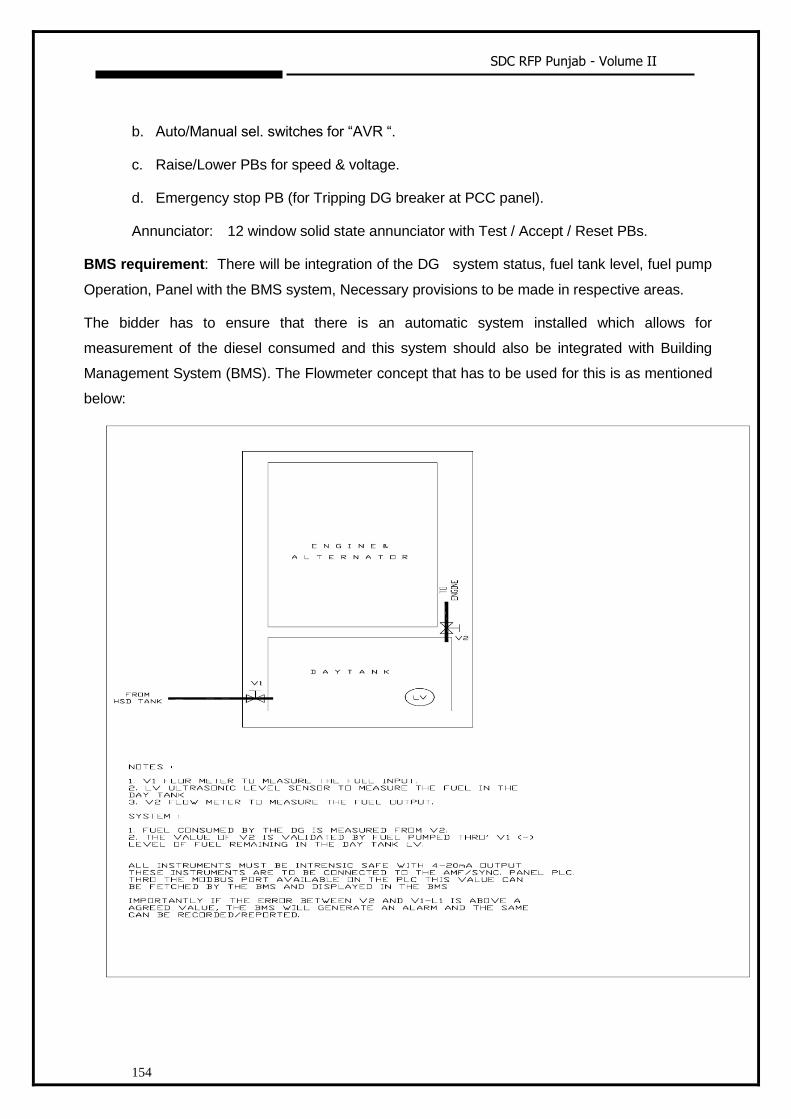
SDC RFP Punjab - Volume II
154
b. Auto/Manual sel. switches for “AVR “.
c. Raise/Lower PBs for speed & voltage.
d. Emergency stop PB (for Tripping DG breaker at PCC panel).
Annunciator: 12 window solid state annunciator with Test / Accept / Reset PBs.
BMS requirement: There will be integration of the DG system status, fuel tank level, fuel pump
Operation, Panel with the BMS system, Necessary provisions to be made in respective areas.
The bidder has to ensure that there is an automatic system installed which allows for
measurement of the diesel consumed and this system should also be integrated with Building
Management System (BMS). The Flowmeter concept that has to be used for this is as mentioned
below:

SDC RFP Punjab - Volume II
155
EXHAUST SYSTEM FOR DIESEL GENERATING SETS
I. SCOPE
The scope of this section is to design, supply, erection, testing and commissioning of D.G
exhaust system in accordance with the prevailing Indian standards and Central Pollution
Control Board norms.
The vendor shall study the location of DG set placement & shall provide the exhaust piping
as per the norms & prevailing condition.
The scope should cover design of system, all necessary calculations, piping, piping
supports, foundations and necessary steel cladding as required.
The vendor should submit all necessary drawings and calculations for approval.
Provision of testing port shall be provided on exhaust pipe line.
II. TESTING
Vendor shall carry out the tests as per codal requirements and CPCB requirement. The
following testing is to be done.
Checking of silencer operation
Checking of surface temperature of exhaust piping
III. MISCELLANEOUS
All allied and implied equipments and accessories required for complete operation of the
system shall be supplied and installed by the vendor, whether specifically mentioned or
not.
The bidder/ supplier shall be responsible for engineering and functioning of complete
system, fully meeting the intent and requirements of the specifications, attached data
sheets/ drawings.
Necessary acoustic doors, acoustic Louvered doors, Ventilation hood for taking hot air
from radiator, all other implied and allied items required for completely making the room
sound proof as per CPCB norms.
Optional to provide factorymade acoustic enclosure with the prevailing norms.
Applicable Standards
The acoustic treatment system / sound proof system shall be in accordance with the
standards given below and any other Indian Standards prevailing at the time of execution.
IS 1950 (1962) – Code of Practice for Sound insulation of Non-Industrial Buildings.
SDC RFP Punjab - Volume II
156
Central Pollution control Board norms with Latest amendments.
Noise and Vibration Control in Diesel Generator Room
The scope of this section consists of noise control measures for the DG set rooms and
ventilation system include sound absorbing treatment to DG room, provision of sound
reducing doors, provision of silencers in the ventilation system and provision of primary
and secondary exhaust mufflers in the engine exhaust piping.
ACOUSTIC TREATMENT
Maximum permissible sound pressure level for the DG sets shall be 60 dBA at 1 m from
the DG room with doors closed. The acoustic treatment shall achieve minimum 25 dBA
insertion loss or meeting the ambient noise standards whichever is higher. If the ambient
noise is higher, the performance of acoustic treatment shall be checked for noise reduction
upto actual ambient noise level, preferably at night times. The measurement of insertion
loss shall be done at different points at 0.5 m from the DG room and then averaged.
Walls and ceiling of DG room shall be acoustically treated by means of minimum 75 mm
thick mineral wool of 64 kg/m3 density to achieve an insertion loss of minimum 25 dBA
and a sound level of max. 60 dBA at 1 m from DG room.
In case the desired reduction in sound level to achieve max 60 dBA outside DG room at 1
m distance (with doors closed) is not achieved with the above treatment, the bidder shall
provide additional thickness of acoustic insulation of the same or modified density to
achieve the required reduction in sound level without any extra cost.
DG bidder shall also coordinate with DG room ventilation bidder regarding acoustic
treatment (if applicable) of fresh air inlets and exhaust outlets to achieve the desired
reduction in sound level outside the DG room.
PERFORMANCE
The specification indicates the general layout and measures required for meeting the end
noise and vibration requirements. The bidder shall include in his offer whatever other
materials are required to be supplied for satisfactory installation and performance of the
system so as to meet the end criteria.
Design Requirements
i. Noise Levels: Noise Level to be achieved outside the D.G room as per CPCB norms.
ii. Layout

SDC RFP Punjab - Volume II
157
Room Size: As per site condition.
iii. Testing
Vendor shall carry out the tests as per codal requirements and CPCB requirement.
iv. Miscellaneous
All allied and implied equipments and accessories required for complete operation of the
system shall be supplied and installed by the vendor, whether specifically mentioned or
not.
CPCB Certificate shall be attained by the vendor after successful completion of the
complete DG installation including the acoustic works.

SDC RFP Punjab - Volume II
158
1.3.1.5 Technical Specifications – Electrical: Low Side
I. GENERAL SPECIFICATIONS
i. SCOPE:
In general, the prime vendor/DCO shall supply, store, erect, test and commission all the
equipment required for Electrical Installation. The DCO shall furnish all the materials,
labour, tools and equipment for the electrical work, and in the bill of quantities and
specifications herein after described.
ii. Prime Vendor/ DCO:
The DCO shall be Class A - licensed electrical contractor, possessing a valid electrical
contractor license in the state, employing supervisors and skilled workers having a valid
permits as per the Regulation of Indian Electricity Rules and Local Electrical Inspector’s
requirements and the same shall be got renewed from time to time.
iii. INFORMATION TO BIDDERS:
a. The design and quality of goods supplied and the workmanship shall be in accordance
with the best engineering practice to ensure satisfactory performance of the system
throughout the service life.
b. The goods and accessories offered shall be complete in all respects. Any material,
and/ or component not specifically stated in this specification which is necessary for
trouble free and successful operation shall be deemed to be included unless
specifically excluded. All such components, accessories, etc., shall be supplied at no
extra cost.
c. The goods supplied shall be such that components, accessories of the same type shall
be interchangeable. Likewise similar or corresponding parts, components/ accessories
shall also be interchangeable.
d. Wherever and whenever a material or article is specified or described by the name of a
particular brand, manufacturer, vendor, the specific item mentioned shall be
understood as establishing type, function, quality and not as limiting brand. However
bidders may offer other similar components/ accessories provided they meet with the
required standards, design, duties and performance. The bidders are free to use any
brand as specified in the list of approved makes and no deviation shall be accepted by
End user.

SDC RFP Punjab - Volume II
159
e. Goods and accessories so offered shall confirm to type tests and shall also be
subjected to acceptance and routine tests in accordance with the requirements
stipulated in this specification.
iv. STANDARDS:
Except as modified by this specification all materials to be supplied shall conform to the
requirements of the latest editions of relevant standards mentioned there in.
v. DEVIATION IN SPECIFICATION:
All deviations in specification shall be brought out by the bidder and detailed clause by
clause.
1. Deviation brought out elsewhere or in any other format will not be considered by the
client and are liable for rejection. It shall also be deemed by the client in such an event
that the bidder has conformed to the clauses in this specification scrupulously.
2. Deviation in specifications shall if possible be quoted with reference to standards. The
bidder shall then furnish an authentic English version of such standards.
vi. LOCAL CONDITIONS:
1. It will be imperative on each bidder to fully inform himself of the local conditions and
factors which may have any effect on the execution of the supply and services covered
under these documents and specification.
2. It shall be understood and agreed that such factors will have been properly
investigated and considered in any bid that is submitted. No claim for financial
adjustments to the contract awarded under these specifications and documents will be
entertained by the purchaser neither change in the time schedule of the contract nor
any financial adjustments arising thereof shall be permitted by the client, which are
based on incorrect information or its effect on the cost of the contract to the bidder.
3. Bidder are advised to visit the various areas where the U.G. Cables/ Earth pits are
going to be installed and assess the problems due to restrictions in access, crossings
to enable them to make proper costing and then quote accordingly.
II. TECHNICAL SPECIFICATION FOR LT PANELS
i. THE POWER CONTROL PANELS
The power control panels shall be metal clad, totally enclosed, rigid, floor mounting, air
insulated, cubical type for use on 415 volts, 3 phase, 4 Wire 50 cycles system. The
SDC RFP Punjab - Volume II
160
equipment shall be designed for operation in high ambient temperature and high humidity
tropical atmospheric conditions. Means shall be provided to facilitate ease of inspection,
cleaning and repairs, for use in installations where continuity of operation is of prime
importance.
ii. The equipment shall be designed to confirm to the requirements of:
a. IS 4237 - General requirements for switchgear and control gears for voltages not
exceeding 1100 volts.
b. IS 2147 - Degree of protection provided by enclosures for low voltages switchgear and
control gear.
c. ARE 375 - Marking and arrangements of bus bars.
Individual equipment housed in the power control to the following IS specifications:
i. Air circuit breakers - IS 2516 (Part I & II/Sec.1) 1977
ii. Fuse switch and switch fuse units - IS 4064 : 1978.
iii. Fuse links - IS 1108 : 1962 or IS 9114 : 1979.
iv. Current Transformer - IS 2705.
v. Voltage Transformer - IS 3156.
vi. Relays - IS 3231.
vii. indicating Instruments - IS 1248.
viii. Integrating Instruments - IS 711.
ix. Control Switches and push buttons - IS 6875.
x. Auxiliary DCOs - IS 2959.
iii. CONSTRUCTIONS:
The power control panels shall be:
i. Of the metal enclosed, indoor, floor mounted free standing type.
ii. It shall be made up of therequisite vertical section, which when coupled together shall
form continuous dead front switch boards.
iii. Provide dust and dump protection, the degree of protection being not less than IP 52 to
IS - 13947.

SDC RFP Punjab - Volume II
161
iv. Be readily extensible on both sides by the addition of vertical sections after removal of
the end covers.
Each vertical section shall comprise:
i. A front framed structure rolled / folded sheet steel channel section of minimum 3mm
thick, rigidly bolted together. This structure shall house the components contributing to
the major eight of the equipment, such as circuit breaker cassettes, fuse switch units,
main horizontal bus bars, vertical risers and other front mounted accessories.
ii. The structure shall be mounted on a rigid base frame of folded sheet steel of minimum
3mm hick and 100mm height. The design shall ensure that the weight of the
components is adequately supported without deformation or loss of alignment during
transit or during operation.
iii. A cable chamber shall house the cable end connections of power / control cable
termination. The design shall be to ensure generous availability of space for easy
installation and maintenance of cabling, and adequate safety for making in one vertical
section without coming into accidental contact with live parts in and adjacent sections.
iv. A cover plate at the top of the vertical section, provided with a ventilating hood where
necessary. Any aperture for ventilation shall be covered with a perforated sheet having
less than 1mm diameter perforated to prevent entry of vermin.
v. Front and rear doors shall be fitted with nuts/ bolts including neoprene gaskets with
fasteners designed to ensure proper compression of the gaskets. When covers are
provided in place of doors, generous overlap shall be assured between sheet surfaces
with closely space fasteners to preclude the entry of dust. The height of the panel should
not be more than 2400mm. The maximum height of any operating mechanism shall not
be more than 2100mm. The total depth should be adequate to cater for proper cabling
space.
vi. Doors and covers shall be of minimum 14 gauge sheet steel. Allsheet steel work forming
the exteriors or switchboards shall be smoothly finished, leveled and free from flaws.
The corners should be rounded.
The apparatus and circuits in the power control panels shall be so arranged as to facilitate
their operation and maintenance and at the sametime to ensure the necessary degree of
safety.
Apparatus forming part of the power control panels shall have the following minimum
clearances:
i. Between phases - 25 mm

SDC RFP Punjab - Volume II
162
ii. Between phases and neutral -25 mm
iii. Between phases and earth -25 mm
iv. Between neutral and earth - 25 mm
If for any reason, the above clearances are not available suitable insulation shall be
provided. Clearance shall be maintained during normal services conditions.
Creepage distances shall comply with those specified in relevant standards. All insulating
materials used in the construction of the equipment shall be arranged in multi-tier
formation, except that not more than two air circuit breakers shall be housed in a single
vertical section. Metallic / insulated barriers shall be providedwithin vertical sections and
between adjacent sections to ensure prevention ofaccidental contact with:
i. Main bus bars and vertical risers during operation, inspection or maintenance of
functional units and front mounted accessories.
ii. Cable termination of one functional units, where working of those of adjacent unit / units.
iii. All covers providing access to live power equipments / circuits shall be provided with tool
operated fasteners to prevent unauthorized access. Provision shall be made for
permanently earthing the frames and other metal parts of the switch gear by two
independent connections.
iv. METAL TREATMENT AND FINISH:
All steel work used in the construction of the switchboards should have undergone a
rigorous metal treatment process as follows:
a. Effective cleaning by hot alkaline degreasing solution followed by cold water rinsing to
remove traces of alkaline solution.
b. Picking in dilute sulphuric acids to remove oxide scales and rust formation, if any,
followed by cold water rinsing to remove traces of acidic solution.
c. A recognized phosphating process to facilitate durable coating of the paint onthe metal
surfaces and also to prevent the spread of rusting in the event of paintfilm being
mechanically damaged. This again, shall be followed by hot waterrinsing to remove
traces of phosphate solution.
d. Passivating in de-oxalite solution to retain and augment the effects of phosphating.
e. Drying with compressed air in a dust free atmosphere.
f. Primer coating, with two coats of highly corrosion resistant primer, applied wet on
stove dried under strictly controlled conditions of temperature and time.

SDC RFP Punjab - Volume II
163
g. A finishing coats (two coats) of power costed to the specified shade of IS.
The total thickness of paint should not be less than 25 microns.
v. BUS BARS
1. The bus bars shall be air insulated and made of high conductivity, high strength
aluminium / electrolytic grade copper complying with the requirement of grade E91E of IS
5082.
2. High tensile bolts and spring washers shall be provided at all bus bar joints.
3. The main phase bus bars shall have continuous current rating throughout the length of
each power control panel, and the neutral busbars shall have a continuous rating of at
least 100% of the phase bus bars.
4. Bus bars shall be colour coded for easy identification of individual phases and neutral
and protective earth.
5. CURRENT TRANSFORMER: Current transformer shall comply with the requirements
of IS 2705. They shall have ratios, outputs and accuracy’s as specified / required
6. INDICATING / INTERGRATING METERS: All indicating instruments shall beof flush
mounting industrial pattern, conforming to the requirements of IS 1248. The instrument
shall have non-reflecting dial, clearly divided and legibly marked scales and shall be
provided with adjusting devices in the front
7. CABLE TERMINATION: Cable entries and terminals shall be provided in the switch-
board to suit the number, type and size of aluminium conductor, power cable and copper
conductor control cable specified in the detailed specifications.
8. Provision shall be made for top or bottom entry of cables as required. Generous size of
cabling chambers shall be provided, with the position of cable glands and terminals such
that cables can be easily and safely terminated. The minimum depth of the panel shall be
restricted to 1600 mm for this purpose.
9. Barriers or shrouds shall be provided to permit safe working at the terminals of one
circuit currents without accidentally touching that of another live circuit. Cabling risers shall
be adequately supported to withstand the effects of rates short circuit currents without
damage and without causing secondary faults. Cable sockets shall be of copper and of the
crimping type as specified.
10. TVSS wherever required must be used in the panels to restrict the surge.
vi. CONTROL WIRING:

SDC RFP Punjab - Volume II
164
1. All control wiring shall be carried out with 1100 V grade single core PVC cable
conforming to IS 694 / IS 8130 having standard copper conductor of minimum 2.5 Sqmm
section for potential circuits and 2.5 mm section for current transformer circuits. Wiring
shall bear neatly bunched, adequately supported and properly routed to allow for easy
access and maintenance.
2. Wire shall be identified by numbered ferrules at each end. The ferrules shall be of the
ring and of non-detoriating materials. They shall be firmly located on each wire so as to
prevent free movement. All control circuit fuses shall be mounted in front of the panel and
shall be easily accessible.
vii. TERMINAL BLOCKS:
Terminal blocks shall be of 500 volts grade of finger touch proof type. Insulating barriers
shall be provided between adjacent terminals.
viii. LABELS:
Labels shall be on anodized aluminum, with white engraving on black background. They
shall be properly secured with fasteners.
ix. TESTS:
Routine tests shall be conducted on each power control panel in accordance with CI 81,
2.2 of IS 8623 and shall comprise:
i. Inspections of the power and control circuits including inspection of wiring and electrical
operational tests where necessary.
ii. Dielectric tests.
iii. Checking of protective measures and electrical continuity of the protective circuits.
x. STORING:
The panels shall be stored in well ventilated dry places. Suitable polythene covers shall be
provided for necessary protection against moisture.
xi. ERECTION:
Switch boards shall be installed on suitable foundation. Foundation shall be per the
dimensions supplied by the panel manufacturer. The foundation shall be flat and level.
Suitable grouting holes shall be provided in the foundation. Suitable MS base channel
shall be embedded in foundation on which the panel can be directly installed. The switch
boards shall be properly aligned and bolted to the foundation by bottom plate or top plate
as the case may be, by using brass Siemens type compression glands. The individual
cables shall then be led through the panel to the required feeder compartments for

SDC RFP Punjab - Volume II
165
necessary terminations. The cables shall be clamped to the supporting arrangements. The
switch board earth bus shall be connected to the local earth grid.
xii. PRE-COMMISSION TESTS:
Panels shall be commissioned only after the successful completion of the following tests.
The tests shall be carried in the presence of SIA’s representative.
a) All main and auxiliary bus bar connections shall be checked and tightened.
b) All wiring terminations and bus bars joints shall be checked and tightened.
c) Wiring shall be checked to ensure that it is according to the drawings.
d) All wiring shall be tested for insulation resistance by a 1000 Volts Megger.
e) Phase rotation tests shall be conducted.
f) Suitable injection tests shall be applied to all the measuring instruments to establish
the correctness and accuracy of calibration and working order.
g) Suitable injection tests shall be applied to all the measuring instruments to
establish the correctness and accuracy of calibration and working order.
h) All relay and protective devices shall be tested for correctness of settings and
operation by introducing a current generator and ammeter in the circuit.
i) High voltage test with 2.5KV for 1 min on power as well as control circuits.
xiii. CIRCUIT BREAKERS:
I. Air Circuit Breakers:
General:
1. Air circuit breakers shall conform to IS 13947-1 /IEC947-1 for general rules and
IS13947 - 2 /IEC947-2 for circuit breakers.
2. ACBs shall be suitable for operation on 3 phase 660 Volts, 50Hz AC supply and
shall have a rated insulation voltage of 1100V AC.
3. All circuit breakers shall be fully tropicalized - (T2) standard and pollution degree
IV.
Type & Construction:
1. The Breaker shall be suitable for rear horizontal & vertical mounting and line load
reversibility, without any deration.
SDC RFP Punjab - Volume II
166
2. The breaker shall comply with isolating function requirement of IS 13947-2/IEC 947 -
2 sec 7.1.2.
3. The breaker shall offer total insulation of the control part with respect to the power
part and preferably shall offer double insulation on the front face (Class II degree of
operating safety).
4. Inspection of the main contacts should be facilitated by a mechanical wear indicator.
Operating Mechanism:
1. ACBs shall be provided with motor operated or manually operated quick make,
quick break, trip-free operating mechanism.
2. Wherever specified, motorised spring charging mechanism suitable for AC or DC
shall be supplied.
Interlocking & safety arrangement:
1. The microprocessor control unit shall be equipped with a push to reset mechanical
indicator, for anti-pumping function.
2. It shall not be possible for breaker to be switched ‘ON’ until it is either in ‘Service’ or
‘Test’ position.
3. The breaker shall be capable of being racked into test or isolated position and kept
locked in any of these positions.
4. It shall not be possible to withdraw the breaker when the springs are charged.
5. It shall not be possible to insert breaker racking handle when cubicle door is open. It
shall have defeat interlock facility.
6. Safety shutters should be closed automatically when ACB is withdrawn
7. OFF position pad-locking arrangement is required.
SDC RFP Punjab - Volume II
167
Rating & Breaking Capacity
1. The rating of the circuit breaker shall be as per the schedule of quantities. The ACB
shall have minimum Service Breaking Capacity (Ics) equal to Ultimate Breaking Capacity
(Icu)
2. The minimum Service breaking capacity (Ics) for rating upto 1600A shall be 65kA and
for rating above 1600A, the service breaking capacity shall be 75kA.
The Short time withstand(Icw) for 1 sec for rating upto 1600A shall be 50kA and for rating
beyond 1600A Short time withstand (Icw) shall be 75kA
Protection:
1. The microprocessor release shall be housed in separate enclosure and there shall be
total insulation of the release with respect to the power circuit.
The microprocessor release shall measure the true rms values to make the measurement
free from the influence of harmonics. The trip-time shall preferably be within 30 ms and
the setting range shall cover the following:
Overload- -circuit - adjustable from 1.5 to 10 times
the rated current (Ir) with time delay setting range from Instantaneous to 0.4 sec
Instantaneous - adjustable from 2 times the nominal current (In) upto the circuit breaker
electro dynamical withstand. It should be possible to switch OFF the Instantaneous
protection to enable total time discrimination upto the breaker breaking capacity.
Earth fault - adjustable threshold (0.2 to In) with time delay setting range from 100ms to
400ms.
Indication of type of fault (O/C, S/C or E/F) locally by LED is preferred.
Local over current pre-trip alarm is preferred by LED on microprocessor release with 2
levels:–
(1) glowing steady when load current reaches 90% of rated current (Ir)
(2) flashing when load current reaches 105% of rated current (Ir)
Thermal Memory: The microprocessor release shall optimize the protection of the
equipment or the circuit conductors in the event of repeated overloads or faults by using
thermal integration to memorize temperature rises.
SDC RFP Punjab - Volume II
168
Safety: Internal overheating of the microprocessor control unit shall be signalled by self
monitoring alarm.
stream MCCBs.
Accessories:
ACB shall be provided with following accessories, if specified in schedule of quantities.
Further these devices shall be field fitable from the front and common for all ratings.
Under -voltage
Shunt-trip
Closing coil
Auxiliary contacts: 4NO+4NC (provision for additional changeover switches wherever
required)
Testing
he ACB as per IS13947-2/IEC947-2 shall be
provided on request.
II. Moulded Case Circuit Breakers:
i. General
Moulded case circuit breakers shall be incorporated in the PCC/MCC wherever required
and shall be of current limiting type and preferably double break.
MCCBs shall confirm to IS 13947-1/IEC 947-1 for general rules and IS 13947-
2/IEC 947-2 for circuit breakers in all respects.
MCCB should be suitable for horizontal & vertical mounting and Line –Load
reversibility and shall be suitable for Isolation.
MCCB shall be suitable for three phase 690 V, 50Hz, AC with a rated insulation
voltage of 750 V AC and impulse withstand of 8 kV.
The MCCB shall be available in three & four pole version (selectable neutral
protection at 0, 50% & 100%).
The MCCB shall provide Class II insulation between the front and internal
circuits.
All the breakers shall have tropicalisation as a standard feature.
Construction:
SDC RFP Punjab - Volume II
169
The MCCB case & cover shall be made of high strength heat resistant and flame
retardant thermosetting insulating mater
quick break trip free type. The operating handle shall have suitable ’ON’,’OFF’,’TRIPPED’
-2/IEC947-
2, the operating mechanism shall be designed such that the handle can only be in ‘OFF’
position.
Three phase MCCBs shall have a common operating handle for simultaneous operation
and tripping of all the three phases.
It shall be possible to “seal on” the thermal-magnetic or electronic trip units to prevent
unauthorized access to the settings.
It should be possible to interchange the trip units at site.
Rating & Breaking Capacity:
The rating of the circuit breaker shall be as per the and schedule of quantities.
The ACB will have minimum service breaking capacity (Ics) equal to Ultimate Breaking
Capacity (Icu)
The Service Breaking Capacity (Ics) in kA for different ratings at 415V AC, 50Hz, at 0.2
p.f shall be as follows:
25kA for ratings upto 100A
35KA for ratings above 100A and upto 250A
45KA for ratings above 250A and upto 630A.
SDC RFP Punjab - Volume II
170
Protection:
All breakers upto 250A shall have thermal-magnetic trip unit with adjustable overload
protection and fixed magnetic protection.
The MCCBs ratings above 250A shall be fitted with electronic trip unit. The overload
setting adjustable from 40% to 100% of the nominal current(In).
It should be possible to have one or more LED indication(s) on the electronic release -
(1) for overload as a pre-trip alarm
glowing at 90% of rated current (Ir).
Flashing at 105% of rated current (Ir).
(2) Fault trip indication by LED locally on the electronic release for O/C, S/C & E/F (if
supplied) wherever release with Communication option (COM) is specified.
The short circuit protection should be adjustable from 2 to 10 times the rated current (Ir).
The Instantaneous Short Circuit protection to be fixed, without any time delay at 11 times
the nominal current (In).
The Earth fault protection, if specified in schedule, shall have adjustable sensitivity with
adjustable time delay settings.
It shall be possible to fully co-ordinate the over-load & short-circuit tripping of the circuit
breakers with the upstream and downstream circuit breakers to provide Total
Discrimination.
Accessories:
MCCBs shall be provided with the following accessories, if specified in schedule and all
these devices shall be fittable at site. Each of these units shall incorporate a pre-wired
terminal strip which is accessible from the front of the breaker without removing the cover.
Preferably, the Shunt trip release and under voltage release shall be snap-in type.
Under voltage
Shunt trip
Alarm switch
Auxiliary switch
Motor operated Mechanism

SDC RFP Punjab - Volume II
171
Interlocking:
MCCBs shall be provided with the following interlocking devices for interlocking the door
of the switchboard. Handle interlock to prevent unnecessary manipulations of the
breaker.
Door interlock to prevent door being opened when breaker is in ON or OFF position
Door-interlock defeat to open the door even if the breaker is in ON position.
Front operated rotary handle should have OFF-position pad-locking facility.
Testing:
Test certificate
Original Test certificate of the MCCB as per IS13947-2/IEC947-2 shall be provided on
request
DCOs
DCOs shall comply with IS 13947 1 for general rules and IS13947-4-1 for standards
pertaining to contactors and motor starters. The contactor shall be capable of
withstanding breaking & making capacities per following:
AC3 Category AC4 Category
Making Current - 10 times Rated Current 12 times rated current
Breaking current - 8 times Rated current 10 times rated current
Contactor shall be capable of withstanding an impulse voltage of 8KV and have an
insulation voltage of 1000V.
The Contactors shall be capable of frequent switching and should operate without any
degradation at 55 deg. C for AC3 application.
The coil shall have 3 terminals and the insulation class shall be preferably H class, to
sustain frequent switching operations. The auxiliary contact block shall have a switching
capacity of 240V at 2A.
Contactors shall have one auxiliary in-built and it shall be possible to have additional NO
& NC contacts in steps of two.
III. Thermal Overload Relay
SDC RFP Punjab - Volume II
172
The Thermal Overload Relay (TOR) shall comply with IS 13947-1 for general rules and IS
13947-1 for standards pertaining to contactor and motor starters and shall be designed
for AC3.
The TOR shall be suitable for Type 1 and Type 2 coordination as per suitable
clause in the relevant Indian Standards.
The TOR shall be capable of offering differential protection and shall be ambient
compensated type, operable upto 70 deg. C.
The TOR shall be capable of withstanding short circuit equal to seventeen times
the rated thermal current (17 Ie).
The TOR will be tripping class 10A as a standard or class 20 for certain
applications where specified.
The TOR should have built in single phasing protection and phase unbalance
protection as per IEC947-4.
It shall be possible to mount the TOR on the underside of the contactor directly.
The design of the terminal shroud shall be such that it offers complete protection
against direct finger contact with the power terminal, as under IP 20 protection.
The TOR shall have in built NO & NC contact.
sealing to make the same tamper proof.
The TOR shall be suitable for Aluminium termination, with a maximum
permissible temperature rise of 65K, at the terminals, with an ambient
temperature of 40 deg. C.
All the TORs shall have tropicalization as IEC 68 series as a standard feature.
IV. Miniature Circuit Breakers (MCB)
MCB casing shall be made of self-extinguishing material, tropicalised treatment 2
(relative humidity: 95% at 55 degrees C).
MCB shall comply with IS8828-1996/IEC 898-1995.
SDC RFP Punjab - Volume II
173
It shall be suitable for use in frequency range 40Hz to 60Hz and shall
accommodate AC/DC supply according to requirements.
Arc chutes should be provided for effective quenching of arc during operations
and fault conditions.
It shall have trip free mechanism and toggle shall give positive contact indication.
It shall be suitable for mounting on 35mm DIN rail/ surface mounting.
Line supply may be connected to either top or bottom terminals i.e there shall be
no line load restriction.
Degree of protection, when the MCB is flush mounted, shall be IP40.MCB & shall
be supplied with clamping terminals fully open.
Contact closing shall be independent of the speed of the operator.
-20 deg C to + 60 deg C
The characteristics should be in accordance with IS8828-1996.The breaking capacity of
the MCB shall be 10kA and energy limiting class 3.
The rated impulse voltage Uimp of the MCB shall be greater than 4kV.
The MCB shall be capable of being used as Incomer circuit breaker and shall be
suitable for use as an isolator.
Electrical endurance of the MCB should preferably be 20,000 opns.
Power loss per pole shall be in accordance with IS8828 - 1996 and the same shall
be furnished by the manufacturer.
In case of multipole MCBs in a single location (DB), it shall be possible to remove
MCB without having to disturb other MCB’s in the vicinity.
1. INSTRUMENT TRANSFORMERS:
a) Current Transformers:
Current Transformers shall be in conformity with IS: 2705 (Part I, II and III) in all respects.
All current transformers used for medium voltage applications shall be rated for 1.1KV,
current transformers shall have rated primary current, rated burden and class of accuracy
as specified in the schedule. However, the rated secondary current shall be 5 A unless

SDC RFP Punjab - Volume II
174
otherwise specified. The acceptable minimum class of various applications shall be as
given below:
Measuring: Class I
Protection: Class 10 P.
Terminals of the current transformers shall be marked permanently for easy identification
of poles. Current transformers shall be provided with Earthing terminals for Earthing
chassis frame work and fixed part of the metal casing (if any). Current transformers shall
be mounted such that they are easily accessible for inspection, maintenance and
replacement. The wiring for CTs shall be copper conductor, PVC insulated wires with
proper termination lugs wiring shall be bunched with cable straps and fixed to the panel
structure in a neat manner.
SDC RFP Punjab - Volume II
175
V. MEASUREMENT INSTRUMENTS:
General:
The digital multi function meter has to have following features
It show the True RMS value
It should display Accurate on distorted waveforms
Low PT, CT burden is essential
CTR & PTR to be user programmable (both primary & secondary)
It has to have Analog load bar for indicating the percentage of load through 12 LED
segments
It should have Bright 8 segment LED for better readability
It can view 3 Parameters together
It has to have Built-in phase analyzer
A 10 year back-up of integrated data is desirable
Accuracy : Class 1.0 as per IEC 62052-11, 62053-21, class 0.5(optional) as per IEC
62052-11, 62053-22 and ANSI C12.20
Universal auxiliary supply - both AC (44-300V) and DC (44 - 300V)
It should work for both HT or LT application
Communication with PCs, PLCs, DCS through optional RS485 Serial Port is required
It has to have Tamper Proof Cover
construction has to be Sealed dust-proof
It has to have Turbo key for quick scrolling through the pages
It has to have Password protection for setup parameters
VI. RELAYS:
a. General
Protection relays shall be provided wherever required to trip and isolate the particular
section under fault. All the relays shall be adjusted and co-ordinate for proper range of
the particular circuit or equipment. Relays shall be provided with flag type indicators to
indicate the cause of tripping. The flag indicators shall remain in position until they are
reset by hand reset. The relays contacts shall be of silver or platinum alloy. The case
shall be dust tight with a finish suitable for tropical country. The relays shall be
capable of disconnecting faculty section of network or faculty equipment without
causing interruption or disturbance to the remaining sections.
SDC RFP Punjab - Volume II
176
b. OVERCURRENT RELAYS:
Combined over-current and earth fault relays:
Over-current relays shall be induction type with inverse definite minimum time lag
characteristics. The over current relays shall be provided with adjustable current and
time settings. The setting for current shall be 50 to 200% in step of 35%. The IDMT
over current relays shall have time lag (Delay) of 0 to 3 seconds. The time setting
multiplier shall be adjustable from 0.1 to unity. Over current relays shall be fitted with
suitable tripping device with trip coil being suitable for operation on 5 amperes. Earth
fault relay shall have current setting of 10% to 40% in step of 10% otherwise; the
earth fault relays shall conform to specification laid down for over current relays.
TESTING:
1. Instrument transformers shall be tested at factory as per IS: 2705 and IS: 3156.The
test shall incorporate routine tests. Original test certificates in triplicate shall be provided.
2. Meters shall be tested as per IS: 1148. The tests shall include routine tests. Original
test certificate in triplicate shall be furnished.
3. Suitable injection tests shall be applied to the secondary:
Circuit of every instrument to establish the correctness calibration and working
order.
All relays and protective devices shall be tested to establish correctness of Setting
and operation by introducing a current generator and an ammeter in the circuit.
SDC RFP Punjab - Volume II
177
1.3.1.6 Technical Specifications – Supply And Installation Of Low Voltage Cables
I. TYPE:
Low voltage cables shall be copper conductor (unless otherwise specifically mentioned
for Aluminium), PVC insulated. PVC sheathed and steel wire armoured or steel tape
armoured construction. The conductors of cable from 16sqmm size shall be stranded.
Sector shaped stranded conductors shall be used for cables of 50sqmm size and above.
The cable shall conform to IS: 1554 part - I in all respects.
The XLPE cables shall be ST HR inner sheathed ST2 - FRLS outer sheathed as per IS –
7098 (Part-1) wire stripped.
II. RATING:
The cable shall be rated for a voltage of 1100 volts.
III. CORE IDENTIFICATION:
Cores shall be provided with the following colour scheme of PVC insulation.
1 Core: Red/ Black/ Yellow/ Blue.
2 Cores: Red and Black
3 Cores: Red, Yellow and Blue
3 1 / 2 / 4 Core: Red, Yellow, Blue & Black.
IV. CABLES AND OTHER ITEMS:
Specifications for XLPE Cables: IS 7098 - Part – I - 1988
Specification for PVC insulated: IS 1554 - 1964 (Heavy duty) electric cables Part -
I For voltage upto 1100 Volts.
Specifications for PVC insulated: IS 694 - 1988 Cables for voltage up to 1100V
Part - II With aluminium conductors.
Glossary of terms for electrical cables: IS 1885 – 1971 and conductors.
Code of practice for safety of buildings : IS 1646 – 1961
(General) Electrical installation.
V. Storing:
All the cables shall be supplied in drums. On receipt of cables at site, the cables shall be
inspected and stored in drums with flanges of the cable drum in vertical position.
SDC RFP Punjab - Volume II
178
VI. Cables in indoor trenches:
Cables shall be laid in indoor trenches wherever, specified. Suitable cables in position.
Trenches shall be filled with steel checkered trench covers.
VII. Cable on Trays / racks:
Cables shall be laid on cable trays/ racks wherever specified. The cables laid shall be
securely fixed to the Cable trays by means of lockable nylon ties. After laying the cables
the cable shall be securely fixed by using 25x3mm GI strips and bolted to the cable tray.
The cost of the nylon ties and the overlapping GI strip shall be included in to the laying
cost of the cable as no separate payment will be made for the overlapping strip and nylon
ties.
VIII. CABLE TERMINATIONS:
Cables jointing shall be done as per the recommendations of the cable manufacturer.
Jointing shall be done by qualified cable jointers. Each termination shall be carried out
using brass compressions glands and cable sockets. Hydraulic crimping tool shall be
used for making the end terminations. Cable gland shall be bonded to the earth by using
suitable size G.I wire / tape.
IX. CABLE TRAYS:
The cable trays shall be of ladder type / perforated steel section slotted angles as
mentioned. The trays shall be complete with plates, Ts, elbows, risers, and all necessary
hardware. The trays shall be galvanised as per IS 2629. The cable trays shall have
suitable strength and rigidity to provide adequate support for all cables. It shall not
present sharp edges, burs of projections, injurious to the insulation of the wiring and
cables. The trays shall be adequately protected against corrosion and shall be made of
corrosion resistant material. It shall have side rails or equivalent structural members.
There shall be a continuous earth strip running on either side of the tray for earthing.
X. CABLE SUPPORT SYSTEM:
The cable tray support system shall have the appropriate factory fabricated components.
It shall be with ceiling support plates anchored with the ceiling with grip bolts. The
perforated trays shall be supported with threaded studs with adjustable clamps and shall
have nuts and washers accessories for leveling.
i. Installation of Cables Trays :
a. Cables trays shall be installed as a complete system. Trays shall be supported
properly from the building structure. The entire cable tray system shall be rigid and
leveled.

SDC RFP Punjab - Volume II
179
b. Each run of the cable tray shall be completed before the installation of cables.
c. In portions where additional protection is required, non combustible covers /
enclosure shall be used.
d. Cable trays shall be exposed and accessible.
e. Where cables of different system are installed on the same cable tray, non
combustible, solid barriers shall be used for segregating the cables.
f. Cable trays shall be grounded by two numbers earth continuity wires. Cables trays
shall not be used as equipment grounding conductors.
g. Cable trays shall be properly leveled and aligned as per the site conditions and a
proper shop drawing shall be produced before starting the work and got approved by
the consultant / project manager.
h. The installation of cable tray support system shall be using the required accessories
as mentioned above and using grip bolts for proper strength in fixing.
i. The separation distance between power and data/telecom cable tray must be
between 1 to 1.5 ft
SDC RFP Punjab - Volume II
180
1.3.1.7 Technical Specifications: Low Voltage Systems
I. DISTRIBUTION BOARDS FOR POWER AND LIGHTING DISTRIBUTION:
i. Distribution boards shall be suitable for 415 volts, 3 phase A.C. supply of 230 volts
single phase A.C. supply as required. Distribution board shall generally conform IS:
2675 or BS: 214.
ii. Type & Construction:
Distribution boards shall be of totally enclosed dead front safety type. The enclosures
shall be made of the best quality sheet steel of not less than 2 mm. The sheet steel shall
be treated with a rigorous rust inhibition process before fabrication. The distribution
boards shall comprise of switch fuse unit or miniature circuit breakers as incoming and
required number of circuit breakers or fuses as out goings. The main and out goings shall
have rating as specified in the schedule. The distribution board shall be provided with
suitable earthing lug.
iii. Bus Bars:
Suitable bus bars made of high conductivity, High Electrolytic grade, Solid copper and
mounted on non-hydro scopic insulating supports shall be provided. Separate earth line
will be provided.
II. Circuit Breakers:
Miniature circuit breakers shall be of approved design and make. Circuit breakers shall be
equipped with individually insulated, braced and protected connectors. The front fact of all
the breakers shall be flush with each other.
III. H.R.C. Fuses:
Rating of the fuses and carriers shall be as per schedule of quantities. Fuse carriers and
bases shall be best grade phenolic mouldings conforming to IS: 1300. They shall be non-
inflammable and non-deteriorating type characteristics. It shall be link type and shall
conform to IS: 1108.
IV. Safety & Interlocks:
All the live parts shall be shrouded such that accidental contacts with live parts are totally
avoided. Distribution boards shall be provided with a front hinged door. Distribution
boards interior assembly shall be dead front with the front cover removed. Main lugs shall
be shrouded. Suitable insulating barrier made of arc resistant material shall be provided
for phase separation. Ends of the bus structures shall also be shrouded.

SDC RFP Punjab - Volume II
181
V. Cabinet design :
The distribution board cabinet shall be totally enclosed type with dust and vermin proof
construction. The cabinet shall be stove enameled. The interior surface shall finished to a
off-white shade. The interior components shall be mounted and locked on to the study
provided inside the cabinet. Over this, a cover made of hylam sheet or stove enameled
sheet shall be provided with slots for operating handle of breakers. The cabinet shall be
equipped with a front door having a spring latch and vault lock. Cabinets shall have
detachable gland plates at both top and bottom.
VI. Terminals:
Distribution boards shall be provided with a terminal block of adequate size to receive
mains and outgoing circuits. The location of the terminal block shall be so located that
crowding of wires in the proximity of live parts is avoided. A neutral link having rating
equal to that phase bus shall be provided.
VII. Directory:
Distribution boards shall be provided with a directory indicating the area or loads served
by each circuit breaker, the rating of breakers, size of conductors, etc. The directory shall
be mounted in metal holder with a clear plastic sheet on inside surface of the front door.
VIII. Installation:
Distribution boards shall be surface mounted recessed mounted as required by the SIA
and at the locations. The boards shall be fixed with suitable angle iron clamps and bolts.
All the cables / conduits shall be properly terminated using gland / grips / check nuts etc.,
Wiring shall be terminated properly using crimping lugs/sockets & PVC identification per
rules.

SDC RFP Punjab - Volume II
182
IX. Testing:
Distribution boards shall be tested at factory as per IS:2675 or BS: 214. The tests shall
include insulation test, high voltage test, etc. Distribution boards shall be tested for
insulation resistance after the erection.
X. UPS OUTPUT PANEL
The PDU should be designed for distribution of power up till rack level keeping in mind
the number of termination required for the entire server farm area. There should be at
least 10 percent of free MCCB in each PDU in case of failure of any connection. Two
separate connections to the rack should be provisioned for the Rack power distribution,
one from PDU-1 (Source UPS 1) and the other in PDU-2 (Source UPS-2).
PVC CONDUITS & ACCESSORIES:
i. CONDUITS
General conduits shall be of PVC extruded with original mix. The wall thickness of
conduits shall be as follows:-
a. 19, 25 & 32mm – 1.5mm or 2mm thick.
b. 38, 50mm and above - 2.5mm thick.
The PVC conduits shall conform to the requirements of IS: (latest edition) in all respects.
The conduits shall have uniform wall thickness and uniform cross section throughout. The
conduit shall be free from burrs. Conduits shall bear the name or trade mark of the
manufacturer on each length. The conduits shall be delivered to the site in original
bundles. Conduits of less than 19mm dia. Shall not be used. Conduits accessories such
as bends, inspection bends, inspection tees, elbows, reducers, draw boxes, junction
boxes, etc. shall be of approved makes. The conduit accessories shall conform in all
respects to IS: 3837. Boxes shall have internally tapped spouts. Junction boxes /
inspection boxes shall be provided with suitable covers. All conduits must be of medium
duty.
ii. INSTALLATION OF CONDUITS:
OPEN / SURFACE CONDUIT SYSTEM:
Wherever, specifically called for, surface conduit system shall be adopted conduits
shall be run in square and symmetrical lines. Before the conduits are installed, the
exact route shall be at site and approval of the user shall be obtained. Conduits
SDC RFP Punjab - Volume II
183
shall be fixed by heavy gauge GI saddles, secured to suitable rawel plugs, at an
interval of not more than 1 meter. Wherever couplers, bends couplers, bends or
similar fittings are used, the saddles shall be provided on either side at a distance of
30 cm from the centre of such fittings. Conduits shall be jointed by means of
screwed couplers and screwed accessories only. In long distance straight runs of
conduits, inspection type couplers or running type coupler’s with jam nut shall be
provided. Threading shall be long enough to accommodate pipes to the full
threaded portion of the couplers, and accessories. Cut end of conduits shall have
no sharp edges nor any burrs left to avoid damage to the insulation of the
conductors. Bends in conduit runs shall be done by bending conduits by pipe
bending machine or any other suitable device as far as possible. Bends which
cannot be negotiated by pipe bends, shall be accompanied by introducing solid
bends, inspection bends or cast iron inspection box. The radius of solid bends shall
not be less than 7.5cm. Not more than three equivalent 90o bends shall be used in
a conduit running from outlet to outlet. Bends shall be properly drained and
ventilated to prevent sweating or condensation inside the pipes. The entire conduit
opening shall be properly plugged with PVC stoppers/bushes. The conduits shall be
adequately protected against rust by applying two coats of approved synthetic
enamel paint after the installation is completed.
Wherever conduits terminate into point control box, outlet box, distribution board
etc., conduits shall be rigidly connected to the box / board with check nuts on either
side of the entry to ensure proper electrical and mechanical continuity. The entire
conduit system after installation shall be bounded to the earth as per the
specifications given in IS 732 and IS 3043.
RECESSED CONDUIT SYSTEM:
All the conduits including, bends, unions, junction boxes, etc., shall be cleaned and
painted with two coats of bituminous paint before they are fixed in position. Conduits
which are to be taken in the ceiling slab shall be laid on the prepared shuddering
work of the ceiling slab before concrete is poured. The conduits shall be properly
threaded and screwed into sockets, bends, junction boxes and outlet boxes and
shall be made watertight by using bituminous hemp yarn at the screwed ends. The
conduits in ceiling slab shall be straight as far as possible to facilitate easy drawing
of wires through them. Before conduits are laid in the ceiling the positions of outlet
points, point controls, junction boxes shall be set out clearly so as to minimize
offsets and bends.

SDC RFP Punjab - Volume II
184
Conduits recessed in walls shall be secured rigidly by means of steel hooks /staples
at 0.8 meter intervals. Before conduit is concealed in the walls, all chases, grooves
shall be neatly made to proper dimensions to accommodate the required number of
conduits. The outlet boxes, point control boxes, inspection and draw boxes shall be
fixed as and when conduit is being laid. The recessing of conduits in walls shall be
so arranged as to allow at least 12 mm plaster cover on the same. All grooves,
chases etc. shall be refilled with cement mortar and finished up to the wall surface
before plastering of walls is taken up by the general DCO. Where conduits pass
through expansion joints in the building, adequate expansion fittings or other
approved devices shall be used to take care of any relative movement. Wherever
conduits terminate into point control boxes, distribution boards etc., conduits shall
be rigidly connected to the boxes; boards etc. with check nuts on either side of the
entry to ensure electrical continuity. Running joints in conduits wherever necessary
shall be rigidly held in aligned position by check nut tightened on running side. After
conduits, junction boxes, outlet boxes, are fixed in position their outlets shall be
properly plugged with PVC stoppers or with any other suitable material so that
water, mortar, vermin or any other foreign material do not enter into the conduit
system. All conduits ends terminating into an outlet, draw box, junction box, point
control boxes etc., shall be provided with bushes of PVC or rubber, after the conduit
ends are properly filled to remove burrs and sharp edges. Concealed conduit laying,
above false ceilings shall be executed in similar manner described above.
Necessary GI pull wires shall be inserted into the conduit for drawing wires and
proper size earth continuity wire shall be run throughout the length of the conduit
with the earth wire being efficiently fastened to the conduit by means of special
clamps.
XI. ENCLOSURE FOR ELECTRICAL ACCESSORIES:
i. Enclosure for electrical accessories such as switches, sockets, fan regulators, etc.
shall be of factory moulded GI boxes conforming to IS: 5133 - Part I. The dimensions
of the enclosures shall be as per clauses 3.1 to 6.31 of IS: 5133. The wall thickness of
GI enclosure shall not be less than 1.6 mm. The enclosure boxes shall be provided
with a minimum of four fixing lugs located at the corners for fixing the covers. all fixing
lugs shall have tapped holes to take machined brass screws.
ii. 3.2 Sufficient number of knock-outs of 38mm/ 32mm/ 25mm dia. shall be provided for
conduit entries. Enclosures shall be sufficiently strong to resist mechanical damage
under normal service conditions, provision shall be made for bonding the enclosures

SDC RFP Punjab - Volume II
185
to the earth. The enclosures shall be adequately protected against rust and corrosion
both inside and outside.
XII. WIRING CONDUCTORS:
i. All wiring conductors shall be PVC insulated, stranded aluminium conductors of
1100 V grade. Wiring conductors shall conform in all respects IS: 694 Part-II
(latest edition). Wiring conductors shall be supplied in Red, Black, Yellow, Blue
colours for easy identification of wires. The wiring conductors shall be supplied in
sealed coils of 100 mtr length. The wiring conductors shall bear manufacturer’s
trade mark, name, ISI mark, voltage grade, etc.
ii. Installation of wiring conductors/ cables: The wiring conductors shall not be drawn
into the conduits / wire ways until all the works of any nature that may cause
damage to the wires are completed. Proper care shall be taken in pulling the wires
to see that no damage occurs to the insulation of the wires. The installation and
termination of wires shall be carried out with due regard to the followings.
a. While drawing the wiring conductors, care shall be taken to avoid
scratches and kinds which cause breakage of conductors. There shall be
no sharp bends in the conduit system.
b. Insulation shall be shaved of like sharpening a pencil.
c. Strands of the wires shall not be cut for connecting to the terminals or lugs.
d. The terminals shall have adequate cross section to take all the strands.
e. Ends of the wiring conductors shall be terminated by using crimping
sockets.
f. Soldering of sockets shall not be done. Ends of the conductors terminating
into a switch / socket / connector shall be soldered.
g. Oxide inhibition grease shall be applied at all terminals and connections.
h. Brass flat washers of large area shall be used for bolted terminals.
i. Bimetallic connectors should be used wherever aluminium conductors are
tapped from copper mains or vice-versa.
iii. Wiring for power and lighting circuits shall be carried out separately and distinct
wiring systems. Wiring for emergency system shall also be carried out in a
separate and distinct wiring system. Balancing of circuits in a three phase
system shall be arranged before the installation is taken up. Wiring conductors

SDC RFP Punjab - Volume II
186
for 3 phase, 4 wire system shall be of 1100 volts grade and that for single
phase, 2 wire system shall be of 650 volts grade.
iv. The wiring system envisaged is generally shown on the layout drawings and line
diagrams. However, a brief account of the general wiring system is given below.
a. Sub mains wiring - wiring from switch boards to the individual distribution
boards.
b. Circuit wiring - wiring from DBs to the point control boxes for lighting,
fans, 5A sockets, etc. and from DBs to the power sockets in the case of
power wiring.
v. The sub-main wiring shall be either in 3 phase 4 wire or single phase, 2 wire
system.Each sub main wiring circuit shall also have its own copper earth
continuity wire.The number and size of copper earth continuity wire shall be as
per the detailed drawings and specifications.
vi. Circuit wiring shall be in single phase system. However, a maximum of 3 to 4
single circuits belonging to the same pole/phase could be installed in the same
conduit or raceway.
vii. The wiring shall be complete in looping system.
Each circuit wiring shall be provided with suitable copper earth continuity
conductor. Not more than eight light points/fan points shall be grouped on one
lighting circuit. The load per circuit shall not exceed 750 watts. All the wiring
shall be carried out in looping-in-loop system. The maximum number of various
size conductors that could be drawn into various sizes of conduits shall be as
per table II of IS: 732 (Latest Edition). The wiring shall be colour coded for easy
identification of phases and neutral the following colour codes shall be adopted:
Phase
R - Red
Y - Yellow/White
B - Blue
Neutral - Black
Earth - Green
viii. All circuit wiring shall be provided with printed PVC identification ferrules at
either end bearing the circuit number and designation.

SDC RFP Punjab - Volume II
187
ix. Flexible conduit shall be used for dropping from ceiling complete with couplings
for dropping circuits and point wiring for connecting up the lighting fixture
XIII. SWITCHES, SOCKETS AND MODULAR ACCESSORIES:
1. General Requirements: Light control switches shall be of a 5A rating. Light control
switches shall be of piano-key type design suitable for flush mounting for general lighting.
Wherever specifically called for tumbler type switches shall be used for surface
mounting.Light control shall have either integral mounting plates or white PVC/Perspex
cover plates as approved.
2. All sockets, 5A & 15A ratings, shall be of flush mounting type with control switches
of piano- key type design of the same rating as that of the sockets. All sockets outlet shall
be of 3 pin / 5 pin type. The socket shall be of high quality polycarbonate with pins made
of brass alloy and plated with a noble metal. Sockets shall be provided with PVC surface
outlet plates with round corners and beveled edges. All the sockets shall be provided with
plug tops of approved quality and design.
3. Industrial type sockets: Industrial type sockets shall be provided wherever
specifically called for.industrial sockets shall be totally metal clad with porcelain base
incorporating the pins. Sockets shall have 3 pins for single phase applications and 4 pins
and scraping earth of 3 phase applications. The sockets shall be provided with suitable
metal clad plug top with suitable cable entry. Sockets shall have metal covers with chain.
It shall have a suitable interlocked switch. Industrial type sockets shall be provided with a
suitable sheet steel housing made of 16 gauge with the socket mounted in flush with
cover of the housing.
4. Lamp holders, ceiling roses etc. Accessories for light outlets such as lamp
holders, ceiling roses etc. shall be in conformity with requirements of relevant IS
specification. Only approved make of accessories shall be supplied.
5. Installation of switches, sockets & accessories: All the switches shall be wired on
phases. Connections shall be made only after testing the wires for continuity, cross phase
etc., with the help of a megger.
Switches, sockets fan regulators etc., shall be housed in proper GI factory boxes. The
arrangement of switches and sockets shall be neat and systematic. Covers for enclosure
shall be moulded accommodating switches, sockets etc., Outlets shall be terminated into
a ceiling rose for fan points. For wall plug sockets, the conductor may be terminated
directly into the switches and sockets.
The outlets, point control boxes etc. shall be setout as shown on the drawings. Before
fixing these, the DCO shall obtain clearance from the SIA / consultant / project manager

SDC RFP Punjab - Volume II
188
with regard to their proper locations. The enclosure of sockets and 3rd pin of the sockets
shall be connected to the ground through a proper size earth continuity wires.
XIV. POINT WIRING:
Point wiring shall commence from the first point control box/local control box for the points
connected to the same circuit. Point wiring for lights, fans 5 A sockets, call bells etc. shall
be carried out with PVC insulated wires. Only 2.5mm2 wires shall be used. The point
wiring shall be inclusive of 25mm / 32mm rigid pvc conduits of standard and approved
make (as specified herein before) along with approved quality conduit accessories such
as bends inspections bends, reducers, junction boxes etc. together with wiring
accessories such as ceiling roses, lamp holders, connectors, point control boxes
(enclosure for electrical accessories) etc., Point wiring shall be provided with 14 SWG
Copper earth continuity wire for earthing 3rd pin of sockets, luminaries and fan fixtures.
Light control shall be either single, twin or multiple points controlled by a switch as
specified.
XV. TESTING OF ELECTRICAL INSTALLATIONS:
i. Testing of installation shall be as per IS: 732-1963.
a. The insulation resistance shall be measured by applying suitable pressure
between earth and whole system of conductors or any section thereof with
all fuses in places and all switches closed and except in earthed
concentric wiring all lamps in position or both poles of the installation
otherwise electrically connected together, where a direct current pressure
of not less than twice the working pressure provided that it does not
exceed 500 volts for Medium Voltage circuits. Where the supply is derived
from the three wire (A.C. or D.C.) or a poly phase system, the neutral pole
of switch is connected to earth either direct or through added resistance,
the working pressure shall be deemed to be that which is maintained
between the outer or phase conductor and the neutral.
b. The insulation resistance measured as above shall not be less than 50
megohms divided by the number of points on the circuits, provided that the
whole installation shall be required to have an insulation resistance greater
than one megaohm.
c. Control rheostats, heating and power appliances and electric signs , if
required, be disconnected from the circuit during the test but in the event
of the insulation resistance between the case or frame work and all live
parts of each rheostat appliances and sign shall not be less than that

SDC RFP Punjab - Volume II
189
specified in relevant Indian Standard Specifications or where there is no
such specification shall not be less than a half mega ohm.
d. The insulation resistance shall also be measured between all conductors
connected to one pole or phase conductor of the supply and all the
conductors connected to the middle wire or the neutral or to the other pole
or phase conductors of the supply and its value shall not be less than
specified in sub clause (b).
ii. Testing of Earth continuity path:
The earth continuity conductor including metal conduits and metallic envelopes in all
cases shall be tested for electric continuity and the electrical resistance of the same along
with the earthing lead but excluding any added resistance or leakage circuit-breaker
measured from the connection with the earth electrodes to any point in the earth
continuity conductor in the completed installation shall not exceed one mega ohm.
iii. Testing of polarity of non-linked single pole switches:
a. In a two wire installation, test shall be made to verify that all non-linked single pole
switches have been fitted in the same conductor throughout and such conductor
shall be labeled or marked for connection to an outer or phase conductor or to the
non-earthed conductor of the supply.
b. In a three wire or a four wire installation, a test shall be made to verify that every
non-linked ingle pole switch is fitted in conductor which is labeled or marked for
connection to one of the outer phase conductors of the supply.

SDC RFP Punjab - Volume II
190
1.3.1.8 Technical Specifications – Light Fixtures
I. GENERAL :
1. The light fixture shall be as per the catalogue number specified.
2. The fixture shall be complete with the required lamp / fluorescent tube and the starting
inductor.
3. The fixture shall be high P.F correction type.
4. All electronic chokes shall be with less than 8% harmonic output.
5. All this shall have proper earthing facility to take care for eddy currents.
6. The fluorescent tubes shall be TL-5 high efficiency with minimum color rendering
index of 82.
7. STROBOSCOPIC EFFECT: The fixture shall have no stroboscopic effect under
normal voltage conditions.
8. The normal life of fluorescent lamps shall not be less than 7500 Hours.
9. The IP classifications shall be as per IEC-529 and as follows.
a. Office interiors / corridors - IP-20.
b. The outdoor streetlights - IP-43.
c. Underwater fitting - IP-67.
10. The color rendering index of lamp shall be CRI-Ra 80-90.
11. The fixture shall be class 1 safety level as per IEC.
12. The fixture shall be suitable for an atmospheric temperature of 35oC.
13. For mirror optic fixtures only mat finish parabolic side reflectors shall be used and
shall confirm to CIBSE-LG3-1975.
14. The fixtures to be fixed to the false ceiling shall have a clip-on mechanism for fixing.
15. The fittings shall be mounted with G.I chain/2 runs of G.I. wire for hanging the fittings
fixed with anchor bolt to the ceiling.
16. It shall never be fixed resting on to the grid of false ceiling or on the AC ducting.
17. All the fixtures shall be with loop in or loop out wiring facility.
18. The inter wiring of fixtures shall be with class –H insulation.

SDC RFP Punjab - Volume II
191
1.3.1.9 Technical Specification - Earthing System
I. GENERAL
All non-current carrying metal parts of the electrical installation shall be earthed as per
IS:3043 and with subsequent amendments. All metal conduits, trunkings, cable sheathes,
switchgear, distribution boards, meters, light fixtures, fans and all other metal parts
forming part of the work shall be bonded together and connected by two separate and
distinct conductors to earth electrodes. Earthing shall also be inconformity with the
provisions of rules 32, 61, 67 and 68 of IER-1956.
II. EARTHING CONDUCTORS
All earthing conductors shall be of high conductivity copper or GI as required /specified
and shall be protected against mechanical damage and corrosion. The connection of
earth continuity conductors to earth bus and earth electrode shall be strong and sound
and shall be easily accessible. The earth conductors shall be rigidly fixed to the walls,
cable trenches, cable trays or conduits and cables by using suitable clamps.
1. Main earth bus shall be taken from the main medium voltage panel to the
earth electrodes. The number of electrodes required shall be arrived at taking in to
consideration the anticipated fault on the medium voltage network.
2. All the sub-mains and sub-circuits shall be provided with earth continuity
conductors as specified and connected to the main earth bus. Earthing
conductors for equipment shall be run from the exposed metal surface of the
equipments and connected to a suitable point on the sub-main or main earthing
bus. All switch boards, distribution boards and isolators, disconnect switches shall
be connected to the earth bus. Earthing conductors shall be terminated at the
equipment using suitable lugs, bolts, washers and nuts. All conduits, cable
armouring, raceways, rising mains, metal boxes, panel boards etc., shall be
connected to the earth all along their run by earthing conductors of suitable cross
sectional area. Sprinkler pipes, water pipes, steel structural elements, lighting
conductors shall not be used as a means of earthing an installation. The electrical
resistance of earthing conductors shall be low enough to permit the passage of
fault current necessary to operate a fuse / protective device / a circuit breaker and
shall not exceed 1Ohm.
III. EARTHING ELECTRODES
i. PLATE ELECTRODE

SDC RFP Punjab - Volume II
192
Plate electrodes shall be made of copper plate of 3.15 mm thick and 60 x 60 cm
size. The plate shall be burried vertically in ground at a depth of not less than 2
meters to the top of the plate, the plate being encased in salt and charcoal to a
thickness of 15 cm all round. It is preferable to burry the electrode to a depth
where subsoil water is present. Earth leads to the electrode shall be laid in a GI
pipe and connected to the plate electrode with brass, bolts, nuts and washers. A
GI pipe of not less than 25mm dia. Shall be placed vertically over the plate and
terminated in a funnel at 5 cms above the ground. The funnel shall be provided
with a wire mesh. The funnel shall be enclosed in a masonry chamber of 45 cm x
45 cm x 30 mm dimensions. The chamber shall be provided with heavy duty
C.I.cover and C.I. frame. The earth station shall also be provided with a suitable
permanent identification using painting.
ii. PIPE ELECTRODE
Pipe electrode shall comprise of a 3 mtr long 38mm dia class ‘B’ GI pipe burried
vertically in a pit of 35cm x 35 cm size and filled with alternate layers of charcoal,
salt and connected at the top to a Class ‘B’ GI pipe of 25mm, 1 meter long with a
funnel at the other end, 5 cms above the ground. The earth lead shall be properly
bolted to the pipe electrode with brass bolts, nuts and washers. The funnel and
earth lead connections shall be enclosed in a masonry chamber of 30m cms x 30
cms. 300 dimensions. The chamber shall be provided with heavy duty C.I. cover
and C.I. frame. Proper permanent identification tag / label shall be provided for
each electrode using painting.
iii. EARTH MAT :
The earth mat shall be provided as per the sketch and as detailed in drawing.
IV. PRECAUTIONS
Earthing system shall be mechanically robust and the joints shall be capable of
retaining low resistance, even after passage of fault currents.Joints shall be
welded, bolted or double-reveted. All welded joints are painted with cold Zinc
galvanising paint. All the joints shall be mechanically and electrically, continuous
and effective. Joints shall be protected against corrosion.
V. TESTING
On the completion of the entire installation, test on earth resistance of electrode
shall be conducted.

SDC RFP Punjab - Volume II
193
1 All meters, instruments and labour required for the tests shall be provided by the
DCO. The test results shall be submitted in triplicate to the SIA / consultants /
project manager for approval. Tests shall be conducted in the presence of
Engineer-in-charge.
SDC RFP Punjab - Volume II
194
1.3.1.10 Technical Specifications – Change Over Switch for PAC
PAC changeover switch will accept two inputs from two different panels and provide one
output to the PAC. This is basically to build 100% redundancy of power for the PAC. The
COS will be consisting of the following
2 nos 60A (min) 4P AC3 Contactor with Mechanical Interlock.
2 nos No. ON delay Timers
1 No. Auto Manual Selector Switch
Sets of On/ Off Push button.
1 No. Priority Selector Switch.
No. 2NO+2NC Aux. Contactors for Status indication to BMS.
Sets of RYB Phase Indication Lamps.
Sets of ON/OFF Indication Lamps.
1 Set of Control Terminal Blocks.

SDC RFP Punjab - Volume II
195
1.3.1.11 Technical Specifications – Air Conditioning
1.3.1.11.1 Precision Air Conditioning
I. Precision Air conditioner units I. Precision Air conditioner units
The Precision Air conditioner shall be High sensible cooling capacity and high SHR (i.e.
the sensible to total cooling capacity ratio). Low running costs, achieved by means of
sophisticated design and co-design methods, combined with an accurate selection of
the components. The whole range of units shall be “environment friendly” because it
uses materials that can be recycled, particularly for the plastics and the thermal
insulation. The rating required is 12Tr sensible capacity with min 7000 cfm for each.
Total no of PAC required is 6 nos.
II. Cabinet Construction
All versions shall be enables to access all the main components of the machine from the
front for installation purposes and routine servicing. With this feature, the machines can
be installed side by side, or in between cabinets for other technical applications (racks).
Outside panels shall be coated with epoxy-polyester paint, which guarantees the long-
term durability of their original features. The front panels are attached to the framework by
means of rapid-coupling “fasteners”. The standard panels are lined on the inside with
heat- and sound-proofing insulation to class 1.
III. Fans
Aluminium single-inlet centrifugal fans with backward curved blades with a low moment of
inertia and innovative vane profile shall be provided. The directly-coupled electric motor is
of the three-phase (or single-phase in outside-rotor type protection grade IP10, offering
the opportunity for speed adjustment by means of an auto-transformer and complete with
thermal protection inside the electric motor winding. Using this type of fan with a highly-
reactive fan wheel instead of the one with forward curved blades enables you to reach
higher useful static pressures (up to 350 Pa) AS A STANDARD FEATURE.
SDC RFP Punjab - Volume II
196
IV. Evaporator Coil
Heat exchanger (evaporator coil) shall be designed with an ample front surface area in
order to ensure a low air flow velocity through the exchanger so as to prevent the
entrainment of droplets of condensation, reduce the air’s load losses and ensure a more
efficient heat exchange during both the cooling and the dehumidifying processes.
The exchanger is composed of copper tubes mechanically expanded on aluminium fins,
complete with a hydrophilic treatment to reduce the surface tension between the water
and the metal surface, thus favoring film-wise condensation.
The exchanger is situated upstream from the fans to ensure unhindered air distribution
and is complete with a stainless steel condensate tray with a flexible conduit for its
drainage and an incorporated trap.
V. Filtration
Air filters of box type, made of self-extinguishing, artificial-fiber cellular material or dry
media G4 type Filter. Low airflow and clogged filter alarm sensors for controlling the
operating conditions of the fans and the build-up of dirt on the air filters inside the unit.
VI. Compressor
Latest-generation hermetic scroll compressors (air- and water-cooled DX versions),
characterized by a high COP (coefficient of performance) and consequently also a high
energy efficiency.
VII. Refrigerating circuits (air-cooled DX versions)
Each circuit is composed of as standard, a fluid intake complete with a rotalock on-off
cock and safety valve, a dehydrating filter and flow sensor. The former enables the
refrigerating circuit to be kept free of humidity (thus increasing the life of all the circuit’s
components), while the latter enables a rapid check on whether the system is charged
with refrigerant correctly and whether it contains any humidity.
Electronic Expansion Valve (EEV) / Thermal expansion valve ( TEV) This enables to
adjust the flow of refrigerant fluid through the evaporator, controlling the real evaporator
superheating in relation to variations in the ambient conditions in the room being air-
conditioned. Improving in this way precision of cooling and the energy efficiency of the
cooling cycle.
Liquid receiver with safety plug installed inside the unit (in the air-cooled DX versions)
SDC RFP Punjab - Volume II
197
VIII. Remote air-cooled condenser
These condensers are characterized by a single- or dual-circuit exchanger with
aluminium finned copper tubes, complete with low-speed axial-flow fans to reduce the
sound pressure level. The frame is made of embossed aluminium with excellent weather-
resistant characteristics. The remote condenser is complete with an electric power and
control board, fully wired and tested at the factory. Condensers shall be suitable for 24
hours operation and be capable of providing vertical or horizontal discharge
IX. Electrical Heating
Electric heating with aluminium-finned heating elements, complete with safety thermostat
for manual resetting to cut off the power supply and trigger the alarm in the event of
overheating. Thanks to the low surface temperature of the heating elements, the air
ionization effects are also limited. This heating system serves a dual purpose:
heating the air in order to reach and maintain the set point; reheating in the dehumidifying
phase, so as to restore the air temperature to the set point. As a result, the installed
heating capacity is sufficient to maintain the dry bulb temperature in the room during
operation in dehumidifier mode.
X. Humidifier
Immersed-electrode humidifier for modulating sterile steam production with the
automatic regulation of the concentration of salts in the boiler to allow for the use of
untreated water. Proportional control of the humidifier’s operation (achieved by controlling
the electric current allowed to pass through the cylinder’s electrodes) and the periodic
flushing cycle (controlled by continuously monitoring the water’s conductivity) guarantee a
perfect efficiency of the system, a low energy consumption and a greater durability of the
components.
XI. Switch Board
Switchboard shall be situated in a compartment separated from the air flow and made in
compliance with the directive 73/23/EEC and related standards. The main characteristics
are 24V ac low-voltage secondary circuit with isolation transformer, plastic insulating
screen for protection from live components, general isolator with mechanical interlock,
thermo magnetic circuit-breakers for protection, terminal board for no-voltage signal and
control contacts. All the units must undergo a safety test cycle to check the continuity of
the protection circuit and the insulation resistance, and a voltage (dielectric strength) test.
XII. Microprocessor control system
SDC RFP Punjab - Volume II
198
The microprocessor controller manages the unit operations autonomously. In direct
expansion unit the alghoritms permits integral management of the EEV/ TEV with
consequent optimisation of energy saving, constant air flow during
dehumidification and absolute operating stability. Units have been designed and
developed to interact with all the most widely used Building Management Systems,
exchanging data via the most common communication protocols through serial
connections.
The user terminal is fitted with a backlit LCD display and keys to move between and
change parameters. It can be situated on board the machine or, on request, with a kit for
wall mounting for the remote control of the unit. By means of the user terminal one can
set the air-conditioner’s operating parameters, monitor the trend of the main working
parameters and read any alarm messages.
The microprocessor control system can be supplied with the following optional cards:
RS485 serial adapter for data transfer to a central supervisor system with STD
protocoll or MODBUS protocoll;
Clock card for managing scheduling operations and for the operations counter
functions
WATER LEAK DETECTOR comprising a control module installed on the electric
switchboard and an external sensor.20
1.3.1.11.2 Technical Specifications – Comfort AC
Supply/ Installation/ testing and commissioning of various type of ACs scush as window
type, Cassette Type individual AC of and Multi split AC of suitable nominal cooling
capacity fitted with hermetically sealed compressors operating on R-22/ Non CFC
suitable for Ceiling Mounting, comprising of ½ room units and one no condensing units
suitable for operation on 230 V, 50 Hz, single phase, or 415 V, 50 Hz, three phase, AC,
supply complete with remote control, capable of performing
Cooling
Dehumidifying
Air Circulating
Filtering
Installation of AC includes:-
Mounting / Fitting indoor & outdoor unit at their respective location.

SDC RFP Punjab - Volume II
199
Laying Refrigerant pipelines as required at site and connecting both the unit after drilling
hole/holes in the wall. The thickness of Cu tubing shall not be less than 0.80 mm.
Insulating the suction pipe with expanded polythene foam tubing.
Supply & Installation of drain pipe, to drain out the condensate water being formed in the
indoor unit.
Charging of Refrigerant gas in the unit.
Provision for PVC/ Plastic channel for concealing the channel and painting matching with
interiors.
Drain pipe.4 / 6 sq mm 3 / 4 core PVC insulated copper wire as per requirement to
electrically connect both the units with each other.
Required plumbing for drain pipe
SDC RFP Punjab - Volume II
200
1.3.1.12 Technical Specification – Integrated Building Management System
SECTION – I
INTEGRATED BUILDING MANAGEMENT GUI SOFTWARE
Integrated Building Management GUI software shall be high-performance, building
automation system for monitoring and managing building’s devices and systems,
including HVAC, lighting, hydraulics, water, electrical equipment and more. An application
of Buildings Integrator platform utilizes open system standards to seamlessly integrate
every control and information system within the facility / enterprise.
Buildings Integrator platform shall have single-window control over all building operations,
and all the relevant data which need to maximize building performance. In addition,
Building Manager captures current and historical data for advanced analysis and
reporting and will install, customize, and maintain Building Manager to all requirements to
create the ideal solution for a wide range of operations.
Specification
Total integration of Access Control, Security, Surveillance, Heating Ventilation and Air
Conditioning, Energy Management and Life Safety systems
Integration with a diverse range of devices, enterprise systems, Internet and
intranet sources allowing intelligent management of key facility information
Uses industry-standard hardware and Windows XP, 2000 and 2003 operating
systems
Supports the leading open standards: BACnet, ODBC, and Modbus
UL Listed to Standards UL864 (Fire), UL2017 (Signaling Systems), UL916
(Energy Management Systems), UL1017, UL1076 (Security), UL1610 (Central
Station) and UL294 (Access Control)
Easy-to-use Web-based user interface reduces operator training costs and puts
the user in control of every situation
Suitable for use in a restricted Pharmaceutical environment requiring
conformance to 21 CFR Part 11 for electronic records and electronic signatures
Designed and developed to International Standards ISO 9001 for quality
Seamless integration
I. BUILDING MANAGEMENT
SDC RFP Punjab - Volume II
201
Enterprise Buildings Integrator platform shall meet building management and monitoring
of PAC control needs by providing interfaces to leading open system solutions and HVAC
devices.
II. SECURITY MANAGEMENT
Enterprise Buildings Integrator platform collects information from security, access control
and surveillance devices, ensuring protection of people, assets and intellectual property.
III. LIFE SAFETY MANAGEMENT
Enterprise Buildings Integrator platform allows monitoring and control of fire alarm
systems for fire protection and smoke control. Enterprise Buildings Integrator platform
shall available with UL864 Listing for Ethernet based life safety control and monitoring.
IV. DIGITAL VIDEO MANAGEMENT
Enterprise Buildings Integrator platform allows surveillance of your facility using cameras
connected directly to your LAN, enabling flexible event based recording and viewing.
V. ENERGY MANAGEMENT
Enterprise Buildings Integrator platform monitors, validates and optimizes your energy
usage enabling you to help the environment while saving money.
1. SYSTEM ARCHITECTURE
Enterprise Buildings Integrator platform has client/server architecture. It provides a
scaleable system that accommodates configurations ranging from a small single-node
system to an extended system with multiple servers and Stations connected across LANs
or WANs.
Distributed System Architecture
Enterprise Buildings Integrator platform Servers can also be connected together in a
Distributed System Architecture, allowing very large or geographically distributed sites to
be operated as a single system. Alternatively, this architecture allows autonomous
Enterprise Buildings Integrator platform nodes to communicate alarms and cardholder
information through a network with a minimum of engineering effort.
A Distributed System Architecture enables multiple facilities to be operated in an efficient
and consistent way across your entire organization without sacrificing the independence
of each office.
SDC RFP Punjab - Volume II
202
In addition seamless system Integration, Enterprise Buildings Integrator platform provides
an open system architecture which combines a variety of controllers, standard hardware
devices, and communications interfaces into one, integrated, central system that
maximizes the performance of your building or facility. Enterprise Buildings Integrator
platform can integrate with the following subsystems:
Access controllers and access card readers
Security monitoring
HVAC monitoring and control
Life safety monitoring and control
Energy usage monitoring
Lighting control
Analog CCTV systems
LAN/WAN based Digital Video Manager
Industrial process controllers
Enterprise management systems
Time and attendance
Asset and people tracking
Maintenance management
Web, Internet and intranet pages and systems
Alarm paging and SNMP notification systems
2. OPEN SYSTEMS SUPPORT
In addition to being based on a range of open technologies, It supports a wide variety of
open systems. Standards for integrating other systems or subsystems. The Open System
standards supported are listed in the following sections.
BACnet; Supports ASHRAE Standard for the BACnet Protocol, implementing both
BACnet Operator Workstation and BACnet Gateway functionality. It supports BACnet
over Ethernet and IP communications. A BACnet PICS document is available on request
which details It support for BACnet Standard Objects and Application Services.
OPC: Supports OLE for Process Control (OPC) 2.0 Data Access. This interface allows
reading and writing to an OPC Data Server as an OPC client. This capability provides
access to a wide range of third-party OPC Data Servers.
MODBUS; Support general-purpose interface and de factoy standard communications
protocol that can be used to integrate different controllers.
3. OPERATOR INTERFACE
SDC RFP Punjab - Volume II
203
The operator interface allows a user to perform the following tasks:
Display and control field equipment
Acknowledge alarms on a priority basis
Display point status and history information
Display information about cardholders
Define and alter time schedules
Initiate printing of reports
View, archive and retrieve event logs
Monitor data communications channels
Configure system parameters
Select and control CCTV cameras
Build points
Create color graphic displays
Display information from Internet and intranet sites
Record and play back digital video
View and track moving assets or people
Responding to alarms is crucial and an operator always needs to see the most important
alarm. In Station, there is a dedicated alarm line which indicates the most recent, highest
priority, unacknowledged alarm.
Stations also display status information, including:
All points of a certain type in a particular state
Points in alarm pending acknowledgment
Points in alarm which have been acknowledged
Communication failures
Stations and printers currently off-line
Fire detection points status
4. HMIWeb
Custom displays are created using HMIWeb Display Builder. A typical custom display
includes a static background, and dynamic objects that indicate the status and alarm
condition of relevant devices. Popup faceplates showing more information about a device
can also be used. Also, controls, such as buttons, can be added so that users can
execute tasks, call up other displays and generate reports. The HTML format of custom
displays provides easy interoperability with other Web technology.
SDC RFP Punjab - Volume II
204
Web Enabled
HMIWeb displays make use of Web technologies. Not only can they be created
with native HTML content, they can be viewed in either Station or in Windows
Internet Explorer. Full control of your facility is possible through a browser.
Operator Security: Offers sophisticated methods for controlling access to
sensitive data.
Security and Control Levels, it is possible to restrict and control what activity
operators can perform by giving them different security levels. The system
supports six different levels of operator security. In addition to this; this
incorporates control levels to limit manual control of doors, locks or sensors. Only
operators with appropriate control levels can issue commands to these points and
can also restrict the commands an operator can issue, for example an operator
may be allowed to lock a door but not unlock it.
Compliance to 21 CFR Part 11
In highly regulated environments such as Pharmaceutical processing plants, a
supervisor must formally approve any changes to a validated environment. It
provides supervisors the ability to review and approve changes to the system
configuration using electronic signatures. An electronic signature can be either a
single or a double signature and “signing” requires operators to re-enter their
password along with reasons and meanings behind the change in the system.
5. Schedules
Schedule shall provide extensive scheduling functions both from the server itself and
from controller-specific schedules. Occupancy scheduling can be defined by selecting the
appropriate dates and times from a simple calendar display. A single Software schedule
can define system behaviour on any weekday, weekend or holiday. In addition, a special
occasion schedule can be applied to override the normal occupancy schedules to handle
special events.
Point Groups
It can group points based on alarm inputs, outputs, controller, area, doors, or elevators.
An operator can then control a group or monitor it as one entity. A summary display
shows information about the groups, including the number of points in a group and the
number of points in each state.
Event Initiated Programs allows the triggering of additional controls or system functions
from input points. When the input point changes state, this may cause a range of actions
such as:
SDC RFP Punjab - Volume II
205
Displaying cardholder information when a card is presented at a reader
Enabling output controls based on a logical combination of inputs
Alarming a master point based on the alarm states of subordinate points
Averaging a set of temperatures into the value of one point
Process shutdown based on critical fire or utility alarm
6. ALARM MANAGEMENT
The comprehensive alarm management facility should ensure that operators are
immediately notified of any attempted security violations or building anomalies. Operators
can easily respond to alarms and quickly find relevant information by using the dedicated
function keys. To acknowledge, user should be able to use the mouse to select the alarm
point on the display and press the Acknowledge key to acknowledge the alarm. This
action will automatically be recorded in the system event file and, optionally, on an alarm
printer. To get Alarm Summary, user should be able to Press the Alarm Summary key at
any time to view a display showing all currently active alarms. The alarm messages
should be color-coded to show priorities. From the summary display, operator should be
able to acknowledge alarms and access an associated display defined for each point.
Operator should be able to sort alarms or filter only for certain characteristics.
It should offer annunciates alarms as follows:
Audible Tone. The audible tone is based on a *.wav file on each Station.
Alarm Line. A dedicated alarm line appears on all displays and shows the most
recent, highest priority, unacknowledged alarm in the system.
Alarm Indicator. An alarm indicator appears on all displays and flashes when
there are any unacknowledged alarms.
Alarm Summary Display. An alarm summary display shows all alarms in the
system and color-codes them to indicate priority and severity.
Alarm Printer Output. Alarm messages are printed on the alarm printer for a hard
copy record. Alarms annunciate at Stations even if no user is currently signed on.
Even if Station is minimized, the audible tone sounds and the Station icon flashes
to indicate that there is an alarm. Alarms can drive an external communicator
such as a light or siren. Alarms can be associated with different point states for
digital points or special conditions such as high or low values or rates of change
for analog points. Each alarm is assigned a different priority: journal, low, high or
urgent. Each alarm priority supports up to 15 sub-priorities within it. This allows for
sophisticated alarm prioritization. Alarms can easily be sorted and filtered. It is
possible to automatically elevate an alarm to the next highest priority level or
SDC RFP Punjab - Volume II
206
generate an additional alarm if an operator does not acknowledge an alarm within
a certain time; ensuring alarms are always handled promptly.
Alarm Pager: Alarm Pager is an additional option which allows alarms to be
routed to pagers, mobile phones, email and SNMP managers.
7. EVENT MANAGEMENT
Events include alarms, point changes of state, cardholder movements, changes in
system status and all operator actions. As system events occur, creates a journal of the
events in an event file. Journalized event entries include a description, condition,
message, time of occurrence, and responsible operator. The system event file stores
event data in an on-line buffer. It is possible to store as many events as necessary—
subject only to disk space on the server. When the on-line buffer becomes full, it transfers
the event data to an archived buffer and notifies the operator to save the file to external
media. The on-line buffer can continue to store events without interruption. An operator
can retrieve current or archived system event data for use on-line or in the reports.
8. HISTORY AND TRENDING
This provides continuous history about how points in the system have been behaving
over time. It can sample and store analog and status point values as historical data.
Supports a range of different history collection rates. Both snapshots and averages are
collected, allowing operator to view what was happening on the system at any instant in
time or over a longer period. This historical data can be viewed in several ways, for
example as graphical trends (such as line or bar charts) and as lists of numeric values.
Historical data can also be used in reports, application programs and archived to offline
media for long term storage.
Trend displays can display historical data for up to eight points, and can also plot two sets
of data against each other (X-Y plots). The number of historical samples and ranges of
each trend display can be configured. Operators can zoom in on trends for closer
inspection, and scroll forwards or backwards in time. Operators can even copy and paste
trend data directly into Microsoft Excel.
REPORTING provides comprehensive reporting facilities including a range of standard
reports, the ability to create custom reports, the ability to export and import information
and the ability to use other standard reporting systems.
Some examples of reporting are as follows:
All points in alarm over a configurable time period
All activities by a certain operator
All activities for a certain group of points
SDC RFP Punjab - Volume II
207
All movements of cardholders through certain doors
All movements through any doors by a specified cardholder
All information pertaining to access configuration information
All engineering cross references for points
All information about a group of cardholders
How often a point has changed state
How many times a cardholder has used a card
All cardholders in a specific area

SDC RFP Punjab - Volume II
208
SECTION – II
1.1.1.1. Specification for Building Management System
Open Systems Using Native BACnet
PART 1 – TECHNICAL SPECIFICATION FOR BMS
I. OPEN, INTEROPERABLE INTEGRATED ARCHITECTURE
The intent of this specification is to furnish a totally Native bacnet-based Integrated
Building Management system, including an operator’s workstation using Microsoft
Windows 2000 Professional or XP Professional as the operating system and shall be
based on a distributed control system in accordance with this specification. The
Operator’s workstation, all building controllers, application controllers, and all Input/output
devices shall communicate using the protocols and network standards as defined by
ANSI/ASHRAE Standard 135–2004, bacnet. In other words, all Workstations and
controllers, including unitary controllers, shall be Native bacnet devices. No gateways
shall be used for communication to controllers installed under this section. The supplied
computer software shall employ object-oriented technology (OOT) for representation of
all data and control devices within the system. In addition, adherence to industry
standards including ANSI / ASHRAE™ Standard 135-1995, the system should be native
bacnet to assure interoperability between all system components is required. For each
bacnet device, the device supplier must provide a PICS document showing the installed
device’s compliance level; with the ability to support data read and write functionality.
Physical connection of bacnet devices shall be via Ethernet or bacnet MSTP network. All
components and controllers supplied under this contract shall be true “peer-to-peer”
communicating devices. Components or controllers requiring “Master to Slave
communication” by a host to pass data shall not be acceptable. The supplied system
must incorporate an Open Database Connectivity (ODBC) or Structured Query Language
(SQL) compliant server database is required for all system database parameter storage.
This data shall reside on a supplier-installed server for all database access.
A hierarchical topology is required to assure reasonable system response times and to
manage the flow and sharing of data without unduly burdening the customer’s internal
Intranet network. Systems employing a “flat” single tiered architecture shall not be
acceptable.
SDC RFP Punjab - Volume II
209
Maximum acceptable response time from any alarm occurrence (at the point of origin) to
the point of annunciation shall not exceed 5 seconds for network connected user
interfaces.
Gateways may be used for communication to existing systems or to systems installed
under other sections.
Provide all necessary bacnet-compliant hardware and software to meet the system’s
functional specifications. Provide Protocol Implementation Conformance Statement
(PICS) for Windows-based control software and every controller in system,
including Unitary controllers.
Prepare individual hardware layouts, interconnection drawings, and software
configuration from project design data.
Implement the detailed design for all analog and binary objects, system databases,
Graphic displays, logs, and management reports based on control descriptions, logic
Drawings, configuration data, and bid documents.
Design, provide, and install all equipment cabinets, panels, data communication network
cables needed, and all associated hardware. Provide and install all interconnecting
cables between supplied cabinets, application Controllers, and input/output devices.
Provide and install all interconnecting cables between all operator’s terminals and
peripheral devices (such as printers, etc.) supplied under this section.
Provide complete manufacturer’s specifications for all items that are supplied. Include
Vendor name of every item supplied.
Provide supervisory specialists and technicians at the job site to assist in all phases of
system installation, startup, and commissioning.
Provide a comprehensive operator and technician training program as described herein.
Provide as-built documentation, operator’s terminal software, diagrams, and all other
Associated project operational documentation (such as technical manuals) on approved
Media, the sum total of which accurately represents the final system. Provide new
sensors, dampers, valves, and install only new electronic actuators. No used
Components shall be used as any part or piece of installed system.
II. SYSTEM DESCRIPTION
A distributed logic control system complete with all software and hardware functions

SDC RFP Punjab - Volume II
210
Shall be provided and installed. System shall be completely based on ANSI/ASHRAE
Standard 135-2004, bacnet. This system is to control all mechanical, electrical & other
Equipments, including all unitary equipment such as VAV boxes (If Any), heat pumps,
Fan-coils (If Any), AC units (If Any), etc. And all air handlers, boilers, chillers, and any
Other listed equipment using native bacnet-compliant components. Non-bacnet compliant
or proprietary equipment or systems (including gateways) shall not be
Acceptable and are specifically prohibited.
Operator’s workstation software shall be Microsoft Windows 2000 Professional or XP
Professional as the computer operating system. The Building Management System
(BMS) application program shall be written to communicate specifically utilizing Bacnet
protocols. Software shall include password protection, scheduling (including Optimum
start), alarming, logging of historical data, full graphics including animation, after-hours
billing program, demand limiting, full suite of field engineering tools including graphical
programming and applications. Systems using operating systems other than that
described above are strictly prohibited.
Building controllers shall include complete energy management software, including
scheduling building control strategies with optimum start and logging routines. All energy
management software and firmware shall be resident in field hardware and shall
Not be dependent on the operator’s terminal. Operator’s terminal software is to be used
for access to field-based energy management functions only. Provide zone-by-zone
Direct digital logic control of space temperature, scheduling, runtime accumulation,
Equipment alarm reporting, and override timers for after-hours usage.
All application controllers for every terminal unit (VAV, HP, UV, etc. If any) air handler,
All central plant equipment and any other piece of controlled equipment shall be fully
programmable. Application controllers shall be mounted next to controlled equipment
And communicate with building controller via bacnet/ MSTP LAN.
III. QUALITY ASSURANCE
The bidders should be ISO 9001 & 14001 certified and should have quality program for
their organization in place.
Responsibility: The supplier of the BMS shall be responsible for inspection and Quality
Assurance (QA) for all materials and workmanship furnished.

SDC RFP Punjab - Volume II
211
Component Testing: Maximum reliability shall be achieved through extensive use of
High-quality, pre-tested components. Each and every controller, sensor, and all other
DDC components shall be individually tested by the manufacturer prior to shipment.
Tools, Testing and Calibration Equipment: The BMS supplier shall provide all tools,
Testing, and calibration equipment necessary to ensure reliability and accuracy of the
System.
IV. REFERENCE STANDARDS
The latest edition of the following standards and codes in effect and amended as of
Supplier’s proposal date, and any applicable subsections thereof, shall govern design
and Selection of equipment and material supplied:
1. American Society of Heating, Refrigerating and Air Conditioning Engineers
(ASHRAE).
2. ANSI/ASHRAE Standard 135-2004, bacnet.
3. UL 916 Underwriters Laboratories Standard for Energy Management Equipment
Canada and the US.
City, country, state, and federal regulations and codes in effect as of contract date.
Except as otherwise indicated the system supplier shall secure and pay for all permits,
Inspections, and certifications required for his work and arrange for necessary approvals
By the governing authorities.
V. SUBMITTALS
Drawings
1. The system supplier shall submit engineered drawings, control sequence, and bill of
Materials for approval.
2. Drawings shall be submitted in the following standard sizes: 11” x 17” (ANSI B).
3. Eight complete sets (copies) of submittal drawings shall be provided.
4. Drawings shall be available on CD-ROM
System Documentation
Include the following in submittal package:
1. System configuration diagrams in simplified block format.
2. All input/output object listings and an alarm point summary listing.
SDC RFP Punjab - Volume II
212
3. Electrical drawings that show all system internal and external connection points,
Terminal block layouts, and terminal identification.
4. Complete bill of materials, valve schedule and damper schedule.
5. Manufacturer’s instructions and drawings for installation, maintenance, and operation
of all purchased items.
6. Overall system operation and maintenance instructions—including preventive
Maintenance and troubleshooting instructions.
7. For all system elements—operator’s workstation(s), building controller(s), application
Controllers, routers, and repeaters, provide bacnet Protocol Implementation
Conformance Statements (PICS) as per ANSI/ASHRAE Standard 135-2004.
8. Provide complete description and documentation of any proprietary (non-bacnet)
Services and/or objects used in the system.
9. A list of all functions available and a sample of function block programming that shall
be part of delivered system.
VI. WARRANTY
Warranty shall cover all costs for parts, labor, associated travel, and expenses for a
period of one year from completion of system acceptance.
Hardware and software personnel supporting this warranty agreement shall provide
onsite Or off-site service in a timely manner after failure notification to the vendor.
PART 2 – PRODUCTS
I. OPERATOR’S WORKSTATION
General structure of workstation interaction shall be a standard client/server relationship.
Server shall be used to archive data and store system database. Clients shall access
server for all archived data. Each client shall include flexibility to access graphics from
server or local drive. Server shall support a minimum of 40 clients simultaneously.
Bacnet Conformance
i. Operator’s workstation shall as a minimum support Point-to-Point (PTP) and
Ethernet Bacnet LAN types. It shall communicate directly via these bacnet lans
as a native Bacnet device. Operator’s terminal shall comply with the
requirements of a bacnet Conformance class 3 (or higher) device and support
all bacnet services necessary to Provide the following bacnet functional groups:
a. Clock Functional Group
b. Event Response Functional Group
SDC RFP Punjab - Volume II
213
c. Time Master Functional Group
d. Device Communications
ii. Bacnet Functional Groups as mentioned shall comply with bacnet standard for
complete list of the services described. All proprietary services, if used in the
system, Shall be thoroughly documented and provided as part of the submittal
data. All necessary Tools shall be supplied for working with proprietary
information.
iii. Standard bacnet object types accessed by the workstation shall include as a
minimum: Analog Value, Analog Input, Analog Output, Binary Value, Binary Input,
Binary Output, Calendar, Device, Event Enrollment, File, Notification Class,
Program and Schedule Object types. All proprietary object types, if used in the
system, shall be thoroughly documented and provided as part of the submittal
data. All necessary tools shall be supplied for working with proprietary information.
iv. The Operator Workstation shall comply with Annex J of the bacnet specification
for IP connections. This device shall use Ethernet to connect to the IP
internetwork, while using the same Ethernet LAN for non-IP communications to
other bacnet devices on the LAN & must support interoperability on wide area
networks (WAN) and campus area Networks (CAN). Workstation shall support
Foreign Device Registration to allow Temporary workstation connection to IP
network.
a. Displays
i. Operator’s workstation shall display all data associated with project as called out
on Drawings and/or object type list supplied. Graphic files shall be created using
digital, full Color photographs of system installation, autocad or Visio drawing files
of field Installation drawings and wiring diagrams from as-built drawings.
Operator’s workstation shall display all data using Two-dimensional graphic
representations of all mechanical Equipment. System shall be capable of
displaying graphic file, text, and dynamic object Data together on each display
and shall include animation. Information shall be labeled with descriptors and shall
be shown with the appropriate engineering units. All Information on any display
shall be dynamically updated without any action by the user.
Workstation shall allow user to change all field-resident EMCS functions
associated with the project, such as setpoints, weekly schedules, exception
SDC RFP Punjab - Volume II
214
schedules, etc. From any Screen no matter if that screen shows all text or a
complete graphic display. This shall be done without any reference to object
addresses or other numeric/ mnemonic indications
ii. All displays and programming shall be generated and customized by the local
BMS Supplier and installer. Systems requiring factory programming for graphics
or DDC logic are specifically prohibited.
iii. Binary objects shall be displayed as ACTIVE/ INACTIVE/ NULL or with
customized text. Text shall be justified left, right or center as selected by the user.
Also, allow Binary objects to be displayed as individual change-of-state graphic
objects on the display Screen such that they overlay the system graphic. Each
binary object displayed in this manner shall be assigned up to two graphic files for
display when the point is ON, OFF or in alarm. For binary outputs, toggle the
object’s commanded status when the graphic Item is selected with the system
mouse. Similarly, allow the workstation operator to
Toggle the binary object’s status by selecting with the mouse a graphic of a switch
or Light, for example, which then displays a different graphic (such as an “ON”
switch or Lighted lamp). Additionally, allow binary objects to be displayed as an
animated graphic.
Animated graphic objects shall be displayed as a sequence of multiple graphics to
Simulate motion. For example: when a pump is in the OFF condition, display a
stationary Graphic of the pump. When the operator selects the pump graphic with
the mouse, the Represented object’s status is toggled and the graphic of the
pump’s impeller rotates in a Time-based animation. The operator shall be able to
click on an animated graphical Object or switch it from the OFF position to ON, or
ON to OFF. Allow operator to change Graphic file assignment and also create
new and original graphics online. System shall be supplied with a library of
standard graphics, which may be used unaltered or modified by the operator.
Systems that do not allow customization or creation of new graphic objects by the
operator (or with third-party software) shall not be allowed.
iv. Analog objects shall be displayed with operator modifiable units. Analog input
objects May also be displayed as individual graphic items on the display screen
as an overlay to the system graphic. Each analog input object may be assigned a
minimum of five Graphic files, each with high/low limits for automatic selection and
display of these Graphics. As an example, a graphic representation of a
thermometer would rise and fall. In response to either the room temperature or its
SDC RFP Punjab - Volume II
215
deviation from the controlling setpoint. Analog output objects, when selected with
the mouse, shall be displayed as a prompted dialog (text only) box. Selection for
display type shall be individual for each object. Analog object values may be
changed by selecting either the “increase” or “decrease” arrow in the analog
object spinner box without using the keypad. Pressing the button on the right side
of the analog object spinner box allows direct entry of an analog value and
accesses various menus where the analog value may be used, such as trendlogs.
Analog objects may also be assigned to an area of a system graphic, where the
color of the defined area changes based on the analog object’s value. For
example, an area of a Floor-plan graphic served by a single control zone would
change color with respect to the Temperature of the zone or its deviation from
setpoint. All editing and area assignment Shall be created or modified online using
simple icon tools.
v. A customized menu label (push-button) shall be used for display selection. Menu
items on a display shall allow penetration to lower level displays or additional
menus. Dynamic Point information and menu label push buttons may be mixed on
the same display to allow sub-displays to exist for each item. Each display may be
protected from viewing unless operator has appropriate security level. A security
level may be assigned to each Display and system object. The menu label shall
not appear on the graphic if the operator does not have the appropriate security
level.
vi. A mouse shall be used to move the pointer arrow to the desired item for selection
of new display or to allow the operator to make changes to object data.
b. Password Protection
1. Provide security system that prevents unauthorized use unless operator is logged on.
Access shall be limited to operator’s assigned functions when user is logged on. This
Includes displays as outlined above.
2. Each operator’s terminal shall provide security for 200 users minimum. Each user
shall have an individual User ID, User Name and Password. Entries are alphanumeric
Characters only and are case sensitive (except for User ID). User ID shall be 0–8
Characters, User Name shall be 0–29 characters, and Password shall be 4–8 characters
Long. Each system user shall be allowed individual assignment of only those control
Functions and menu items to which that user requires access. All passwords, user names
and access assignments shall be adjustable online at the operator’s terminal. Each user
SDC RFP Punjab - Volume II
216
shall also have a set security level, which defines access to displays and individual
objects the user may control. System shall include min 6 separate and distinct security
levels for assignment to users.
3. System shall include an Auto Logout Feature that shall automatically logout user
when there has been no keyboard or mouse activity for a set period of time. Time period
shall be adjustable by system administrator. Auto Logout may be enabled and disabled
by System administrator. Operator terminal shall display message on screen that user is
Logged out after Auto Logout occurs.
c. Operator Activity Log
1. Operator Activity Log shall be included with system that tracks all operator changes
and activities. System shall track what is changed in the system, which performed this
change, date and time of system activity and value of the change before and after
operator Activity. Operator shall be able to display all activity, sort the changes by user
and also by operation.
2. Log shall be gathered and archived to hard drive on operator workstation as needed.
Operator shall be able to export data for display and sorting in a spreadsheet.
3. Any displayed data, that is changeable by the operator, may be selected using the
right Mouse button and the operator activity log shall then be selectable on the screen.
Selection of the operator activity log using this method shall show all operator changes of
just that displayed data.
d. Scheduling
1. Operator’s workstation shall show all information in easy-to-read daily format
including calendar of this month and next. All schedules shall show actual ON/OFF times
for day based on scheduling priority. Priority for scheduling shall be events, holidays and
daily with events being the highest.
2. Holiday and special event schedules shall display data in calendar format. Operator
shall be able to schedule holidays and special events directly from these calendars.
3. Operator shall be able to change all information for a given weekly or exception
schedule if logged on with the appropriate security access.

SDC RFP Punjab - Volume II
217
4. System shall include a Schedule Wizard for set up of schedules. Wizard shall walk
user through all steps necessary for schedule generation. Wizard shall have its own pull-
down selection for startup or may be started by right clicking on value displayed on
graphic and then selecting Schedule.
e. Alarm Indication and Handling
1. Operator’s workstation shall provide audible, visual, and printed means of alarm
Indication. The alarm dialog box shall always become the top dialog box regardless of the
Application(s), currently running. Printout of alarms shall be sent to the assigned terminal
and port.
2 . System shall provide log of alarm messages. Alarm log shall be archived to the hard
disk of the system operator’s terminal. Each entry shall include a description of the
eventinitiating object generating the alarm. Description shall be an alarm message of at
least 256 characters in length. Entry shall include time and date of alarm occurrence, time
and date of object state return to normal, time and date of alarm acknowledgment and
Identification of operator acknowledging alarm .
3 . Alarm messages shall be in user-definable text (English or other specified language)
and shall be entered either at the operator’s terminal or via remote communication
through SCADA.
4. System shall include an Alarm Wizard for set up of alarms. Wizard shall walk user
through all steps necessary for alarm generation. Wizard shall have its own pull-down
Selection for startup or may be started by right clicking on value displayed on graphic and
then selecting alarm setup.
f. Trend log Information
1. System server shall periodically gather historically recorded data stored in the building
Controllers and archive the information Archived files shall be appended with new sample
Data, allowing samples to be accumulated. Systems that write over archived data shall
not be allowed, unless limited file size is specified. Samples may be viewed at the
operator’s Workstation. Operator shall be able to scroll through all trended data. All
trendlog Information shall be displayed in standard engineering units.
SDC RFP Punjab - Volume II
218
2. Software shall be included that is capable of graphing the trend logged object data.
Software shall be capable of creating two-axis (x, y) graphs that displays up to eight
object types at the same time in different colors. Graphs shall show object values relative
to Time.
3. Operator shall be able to change trend log setup information. This includes the
Information to be logged as well as the interval at which it is to be logged. All input,
Output, and value object types in the system may be logged. All operations shall be
Password protected. Setup and viewing may be accessed directly from any and all
Graphics on which object is displayed.
4 . System shall include a trend Wizard for setup of logs. Wizard shall walk user through
all necessary steps. Wizard shall have its own pull-down selection for startup, or may be
Started by right clicking on value displayed on graphic, and then selecting Trendlogs from
The displayed menu.
g. Field Engineering Tools
1. Operator’s workstation software shall include field-engineering tools for programming
all controllers supplied. All controllers shall be programmed using graphical tools that
allow the user to connect function blocks on screen that provide sequencing of all control
logic. Function blocks shall be represented by graphical displays that are easily identified
and distinct from other types of blocks.
2 . User shall be able to pick graphical function block from menu and place on screen.
Provide zoom in and zoom out capabilities. Function blocks shall be downloaded to
Controller without any reentry of data.
3 . Programming tools shall include a real time operation mode. Function blocks shall
Display real time data and be animated to show status of data inputs and outputs when in
Real time operation. Animation shall show change of status on logic devices and
Countdown of timer devices in graphical format.
4 . Field engineering tools shall also include a database manager of applications that
include logic files for controllers and associated graphics. Operator shall be able to select
unit type, input/output configuration and other items that define unit to be controlled.

SDC RFP Punjab - Volume II
219
5 . Field engineering tool shall include Device Manager for automatic detection of
devices Connected anywhere on the bacnet network by scanning of the entire network.
This Function shall display device instance, network identification, model number and
Description of connected devices. It shall record and display software file loaded into
each controller. A copy of each file shall be stored on the computers hard drive. If
needed, this file shall be downloaded to the appropriate controller by selection using the
Mouse.
6 . System shall include backup/ restore function that will back up entire system to
selected Medium and then restore system from that media.
Workstation Hardware
1. Provide operator’s workstation(s) at location(s) noted on the plans.
2. Workstation/Server Computer Minimum Requirements
a. Pentium IV, 3 Ghz or better
b. 2 GB RAM or better
c. 120 GB hard disk or better
d. High-performance graphics adapter
e. Ethernet 10/100 mbps network interface card
f. Keyboard, monitor, mouse, 3.5-inch disk drive, and CD-ROM
g. Windows 2000/XP Professional
h. Modem, 56Kb Minimum
i. Color Printer (Inkjet, Color Dye or Laser)
Software
At the conclusion of project, DCO shall leave with owner a CD ROM that includes
The complete software operation system and project graphics, setpoints, system
parameters, etc. This backup shall allow the owner to completely restore the system in
case of a computer malfunction.
II. CONTROLLER
General Technical Features
1. All communication with operator workstation and all application controllers shall be via
bacnet. Building controller should have in built bacnet IP Router and bacnet MSTP
Router Controller shall route bacnet messages between the high-speed LAN (Ethernet

SDC RFP Punjab - Volume II
220
10/ 100mhz), master slave token passing (MS/TP) lans/ CHANNEL, a point-to-point (PTP
– RS-232) connection and modem.
a. Each MS/TP LAN must be software configurable from 9.6 to 76.8Kbps.
b. The RJ-45 Ethernet connections must accept either 10Base-T or 100Base-TX
Bacnet over twisted pair cable (UTP).
c. The direct access port must be a female DB-9 connector supporting bacnet
Temporary PTP connection of a portable bacnet operator terminal at 9.6 to 115.2
Kbps over RS-232 null modem cable.
Should have in built bacnet IP Router and bacnet MSTP Router
2. Building controller shall be capable of providing global control strategies for the
system based on information from any objects in the system regardless if the object is
directly monitored by the controller or by another controller. The program that implements
these strategies shall be completely flexible and user definable. Any systems utilizing
factory pre-programmed global strategies that cannot be modified by field personnel on-
site or downloaded via remote communications are not acceptable. Changing global
strategies via firmware changes is also unacceptable.
3. Programming shall be object-oriented using control function blocks, supporting DDC
Functions. All flowcharts shall be generated and automatically downloaded to controller.
Programming tool shall be resident on workstation and the same tool used for all
controllers.
4. Provide means to graphically view inputs and outputs to each program block in real-
time as program is executing. This function may be performed via the operator’s
workstation.
5. Building controller shall provide battery-backed real-time (hardware) clock functions.
6. Controller shall have a memory needed to ensure high performance and data
reliability. Battery shall retain static RAM memory and real-time clock functions for a
minimum of years (cumulative).
7. Global control algorithms and automated control functions should execute via 32-bit
Processor.
SDC RFP Punjab - Volume II
221
8. Should support minimum 1500 pseudo objects and should support 90 unitary
controllers on bacnet MSTP network.
9. Should support 64 programming loops
10. Should support 100 time schedules
11. Should support BIBB functionality
12. 32 MB internal RAM for data storage
13. 32 MB Flash memory for data storage
14. 256 Kb RAM for application data storage
15. The controller must be capable of operation over a temperature range of 0 to 50°C
16. The controller must be capable of operation over a humidity range of 5 to 93% RH,
non-condensing
III. Bacnet Conformance
1. Building Controller shall as a minimum support Point-to-Point (PTP), MS/TP and
Ethernet bacnet LAN types. It shall communicate directly via these bacnet lans as a
Native bacnet device and shall support simultaneous routing functions between all
Supported LAN types. Global controller shall be a bacnet conformance class 3 device
And support all bacnet services necessary to provide the following bacnet functional
Groups:
A. Clock Functional Group
B. Files Functional Group
C. Reinitialize Functional Group
D. Device Communications Functional Group
E. Event Initiation Functional Group
2. Bacnet Functional Groups as mentioned shall comply with bacnet standard for
complete list of the services described. All proprietary services, if used in the system,
SDC RFP Punjab - Volume II
222
Shall be thoroughly documented and provided as part of the submittal data. All necessary
Tools shall be supplied for working with proprietary information.
3. Standard bacnet object types supported shall include as a minimum: Analog Value,
Binary Value, Calendar, Device, File, Group, Notification Class, Program and Schedule
Object types. All proprietary object types, if used in the system, shall be thoroughly
Documented and provided as part of the submittal data. All necessary tools shall be
supplied for working with proprietary information.
4. The Building Controller shall comply with Annex J of the bacnet specification for IP
Connections. This device shall use Ethernet to connect to the IP internetwork, while using
the same Ethernet LAN for non-IP communications to other bacnet devices on the LAN.
Must support interoperability on wide area networks (wans) and function as a bacnet
Broadcast Management Device (BBMD).
a. Schedules
Each building controller shall support a minimum of (100) bacnet Schedule Objects and
100 bacnet Calendar Objects.
SDC RFP Punjab - Volume II
223
Logging Capabilities
1. Each building controller shall have min 32MB RAM for data backup. Any object in the
system (real or calculated) may be logged. Sample time interval shall be adjustable at the
operator’s workstation.
2. Logs may be viewed either on-site or off-site via remote communication (at SCADA).
3. Building controller shall periodically upload trended data to networked operator’s
Workstation for long term archiving if desired.
Alarm Generation
1. Alarms may be generated within the system for any object change of value or state
either real or calculated. This includes things such as analog object value changes,
binary object state changes, and various controller communication failures.
2 . Each alarm may be dialed out as noted in paragraph 2 above.
3. Alarm log shall be provided for alarm viewing. Log may be viewed on-site at the
Operator’s terminal or off-site via remote communications.
4 . Controller must be able to handle up to 300 alarm setups stored as bacnet event
Enrollment objects – system destination and actions individually configurable.
IV. CENTRAL PLANT AND AIR HANDLER APPLICATION CONTROLLERS
Provide one or more native bacnet application controllers for each air handler and provide
native bacnet application controllers as needed for central plant control that adequately
cover all objects listed in object list. All controllers shall interface to building controller via
MS/TP LAN using bacnet protocol. No gateways shall be used.
Controllers shall include input, output and self-contained logic program as needed for
Complete control of units. Controllers shall be fully programmable using graphical
Programming blocks. Programming tool shall be resident on operator workstation and be
the same tool as used for the building controller. No auxiliary or non-bacnet controllers
shall be used. In addition to their standalone capabilities, they shall also provide the
ability networked in a peer-to-peer, bacnet MS/TP field network to other ddcs, and vavs
DDC, or as part of a complete facilities management system which integrates multiple
field networks. These controllers may be used to optimize the energy consumption by
implementing various control strategies such as temperature setup/setback etc.

SDC RFP Punjab - Volume II
224
Bacnet Conformance
1. Application controllers shall as a minimum support MS/TP bacnet LAN types. They
shall communicate directly via this bacnet LAN at 9.6, 19.2, 38.4 and 76.8 Kbps, as
Native bacnet devices. Application controllers shall be of bacnet conformance class 3 and
support all bacnet services necessary to provide the following bacnet functional Groups:
A. Files Functional Group
B. Reinitialize Functional Group
C. Device Communications Functional Group
2. Bacnet Functional Groups as mentioned shall comply with bacnet standard for
complete list of the services described. All proprietary services, if used in the system,
Shall be thoroughly documented and provided as part of the submittal data. All necessary
Tools shall be supplied for working with proprietary information.
3. Standard bacnet object types supported shall include as a minimum—Analog Input,
Analog Output, Analog Value, Binary Input, Binary Output, Binary Value, Device, File,
and Program object types. All proprietary object types, if used in the system, shall be
thoroughly documented and provided as part of the submittal data. All necessary tools
shall be supplied for working with proprietary information.
4. Application controllers shall include universal inputs with 12-bit resolution that accept
3K, 10K & 20K thermistors , 0–10V DC , 0–5 V DC, 0-2 V DC , 4–20 ma and dry contact
signals. Any Input on a controller may be either analog or digital with a minimum support
for 15 Hz Frequency. Controller shall include binary and analog outputs on board. Analog
outputs shall be switch selectable as either 0–10V DC or 0–20ma. All Outputs to be
Universal Outputs with 8 bit resolution - software selectable for analog or digital with
standard and custom ranges. Software shall include scaling features for analog outputs.
Application controller shall include 24VDC voltage supply for use as power supply to
external sensors.
5. All program sequences shall be stored on board application controller in EEPROM.
No Batteries shall be needed to retain logic program. All program sequences shall be
executed by controller 10 times per second and capable of min 64 PID loops for control of
multiple devices. All calculations shall be completed using floating-point math and system
shall support display of all information in floating-point nomenclature at operator’s
terminal. Programming of application controller shall be completely modifiable in the field
SDC RFP Punjab - Volume II
225
over installed bacnet LANs or remotely via modem interface. Operator shall program logic
sequences by graphically moving function blocks on screen And tying blocks together on
screen. Application controller shall be programmed using Programming tools as
described in operator’s terminal section.
V. EXPANDABLE CENTRAL PLANT APPLICATION CONTROLLERS
General Expandable application controller shall be capable of providing control strategies
for the system based on information from any or all connected inputs. The program
implementing these strategies shall be completely flexible and user definable. Any
systems utilizing factory pre-programmed global strategies that cannot be modified by
field personnel on-site via simple download are not acceptable.
VI. VAV BOX CONTROLLERS—SINGLE DUCT(IF APPLICABLE)
Provide one native bacnet application controller for multiple VAV box that adequately
covers all objects listed in object list for unit. All controllers shall interface to building
controller via MS/TP LAN using bacnet protocol. No gateways shall be used.
Controllers shall include on board CFM flow sensor, inputs, outputs and programmable,
self-contained logic program as needed for control of units.
Bacnet Conformance
1. Application controllers shall as a minimum support MS/TP bacnet LAN types. They
shall communicate directly via this bacnet LAN at 9.6, 19.2, 38.4 and 76.8 Kbps, as a
native bacnet device. Application controllers shall be of bacnet conformance class 3 and
support all bacnet services necessary to provide the following bacnet functional groups:
A. Files Functional Group
B. Reinitialize Functional Group
C. Device Communications Functional Group
2. Bacnet Functional Groups as mentioned shall comply with bacnet standard for
complete list of the services described. All proprietary services, if used in the system,
shall be thoroughly documented and provided as part of the submittal data. All necessary
tools shall be supplied for working with proprietary information.
3. Standard bacnet object types supported shall include as a minimum—Analog Input,
Analog Output, Analog Value, Binary Input, Binary Output, Binary Value, Device, File and
Program Object Types. All proprietary object types, if used in the system, shall be

SDC RFP Punjab - Volume II
226
thoroughly documented and provided as part of the submittal data. All necessary tools
shall be supplied for working with proprietary information.
Application controllers shall include universal inputs with 12-bit resolution that can Accept
3K and 10K thermistors, 0–5 VDC, and dry contact signals. Inputs on controller may be
either analog or digital. Controller shall also include support and modifiable programming
for interface to intelligent room sensor with digital display. Controller shall also include
binary outputs on board. For applications using variable speed parallel fans, provide a
single analog output selectable for 0-10 V or 0-20 ma control signals. Application
controller shall include microprocessor driven flow sensor for use in pressure
Independent control logic. All boxes shall be controlled using pressure independent
Control algorithms and all flow readings shall be in CFM (LPS if metric). All program
sequences shall be stored on board application controller in EEPROM. No batteries shall
be needed to retain logic program. All program sequences shall be executed by controller
10 times per second and shall be capable of min 64 PID loops for Control of multiple
devices. Programming of application controller shall be completely modifiable in the field
over installed bacnet LANs or remotely via modem interface.
Operator shall program logic sequences by graphically moving function blocks on screen
and tying blocks together on screen. Application controller shall be programmed using the
same programming tool as Building Controller and as described in operator workstation
section. All programming tools shall be provided as part of system.
Application controller shall include support for intelligent room sensor. Display on room
Sensor shall be programmable at application controller and include an operating mode
and a field service mode. All button functions and display data shall be programmable to
Show specific controller data in each mode based on which button is pressed on the
sensor. See sequence for specific display requirements for intelligent room sensor.
On board flow sensor shall be microprocessor driven and precalibrated at the factory.
All factory calibration data shall be stored in EEPROM. Calibration data shall be field
adjustable to compensate for variations in VAV box type and installation. All calibration
parameters shall be Adjustable through intelligent room sensor. Operator workstation,
portable computers and Special hand-held field tools shall not be needed for field
calibration.
Provide duct temperature sensor at discharge of each VAV box that is connected to
controller for reporting back to operator workstation.
VII. SENSORS AND MISCELLANEOUS DEVICES
Temperature Sensors
SDC RFP Punjab - Volume II
227
All temperature sensors to be solid state electronic, factory-calibrated to within 0.5°F,
Totally interchangeable with housing appropriate for application. Wall sensors to be
installed as indicated on drawings. Mount 48 inches about finished floor. Duct sensors to
be installed such that the sensing element is in the main air stream. Immersion sensors to
be installed in wells provided by control DCO, but installed by mechanical DCO.
Immersion wells shall be filled with thermal compound before installation of Immersion
sensors. Outside air sensors shall be installed away from exhaust or relief Vents, not in
an outside air intake and in a location that is in the shade most of the day.
Wall Sensor
1. Standard wall sensor shall use solid-state sensor identical to intelligent room sensor
and shall be packaged in aesthetically pleasing enclosure. Sensor shall provide override
function, warmer/cooler lever for set point adjustment and port for plug-in of Field Service
Tool for field adjustments. Override time shall be stored in controller and be adjustable on
a zone-by-zone basis.
Field Service Tool
1. Field service tool / laptop shall allow technician to view and modify all setpoints
and tuning parameters stored in application controller. In addition, technician shall be able
to view status of all inputs and outputs on digital readout. Each piece of data shall have a
data code associated with it that is customizable.
2. Field service tool shall plug into wall sensor and provide all the functionality
specified. Operator workstation shall include the capability to disable operation of the field
service tool.
VIII. ELECTRONIC ACTUATORS AND VALVES
Quality Assurance for Actuators and Valves
UL Listed Standard 873.
NEMA 2 rated enclosures for inside mounting, provide with weather shield for
outside Mounting.
Execution Details for Actuators and Valves
1. Furnish a Freeze-stat and install “Hard Wire” interlock to disconnect the
mechanical spring return actuator power circuit for fail-safe operation. Use of the
control signal to drive the actuators closed is not acceptable.
SDC RFP Punjab - Volume II
228
2. Each DDC analog output point shall have an actuator feedback signal,
independent of Control signal, wired and terminated in the control panel for true
position information and Troubleshooting. Or the actuator feedback signal may be
wired to the DDC as an analog Input for true actuator position status. This is not
applicable to terminal units’ actuators.
3. VAV box damper actuation shall be Floating type or Analog (2-10vdc, 4-20ma).
4. Booster-heat valve actuation shall be Floating type or Analog (2-10vdc, 4-20ma).
5. Primary valve control shall be Analog (2-10vdc, 4-20ma).
Actuators for Damper and Control Valves ½ inch to 6 inch shall be Electric unless
otherwise specified, provide actuators as follows:
1. UL Listed Standard 873 and Canadian Standards association Class 481302 shall
certify Actuators.
2. NEMA 2 rated actuator enclosures are. Use additional weather shield to protect
actuator when mounted outside.
3. Position indicator device shall be installed and made visible to the exposed side of the
Actuator. For damper short shaft mounting, a separate indicator shall be provided to the
Exposed side of the Actuator.
4. A push button gearbox release shall be provided for all non-spring actuators. Not
required in case of spring return actuators.
5. Modulating actuators shall be 24Vac and consume 10VA power or less.
6. Conduit connectors are required when specified and when code requires it.
Damper Actuators:
1. Outside Air and Exhaust Air Damper Actuators shall be Mechanical Spring Return.
Capacitors or other non-mechanical forms of fail-safe are not acceptable. The actuator
Mounting arrangement and spring return feature shall permit normally open or normally
closed positions of the damper as required.
2 . Actuators shall utilize Analog control 2-10 VDC, Floating control is not Acceptable.

SDC RFP Punjab - Volume II
229
3 . Electric damper actuators (including VAV box actuators) shall be direct shaft mounted
and use a V-bolt and toothed V-clamp causing a cold weld effect for positive gripping.
Single bolt or setscrew type fasteners are not acceptable.
4 . One electronic actuator shall be direct shaft mounted per damper section. No
connecting rods or jackshafts shall be needed. Small outside air and return air
economizer dampers may be mechanically linked together if one actuator has sufficient
torque to drive both and damper drive shafts are both horizontal installed.
Valve Actuators ½ inch to 6 inch
Mechanical spring or non-spring return with manual override switch shall be provided on
all actuators for pre-heat coil and actuators for AHU heating or cooling coil when units are
mounted outside. See plans for fail save flow function: Normal Open or Normal Closed.
Capacitors or other non-mechanical forms of fail-safe are not acceptable.
All zone service actuators shall be non-spring return unless otherwise specified.
The valve actuator shall be capable of providing the minimum torque required for proper
valve close off for the required application.
All control valves actuators shall have an attached 3-foot cable for easy installation to a
Junction box.
Override handle and gearbox release shall be provided for all non-spring return valve
Actuators.
Control Valves ½ inch to 6 inch:
The BAS DCO shall furnish all specified motorized control valves and actuators. BAS
DCO shall furnish all control wiring to actuators. The Plumbing DCO shall install all
valves. Equal Percentage control characteristic shall be provided for all water coil control
valves. Linear valve characteristic is acceptable for 3-way valves 2½ inches and above.
1 . Characterized Control Valves shall be used for hydronic heating or cooling
applications and small to medium AHU water coil applications to 100GPM.
a. Leakage is Zero percent, Maximum differential is 30psi.
SDC RFP Punjab - Volume II
230
b. Valves ½ inch through 2 inches shall be forged brass body for FCU
applications and bronze body for AHU applications, NPT screw type
connections.
c . Valves ½ inch through 1-1/4 inches shall be rated for 16 bar of working
pressure. Valves 1-1/2 inch and 2 inches shall be rated for PN16.
d. The operating temperature range shall be 0° to 50° C.
e. Stainless steel ball & stem shall be furnished on all modulating valves.
f . Two-way and three-way valves shall have an equal percentage control
port. Full
g . Stem rotation is required for maximum flow to insure stable BTU control of
the coil.
h . Three-way valve shall be applicable for both mixing and diverting.
i . The valves shall have an ISO type, 4-bolt flange, for mounting actuator in
any
j . Orientation parallel or perpendicular to the pipe.
k . A non-metallic thermal isolation adapter shall separate valve flange from
actuator.
l . One fastening screw shall secure the direct coupling of the thermal
isolation adapter
m. Between the actuator and the valve. This will prevent all lateral or
rotational forces
n. From affecting the stem and it’s packing O-rings.
Butterfly valves
1. Butterfly Valves
shall be sized for modulating service at 60-70 degree stem rotation. Isolation
valves shall be line-size.
a. Body is Cast Iron.
b. Disc is Aluminum Bronze standard.
c. Seat is EPDM Standard.
d. Flange is ANSI 125/250.
e. Media Temperature Range is –22F to 240F.
f. Maximum Differential Pressure is 200 psi for 2” to 6” size.
2. Performance Verification Test
SDC RFP Punjab - Volume II
231
Control loops shall cause productive actuation with each movement of the actuator And
actuators shall modulate at a rate which is stable and responsive. Actuator movement
shall not occur before the effects of previous movement have affected the sensor.
3. Actuator Mounting for Damper and Valve arrangements
shall comply to the following:
a. Damper Actuators: Shall not be installed in the air stream
b. A weather shield shall be used if actuators are located outside. For Damper
Actuators use clear plastic enclosure.
c. Actuator cords or conduit shall incorporate a drip leg if condensation is
possible. Water shall not be allowed to contact actuator or internal parts.
Location of conduits.
d. In temperatures dropping below dew point shall be avoided to prevent water
from condensing in conduit and running into actuator.
4. Valve Sizing for Water Coil
a. On/Off Control Valves shall be line size.
b. Modulating Control Valve Body Size may be reduced at most two pipe sizes
from the line size or not less than ½ the pipe size. The BAS DCO shall size
all water Coil control valves for the application as follows:
i. Booster-heat valves shall be sized not to exceed 4-9psi differential pressure.
Size Valve for 50% Valve Authority. Valve design pressure drop is equal to
the sum of coil drop plus the balance valve drop.
ii. Primary valves shall be sized not to exceed 5-15psi differential pressure.
Size Valve for 50% Valve Authority. Valve design pressure drop is equal to
the sum of coil drop plus the balance valve drop.
c. Valve Mounting arrangements shall comply to the following:
i. Unions/ mating flanges shall be provided on all ports of two-way and three-
way Valves by the plumbing DCO.
ii. Install three-way equal percentage Characterized Control valves in a mixing
configuration with the “A” port piped to the coil.
iii. Install 2½ inch and above, Three-Way valves, for mixing or diverting service
to the coil.
IX. ENCLOSURES
All controllers, power supplies and relays shall be mounted in enclosures.

SDC RFP Punjab - Volume II
232
Enclosures may be NEMA 1 when located in a clean, dry, indoor environment.
Indoor
Enclosures shall be NEMA 13 or 12 when installed in other than a clean
environment.
Enclosures shall have hinged, locking doors.
Provide laminated plastic nameplates for all enclosures in any mechanical room
or Electrical room. Include location and unit served on nameplate. Laminated
plastic shall
Be 1/8 inch thick sized appropriately to make label easy to read.
SDC RFP Punjab - Volume II
233
EXECUTION
I. EXAMINATION
Prior to starting work, carefully inspect installed work of other trades and verify that such
work is complete to the point where work of this section may properly commence.
Notify the owners’ representative in writing of conditions detrimental to the proper and
timely completion of the work. Do not begin work until all unsatisfactory conditions are
resolved.
II. INSTALLATION (GENERAL)
Install in accordance with manufacturer’s instructions.
Provide all miscellaneous devices, hardware, software, interconnections installation and
programming required ensuring a complete operating system in accordance with the
sequences of operation and point schedules.
III. LOCATION AND INSTALLATION OF COMPONENTS
Locate and install components for easy accessibility; in general, mount 48 inches above
Floor with minimum 3’-0 inch clear access space in front of units. Obtain approval on
Locations from owner’s representative prior to installation.
All instruments, switches, transmitters, etc., shall be suitably wired and mounted to
protect them from vibration, moisture and high or low temperatures.
Identify all equipment and panels. Provide permanently mounted tags for all panels.
Provide stainless steel or brass thermowells suitable for respective application and for
Installation under other sections—sized to suit pipe diameter without restricting flow.
IV. INTERLOCKING AND CONTROL WIRING
Provide all interlock and control wiring. All wiring shall be installed neatly and
professionally, in accordance with Specification Division 16 and all national, state and
local electrical codes. Provide wiring as required by functions as specified and as
recommended by equipment Manufacturers, to serve specified control functions. Provide
shielded low capacitance Wire for all communications trunks. Control wiring shall not be
installed in power circuit raceways. Magnetic starters and Disconnect switches shall not
be used as junction boxes. Provide auxiliary junction boxes as required. Coordinate
location and arrangement of all control equipment with the Owner’s representative prior to
rough-in.
Provide auxiliary pilot duty relays on motor starters as required for control function.
Provide power for all control components from nearest electrical control panel or as
Indicated on the electrical drawings — coordinate with electrical DCO.
SDC RFP Punjab - Volume II
234
All control wiring in the mechanical, electrical, telephone and boiler rooms to be installed
in raceways. All other wiring to be installed neatly and inconspicuously per local code
requirements.
V. DDC OBJECT TYPE SUMMARY
Provide all database generation.
a. Displays
System displays shall show all analog and binary object types within the system.
They shall be logically laid out for easy use by the owner. Provide outside air
temperature Indication on all system displays associated with economizer cycles.
b. Run Time Totalization
At a minimum, run time totalization shall be incorporated for each monitored
supply fan, return fan, exhaust fan, hot water and chilled water pumps. Warning
limits for each point shall be entered for alarm and or maintenance purposes.
c. Trend log
All binary and analog object types (including zones) shall have the capability to be
automatically trended.
d. Alarm
All analog inputs (High/ Low Limits) and selected binary input alarm points shall
be Prioritized and routed (locally or remotely) with alarm message per owner’s
requirements.
e. Database Save
Provide back-up database for all stand-alone application controllers on disk.

SDC RFP Punjab - Volume II
235
VI. FIELD SERVICES
Prepare and start logic control system under provisions of this section.Start-up and
commission systems. Allow sufficient time for start-up and commissioning Prior to placing
control systems in permanent operation. Provide the capability for off-site monitoring at
control DCO’s local or main office. At a minimum, off-site facility shall be capable of
system diagnostics. Owner shall provide phone line for this service for 1 year or as
specified. Provide Owner’s Representative with spare parts list. Identify equipment critical
to Maintaining the integrity of the operating system.
VII. AS BUILT DOCUMENTATION REQUIRED
VIII. TRAINING
Provide application engineer to instruct owner in operation of systems and Equipment.
Provide system operator’s training to include (but not limited to) such items as the
following:
Modification of data displays, alarm and status descriptors, requesting Data,
execution of commands and request of logs. Provide this training to minimum Of 3
persons.
Provide on-site training above as required, up to 16 hours as part of this contract.
Provide tuition for at least one individual for a one-week factory training class. If
Applicable, costs for travel, lodging and meals will be the responsibility of the
Owner.
IX. DEMONSTRATION
Provide systems demonstration under provisions of Section 15010. Demonstrate
complete operating system to owner’s representative. Provide certificate stating that
control system has been tested and adjusted for proper Operation.
SDC RFP Punjab - Volume II
236
1.3.1.13 Technical Specification – Addressable Fire Alarm System
I. References
The equipment and installation shall comply with the current provisions of the following
standards:
National Electric Code, Article 760.
National Fire Protection Association Standards:
NFPA72 National Fire Alarm Code
NFPA101 Life Safety Code
Local and State Building Codes.
Local Authorities Having Jurisdiction.
ULC, CSFM, BSA, City of Chicago High Rise Code
Underwriters Laboratories Inc.
The system and all components shall be listed by Underwriters Laboratories Inc.
for use fire protective signaling system under the following standards as
applicable:
o UL 864/UOJZ, APOU Control Units for Fire Protective Signaling
Systems.
o UL 268 Smoke Detectors for Fire Protective Signaling Systems.
o UL 268A Smoke Detectors for Duct Applications.
o UL 217 Smoke Detectors Single Station.
o UL 521 Heat Detectors for Fire Protective Signaling Systems.
o UL 228 Door Holders for Fire Protective Signaling Systems.
o UL 464 Audible Signaling Appliances.
o UL 1638 Visual Signaling Appliances.
o UL 38 Manually Activated Signaling Boxes.
o UL346 Water flow Indicators for Fire Protective Signaling Systems.
o UL 1971 Standard for Signaling Devices for the Hearing Impaired
o UL 1481 Power Supplies for Fire Protective Signaling Systems.
o UL 1711 Amplifiers for Fire Protective Signaling Systems.
Americans with Disabilities Act (ADA)
International Standards Organization (ISO)
ISO-9000
ISO-9001
European Union (EU)

SDC RFP Punjab - Volume II
237
o EMC Directive 89/ 336/ EEC - Electromagnetic Compatibility
Requirements
o CENELL - Appropriate European Committee for Electro-
Technology Standardization Standards.
The Fire Alarm / Life Safety System supplied under this specification shall be a
microprocessor-based network system. All Control Panel Assemblies and connected
Field Appliances shall be both designed and manufactured by the same company, and
shall be tested and cross-listed as compatible to ensure that a fully functioning Life Safety
System is designed and installed.
II. Equipment
The Life Safety System shall be a Multi-Processor Based Network System designed
specifically for Fire, Audio Evacuation and Security applications. The Life Safety System
shall be a UL listed under Standards 864 (Control Units for Fire-Protective Signaling
Systems) under categories UOJZ and APOU.
The Life Safety System shall include all required hardware and system programming to
provide a complete and operational system, capable of providing the protected premises
with the following functions and operations:
Modular systems design, with a layered application design concept, including an
“Operational Layer” and a “Human Interface Layer”, to allow maximum flexibility of
the system with a minimum physical size requirement.
Audio Paging and Emergency Evacuation subsystem with fully digitized and
multiplexed audio. Up to 32 minutes of pre-recorded audio is transmittable over
one of 8 audio channels over a single pair of wires. The system shall not require
mechanical potentiometers to make adjustment of audio levels within the system,
as these devices are prone to require re-adjustment over time, and may fail under
uncontrolled field conditions.
All System operational software is to be stored in FLASH memory. Control Panel
disassembly, and replacement of electronic components of any kind shall not be
required in order to upgrade the operations of the installed system to conform to
future application code and operating system changes.
Up to 128 Service Groups must be definable within the system program to allow
the testing of the installed system based on the physical layout of the system, not
on the wiring of the field circuits connected to the Fire Alarm Control Panel.
Advanced Windows-based software with Program Version Reporting to document
any and all changes made during system start-up or system commissioning. Time
SDC RFP Punjab - Volume II
238
and Date Stamps of all modifications made to the program must be included to
allow full retention of all previous program version data.
System response to any alarm condition must occur within 3 seconds, regardless
of the size and the complexity of the installed system.
One amplifier shall be supplied per speaker circuit to enhance system
survivability.
Fire Fighters’ Telephone System shall include a dedicated back-lit Liquid Crystal
Display (LCD) to indicate in full language the Call-In Status of remote
telephones. Selection of any remote telephone for two-way communications shall
be accomplished with the pressing of a single switch
System Common Control Functions shall be automatically routed to any node of
the system as a function of the time of day and date.
III. The Life Safety System
Life Safety System Mechanical and Overall Feature Summary
The Life Safety System shall include the following features and shall support the following
operations in each installed cabinet or node of the system:
Up to 10 Intelligent Device loops.
Up to 125 Intelligent Smoke Detectors and 125 Intelligent Modules per Loop.
Up to 120 hardwired input/ output Circuits.
Up to 342 Manual Control (Input) Switches.
Up to 456 LED Annunciation Points
Up to 63 Remote Display Units.
Firefighters’ Emergency Telephone Communication and Emergency Paging
Operation.
Multi-Priority, token passing, peer-to-peer network connection of up to 64 system
nodes wired as Class A or Class B .
Ground fault detection by panel, by Signature Data Circuit, and by device module.
Ability to download all system applications programs and “firmware” from a
computer through a single point in the system.
True Distributed Intelligence, including microprocessor-based Detectors and
Modules.
AC Power Trouble Delay adjustable from 4 Hours to 10 Hours.
Removable, Interlocked terminal blocks for the connection of the field wiring to the
Fire Alarm Control Panel.
Electronic Addressing of Field Devices.
SDC RFP Punjab - Volume II
239
Advanced Power Management
Dead Front Construction.
IV. Life Safety System Human Interface
System Common Controls and Emergency User Interface
The Fire Alarm / Life Safety System shall include an Emergency Operators’ Interface
Panel that shall include the following system annunciation and control functions:
System Annunciation and Control Functions:
Hands Free Emergency Operation. The first and last highest priority event on the
system shall be displayed automatically and simultaneously.
Control Panel Internal Audible Signal shall have four programmable signal
patterns, to allow for the easy differentiation between Alarm, Supervisory and
Trouble and Monitor conditions within the installed system.
5 Discreet “System Status” LEDs:
o Power Status LED - Green LED shall illuminate when AC power is
present.
o Test Status LED - Yellow LED shall illuminate when any portion of the
system is in the test mode. A programmable timer shall cause the system
to automatically exit the test mode after a period of system inactivity. This
Test LED shall function in a local or in a group mode.
o CPU Fail Status LED - Yellow LED shall illuminate when the panel
controller has an internal failure.
o Ground Fault Status LED - Yellow LED shall illuminate when ungrounded
wiring connected to the cabinets’ power supply has continuity to
ground. This feature shall function in either a local or group mode.
o Disable Status LED - Yellow LED shall illuminate whenever any point or
zone in the installed system is manually disabled.
4 Discreet Common Control Switches with Associated Status LEDs:
o Reset: Depression of the Reset Switch starts the system reset
operation. The associated Yellow LED shall have three flash rates during
this operation to inform the user of the progress status of the reset
cycle. The LED shall flash fast during the smoke detector power down
sequence, then it shall flash slowly during the restart phase, and shall
illuminate steadily for the restoral phase. The LED shall go out completely
when the system is back to normal mode. Each phase, as well the overall
reset cycle shall be programmable to perform other functions.
SDC RFP Punjab - Volume II
240
o Alarm Silence: Depression of the Alarm Silence Switch shall turn off all
(audible and/ or visible) Notification Appliance Circuits. The associated
yellow LED illuminates when the Alarm Silence function is active, whether
by the Alarm Silence Switch, or by an integral software timer. Subsequent
activation of the Alarm Silence Switch shall resound the signals.
Activation of the Alarm Silence switch shall be programmable to perform
other functions.
o Panel Silence: Depression of the Panel Silence Switch shall turn off the
systems’ internal audible signal when configured as a ‘local’ system. The
associated yellow LED illuminates when the panel silence feature is
activated.
o Drill Switch / LED: Depressing the DRILL switch activates the fire drill
function. Yellow LED indicates that the fire drill function is active. The Drill
Switch shall also be programmable to perform system functions other than
the Drill Function.
Other Operator Control Switches:
o Previous Message Switch: Pressing the Previous Message Switch shall
scroll the display to show the preceding message in the selected
queue. Holding the Previous Message Switch and pressing any queue
select switch moves to the top of the respective queue event list. Scrolling
through event messages may be done by the operator at any time.
o Next Message Switch: Pressing the Next Message Switch shall scroll the
display to show the following message in the selected queue. Holding the
Previous Message Switch and pressing any queue select switch moves to
the bottom of the respective queue event list. Scrolling through event
messages may be done by the operator at any time.
o More Details Switch: Pressing the More Details Switch shall show the
address and 42 character location message of the active device on
display. If a zone is active, pressing the switch displays the address and
message of active devices within the zone. When multiple devices are
active, the “Previous/ Next” message switch may be used to scroll through
the messages.
The System Main Liquid Crystal Display:
The Liquid Crystal display shall provide the means to inform the System Operator with
detailed information about the off-normal status of the installed Fire Alarm / Life Safety
SDC RFP Punjab - Volume II
241
System. The Main Display shall automatically respond to the status of the system, and
shall display that status on a 8 line by 21 character backlit alpha-numeric Graphical Liquid
Crystal Display.
Automatic Functions:
The following status functions shall be annunciated by the Main Liquid Crystal Display:
When the Fire Alarm / Life Safety System is in the “Normal” Mode, the LCD displays:
The current Date and Time.
A Custom System Title (2 lines X 21 characters).
A summary total of the Alarm History of the system.
With the Fire Alarm Life Safety System in the Alarm Mode, the LCD shall automatically
reconfigure into four logical windows.
Systems Status Window
The LCD shall show the system time, and the number of active points and disabled points
in the system in this section of the LCD Display.
Current Event Window
The LCD shall show the first active event of the highest priority in reverse text to highlight
the condition to the Emergency Operator. The top line of the reversed text shall show the
sequence number in which the displayed event was received, as well as its event
type. The second and third lines of reversed text shall display an identification message
related to the displayed event.
Last Event Window
The LCD shall show the most recent, highest priority event received by the system.
Type Status Window
The LCD shall show the total number of active events in the system, by event type.
There shall be four different System Event Types that shall be displayed, “Alarm Events”,
“Supervisory Events”, “Active Trouble Events”, and “Active Monitor Events”.
System Message Processing:
In order to simplify, and to clarify the System Status information that is given to the
Emergency Operator, the Main LCD shall include queues for each of the System Event
Types. The Main LCD shall allow the Emergency operator access to the System Status
information contained within those queues by pressing an associated queue select
switch. Whenever there is an unacknowledged event in any of the System Event queues,
the associated Status LED shall flash. Viewing each event listed in a queue shall
SDC RFP Punjab - Volume II
242
acknowledge all events in that queue, and shall cause the associated LED to illuminate
steady.
All messages contained in any of the System Event queues shall be accessible for review
by the Emergency Operator using the “Previous/ Next” message switch. It shall be
possible to route additional event information to a printer.
i. Maintenance Menu:
The Main LCD shall also allow the System Operator to access system maintenance
functions through a four level password system. The authorized System Operator shall be
able to access the following functions:
ii. System Status
The system shall allow the operator to determine the status of individual system
components, including active points, disabled points, and active points by panel. **list
additional**
iii. Enable
The system shall allow the operator to restore a disabled point (device) in the system,
allowing that point (device) to operate as originally intended by the application program of
the system.
Additionally, the system shall allow the operator to restore any group function, guard
patrol function, Panel, system module, “software - defined zone”, operator control, or time
control function.
iv. Disable
The system shall allow the operator to disable any point (device) in the system, inhibiting
that point (device) from operating as originally intended by the application program of the
system.
Additionally, the system shall allow the operator to disable any group function, guard
patrol function, Panel, system module, “software - defined zone”, operator control, or time
control function within the system.
v. Activate
The system shall allow the operator to manually turn on any system output point, or
system function. Alternate Smoke Detector sensitivity, message routing within the
system, guard patrol timing, and check-in group timings shall be modifiable with this
simple command from the control panel.
vi. Restore
SDC RFP Punjab - Volume II
243
The system shall allow the operator to restore the primary (application program defined)
operation to the Smoke Detector sensitivity and the message routing functions with this
simple command from the control panel.
vii. Control Output
The system shall allow the operator to manually command and control relays and LEDs.
Relays shall be able to be commanded to “Latch”, to energize as a “High Priority”, or as a
“Low Priority”, to “Energize”, or to “De-Energize”.
LEDs shall be able to be commanded to “Latch”, to energize as a “High Priority”, or as a
“Low Priority”, to turn “On“, to turn “Off”, to “Slow Blink”, or to “Fast Blink”.
viii. Reports
The system shall provide the operator with system reports that give detailed
description of the status of certain system parameters for corrective action, or for
preventative maintenance programs. The system shall provide these reports via the
Main LCD, and shall be capable of being printed on any of the connected system
printers.
The system shall provide a report that gives a sensitivity listing of all detectors that
have less than 75% environmental compensation remaining.
The system shall provide a report that provides a sensitivity listing of any
particular detector.
The system shall provide a report that gives a listing of the sensitivity of all of the
detectors on any given panel in the system, or any given SDC loop within any
given panel.
The system shall provide a report that gives a chronological listing of up to the last
1740 system events.
The system shall provide a listing of all of the firmware revision listings for all of
the installed network components in the system.
ix. Program
The system shall allow the authorized operator to perform all of the following system
functions:
Set the System Time
Set the System Date
Set (Change) the System Passwords.
Restart the System.
Set the Dates for the System Holiday Schedule.
Clear the Chronological System History File.
x. Test
SDC RFP Punjab - Volume II
244
The system shall allow the authorized operator to perform test functions within the
installed system. Test functions shall be defined by the authorized operator to be
performed on a per cabinet, circuit, or service group basis.
xi. Local Control and Display Annunciators
Each panel in the installed system shall include local Control and Display
Annunciators. These annunciators shall have integral membrane style, tactile push-button
control switches, for the control of system functions, and LEDs with programmable
(software-controlled) flash rates and slide-in labels for annunciation of system events.
The Local Control Display Annunciators shall provide the system with individual
zone and / or device annunciation.
The Local Control Display Annunciators shall provide the system with individual
zone and / or device annunciation with zone and / or device disable.
The Remote Control Display Annunciators shall provide the system with individual
alarm and trouble annunciation per zone and / or device with zone and / or device
disable.
The Local Control and Display Annunciators shall provide the system with groups
of three switches that have software controlled interlock to allow only one of the
switches to be active at any time. The switch triads shall be used for all of the fan
and damper controls in the protected premises.
xii. NetWork Repeater Panel:
Each network repeater panel in the network must have the replica of main fire alarm
panel.
Remote System Point Annunciators
Each remote panel in the installed system shall include remote Control and Display
Annunciators. These annunciators shall have integral membrane style, tactile push-button
control switches for the control of system functions, and LEDs with programmable
(software-controlled) flash rates and slide-in labels for annunciation of system events.
The Remote Control Display Annunciators shall provide the system with individual
zone and / or device annunciation.
The Remote Control Display Annunciators shall provide the system with individual
zone and / or device annunciation with zone and / or device disable.
The Remote Control Display Annunciators shall provide the system with individual
alarm and trouble annunciation per zone and / or device with zone and / or device
disable.

SDC RFP Punjab - Volume II
245
The Remote Control Display Annunciators shall provide the system with groups of
three switches that have software controlled interlock to allow only one of the
switches to be active at any time. The switch triads shall be used for all of the
manual zone/ floor paging operations in the protected premises.
The Remote Control and Display Annunciators shall be provided to provide the
system with groups of three switches that have software controlled interlock to
allow only one of the switches to be active at any time. The switch triads shall be
used for all of the fan and damper controls in the protected premises.
xiii. System Printers
The event and status printer shall be a 9 pin, impact, dot-matrix printer with a minimum
print speed of 200 characters per second at 10 characters per inch. Printer parameters
shall be set up with a menu drive program in the printer. The serial cable connecting the
Fire Alarm Control Panel to the Printer shall be supervised. The serial printer shall
support short haul modems or Fiber-Optics modules. The printers shall list the time, date,
type, and user defined message for each event printed. It shall be possible to support
multiple printers per CPU. It shall be possible to define which event types are sent to the
printer(s) including alarm, supervisory, trouble, monitor, and service groups.
Life Safety System Operations Interface:
SDC RFP Punjab - Volume II
246
xiv. SDC Card
The Signature Device Card (SDC) shall be the interface between the Fire Alarm Control
Panel and the Detectors and Modules.
The communications format between the SDC and the all Devices shall be 100%
digital. Communications to devices must incorporate BROADCAST POLLING and
DIRECT ADDRESS SEARCH to ensure the fastest reporting of off-normal conditions to
the system human interface layer.
It shall be possible to wire the SDC as Class A (Style 6 or Style 7) or Class B (Style 4)
without twisted or shielded wire. It must be possible to wire branch circuits (T-Taps) from
Class B Circuits.
The associated controller through the SDC shall provide the ability to set the sensitivity
and alarm verification of each of the individual intelligent detectors on the circuit. It shall
be possible to automatically set the sensitivity of individual intelligent detectors during day
and night periods.
It shall be possible for the SDC to address all intelligent devices connected to it without
having to set switches at the individual devices.
It shall be possible to obtain a mapping report of all devices connected to the circuit for
confirmation of “as-built” wiring. The map shall show physical wiring of T-Taps, device
types, and the panel addresses of devices connected to the circuit. The SDC shall be
capable of reporting unexpected additional device addresses and changes to the wiring in
the data circuit. A specific trouble shall be reported for any off-normal non-alarm
condition.
The SDC shall be able to report the following information on a per intelligent device basis:
Device Serial Number
Device Address
Device Type
Current Detector Sensitivity Values and the Extent of Environmental
Compensation.
Any of 32 possible trouble codes to specifically diagnose faults.
Should a Signature Driver Controller CPU fail to communicate, the Signature circuit shall
go into the stand alone mode. The circuit shall be capable of producing a loop alarm if an
alarm type device becomes active during stand alone mode.
xv. Hard Wired NAC Circuits
Provide where indicated on the plans supervised hard wired Notification Appliance
Circuits (NAC) for the control of 24Vdc Signaling Appliances. The NAC shall be
Class B (Style 4), and shall control up to 3.5 amps of power to the circuit.

SDC RFP Punjab - Volume II
247
Provide where indicated on the plans supervised hard wired Notification Appliance
Circuits (NAC) for the control of 70.7Vrms Audio Signaling Appliances. The NAC
shall be Class B (Style 4), and shall control up to 35 Watts of power to the circuit.
Provide where indicated on the plans supervised hard wired Notification Appliance
Circuits (NAC) for the control of 25Vrms Audio Signaling Appliances. The NAC
shall be Class B (Style 4), and shall control up to 50 Watts of power to the circuit.
Panel NACs shall be power limited to 3.5A at 24Vdc and 4.1A at 20.4Vdc to
support higher current demand by visible appliances at lower battery voltages.
Hard Wired (2-Wire) Smoke Detector Circuits
Provide where indicated on the plans supervised hard wired two wire initiating
device circuits capable of supporting up to 20 smoke detectors. It should be
possible for alarm verification with programmable verification times within UL
guidelines.
Hard Wired Initiating Device Circuits
Provide where indicated on the plans supervised hard wired initiating device circuits. It
should be possible for alarm, supervisory, or monitor operation.
Life Safety System Programmable Operations:
System Message Processing and Display Operations:
The Fire Alarm / Life Safety System shall allow Network Routing to be configured to any
or all nodes (cabinets) in the network.
All of the system Printer ports can be configured to display any or all of the following
functions:
Alarm
Supervisory
Trouble
Monitor
Service Group
Each LCD Display on each node (cabinet) in the system shall be configurable to show the
status of any or all of the following functions anywhere in the system:
Alarm
Supervisory
Trouble
Monitor
i. The system shall provide the capability to label each of the system points with up to
256 characters of location message. The first 42 characters shall be directed to the
LCD while the entire message shall be sent to the printer.

SDC RFP Punjab - Volume II
248
ii. The system shall have the capability to provide up to 128 logical Counting AND
Groups. Each group shall have a programmable ‘activation’ number. Whenever the
number of active devices in an AND Group reaches the activation number, the AND
Groups’ rules will execute. It shall be possible to ‘overlap’ AND groups by having
devices appear in more than one group.
iii. The system shall provide a means to monitor the well being of any or all of the
occupants of the protected premises by means of a Check-In Group feature. The
Check-In Group shall display an emergency alarm whenever any member of a
check-in group fails to check-in during the programmable check-in period.
Subsequent check-in activations during the check-in period or activations outside of
the check-in period shall also activate an emergency response. It shall be possible
to have a minimum of 128 check-in groups. All event messages for the Check-In
feature shall be directable to any system monitor or printer.
iv. The system shall have the ability to define a minimum of 64 Guard Patrols with up
to 10 different tours each. For each tour it shall be possible to program a minimum-
maximum time period between patrol stations. Each guard patrol can have up to 50
stations. Guard patrol can be started from the control panel or by operation of the
first station in a tour. Guard patrol delinquencies occur when a guard is early to a
station, late to a station and out of sequence. Delinquencies shall display at the
control panel, perform programmable system responses, and may be directed to
any printer.
v. The system shall have the ability to define a minimum of 128 Matrix Groups with up
to 250 points each. For each matrix, it shall be possible to define a ‘radius’ and an
‘activation’ number. The radius number defines the proximity between detector
locations. When two detectors activate at or within the value of the ‘radius’ or
whenever the number of active devices reaches the activation number the Matrix
Group activates. It shall be possible to ‘overlap’ Matrix groups by having devices
appear in more than one group.
vi. The system shall include the ability to define an alternate set of device commands
that may be used in combination with the system test command for the testing of
the connected Signature Series Smoke Detectors. This function shall disable the
normal alarm command for each of the members of the group, so that the testing
process will not result in an activation of the building evacuation signals, auxiliary
relays or central station connections.
vii. The system shall include Time Control functions that will have the ability to control
any system output or function, or initiate any system operational sequence as a
function of the Month, Day of Week, Date, Hour, Minute, or Holiday.
SDC RFP Punjab - Volume II
249
viii. The system shall include up to 600 software defined Logical Zone Groups that may
group any input from any Signature Data Circuit, or other Initiating Device Circuit, in
order to control a system output or function, or initiate any system operational
sequence. A device or IDC may be a member of one Logical Zone Group. Each of
these zones shall have an associated message.
ix. The system shall provide the ability to download data from the Signature Series
Detectors to a P.C. while the system is on-line and operational in the protected
premises. The downloaded data may then be analyzed in a diagnostic program
supplied by the system manufacturer.
Integrated Audio
x. The Fire Alarm / Life Safety System shall incorporate a true digital integrated audio
system into the network, multiplexing 8 independent audio channels over a single
pair of wires. The system shall include distributed Audio Amplifiers, one for each
speaker circuit, for the ultimate in system survivability.
xi. The system shall provide a local temporal back up tone at each amplifier to allow
evacuation signals to be broadcast in the protected premises in the event of a loss
of data communication from the multiplexed audio riser.
xii. A Digital Message Unit shall be provided which provides up to 32 minutes of pre-
recorded emergency messaging. The message contained in the fully digital
message unit shall be recordable in the field on a computer.
Audio Source Unit
The Fire Alarm / Life safety System shall be provided with a fully integrated Emergency
Communications System. The Emergency Communications System shall include a
paging microphone, digital message playback unit, and 8 fully digitized and multiplexed
Audio Channels. Four dedicated page mode control switches shall provide the
emergency operator with instantaneous one touch paging to safely control the staged
evacuation of building occupants. Automatic programming shall dynamically group the
most frequently targeted paging zones.
The “All Call” switch will direct the manual page to the entire facility.
The “Page to Evac” switch will direct the manual page to those building areas
automatically receiving the Evacuation Signal.
The “Page to Alert” switch will direct the manual page to those building areas
automatically receiving the Alert Signal.
SDC RFP Punjab - Volume II
250
The “All Call Minus” switch will direct the manual page to those building areas that
are programmed to receive the auxiliary and general channel connections such as
stairwells.
The system shall have paging control switches and LEDs to support specific zone
selection as shown on the plans. The zone control / displays shall confirm amplifier
selection and annunciate amplifier and amplifier circuit trouble.
The system shall automatically deliver a preannounce tone of 1000 Hz for three seconds
when the emergency operator presses the microphone talk key. A ‘ready to page’ LED
shall flash during the preannounce and turn steady when the system is ready for the
user’s page delivery.
The system shall include a page deactivation timer that activates for 3 seconds when the
emergency users release the microphone talk key.
Should the user subsequently press the microphone key during the deactivation period a
page can be delivered immediately.
Should the timer complete its cycle the system shall automatically restore emergency
signaling and any subsequent paging will be preceded by the pre-announce tone. A VU
display shall display voice level to the emergency operator.
Components
a. Remote Booster Power Supplies - General
The power supply shall provide a central processor with a watchdog circuit. It shall
provide 2 initiating circuits, 2 notification appliance circuits rated at 24 Vdc at 2.5A, form
‘C’ alarm and trouble contacts, and auxiliary power at 24Vdc at 500 mA. The power
supply shall be a high efficiency switch mode type providing 4 A totals to the NACs, 500
mA of auxiliary power at 24Vdc, and an automatic battery charger capable of supporting
up to 10 AH of sealed lead acid batteries. Site programming shall enable or disable the
local trouble buzzer, allow the following of existing signal rates or select internally
generated evacuation signal rates at continuous, 20 SPM, 120 SPM, temporal 3-3-3, or
California continuous or march time independent of the existing signal rate. Indicators
shall be power on, system trouble, ground fault, battery trouble, and notification appliance
circuit trouble. It shall be possible to activate the BPS via dry contact or by connection to
an existing NAC circuit. It shall be possible to convert the BPS circuits ICs and NACs to
Class ‘A’ operation. The base panel shall provide a communication channel and
operating power for expansion modules.
Remote Booster Power Supply,
o The remote booster power supply shall be Edwards incorporating all
control electronics, relays, and necessary modules and components in a
SDC RFP Punjab - Volume II
251
surface or semi-flush mounted cabinet. The panel shall be supervised, site
programmable, modular design with expansion modules to serve
connection to existing NAC circuits. All initiating, notification, and low
voltage power source circuits shall be power limited.
o The booster power supply shall be provided with battery back-up. The
batteries shall be of the Sealed Maintenance Free type and provide
24hours of normal standby operation and 30minutes of normal alarm
operation at the end of the standby period.The batteries shall be
supervised for placement and low voltage. It shall be possible to mount the
batteries remote from the panel.
b. Intelligent Detectors -- General
The System Intelligent Detectors shall be capable of full digital communications using
both broadcast and polling protocol. Each detector shall be capable of performing
independent fire detection algorithms. The fire detection algorithm shall measure sensor
signal dimensions, time patterns and combine different fire parameters to increase
reliability and distinguish real fire conditions from unwanted deceptive nuisance
alarms. Signal patterns that are not typical of fires shall be eliminated by digital
filters. Devices not capable of combining different fire parameters or employing digital
filters shall not be acceptable.
Each detector shall have an integral microprocessor capable of making alarm decisions
based on fire parameter information stored in the detector head. Distributed intelligence
shall improve response time by decreasing the data flow between detector and Analog
loop controller. Detectors are not capable of making independent alarm decisions shall
not be acceptable. Maximum total Analog loop response time for detectors changing
state shall be 0.5 seconds.
Each detector shall have a separate means of displaying communication and alarm
status. A green LED shall flash to confirm communication with the Analog loop
controller. A red LED shall flash to display alarm status. Both LEDs on steady shall
indicate alarm-standalone mode status. Both LEDs shall be visible through a full 360
degree viewing angle.
The detector shall be capable of identifying up to 32 diagnostic codes. This information
shall be available for system maintenance. The diagnostic code shall be stored at the
detector.
Each smoke detector shall be capable of transmitting pre-alarm and alarm signals in
addition to the normal, trouble and need cleaning information. It shall be possible to

SDC RFP Punjab - Volume II
252
program control panel activity to each level. Each smoke detector may be individually
programmed to operate at any one of five (5) sensitivity settings.
Each detector microprocessor shall contain an environmental compensation algorithm
that identifies and sets ambient “Environmental Thresholds” approximately six times an
hour. The microprocessor shall continually monitor the environmental impact of
temperature, humidity, other contaminates as well as detector aging. The process shall
employ digital compensation to adapt the detector to both 24 hour long term and 4 hour
short term environmental changes. The microprocessor shall monitor the environmental
compensation value and alert the system operator when the detector approaches 80%
and 100% of the allowable environmental compensation value. Differential sensing
algorithms shall maintain a constant differential between selected detector sensitivity and
the “learned” base line sensitivity. The base line sensitivity information shall be updated
and permanently stored at the detector approximately once every hour.
The intelligent Analog device and the Analog loop controller shall provide increased
reliability and inherent survivability through intelligent Analog standalone operation. The
device shall automatically change to standalone conventional device operation in the
event of a loop controller polling communications failure. In the Analog standalone
detector mode, the Analog detector shall continue to operate using sensitivity and
environmental compensation information stored in its microprocessor at the time of
communications failure. The Analog loop controller shall monitor the loop and activate a
loop alarm if any detector reaches its alarm sensitivity threshold.
Each device shall be capable of automatic electronic addressing and/or custom
addressing without the use of DIP or rotary switches / or using extra hand held
programming unit to program the individual detector or devices. Devices using DIP or
rotary switches / hand held programming unit for addressing, either in the base or on the
detector shall not be acceptable.
The intelligent Analog detectors shall be suitable for mounting on any detector mounting
base.
i. Fixed Temperature Heat Detector,
Provide intelligent fixed temperature heat detectors. The heat detector shall have a low
mass thermistor heat sensor and operate at a fixed temperature. It shall continually
monitor the temperature of the air in its surroundings to minimize thermal lag to the time
required to process an alarm. The integral microprocessor shall determine if an alarm
condition exists and initiate an alarm based on the analysis of the data. Systems using
central intelligence for alarm decisions shall not be acceptable. The heat detector shall
have a nominal alarm point rating of 135oF (57oC). The heat detector shall be rated for
SDC RFP Punjab - Volume II
253
ceiling installation at a minimum of 70 ft (21.3m) centers and be suitable for wall mount
applications.
ii. Fixed Temperature/Rate of Rise Heat Detector
Provide intelligent combination fixed temperature/rate-of-rise heat detectors. The heat
detector shall have a heat sensor and operate at a fixed temperature and at a
temperature rate-of-rise. It shall continually monitor the temperature of the air in its
surroundings to minimize thermal lag to the time required to process an alarm. The
integral microprocessor shall determine if an alarm condition exists and initiate an alarm
based on the analysis of the data. Systems using central intelligence for alarm decisions
shall not be acceptable. The intelligent heat detector shall have a nominal fixed
temperature alarm point rating of 135oF (57oC) and a rate-of-rise alarm point of 15oF
(9oC) per minute. The heat detector shall be rated for ceiling installation at a minimum of
70 ft (21.3m) centers and be suitable for wall mount applications.
iii. Ionization Smoke Detector
Provide intelligent ionization smoke detectors. The analog ionization detector shall utilize
a unipolar ionization smoke sensor to sense changes in air samples from its
surroundings. The integral microprocessor shall dynamically examine values from the
sensor and initiate an alarm based on the analysis of data. Systems using central
intelligence for alarm decisions shall not be acceptable. The detector shall continually
monitor any changes in sensitivity due to the environmental affects of dirt, smoke,
temperature, aging and humidity. The information shall be stored in the integral processor
and transferred to the analog loop controller for retrieval using a laptop PC. The ion
detector shall be rated for ceiling installation at a minimum of 30 ft (9.1m) centers and be
suitable for wall mount applications. The ion smoke detector shall be rated for operation
in constant air velocities from 0 to 75 ft/min. (0-0.38 m/sec) and with intermittent air gusts
up to 300 ft/min. (1.52m/sec) for up to 1 hour.
The percent smoke obscuration per foot alarm set point shall be field selectable to any of
five sensitivity settings ranging from 0.7% to 1.6%. The ion detector shall be suitable for
operation in the following environment:
Temperature: 32oF to 120oF (0oC to 49oC)
Humidity: 0-93% RH, non-condensing
iv. Photoelectric Smoke Detector.
Provide intelligent photoelectric smoke detectors. The analog photoelectric detector shall
utilize a light scattering type photoelectric smoke sensor to sense changes in air samples
from its surroundings. The integral microprocessor shall dynamically examine values from
SDC RFP Punjab - Volume II
254
the sensor and initiate an alarm based on the analysis of data. Systems using central
intelligence for alarm decisions shall not be acceptable. The detector shall continually
monitor any changes in sensitivity due to the environmental affects of dirt, smoke,
temperature, aging and humidity. The information shall be stored in the integral processor
and transferred to the analog loop controller for retrieval using a laptop PC. The photo
detector shall be rated for ceiling installation at a minimum of 30 ft (9.1m) centers and be
suitable for wall mount applications. The photoelectric smoke detector shall be suitable
for direct insertion into air ducts up to 3 ft (0.91m) high and 3 ft (0.91m) wide with air
velocities up to 5,000 ft/min. (0-25.39 m/sec) without requiring specific duct detector
housings or supply tubes.
The percent smoke obscuration per foot alarm set point shall be field selectable to any of
five sensitivity settings ranging from 1.0% to 3.5%. The photo detector shall be suitable
for operation in the following environment:
Temperature: 32oF to 120oF (0oC to 49oC)
Humidity: 0-93% RH, non-condensing
v. 3D Multisensor Detector
Provide intelligent 3D multisensor smoke detectors. The multisensor analog detector shall
use a light scattering type photoelectric smoke sensor and a fixed temperature type heat
sensor to sense changes in air samples from its surroundings. The integral
microprocessor shall employ time based algorithms to dynamically examine values from
both sensors simultaneously and initiate an alarm based on that data. Systems using
central intelligence for alarm decisions shall not be acceptable. The detector shall
continually monitor any changes in sensitivity due to the environmental affects of dirt,
smoke, temperature, aging and humidity. The information shall be stored in the integral
processor and transferred to the analog loop controller for retrieval using a laptop PC.
Separately mounted photoelectric detectors and heat detectors in the same location are
not acceptable alternatives. The 3D Multisensor detector shall be rated for ceiling
installation at a minimum of 30 ft (9.1m) centers and be suitable for wall mount
applications. The 3D Multisensor smoke detector shall be suitable for direct insertion into
air ducts up to 3 ft (0.91m) high and 3 ft (0.91m) wide and with air velocities up to 5,000
ft/min. (0-25.39 m/sec) without requiring specific duct detector housings or supply tubes.
The percent smoke obscuration per foot alarm set point shall be field selectable to any of
five sensitivity settings ranging from 1.0% to 3.5%. The fixed temperature alarm set point
shall be 135oF (57oC) nominal. The 3D Multisensor detector shall be suitable for
operation in the following environment:
Humidity: 0-93% RH, non-condensing.

SDC RFP Punjab - Volume II
255
vi. 4D Multisensor Detector
Provide intelligent 4D multisensor smoke detectors. The multisensor analog detector shall
use a light scattering type photoelectric smoke sensor, a unipolar ionization smoke
sensor and an ambient temperature sensor to sense changes in air samples from its
surroundings. The integral microprocessor shall employ time based algorithms to
dynamically examine values from the three sensors simultaneously and initiate an alarm
based on that data. The 4D Multisensor shall be capable of adapting to ambient
environmental conditions. The temperature sensor shall self-adjust to the ambient
temperature of the surrounding air and input an alarm when there is a change of 65oF
(35oC) in ambient temperature. Systems using central intelligence for alarm decisions
shall not be acceptable. The detector shall continually monitor any changes in sensitivity
due to the environmental affects of dirt, smoke, temperature, age and humidity. The
information shall be stored in the integral processor and transferred to the analog loop
controller for retrieval using a laptop PC. Separately mounted photoelectric detectors,
ionization detectors and heat detectors in the same location are not acceptable
alternatives. The 4D Multisensor smoke detector shall be rated for ceiling installation at a
minimum of 30 ft (9.1m) centers and suitable for wall mount applications. The 4D
Multisensor shall be suitable for direct insertion into air ducts up to 3 ft (0.91m) high and 3
ft (0.91m) wide and air velocities up to 500 ft/min. (0-2.54 m/sec) without requiring
specific duct detector housings or supply tubes.
The percent smoke obscuration per foot alarm set point shall be field selectable to any of
five sensitivity settings ranging from 1.0% to 3.5%. The integral heat sensor shall cause
an alarm when it senses a change in ambient temperature of 65oF (35oC) or reaches it
fixed temperature alarm set point of 135oF (57oC) nominal. The 4D Multisensor detector
shall be suitable for operation in the following environment:
Humidity: 0-93% RH, non condensing
vii. Standard Detector Mounting Bases
Provide standard detector mounting bases suitable for mounting. The base shall, contain
no electronics, support all detector types and have the following minimum requirements:
Removal of the respective detector shall not affect communications with other
detectors.
Terminal connections shall be made on the room side of the base. Bases which
must be removed to gain access to the terminals shall not be acceptable.
SDC RFP Punjab - Volume II
256
The base shall be capable of supporting one Remote Alarm LED Indicator.
Provide remote LED alarm indicators where shown on the plans.
viii. Relay Detector Mounting Bases
Provide relay detector mounting bases suitable for mounting. The relay base shall
support all detector types and have the following minimum requirements:
The relay shall be a bi-stable type and selectable for normally open or normally
closed operation.
The position of the contact shall be supervised.
The relay operation shall be exercised by the detector processor upon power up.
The relay shall automatically de-energize when a detector is removed.
The operation of the relay base shall be controlled by its respective detector
processor. Detectors operating standalone mode shall operate the relay upon
changing to alarm state. Relay bases not controlled by the detector
microprocessor shall not be acceptable.
Form “C” Relay contacts shall have a minimum rating of 1 amp @ 30 Vdc and be
listed for “pilot duty”.
Removal of the respective detector shall not affect communications with other
detectors.
Terminal connections shall be made on the room side of the base. Bases which
must be removed to gain access to the terminals shall not be acceptable.
ix. Isolator Detector Mounting Bases
Provide isolator detector mounting bases suitable for mounting. The operation of the
isolator base shall be controlled by its respective detector processor. Isolators which
are not controlled by a detector processor shall not be accepted. Following a short
circuit condition, each isolator/detector shall be capable of performing an internal self-
test procedure to re-establish normal operation. Isolator/ detectors not capable of
performing independent self tests shall not be acceptable. The isolator base shall
support all Detector types and have the following minimum requirements:
The isolator shall operate within a minimum of 23 msec. of a short circuit condition
on the communication line.
When connected in Class A configuration the Signature Loop Controller shall
identify an isolated circuit condition and provide communications to all non
isolated analog devices.
Terminal connections shall be made on the room side of the base. Bases which
must be removed to gain access to the terminals shall not be acceptable.
SDC RFP Punjab - Volume II
257
x. Detector Mounting Plate
Provide detector mounting plate assemblies to facilitate mounting a detector for direct
insertion into a low velocity duct 3 ft (0.91m) high and 3 ft (0.91m) wide, ceiling plenum, or
raised floor. Mounting plate shall be code gauge steel with corrosion resistant red enamel
finish. The detector mounting plate shall support an intelligent analog Photoelectric
Detector, or 3D Multisensor Detector, or 4D Multisensor Detector along with a standard,
relay or isolator detector mounting base.
xi. Duct Detector Housing,
Provide smoke detector duct housing assemblies to facilitate mounting an intelligent
analog Photoelectric Detector, or 3D Multisensor Detector, or 4D Multisensor Detector
along with a standard, relay or isolator detector mounting base. Provide for variations
duct air velocity between 300 and 4000 feet per minute (300 to 1000 feet per minute for
ion-photo-heat detector). Protect the measuring chamber from damage and insects.
Provide an air exhaust tube and an air sampling inlet tube which extends into the duct air
stream up to ten feet. Provide drilling templates and gaskets to facilitate locating and
mounting the housing. Provide five one gang knockouts for mounting optional Signature
Series modules. Finish the housing in baked red enamel.
c. Intelligent Modules -- General
It shall be possible to address each Intelligent Signature Series module without the use of
DIP or rotary switches. Devices using DIP switches for addressing shall not be
acceptable. The personality of multifunction modules shall be programmable at site to suit
conditions and may be changed at any time using a personality code downloaded from
the Analog Loop Controller. Modules requiring EPROM, PROM, ROM changes or DIP
switch and/or jumper changes shall not be acceptable. The modules shall have a
minimum of 2 diagnostic LEDs mounted behind a finished cover plate. A green LED shall
flash to confirm communication with the loop controller. A red LED shall flash to display
alarm status. The module shall be capable of storing up to 24 diagnostic codes that can
be retrieved for troubleshooting assistance. Input and output circuit wiring shall be
supervised for open and ground faults. The module shall be suitable for operation in the
following environment:
Temperature: 32oF to 120oF (0oC to 49oC)
Humidity: 0-93% RH, non-condensing
i. Single Input Module
SDC RFP Punjab - Volume II
258
Provide intelligent single input modules. The Single Input Module shall provide one (1)
supervised Class B input circuit capable of a minimum of 4 personalities, each with a
distinct operation. The module shall be suitable for mounting. The single input module
shall support the following circuit types:
a. Normally-Open Alarm Latching (Manual Stations, Heat Detectors, etc.)
b. Normally-Open Alarm Delayed Latching (Waterflow Switches)
c. Normally-Open Active Non-Latching (Monitor, Fans, Dampers, Doors, etc.)
d. Normally-Open Active Latching (Supervisory, Tamper Switches)
ii. Dual Input Module
Provide intelligent dual input modules. The Dual Input Module shall provide two (2)
supervised Class B input circuits each capable of a minimum of 4 personalities, each with
a distinct operation. The module shall be suitable for mounting. The dual input module
shall support the following circuit types:
a. Normally-Open Alarm Latching (Manual Stations, Heat Detectors, etc.)
b. Normally-Open Alarm Delayed Latching (Waterflow Switches)
c. Normally-Open Active Non-Latching (Monitor, Fans, Dampers, Doors, etc.)
d. Normally-Open Active Latching (Supervisory, Tamper Switches)
iii. Monitor Module
Provide intelligent monitor modules. The Monitor Module shall be factory set to support
one (1) supervised Class B Normally-Open Active Non-Latching Monitor circuit. The
monitor module shall be suitable for mounting
iv. Waterflow/Tamper Module
Provide intelligent waterflow/tamper module.The Waterflow/Tamper Module shall be
factory set to support two (2) supervised Class B input circuits. Channel A shall support a
Normally-Open Alarm Delayed Latching Waterflow Switch circuit. Channel B shall support
a Normally-Open Active Latching Tamper Switch.
SDC RFP Punjab - Volume II
259
v. Single Input Signal Module
Provide intelligent single input signal modules. The Single Input (Single Riser Select)
Signal Module shall provide one (1) supervised Class B output circuit capable of a
minimum of 2 personalities, each with a distinct operation. When selected as a telephone
power selector, the module shall be capable of generating its own “ring tone”. The
module shall be suitable for mounting. The single input signal module shall support the
following operations:
Audible/ Visible Signal Power Selector (Polarized 24 Vdc @ 2A, 25Vrms @50w or 70
Vrms @ 35 Watts of Audio)
Telephone Power Selector with Ring Tone (Fire Fighter’s Telephone)
vi. Dual Input Signal Module
Provide intelligent dual input signal modules The Dual Input (Dual Riser Select) Signal
Module shall provide a means to selectively connect one of two (2) signaling circuit power
risers to one (1) supervised output circuit. The module shall be suitable for mounting. The
dual input signal module shall support the following operation:
Audible/ Visible Signal Power Selector (Polarized 24 Vdc @ 2A, 25 Vrms @ 50w or 70
Vrms @ 35w of Audio)
vii. Control Relay Module
Provide intelligent control relay modules. The Control Relay Module shall provide one
form “C” dry relay contact rated at 2 amps @ 24 Vdc to control external appliances or
equipment shutdown. The control relay shall be rated for pilot duty and releasing
systems. The position of the relay contact shall be confirmed by the system firmware. The
control relay module shall be suitable for mounting.
viii. Universal Class A/B Module
Provide intelligent class A/B modules. The Universal Class A/B Module shall be capable
of a minimum of fifteen (15) distinct operations. The module shall be suitable for
mounting. The universal class A/B module shall support the following circuit types:
Two (2) supervised Class B Normally-Open Alarm Latching.
Two (2) supervised Class B Normally-Open Alarm Delayed Latching.
Two (2) supervised Class B Normally-Open Active Non-Latching.
Two (2) supervised Class B Normally-Open Active Latching.
One (1) form “C” dry relay contact rated at 2 amps @ 24 Vdc.
One (1) supervised Class A Normally-Open Alarm Latching.
SDC RFP Punjab - Volume II
260
One (1) supervised Class A Normally-Open Alarm Delayed Latching.
One (1) supervised Class A Normally-Open Active Non-Latching.
One (1) supervised Class A Normally-Open Active Latching.
One (1) supervised Class A 2-wire Smoke Alarm Non-Verified.
One (1) supervised Class B 2-wire Smoke Alarm Non-Verified.
One (1) supervised Class A 2-wire Smoke Alarm Verified
One (1) supervised Class B 2-wire Smoke Alarm Verified
One (1) supervised Class A Signal Circuit, 24Vdc @ 2A.
One (1) supervised Class B Signal Circuit, 24Vdc @ 2A.
ix. Isolator Module
Provide intelligent fault isolators modules. The Isolator Module shall be capable of
isolating and removing a fault from a class A data circuit while allowing the remaining
data loop to continue operating. The module shall be suitable for mounting.
d. Intelligent Manual Pull Stations – General
It shall be possible to address each Signature Series fire alarm pull station without the
use of DIP or rotary switches. Devices using DIP switches for addressing shall not be
acceptable. The manual stations shall have a minimum of 2 diagnostic LEDs mounted on
their integral, factory assembled single or two stage input module. A green LED shall
flash to confirm communication with the loop controller. A red LED shall flash to display
alarm status. The station shall be capable of storing up to 24 diagnostic codes that can
be retrieved for troubleshooting assistance. Input circuit wiring shall be supervised for
open and ground faults. The fire alarm pull station shall be suitable for operation in the
following environment:
Temperature: 32oF to 120oF (0oC to 49oC)
Humidity: 0-93% RH, non-condensing
i. Manual Pull Station
Provide intelligent single action, single stage fire alarm stations. The fire alarm station
shall be of metal construction with an internal toggle switch. Provide a locked test
feature. Finish the station in red with silver “PULL IN CASE OF FIRE”. The manual
station shall be suitable for mounting.
ii. Double Action Manual Pull Station
Provide intelligent double action, single stage fire alarm stations. The fire alarm station
shall be of lexan construction with an internal toggle switch. Provide a key locked test
SDC RFP Punjab - Volume II
261
feature. Finish the station in red with white “PULL IN CASE OF FIRE” lettering. The
manual station shall be suitable for mounting
iii. 2-Stage (Presignal) Manual Pull Station
Provide intelligent single action, two stage fire alarm stations. The fire alarm station shall
be of metal construction with an internal toggle switch for first stage alarm and key switch
for second stage alarm. Provide a locked test feature. Finish the station in red with silver
“PULL IN CASE OF FIRE” lettering. The manual station shall be suitable for mounting.
e. Notification Appliances -- General
All appliances shall be UL Listed for Fire Protective Service.
All strobe appliances or combination appliances with strobes shall be UL Listed.
All appliances shall be of the same manufacturer as the Fire Alarm Control Panel
specified to assure absolute compatibility between the appliances and the control
panels, and to assure that the application of the appliances is done in accordance
with the single manufacturer’s instructions.
. Strobes
The strobes shall have a red or white metal face plate. They shall provide 15cd /75 cd /
30 cd / 60 cd / 110 cd synchronized flash outputs. The strobe shall have lens markings
oriented for wall or ceiling mounting. It shall be possible to replace the lens. Ceiling
mounted strobes shall have lens markings with correctly oriented lettering. Removal of an
installed strobe to change the lens markings shall not be acceptable.
1.3.1.14 Access ControlSystem
I. Scope
The scope of work shall cover supply, installation, testing and commissioning of
entire access control system meeting the intends of the specifications and
drawings.
The system generally covers control of:
i. Normal door entry and exit with Reader and Controllers.
ii. Emergency exits
iii. Panic Hardware, Locking devices etc.,
The scope of work shall also cover field training of owner’s representatives for a
period of 5 working days or as required on the operation and maintenance of the
system during normal and emergency conditions and also include the Annual
Maintenance as required by the client.
II. Standards
SDC RFP Punjab - Volume II
262
The systems shall be standard products of adequate field experience and CE, UL/FM
listing.
III. Submittals
The tenderer shall submit along with the tender:
o A block diagram of the system proposed.
o Makes of various components and their catalogues.
o Comments on variances from the tender specifications indicating the
financial implications.
Upon award of the contract the following submittals shall be made:
o Final block diagrams
o Layout drawings of all floors showing runs of conduits and cables.
o Layout of security command center (SCC)
o Catalogues and selections of all equipment and component.
o Samples of wiring materials, cards with the in scripts and all visible
components.
o All submittals shall be got approved before procurement.
IV. Controllers
The Controllers shall be UL/EN certified and conform to UL, EN 55022 and EN
55024 standards.The Integrated Security Management System (ISMS) hardware
shall comprise of modular components that connect over standard interfaces to
one another called intelligent controllers. Each Intelligent Controller shall have
database storage and processing module (DBU), and once data has been
downloaded to the DBU it shall locally make access control decisions. Access
granted or denied decisions (excluding card & biometric validation time) shall be
made in under 0.5 seconds
The DBU shall store firmware in non-volatile flash memory to allow for convenient
updates through the head-end software application. The DBU shall store the
cardholder and configuration database information in battery-backed memory so
that loss of primary power will not cause the loss of the database. The DBU shall
support configurations that include upto 12 doors with IN & OUT Reader
Configuration, minimum 44 monitored input points and minimum 14 auxiliary
output points.
Network Communications: The Access Controllers should have an on – board
Ethernet, TCP/ UDP with its monitoring client PC over the local or wide area
SDC RFP Punjab - Volume II
263
network. It should have an on – board and should support reading technologies as
defined in the reader specifications.
Memory Management: Controllers shall be capable of holding a card database of
at least 60,000. Each controller should be capable of storing minimum of 40,000
events with date and time stamp.
The Controller shall support minimum 32 time zones.
32 Bit Microprocessor for fast and reliable operations
Antipassback control, path control, control of the min/max number of cardholders present
in an area using the peer-to-peer communication with other Control Units
Full stand-alone operation even in the event of power failure based upon external backup
battery minimum upto 30 minutes.
Shared load operation for redundant configuration: a Control Unit shall be able to manage
the Terminal devices assigned to another Control Unit should the latter be out of service.
The two control units must share the same communication network.
A. APPLICATION SOFTWARE
(Integrated Security Management Software)
The software should match the controller to support various applications and shall have
following features: -
i. The ISMS shall start up as part of the Operating System and shall be based on
Microsoft.NET technology and capable of using open industry standards.
ii. The system shall be based on a multiple client – server architecture.
iii. Disaster recovery: The ISMS product shall support disaster recovery solution using off-
site database replication. It shall be capable of supporting options for 99.99% and
99.999% availability. The system must be capable of running a pair of similarly
configured computers in a hot backup configuration where at any point in time, one is
the acting Primary and the other acting as the Hot Backup. An on-line database
duplication mechanism must be supported.
iv. Report Generation: History reporting shall include the ability to review all system
alarms, access control activity, and operator actions. The system shall support
generation of reports detailing the system operation. The system shall allow custom
reporting options by providing an interface to a commercially available ‘off the shelf’
reporting products. The interface shall present all database fields in a structured format,
which does not require detailed knowledge of the database design and table
relationships.

SDC RFP Punjab - Volume II
264
ODBC
The ISMS shall be capable of providing selected data in an ODBC format for the
purpose of extracting data and creating custom reports.
v. Clients: The system shall support an minimum 40 number of clients to suit growing
requirements. The system shall provide the means for multiple operators to
simultaneously administer the system from convenient locations connected via a LAN /
WAN.
vi. System Partitioning: The ISMS shall support an unrestricted number of partitions. The
access point readers, monitor points, and auxiliary outputs shall be managed on a
partition basis by simply defining which devices are to be included in a partition.
vii. Events and Alarm Notification: The system should be capable of segregating events
and alarms. Alarm management should be capable of being user defined based on
priority levels and escalation. The ISMS shall be optionally configured to require
operator comments when acknowledging alarms. E-mail Alarms: The ISMS shall
support the ability to automatically e-mail alarm condition messages to a destination e-
mail address to be defined by the user.
viii. Graphical Site Maps: The system should have the ability to import and use graphical
maps. Maps shall be linked together and the navigation should be user definable. A
comprehensive graphical user interface should be custom definable using a library of
images, icons and specific animations. Maps shall also have the ability to be configured
to appear automatically on presentation of a new alarm, providing the operator with
prompt visual indication that an alarm has occurred.
ix. History Archive and System Back up: The system shall allow on line archiving of history
logs, along with database back up of system configuration and cardholder details.
x. Anti-Passback: The system shall support both “hard” anti-passback and “soft” anti-
passback alarm reporting modes.
The system shall support at least six levels of operator security
1. Photo Identification Badges
2. It shall be possible to capture portraits and signatures for all cardholders and then
create photo identification badges using these images.
3. The software shall seamlessly integrate to Fire Alarm & Buiding Management
System. Hardwire integration shall not be acceptable.
4. The software shall be configured in HOT Standby redundant configuration to
eliminate any single point of failure in the system
SDC RFP Punjab - Volume II
265
I. Reader Equipment Specification
Entry Card Readers: Card readers should be “single-package” type, combining
electronics and antenna in one package, in the following configurations:

SDC RFP Punjab - Volume II
266
Short Range Entry Card Reader
i. The reader should be of potted, polycarbonate material, sealed to a rating of IP54.
ii. The reader should be UL/C 294 listed, and should be FCC and CE certified,
iii. Should conform to ISO 14443/15693 (Read only) Standard.
iv. Transmit Frequency: 13.56 MHz
v. Should have a read range of 2”-3” when used with the compatible access card.
vi. The reader should require that a card, once read, must be removed from the RF
field before it will be read again, to prevent multiple reads from a single card
presentation and anti-pass back errors.
vii. The reader should have a Wiegand output port and should operate under internal
control for read-only access control applications.
viii. The reader shall compare the biometric template stored on the card and the live
sample supplied by the card holder. In the case of a positive match of these
samples, the reader shall communicate the successful match of the biometric
sample to the access control system of the host data centre.
ix. The reader should have separate terminal control points for the green and red
LED’s, and for the audio alarm.
x. Security keys in the cards and readers should be required to match.
The reader should meet the following environmental specifications:
Readers should meet the following certifications:
1. Canada/UL 294
2. FCC Certification
3. CE Mark (Europe)
Readers should meet the following environmental specifications:
1. Operating temperature: -40 to 65 degrees C
2. Operating humidity: 5% to 95% relative humidity non-condensing.
3. Weatherized design suitable to withstand harsh environments
Finger print CUM SMART CARD reader
Reading element : Optic (Mirror / Lens) based sensor or Capacitor based
Verification Algorithm : 1:1
False Acceptance Rate (FAR): 0.1%
Users : Unlimited per reader
SDC RFP Punjab - Volume II
267
Templates :2 templates per user
Verification time : 1 – 2 Seconds
Input : Card data from finger print reader
Output : Same card data as in the Input in case of validation. No
data in case of no validation
Network : 32 units on one RS 485 type multi drop network with peer
to peer communication or using LAN network for transferring templates enrolled in
one unit to the other units on the same network.
PC Connectivity : RS 232 communications with PC software for
comprehensive setup & management utilities including taking back up of
templates on a PC
II. Door Hardware
Door contacts shall be long-life UL approved multi-read type employing a stable
magnet. The contact shall be corrosion resistant and hermetically sealed for
fail-proof operation in dusty and high humid areas. The type of contacts shall be
suitable for the door, metal or wooden, and the application.
The contacts shall be NO or NC as required with an appropriate gap spacing but
not less than 15mm. Contacts shall not freeze or get stuck if the door is
sparingly used. The contact rating shall be to suit the size of door and the power
supply of the access control system. Door locks shall be electromagnetic. Lock
will remain open in ‘fail-safe’.
Wiring from the door contact and door lock to the controller and/or reader shall
be minimum 0.6 mm2 schielded cable drawn in a concealed galvanised conduit
or as per bill of materials.
III. Acceptance Testing
i. The system shall be tested and validated for its function as an integrated security
system conforming to the intents of the specifications. The following functional tests
shall be carried out in the presence of the engineer-in-charge.
Card Readers Card acceptance & entry clearance
Card rejection
Measure maximum distance of card reading (Proximity cards)
Tamper switch
Doors Door contact activation
SDC RFP Punjab - Volume II
268
Door closing forces for delivering & door opening
Time to door shut and to latch
Panic/Fire escape hardware operation
Terminal
Controller
Communication Failure mode:
Full mode operation
Event recording
Supervising the monitoring circuits
Power failure mode
Full mode operation
Event recording
Supervising the monitoring circuits
ii. All the network components shall be tested 100% and results recorded. Engineer-in-
charge may make random verification of any of the components. All such verification
shall be recorded.
IV. Mode of measurement
The mode of measurement shall follow the schedule of work.
SDC RFP Punjab - Volume II
269
1.3.1.15 Surveillance CCTV System
The High Resolution DSP Color Mini Dome Camera shall include, as a minimum, the
following features/functions/specifications:
i. The High Resolution DSP Color Mini Dome Camera shall incorporate a 1/3-inch
Charge-coupled device (CCD), and a minimum of 530 TV lines of resolution utilizing
an effective pixel count of no less than 768 (H) x 494 (V) NTSC, 752 (H) x 582 (V)
PAL.
ii. The High Resolution DSP Color Mini Dome Camera shall provide excellent color
performance in extremely low light, down to 0.1 lux @ F1.2 (30IRE).
iii. The High Resolution DSP Color Mini Dome Camera shall have an internal amplifier
that applies gain to the signal from the CCD. The amplifier must operate when there
is insufficient light in the scene to produce an acceptable video output level, and
must only apply as much gain as is necessary. The camera shall incorporate one
level of automatic gain Compensation (AGC), allowing the user to achieve the
optimal balance of noise and low light performance in demanding environments.
iv. The High Resolution DSP Color Mini Dome Camera shall support the use of Auto
Iris/ Direct Drive lens connected to the camera via 4-pin molex socket located from
the inside of the camera housing. The camera must provide DC power drive signal
to the lens. The camera must provide power to the lens. Iris level controls are Tact
Switches accessible from the front of the camera.
v. The High Resolution DSP Color Mini Dome Camera shall support the use of Fixed
lens, focal length is 3.6mm, each.
vi. The power consumption of the High Resolution DSP Color Mini Dome Camera shall
be no more than 1 watt. (12VDC power supply)
vii. The High Resolution DSP Color Mini Dome Camera shall have a signal to noise
ratio of 48 dB with the AGC off.
viii. The High Resolution DSP color Mini Dome Camera shall incorporate auto-tracking
white balance to constantly monitor the light and adjust its color. It has a color
temperature range of 2,500K to 8,000 K.
ix. To allow the image to be viewed properly on a standard monitor, the High
Resolution DSP Color Mini Dome Camera’s default gamma value must be 0.45.
x. Camera should be CE/FCC certified
I. PTZ Speed Dome Camera
SDC RFP Punjab - Volume II
270
1. GENERAL REQUIREMENTS
The product specified shall be a high speed domed camera system available in
pendant or suspended ceiling mounted versions (select required Housing)
designed for indoor and outdoor surveillance applications. The camera system
consists of an integrated Super HAD color CCD camera with a ¼-inch imager
and a motorized lens which can expand from 3.6mm to 126mm to make a 35X
auto-iris, auto-focus zoom lens; a variable/high speed, 360 pan/tilt units; and an
intelligent, integral receiver/driver with RS485/422. Camera should be CE/FCC
certified.
The camera shall have built-in multi protocol for easy interface with DVR or
Matrix switcher systems. It should also support selectable cameras address at
least up to 999.
The camera shall be compatible with the Switcher/Controller variable speed
keyboards.
The camera shall be equipped with an optical zoom lens of 3.6mm to 126mm
and 12x digital zoom facility. To ensure optimal zoom control, the camera shall
provide a facility of variable speed panning and the panning speed should be
0.5deg to 90deg/sec and turbo speed of 360 deg/sec; for better tracking of the
subject by the operator.
The camera shall allow the storage of up to 240 preset scenes with each preset
programmable for 16 character titles. Eight (8) guard tours shall be available to
consecutively display each of the preset scenes for a programmed dwell time.
Also a facility of storing 4 user control patterns of 240secs each in the memory.
The camera shall Alarm inputs facility to interface with external devices etc as
per the application. There should be minimum 8 alarm inputs and 2 alarm
programmable outputs.
The camera shall be offered in suspended ceiling or pendant mounted indoor or
outdoor versions as required by the application. Outdoor mount should have an
option of heater and blower with IP66 protection.
2. CAMERA SPECIFICATIONS
a. Imager: ¼ inch Super HAD color CCD (PAL: 752H x 582V)
b. Horizontal Resolution: 470 TVL
c. Lens: 35x optical zoom with auto focus (3.6 mm to 126 mm) Digital Zoom: 12x
3. ELECTRICAL SPECIFICATIONS
a. Power: 22~30 VAC, 24 VAC Normal,850mA, Built-in power line surge circuit
b. Video output: 1.0Vp-p ± 0.1Vp-p, 75 ohms.
SDC RFP Punjab - Volume II
271
c. Sensitivity: 1.0lx (30IRE), 0.1lx (IR Filter OFF), 0.001lx (IR Filter ON, 256
Fields), 0.0001lx (IR Filter OFF, 256 Fields)
d. Signal to Noise Ratio: Greater than 50 dB.
4. MECHANICAL SPECIFICATIONS
a. Weight: 1700g
b. Pan: Turbo speed 360/sec; 0~90/sec variable speed pan;
c. Tilt: Degree 0~90, Speed 0~90/sec according to zoom ratio
d. Pre-position speed: 380/sec.
5. ENVIRONMENTAL SPECIFICATIONS
a. Humidity: 0% to 90% RH non-condensing.
b. Operating temperature: Indoor: 0C to +50C; Outdoor:-40C to +50C with
housing
c. Storage temperature: -20C to +60C
6. Color Monitor
Features:
21 inch flat square picture tube
450 TVL
Convenient front panel push-button controls
On-screen display/setup menus (OSD)
Heavy-duty metal cabinet
NTSC/PAL (auto-sensing)
Video loop-through with automatic termination
Supports two composite and one S-VHS video input (looping)
Universal power supply
Audio Input/Output- 2 channels
Switchable overscan and underscan
Available in black and cool grey cabinet colors
Specifications:
Picture Tube: 21 inch (53 cm) flat square tube
Resolution: Horizontal: 450 TV lines
Video Standard: NTSC/PAL (automatically detects)
Phosphor: P22
Dot Pitch: In-line 0.71 mm stripe
SDC RFP Punjab - Volume II
272
Defection: 90° angle
Electrical
Power Source: 90 to 254 VAC 50 Hz or 60 Hz
Power Consumption: 80 Watts
Power Supply: NEMA 5-15P, UL
AC Input Connector: IEC 320
Scanning Frequency
Horizontal: 15.75 KHz (NTSC); 15.625 KHz (PAL)
Digital Video Recorder
Stand Alone Digital Video Recorder
16 analog video input channels
1 channel audio recording & playback
Recording, Playback, Back-up, Network recording, and Network playback at the
same time (Pentaplex)
Total 480/400 ips (NTSC/PAL) recording speed for recording speed
Total 480/400 fps (NTSC/PAL) display speed
Built-in splitter for split screen monitoring (1/4/ 9/13/16 split mode)
Max. 4TB storage capacity (Through IEEE 1394 port for external HDD)
Intelligent file system for managing event recording data
DVR supports 16 analog video channels. Video, Audio, and Text Event-Logs are digitized
and stored on two internal hard-drives. Using a ‘Proprietary Wavelet Algorithm,’ average
file size is 1-5KB while still maintaining clarity high enough for facial-recognition. In
addition, Wavelet-compressed images are impossible to manipulate. With our proprietary
Wavelet Algorithm, DVRs process analog video into crisp, clear, and court-admissible
pictures that are up to 500% smaller than comparable to JPEG images. It also allows
users to record and playback audio for one channel. With ‘Quick Setup’, DVR can be
setup and begin recording in 5 minutes. It starts to record as soon as power is supplied
and CCTV cameras are connected. The default settings offer qualified and efficient way
without the hassle of confusing menus. Equipped with two IEEE 1394 ports (Fire-Wire),
can expand its recording capacity up to 4TB easily. Windows’ FAT32 formatted HDD is
compatible with DVR. The data can be simply backed up by connecting the HDD to the
PC to review critical images. And with one USB port, user can copy small sized images.
ATM/ POS transaction text information recording and search with corresponding
video
SDC RFP Punjab - Volume II
273
16 sensor inputs and 4 alarm outputs
Built-in hardware motion detection (64- division comparison)
Back-up with IEEE 1394(FiWi)
PTZ Control (Preset support) via RS 232 or RS 485/RS422
User-friendly 32bit True-color Graphic OSD Menu
Dynamic IP (DHCP, Floating IP) support
Optimized Wavelet compression: 1-5KB (Average file size with standard image
quality)
Features
Embedded Linux OS for excellent stability and reliability
IR remote controller (User can control PTZ with remote controller)
SDC RFP Punjab - Volume II
274
1.3.1.16 NOVEC1230 OR INERGEN GAS BASED FIRE SUPPRESSION SYSTEM
NOVEC1230 OR INERGEN FIRE SUPPRESSION SYSTEM:
The scope shall include, design, supply, installation, testing and commissioning of
Automatic & Gas flooding, fire suppression system. The suppression system used shall
be NOVEC1230 OR INERGEN gas based fire suppression system. The successful
bidder shall make detailed working drawings and coordinate them with other agencies at
site.
The critical area shall be divided into number of zones, whenever fire is detected or
sensed in any of the zones, annunciation should be available on the FACP, and the
suppression system in that particular zone shall be automatically activated. The flooding
of the gas is considered in the area above false ceiling, below false celing and false floor.
The server room and UPS room shall be protected with the gas based fire protection
system.
The system design shall be based on the specifications contained herein, NFPA 2001 &
in accordance with the requirements specified in the design manual of the agent. The
bidder, shall confirm compliance to the above along with their bid.
The cylinder for storage of gas shall be high pressure, seamless steel gas cylinder, flat
type, concave bottom as per IS 7285 complete with neck ring. Welded and non-CCE
approved cylinders will not be accepted.
As per the regulations of the Chief Controller of Explosives (CCE) Nagpur, any system
which has a working pressure above 19 bar (280 psi) will require the use of seamless
cylinders that have been duly approved by the CCE, Nagpur.
Design calculation for the suppression system shall be done on UL listed, FM approved
software. Design of the system shall be in accordance with NFPA 2001.
The scope shall include design, supply, installation, testing and commissioning of piping
system & manifold required for the gas based suppression system. ASTM 106, Grade-B,
Schedule-40 seamless pipes shall be used for this purpose.
Documentation
The bidder should prepare & submit along with the bid documents, the piping Isometric
drawing and support the same with a hydraulic flow calculation generated by using the
agent’s design software. The calculations shall validate the fill density assumed by the
bidder.

SDC RFP Punjab - Volume II
275
The bidder shall submit copies of the datasheets of the hardware used in the
system. The bidder shall also submit copy of CCE approval letter for the cylinder
proposed to be used. These documents shall be attached to the bid.
The bidder shall also submit calculations to evidence the qty of agent considered for the
system.
The successful vendor must submit, along with the supply invoice, a certificate of
authenticity, for the agent from the system engineering company duly checked and
verified by Manufacturer.
The bidder should provide, as part of handling over, the as-built drawing, operation
manual and maintenance manual. The as-built drawing shall exactly matc
h the Isometric drawing submitted with the flow calculation prior to commencement of
work.

SDC RFP Punjab - Volume II
276
1.3.1.17 Rodent Repellant System
I. Basic
The Pest Repellent System would consist of one master console & twelve satellites /
transducers. The Master Console is installed in the control room and the satellites in the
problem area. The successful bidder shall make detailed working drawings and
coordinate them with other agencies at site.
II. Principle of Operation
The powerful high frequency sound waves (well above the 20 K Hz frequency which is
the upper limit of the hearing range of human ear) generated by the satellites are within
the hearing range of the many pests and cause them pain and discomfort and thereby,
forcing them to abandon the protected area.
III. Features
1. Master Console
The Master Console would need a power connection and should be equipped with a
3-pin power supply cord of 2.5 metres.
2. Satellites
Each Satellite should cover an open area of 300sq. ft. when the average height of the
ceiling is 10 ft. When installed in false ceiling / false flooring it should cover an
approximate area of 150 sq. ft.
Each satellite should occupy a maximum of space of 24 cu.in. And could be
mounted in any angle.
They should be mono-polar and there should be no risk of sparking
They should be able to withstand high temperatures in the false ceilings.
They would not need a power connection.
IV. Technical Information
1. Satellites
Crystal DM 44T 24V MAS Germany. Visible Hexagonal, Triangle excitor
center damp horizontal line excitors.
Frequency :Peak frequency responses of the satellites should be,
o 21.6 KHz +/- 3 KHz
o 31.6 KHz +/- 3 KHz
o 50.4 KHz +/- 3 KHz
SDC RFP Punjab - Volume II
277
o 60 KHz +/- 3 KHz
Nature of Sound Waves
The sound waves propagated by the satellites should be linear sine waves with
constantly varying frequencies.
Operating Environment
The satellites should operate in a temperature range of – 4 Deg. C to 60 Deg. C,
and can propagate sound waves in 100% humid conditions, and even when they
are submerged under water.
2 . Excitory Circuit
Signal Generator should have full wave rectification, regulated 12 V DC power
supply to withstand power fluctuations ranging from 170 VAC to 270 VAC.
Amplifier should have a preamplifier stage coupled with signal generator for
dual transistor amplification having a push – pull configuration.
3. Pressure
Uniform Pressure output of 80 dB to 110 dB with 360 Deg. C transmission
angle.
Linear Propagation of mixed / variable frequencies detectable at, or about 40
ft. distance from the source (transducer / satellite)
Spatial average intensity 83 mW per sq. cm.
Pressure should vary from 50 dB to 110 dB (with built – in control for steady
output)
4. Power Supply
Provision for 230 VAC and 24 VDC
1.3.1.18 Smoke detection Syste
Scope of Work
This specification covers the requirements of design, supply of materials, installation,
testing and commissioning of VESDA Smoke Detection System. The system shall
include all equipment’s, appliances and labour necessary to install the system, complete
with highly sensitive LASER-based Smoke Detectors with aspirators connected to
network of sampling pipes.
The Bidder shall also make provision in the VESDA Smoke Detectors to trip AHU and to
shut fire dampers if required in the event of fire through the relay contacts.
I. Codes and standards
SDC RFP Punjab - Volume II
278
The entire installation shall be installed to comply one or more of the following codes and
standards :
NFPA Standards, US
British Standards, BS 5839 part :1
II. Approvals
All the equipments shall be tested, approved, and/or listed by :
LPCB (Loss Prevention Certification Board), UK
FM (Factory Mutual), US
UL (Underwriters Laboratories Inc.), US
ULC (Underwriters Laboratories Canada), Canada
Vds (Verband der Sachversicherer e.V), Germany
III. Design Requirements
The System shall consist of a highly sensitive LASER-based smoke detector,
aspirator, and filter.
It shall have a display featuring LEDs and Reset/Isolate button. The system shall
be configured by a programmer that is either integral to the system, portable or
PC based.
The system shall allow programming of: Multiple Smoke Threshold Alarm Levels.
Time Delays, Faults including airflow, detector, power, filter block and network as
well as an indication of the urgency of the fault. Configurable relay outputs for
remote indication of alarm and fault Conditions.
It shall consist of an air sampling pipe network to transport air to the detection
system, supported by calculations from a computer-based design modeling tool.
Optional equipment may include intelligent remote displays and/or a high level
interface with the building fire alarm system and a dedicated System Management
graphics package.
Performance Requirements
o Shall provide very early smoke detection and provide multiple output levels
corresponding to Alert, Action, and Fire 1 & 2. These levels shall be
programmable and shall be able to set sensitivities ranging from 0.005 – 20%
obscuration / meter.
o Shall report any fault on the unit by using configurable fault output relays or
via the graphics Software.
o Shall monitor for filter contamination.

SDC RFP Punjab - Volume II
279
o Shall incorporate a flow sensor in each pipe and provide staged airflow faults.
o Shall have a clean air supply to maintain Laser chamber clean all the time.
IV. Materials and Equipment’s
Both Light Scattering and Particle Counting shall be utilized in the device as follows:
The Laser detection Chamber shall be of the mass Light Scattering type and
capable of detecting a wide range of smoke particle types of varying size. A particle
counting method shall be employed for the purposes of preventing large particles
from affecting the true smoke reading. Monitoring contamination of the filter (dust &
dirt etc.) to notify automatically when maintenance is required.
The Laser Detection Chamber shall incorporate a separate secondary clean air
feed from the filter; providing clean air barriers across critical detector optics to
eliminate internal detector contamination.
The detector shall not use adaptive algorithms to adjust the sensitivity from the set
during commissioning. A learning tool shall be provided to ensure the best selection
of appropriate alarm thresholds during the commissioning process.
V. Detector Assembly
The Detector, Filter, Aspirator and Relay Outputs shall be housed in a mounting box
and shall be arranged in such a way that air is drawn continuously from the fire risk
area by the Aspirator and a sample passed through the Dual/single Stage Filter and
then to the detector.
The detector shall be LASER-based and shall have an obscuration sensitivity range
of 0.005 – 20% obscuration per meter.
The detector shall have three/four independent field programmable smoke alarm
thresholds across its sensitivity range
The Detector shall also incorporate facilities to transmit the following faults
o Detector
o Airflow
o Filter
o System
o Zone
o Network
o Power
Urgent and Minor faults. Minor faults shall be considered as servicing or maintenance
signals. Urgent fault shall indicate that the unit may not be able to detect.
SDC RFP Punjab - Volume II
280
The detector shall have single / four pipe inlets which must contain a flow sensor.
Both Minor and Urgent flow faults shall be reported.
The filter must be a single/two-stage disposable filter cartridge. The first stage shall
be capable of filtering particles in excess of 20 microns from the air sample. The
second stage shall be ultra-fine, removing more than 99% of contaminant particles
of 0.3 microns or larger, to provide a clean air barrier around the detector’s optics to
prevent contamination and increase service life.
The aspirator shall be a purpose-designed rotary vane air pump. It shall be capable
of allowing/ supporting for a single pipe run / multiple sampling pipe runs with a
transport time of less than 90 seconds.
The Assembly must contain relays for fire alarm and fault conditions. The relays
shall be software programmable (latching or non-latching). The relays must be rated
at 2 A at 30V DC. Remote relays shall be offered as an option and either configured
to replicate those on the detector or programmed differently.
The Assembly shall have built-in event and smoke logging. It shall store smoke
levels, alarm conditions, operator actions and faults. The date and time of each
event shall be recorded. Each detector (Zone) shall be capable of storing up to
minimum 1000 events.
VI. Displays on the Detector Assembly
The detector shall have a LED / LCD / Bar graph display for the multiple alarm threshold
levels indicated and faults such as detector fault, airflow fault and indication for Isolate
and Reset.
VII. Programmers
When required, a Programmer module may be located within the detector, a remote
mounting box, or in a portable hand-held unit.
Each Programmer at a minimum shall support the following features:
Programming of any device on the system.
Viewing of the status of any device in the system.
Adjustment of the alarm thresholds of a nominated detector.
Setting of Day/night, weekend and holiday sensitivity threshold settings.
Initiation of Auto Learn, to automatically configure the detectors alarms threshold
settings to suit the current environment.
Multi-level password control.
To Program latching or non-latching relay operation.
To Program energizing or de-energizing relays.
SDC RFP Punjab - Volume II
281
To Program high and low flow settings for airflow supervision.
To Program aspirator speed control.
To Program maintenance intervals.
Facilities for referencing with time dilution compensation.
Testing of relays assigned to a specific zone to aid commissioning.
VIII. Network
The devices in the smoke detection system shall be capable of communicating
with each other via twisted pair RS485 cable. The network shall be able to support
up to 250 devices (detectors, displays units and programmers), of which at least
100 detectors can be supported.
The network shall be capable of being configured in a fault tolerant loop for both
short circuit and open circuit. Any communication faults shall be reported
unambiguously and shall be clearly attributable to an individual device or wire link
in the fault messages.
PC based configuration tools shall be available to configure and manage the
network of detectors.
Digital Communication Port shall comply with EIA RS485 Protocol.
SYSTEM MANAGER GRAPHIC SOFTWARE FOR COMPLETE MONIOTIRING AND
CONTROL OF VERY EARLY WARNING SMOKE DETECTION SYSTEM:
The software package shall centrally monitor and configure very early warning smoke
detection and fire protection systems in multiple local or remote locations.
The software package shall be compatible with smoke detection and fire protection
systems that are approved by global approvals bodies and meet all local codes,
standards and regulations.
The software shall consist of monitoring and configuration components:
The configuration component shall allow users to configure all detectors remotely
by using a connected PC.
The monitoring component shall allow users to monitor individual detectors,
multiple detectors connected via a HLI or multiple HLIs.
1. System Description
Access and Usability
The software shall support local and remote password-based access control:
SDC RFP Punjab - Volume II
282
Three local password-protected levels of software access: designer, user and
administrator.
Multiple user accounts with unique user-ID and password based access control.
Remote password-management of remote fire networks
The software shall have a user-friendly graphics user interface.
The software shall support cut and paste functionality for common tasks.
The software shall provide support for multiple languages including English
The software shall support translations of messages from one supported
language to another.
The software shall support disk space monitoring.
2. Monitoring Functionality
The software shall have the capacity to monitor multiple connections:
The software shall enable one or more workstations to monitor and configure
multiple detector systems in multiple buildings and multiple sites.
The software shall provide an event list that provides a single integrated view of
all events (faults/troubles and alarms) across multiple sites.
The software shall prioritize all events presented in the event list according to
logical precedence rules.
The software shall allow management of all events from the event list including
acknowledgement of events and resetting of devices.
The software shall allow colors to be assigned to different event types.
The software shall allow printing of event lists.
The software shall be able to provide an all-in-one monitoring solution:
Using standard RS232 ports (or Ethernet) on existing and future monitoring and
control systems, PCs using the software shall connect to and interpret status
change data transmitted from the ports and provide graphic annunciation, control,
history logging and reporting as specified herein.
Network systems that cannot interface to Network systems or systems requiring
the use of a “dry contact” or “voltage monitoring” interfaces to connect to Network
shall not be accepted.
The software shall be able to connect to multiple remote sites via IP-based LAN or WAN
using virtual serial port emulation.
The software shall communicate with one or more Network-compliant detectors via a high
level interface (HLI) natively using the Network protocol without the necessity for using
protocol translation or other communications equipment.
SDC RFP Punjab - Volume II
283
The software shall be able to monitor up to 250 devices.
The software shall be compatible with 4 alarm levels:
Alert (Alarm Level 1) – may be used to activate a visual and audible alarm in the
fire risk area.
Action (Alarm Level 2) – may be used to activate the electrical/electronic
equipment shutdown relay and activate visual and audible alarms in the Security
Office or other appropriate location.
Fire 1 (Alarm Level 3) – may be used to activate an alarm condition in the Fire
Alarm Control Panel to call the Fire Brigade and activate all warning systems.
Fire 2 (Alarm Level 4) – may be used to activate a suppression system and/or
other suitable countermeasures (e.g. evacuation action or shutdown of systems).
The software shall allow importation of .wav files for event notification.
The software shall have a text-to-speech option to allow natural language annunciation of
all faults and alarms:
The text-to-speech component of the software shall use Nuance’s RealSpeak
speech engine.
The text-to-speech functionality shall be available in a number of different
languages.
The software shall support sophisticated floor plan development and management
functionality:
The software shall enable floor plan drawings to be used in the software to
graphically notify users where a smoke event is occurring in their monitored
system.
The software shall allow development of multiple levels of interconnected floor
plans.
The software shall allow importation of AutoCAD, jpg, bmp and other common
image files
The software shall include software to allow designers to create and manipulate
CAD images for incorporation in meaningful context-sensitive multi-level
floorplans
The software shall allow for multiple device smoke trending on a single graph.
The software shall support printing on a printer such as a line printer that supports
Unicode.
The software shall support sophisticated event log management functionality:
Event logs from all networked detectors shall be able to be retrieved and viewed.
Event logs for each monitored site and/or combined event logs for multiple sites.
SDC RFP Punjab - Volume II
284
Event logs shall be able to be archived and sorted
Total event integration, consolidation and archiving across multiple networks shall
be provided. All system, network and device events shall be stored in an ODBC-
compliant database.
A remote notification facility shall enable the use of email (or SMS) to provide
immediate and up-to-date information the system’s operational status irrespective
of location.
The software shall enable presentation of unique customised corporate response
procedures upon occurrence of specific events in defined parts of the facility
3. Configuration Functionality
The software shall allow configuration of all models of detectors:
Full remote programming of all detector functions.
Saving of detector configurations for safe storage.
The software shall allow creation of off-line configurations for all such detectors
and allow a merge and compare of off-line configuration with on-line
configurations.
4. Performance Requirements
The software shall operate on either Windows 2000 Professional or Windows XP
Professional.
The software shall function on the following minimum PC specifications:
Processor – Pentium. Minimum configuration: P4 2.3Ghz 1MB cache
RAM – 2 GB
Hard Disk – 1 by 80 GB system Disk; 2 by 80 GB if connected to Raid Storage
Display – Preferred: Dual Monitor AGP Card with 256 MB memory. Minimum:
Single Monitor 128 MB memory.
5. Sampling Pipe
The sampling pipe shall be smooth bore with an internal diameter between 15-25
mm. normally; pipe with an outside diameter of 25mm and internal diameter of
21mm should be used.
The pipe material should be suitable for the environment in which it is installed, or
should be the material as required by the specifying body.
All joints in the sampling pipe must be air tight and made by using solvent cement,
except at entry to the detector.
SDC RFP Punjab - Volume II
285
The pipe shall be identified as VESDA Smoke Detector Pipe along its entire
length at regular intervals not exceeding the manufacturer’s recommendation or
that of local codes and standards.
All pipes should be supported at not less than 1.5m centres, or that of the local
codes or standards.
The far end of each trunk or branch pipe shall be fitted an end cap and drilled with
a hole appropriately sized to achieve the performance as specified and as
calculated by the system design.
6. Sampling Holes
Sampling Holes of 2mm, or otherwise appropriately sized holes, shall not be
separated by more than the maximum distance allowable for conventional
detectors as specified in the local codes & standards. Intervals may vary
according to calculations.
Each sampling point shall be identified in accordance with Codes or Standards.
Consideration shall be given to the manufacturer’s recommendations and
standards in relation to the number of Sampling Points and the distance of the
Sampling Points from the ceiling and roof structure and forced ventilation
systems.
7. Installation
The DCO shall install the system in accordance with the manufacturer’s
recommendation.
Where false ceilings are available, the sampling pipe shall be installed above the
ceiling, and Capillary Sampling Points shall be installed on the ceiling and
connected by means of a capillary tube.
The minimum internal diameter of the Capillary tube shall be 5mm, the maximum
length of the capillary tube shall be 2m unless the manufacturer in consultation
with the engineer have specified otherwise.
The Capillary tube shall terminate at a ceiling Sampling Point specifically
approved by the Client. The performance characteristics of the sampling points
shall be taken into account during the system design.
Air Sampling Piping network shall be laid as per the approved pipe layout. Pipe
work calculations shall be submitted with the proposed pipe layout design for
approval.
SDC RFP Punjab - Volume II
286
8. Testing
o Commissioning Test
Commissioning of the entire installation shall be done in the presence of the
owner and/or its representative.
All necessary instrumentation, equipment, materials and labour shall be
provided by the DCO.
The DCO shall record all tests and system calibrations and a copy of these
results shall be retained on site in the system Log Book.
o Functional Test
Introduce Smoke into the Detector Assembly to provide a basic functional test.
Introduce smoke to the least favourable Sampling Point in each Sampling
Pipe. Transport time is not to exceed 90 Sec’s.
SDC RFP Punjab - Volume II
287
1.3.1.19 Water Leak Detection System
I. General
Water leak detection System shall be designed to protect the Air-conditioned premises
and to alert the personnel about the leak in the AC systems. The system shall be capable
of interfacing to Water leak detection sensors, condensation sensors & I/O modules.
Events should be clearly reported on LCD/LED display with full English language
description of the nature of the fault in the panel. The successful bidder shall make
detailed working drawings and coordinate them with other agencies at site.
Water Leak Detection systems shall be integrated with BMS.
II. Equipment
The Water leak detection system shall comprise of Tape Sensors, Water Leak detection
modules, Condensation detectors, I/O modules and sounders all connected to a Control
Panel.
III. Control Panel
The control panel shall be Computerized 4/8/12 zone multiplex controller with a facility to
add on dialer and speech processor. The system shall be programmed, armed or
disarmed through a control key pad. The control key pad shall have a 16 character LCD
display for viewing various events. The code to arm or disarm the system shall be
changed only by entering a master code.
The system shall have 4/8/12 zones and all the detectors shall be connected through a 2
core cable. Each area of the premises shall be divided into specific zones such that any
zone shall be isolated by the user if required. The entire system shall be backed up by a
maintenance free rechargeable battery to take care of system’s power requirements
whenever power fails. The system shall be totally tamper proof and shall activate an
alarm if the control panel is opened, the sensors tampered with or if the system cables
are cut even in the disarmed state. The system shall log 500 events and optionally printer
shall be connected for generating reports.
The Detectors, I/O Modules, Remote Keypads and other Devices shall be connected to a
system on a single 2/4/6 Core Cable Bus to avoid individual cabling of zones. The system
shall have a Buffer memory of minimum 250 events and log each event with exact date
and time. The controller shall have a Serial Port for connecting to a computer.
The controller shall work on 220/240V AC power supply and it shall also have a built in
battery backup. The memory inside the controller shall be backed up by a lithium
SDC RFP Punjab - Volume II
288
battery. The controller shall work effectively over a temperature range of - 10 Deg. C to +
55 Deg. C. and 0 to 90% of Humidity.
The system shall be totally tamperproof and shall activate an alarm if the control panel is
opened, the sensors tampered with or if the system cables are cut even in the disarmed
state.
IV. Water Leak Detection Sensor
Water Leak Detection sensors shall be able to mount in DIN rails, inside AHU’s, power
distribution units or other equipment where localized leak detection is required. The
detectors shall be resistant to oxidation and erosion. The detector shall have relay output
for connection to the controller. LED alarm indication shall also be provided. The
detectors shall operate in AC or DC supply
V. Tape Sensors
Tape sensors are used to detect water leaks usually under floors.
Tape sensors for use with water leak detectors shall be covered with plastic netting to
prevent short circuits when used in metal trays or conduits, and enables the tape to be
folded at right angles to allow easy routing.
VI. Sounder
The sounder shall give audible alarm when any sensor operates. It shall be complete
with electronic oscillations, magnetic coil (sound coil) and accessories ready for mounting
(fixing). The sound output from the Hooter should not be less than 85 decibels at the
source point.
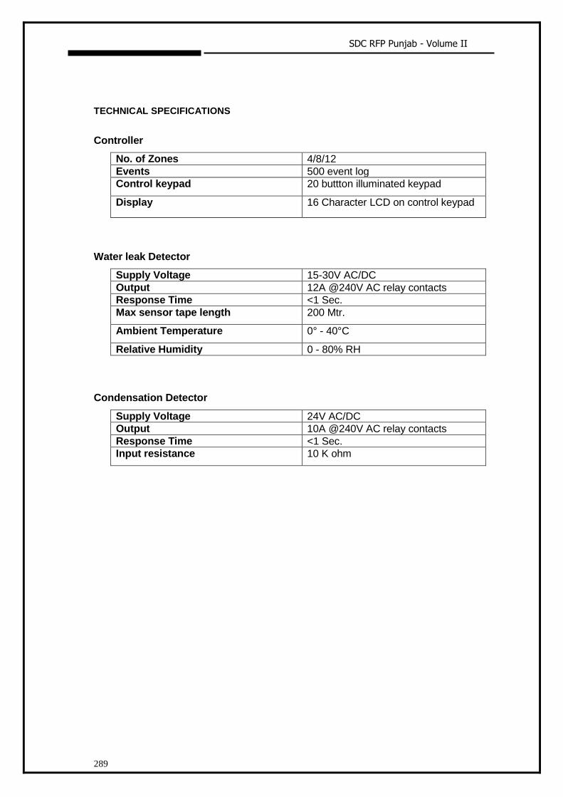
SDC RFP Punjab - Volume II
289
TECHNICAL SPECIFICATIONS
Controller
No. of Zones 4/8/12
Events 500 event log
Control keypad 20 buttton illuminated keypad
Display 16 Character LCD on control keypad
Water leak Detector
Supply Voltage 15-30V AC/DC
Output 12A @240V AC relay contacts
Response Time <1 Sec.
Max sensor tape length 200 Mtr.
Ambient Temperature 0° - 40°C
Relative Humidity 0 - 80% RH
Condensation Detector
Supply Voltage 24V AC/DC
Output 10A @240V AC relay contacts
Response Time <1 Sec.
Input resistance 10 K ohm
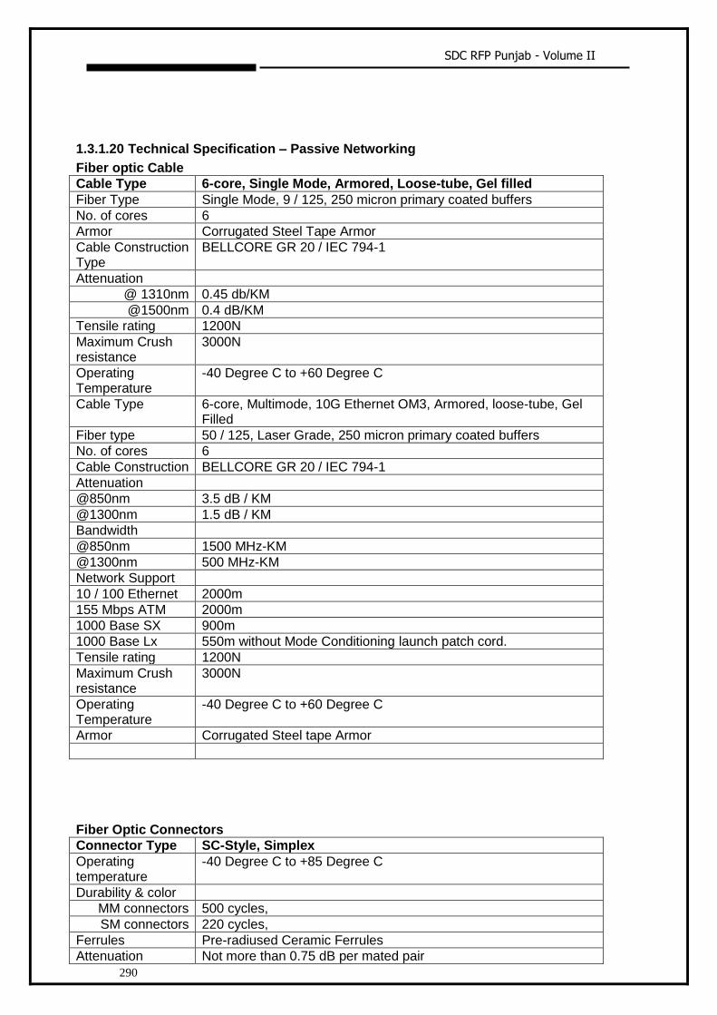
SDC RFP Punjab - Volume II
290
1.3.1.20 Technical Specification – Passive Networking
Fiber optic Cable
Cable Type 6-core, Single Mode, Armored, Loose-tube, Gel filled
Fiber Type Single Mode, 9 / 125, 250 micron primary coated buffers
No. of cores 6
Armor Corrugated Steel Tape Armor
Cable Construction Type
BELLCORE GR 20 / IEC 794-1
Attenuation
@ 1310nm 0.45 db/KM
@1500nm 0.4 dB/KM
Tensile rating 1200N
Maximum Crush resistance
3000N
Operating Temperature
-40 Degree C to +60 Degree C
Cable Type 6-core, Multimode, 10G Ethernet OM3, Armored, loose-tube, Gel Filled
Fiber type 50 / 125, Laser Grade, 250 micron primary coated buffers
No. of cores 6
Cable Construction BELLCORE GR 20 / IEC 794-1
Attenuation
@850nm 3.5 dB / KM
@1300nm 1.5 dB / KM
Bandwidth
@850nm 1500 MHz-KM
@1300nm 500 MHz-KM
Network Support
10 / 100 Ethernet 2000m
155 Mbps ATM 2000m
1000 Base SX 900m
1000 Base Lx 550m without Mode Conditioning launch patch cord.
Tensile rating 1200N
Maximum Crush resistance
3000N
Operating Temperature
-40 Degree C to +60 Degree C
Armor Corrugated Steel tape Armor
Fiber Optic Connectors
Connector Type SC-Style, Simplex
Operating temperature
-40 Degree C to +85 Degree C
Durability & color
MM connectors 500 cycles,
SM connectors 220 cycles,
Ferrules Pre-radiused Ceramic Ferrules
Attenuation Not more than 0.75 dB per mated pair
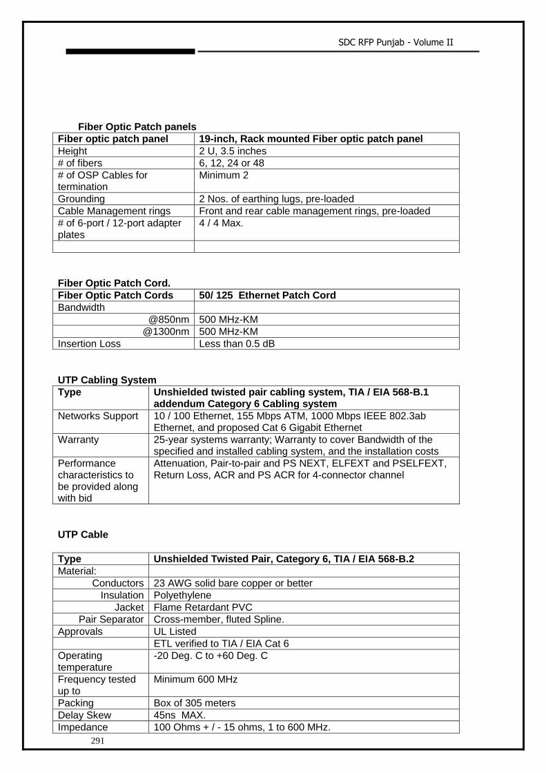
SDC RFP Punjab - Volume II
291
Fiber Optic Patch panels
Fiber optic patch panel 19-inch, Rack mounted Fiber optic patch panel
Height 2 U, 3.5 inches
# of fibers 6, 12, 24 or 48
# of OSP Cables for termination
Minimum 2
Grounding 2 Nos. of earthing lugs, pre-loaded
Cable Management rings Front and rear cable management rings, pre-loaded
# of 6-port / 12-port adapter plates
4 / 4 Max.
Fiber Optic Patch Cord.
Fiber Optic Patch Cords 50/ 125 Ethernet Patch Cord
Bandwidth
@850nm 500 MHz-KM
@1300nm 500 MHz-KM
Insertion Loss Less than 0.5 dB
UTP Cabling System
Type Unshielded twisted pair cabling system, TIA / EIA 568-B.1 addendum Category 6 Cabling system
Networks Support 10 / 100 Ethernet, 155 Mbps ATM, 1000 Mbps IEEE 802.3ab Ethernet, and proposed Cat 6 Gigabit Ethernet
Warranty 25-year systems warranty; Warranty to cover Bandwidth of the specified and installed cabling system, and the installation costs
Performance characteristics to be provided along with bid
Attenuation, Pair-to-pair and PS NEXT, ELFEXT and PSELFEXT, Return Loss, ACR and PS ACR for 4-connector channel
UTP Cable
Type Unshielded Twisted Pair, Category 6, TIA / EIA 568-B.2
Material:
Conductors 23 AWG solid bare copper or better
Insulation Polyethylene
Jacket Flame Retardant PVC
Pair Separator Cross-member, fluted Spline.
Approvals UL Listed
ETL verified to TIA / EIA Cat 6
Operating temperature
-20 Deg. C to +60 Deg. C
Frequency tested up to
Minimum 600 MHz
Packing Box of 305 meters
Delay Skew 45ns MAX.
Impedance 100 Ohms + / - 15 ohms, 1 to 600 MHz.
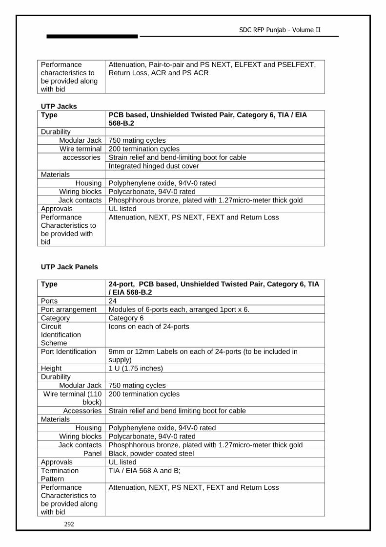
SDC RFP Punjab - Volume II
292
Performance characteristics to be provided along with bid
Attenuation, Pair-to-pair and PS NEXT, ELFEXT and PSELFEXT, Return Loss, ACR and PS ACR
UTP Jacks
Type PCB based, Unshielded Twisted Pair, Category 6, TIA / EIA 568-B.2
Durability
Modular Jack 750 mating cycles
Wire terminal 200 termination cycles
accessories Strain relief and bend-limiting boot for cable
Integrated hinged dust cover
Materials
Housing Polyphenylene oxide, 94V-0 rated
Wiring blocks Polycarbonate, 94V-0 rated
Jack contacts Phosphhorous bronze, plated with 1.27micro-meter thick gold
Approvals UL listed
Performance Characteristics to be provided with bid
Attenuation, NEXT, PS NEXT, FEXT and Return Loss
UTP Jack Panels
Type 24-port, PCB based, Unshielded Twisted Pair, Category 6, TIA
/ EIA 568-B.2
Ports 24
Port arrangement Modules of 6-ports each, arranged 1port x 6.
Category Category 6
Circuit Identification Scheme
Icons on each of 24-ports
Port Identification 9mm or 12mm Labels on each of 24-ports (to be included in supply)
Height 1 U (1.75 inches)
Durability
Modular Jack 750 mating cycles
Wire terminal (110 block)
200 termination cycles
Accessories Strain relief and bend limiting boot for cable
Materials
Housing Polyphenylene oxide, 94V-0 rated
Wiring blocks Polycarbonate, 94V-0 rated
Jack contacts Phosphhorous bronze, plated with 1.27micro-meter thick gold
Panel Black, powder coated steel
Approvals UL listed
Termination Pattern
TIA / EIA 568 A and B;
Performance Characteristics to be provided along with bid
Attenuation, NEXT, PS NEXT, FEXT and Return Loss

SDC RFP Punjab - Volume II
293
Work station patch Cords
Type Unshielded Twisted Pair, Category 6, TIA / EIA 568-B.2
Conductor 24 AWG 7 / 32, stranded copper
Length 7-feet
Plug Protection Matching colored snag-less, elastomer polyolefin boot
Warranty 25-year component warranty
Category Category 5
Plug
Housing Clear polycarbonate
Terminals Phosphor Bronze, 50 micron gold plating over selected area and gold flash over remainder, over 100 micron nickel underplate
Load bar PBT polyester
Jacket PVC
Insulation Flame Retardant Polyethylene
FLOOR CONCENTRATION BOX (FCB) FOR RAISED FLOOR ACCESS The Floor Concentration Box (FCB) should be mounted under the raised floor and should
provide an easy access to the consolidation box for field cables and patching cables.
The FCB should provide for clamping mechanism to the raised floor so as to get securely
mounted to the access flooring without obstructing the air floor and the cooling system. The
consolidation box should be used for a racking neighborhood of 3 racks as a cluster. The FCB
Forms an inter-connect between work area cabling and horizontal feeder cables.
The FCB should be designed for use in 2 ft x 2 ft raised floor systems.
The consolidation box should accommodate a total of 4U (2U+2U) of standard 19-inch patch
panels, Fiber Cassettes and/or cable management panels.
It should comply with NEC 300-22 (c) requirements for use in environmental air spaces.
If need arises the FCB should allow moves, adds and changes without re-terminating and re-
testing cables as well as routing of the patch cables.
The FCB design should comply with TIA/EIA-568-B and ISO 11801 requirements
Installation and Acceptance Testing Specifications Installed UTP Cabling System shall be tested with TIA / EIA 568 Level IIE / Level III hand held
testers. Each installed UTP drop shall be tested as per the latest revisions of TIA / EIA 568-B Cat
6 specifications. Length, Wire Map, Attenuation, Pair-to-pair and Power Sum NEXT, ELFEXT
and PS ELFEXT, Return Loss, Delay Skew, ACR and PS ACR shall be tested and results
provided to SIA in soft format on a CD.
Warranty Specifications: ITDA seeks warranty for the installed cable plant from the OEM equipment supplier. Bidder shall
ensure that the OEM norms for supply, installation, testing and documentation as specified by
the OEM supplier shall be adhered to, provided those are in line with TIA / EIA standards and

SDC RFP Punjab - Volume II
294
ITDA requirement specifications ( if any ). The warranty shall be provided by the OEM vendor to
ITDA and shall be administered in India. The duration of the system warranty shall be for a
minimum of 20 years and shall cover the system performance, application assurance and the
costs of the supply of components and installation. A Sample Warranty certificate shall be
provided by the bidder along with the bid.
Documentation Specifications: The successful bidder shall after completion of the installation, submit a detailed documentation
of the cable plant. The documentation shall cover, in the minimum, the following
i. As-built diagrams of the campus Network, with building and floor wise distribution
of users and connectivity
ii. Test results for UTP and Fiber links
iii. Consolidated BOM with manufacturer’s part Nos. and quantities used.
iv. Warranty certificate from OEM supplier
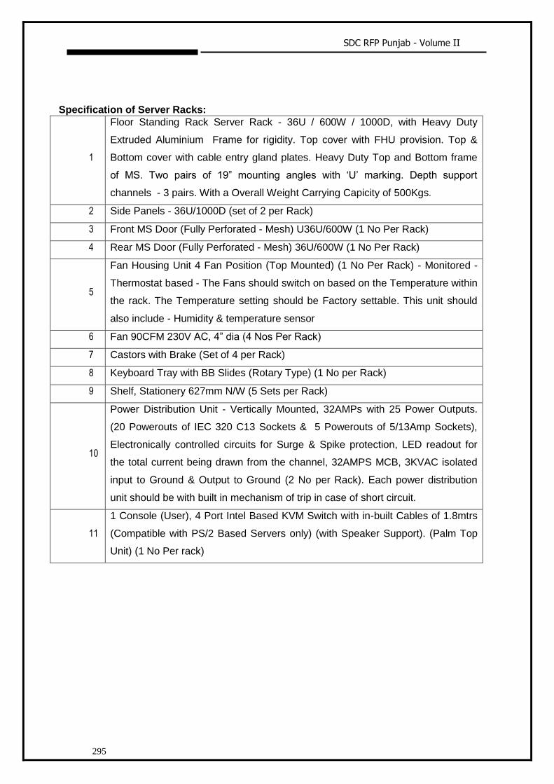
SDC RFP Punjab - Volume II
295
Specification of Server Racks:
1
Floor Standing Rack Server Rack - 36U / 600W / 1000D, with Heavy Duty
Extruded Aluminium Frame for rigidity. Top cover with FHU provision. Top &
Bottom cover with cable entry gland plates. Heavy Duty Top and Bottom frame
of MS. Two pairs of 19” mounting angles with ‘U’ marking. Depth support
channels - 3 pairs. With a Overall Weight Carrying Capicity of 500Kgs.
2 Side Panels - 36U/1000D (set of 2 per Rack)
3 Front MS Door (Fully Perforated - Mesh) U36U/600W (1 No Per Rack)
4 Rear MS Door (Fully Perforated - Mesh) 36U/600W (1 No Per Rack)
5
Fan Housing Unit 4 Fan Position (Top Mounted) (1 No Per Rack) - Monitored -
Thermostat based - The Fans should switch on based on the Temperature within
the rack. The Temperature setting should be Factory settable. This unit should
also include - Humidity & temperature sensor
6 Fan 90CFM 230V AC, 4” dia (4 Nos Per Rack)
7 Castors with Brake (Set of 4 per Rack)
8 Keyboard Tray with BB Slides (Rotary Type) (1 No per Rack)
9 Shelf, Stationery 627mm N/W (5 Sets per Rack)
10
Power Distribution Unit - Vertically Mounted, 32AMPs with 25 Power Outputs.
(20 Powerouts of IEC 320 C13 Sockets & 5 Powerouts of 5/13Amp Sockets),
Electronically controlled circuits for Surge & Spike protection, LED readout for
the total current being drawn from the channel, 32AMPS MCB, 3KVAC isolated
input to Ground & Output to Ground (2 No per Rack). Each power distribution
unit should be with built in mechanism of trip in case of short circuit.
11
1 Console (User), 4 Port Intel Based KVM Switch with in-built Cables of 1.8mtrs
(Compatible with PS/2 Based Servers only) (with Speaker Support). (Palm Top
Unit) (1 No Per rack)
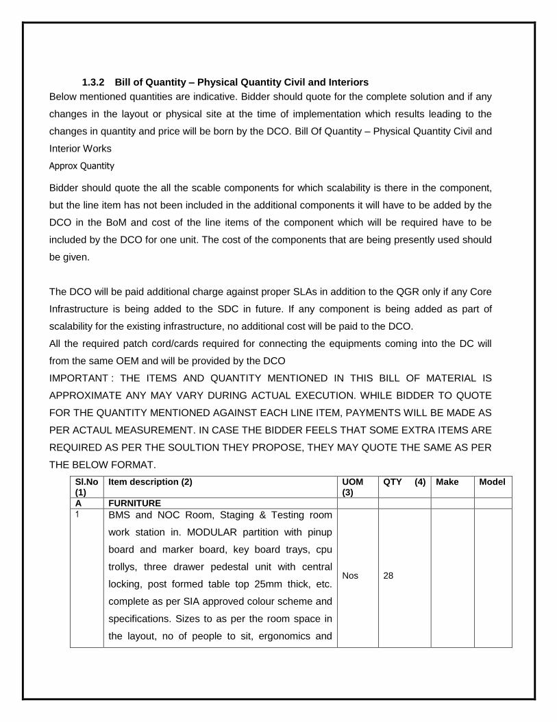
1.3.2 Bill of Quantity – Physical Quantity Civil and Interiors
Below mentioned quantities are indicative. Bidder should quote for the complete solution and if any
changes in the layout or physical site at the time of implementation which results leading to the
changes in quantity and price will be born by the DCO. Bill Of Quantity – Physical Quantity Civil and
Interior Works
Approx Quantity
Bidder should quote the all the scable components for which scalability is there in the component,
but the line item has not been included in the additional components it will have to be added by the
DCO in the BoM and cost of the line items of the component which will be required have to be
included by the DCO for one unit. The cost of the components that are being presently used should
be given.
The DCO will be paid additional charge against proper SLAs in addition to the QGR only if any Core
Infrastructure is being added to the SDC in future. If any component is being added as part of
scalability for the existing infrastructure, no additional cost will be paid to the DCO.
All the required patch cord/cards required for connecting the equipments coming into the DC will
from the same OEM and will be provided by the DCO
IMPORTANT : THE ITEMS AND QUANTITY MENTIONED IN THIS BILL OF MATERIAL IS
APPROXIMATE ANY MAY VARY DURING ACTUAL EXECUTION. WHILE BIDDER TO QUOTE
FOR THE QUANTITY MENTIONED AGAINST EACH LINE ITEM, PAYMENTS WILL BE MADE AS
PER ACTAUL MEASUREMENT. IN CASE THE BIDDER FEELS THAT SOME EXTRA ITEMS ARE
REQUIRED AS PER THE SOULTION THEY PROPOSE, THEY MAY QUOTE THE SAME AS PER
THE BELOW FORMAT.
Sl.No (1)
Item description (2) UOM (3)
QTY (4) Make Model
A FURNITURE
1 BMS and NOC Room, Staging & Testing room
work station in. MODULAR partition with pinup
board and marker board, key board trays, cpu
trollys, three drawer pedestal unit with central
locking, post formed table top 25mm thick, etc.
complete as per SIA approved colour scheme and
specifications. Sizes to as per the room space in
the layout, no of people to sit, ergonomics and
Nos 28
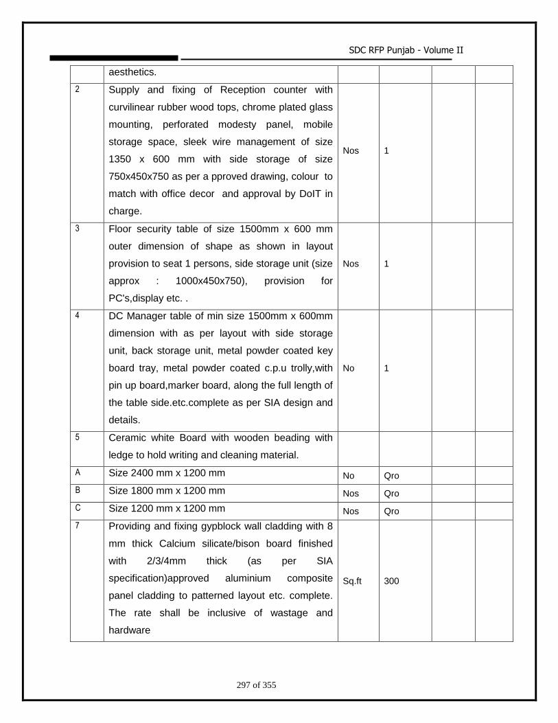
SDC RFP Punjab - Volume II
297 of 355
aesthetics.
2 Supply and fixing of Reception counter with
curvilinear rubber wood tops, chrome plated glass
mounting, perforated modesty panel, mobile
storage space, sleek wire management of size
1350 x 600 mm with side storage of size
750x450x750 as per a pproved drawing, colour to
match with office decor and approval by DoIT in
charge.
Nos 1
3 Floor security table of size 1500mm x 600 mm
outer dimension of shape as shown in layout
provision to seat 1 persons, side storage unit (size
approx : 1000x450x750), provision for
PC's,display etc. .
Nos 1
4 DC Manager table of min size 1500mm x 600mm
dimension with as per layout with side storage
unit, back storage unit, metal powder coated key
board tray, metal powder coated c.p.u trolly,with
pin up board,marker board, along the full length of
the table side.etc.complete as per SIA design and
details.
No 1
5 Ceramic white Board with wooden beading with
ledge to hold writing and cleaning material.
A Size 2400 mm x 1200 mm No Qro
B Size 1800 mm x 1200 mm Nos Qro
C Size 1200 mm x 1200 mm Nos Qro
7 Providing and fixing gypblock wall cladding with 8
mm thick Calcium silicate/bison board finished
with 2/3/4mm thick (as per SIA
specification)approved aluminium composite
panel cladding to patterned layout etc. complete.
The rate shall be inclusive of wastage and
hardware
Sq.ft 300
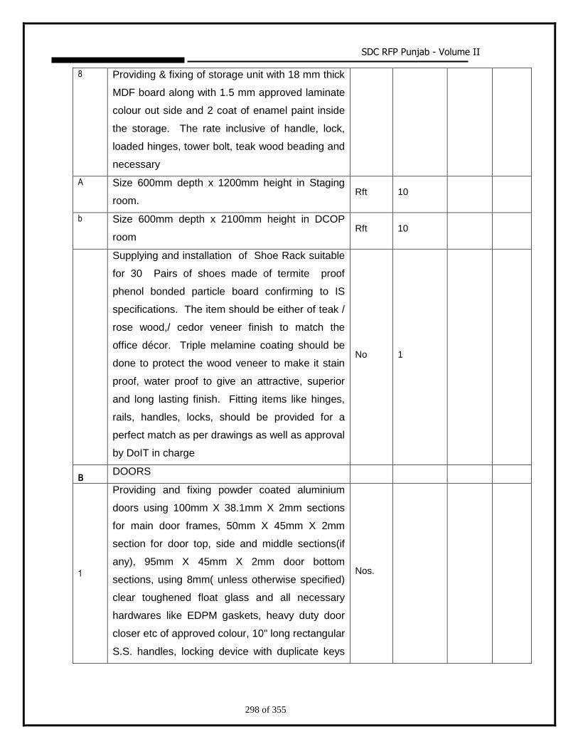
SDC RFP Punjab - Volume II
298 of 355
8 Providing & fixing of storage unit with 18 mm thick
MDF board along with 1.5 mm approved laminate
colour out side and 2 coat of enamel paint inside
the storage. The rate inclusive of handle, lock,
loaded hinges, tower bolt, teak wood beading and
necessary
A Size 600mm depth x 1200mm height in Staging
room. Rft 10
b Size 600mm depth x 2100mm height in DCOP
room Rft 10
Supplying and installation of Shoe Rack suitable
for 30 Pairs of shoes made of termite proof
phenol bonded particle board confirming to IS
specifications. The item should be either of teak /
rose wood,/ cedor veneer finish to match the
office décor. Triple melamine coating should be
done to protect the wood veneer to make it stain
proof, water proof to give an attractive, superior
and long lasting finish. Fitting items like hinges,
rails, handles, locks, should be provided for a
perfect match as per drawings as well as approval
by DoIT in charge
No 1
B DOORS
1
Providing and fixing powder coated aluminium
doors using 100mm X 38.1mm X 2mm sections
for main door frames, 50mm X 45mm X 2mm
section for door top, side and middle sections(if
any), 95mm X 45mm X 2mm door bottom
sections, using 8mm( unless otherwise specified)
clear toughened float glass and all necessary
hardwares like EDPM gaskets, heavy duty door
closer etc of approved colour, 10" long rectangular
S.S. handles, locking device with duplicate keys
Nos.
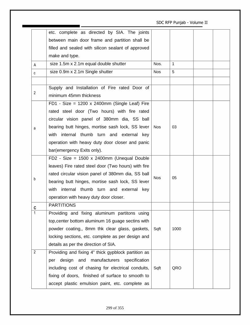
SDC RFP Punjab - Volume II
299 of 355
etc. complete as directed by SIA. The joints
between main door frame and partition shall be
filled and sealed with silicon sealant of approved
make and type.
A size 1.5m x 2.1m equal double shutter Nos. 1
c size 0.9m x 2.1m Single shutter Nos 5
2
Supply and Installation of Fire rated Door of
minimum 45mm thickness
a
FD1 - Size = 1200 x 2400mm (Single Leaf) Fire
rated steel door (Two hours) with fire rated
circular vision panel of 380mm dia, SS ball
bearing butt hinges, mortise sash lock, SS lever
with internal thumb turn and external key
operation with heavy duty door closer and panic
bar(emergency Exits only).
Nos 03
b
FD2 - Size = 1500 x 2400mm (Unequal Double
leaves) Fire rated steel door (Two hours) with fire
rated circular vision panel of 380mm dia, SS ball
bearing butt hinges, mortise sash lock, SS lever
with internal thumb turn and external key
operation with heavy duty door closer.
Nos 05
C PARTITIONS
1 Providing and fixing aluminum partitons using
top,center bottom aluminum 16 guage sectins with
powder coating,, 8mm thk clear glass, gaskets,
locking sections, etc. complete as per design and
details as per the direction of SIA.
Sqft 1000
2 Providing and fixing 4" thick gypblock partition as
per design and manufacturers specification
including cost of chasing for electrical conduits,
fixing of doors, finished of surface to smooth to
accept plastic emulsion paint, etc. complete as
Sqft QRO
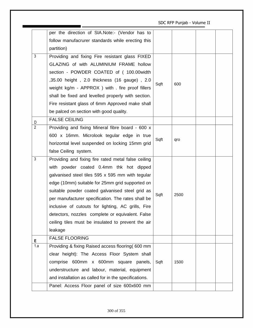
SDC RFP Punjab - Volume II
300 of 355
per the direction of SIA.Note:- (Vendor has to
follow manufacrurer standards while erecting this
partition)
3 Providing and fixing Fire resistant glass FIXED
GLAZING of with ALUMINIUM FRAME hollow
section - POWDER COATED of ( 100.00width
,35.00 height , 2.0 thickness (16 gauge) , 2.0
weight kg/m - APPROX ) with . fire proof fillers
shall be fixed and levelled properly with section.
Fire resistant glass of 6mm Approved make shall
be palced on section with good quality.
Sqft 600
D FALSE CEILING
2 Providing and fixing Mineral fibre board - 600 x
600 x 16mm. Microlook tegular edge in true
horizontal level suspended on locking 15mm grid
false Ceiling system.
Sqft qro
3 Providing and fixing fire rated metal false ceiling
with powder coated 0.4mm thk hot dipped
galvanised steel tiles 595 x 595 mm with tegular
edge (10mm) suitable for 25mm grid supported on
suitable powder coated galvanised steel grid as
per manufacturer specification. The rates shall be
inclusive of cutouts for lighting, AC grills, Fire
detectors, nozzles complete or equivalent. False
ceiling tiles must be insulated to prevent the air
leakage
Sqft 2500
E FALSE FLOORING
1.a Providing & fixing Raised access flooring( 600 mm
clear height): The Access Floor System shall
comprise 600mm x 600mm square panels,
understructure and labour, material, equipment
and installation as called for in the specifications.
Sqft 1500
Panel: Access Floor panel of size 600x600 mm
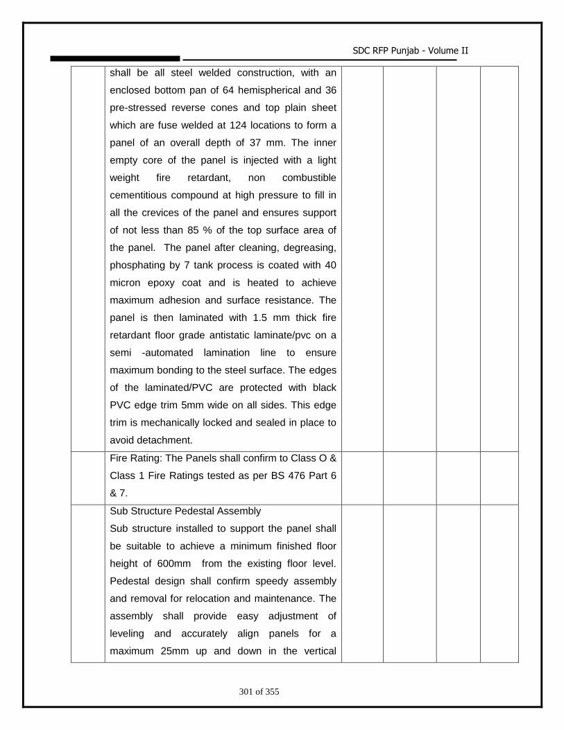
SDC RFP Punjab - Volume II
301 of 355
shall be all steel welded construction, with an
enclosed bottom pan of 64 hemispherical and 36
pre-stressed reverse cones and top plain sheet
which are fuse welded at 124 locations to form a
panel of an overall depth of 37 mm. The inner
empty core of the panel is injected with a light
weight fire retardant, non combustible
cementitious compound at high pressure to fill in
all the crevices of the panel and ensures support
of not less than 85 % of the top surface area of
the panel. The panel after cleaning, degreasing,
phosphating by 7 tank process is coated with 40
micron epoxy coat and is heated to achieve
maximum adhesion and surface resistance. The
panel is then laminated with 1.5 mm thick fire
retardant floor grade antistatic laminate/pvc on a
semi -automated lamination line to ensure
maximum bonding to the steel surface. The edges
of the laminated/PVC are protected with black
PVC edge trim 5mm wide on all sides. This edge
trim is mechanically locked and sealed in place to
avoid detachment.
Fire Rating: The Panels shall confirm to Class O &
Class 1 Fire Ratings tested as per BS 476 Part 6
& 7.
Sub Structure Pedestal Assembly
Sub structure installed to support the panel shall
be suitable to achieve a minimum finished floor
height of 600mm from the existing floor level.
Pedestal design shall confirm speedy assembly
and removal for relocation and maintenance. The
assembly shall provide easy adjustment of
leveling and accurately align panels for a
maximum 25mm up and down in the vertical
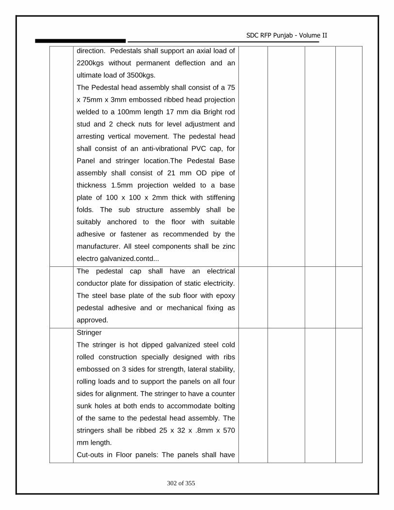
SDC RFP Punjab - Volume II
302 of 355
direction. Pedestals shall support an axial load of
2200kgs without permanent deflection and an
ultimate load of 3500kgs.
The Pedestal head assembly shall consist of a 75
x 75mm x 3mm embossed ribbed head projection
welded to a 100mm length 17 mm dia Bright rod
stud and 2 check nuts for level adjustment and
arresting vertical movement. The pedestal head
shall consist of an anti-vibrational PVC cap, for
Panel and stringer location.The Pedestal Base
assembly shall consist of 21 mm OD pipe of
thickness 1.5mm projection welded to a base
plate of 100 x 100 x 2mm thick with stiffening
folds. The sub structure assembly shall be
suitably anchored to the floor with suitable
adhesive or fastener as recommended by the
manufacturer. All steel components shall be zinc
electro galvanized.contd...
The pedestal cap shall have an electrical
conductor plate for dissipation of static electricity.
The steel base plate of the sub floor with epoxy
pedestal adhesive and or mechanical fixing as
approved.
Stringer
The stringer is hot dipped galvanized steel cold
rolled construction specially designed with ribs
embossed on 3 sides for strength, lateral stability,
rolling loads and to support the panels on all four
sides for alignment. The stringer to have a counter
sunk holes at both ends to accommodate bolting
of the same to the pedestal head assembly. The
stringers shall be ribbed 25 x 32 x .8mm x 570
mm length.
Cut-outs in Floor panels: The panels shall have
SDC RFP Punjab - Volume II
303 of 355
special cutouts as per the site
requirement:(Nos.18)
For electrical service outlet managers for cable
entry as required to be provided with a 50mm /
75mm grommet.
Lifting devices: Providing approved panel lifting
suction devices for lifting the floor panels.(Nos.4)
Glazed Panels: Providing and fixing of heavy duty
12mmthk. Toughened glass fixed in powder
coated Al. frame of size 1'x1' Glazed Floor Panels
with frame details same as above.(Nos.12)
Note: No extra cost will be included for above
items Perforated panel area shall be deducted &
paid in items E.1.1. The false flooring has to meet
the spec. as mentioned in the Technical
specification part of the RFP
b Same as above with 600 x 600 mm floor grills
made out of steel section to take a 4.5
Kn/25sqmm concentrated load(point) without
outlet aluminium volume control damper. The final
finish of the floor grills shall be the same in look
and feel as the floor tiles with antistatic tiles. It
shall be with 56% perforations of the surface area
of the tile to allow smooth air draft.
Nos 45
c Supply & Fixing of Antistatic Laminate skirting
matching with floor tiles with 8mm thick MDF
Board upto a height of 100mm.
Rft qro
2 Providing and laying Vitrified polished tile 2'0" x
2'0" in size flooring to floor pattern of approved
quality, approved colours and make, using
chemical tile adhesive laid to proper level and
joints pointed with tile jointing compound of
approved make including curing, finish and
cleaning etc. complete as directed by the SIA. The
Sqft 500
SDC RFP Punjab - Volume II
304 of 355
measurements shall be based on laid area of floor
and no extra payment shall be paid for wastage.
The rates shall include cost of laying protective
PVC sheets & POP which shall keep the floor
covered at all times till handing over of the site
etc. complete.
4 Same as above skirting upto a height of 4". Rft 300
5 Providing and fixing 9 mm thick Armaflex floor
insulation below the false flooring / above false
ceiling and joints should be finished properly with
adhesive tape as per manufacturer's specification.
The rate shall be inclusive of jointing tap, cleaning
the surface to make it free from dust.
Sqft 3000
F PAINTING
1 Providing and applying acrylic plastic emulsion
paint of approved make and shade to give an
even shade over a primer coat as per
manufacturers’ recommendations after applying
painting putty to level and plumb and finishing with
3 coats of plastic emulsion. Base coating shall
be as per manufacturer’s recommendation for
coverage of paint.
a For Ceiling Sqft 500
b For all vertical Plain surface Sqft 4000
c For all vertical surfaces with Approved Texture
Finish of approved pattern made using masking
tape in non-texture areas and later removing the
tape and finishing with plastic emulsion paint.
Sqft Qro
d Same as above with design texture finished with
plastic emulaion paint. Sqft Qro
2 Providing and laying POP punning over cement
plaster in perfect line and level with thickness of
10 - 12 mm including making good chases,
Sqft 2000
SDC RFP Punjab - Volume II
305 of 355
grooves, edge banding, scaffolding pockets etc.
complete as per directions of SIA.
3 Providing and applying Epoxy Paint for floor area
of approved make and shade over a coat of
primer and finishing with two coats of epoxy
paints. The overall thickness not less than 320
microns.
Sqft 1000
4 Providing and applying weather coat emulsion
paint of approved make and shade to give an
even shade over a primer coat as per
manufacturer’s recommendations after applying
painting putty to level and plumb and finishing with
2 coats of weather coat emulsion. Base coating
shall be as per manufacturer’s recommendation
for coverage of paint.
Sqft Qro
G MISCELLANEOUS
1 Providing and fixing Antistatic laminate with 25
mm Bison board steps and ramp based on vertical
surfaces of raised floors with complete all respect.
The rate shall be inclusive of 2.0mm thick
Antistatic laminate and hardwares etc.,
Sqft 75
2 Providing and fixing of 50mm Venetian blinds for
windows / fixed glazing, etc. as per standard
manufacturer specifications of approved colour
etc. as directed by the SIA. The number of
sections and its movement controls shall be
decided based on site conditions.
Sqft 150
3 Providing and fixing 100mm ledge with 12 mm
thick bison board with antistatic laminate finish
fixed in the gypblock partition to match with the
floor colour as directed by SIA.
Rft 300
4 Providing and fixing antiskid 3 M tape in the ramp
at 6" intervals of approved colour and make as Rft 180
SDC RFP Punjab - Volume II
306 of 355
directed by the SIA.
5 Providing and fixing of 3 M "Etching Film" in door /
windows as per approved shade and make etc. as
per the drawing and as directed by the SIA.
Sqft Qro
6 Providing and fixing of "Sun Control Film" in door
/ windows as per approved shade and make etc.
as per the drawing and as directed by the SIA.
Sqft Qro
7 Demolishing the existing brick wall with plastering.
The rate shall be inclusive of removing, cleaning
and disposing off the existing materials etc.
complete.
Cu.m 20
8 Providing and fixing 3M floor mat with approved
make and colours near the entrance door as
directed by SIA.
Sqft Qro
9 Providing and laying 230 mm thick brick work in
cement mortar of 1:4 (1 cement : 4 sand) with
bricks of approved quality chamber bricks of
class designation 50 and having crushing strength
not less than 50 Kg/Sft. Brick work shall be done
in such a way that all joints are full of mortar. The
thickness of joints shall not exceed 10 mm for
brick work. All the face joints shall be raked to a
minimum depth of 15 mm by raking tool during the
progress of brick work. The rate shall be includes
of mixing, scaffolding, raking of joints, curing etc.
Sqft Qro
10 Providing and laying 115 mm thick brick work in
cement mortar of 1:4 (1 cement : 4 sand) with
bricks of approved quality chamber bricks of
class designation 50 and having crushing strength
not less than 50 Kg/Sft. Brick work shall be done
in such a way that all joints are full of mortar. The
thickness of joints shall not exceed 10 mm for
brick work. All the face joints shall be raked to a
Sqft Qro
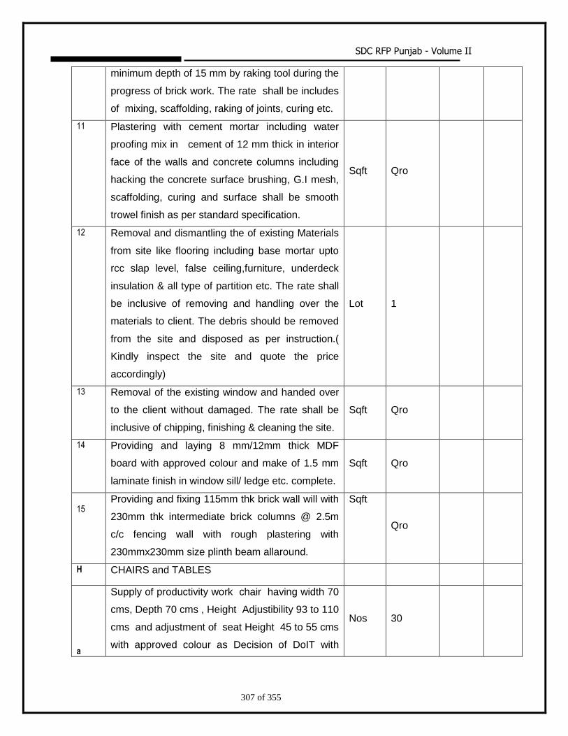
SDC RFP Punjab - Volume II
307 of 355
minimum depth of 15 mm by raking tool during the
progress of brick work. The rate shall be includes
of mixing, scaffolding, raking of joints, curing etc.
11 Plastering with cement mortar including water
proofing mix in cement of 12 mm thick in interior
face of the walls and concrete columns including
hacking the concrete surface brushing, G.I mesh,
scaffolding, curing and surface shall be smooth
trowel finish as per standard specification.
Sqft Qro
12 Removal and dismantling the of existing Materials
from site like flooring including base mortar upto
rcc slap level, false ceiling,furniture, underdeck
insulation & all type of partition etc. The rate shall
be inclusive of removing and handling over the
materials to client. The debris should be removed
from the site and disposed as per instruction.(
Kindly inspect the site and quote the price
accordingly)
Lot 1
13 Removal of the existing window and handed over
to the client without damaged. The rate shall be
inclusive of chipping, finishing & cleaning the site.
Sqft Qro
14 Providing and laying 8 mm/12mm thick MDF
board with approved colour and make of 1.5 mm
laminate finish in window sill/ ledge etc. complete.
Sqft Qro
15
Providing and fixing 115mm thk brick wall will with
230mm thk intermediate brick columns @ 2.5m
c/c fencing wall with rough plastering with
230mmx230mm size plinth beam allaround.
Sqft
Qro
H
CHAIRS and TABLES
a
Supply of productivity work chair having width 70
cms, Depth 70 cms , Height Adjustibility 93 to 110
cms and adjustment of seat Height 45 to 55 cms
with approved colour as Decision of DoIT with
Nos 30
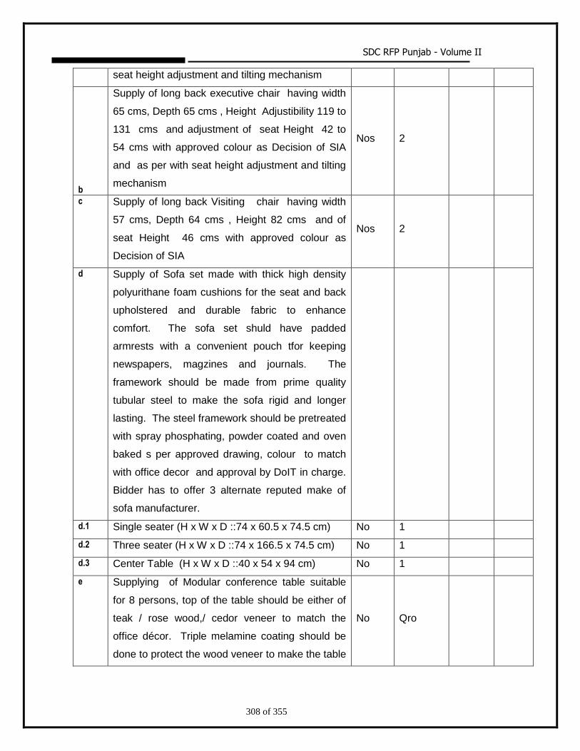
SDC RFP Punjab - Volume II
308 of 355
seat height adjustment and tilting mechanism
b
Supply of long back executive chair having width
65 cms, Depth 65 cms , Height Adjustibility 119 to
131 cms and adjustment of seat Height 42 to
54 cms with approved colour as Decision of SIA
and as per with seat height adjustment and tilting
mechanism
Nos 2
c Supply of long back Visiting chair having width
57 cms, Depth 64 cms , Height 82 cms and of
seat Height 46 cms with approved colour as
Decision of SIA
Nos 2
d Supply of Sofa set made with thick high density
polyurithane foam cushions for the seat and back
upholstered and durable fabric to enhance
comfort. The sofa set shuld have padded
armrests with a convenient pouch tfor keeping
newspapers, magzines and journals. The
framework should be made from prime quality
tubular steel to make the sofa rigid and longer
lasting. The steel framework should be pretreated
with spray phosphating, powder coated and oven
baked s per approved drawing, colour to match
with office decor and approval by DoIT in charge.
Bidder has to offer 3 alternate reputed make of
sofa manufacturer.
d.1 Single seater (H x W x D ::74 x 60.5 x 74.5 cm) No 1
d.2 Three seater (H x W x D ::74 x 166.5 x 74.5 cm) No 1
d.3 Center Table (H x W x D ::40 x 54 x 94 cm) No 1
e Supplying of Modular conference table suitable
for 8 persons, top of the table should be either of
teak / rose wood,/ cedor veneer to match the
office décor. Triple melamine coating should be
done to protect the wood veneer to make the table
No Qro

SDC RFP Punjab - Volume II
309 of 355
top stain proof, water proof to give an attractive,
superior and long lasting finish. Levelling screws
should be provided at the bottom of the legs for a
perfect balance on uneven flooring.
I Record protection equipment - Fire proof cabinets Nos 1
K Any other item required to make the
work/package complete
Bidder
to
specify
item
wise
Bidder to
specify
item wise
Note: All detailed specification and working drawing prior to the execution to be submitted by the bidder
Samples of all furniture items shall be got approved by SIA/Authorized Person prior to their supply &
installations.
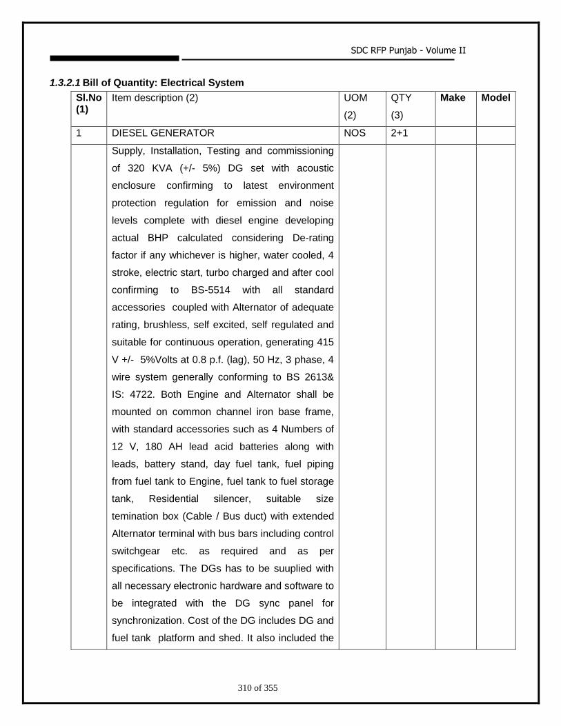
SDC RFP Punjab - Volume II
310 of 355
1.3.2.1 Bill of Quantity: Electrical System
Sl.No (1)
Item description (2) UOM
(2)
QTY
(3)
Make Model
1 DIESEL GENERATOR NOS 2+1
Supply, Installation, Testing and commissioning
of 320 KVA (+/- 5%) DG set with acoustic
enclosure confirming to latest environment
protection regulation for emission and noise
levels complete with diesel engine developing
actual BHP calculated considering De-rating
factor if any whichever is higher, water cooled, 4
stroke, electric start, turbo charged and after cool
confirming to BS-5514 with all standard
accessories coupled with Alternator of adequate
rating, brushless, self excited, self regulated and
suitable for continuous operation, generating 415
V +/- 5%Volts at 0.8 p.f. (lag), 50 Hz, 3 phase, 4
wire system generally conforming to BS 2613&
IS: 4722. Both Engine and Alternator shall be
mounted on common channel iron base frame,
with standard accessories such as 4 Numbers of
12 V, 180 AH lead acid batteries along with
leads, battery stand, day fuel tank, fuel piping
from fuel tank to Engine, fuel tank to fuel storage
tank, Residential silencer, suitable size
temination box (Cable / Bus duct) with extended
Alternator terminal with bus bars including control
switchgear etc. as required and as per
specifications. The DGs has to be suuplied with
all necessary electronic hardware and software to
be integrated with the DG sync panel for
synchronization. Cost of the DG includes DG and
fuel tank platform and shed. It also included the
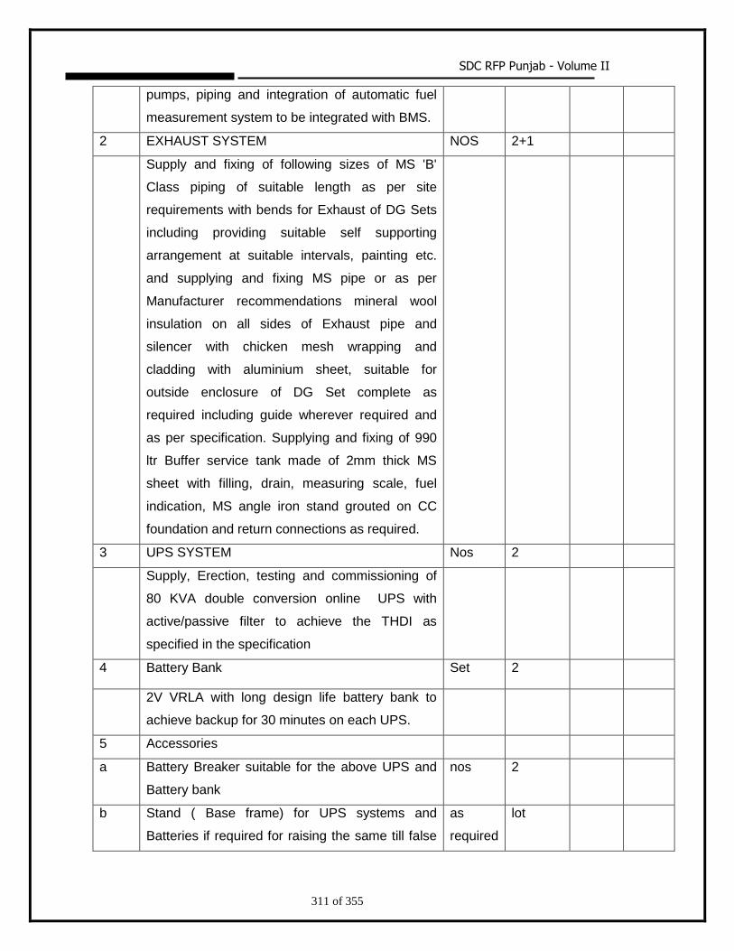
SDC RFP Punjab - Volume II
311 of 355
pumps, piping and integration of automatic fuel
measurement system to be integrated with BMS.
2 EXHAUST SYSTEM NOS 2+1
Supply and fixing of following sizes of MS 'B'
Class piping of suitable length as per site
requirements with bends for Exhaust of DG Sets
including providing suitable self supporting
arrangement at suitable intervals, painting etc.
and supplying and fixing MS pipe or as per
Manufacturer recommendations mineral wool
insulation on all sides of Exhaust pipe and
silencer with chicken mesh wrapping and
cladding with aluminium sheet, suitable for
outside enclosure of DG Set complete as
required including guide wherever required and
as per specification. Supplying and fixing of 990
ltr Buffer service tank made of 2mm thick MS
sheet with filling, drain, measuring scale, fuel
indication, MS angle iron stand grouted on CC
foundation and return connections as required.
3 UPS SYSTEM Nos 2
Supply, Erection, testing and commissioning of
80 KVA double conversion online UPS with
active/passive filter to achieve the THDI as
specified in the specification
4 Battery Bank Set 2
2V VRLA with long design life battery bank to
achieve backup for 30 minutes on each UPS.
5 Accessories
a Battery Breaker suitable for the above UPS and
Battery bank
nos 2
b Stand ( Base frame) for UPS systems and
Batteries if required for raising the same till false
as
required
lot
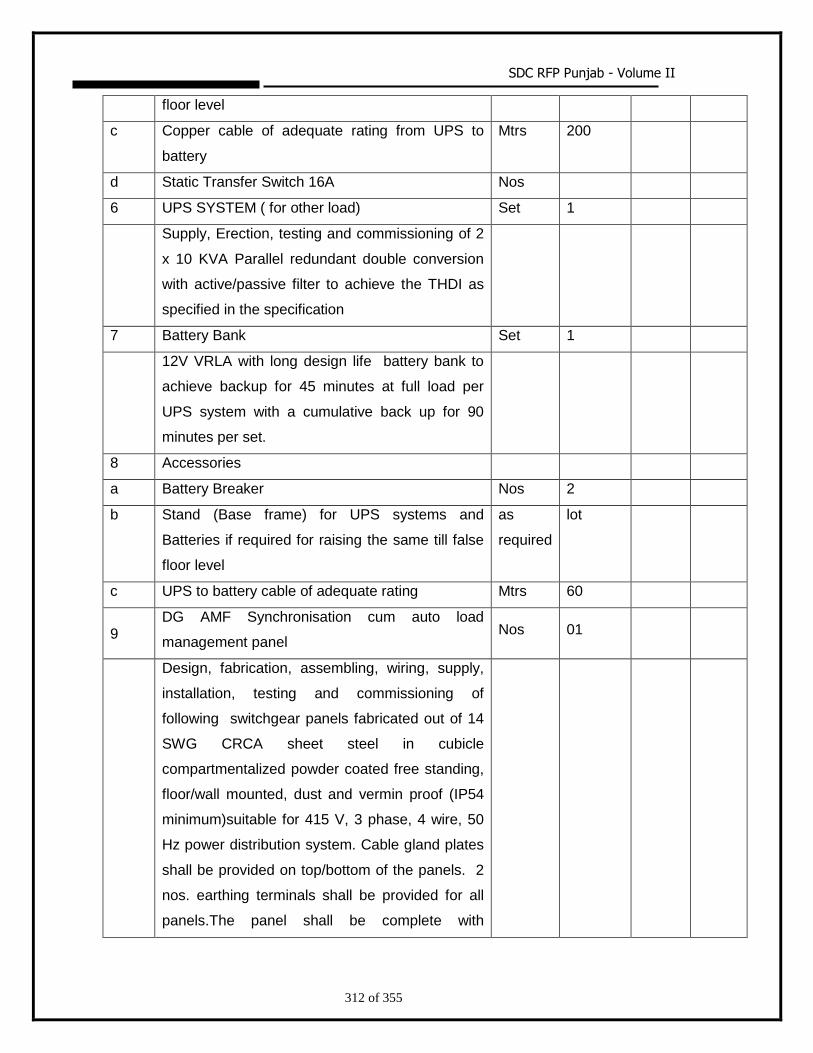
SDC RFP Punjab - Volume II
312 of 355
floor level
c Copper cable of adequate rating from UPS to
battery
Mtrs 200
d Static Transfer Switch 16A Nos
6 UPS SYSTEM ( for other load) Set 1
Supply, Erection, testing and commissioning of 2
x 10 KVA Parallel redundant double conversion
with active/passive filter to achieve the THDI as
specified in the specification
7 Battery Bank Set 1
12V VRLA with long design life battery bank to
achieve backup for 45 minutes at full load per
UPS system with a cumulative back up for 90
minutes per set.
8 Accessories
a Battery Breaker Nos 2
b Stand (Base frame) for UPS systems and
Batteries if required for raising the same till false
floor level
as
required
lot
c UPS to battery cable of adequate rating Mtrs 60
9 DG AMF Synchronisation cum auto load
management panel Nos 01
Design, fabrication, assembling, wiring, supply,
installation, testing and commissioning of
following switchgear panels fabricated out of 14
SWG CRCA sheet steel in cubicle
compartmentalized powder coated free standing,
floor/wall mounted, dust and vermin proof (IP54
minimum)suitable for 415 V, 3 phase, 4 wire, 50
Hz power distribution system. Cable gland plates
shall be provided on top/bottom of the panels. 2
nos. earthing terminals shall be provided for all
panels.The panel shall be complete with
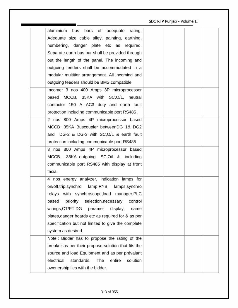
SDC RFP Punjab - Volume II
313 of 355
aluminium bus bars of adequate rating,
Adequate size cable alley, painting, earthing,
numbering, danger plate etc as required.
Separate earth bus bar shall be provided through
out the length of the panel. The incoming and
outgoing feeders shall be accommodated in a
modular multitier arrangement. All incoming and
outgoing feeders should be BMS compatible
Incomer 3 nos 400 Amps 3P microprocessor
based MCCB, 35KA with SC,O/L, neutral
contactor 150 A AC3 duty and earth fault
protection including communicable port RS485 .
2 nos 800 Amps 4P microprocessor based
MCCB ,35KA Buscoupler betweenDG 1& DG2
and DG-2 & DG-3 with SC,O/L & earth fault
protection including communicable port RS485
3 nos 800 Amps 4P microprocessor based
MCCB , 35KA outgoing SC,O/L & including
communicable port RS485 with display at front
facia.
4 nos energy analyzer, indication lamps for
on/off,trip,synchro lamp,RYB lamps,synchro
relays with synchroscope,load manager,PLC
based priority selection,necessary control
wirings,CT/PT,DG paramer display, name
plates,danger boards etc as required for & as per
specification but not limited to give the complete
system as desired.
Note : Bidder has to propose the rating of the
breaker as per their propose solution that fits the
source and load Equipment and as per prévalant
electrical standards. The entire solution
owenership lies with the bidder.
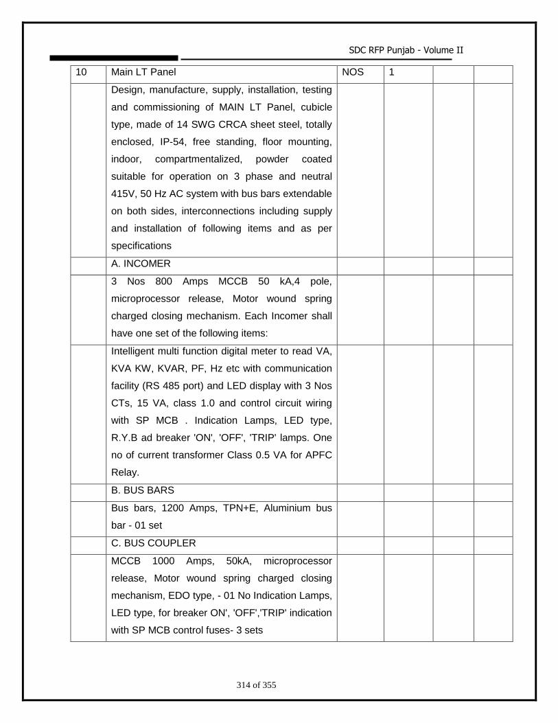
SDC RFP Punjab - Volume II
314 of 355
10 Main LT Panel NOS 1
Design, manufacture, supply, installation, testing
and commissioning of MAIN LT Panel, cubicle
type, made of 14 SWG CRCA sheet steel, totally
enclosed, IP-54, free standing, floor mounting,
indoor, compartmentalized, powder coated
suitable for operation on 3 phase and neutral
415V, 50 Hz AC system with bus bars extendable
on both sides, interconnections including supply
and installation of following items and as per
specifications
A. INCOMER
3 Nos 800 Amps MCCB 50 kA,4 pole,
microprocessor release, Motor wound spring
charged closing mechanism. Each Incomer shall
have one set of the following items:
Intelligent multi function digital meter to read VA,
KVA KW, KVAR, PF, Hz etc with communication
facility (RS 485 port) and LED display with 3 Nos
CTs, 15 VA, class 1.0 and control circuit wiring
with SP MCB . Indication Lamps, LED type,
R.Y.B ad breaker 'ON', 'OFF', 'TRIP' lamps. One
no of current transformer Class 0.5 VA for APFC
Relay.
B. BUS BARS
Bus bars, 1200 Amps, TPN+E, Aluminium bus
bar - 01 set
C. BUS COUPLER
MCCB 1000 Amps, 50kA, microprocessor
release, Motor wound spring charged closing
mechanism, EDO type, - 01 No Indication Lamps,
LED type, for breaker ON', 'OFF','TRIP' indication
with SP MCB control fuses- 3 sets
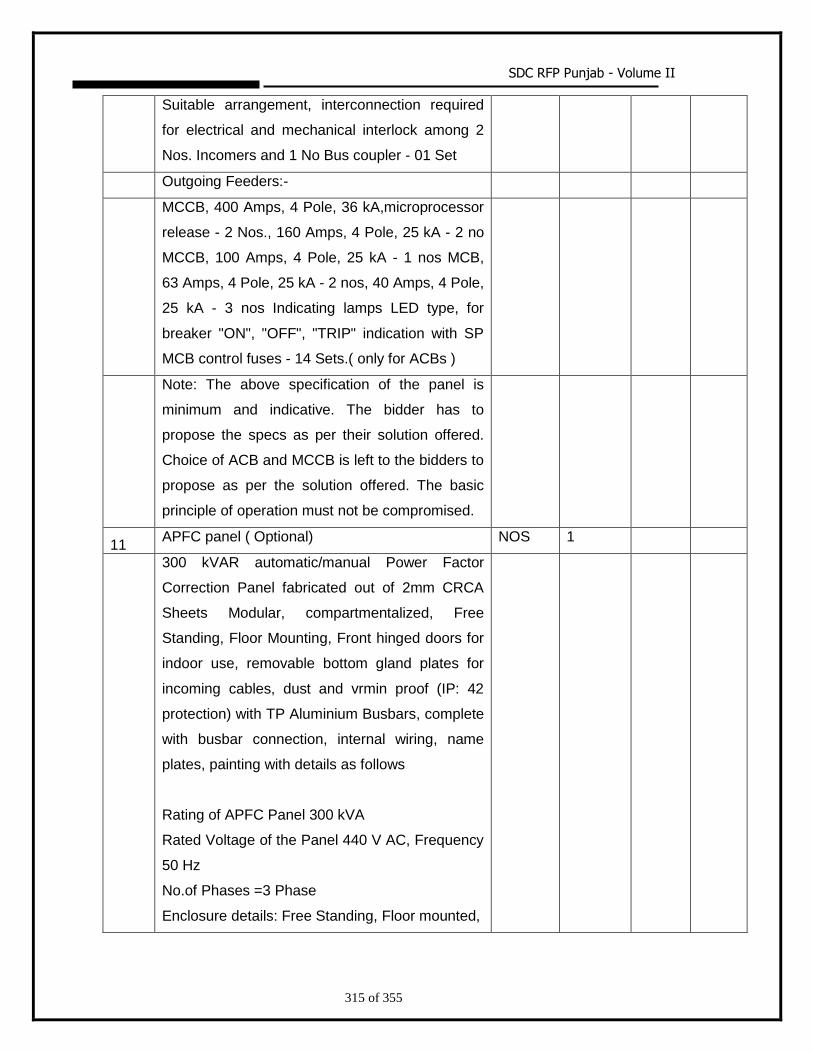
SDC RFP Punjab - Volume II
315 of 355
Suitable arrangement, interconnection required
for electrical and mechanical interlock among 2
Nos. Incomers and 1 No Bus coupler - 01 Set
Outgoing Feeders:-
MCCB, 400 Amps, 4 Pole, 36 kA,microprocessor
release - 2 Nos., 160 Amps, 4 Pole, 25 kA - 2 no
MCCB, 100 Amps, 4 Pole, 25 kA - 1 nos MCB,
63 Amps, 4 Pole, 25 kA - 2 nos, 40 Amps, 4 Pole,
25 kA - 3 nos Indicating lamps LED type, for
breaker "ON", "OFF", "TRIP" indication with SP
MCB control fuses - 14 Sets.( only for ACBs )
Note: The above specification of the panel is
minimum and indicative. The bidder has to
propose the specs as per their solution offered.
Choice of ACB and MCCB is left to the bidders to
propose as per the solution offered. The basic
principle of operation must not be compromised.
11 APFC panel ( Optional) NOS 1
300 kVAR automatic/manual Power Factor
Correction Panel fabricated out of 2mm CRCA
Sheets Modular, compartmentalized, Free
Standing, Floor Mounting, Front hinged doors for
indoor use, removable bottom gland plates for
incoming cables, dust and vrmin proof (IP: 42
protection) with TP Aluminium Busbars, complete
with busbar connection, internal wiring, name
plates, painting with details as follows
Rating of APFC Panel 300 kVA
Rated Voltage of the Panel 440 V AC, Frequency
50 Hz
No.of Phases =3 Phase
Enclosure details: Free Standing, Floor mounted,
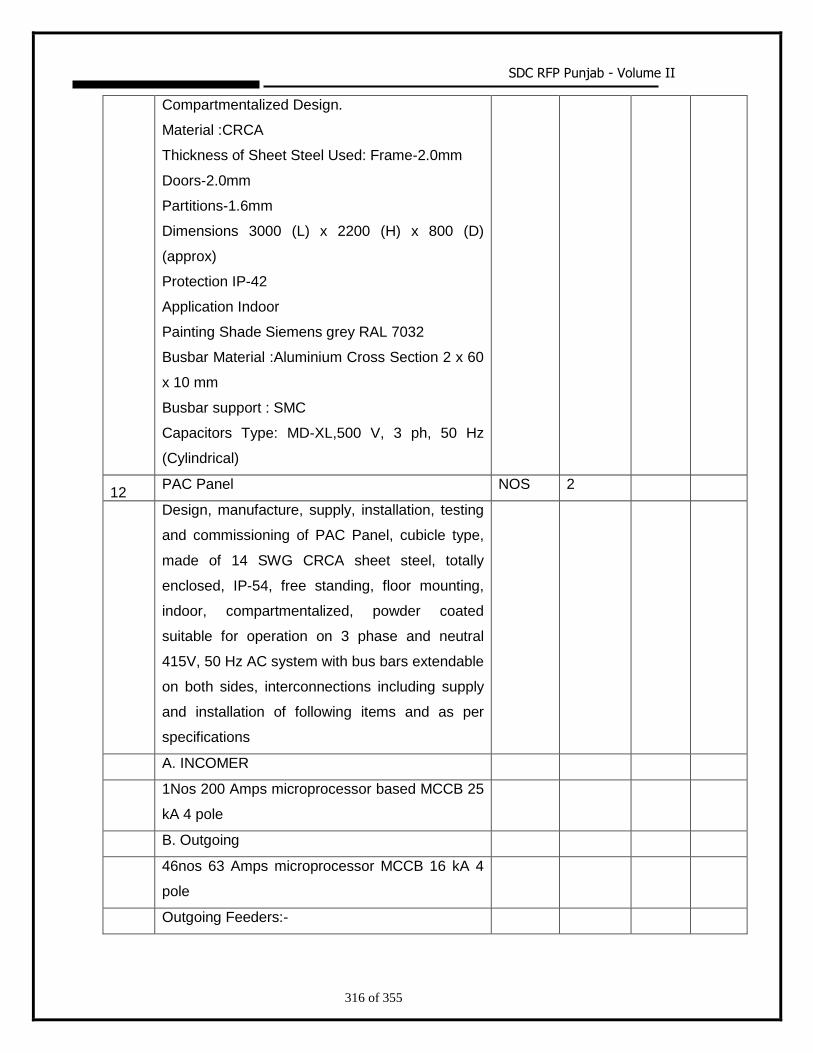
SDC RFP Punjab - Volume II
316 of 355
Compartmentalized Design.
Material :CRCA
Thickness of Sheet Steel Used: Frame-2.0mm
Doors-2.0mm
Partitions-1.6mm
Dimensions 3000 (L) x 2200 (H) x 800 (D)
(approx)
Protection IP-42
Application Indoor
Painting Shade Siemens grey RAL 7032
Busbar Material :Aluminium Cross Section 2 x 60
x 10 mm
Busbar support : SMC
Capacitors Type: MD-XL,500 V, 3 ph, 50 Hz
(Cylindrical)
12 PAC Panel NOS 2
Design, manufacture, supply, installation, testing
and commissioning of PAC Panel, cubicle type,
made of 14 SWG CRCA sheet steel, totally
enclosed, IP-54, free standing, floor mounting,
indoor, compartmentalized, powder coated
suitable for operation on 3 phase and neutral
415V, 50 Hz AC system with bus bars extendable
on both sides, interconnections including supply
and installation of following items and as per
specifications
A. INCOMER
1Nos 200 Amps microprocessor based MCCB 25
kA 4 pole
B. Outgoing
46nos 63 Amps microprocessor MCCB 16 kA 4
pole
Outgoing Feeders:-
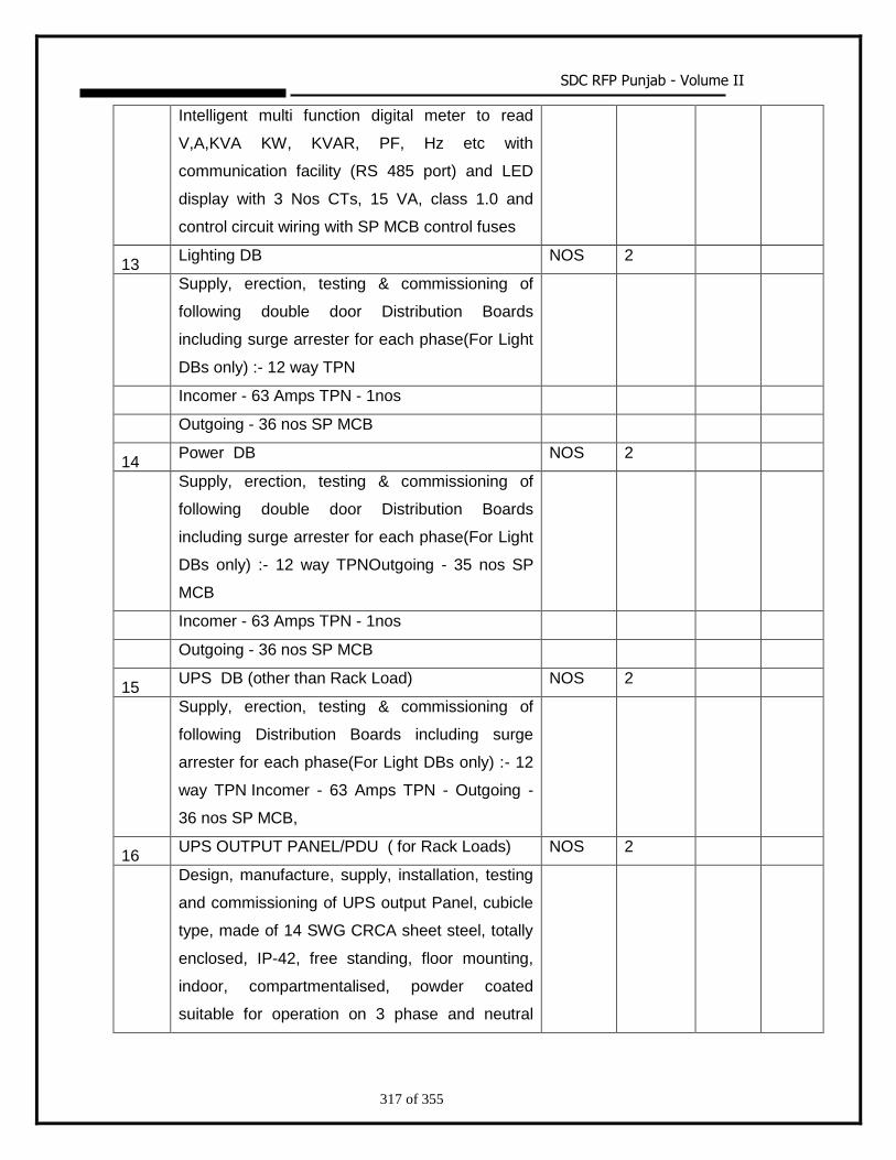
SDC RFP Punjab - Volume II
317 of 355
Intelligent multi function digital meter to read
V,A,KVA KW, KVAR, PF, Hz etc with
communication facility (RS 485 port) and LED
display with 3 Nos CTs, 15 VA, class 1.0 and
control circuit wiring with SP MCB control fuses
13 Lighting DB NOS 2
Supply, erection, testing & commissioning of
following double door Distribution Boards
including surge arrester for each phase(For Light
DBs only) :- 12 way TPN
Incomer - 63 Amps TPN - 1nos
Outgoing - 36 nos SP MCB
14 Power DB NOS 2
Supply, erection, testing & commissioning of
following double door Distribution Boards
including surge arrester for each phase(For Light
DBs only) :- 12 way TPNOutgoing - 35 nos SP
MCB
Incomer - 63 Amps TPN - 1nos
Outgoing - 36 nos SP MCB
15 UPS DB (other than Rack Load) NOS 2
Supply, erection, testing & commissioning of
following Distribution Boards including surge
arrester for each phase(For Light DBs only) :- 12
way TPN Incomer - 63 Amps TPN - Outgoing -
36 nos SP MCB,
16 UPS OUTPUT PANEL/PDU ( for Rack Loads) NOS 2
Design, manufacture, supply, installation, testing
and commissioning of UPS output Panel, cubicle
type, made of 14 SWG CRCA sheet steel, totally
enclosed, IP-42, free standing, floor mounting,
indoor, compartmentalised, powder coated
suitable for operation on 3 phase and neutral
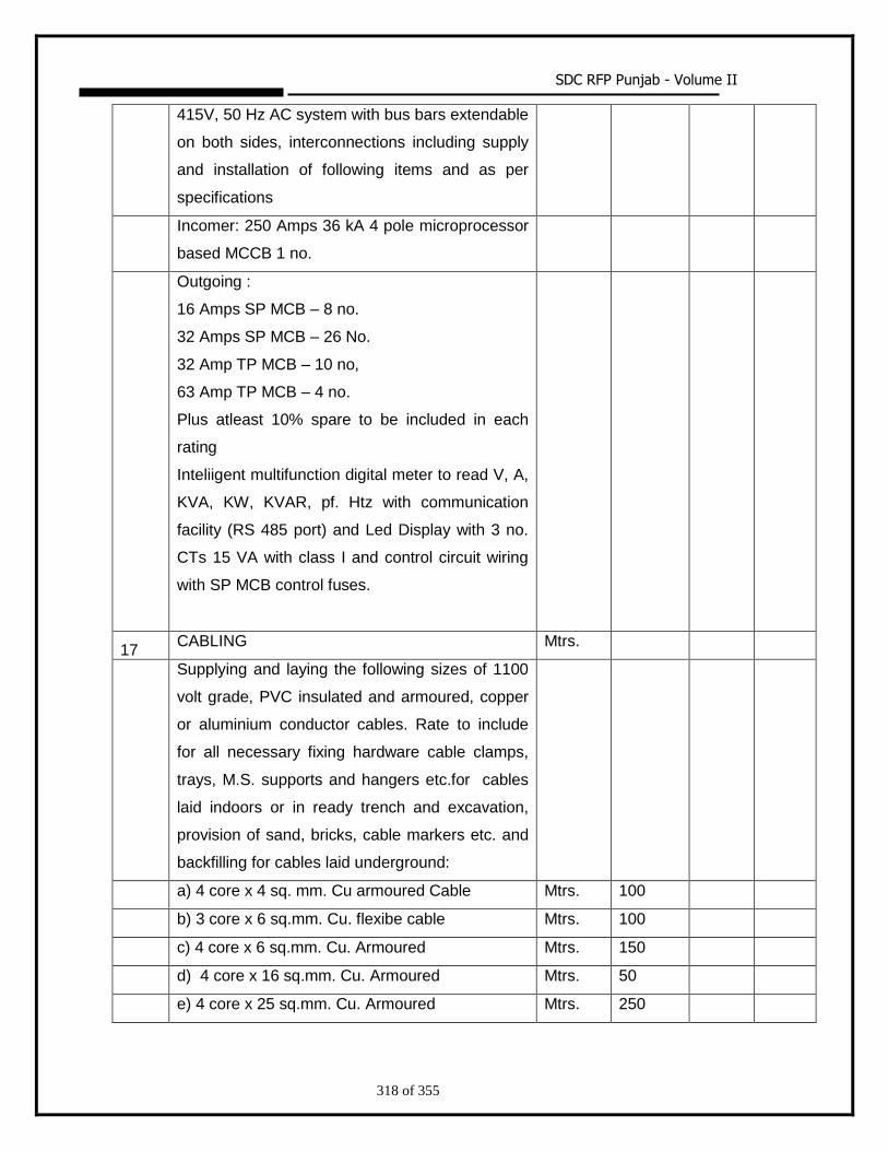
SDC RFP Punjab - Volume II
318 of 355
415V, 50 Hz AC system with bus bars extendable
on both sides, interconnections including supply
and installation of following items and as per
specifications
Incomer: 250 Amps 36 kA 4 pole microprocessor
based MCCB 1 no.
Outgoing :
16 Amps SP MCB – 8 no.
32 Amps SP MCB – 26 No.
32 Amp TP MCB – 10 no,
63 Amp TP MCB – 4 no.
Plus atleast 10% spare to be included in each
rating
Inteliigent multifunction digital meter to read V, A,
KVA, KW, KVAR, pf. Htz with communication
facility (RS 485 port) and Led Display with 3 no.
CTs 15 VA with class I and control circuit wiring
with SP MCB control fuses.
17 CABLING Mtrs.
Supplying and laying the following sizes of 1100
volt grade, PVC insulated and armoured, copper
or aluminium conductor cables. Rate to include
for all necessary fixing hardware cable clamps,
trays, M.S. supports and hangers etc.for cables
laid indoors or in ready trench and excavation,
provision of sand, bricks, cable markers etc. and
backfilling for cables laid underground:
a) 4 core x 4 sq. mm. Cu armoured Cable Mtrs. 100
b) 3 core x 6 sq.mm. Cu. flexibe cable Mtrs. 100
c) 4 core x 6 sq.mm. Cu. Armoured Mtrs. 150
d) 4 core x 16 sq.mm. Cu. Armoured Mtrs. 50
e) 4 core x 25 sq.mm. Cu. Armoured Mtrs. 250
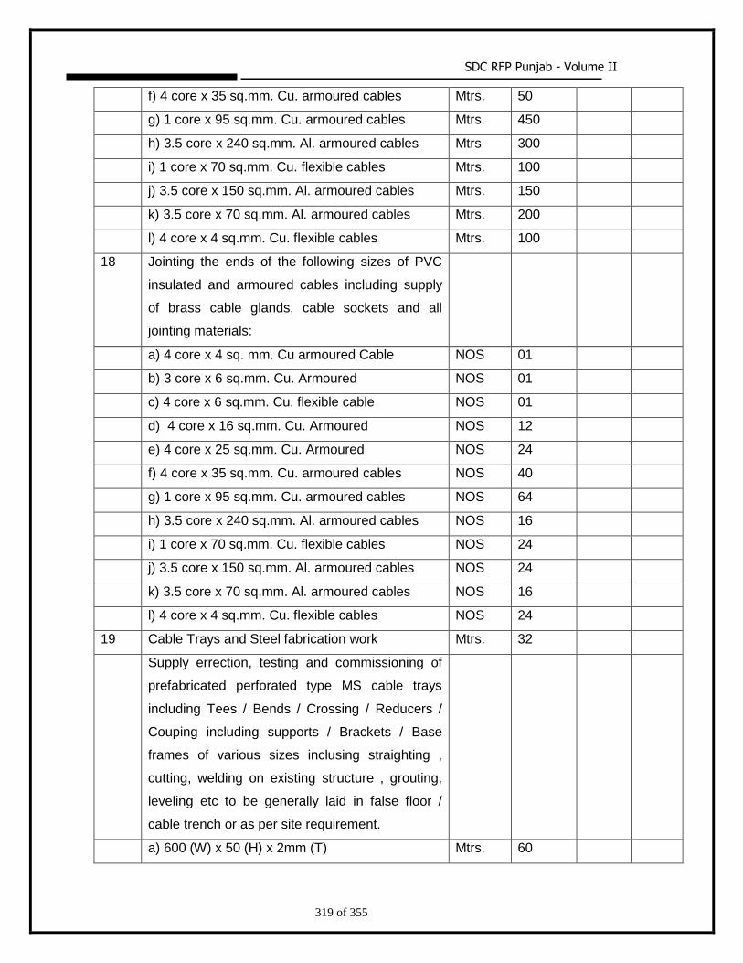
SDC RFP Punjab - Volume II
319 of 355
f) 4 core x 35 sq.mm. Cu. armoured cables Mtrs. 50
g) 1 core x 95 sq.mm. Cu. armoured cables Mtrs. 450
h) 3.5 core x 240 sq.mm. Al. armoured cables Mtrs 300
i) 1 core x 70 sq.mm. Cu. flexible cables Mtrs. 100
j) 3.5 core x 150 sq.mm. Al. armoured cables Mtrs. 150
k) 3.5 core x 70 sq.mm. Al. armoured cables Mtrs. 200
l) 4 core x 4 sq.mm. Cu. flexible cables Mtrs. 100
18 Jointing the ends of the following sizes of PVC
insulated and armoured cables including supply
of brass cable glands, cable sockets and all
jointing materials:
a) 4 core x 4 sq. mm. Cu armoured Cable NOS 01
b) 3 core x 6 sq.mm. Cu. Armoured NOS 01
c) 4 core x 6 sq.mm. Cu. flexible cable NOS 01
d) 4 core x 16 sq.mm. Cu. Armoured NOS 12
e) 4 core x 25 sq.mm. Cu. Armoured NOS 24
f) 4 core x 35 sq.mm. Cu. armoured cables NOS 40
g) 1 core x 95 sq.mm. Cu. armoured cables NOS 64
h) 3.5 core x 240 sq.mm. Al. armoured cables NOS 16
i) 1 core x 70 sq.mm. Cu. flexible cables NOS 24
j) 3.5 core x 150 sq.mm. Al. armoured cables NOS 24
k) 3.5 core x 70 sq.mm. Al. armoured cables NOS 16
l) 4 core x 4 sq.mm. Cu. flexible cables NOS 24
19 Cable Trays and Steel fabrication work Mtrs. 32
Supply errection, testing and commissioning of
prefabricated perforated type MS cable trays
including Tees / Bends / Crossing / Reducers /
Couping including supports / Brackets / Base
frames of various sizes inclusing straighting ,
cutting, welding on existing structure , grouting,
leveling etc to be generally laid in false floor /
cable trench or as per site requirement.
a) 600 (W) x 50 (H) x 2mm (T) Mtrs. 60
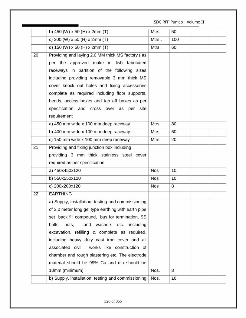
SDC RFP Punjab - Volume II
320 of 355
b) 450 (W) x 50 (H) x 2mm (T). Mtrs. 50
c) 300 (W) x 50 (H) x 2mm (T) Mtrs.. 100
d) 150 (W) x 50 (H) x 2mm (T) Mtrs. 60
20 Providing and laying 2.0 MM thick MS factory ( as
per the approved make in list) fabricated
raceways in partition of the following sizes
including providing removable 3 mm thick MS
cover knock out holes and fixing accessories
complete as required including floor supports,
bends, access boxes and tap off boxes as per
specification and cross over as per site
requirement
a) 450 mm wide x 100 mm deep raceway Mtrs 80
b) 400 mm wide x 100 mm deep raceway Mtrs 60
c) 150 mm wide x 100 mm deep raceway Mtrs 20
21 Providing and fixing junction box including
providing 3 mm thick stainless steel cover
required as per specification.
a) 450x450x120 Nos 10
b) 550x550x120 Nos 10
c) 200x200x120 Nos 8
22 EARTHING
a) Supply, installation, testing and commissioning
of 3.0 meter long gel type earthing with earth pipe
set back fill compound, bus for termination, SS
bolts, nuts, and washers etc. including
excavation, refilling & complete as required,
including heavy duty cast iron cover and all
associated civil works like construction of
chamber and rough plastering etc. The electrode
material should be 99% Cu and dia should be
10mm (minimum) Nos. 8
b) Supply, installation, testing and commissioning Nos. 16
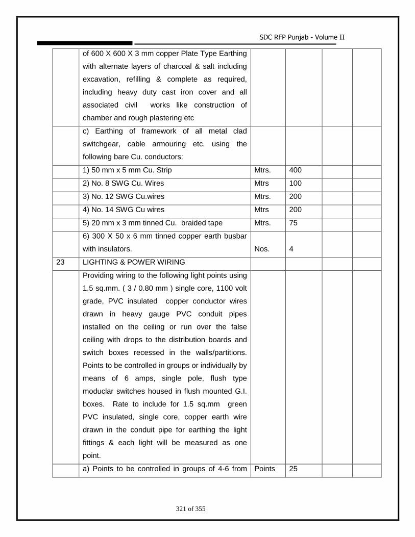
SDC RFP Punjab - Volume II
321 of 355
of 600 X 600 X 3 mm copper Plate Type Earthing
with alternate layers of charcoal & salt including
excavation, refilling & complete as required,
including heavy duty cast iron cover and all
associated civil works like construction of
chamber and rough plastering etc
c) Earthing of framework of all metal clad
switchgear, cable armouring etc. using the
following bare Cu. conductors:
1) 50 mm x 5 mm Cu. Strip Mtrs. 400
2) No. 8 SWG Cu. Wires Mtrs 100
3) No. 12 SWG Cu.wires Mtrs. 200
4) No. 14 SWG Cu wires Mtrs 200
5) 20 mm x 3 mm tinned Cu. braided tape Mtrs. 75
6) 300 X 50 x 6 mm tinned copper earth busbar
with insulators. Nos. 4
23 LIGHTING & POWER WIRING
Providing wiring to the following light points using
1.5 sq.mm. ( 3 / 0.80 mm ) single core, 1100 volt
grade, PVC insulated copper conductor wires
drawn in heavy gauge PVC conduit pipes
installed on the ceiling or run over the false
ceiling with drops to the distribution boards and
switch boxes recessed in the walls/partitions.
Points to be controlled in groups or individually by
means of 6 amps, single pole, flush type
moduclar switches housed in flush mounted G.I.
boxes. Rate to include for 1.5 sq.mm green
PVC insulated, single core, copper earth wire
drawn in the conduit pipe for earthing the light
fittings & each light will be measured as one
point.
a) Points to be controlled in groups of 4-6 from Points 25
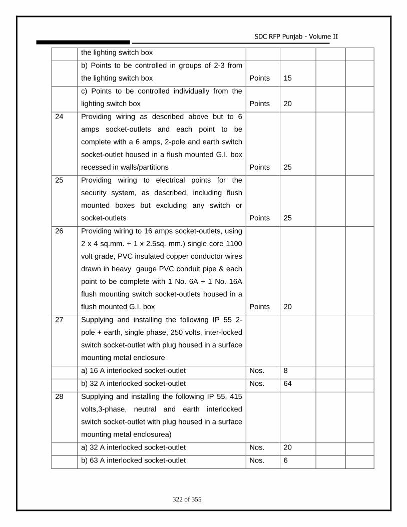
SDC RFP Punjab - Volume II
322 of 355
the lighting switch box
b) Points to be controlled in groups of 2-3 from
the lighting switch box Points 15
c) Points to be controlled individually from the
lighting switch box Points 20
24 Providing wiring as described above but to 6
amps socket-outlets and each point to be
complete with a 6 amps, 2-pole and earth switch
socket-outlet housed in a flush mounted G.I. box
recessed in walls/partitions Points 25
25 Providing wiring to electrical points for the
security system, as described, including flush
mounted boxes but excluding any switch or
socket-outlets Points 25
26 Providing wiring to 16 amps socket-outlets, using
2 x 4 sq.mm. + 1 x 2.5sq. mm.) single core 1100
volt grade, PVC insulated copper conductor wires
drawn in heavy gauge PVC conduit pipe & each
point to be complete with 1 No. 6A + 1 No. 16A
flush mounting switch socket-outlets housed in a
flush mounted G.I. box Points 20
27 Supplying and installing the following IP 55 2-
pole + earth, single phase, 250 volts, inter-locked
switch socket-outlet with plug housed in a surface
mounting metal enclosure
a) 16 A interlocked socket-outlet Nos. 8
b) 32 A interlocked socket-outlet Nos. 64
28 Supplying and installing the following IP 55, 415
volts,3-phase, neutral and earth interlocked
switch socket-outlet with plug housed in a surface
mounting metal enclosurea)
a) 32 A interlocked socket-outlet Nos. 20
b) 63 A interlocked socket-outlet Nos. 6
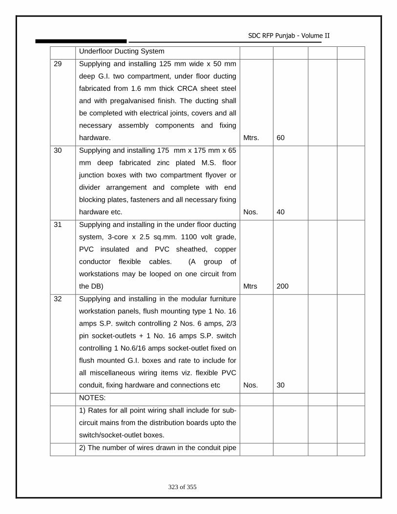
SDC RFP Punjab - Volume II
323 of 355
Underfloor Ducting System
29 Supplying and installing 125 mm wide x 50 mm
deep G.I. two compartment, under floor ducting
fabricated from 1.6 mm thick CRCA sheet steel
and with pregalvanised finish. The ducting shall
be completed with electrical joints, covers and all
necessary assembly components and fixing
hardware. Mtrs. 60
30 Supplying and installing 175 mm x 175 mm x 65
mm deep fabricated zinc plated M.S. floor
junction boxes with two compartment flyover or
divider arrangement and complete with end
blocking plates, fasteners and all necessary fixing
hardware etc. Nos. 40
31 Supplying and installing in the under floor ducting
system, 3-core x 2.5 sq.mm. 1100 volt grade,
PVC insulated and PVC sheathed, copper
conductor flexible cables. (A group of
workstations may be looped on one circuit from
the DB) Mtrs 200
32 Supplying and installing in the modular furniture
workstation panels, flush mounting type 1 No. 16
amps S.P. switch controlling 2 Nos. 6 amps, 2/3
pin socket-outlets + 1 No. 16 amps S.P. switch
controlling 1 No.6/16 amps socket-outlet fixed on
flush mounted G.I. boxes and rate to include for
all miscellaneous wiring items viz. flexible PVC
conduit, fixing hardware and connections etc Nos. 30
NOTES:
1) Rates for all point wiring shall include for sub-
circuit mains from the distribution boards upto the
switch/socket-outlet boxes.
2) The number of wires drawn in the conduit pipe
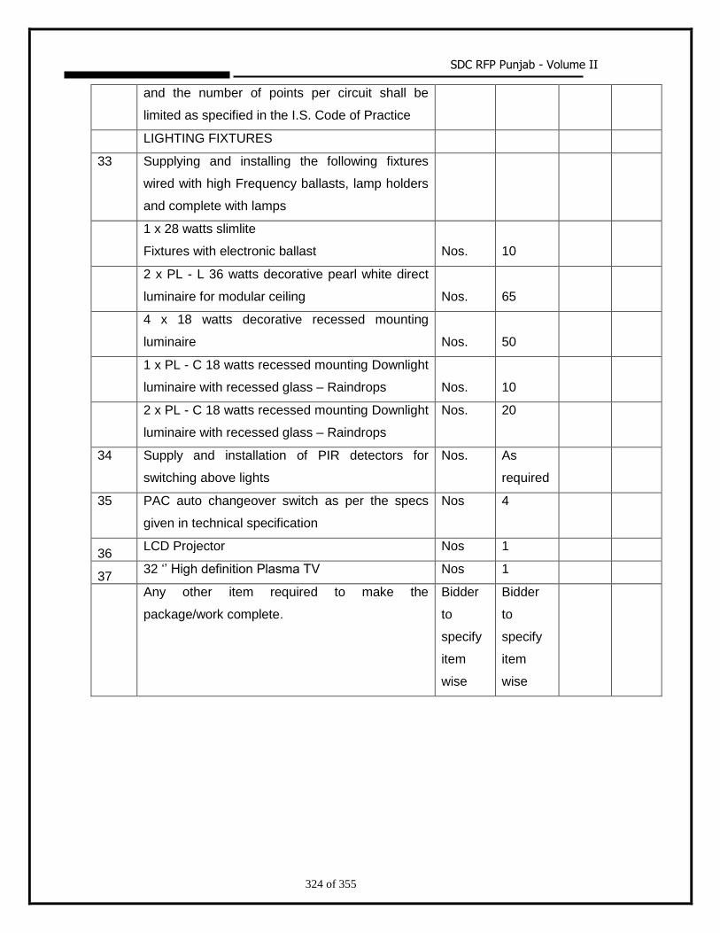
SDC RFP Punjab - Volume II
324 of 355
and the number of points per circuit shall be
limited as specified in the I.S. Code of Practice
LIGHTING FIXTURES
33 Supplying and installing the following fixtures
wired with high Frequency ballasts, lamp holders
and complete with lamps
1 x 28 watts slimlite
Fixtures with electronic ballast Nos. 10
2 x PL - L 36 watts decorative pearl white direct
luminaire for modular ceiling Nos. 65
4 x 18 watts decorative recessed mounting
luminaire Nos. 50
1 x PL - C 18 watts recessed mounting Downlight
luminaire with recessed glass – Raindrops Nos. 10
2 x PL - C 18 watts recessed mounting Downlight
luminaire with recessed glass – Raindrops
Nos. 20
34 Supply and installation of PIR detectors for
switching above lights
Nos. As
required
35 PAC auto changeover switch as per the specs
given in technical specification
Nos 4
36 LCD Projector Nos 1
37 32 ‘’ High definition Plasma TV Nos 1
Any other item required to make the
package/work complete.
Bidder
to
specify
item
wise
Bidder
to
specify
item
wise
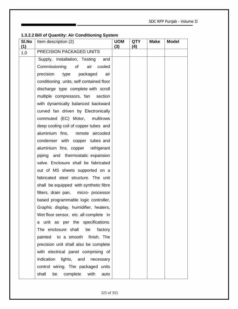
SDC RFP Punjab - Volume II
325 of 355
1.3.2.2 Bill of Quantity: Air Conditioning System
Sl.No (1)
Item description (2) UOM (3)
QTY (4)
Make Model
1.0 PRECISION PACKAGED UNITS
Supply, Installation, Testing and
Commissioning of air cooled
precision type packaged air
conditioning units, self contained floor
discharge type complete with scroll
multiple compressors, fan section
with dynamically balanced backward
curved fan driven by Electronically
commuted (EC) Motor, multirows
deep cooling coil of copper tubes and
aluminium fins, remote aircooled
condenser with copper tubes and
aluminium fins, copper refrigerant
piping and thermostatic expansion
valve. Enclosure shall be fabricated
out of MS sheets supported on a
fabricated steel structure. The unit
shall be equipped with synthetic fibre
filters, drain pan, micro- processor
based programmable logic controller,
Graphic display, humidifier, heaters,
Wet floor sensor, etc. all complete in
a unit as per the specifications.
The enclosure shall be factory
painted to a smooth finish. The
precision unit shall also be complete
with electrical panel comprising of
indication lights, and necessary
control wiring. The packaged units
shall be complete with auto
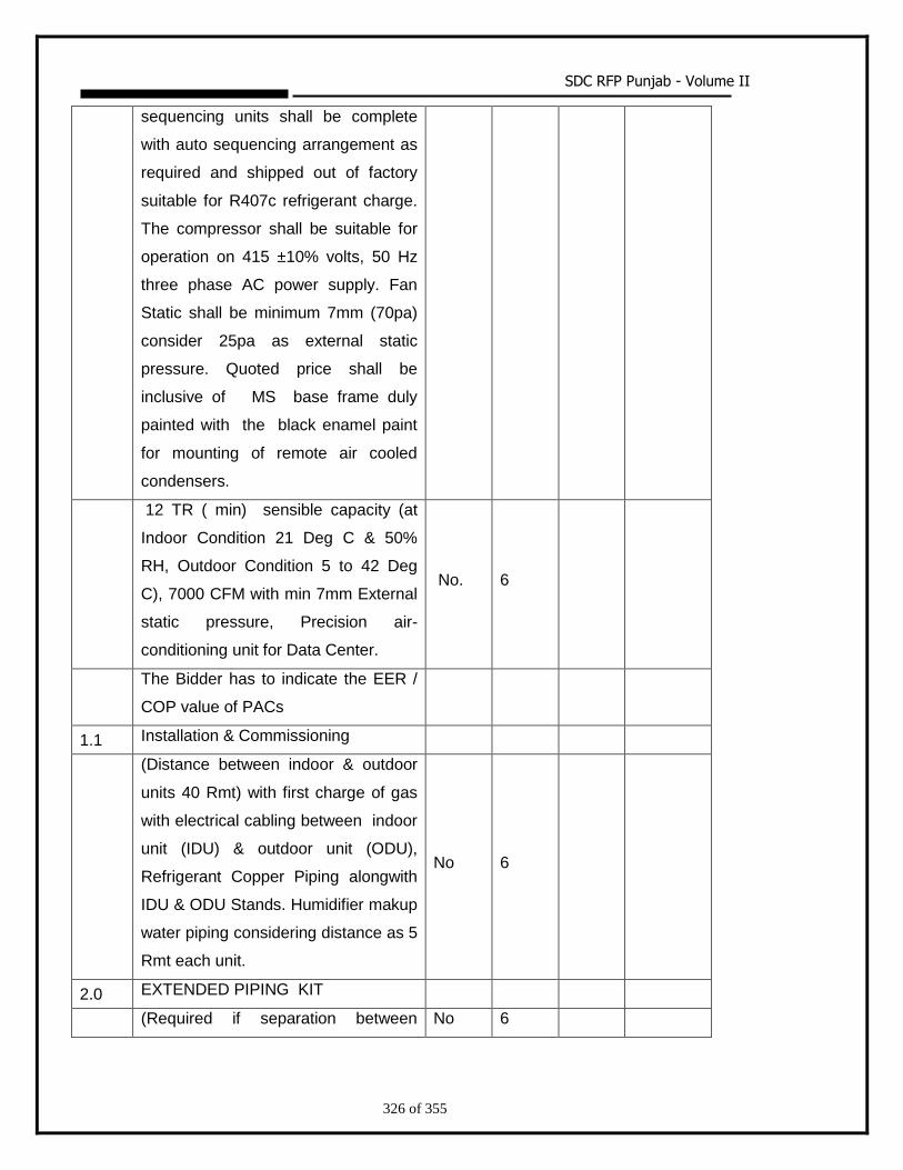
SDC RFP Punjab - Volume II
326 of 355
sequencing units shall be complete
with auto sequencing arrangement as
required and shipped out of factory
suitable for R407c refrigerant charge.
The compressor shall be suitable for
operation on 415 ±10% volts, 50 Hz
three phase AC power supply. Fan
Static shall be minimum 7mm (70pa)
consider 25pa as external static
pressure. Quoted price shall be
inclusive of MS base frame duly
painted with the black enamel paint
for mounting of remote air cooled
condensers.
12 TR ( min) sensible capacity (at
Indoor Condition 21 Deg C & 50%
RH, Outdoor Condition 5 to 42 Deg
C), 7000 CFM with min 7mm External
static pressure, Precision air-
conditioning unit for Data Center.
No. 6
The Bidder has to indicate the EER /
COP value of PACs
1.1 Installation & Commissioning
(Distance between indoor & outdoor
units 40 Rmt) with first charge of gas
with electrical cabling between indoor
unit (IDU) & outdoor unit (ODU),
Refrigerant Copper Piping alongwith
IDU & ODU Stands. Humidifier makup
water piping considering distance as 5
Rmt each unit.
No 6
2.0 EXTENDED PIPING KIT
(Required if separation between No 6
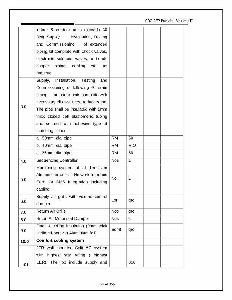
SDC RFP Punjab - Volume II
327 of 355
indoor & outdoor units exceeds 30
RM). Supply, Installation, Testing
and Commissioning of extended
piping kit complete with check valves,
electronic solenoid valves, u bends
copper piping, cabling etc. as
required.
3.0
Supply, Installation, Testing and
Commissioning of following GI drain
piping for indoor units complete with
necessary elbows, tees, reducers etc.
The pipe shall be insulated with 9mm
thick closed cell elastomeric tubing
and secured with adhesive type of
matching colour.
a. 50mm dia pipe RM 50
b. 40mm dia pipe RM R/O
c. 25mm dia pipe RM 60
4.0 Sequencing Controller Nos 1
5.0
Monitoring system of all Precision
Aircondition units - Network interface
Card for BMS Integration including
cabling
No 1
6.0 Supply air grills with volume control
damper Lot qro
7.0 Return Air Grills Nos qro
8.0 Retun Air Motorised Damper Nos 4
9.0 Floor & ceiling insulation (9mm thick
nitrile rubber with Aluminium foil) Sqmt qro
10.0 Comfort cooling system
01
2TR wall mounted Split AC system
with highest star rating ( highest
EER). The job include supply and 010
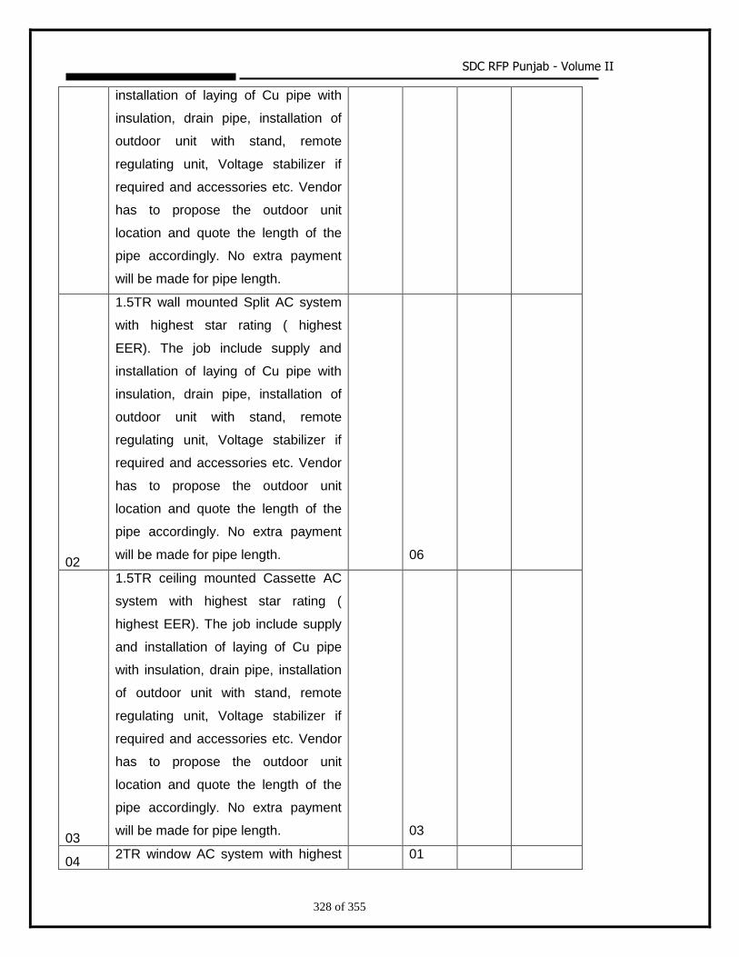
SDC RFP Punjab - Volume II
328 of 355
installation of laying of Cu pipe with
insulation, drain pipe, installation of
outdoor unit with stand, remote
regulating unit, Voltage stabilizer if
required and accessories etc. Vendor
has to propose the outdoor unit
location and quote the length of the
pipe accordingly. No extra payment
will be made for pipe length.
02
1.5TR wall mounted Split AC system
with highest star rating ( highest
EER). The job include supply and
installation of laying of Cu pipe with
insulation, drain pipe, installation of
outdoor unit with stand, remote
regulating unit, Voltage stabilizer if
required and accessories etc. Vendor
has to propose the outdoor unit
location and quote the length of the
pipe accordingly. No extra payment
will be made for pipe length. 06
03
1.5TR ceiling mounted Cassette AC
system with highest star rating (
highest EER). The job include supply
and installation of laying of Cu pipe
with insulation, drain pipe, installation
of outdoor unit with stand, remote
regulating unit, Voltage stabilizer if
required and accessories etc. Vendor
has to propose the outdoor unit
location and quote the length of the
pipe accordingly. No extra payment
will be made for pipe length. 03
04 2TR window AC system with highest 01
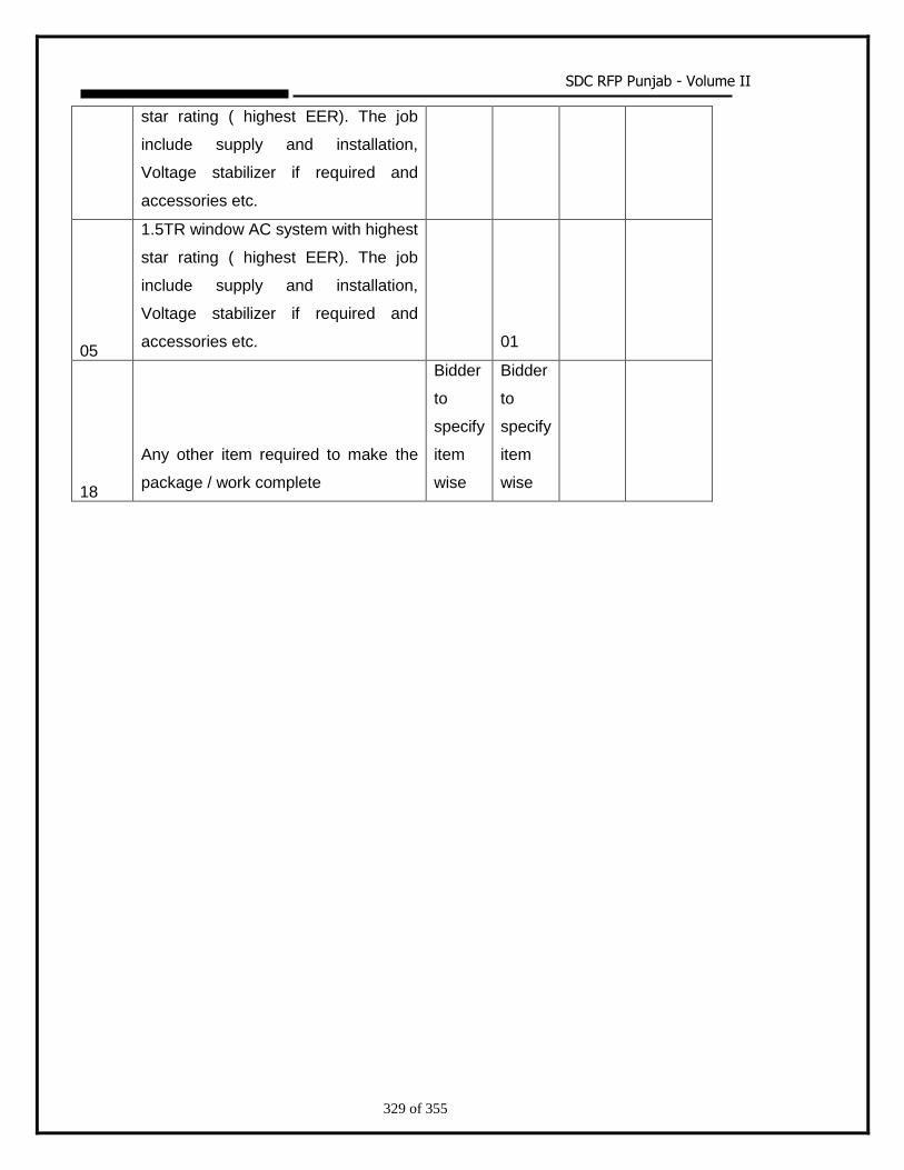
SDC RFP Punjab - Volume II
329 of 355
star rating ( highest EER). The job
include supply and installation,
Voltage stabilizer if required and
accessories etc.
05
1.5TR window AC system with highest
star rating ( highest EER). The job
include supply and installation,
Voltage stabilizer if required and
accessories etc. 01
18
Any other item required to make the
package / work complete
Bidder
to
specify
item
wise
Bidder
to
specify
item
wise
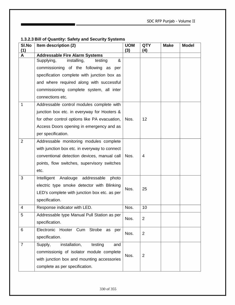
SDC RFP Punjab - Volume II
330 of 355
1.3.2.3 Bill of Quantity: Safety and Security Systems
Sl.No (1)
Item description (2) UOM (3)
QTY (4)
Make Model
A Addressable Fire Alarm Systems
Supplying, installing, testing &
commissioning of the following as per
specification complete with junction box as
and where required along with successful
commissioning complete system, all inter
connections etc.
1 Addressable control modules complete with
junction box etc. in everyway for Hooters &
for other control options like PA evacuation,
Access Doors opening in emergency and as
per specification.
Nos. 12
2 Addressable monitoring modules complete
with junction box etc. in everyway to connect
conventional detection devices, manual call
points, flow switches, supervisory switches
etc.
Nos. 4
3 Intelligent Analouge addressable photo
electric type smoke detector with Blinking
LED's complete with junction box etc. as per
specification.
Nos. 25
4 Response indicator with LED. Nos. 10
5 Addressable type Manual Pull Station as per
specification. Nos. 2
6 Electronic Hooter Cum Strobe as per
specification. Nos. 2
7 Supply, installation, testing and
commissionig of isolator module complete
with junction box and mounting accessories
complete as per specification.
Nos. 2
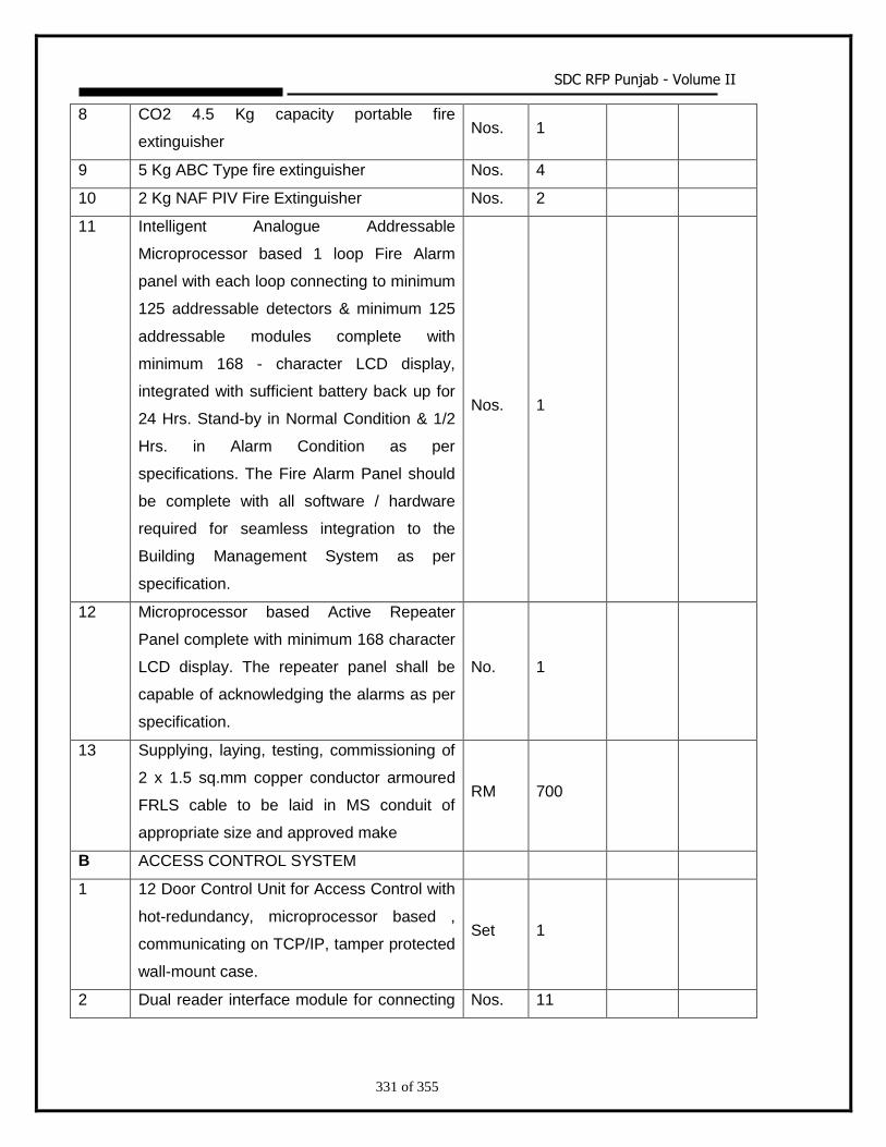
SDC RFP Punjab - Volume II
331 of 355
8 CO2 4.5 Kg capacity portable fire
extinguisher Nos. 1
9 5 Kg ABC Type fire extinguisher Nos. 4
10 2 Kg NAF PIV Fire Extinguisher Nos. 2
11 Intelligent Analogue Addressable
Microprocessor based 1 loop Fire Alarm
panel with each loop connecting to minimum
125 addressable detectors & minimum 125
addressable modules complete with
minimum 168 - character LCD display,
integrated with sufficient battery back up for
24 Hrs. Stand-by in Normal Condition & 1/2
Hrs. in Alarm Condition as per
specifications. The Fire Alarm Panel should
be complete with all software / hardware
required for seamless integration to the
Building Management System as per
specification.
Nos. 1
12 Microprocessor based Active Repeater
Panel complete with minimum 168 character
LCD display. The repeater panel shall be
capable of acknowledging the alarms as per
specification.
No. 1
13 Supplying, laying, testing, commissioning of
2 x 1.5 sq.mm copper conductor armoured
FRLS cable to be laid in MS conduit of
appropriate size and approved make
RM 700
B ACCESS CONTROL SYSTEM
1 12 Door Control Unit for Access Control with
hot-redundancy, microprocessor based ,
communicating on TCP/IP, tamper protected
wall-mount case.
Set 1
2 Dual reader interface module for connecting Nos. 11
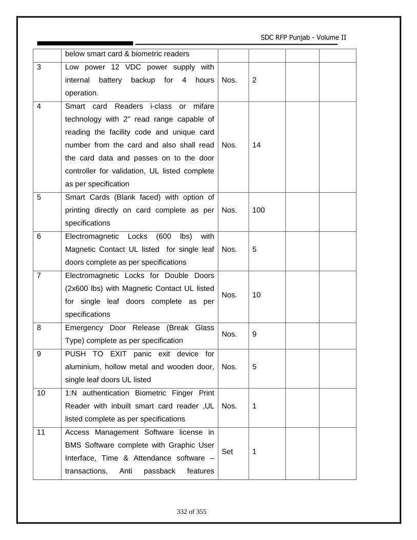
SDC RFP Punjab - Volume II
332 of 355
below smart card & biometric readers
3 Low power 12 VDC power supply with
internal battery backup for 4 hours
operation.
Nos. 2
4 Smart card Readers i-class or mifare
technology with 2" read range capable of
reading the facility code and unique card
number from the card and also shall read
the card data and passes on to the door
controller for validation, UL listed complete
as per specification
Nos. 14
5 Smart Cards (Blank faced) with option of
printing directly on card complete as per
specifications
Nos. 100
6 Electromagnetic Locks (600 lbs) with
Magnetic Contact UL listed for single leaf
doors complete as per specifications
Nos. 5
7 Electromagnetic Locks for Double Doors
(2x600 lbs) with Magnetic Contact UL listed
for single leaf doors complete as per
specifications
Nos. 10
8 Emergency Door Release (Break Glass
Type) complete as per specification Nos. 9
9 PUSH TO EXIT panic exit device for
aluminium, hollow metal and wooden door,
single leaf doors UL listed
Nos. 5
10 1:N authentication Biometric Finger Print
Reader with inbuilt smart card reader ,UL
listed complete as per specifications
Nos. 1
11 Access Management Software license in
BMS Software complete with Graphic User
Interface, Time & Attendance software –
transactions, Anti passback features
Set 1
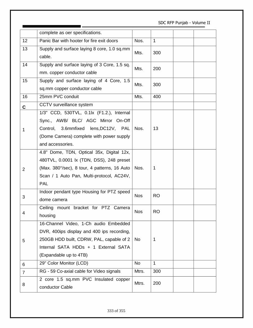
SDC RFP Punjab - Volume II
333 of 355
complete as oer specifications.
12 Panic Bar with hooter for fire exit doors Nos. 1
13 Supply and surface laying 8 core, 1.0 sq.mm
cable. Mts. 300
14 Supply and surface laying of 3 Core, 1.5 sq.
mm. copper conductor cable Mts. 200
15 Supply and surface laying of 4 Core, 1.5
sq.mm copper conductor cable Mts. 300
16 25mm PVC conduit Mts. 400
C CCTV surveillance system
1
1/3" CCD, 530TVL, 0.1lx (F1.2.), Internal
Sync., AWB/ BLC/ AGC Mirror On-Off
Control, 3.6mmfixed lens,DC12V, PAL
(Dome Camera) complete with power supply
and accessories.
Nos. 13
2
4.8" Dome, TDN, Optical 35x, Digital 12x,
480TVL, 0.0001 lx (TDN, DSS), 248 preset
(Max. 380°/sec), 8 tour, 4 patterns, 16 Auto
Scan / 1 Auto Pan, Multi-protocol, AC24V,
PAL
Nos. 1
3 Indoor pendant type Housing for PTZ speed
dome camera Nos RO
4 Ceiling mount bracket for PTZ Camera
housing Nos RO
5
16-Channel Video, 1-Ch audio Embedded
DVR, 400ips display and 400 ips recording,
250GB HDD built, CDRW, PAL, capable of 2
Internal SATA HDDs + 1 External SATA
(Expandable up to 4TB)
No 1
6 29" Color Monitor (LCD) No 1
7 RG - 59 Co-axial cable for Video signals Mtrs. 300
8 2 core 1.5 sq.mm PVC Insulated copper
conductor Cable Mtrs. 200
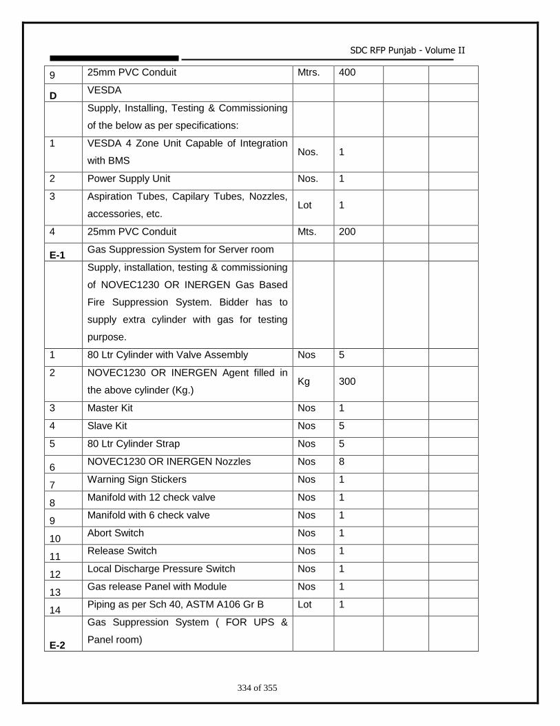
SDC RFP Punjab - Volume II
334 of 355
9 25mm PVC Conduit Mtrs. 400
D VESDA
Supply, Installing, Testing & Commissioning
of the below as per specifications:
1 VESDA 4 Zone Unit Capable of Integration
with BMS Nos. 1
2 Power Supply Unit Nos. 1
3 Aspiration Tubes, Capilary Tubes, Nozzles,
accessories, etc. Lot 1
4 25mm PVC Conduit Mts. 200
E-1 Gas Suppression System for Server room
Supply, installation, testing & commissioning
of NOVEC1230 OR INERGEN Gas Based
Fire Suppression System. Bidder has to
supply extra cylinder with gas for testing
purpose.
1 80 Ltr Cylinder with Valve Assembly Nos 5
2 NOVEC1230 OR INERGEN Agent filled in
the above cylinder (Kg.) Kg 300
3 Master Kit Nos 1
4 Slave Kit Nos 5
5 80 Ltr Cylinder Strap Nos 5
6 NOVEC1230 OR INERGEN Nozzles Nos 8
7 Warning Sign Stickers Nos 1
8 Manifold with 12 check valve Nos 1
9 Manifold with 6 check valve Nos 1
10 Abort Switch Nos 1
11 Release Switch Nos 1
12 Local Discharge Pressure Switch Nos 1
13 Gas release Panel with Module Nos 1
14 Piping as per Sch 40, ASTM A106 Gr B Lot 1
E-2
Gas Suppression System ( FOR UPS &
Panel room)
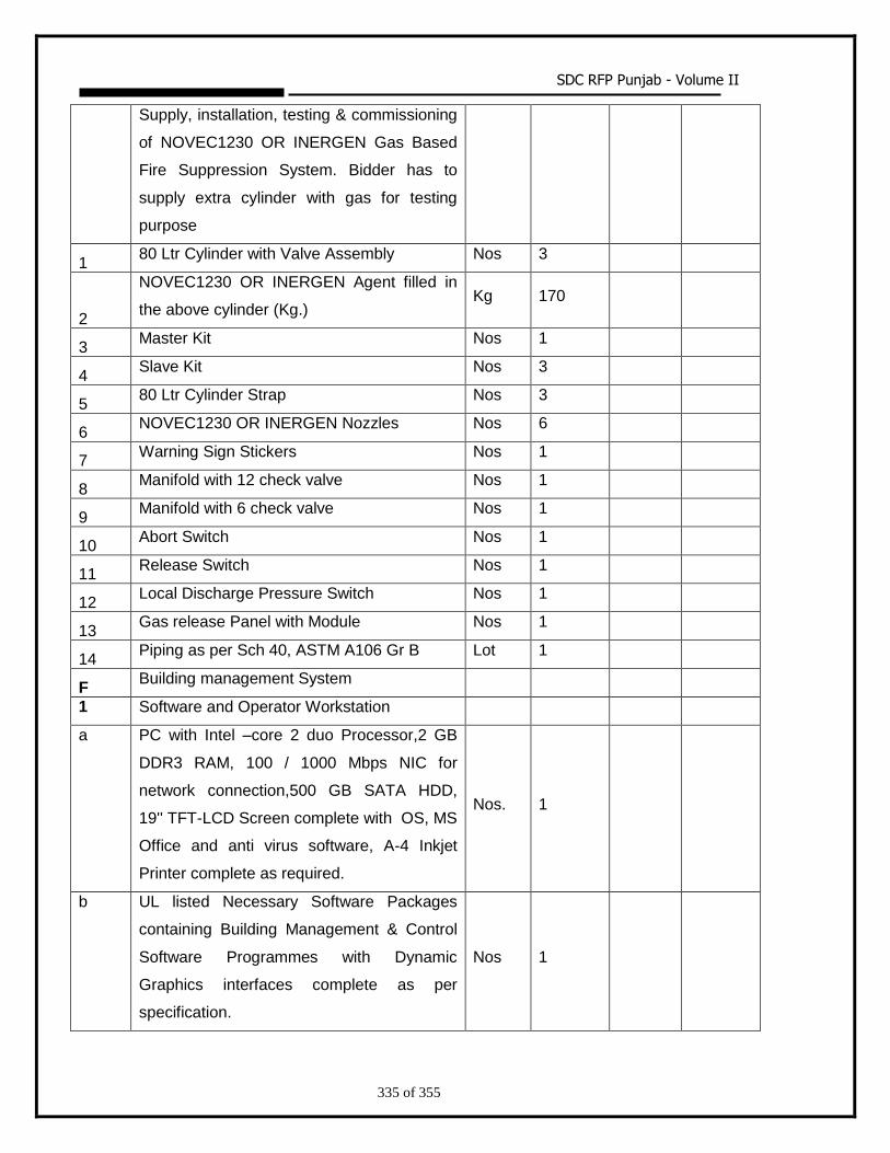
SDC RFP Punjab - Volume II
335 of 355
Supply, installation, testing & commissioning
of NOVEC1230 OR INERGEN Gas Based
Fire Suppression System. Bidder has to
supply extra cylinder with gas for testing
purpose
1 80 Ltr Cylinder with Valve Assembly Nos 3
2
NOVEC1230 OR INERGEN Agent filled in
the above cylinder (Kg.) Kg 170
3 Master Kit Nos 1
4 Slave Kit Nos 3
5 80 Ltr Cylinder Strap Nos 3
6 NOVEC1230 OR INERGEN Nozzles Nos 6
7 Warning Sign Stickers Nos 1
8 Manifold with 12 check valve Nos 1
9 Manifold with 6 check valve Nos 1
10 Abort Switch Nos 1
11 Release Switch Nos 1
12 Local Discharge Pressure Switch Nos 1
13 Gas release Panel with Module Nos 1
14 Piping as per Sch 40, ASTM A106 Gr B Lot 1
F Building management System
1 Software and Operator Workstation
a PC with Intel –core 2 duo Processor,2 GB
DDR3 RAM, 100 / 1000 Mbps NIC for
network connection,500 GB SATA HDD,
19'' TFT-LCD Screen complete with OS, MS
Office and anti virus software, A-4 Inkjet
Printer complete as required.
Nos. 1
b UL listed Necessary Software Packages
containing Building Management & Control
Software Programmes with Dynamic
Graphics interfaces complete as per
specification.
Nos 1
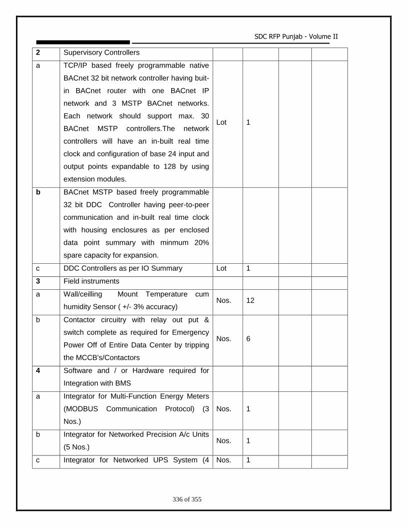
SDC RFP Punjab - Volume II
336 of 355
2 Supervisory Controllers
a TCP/IP based freely programmable native
BACnet 32 bit network controller having buit-
in BACnet router with one BACnet IP
network and 3 MSTP BACnet networks.
Each network should support max. 30
BACnet MSTP controllers.The network
controllers will have an in-built real time
clock and configuration of base 24 input and
output points expandable to 128 by using
extension modules.
Lot 1
b BACnet MSTP based freely programmable
32 bit DDC Controller having peer-to-peer
communication and in-built real time clock
with housing enclosures as per enclosed
data point summary with minmum 20%
spare capacity for expansion.
c DDC Controllers as per IO Summary Lot 1
3 Field instruments
a Wall/ceilling Mount Temperature cum
humidity Sensor ( +/- 3% accuracy) Nos. 12
b Contactor circuitry with relay out put &
switch complete as required for Emergency
Power Off of Entire Data Center by tripping
the MCCB's/Contactors
Nos. 6
4 Software and / or Hardware required for
Integration with BMS
a Integrator for Multi-Function Energy Meters
(MODBUS Communication Protocol) (3
Nos.)
Nos. 1
b Integrator for Networked Precision A/c Units
(5 Nos.) Nos. 1
c Integrator for Networked UPS System (4 Nos. 1
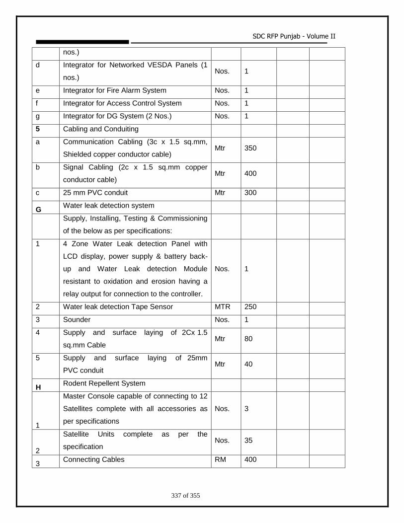
SDC RFP Punjab - Volume II
337 of 355
nos.)
d Integrator for Networked VESDA Panels (1
nos.) Nos. 1
e Integrator for Fire Alarm System Nos. 1
f Integrator for Access Control System Nos. 1
g Integrator for DG System (2 Nos.) Nos. 1
5 Cabling and Conduiting
a Communication Cabling (3c x 1.5 sq.mm,
Shielded copper conductor cable) Mtr 350
b Signal Cabling (2c x 1.5 sq.mm copper
conductor cable) Mtr 400
c 25 mm PVC conduit Mtr 300
G Water leak detection system
Supply, Installing, Testing & Commissioning
of the below as per specifications:
1 4 Zone Water Leak detection Panel with
LCD display, power supply & battery back-
up and Water Leak detection Module
resistant to oxidation and erosion having a
relay output for connection to the controller.
Nos. 1
2 Water leak detection Tape Sensor MTR 250
3 Sounder Nos. 1
4 Supply and surface laying of 2Cx 1.5
sq.mm Cable Mtr 80
5 Supply and surface laying of 25mm
PVC conduit Mtr 40
H Rodent Repellent System
1
Master Console capable of connecting to 12
Satellites complete with all accessories as
per specifications
Nos. 3
2
Satellite Units complete as per the
specification Nos. 35
3 Connecting Cables RM 400
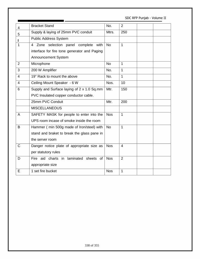
SDC RFP Punjab - Volume II
338 of 355
4 Bracket Stand No. 2
5 Supply & laying of 25mm PVC conduit Mtrs. 250
I Public Address System
1 4 Zone selection panel complete with
interface for fire tone generator and Paging
Announcement System
No 1
2 Microphone No 1
3 200 W Amplifier No. 1
4 19" Rack to mount the above No. 1
4 Ceiling Mount Speaker - 6 W Nos. 10
6 Supply and Surface laying of 2 x 1.0 Sq.mm
PVC Insulated copper conductor cable.
Mtr. 150
25mm PVC Conduit Mtr. 200
MISCELLANEOUS
A SAFETY MASK for people to enter into the
UPS room incase of smoke inside the room
Nos 1
B Hammer ( min 500g made of Iron/steel) with
stand and braket to break the glass pane in
the server room
No 1
C Danger notice plate of appropriate size as
per statutory rules
Nos 4
D Fire aid charts in laminated sheets of
appropriate size
Nos 2
E 1 set fire bucket Nos 1
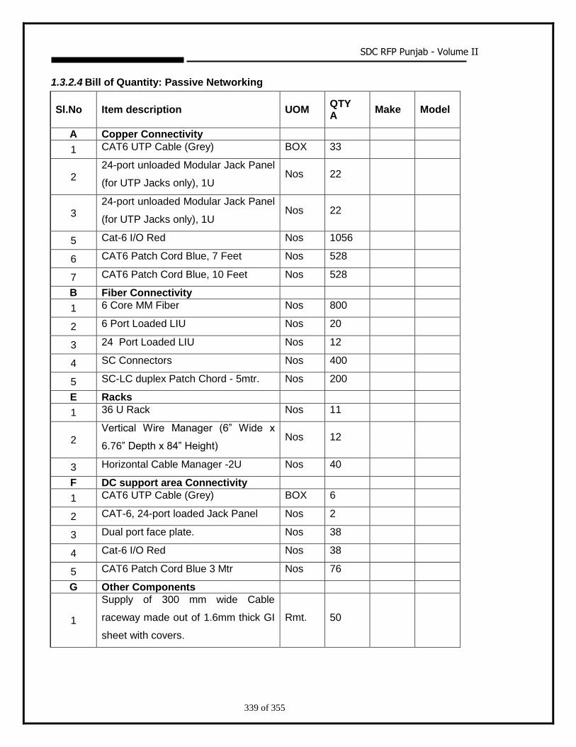
SDC RFP Punjab - Volume II
339 of 355
1.3.2.4 Bill of Quantity: Passive Networking
Sl.No Item description UOM QTY A
Make
Model
A Copper Connectivity
1 CAT6 UTP Cable (Grey) BOX 33
2 24-port unloaded Modular Jack Panel
(for UTP Jacks only), 1U Nos 22
3 24-port unloaded Modular Jack Panel
(for UTP Jacks only), 1U Nos 22
5 Cat-6 I/O Red Nos 1056
6 CAT6 Patch Cord Blue, 7 Feet Nos 528
7 CAT6 Patch Cord Blue, 10 Feet Nos 528
B Fiber Connectivity
1 6 Core MM Fiber Nos 800
2 6 Port Loaded LIU Nos 20
3 24 Port Loaded LIU Nos 12
4 SC Connectors Nos 400
5 SC-LC duplex Patch Chord - 5mtr. Nos 200
E Racks
1 36 U Rack Nos 11
2 Vertical Wire Manager (6” Wide x
6.76” Depth x 84” Height) Nos 12
3 Horizontal Cable Manager -2U Nos 40
F DC support area Connectivity
1 CAT6 UTP Cable (Grey) BOX 6
2 CAT-6, 24-port loaded Jack Panel Nos 2
3 Dual port face plate. Nos 38
4 Cat-6 I/O Red Nos 38
5 CAT6 Patch Cord Blue 3 Mtr Nos 76
G Other Components
1
Supply of 300 mm wide Cable
raceway made out of 1.6mm thick GI
sheet with covers.
Rmt. 50
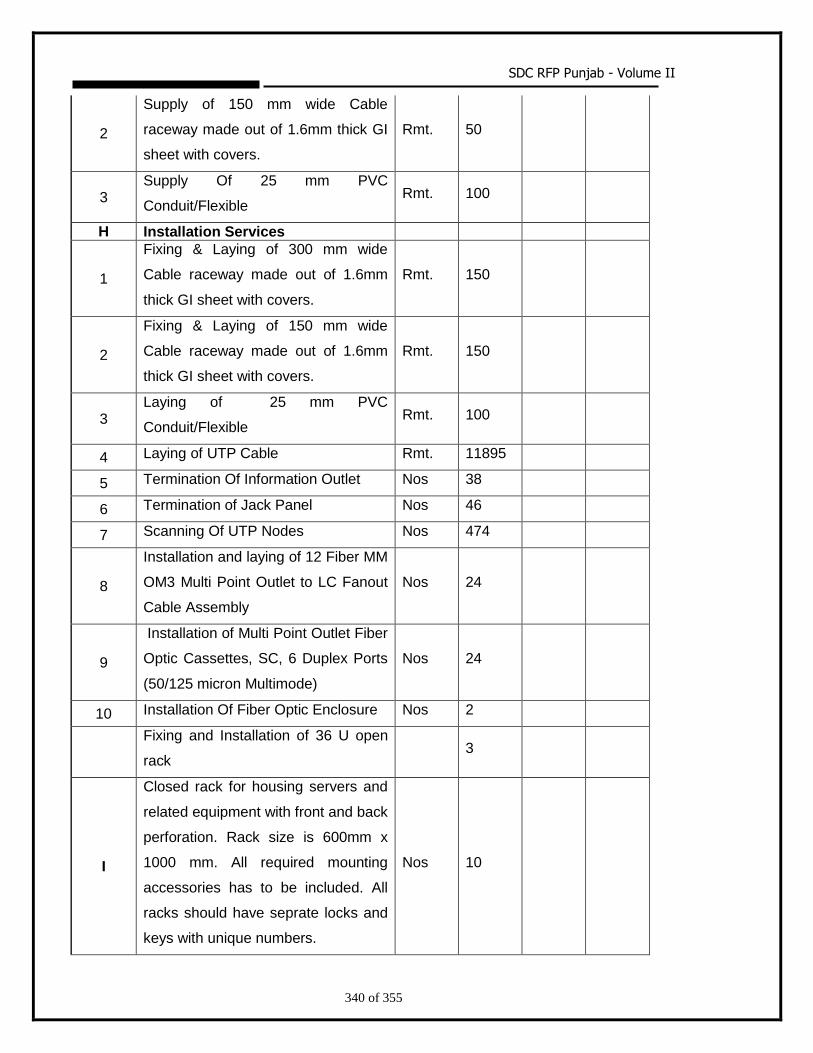
SDC RFP Punjab - Volume II
340 of 355
2
Supply of 150 mm wide Cable
raceway made out of 1.6mm thick GI
sheet with covers.
Rmt. 50
3 Supply Of 25 mm PVC
Conduit/Flexible Rmt. 100
H Installation Services
1
Fixing & Laying of 300 mm wide
Cable raceway made out of 1.6mm
thick GI sheet with covers.
Rmt. 150
2
Fixing & Laying of 150 mm wide
Cable raceway made out of 1.6mm
thick GI sheet with covers.
Rmt. 150
3 Laying of 25 mm PVC
Conduit/Flexible Rmt. 100
4 Laying of UTP Cable Rmt. 11895
5 Termination Of Information Outlet Nos 38
6 Termination of Jack Panel Nos 46
7 Scanning Of UTP Nodes Nos 474
8
Installation and laying of 12 Fiber MM
OM3 Multi Point Outlet to LC Fanout
Cable Assembly
Nos 24
9
Installation of Multi Point Outlet Fiber
Optic Cassettes, SC, 6 Duplex Ports
(50/125 micron Multimode)
Nos 24
10 Installation Of Fiber Optic Enclosure Nos 2
Fixing and Installation of 36 U open
rack 3
I
Closed rack for housing servers and
related equipment with front and back
perforation. Rack size is 600mm x
1000 mm. All required mounting
accessories has to be included. All
racks should have seprate locks and
keys with unique numbers.
Nos 10
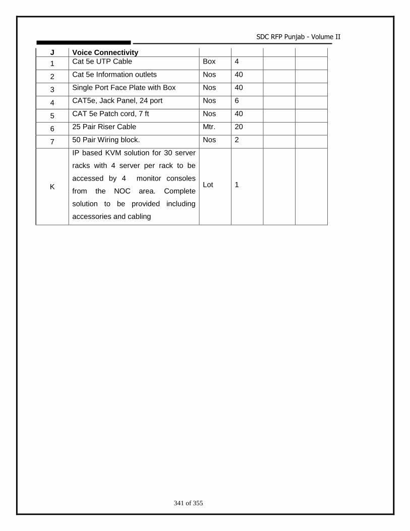
SDC RFP Punjab - Volume II
341 of 355
J Voice Connectivity
1 Cat 5e UTP Cable Box 4
2 Cat 5e Information outlets Nos 40
3 Single Port Face Plate with Box Nos 40
4 CAT5e, Jack Panel, 24 port Nos 6
5 CAT 5e Patch cord, 7 ft Nos 40
6 25 Pair Riser Cable Mtr. 20
7 50 Pair Wiring block. Nos 2
K
IP based KVM solution for 30 server
racks with 4 server per rack to be
accessed by 4 monitor consoles
from the NOC area. Complete
solution to be provided including
accessories and cabling
Lot 1
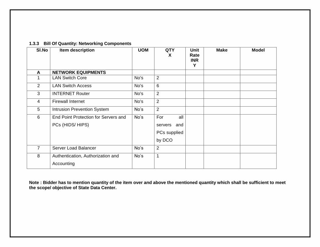
1.3.3 Bill Of Quantity: Networking Components
Sl.No Item description UOM QTY X
Unit Rate INR Y
Make Model
A NETWORK EQUIPMENTS
1 LAN Switch Core No's 2
2 LAN Switch Access No's 6
3 INTERNET Router No's 2
4 Firewall Internet No's 2
5 Intrusion Prevention System No’s 2
6 End Point Protection for Servers and
PCs (HIDS/ HIPS)
No’s For all
servers and
PCs supplied
by DCO
7 Server Load Balancer No’s 2
8 Authentication, Authorization and
Accounting
No’s 1
Note : Bidder has to mention quantity of the item over and above the mentioned quantity which shall be sufficient to meet the scope/ objective of State Data Center.
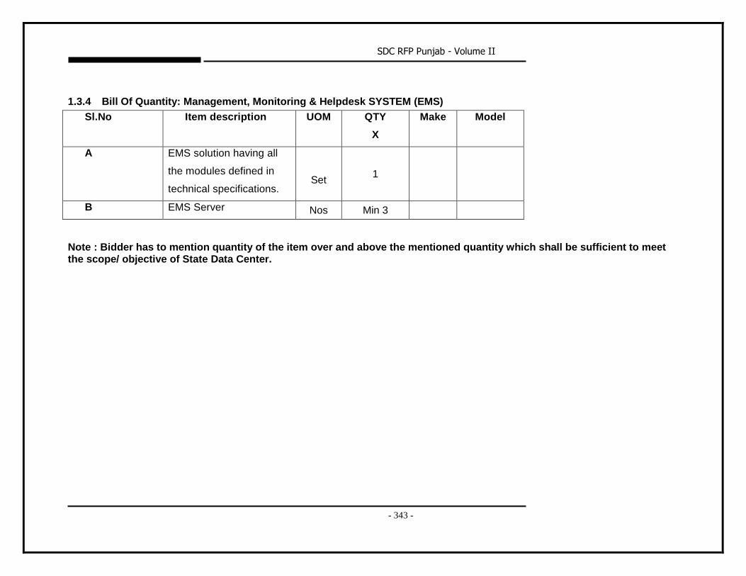
SDC RFP Punjab - Volume II
- 343 -
1.3.4 Bill Of Quantity: Management, Monitoring & Helpdesk SYSTEM (EMS)
Sl.No Item description UOM QTY
X
Make Model
A EMS solution having all
the modules defined in
technical specifications.
Set
1
B EMS Server Nos Min 3
Note : Bidder has to mention quantity of the item over and above the mentioned quantity which shall be sufficient to meet the scope/ objective of State Data Center.
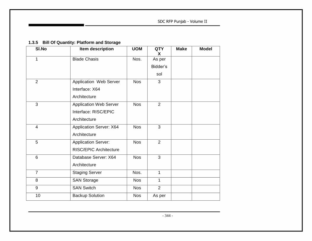
SDC RFP Punjab - Volume II
- 344 -
1.3.5 Bill Of Quantity: Platform and Storage
Sl.No Item description UOM QTY X
Make Model
1 Blade Chasis Nos. As per
Bidder’s
sol
2 Application Web Server
Interface: X64
Architecture
Nos 3
3 Application Web Server
Interface: RISC/EPIC
Architecture
Nos 2
4 Application Server: X64
Architecture
Nos 3
5 Application Server:
RISC/EPIC Architecture
Nos 2
6 Database Server: X64
Architecture
Nos 3
7 Staging Server Nos. 1
8 SAN Storage Nos 1
9 SAN Switch Nos 2
10 Backup Solution Nos As per
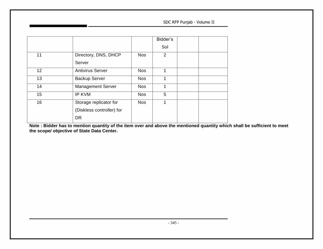
SDC RFP Punjab - Volume II
- 345 -
Bidder’s
Sol
11 Directory, DNS, DHCP
Server
Nos 2
12 Antivirus Server Nos 1
13 Backup Server Nos 1
14 Management Server Nos 1
15 IP KVM Nos 5
16 Storage replicator for
(Diskless controller) for
DR
Nos 1
Note : Bidder has to mention quantity of the item over and above the mentioned quantity which shall be sufficient to meet the scope/ objective of State Data Center.
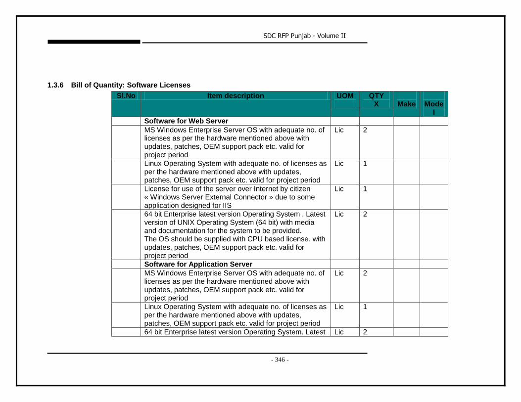
SDC RFP Punjab - Volume II
- 346 -
1.3.6 Bill of Quantity: Software Licenses
Sl.No Item description UOM
QTY X
Make
Mode
l
i. Software for Web Server
ii. MS Windows Enterprise Server OS with adequate no. of licenses as per the hardware mentioned above with updates, patches, OEM support pack etc. valid for project period
Lic 2
iii. Linux Operating System with adequate no. of licenses as per the hardware mentioned above with updates, patches, OEM support pack etc. valid for project period
Lic 1
iv. License for use of the server over Internet by citizen « Windows Server External Connector » due to some application designed for IIS
Lic 1
v. 64 bit Enterprise latest version Operating System . Latest version of UNIX Operating System (64 bit) with media and documentation for the system to be provided. The OS should be supplied with CPU based license. with updates, patches, OEM support pack etc. valid for project period
Lic 2
Software for Application Server
MS Windows Enterprise Server OS with adequate no. of licenses as per the hardware mentioned above with updates, patches, OEM support pack etc. valid for project period
Lic 2
Linux Operating System with adequate no. of licenses as per the hardware mentioned above with updates, patches, OEM support pack etc. valid for project period
Lic 1
64 bit Enterprise latest version Operating System. Latest Lic 2
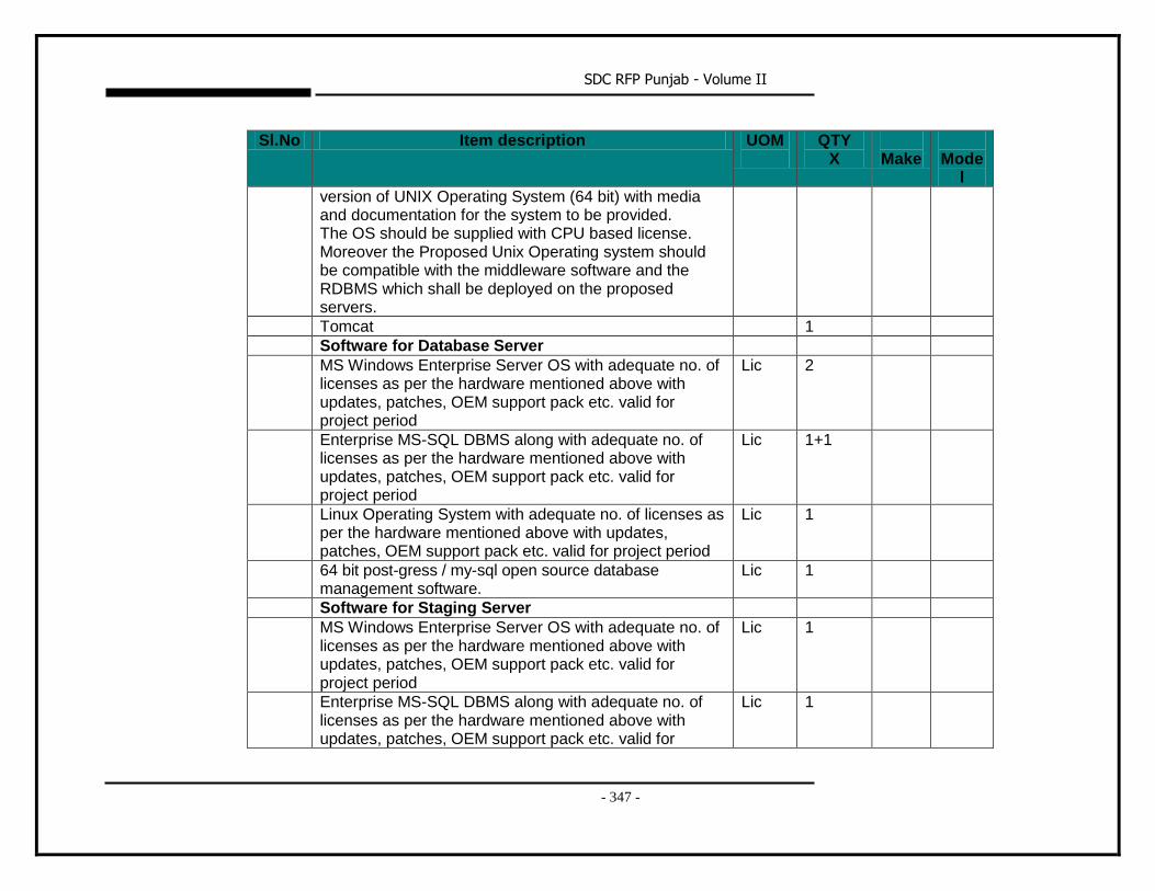
SDC RFP Punjab - Volume II
- 347 -
Sl.No Item description UOM
QTY X
Make
Mode
l
version of UNIX Operating System (64 bit) with media and documentation for the system to be provided. The OS should be supplied with CPU based license. Moreover the Proposed Unix Operating system should be compatible with the middleware software and the RDBMS which shall be deployed on the proposed servers.
Tomcat 1
vi. Software for Database Server
MS Windows Enterprise Server OS with adequate no. of licenses as per the hardware mentioned above with updates, patches, OEM support pack etc. valid for project period
Lic 2
Enterprise MS-SQL DBMS along with adequate no. of licenses as per the hardware mentioned above with updates, patches, OEM support pack etc. valid for project period
Lic 1+1
Linux Operating System with adequate no. of licenses as per the hardware mentioned above with updates, patches, OEM support pack etc. valid for project period
Lic 1
64 bit post-gress / my-sql open source database management software.
Lic 1
vii. Software for Staging Server
MS Windows Enterprise Server OS with adequate no. of licenses as per the hardware mentioned above with updates, patches, OEM support pack etc. valid for project period
Lic 1
Enterprise MS-SQL DBMS along with adequate no. of licenses as per the hardware mentioned above with updates, patches, OEM support pack etc. valid for
Lic 1
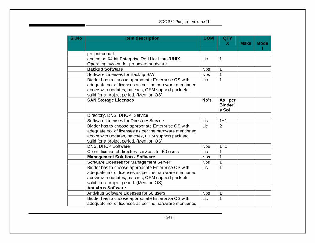
SDC RFP Punjab - Volume II
- 348 -
Sl.No Item description UOM
QTY X
Make
Mode
l
project period
viii. one set of 64 bit Enterprise Red Hat Linux/UNIX Operating system for proposed hardware.
Lic 1
ix. Backup Software Nos 1
x. Software Licenses for Backup S/W Nos 1
Bidder has to choose appropriate Enterprise OS with adequate no. of licenses as per the hardware mentioned above with updates, patches, OEM support pack etc. valid for a project period. (Mention OS)
Lic 1
xi. SAN Storage Licenses No’s As per Bidder’s Sol
xii. Directory, DNS, DHCP Service
xiii. Software Licenses for Directory Service Lic 1+1
Bidder has to choose appropriate Enterprise OS with adequate no. of licenses as per the hardware mentioned above with updates, patches, OEM support pack etc. valid for a project period. (Mention OS)
Lic 2
xiv. DNS, DHCP Software Nos 1+1
Client license of directory services for 50 users Lic 1
Management Solution - Software Nos 1
xv. Software Licenses for Management Server Nos 1
xvi. Bidder has to choose appropriate Enterprise OS with adequate no. of licenses as per the hardware mentioned above with updates, patches, OEM support pack etc. valid for a project period. (Mention OS)
Lic 1
Antivirus Software
Antivirus Software Licenses for 50 users Nos 1
Bidder has to choose appropriate Enterprise OS with adequate no. of licenses as per the hardware mentioned
Lic 1
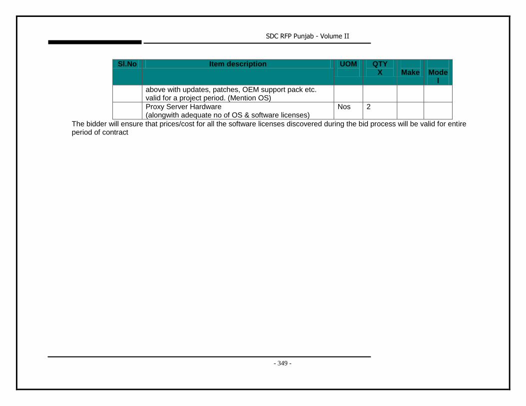
SDC RFP Punjab - Volume II
- 349 -
Sl.No Item description UOM
QTY X
Make
Mode
l
above with updates, patches, OEM support pack etc. valid for a project period. (Mention OS)
Proxy Server Hardware (alongwith adequate no of OS & software licenses)
Nos 2
The bidder will ensure that prices/cost for all the software licenses discovered during the bid process will be valid for entire period of contract
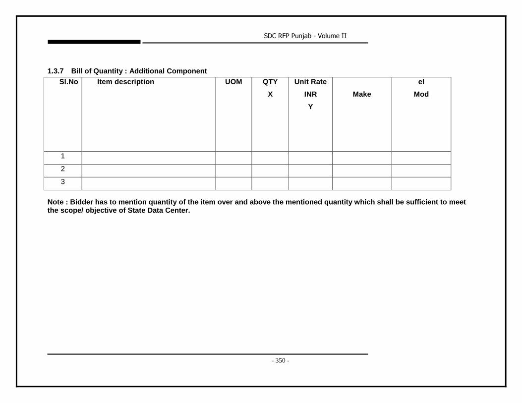
SDC RFP Punjab - Volume II
- 350 -
1.3.7 Bill of Quantity : Additional Component
Sl.No Item description UOM QTY
X
Unit Rate
INR
Y
Make
el
Mod
1
2
3
Note : Bidder has to mention quantity of the item over and above the mentioned quantity which shall be sufficient to meet the scope/ objective of State Data Center.
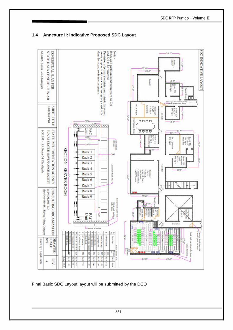
SDC RFP Punjab - Volume II
- 351 -
1.4 Annexure II: Indicative Proposed SDC Layout
Final Basic SDC Layout layout will be submitted by the DCO
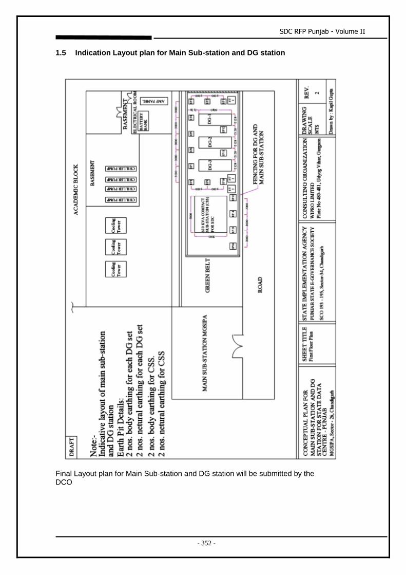
SDC RFP Punjab - Volume II
- 352 -
1.5 Indication Layout plan for Main Sub-station and DG station
Final Layout plan for Main Sub-station and DG station will be submitted by the DCO
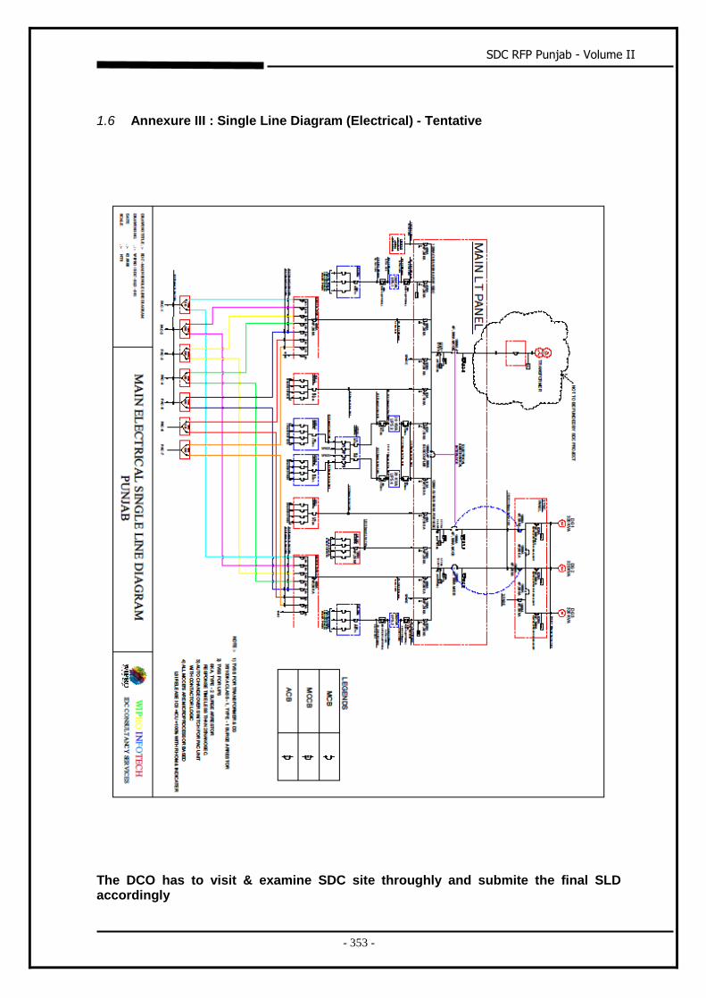
SDC RFP Punjab - Volume II
- 353 -
1.6 Annexure III : Single Line Diagram (Electrical) - Tentative
The DCO has to visit & examine SDC site throughly and submite the final SLD accordingly
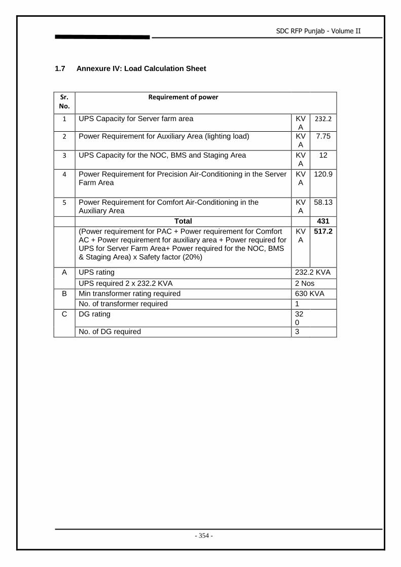
SDC RFP Punjab - Volume II
- 354 -
1.7 Annexure IV: Load Calculation Sheet
Sr. No.
Requirement of power
1 UPS Capacity for Server farm area KVA
232.2
2 Power Requirement for Auxiliary Area (lighting load) KVA
7.75
3 UPS Capacity for the NOC, BMS and Staging Area KVA
12
4 Power Requirement for Precision Air-Conditioning in the Server Farm Area
KVA
120.9
5 Power Requirement for Comfort Air-Conditioning in the Auxiliary Area
KVA
58.13
Total 431
(Power requirement for PAC + Power requirement for Comfort AC + Power requirement for auxiliary area + Power required for UPS for Server Farm Area+ Power required for the NOC, BMS & Staging Area) x Safety factor (20%)
KVA
517.2
A UPS rating 232.2 KVA
UPS required 2 x 232.2 KVA 2 Nos
B Min transformer rating required 630 KVA
No. of transformer required 1
C DG rating 320
No. of DG required 3
SDC RFP Punjab - Volume II
- 355 -
Site constraint
Bidder shall visit and examine the site thoroughly and get all the relevant information
related to site constraints and submit the solution bid accordingly.
Any additional scope which is to be carried out due to site constraint should
be mentioned in the BOQ as one line item.
No separate line items for each scope related to site constraint should be
provided in the Commercial Bid.
Bidder will provide the lump sum cost for the entire scope related to site
constraint.
No additional claim related to site constraint other than the lump sum cost approved by State Implementation Agency (SIA) in the BOQ will be entertained by the SIA.
All the allied & implied work shall be in the scope of bidder for satisfactory operation of the State Data Centre (SDC).
Scope related to functionality of each equipment as per the design requirement shall be Bidder Scope of work.
The Bidder shall carry out all the tasks in accordance with the
requirement of SDC with due diligence and it shall be the responsibility of
the Bidder to fully meet all the requirements of State Data Centre(SDC).