pu/ne-98-10 software design and implementation …
TRANSCRIPT

PU/NE-98-10
SOFTWARE DESIGN AND IMPLEMENTATION DOCUMENTFOR THE GENERAL INTERFACE IN THE COUPLED CODE
Douglas A. Barber, Thomas J. Downar
School of Nuclear EngineeringPurdue University
W. Lafayette, IN 47907-1290
submitted to:
Division of Systems TechnologyOffice of Regulatory Research
Nuclear Regulatory CommissionWashington, D.C. 20555-001
Contract NRC-04-96-060, Task 5cPerformed Under Subcontract to SCIENTECH, Inc.
May 1998
11/14/98 - PU/NE-98-10 (Final) - 2
ftware
i-muni-assing
l all
thencon-
h the
paratee vari-riablestronic, which
whiche thetorage
nts in
nalsoamic
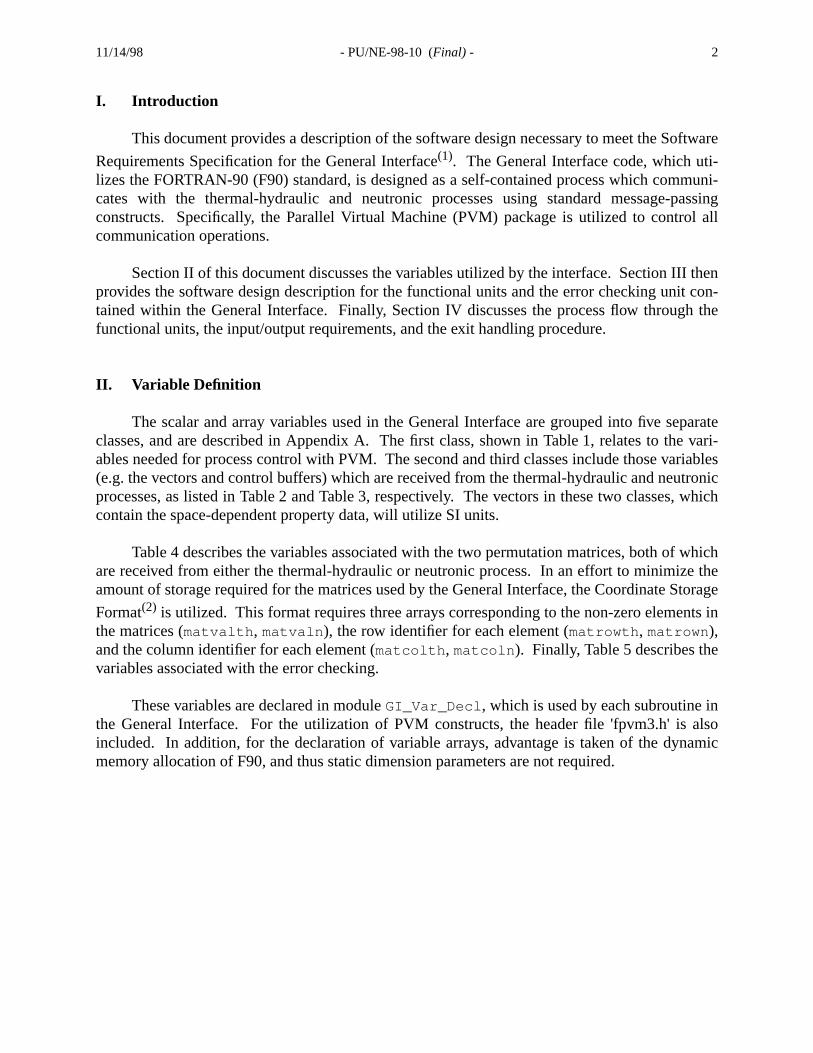
I. Introduction
This document provides a description of the software design necessary to meet the So
Requirements Specification for the General Interface(1). The General Interface code, which utlizes the FORTRAN-90 (F90) standard, is designed as a self-contained process which comcates with the thermal-hydraulic and neutronic processes using standard message-pconstructs. Specifically, the Parallel Virtual Machine (PVM) package is utilized to controcommunication operations.
Section II of this document discusses the variables utilized by the interface. Section IIIprovides the software design description for the functional units and the error checking unittained within the General Interface. Finally, Section IV discusses the process flow througfunctional units, the input/output requirements, and the exit handling procedure.
II. Variable Definition
The scalar and array variables used in the General Interface are grouped into five seclasses, and are described in Appendix A. The first class, shown in Table 1, relates to thables needed for process control with PVM. The second and third classes include those va(e.g. the vectors and control buffers) which are received from the thermal-hydraulic and neuprocesses, as listed in Table 2 and Table 3, respectively. The vectors in these two classescontain the space-dependent property data, will utilize SI units.
Table 4 describes the variables associated with the two permutation matrices, both ofare received from either the thermal-hydraulic or neutronic process. In an effort to minimizamount of storage required for the matrices used by the General Interface, the Coordinate S
Format(2) is utilized. This format requires three arrays corresponding to the non-zero elemethe matrices (matvalth , matvaln ), the row identifier for each element (matrowth , matrown ),and the column identifier for each element (matcolth , matcoln ). Finally, Table 5 describes thevariables associated with the error checking.
These variables are declared in moduleGI_Var_Decl , which is used by each subroutine ithe General Interface. For the utilization of PVM constructs, the header file 'fpvm3.h' isincluded. In addition, for the declaration of variable arrays, advantage is taken of the dynmemory allocation of F90, and thus static dimension parameters are not required.

11/14/98 - PU/NE-98-10 (Final) - 3
. Thether-s the
pro-ulic ortionalperty
g unit,.
ar inod-
ainedtrol-
andso willcoher-ed mes-
c and
III. Software Design
The General Interface code contains three functional units and one error checking unitfirst functional unit initializes the PVM process and establishes the communication with themal-hydraulic and neutronic processes. Following this setup, the initialization unit managecommunication of initial control information between the thermal-hydraulic and neutroniccesses. In addition, both permutation matrices are received from either the thermal-hydraneutronic process and stored for use in the two mapping units. The second and third funcunits handle both the transfer of time-dependent control information and the mapping of prodata between the thermal-hydraulic and neutronic processes. Finally, in the error checkintests are performed to ensure that the information sent to the General Interface is accurate
For organization of the subroutines, advantage is take of the F90MODULEconstruct. Aswill be shown in the following subsections, modules are utilized to group subroutines similfunction. Specifically, the subroutines associated with the initialization are contained within mule GI_Init_Calc , the subroutines associated with the time-dependent mappings are contwithin moduleGI_Time_Calc , the subroutines associated with the communication of conbuffers between processes are contained within moduleGI_Comm_Buf, and the subroutines associated with the error checking are contained within moduleGI_Error_Check . A brief descrip-tion of the subroutines and modules, along with a calling tree, is provided in Appendix B.
III.A. Initialization
The initialization procedure is controlled by the subroutine,GI_Init() . The subroutinescalled byGI_Init() are contained within moduleGI_Init_Calc .
The first step of the initialization is to invoke the PVM process for the General Interface,obtain the process ID. This process is then added to a dynamic process group, which alinclude the thermal-hydraulic and neutronic processes. In order to ensure communicationency, the process IDs are communicated between the three processes using predeterminsage tags (mtypegi, mtypeth, mtypen ). SubroutineGI_Obtain_IDs() performs thesefunctions for the General Interface, and a similar routine is needed in the thermal-hydraulineutronic codes. As an example, the following depicts the logic needed in each code:
General Interface Process:
c Establish communication with the Thermal-Hydraulicc and Neutronic processes. ntasks = 3 mtypegi = 1 mtypeth = 2 mtypen = 3 group = ’procs’c Enroll General Interface process in PVM. CALL pvmfmytid( tidgi)c Join the dynamic process group and wait for the thermal-hydraulicc and neutronic processes.

11/14/98 - PU/NE-98-10 (Final) - 4
CALL pvmfjoingroup( group, inum) CALL pvmfbarrier( group, ntasks, info)c Broadcast ID to the thermal-hydraulic and neutronic processes. CALL pvmfinitsend( PVMDEFAULT, info) CALL pvmfpack( INTEGER4, tidgi, 1, 1, info) CALL pvmfbcast( group, mtypegi, info)c Obtain IDs from the thermal-hydraulic and neutronic processes. CALL pvmftrecv( -1, mtypeth, timeout, 0, info) CALL pvmfunpack( INTEGER4, tidth, 1, 1, info) CALL pvmftrecv( -1, mtypen, timeout, 0, info) CALL pvmfunpack( INTEGER4, tidn, 1, 1, info)
Thermal-Hydraulic Process:
c Establish communication with the General Interface process. ntasks = 3 mtypegi = 1 mtypeth = 2 group = ’procs’c Enroll Thermal-Hydraulic process in PVM. CALL pvmfmytid( tidth)c Join the dynamic process group and wait for the General Interfacec and neutronic processes. CALL pvmfjoingroup( group, inum) CALL pvmfbarrier( group, ntasks, info)c Receive ID broadcasted from the General Interface process. CALL pvmftrecv( -1, mtypegi, timeout, 0, info) CALL pvmfunpack( INTEGER4, tidgi, 1, 1, info)c Send ID to the General Interface process. CALL pvmfinitsend( PVMDEFAULT, info) CALL pvmfpack( INTEGER4, tidth, 1, 1, info) CALL pvmfsend( tidgi, mtypeth, info)
Neutronic Process:
c Establish communication with the General Interface process. ntasks = 3 mtypegi = 1 mtypen = 3 group = ’procs’c Enroll Neutronic process in PVM. CALL pvmfmytid( tidn)c Join the dynamic process group and wait for the General Interfacec and thermal-hydraulic processes. CALL pvmfjoingroup( group, inum) CALL pvmfbarrier( group, ntasks, info)c Receive ID broadcasted from the General Interface process. CALL pvmftrecv( -1, mtypegi, timeout, 0, info) CALL pvmfunpack( INTEGER4, tidgi, 1, 1, info)c Send ID to the General Interface process. CALL pvmfinitsend( PVMDEFAULT, info) CALL pvmfpack( INTEGER4, tidn, 1, 1, info) CALL pvmfsend( tidgi, mtypen, info)

11/14/98 - PU/NE-98-10 (Final) - 5
-n isnica-
de will
ove
hichrs
uffers
red inmal-Inter-
atri-
sent to
The result of this example is thattidgi is associated with the General Interface,tidth isassociated with the thermal-hydraulic module, andtidn is associated with the neutronics module. With the process IDs for each module known explicitly, the communication initializatiocomplete. It should be noted that utilizing this design to establish the inter-process commution restricts the number of simultaneous jobs to one. In addition, thepvmfbarrier call doesnot have an associated “time-out”. Therefore, if all three processes are not started, the cobe stalled indefinitely.
The function,pvmftrecv , which is used throughout the code and was shown in the abexample, is a non-blocking receive which terminates if no message has arrived after “timeout ”seconds.timeout , which is described in Table 1 of Appendix A, is set to 600 seconds.
The next step is to receive the initial control information from the neutronic process, wis controlled by the subroutineGI_Buf_Init() . The routines used to communicate the buffe(i.e. GI_Recv_Bufn and GI_Send_Bufn ) are contained in moduleGI_Comm_Buf. The neu-tronic control information is sent to the General Interface as a structure composed of the bcorresponding to each data type (i.e.cbufn, lbufn, i2bufn, i4bufn, r4bufn,r8bufn ). Therefore, upon receipt of this structure, the data is unpacked and temporarily stomemory. Most of the information transferred in the control buffers is needed only by the therhydraulic process. However, the following locations are allocated for access by the Generalface:
lbufn(1) : Indication of an error in the Neutronic code.lbufn(2) : Indication of a data error in the Neutronic-Specific Data Map Routine.lbufn(3) : Indication of a PVM error in the Neutronic-Specific Data Map Routine.lbufn(4) : Indication of a data error in the General Interface.lbufn(5) : Indication of a PVM error in the General Interface.lbufn(6) : Indication of normal calculation termination.lbufn(7) : Indication of whether Neutronic process is sending the permutation m
ces.
Once this information has been extracted, the buffers are packed back into a structure andthe thermal-hydraulic process. The following coding example depicts this procedure:
c Receive data structure from neutronic process. CALL pvmftrecv( tidn, mtypen, timeout, 0, info) istride = 1c Extract buffer dimensions and allocate memory for thec control buffers. CALL pvmfunpack( INTEGER4, dimbuf, 6, istride, info) ALLOCATE( cbufn(dimbuf(1))) ALLOCATE( lbufn(dimbuf(2))) ALLOCATE( i2bufn(dimbuf(3))) ALLOCATE( i4bufn(dimbuf(4))) ALLOCATE( r4bufn(dimbuf(5))) ALLOCATE( r8bufn(dimbuf(6)))c Extract data type-dependent control buffers. CALL pvmfunpack( STRING, cbufn, 6*dimbuf(1), istride, info)

11/14/98 - PU/NE-98-10 (Final) - 6
aulic
utronicutinesedneu-
erface
.
atri-utine
CALL pvmfunpack( INTEGER4, lbufn, dimbuf(2), istride, info) CALL pvmfunpack( INTEGER2, i2bufn, dimbuf(3), istride, info) CALL pvmfunpack( INTEGER4, i4bufn, dimbuf(4), istride, info) CALL pvmfunpack( REAL4, r4bufn, dimbuf(5), istride, info) CALL pvmfunpack( REAL8, r8bufn, dimbuf(6), istride, info)
c extract any necessary information used by this routine
...
istride = 1 CALL pvmfinitsend( PVMDEFAULT, info)c Pack buffer dimensions. CALL pvmfpack( INTEGER4, dimbuf, 6, istride, info)c Pack data type-dependent buffers. CALL pvmfpack( STRING, cbufn, 6*dimbuf(1), istride, info) CALL pvmfpack( INTEGER4, lbufn, dimbuf(2), istride, info) CALL pvmfpack( INTEGER2, i2bufn, dimbuf(3), istride, info) CALL pvmfpack( INTEGER4, i4bufn, dimbuf(4), istride, info) CALL pvmfpack( REAL4, r4bufn, dimbuf(5), istride, info) CALL pvmfpack( REAL8, r8bufn, dimbuf(6), istride, info)c Send structure to thermal-hydraulic process. CALL pvmfsend( tidth, mtypegi, info)c Deallocate memory for the control buffers. DEALLOCATE( cbufn) DEALLOCATE( lbufn) DEALLOCATE( i2bufn) DEALLOCATE( i4bufn) DEALLOCATE( r4bufn) DEALLOCATE( r8bufn)
Once the neutronic initial control buffers have been communicated, the thermal-hydrinitial control buffers (i.e. cbufth, lbufth, i2bufth, i4bufth, r4bufth, r8bufth )are received, the necessary information is extracted, and the buffers are then sent to the neprocess. The coding needed to perform these tasks, which is contained in subroGI_Recv_Bufth() andGI_Send_Bufth() , is similar to that shown above and is not repeathere. Again, most of the information transferred in the control buffers is needed only by thetronic process. However, the following locations are allocated for access by the General Int
lbufth(1) : Indication of an error in the T/H code.lbufth(2) : Indication of a data error in the T/H-Specific Data Map Routine.lbufth(3) : Indication of a PVM error in the T/H-Specific Data Map Routine.lbufth(4) : Indication of a data error in the General Interface.lbufth(5) : Indication of a PVM error in the General Interface.lbufth(6) : Indication of normal calculation termination.lbufth(7) : Indication of whether T/H process is sending the permutation matrices
The final step in the initialization process is to receive and store the two permutation mces sent from either the thermal-hydraulic or the neutronic process, and subroGI_Recv_Mat() performs these tasks. The logical flagsrecvth and recvn , described in

11/14/98 - PU/NE-98-10 (Final) - 7
rdinateufferbuffer
eiv-
lrmal-
e sentracted
Table 2 and Table 3 respectively, indicate which process sends the matrices. Since the CooStorage Format is utilized for the matrices, two structures, each containing the matrix bdimension and the three arrays, are sent to the General Interface. Upon receipt, the matrixdimension is retrieved first and used to unpack and store the matrix into the arraysmatval*,matrow*, matcol* , which are described in Table 4. The following example depicts the recing and unpacking of the matrices:
IF (recvth) THENc Receive the structure from the thermal-hydraulic process. CALL pvmftrecv( tidth, mtypeth, timeout, 0, info) ENDIF IF (recvn) THENc Receive the structure from the neutronic process. CALL pvmftrecv( tidn, mtypen, timeout, 0, info) ENDIF
istride = 1c Unpack buffer dimensions for the permutation matrices. CALL pvmfunpack( INTEGER4, nmatth, 1, istride, info) CALL pvmfunpack( INTEGER4, nmatn, 1, istride, info)c Allocate memory for the permutation matrices. ALLOCATE( matvalth(nmatth)) ALLOCATE( matrowth(nmatth)) ALLOCATE( matcolth(nmatth)) ALLOCATE( matvaln(nmatn)) ALLOCATE( matrown(nmatn)) ALLOCATE( matcoln(nmatn))c Unpack thermal-hydraulic/heat structure to neutronic matrix. CALL pvmfunpack( REAL8, matvalth, nmatth, istride, info) CALL pvmfunpack( INTEGER4, matrowth, nmatth, istride, info) CALL pvmfunpack( INTEGER4, matcolth, nmatth, istride, info)c Unpack neutronic to thermal-hydraulic/heat structure matrix. CALL pvmfunpack( REAL8, matvaln, nmatn, istride, info) CALL pvmfunpack( INTEGER4, matrown, nmatn, istride, info) CALL pvmfunpack( INTEGER4, matcoln, nmatn, istride, info)
III.B. Thermal-Hydraulics to Neutronics Mapping
This functional unit, which is controlled by subroutineGI_th2n() , is composed of severatasks. The first step involves the receipt of time-dependent control information from the thehydraulic process, which is managed byGI_Recv_Bufth() . This task is performed in much thesame manner as that for the initial control information, in that the type-dependent buffers aras one structure and unpacked upon receipt. The difference here is in the information extfrom the control buffers, which is described below:
lbufth(1) : Indication of an error in the T/H code.lbufth(2) : Indication of a data error in the T/H-Specific Data Map Routine.lbufth(3) : Indication of a PVM error in the T/H-Specific Data Map Routine.

11/14/98 - PU/NE-98-10 (Final) - 8
ructurevectors of
atrixvec-
into ae tasksngstrated
lbufth(4) : Indication of a data error in the General Interface.lbufth(5) : Indication of a PVM error in the General Interface.lbufth(6) : Indication of normal calculation termination.
Once the necessary information has been extracted, the next step is to receive the stof unpermuted vector data from the thermal-hydraulic process. This structure includes thebuffer dimension, along with the unpermuted vector described in Table 2. The following linecode demonstrate the receipt of vector data:
c Receive unpermuted vector from the thermal-hydraulic process. CALL pvmftrecv( tidth, mtypeth, timeout, 0, info) istride = 1c Unpack vector buffer dimension and allocate memory once (at thec beginning) for the vector. CALL pvmfunpack( INTEGER4, nvecth, 1, istride, info) IF (.NOT.allocated(vecth)) ALLOCATE( vecth(nvecth))c Unpack unpermuted vector of thermal-hydraulic/heat structure data. CALL pvmfunpack( REAL8, vecth, nvecth, istride, info)
This vector is then permuted using the thermal-hydraulic/heat structure to neutronic m(mat***th ) obtained during the initialization. The coding necessary to perform the matrix-tor multiply using a matrix stored in Coordinate Storage Format is illustrated below:
c Allocate memory once (at the beginning) for the permuted vectorc and clear the buffer. nvecthp = MAXVAL(matrowth) IF (.NOT.allocated(vecthp)) ALLOCATE( vecthp(nvecthp)) DO 10 i=1,nvecthp vecthp(i) = 0.0 10 CONTINUE
c Perform MAT-VEC with matrix stored in Coordinate Storage Format. DO 20 i=1,nmatth vecthp( matrowth(i)) = vecthp( matrowth(i)) + & matvalth(i)*vecth( matcolth(i)) 20 CONTINUE
Once the permutation is complete, the thermal-hydraulic control buffers are packed upsingle structure and sent to the neutronic process, as described in Section III.A. Again, thesare performed byGI_Send_Bufth() . The permuted vector of thermal-hydraulic data, alowith the dimension of the vector, is then packed and sent to the neutronic process as demonin the following example:
c Send the permuted vector to the neutronic process. istride = 1 CALL pvmfinitsend( PVMDEFAULT, info)c Pack vector buffer dimension. CALL pvmfpack( INTEGER4, nvecthp, 1, istride, info)

11/14/98 - PU/NE-98-10 (Final) - 9
the
tronic
rmal--
c Pack permuted vector of thermal-hydraulic/heat structure data. CALL pvmfpack( REAL8, vecthp, nvecthp, istride, info) CALL pvmfsend( tidn, mtypegi, info)
III.C. Neutronics to Thermal-Hydraulics Mapping
The tasks performed by this functional unit are controlled by subroutineGI_n2th() , andare similar to those described in Section III.B. The structure of control information sent fromneutronic process is received using subroutineGI_Recv_Bufn() , and the information shownbelow is extracted.
lbufn(1) : Indication of an error in the Neutronic code.lbufn(2) : Indication of a data error in the Neutronic-Specific Data Map Routine.lbufn(3) : Indication of a PVM error in the Neutronic-Specific Data Map Routine.lbufn(4) : Indication of a data error in the General Interface.lbufn(5) : Indication of a PVM error in the General Interface.lbufn(6) : Indication of normal calculation termination.
Following this, the vector of data sent from the neutronic process is permuted using the neuto thermal-hydraulic/heat structure matrix (mat***n ) obtained during initialization. The follow-ing lines of code demonstrate the necessary procedure:
c Receive unpermuted vector from the neutronic process. CALL pvmftrecv( tidn, mtypen, timeout, 0, info) istride = 1c Unpack vector buffer dimension and allocate memory for the vector. CALL pvmfunpack( INTEGER4, nvecn, 1, istride, info) IF (.NOT.allocated(vecn)) ALLOCATE( vecn(nvecn))c Unpack unpermuted vector of neutronic data. CALL pvmfunpack( REAL8, vecn, nvecn, istride, info)
c Allocate memory for the permuted vector and clear the buffer. nvecnp = MAXVAL(matrown) IF (.NOT.allocated(vecnp)) ALLOCATE( vecnp(nvecnp)) DO 10 i=1,nvecnp vecnp(i) = 0.0 10 CONTINUE
c Perform MAT-VEC with matrix stored in Coordinate Storage Format. DO 20 i=1,nmatn vecnp( matrown(i)) = vecnp( matrown(i)) + & matvaln(i)*vecn( matcoln(i)) 20 CONTINUE
Once the permutation is complete, the neutronic control buffers are sent to the thehydraulic process using subroutineGI_Send_Bufn() , as described in Section III.A. The per
11/14/98 - PU/NE-98-10 (Final) - 10
to be
,
ed by
ed
ed. Inlcula-
e avail-
tion
n
onic
ture
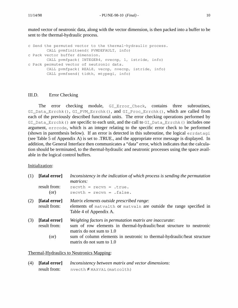
muted vector of neutronic data, along with the vector dimension, is then packed into a buffersent to the thermal-hydraulic process.
c Send the permuted vector to the thermal-hydraulic process. CALL pvmfinitsend( PVMDEFAULT, info)c Pack vector buffer dimension. CALL pvmfpack( INTEGER4, nvecnp, 1, istride, info)c Pack permuted vector of neutronic data. CALL pvmfpack( REAL8, vecnp, nvecnp, istride, info) CALL pvmfsend( tidth, mtypegi, info)
III.D. Error Checking
The error checking module, GI_Error_Check , contains three subroutinesGI_Data_Errchk() , GI_PVM_Errchk() , and GI_Proc_Errchk() , which are called fromeach of the previously described functional units. The error checking operations performGI_Data_Errchk() are specific to each unit, and the call toGI_Data_Errchk() includes oneargument,errcode , which is an integer relating to the specific error check to be perform(shown in parenthesis below). If an error is detected in this subroutine, the logicalerrdatagi(see Table 5 of Appendix A) is set to .TRUE., and the appropriate error message is displayaddition, the General Interface then communicates a “data” error, which indicates that the cation should be terminated, to the thermal-hydraulic and neutronic processes using the spacable in the logical control buffers.
Initialization:
(1) [fatal error] Inconsistency in the indication of which process is sending the permutamatrices:
result from: recvth = recvn = .true.(or) recvth = recvn = .false.
(2) [fatal error] Matrix elements outside prescribed range:result from: elements ofmatvalth or matvaln are outside the range specified i
Table 4 of Appendix A.
(3) [fatal error] Weighting factors in permutation matrix are inaccurate:result from: sum of row elements in thermal-hydraulic/heat structure to neutr
matrix do not sum to 1.0(or) sum of column elements in neutronic to thermal-hydraulic/heat struc
matrix do not sum to 1.0
Thermal-Hydraulics to Neutronics Mapping:
(4) [fatal error] Inconsistency between matrix and vector dimensions:result from: nvecth MAXVAL(matcolth)≠
11/14/98 - PU/NE-98-10 (Final) - 11
ea-
)
nts,r,
hown
. Theneu-
eneralr isr
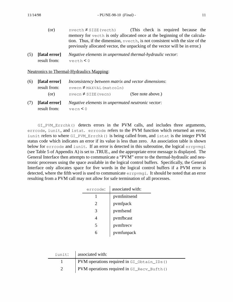
(or) (This check is required because thmemory forvecth is only allocated once at the beginning of the calcultion. Thus, if the dimension,nvecth , is not consistent with the size of thepreviously allocated vector, the unpacking of the vector will be in error.
(5) [fatal error] Negative elements in unpermuted thermal-hydraulic vector:result from:
Neutronics to Thermal-Hydraulics Mapping:
(6) [fatal error] Inconsistency between matrix and vector dimensions:result from:
(or) (See note above.)
(7) [fatal error] Negative elements in unpermuted neutronic vector:result from:
GI_PVM_Errchk() detects errors in the PVM calls, and includes three argumeerrcode , iunit , and istat . errcode refers to the PVM function which returned an erroiunit refers to whereGI_PVM_Errchk() is being called from, andistat is the integer PVMstatus code which indicates an error if its value is less than zero. An association table is sbelow forerrcode andiunit . If an error is detected in this subroutine, the logicalerrpvmgi(see Table 5 of Appendix A) is set to .TRUE., and the appropriate error message is displayedGeneral Interface then attempts to communicate a “PVM” error to the thermal-hydraulic andtronic processes using the space available in the logical control buffers. Specifically, the GInterface only allocates space for five words in the logical control buffers if a PVM errodetected, where the fifth word is used to communicateerrpvmgi . It should be noted that an erroresulting from a PVM call may not allow for safe termination of all processes.
errcode : associated with:
1 pvmfinitsend
2 pvmfpack
3 pvmfsend
4 pvmfbcast
5 pvmftrecv
6 pvmfunpack
iunit : associated with:
1 PVM operations required inGI_Obtain_IDs()
2 PVM operations required inGI_Recv_Bufth()
nvecth SIZE(vecth)≠
vecth 0<
nvecn MAXVAL(matcoln)≠nvecn SIZE(vecn)≠
vecn 0<
11/14/98 - PU/NE-98-10 (Final) - 12
mment,
nt
r ther. Thecom-
pre-ppingf data
ut toslasses:nfor-
sk, and
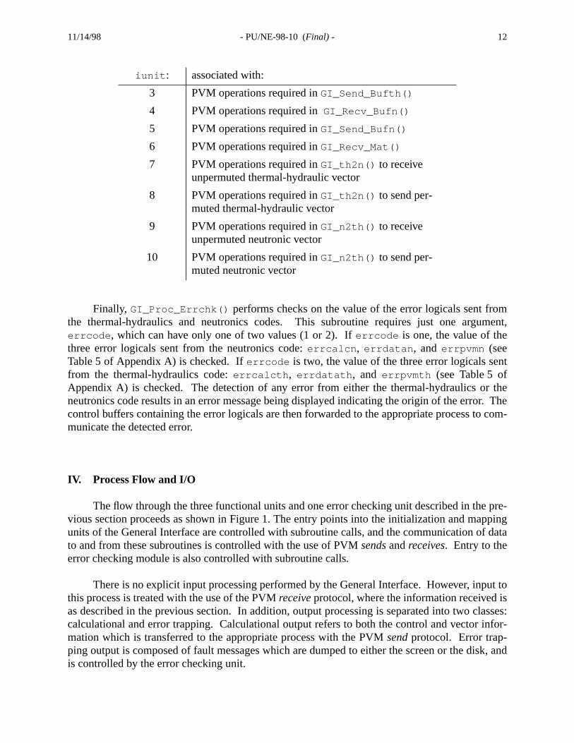
Finally, GI_Proc_Errchk() performs checks on the value of the error logicals sent frothe thermal-hydraulics and neutronics codes. This subroutine requires just one arguerrcode , which can have only one of two values (1 or 2). Iferrcode is one, the value of thethree error logicals sent from the neutronics code:errcalcn , errdatan , and errpvmn (seeTable 5 of Appendix A) is checked. Iferrcode is two, the value of the three error logicals sefrom the thermal-hydraulics code:errcalcth , errdatath , and errpvmth (see Table 5 ofAppendix A) is checked. The detection of any error from either the thermal-hydraulics oneutronics code results in an error message being displayed indicating the origin of the errocontrol buffers containing the error logicals are then forwarded to the appropriate process tomunicate the detected error.
IV. Process Flow and I/O
The flow through the three functional units and one error checking unit described in thevious section proceeds as shown in Figure 1. The entry points into the initialization and maunits of the General Interface are controlled with subroutine calls, and the communication oto and from these subroutines is controlled with the use of PVMsendsandreceives. Entry to theerror checking module is also controlled with subroutine calls.
There is no explicit input processing performed by the General Interface. However, inpthis process is treated with the use of the PVMreceiveprotocol, where the information received ias described in the previous section. In addition, output processing is separated into two ccalculational and error trapping. Calculational output refers to both the control and vector imation which is transferred to the appropriate process with the PVMsendprotocol. Error trap-ping output is composed of fault messages which are dumped to either the screen or the diis controlled by the error checking unit.
3 PVM operations required inGI_Send_Bufth()
4 PVM operations required inGI_Recv_Bufn()
5 PVM operations required inGI_Send_Bufn()
6 PVM operations required inGI_Recv_Mat()
7 PVM operations required inGI_th2n() to receiveunpermuted thermal-hydraulic vector
8 PVM operations required inGI_th2n() to send per-muted thermal-hydraulic vector
9 PVM operations required inGI_n2th() to receiveunpermuted neutronic vector
10 PVM operations required inGI_n2th() to send per-muted neutronic vector
iunit : associated with:

11/14/98 - PU/NE-98-10 (Final) - 13
Figure 1: Calculational Flow for the General Interface Process
done?
ExitProcess
yes
Invoke PVM Process,Obtain Process IDs,
and Initialize Variables
Receive Initial Control Buffer from T/H Process
Extract Information
Send Buffer to Neut. Process
Receive Initial Control Buffer from Neut. Process
Extract Information
Send Buffer to T/H Process
Receive Permutation Matrices from either T/H
or Neut. Process
Initialization
Receive Vector fromT/H Process
Receive T/H Time-Dependent Control Buffer
Perform MAT-VEC
Send Permuted Vectorto Neut. Process
Send T/H Time-Dependent Control Buffer
no
Mapping from Thermal-Hydraulics to Neutronics
Receive Vector fromNeut. Process
Receive Neut. Time-Dependent Control Buffer
Send Permuted Vectorto T/H Process
Send Neut. Time-Dependent Control Buffer
Perform MAT-VEC
Mapping from Neutronics to Thermal-Hydraulics
Perform ErrorChecking
fatalerrors
?
ReturnSuccessful
no
Print Message
ReturnUnsuccessful
yes
Error Checking
Note: Error Checking is called from most routines, and thus the call paths to this module are not shown.

11/14/98 - PU/NE-98-10 (Final) - 14
cula-errores exitc andommu-cribed
o-ple, thee last.tronicdata,rauliculationthe
utines-
cifica-code
nd thes.
withins con-
manag-s. The
Exit handling in the General Interface process is invoked upon receipt of either a caltion- or fault-based signal. A fault-based signal results from a fatal error detected in thechecking module, as discussed in the previous section, and requires that all of the processprematurely. The General Interface communicates the error to both the thermal-hydraulineutronic processes using the next available control buffer send. Once the error has been cnicated to both processes, the General Interface initiates its exit procedure, which is desbelow.
A calculation-based signal (done ) is controlled by the thermal-hydraulic and neutronic prcesses and is transferred to the General Interface through the control buffers. As an examthermal-hydraulic process sends a flag indicating that the current calculation should be thThe interface then performs its calculation and transfers the required information to the neuprocess. At this point, the neutronic process has the ability to reject the thermal-hydraulicand request a new time step calculation, thus resetting the flag sent from the thermal-hydprocess. The neutronic process then sends this flag to the interface, indicating that the calcis not complete. This procedure, which can be inferred from Figure 1, will continue until boththermal-hydraulic and neutronic processes agree on the condition of the flag.
Once termination of the General Interface process has been determined, the subroGI_Clean() andGI_Exit() are called.GI_Clean() frees up any memory not previously deallocated, andGI_Exit() removes the General Interface process from PVM.
The following lines of code depict the overall flow control for the General Interface:
CALL GI_Init() DO 10 WHILE (.NOT. done) CALL GI_th2n() CALL GI_n2th() 10 CONTINUE CALL GI_Clean() CALL GI_Exit()
V. Summary
This document described the software design necessary to satisfy the requirement spetions for the General Interface. The major components outlined here provide the basis fordevelopment and relate to the variable requirements, the design of the functional units, aprocess flow through the interface, which includes the handling of input/output requirement
The General Interface is designed as an independent process, and the incorporationthe framework of the coupled thermal-hydraulics and neutronics code requires both a procestrol and message-passing protocol. The PVM package meets these requirements by bothing the interface task and controlling the communication between the separate processe

11/14/98 - PU/NE-98-10 (Final) - 15
y, as
ctorcode.tricestionalling
ce in
rsity
internal flow control through the functional units of the General Interface is treated logicalldescribed in the previous sections.
The computational requirements for the General Interface consist only of two matrix-vemultiplies, which serve to map property data between the thermal-hydraulic and neutronicThe two mapping units described in the software design accomplish this task using the maand vectors sent from both the thermal-hydraulic and neutronic processes. This computasimplicity in the interface design is the basis for providing the necessary flexibility in coupany thermal-hydraulic code with any neutronic code.
VI. References
1. D. Barber and T. Downar, “Software Requirements Specification for the General Interfathe Coupled Code,” Technical Report, PU/NE-98-8, Purdue University, (1998).
2. Y. Saad, “Numerical Methods for Large Eigenvalue Problems,” Manchester UnivePress, Manchester, UK., pp. 40-41 (1992).

11/14/98 - PU/NE-98-10 (Final) - 16
rface
Appendix A: Variable Description
The following tables provide a description of the variables used by the General Interoutines:
(a) Values less than zero indicate an error has occurred in a PVM call.
Table 1: PVM and Process Control Variables
Name Type Dimension Description Range
done logical 1logical flag: execution is stoppedwhen done=.true.
.true. / .false.
ioutp int*4 1 unit number for output
ntasks int*4 1 number of processes
group char*6 16-character descriptor for thegroup of processes
“procs”
tidgi int*4 1process ID for the General Inter-face module
tidth int*4 1process ID for the Thermal-Hydraulic module
tidn int*4 1process ID for the Neutronic mod-ule
mtypegi int*4 1message tag associated with theGeneral Interface module
mtypeth int*4 1message tag associated with theThermal-Hydraulic module
mtypen int*4 1message tag associated with theNeutronic module
inum int*4 1 instance number in group
istride int*4 1 striding of data in the buffer
info(a) int*4 1 integer error flag for PVM calls
timeout real*4 1int*4 parameter indicating the max# of seconds to wait on a receive
dimbuf int*4 6dimension of each of the 6 datatype-dependent control buffers, inorder, as shown in Tables 2 and 3
0 i 100< <
i 3=
0 i 232< <
0 i 232< <
0 i 232< <
i 1=
i 2=
i 3=
0 i 2≤ ≤
0 i 232< <
232( )– i 2
32< <
i 600=
0 i 232<≤

11/14/98 - PU/NE-98-10 (Final) - 17
(a) Used for both initial and time-dependent control information
Table 2: Thermal-Hydraulic Data and Control Buffers
Name Type Dimension Description Range
cbufth(a) char*6 dimbuf(1)control buffer of 6-characterwords
N/A
lbufth(a) logical dimbuf(2)control buffer of logicalwords
.true. / .false.
i2bufth(a) int*2 dimbuf(3)control buffer of 16 bit inte-ger words
i4bufth(a) int*4 dimbuf(4)control buffer of 32 bit inte-ger words
r4bufth(a) real*4 dimbuf(5)control buffer of 32 bit float-ing point words
r8bufth(a) real*8 dimbuf(6)control buffer of 64 bit float-ing point words
recvth logical 1
a value of .true. indicatesthat both permutation matri-ces are sent from the ther-mal-hydraulic process
.true. / .false.
nvecth int*4 1dimension of vecth receivedfrom thermal-hydraulic pro-cess
vecth real*8 nvecthvector of space-dependentthermal-hydraulic and heatstructure data
nvecthp int*4 1dimension of vecthp sent toneutronic process
vecthp real*8 nvecthppermuted vector of space-dependent thermal-hydrau-lic and heat structure data
216( )– i 2
16< <
232( )– i 2
32< <
1038( )– x 10
38< <
10308( )– x 10
308< <
0 i 232< <
0 x≤ 10308<
0 i 232< <
0 x≤ 10308<

11/14/98 - PU/NE-98-10 (Final) - 18
(a) Used for both initial and time-dependent control information
Table 3: Neutronic Data and Control Buffers
Name Type Dimension Description Range
cbufn(a) char*6 dimbuf(1)control buffer of 6-characterwords
N/A
lbufn(a) logical dimbuf(2)control buffer of logicalwords
.true. / .false.
i2bufn(a) int*2 dimbuf(3)control buffer of 16 bit inte-ger words
i4bufn(a) int*4 dimbuf(4)control buffer of 32 bit inte-ger words
r4bufn(a) real*4 dimbuf(5)control buffer of 32 bit float-ing point words
r8bufn(a) real*8 dimbuf(6)control buffer of 64 bit float-ing point words
recvn logical 1
a value of .true. indicatesthat both permutation matri-ces are sent from the neu-tronic process
.true. / .false.
nvecn int*4 1dimension of vecn receivedfrom neutronic process
vecn real*8 nvecnvector of space-dependentneutronic data
nvecnp int*4 1dimension of vecnp sent tothermal-hydraulic process
vecnp real*8 nvecnppermuted vector of space-dependent neutronic data
216( )– i 2
16< <
232( )– i 2
32< <
1038( )– x 10
38< <
10308( )– x 10
308< <
0 i 232< <
0 x≤ 10308<
0 i 232< <
0 x≤ 10308<

11/14/98 - PU/NE-98-10 (Final) - 19
Table 4: Variables Associated with the Permutation Matrices
Name Type Dimension Description Range
nmatth int*4 1
dimension of the arraysdescribing the permutationmatrices: matvalth,matrowth, and matcolth.
matvalth real*8 nmatth
non-zero elements in thepermutation matrix used tomap thermal-hydraulic andheat structure data to neu-tronic nodes.
matrowth int*4 nmatthrow number correspondingto each element in matvalth
matcolth int*4 nmatthcolumn number correspond-ing to each element inmatvalth
nmatn int*4 1
dimension of the arraysdescribing the permutationmatrices: matvaln, matrown,matcoln.
matvaln real*8 nmatn
non-zero elements in thepermutation matrix used tomap neutronic data to ther-mal-hydraulic zones andheat structure components.
matrown int*4 nmatnrow number correspondingto each element in matvaln
matcoln int*4 nmatncolumn number correspond-ing to each element inmatvaln
1 i n;≤ ≤n nvecthp*nvecth=
0 x< 1≤
1 i nvecthp≤ ≤
1 j nvecth≤ ≤
1 i n;≤ ≤n nvecnp*nvecn=
0 x< 1≤
1 i nvecnp≤ ≤
1 j nvecn≤ ≤

11/14/98 - PU/NE-98-10 (Final) - 20
Table 5: Variables Associated with the Error Checking
Name Type Dimension Description Range
errdatagi logical 1indication of a data error inthe General Interface
.true. / .false.
errpvmgi logical 1indication of a PVM error inthe General Interface
.true. / .false.
errinit logical 1
indication of General Inter-face error (errdatagi .or.errpvmgi) in the Initializa-tion functional unit
.true. / .false.
errth2n logical 1
indication of General Inter-face error (errdatagi .or.errpvmgi) in the Thermal-Hydraulic to Neutronic unit
.true. / .false.
errn2th logical 1
indication of General Inter-face error (errdatagi .or.errpvmgi) in the Neutronicto Thermal-Hydraulic unit
.true. / .false.
errcalcth logical 1indication of a calculationerror in the Thermal-Hydraulics code
.true. / .false.
errdatath logical 1indication of a data error inthe T/H-specific data maproutine
.true. / .false.
errpvmth logical 1indication of a PVM error inthe T/H-specific data maproutine
.true. / .false.
errth logical 1indication of error on T/Hside (errcalcth .or. errdatath.or. errpvmth)
.true. / .false.
errcalcn logical 1indication of a calculationerror in the Neutronics code
.true. / .false.
errdatan logical 1indication of a data error inthe Neutronic-specific datamap routine
.true. / .false.

11/14/98 - PU/NE-98-10 (Final) - 21
errpvmn logical 1indication of a PVM error inthe Neutronic-specific datamap routine
.true. / .false.
errn logical 1indication of error on Neu-tronics side (errcalcn .or. err-datan .or. errpvmn)
.true. / .false.
Table 5: Variables Associated with the Error Checking

11/14/98 - PU/NE-98-10 (Final) - 22
Appendix B: Subroutine Report
Subroutines Deleted:
none
Subroutines Added:
Main GI: Driver for the General Interface.Uses Modules: GI_Var_Decl, GI_Time_Calc
Contains Subroutines:Subroutine GI_Init(): Controls the Initialization func-
tional unit.Uses Module: GI_Init_Calc
Subroutine GI_Clean(): Frees up memory for arrays not pre-viously de-allocated.
Subroutine GI_Exit(): Removes General Interface processfrom PVM.
Module GI_Init_Calc: Contains the subroutines used during the ini-tialization stage.Uses Module: GI_Var_Decl, GI_Error_Check
Contains Subroutines:Subroutine GI_Obtain_IDs(): Establishes communication with
the thermal-hydraulic and neutronic processes.
Subroutine GI_Buf_Init(): Communicates initial controlbuffers between the thermal-hydraulic and neutronicprocesses.Uses Module: GI_Comm_Buf
Subroutine GI_Recv_Mat(): Receives the permutation matri-ces from either the thermal-hydraulic or neutronic pro-cess.

11/14/98 - PU/NE-98-10 (Final) - 23
Module GI_Time_Calc: Contains the subroutines used for the time-dependent data mapping.Uses Module: GI_Var_Decl, GI_Error_Check
Contains Subroutines:Subroutine GI_th2n(): Communicates thermal-hydraulic con-
trol buffer to neutronic process and maps thermal-hydraulic data to the neutronic problem domain.Uses Module: GI_Comm_Buf
Subroutine GI_n2th(): Communicates neutronic controlbuffer to thermal-hydraulic process and maps neutronicdata to the thermal-hydraulic problem domain.Uses Module: GI_Comm_Buf
Module GI_Comm_Buf: Contains the subroutines used to communicatecontrol buffers between the thermal-hydraulic and neutronicprocesses.Uses Module: GI_Var_Decl, GI_Error_Check
Contains Subroutines:Subroutine GI_Recv_Bufth(): Receive thermal-hydraulic con-
trol buffer.
Subroutine GI_Send_Bufth(): Send thermal-hydraulic controlbuffer to neutronic process.
Subroutine GI_Recv_Bufn(): Receive neutronic controlbuffer.
Subroutine GI_Send_Bufn(): Send neutronic control bufferto thermal-hydraulic process.
Module GI_Error_Check: Contains the subroutines used to performthe error checking for the General Interface.Uses Module: GI_Var_Decl
Contains Subroutines:Subroutine GI_Data_Errchk(): Perform error checking on
data used by General Interface.
Subroutine GI_PVM_Errchk(): Perform error checking on PVMstatus variables.
Subroutine GI_Proc_Errchk(): Check the value of error log-icals sent from the thermal-hydraulic and neutroniccodes.
Module GI_Var_Decl: Declares the variables used by the GeneralInterface routines.
11/14/98 - PU/NE-98-10 (Final) - 24
own.
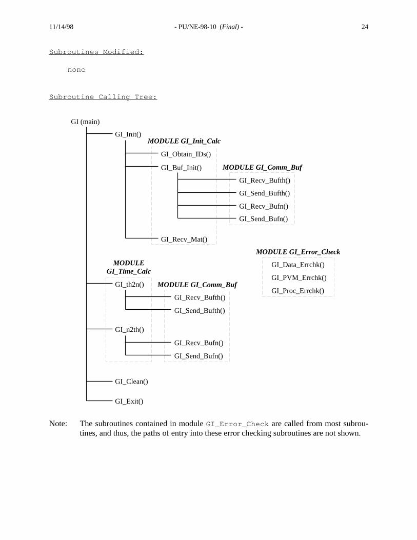
Subroutines Modified:
none
Subroutine Calling Tree:
Note: The subroutines contained in moduleGI_Error_Check are called from most subrou-tines, and thus, the paths of entry into these error checking subroutines are not sh
GI (main)
GI_Init()
GI_th2n()
GI_n2th()
GI_Clean()
GI_Exit()
GI_Obtain_IDs()
GI_Buf_Init()
GI_Recv_Mat()
GI_Recv_Bufth()
GI_Send_Bufth()
GI_Recv_Bufn()
GI_Send_Bufn()
GI_Recv_Bufth()
GI_Send_Bufth()
GI_Recv_Bufn()
GI_Send_Bufn()
MODULE GI_Init_Calc
MODULE GI_Comm_Buf
MODULEGI_Time_Calc
MODULE GI_Comm_Buf
GI_Data_Errchk()
GI_PVM_Errchk()
MODULE GI_Error_Check
GI_Proc_Errchk()