pumping system - carel
TRANSCRIPT

humiFog
User manual
pumping system


�
EN
GL
ISH
humiFog “pumping system” +0�022056� - rel. 1.1 - 29.06.2007
IMPORTANT WARNINGS
BEFORE INSTALLING OR HANDLING THE DEVICE, PLEASE CAREFULLY READ AND FOLLOW THE IN-STRUCTIONS AND THE SAFETY STANDARDS DESCRIBED IN THIS MANUAL AND ILLUSTRATED WITH THE LABELS ON THE UNIT.
This device has been designed to humidify directly in the duct or AHU, using the atomisation rack.
The installation, operation and maintenance operations must be performed in compliance with the instructions provided and with the plates on the labels applied on the inside and outside of the unit.
All other uses and modifications made to the appliance that are not authorised by CAREL S.p.A. are considered incorrect
The environmental conditions must comply with the specified values.
Disconnect the humidifier from the mains power supply before accessing any internal parts.The unit must be installed according to the standards in force.
Liability for injury or damage caused by the incorrect use of the appliance lies exclusively with the user. Please note that the unit contains live electrical devices and high pressure components.
For hygiene reasons, all humiFog systems must be installed with a droplet collection tank underneath the humidification section and with a droplet separator at the end of the humidification section, for the purpose of collecting the particles of water that are not absorbed by the air.
All service and/or maintenance operations must be performed by specialist and qualified personnel who are aware of the necessary precautions.
Disposing of the parts of the humidifier: the humidifier is made up of metal and plastic parts. In reference to European Union directive 2002/96/EC issued on 27 January 200� and the related national legislation, please note that:
1. WEEE cannot be disposed of as municipal waste and such waste must be collected and disposed of separately;
2. the public or private waste collection systems defined by local legislation must be used. In addition, the equipment can be returned to the distributor at the end of its working life when buying new equipment.
�. the equipment may contain hazardous substances: the improper use or incorrect disposal of such may have negative effects on human health and on the environment;
4. the symbol (crossed-out wheeled bin) shown on the product or on the packaging and on the instruc-tion sheet indicates that the equipment has been introduced onto the market after 1� August 2005 and that it must be disposed of separately;
5. in the event of illegal disposal of electrical and electronic waste, the penalties are specified by local waste disposal legislation.
Warranty on materials: 2 years (from the date of production).
Certification: The quality and safety of CAREL products are guaranteed by the Carel ISO 9001 certified design and production system, as well as the mark.
The product must be installed with the earthconnected, using the special yellow-green terminal on the terminal block. Do not use the neutral for the earth connection.

5
EN
GL
ISH
humiFog “pumping system” +0�022056� - rel. 1.1 - 29.06.2007
Content
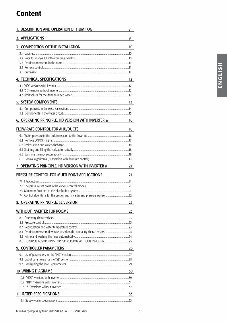
1. DESCRIPTION AND OPERATION OF HUMIFOG 7
2. APPLICATIONS 9
3. COMPOSITION OF THE INSTALLATION 10
�.1 Cabinet ...................................................................................................................................................10�.2 Rack for duct/AHU with atomising nozzles ....................................................................................10�.� Distribution system in the room .......................................................................................................11�.4 Remote control .....................................................................................................................................11�.5 humivisor ...............................................................................................................................................11
4. TECHNICAL SPECIFICATIONS 12
4.1 “HD” versions with inverter ................................................................................................................124.2 “SL” versions without inverter ............................................................................................................124.� Limit values for the demineralised water ........................................................................................12
5. SYSTEM COMPONENTS 13
5.1 Components in the electrical section ..............................................................................................145.2 Components in the water circuit ......................................................................................................15
6. OPERATING PRINCIPLE, HD VERSION WITH INVERTER & 16
FLOW-RATE CONTROL FOR AHU/DUCTS 16
6.1 Water pressure in the rack in relation to the flow-rate ................................................................166.2 Remote ON/OFF signals ....................................................................................................................176.� Recirculation and water discharge .....................................................................................................186.4 Draining and filling the rack automatically ......................................................................................186.5 Washing the rack automatically ........................................................................................................186.6 Control algorithms (HD version with flow-rate control) .............................................................19
7. OPERATING PRINCIPLE, HD VERSION WITH INVERTER & 21
PRESSURE CONTROL FOR MULTI-POINT APPLICATIONS 21
7.1 Introduction ............................................................................................................................................217.2 The pressure set point in the various control modes...................................................................217.� Minimum flow-rate of the distribution system ..............................................................................217.4 Control algorithms for the version with inverter and pressure control ....................................22
8. OPERATING PRINCIPLE, SL VERSION 23
WITHOUT INVERTER FOR ROOMS 23
8.1 Operating characteristics ....................................................................................................................2�8.2 Pressure control....................................................................................................................................2�8.� Recirculation and water temperature control ................................................................................2�8.4 Distribution system flow-rate based on the operating characteristics ...................................248.5 Filling and washing the lines automatically....................................................................................248.6 CONTROL ALGORITHMS FOR “SL” VERSION WITHOUT INVERTER ......................................25
9. CONTROLLER PARAMETERS 26
9.1 List of parameters for the “HD” version..........................................................................................279.2 List of parameters for the “SL” version ............................................................................................289.� Configuring the level � parameters .................................................................................................29
10. WIRING DIAGRAMS 30
10.1 “HD2” versions with inverter ...........................................................................................................�010.2 “HD1” versions with inverter ...........................................................................................................�110.� “SL” versions without inverter .........................................................................................................�2
11. RATED SPECIFICATIONS 33
11.1 Supply water specifications ..............................................................................................................��

EN
GL
ISH
11.2 Cabinet mechanical specifications ..................................................................................................��11.� Water circuit specifications ...............................................................................................................��11.4 Rated electrical specifications ..........................................................................................................�411.5 Rated specifications of the controller for “HD” and “SL” versions ..........................................�411.6 Mechanical specifications of the rack for AHU/ducts .................................................................�411.7 Rated specifications of the room distribution system ................................................................�511.8 Dimensions and weights ..................................................................................................................�5
12. POSITIONING THE CABINET 36
12.1 Preliminary operations .......................................................................................................................�612.2 Water circuit: opening and closing the cabinet ...........................................................................�612.� Water connections ..............................................................................................................................�712.4 Water circuit installation: checklist .................................................................................................�7
13. ELECTRICAL INSTALLATION OF THE CABINET 38
1�.1 Electrical section: opening and closing the cabinet .....................................................................�81�.2 Installation ...........................................................................................................................................�81�.� Power supply ......................................................................................................................................�91�.4 Remote ON/OFF ................................................................................................................................�91�.4 Control signal ......................................................................................................................................401�.5 Cumulative alarm relay ...................................................................................................................411�.6 Solenoid valve connections ..............................................................................................................411�.7 RS485 network .....................................................................................................................................421�.8 Electrical installation: checklist ........................................................................................................4�
14. SWITCHING HUMIFOG ON AND OFF 44
15. CONTROLLER INTERFACE 44
15.1 Display ...................................................................................................................................................4415.2 Buttons ..................................................................................................................................................4415.� Default display ....................................................................................................................................45
16. TESTING AND COMMISSIONING 46
17. SETTING THE SET POINTS 47
17.1 Entering the room probe set point...................................................................................................4717.2 Entering the limit probe set point ....................................................................................................4717.� Entering the discharge pressure set point .....................................................................................48
18. READING THE MEASUREMENTS 49
19. CONFIGURING THE CONTROLLER 50
19.1 Setting the parameters (level �) .......................................................................................................5019.2 Recalling the default parameters ....................................................................................................5019.� Network communication variables ................................................................................................5119.4 Configuration parameters: checklist ..............................................................................................54
20. CHECKLIST FOR THE HD AND SL VERSIONS 55
21. PREVENTIVE MAINTENANCE 56
21.1 Maintenance parameters ..................................................................................................................5621.2 Preventive maintenance of the water filter ...................................................................................5721.� Preventive maintenance of the pump: checking the oil level ..................................................57
22. TROUBLESHOOTING 58
23. ALARMS 60
2�.1 Types of alarm ......................................................................................................................................602�.2 List of alarms for the HD version ....................................................................................................6025.� List of alarms for the SL version .....................................................................................................60

7
20 - 80 bar BA
1 2
3
4
5
6
7
humivisor
clock
prg
set
resume
built-in terminal
EN
GL
ISH
humiFog “pumping system” +0�022056� - rel. 1.1 - 29.06.2007
1. DESCRIPTION AND OPERATION OF HUMIFOGhumiFog is an adiabatic humidifier that atomises demineralised water using a volumetric pump, without requiring compressed air.
The atomising humidifier is an efficient humidification system that is especially suitable for larger installations, where high flow-rates of water are required without the burden of excessive energy expenditure.
When the humidity value in the environment is less than the desired value, as measured by a probe or external controller, the pump is activated.The water, suitably treated using a reverse osmosis system, is pumped at a pressure of between 20 and 80 bar to the atomising nozzles. These, thanks to their special shape, reduce of the jet of water into a multitude of very fine droplets (10 microns). The atomised water can then easily change state and vaporise. The energy required for this transformation is supplied by the ambient air. For each litre/hour of water that vaporises, in fact, the environment gives up around 690 W of energy. Consequently, there is a decrease in temperature in the environment being humidified, and this process may be useful in many applications (adiabatic cooling).The humiFog unit must be supplied with demineralised water, for the following reasons:• to reduce the introduction into the environment of dust due to the mineral salts contained in the
untreated water;• to minimise the clogging of the nozzles.
humiFog is made up of:1. cabinet, containing the electrical panel and the volumetric pump;2. distribution system with the atomising nozzles, for ducts or for rooms
1 probes2 external controller� cabinet4 wall-mounted atomisers5 rack with atomisation manifolds6 remote control7 humivisor and RS485
When the ambient humidity is less than the desired value, or when called by an external controller, the controller starts the volumetric pump to send the demineralised water to the nozzles.
The water reaches the nozzles at a pressure of 20 to 80 bar, and when passing through the opening of each nozzle (with a maximum diameter of 0.20 mm) is transformed into a fog made up of a billion extremely fine particles that can be easily absorbed by the air (the average diameter of the particles of water is equal to 10-15 µm).Depending on the control algorithm activated, the flow-rate of water is controlled in ON/OFF or modulating mode, according to the humidity measured or the control signal from the external controller.
Fig. 1.a

8
1
3
2
P
70 bar
Q min Q max
1
2
reverseosmosis
1 2 43 5 6 7 1 4 6 5 7
EN
GL
ISH
humiFog “pumping system” +0�022056� - rel. 1.1 - 29.06.2007
• The HD version with inverter can operate in flow-rate or pressure control mode. “Flow-rate control” mode has been designed especially to allow a single pump assembly to supply a
single duct/AHU. In the HD version with “flow-rate control” mode, the flow-rate is modulated continuously (Fig. 1.b).
This involves varying the speed of the pump and controlling the capacity of some branches of the nozzles using the solenoid valves contained in the rack (maximum of 8 solenoid valves, divided into � capacity steps).
The uniformity of atomisation is achieved not only due to the small dimensions of the particles of water, but also using the water distribution rack, as this is especially sized to fit perfectly in the AHU section.
“Pressure control” mode has been designed for using a single pump assembly to supply a series of ducts or rooms (Fig. 1.c): in these systems, the humiFog controller manages the speed of the pump according to the pressure set, increasing the speed if the pressure decreases (opening more branches of the circuit) and decreasing it if the pressure increases (closing one or more branches of the circuit).
With this configuration, the humiFog controller cannot manage the humidity and the water distribution directly: this operation must be handled by an external controller.
• The SL version without inverter has been designed to ensure maximum compatibility with systems of humidification directly into the room, where the distribution system needs to be adapted to the environment being humidified.
The operation of these versions occurs at constant pressure to ensure optimum atomisation of the water, and the total number of nozzles can be divided into a maximum of � control steps (maximum of � capacity control solenoid valves).
Special measures can be adopted to supply a series of rooms or ducts, without however controlling the humidity and managing the distribution system, operations performed by the external controller.
The following diagrams illustrate the typical applications in ducts (Fig. 1.d) or directly in the room (Fig. 1.e).
The ambient humidity is measured by a probe (1) and read by the controller contained in the humiFog pumping system (6).Subsequently, the controller compares the humidity measured in the room against the humidity set point, starting, where necessary, the production of atomised water.The demineralised water produced by the external reverse osmosis system (7) is brought to high pressure by the humiFog pump (6), sent to the manifolds for distribution into the duct or directly into the room (5), and then atomised by the nozzles (4); consequently, the water is separated into billions of extremely fine droplets.As the humidification process is adiabatic, when the droplets evaporate, they humidify and at the same time cool the air.
Duct/AHU installations.Naturally, in the AHU, a droplet separator (2) and a droplet collection basin (�) must always be used.
1 flow-rate Q2 pressure= 25 to 75 bar� demand
1 pressure control2 flow-rate Q
Fig. 1.b
Fig. 1.c
Fig. 1.d Fig. 1.e

9
EN
GL
ISH
humiFog “pumping system” +0�022056� - rel. 1.1 - 29.06.2007
2. APPLICATIONShumiFog is suitable for any application where the air can be humidified adiabatically by the atomisation of demineralised water.The following list includes some of the possible applications of humiFog:• office buildings;• production of microchips;• libraries and museums *;• foodstuff storage rooms ;• clean rooms;• cold rooms and fruit ripening stores;• wine cellars storing wine in barrels;• timber storage rooms;• paper mills;• printing facilities;• photo laboratories;• textiles industries;• tobacco ripening and storage rooms;• ambient cooling.
*: do not supply humiFog using water treated with chemicals that may accelerate the normal ageing process of works of art.
The main advantages deriving from the use of humiFog are listed below:• very low power consumption: on average, just 4 W is enough to atomise 1 kg/h of water! An
isothermal immersed electrode or heater humidifier consumes around 750 W for each kg/hour of steam produced. Therefore, the running costs are around 1% of an equivalent immersed electrode or heater humidifier;
• no compressed air used: this means an external compressor is not required, also saving on the air lines;
• by atomising demineralised water, less mineral dust is introduced into the environment, an insignificant amount compared to an equivalent adiabatic humidifier that uses tap water;
• demineralised water guarantees the best hygiene conditions, especially inside the duct, as low mineral salt content does not lead to the formation of deposits and biofilm for bacteria to reproduce (Legionella, etc.);
• reduced maintenance costs;• humiFog is available in different capacities for high flow-rates;• the distribution system is made-to-measure so as to exploit the entire cross-section of the duct or the
space available in the room; • it is more silent than an equivalent humidifier operating on water/compressed air;• it can be controlled via a RS485 network by a supervisor for PC or Humivisor;• it can be controlled by remote control.
The cooling of the ambient air is implicit, as the humidification process is adiabatic. The particles of atomised water absorb the heat from the surrounding air and are transformed into water vapour: the air temperature decreases, while the humidity of the air increases. The degree of adiabatic cooling depends on both the starting temperature and humidity of the air.

10
UA ppp X Y 2 x y1 2 3 4 5 6
2
1
EN
GL
ISH
humiFog “pumping system” +0�022056� - rel. 1.1 - 29.06.2007
3. COMPOSITION OF THE INSTALLATION
3.1 CabinetBelow are the models of humiFog available (Fig. �.a), based on the following system:
The controller features SIX different control algorithms:• algorithm H2: this is used to modulate the flow-rate with two humidity probes (humidity reading and limit). The built-
in humidity controller is used for this purpose. This is the default mode for AHU and duct installations;• algorithm H1: as for algorithm H2, without the humidity limit probe;• algorithm P2: the flow-rate is modulated based on an external control signal and the production of humidity is
limited by the controller based on the value measured by the limit probe. This is ideal, for example, if humiFog is integrated into a Building Management System that generates a control signal;
• algorithm P1: as for algorithm P2, without the humidity limit probe;• algorithm C: operation in on/off mode and managed by an external voltage-free contact (for example, a
humidistat). The flow-rate may be 0% or 100% of the rated rack flow-rate;• algorithm M: (only for model UA*HD*) controls the discharge pressure by varying the speed of the pump using the inverter, so as to maintain
the pressure at the set point when the water demand downstream of the pump changes.
3.2 Rack for duct/AHU with atomising nozzlesThe rack is made up of:• nozzles;• manifolds, which the nozzles are screwed on to;• solenoid valves, for control in steps;• metal structure that support the components.
The racks are made to measure depending on the size of the humidification section inside the duct and the maximum flow-rate of water atomised. All the components on the rack are made from stainless steel.
The data required to size the rack are as follows:• net internal width, expressed in mm, of the humidification section (min. 558 mm);• net internal height, expressed in mm, of the humidification section (min. 508 mm);• free path available for evaporation, expressed in mm, of the humidification section in the direction of air flow. “Free
path available” refers to the length of the duct downstream of the rack until the end of the humidification section, where the droplet separator must be installed.
The width and the height of the rack vary in steps of 152 mm (or multiples of this value), within the following limits:• width: 558 to 2826 mm;• height: 508 to 2790 mm.As the height and the width of the rack vary by a fixed step, the rack may at times not perfectly cover the cross-section of the duct.
As can be seen from Fig. �.b, to prevent stagnant water, a droplet collection tank (1) must be installed underneath the entire humidification section. A droplet separator (2) must be installed at the end of the humidification section to trap the droplets that are not absorbed in the humidification section.
1 rated flow (capacity)060= 60 kg/h120= 120 kg/h180= 180 kg/h250= 250 kg/h�50= �50 kg/h500= 500 kg/h
2 modulation of the flow-rateH= continuous modulation; S= stepped modulation
� power supplyD= 2�0 Vac single-phase 50-60 HzL= 400 Vac three-phase 50-60 Hz
4 version5 brass versions (standard) or stainless steel versions
(for water with conductivity less than �0 µS):0= parts in brass; 1= parts in stainless steel
6 brass versions (standard) or stainless steel versions(for water with conductivity less than �0 µS):0= parts in brass; 1= parts in stainless steel
Fig. 3.a
Fig. 3.b

11
EN
GL
ISH
humiFog “pumping system” +0�022056� - rel. 1.1 - 29.06.2007
3.3 Distribution system in the roomThe distribution system in the room is made up of manifolds with holes for fitting the nozzles, the nozzles themselves, the capacity control solenoid valves (where featured) and drain solenoid valves, all the water fittings, and the pipes and hoses for connection between the various nozzle manifolds.
3.4 Remote controlThe infrared remote control supplied by Carel is an extremely simple tool for controlling up to 99 humidifiers. Its range of action is around three metres.
The remote control allows the user total access to the humidifier parameters. In addition, to assist the input and modification of the data, access to the main parameters is simplified by dedicated buttons that are clearly identified.
The remote control is an optional device that can be ordered separately. There are two versions available:• code TELUA0I000, with the buttons in Italian;• code TELUA0E000, with the buttons in English.
3.5 humivisorhumivisor is the small and useful supervisor supplied by Carel (order code URT0000000).
Designed specially for wall mounting, humivisor can control, via an RS485 network, up to 4 different humidifiers in a radius of 1 km.
humivisor guarantees the user total control of all the humidifiers by the continuous display of their operating status and any alarms, while also allowing the user to enter and modify the related parameters.
In addition, humivisor features two highly useful functions:• each humidifier can be activated or deactivated manually via humivisor; • a daily timer can be used to set two “on” and two “off” times for each day of the week (the on/off
times are used for all the humidifiers connected).
Fig. 3.c
Fig. 3.d
Fig. 3.e

12
EN
GL
ISH
humiFog “pumping system” +0�022056� - rel. 1.1 - 29.06.2007
4. TECHNICAL SPECIFICATIONS
4.1 “HD” versions with inverterAdiabatic humidifier without compressed air, operating on pressurised demineralised water (20 to 80 bar), made up of:• 1 cabinet, containing:
ontroller with 6 algorithms available (ON/OFF, proportional to signal from external controller or signal from external controller + limit probe, built-in humidity controller + limit probe, discharge pressure control);piston pump (flow-rate 60, 120, 180, 250, �50 or 500 kg/hour, according to the application) (brass if conductivity > �0 µS/cm; stainless steel if conductivity < �0 µS/cm);conductivity sensormanual pressure regulator with pressure gauge at the water inlet (max. 8 bar);two polypropylene water filters in series (5 µm and 1 µm);pressure gauge downstream of the filters;low pressure switch upstream of the pump, set at 1 bar;control bypass valve set at 85 bar;thermostatic valve set at 55 °C;high pressure switch, set at 90 bar;pulsation damper, optional;
• 1 stainless steel water atomisation rack, specially sized to suit the cross-section of the humidification section (all the components in contact with the demineralised water must be guaranteed to support a maximum pressure of 100 bar);
• atomising nozzles mounted on the atomisation rack – with a flow-rate of 2.8 or 4.0 kg/hour, pressure 70 bar – the number and model vary depending on the requirements of the application (guaranteed to support pressures of 100 bar);
• on-off drain solenoid valves mounted on the atomisation rack; the number varies depending on the type of application (guaranteed to 100 bar);
• connection pipes and hoses between the cabinet and the atomisation rack, guaranteed for operation with demineralised water at pressures up to 100 bar (according to the application, rubber hoses and/or stainless steel pipes can be used).
4.2 “SL” versions without inverterAdiabatic humidifier without compressed air, operating on pressurised demineralised water (70 to 75 bar).• Cabinet, containing:
controller with 5 algorithms available (ON/OFF, proportional to signal from external controller or signal from external controller + limit probe, built-in humidity controller + limit probe);piston pump (flow-rates: 60, 120, 180, 250, �50, 500 kg/h according to the application);conductivity sensor;manual pressure regulator with pressure gauge at the inlet (max. 8 bar);polypropylene water filters (two in series, 5 µm and 1 µm respectively);pressure gauge downstream of the filters;low pressure switch upstream of the pump, set at 1 bar;water pressure control valve at the outlet, set at 75 bar;thermal valve set at 55 ºC;minimum discharge pressure switch set at 15 bar;maximum discharge pressure switch set at 90 bar;optional pulsation damper;
• Room distribution system, containingnozzle manifolds with holes for 4 nozzles with delivery on one side or 7 nozzles with delivery on two sides (4 on one side + � on the other side);stainless steel atomising nozzles with a flow-rate of 1.45 or 2.8 kg/h at 70 bar;stainless steel capacity control solenoid valves for 100 bar pressure, where featured;drain solenoid valve at the end of the manifolds, available in brass or stainless steel according to the conductivity of the demineralised water (recommended brass with values > �0 µs/cm, stainless steel for values < �0 µs/cm);centralised drain solenoid valve, available in brass or stainless steel according to the conductivity of the demineralised water (recommended brass with values > �0 µs/cm, stainless steel for values < �0 µs/cm);connection lines between the manifoldsfittings for demineralised water lines, with pressure up to 100 bar (optional);connection lines between humifog and the distribution system for operation on demineralised water, with pressure up to 100 bar (depending on the situation, rubber hoses or steel pipes may be used) (optional).
4.3 Limit values for the demineralised waterThe limit values established for the demineralised water are as follows:• conductivity: max. 50 µS/cm;• total hardness: max. 25 ppm CaCO� (= 25 mg/l CaCO� = 2.5 °fH = 1.4 °dH);• pH = from 6.5 to 8.5;• demineralised water supply pressure: from � to 8 bar (0.�-0.8 MPa).
–
–
–––––––––
–
–––––––––––
–
–––
–
–––

1�
built-in terminal
humivisor
clock
prg
set
resume
O.I.R.O.
1 2 3 4
5 12678
9 10
11
EN
GL
ISH
humiFog “pumping system” +0�022056� - rel. 1.1 - 29.06.2007
5. SYSTEM COMPONENTSThe main components in the system are:1. cabinet, divided into the electrical section (with the controller) and water circuit (with the piston
pump);2. atomisation rack for AHUs / ducts or distribution system for rooms, fitted with solenoid valves and
nozzles;�. humidity probes and/or external controller;4. reverse osmosis system, not supplied by CAREL S.p.A.
The reverse osmosis system is required, as humiFog only operates on demineralised water (the limit values for the water are listed in paragraph 9.1).
1 probe2 external controller� humivisor via RS4854 remote control5 solenoid valve6 nozzle7 pump8 controller9 cabinet10 atomisation rack for AHU / duct11 distribution directly into the room12 droplet separator
Fig. 5.a

14
G
RA
R1 R2 R3 F1 F2 F3 F4
TR
K
1
2
3
7
4
8
5
6
G
RA
R1 R2 R3 R4
QS
F1 F2
TR
K
1
2
8
37
6
4
9
5
F3 F4 F6 F7
TRA
F2F1
F5
R1 R2 R3
RA R NA
TRB
ATTENZIONEALTA TENSIONEDANGERHIGH VOLTAGEVORSICHTHOCHSPANNUNGATTENTIONHAUTE TENSION G
EN
GL
ISH
humiFog “pumping system” +0�022056� - rel. 1.1 - 29.06.2007
5.1 Components in the electrical section
Version UAxxxHD2xx with inverter Versions UAxxxHD1xx with inverter
Key1 controller rear view2 I/O board� inverter4 transformer fuse carrier 5 inverter fuse carrier 6 transformer A7 transformer B8 start and wash relays9 relay for solenoid valves10 terminal block
Key1 controller rear view2 I/O board� inverter4 fuse carrier5 terminal block6 relay for rack valves7 contactor8 transformer
Key1 controller rear view2 I/O board� fuse carrier4 terminal block5 relay for rack valves6 contactor7 motor protector8 transformer9 terminal block 2
Version UAxxxSLxxx without inverter
Fig. 5.b Fig. 5.c
Fig. 5.d

15
LP
1 µ 5 µ
LP1
HP
T
2
3
8
4
5
14
11
10
12
136
1
16
7
9
LP
1 µ 5 µ
T
HP
P
2
3
8
4
5
14
11
10
12
136
1
15
7
9
EN
GL
ISH
humiFog “pumping system” +0�022056� - rel. 1.1 - 29.06.2007
5.2 Components in the water circuit
HD version with inverter SL version without inverter
Key1 1µm filter2 2nd inlet pressure gauge� minimum pressure switch (1 bar)4 inlet valve5 motor6 pulsation damper7 1st inlet pressure gauge8 conductivity sensor9 water inlet10 5 µm filter11 discharge pressure gauge12 piston pump1� maximum pressure switch (95 bar)14 thermostatic valve (6� °C/145 °F)15 pressure transducer16 minimum pressure switch LP1 on “HP” side
Fig. 5.e Fig. 5.f

16
80bar
60
40
20
80bar
60
40
20
80bar
60
40
20
8070
50
30
100
0 20 40 60 80 100 120 140 160 180
bar
kg/h
60
40
20
58% 100%
58%38% 100%
58%38%25% 100%
58%38%25%17% 100%
1
2
3
4
EN
GL
ISH
humiFog “pumping system” +0�022056� - rel. 1.1 - 29.06.2007
6. OPERATING PRINCIPLE, HD VERSION WITH INVERTER &FLOW-RATE CONTROL FOR AHU/DUCTS
humiFog with flow-rate control (b1≤ 3)This features the possibility of controlling production by modulating the speed of the pump. The discharge pressure is maintained within the limits for good atomisation (25 to 75 bar, user parameters) by opening/closing a maximum of 4 independent circuits and using a water bypass set at 75 bar.
The main control cycle features three stages:1. the controller reads the relative humidity from the probe or the control signal from the external
controller and calculates the required flow-rate of water;2. the controller sends the inverter a reference signal that controls the speed of the pump and
consequently the flow-rate of the water;�. finally, the solenoid valves on the rack open or close so as to maintain the water discharge pressure
between the minimum and maximum value.The main control cycle works continuously when the remote ON/OFF contact is closed, but stops immediately, as does the atomisation function, as soon as the remote ON/OFF contact opens.
6.1 Water pressure in the rack in relation to the flow-rateThe flow-rate of water to the rack and the pressure are directly related, depending on the characteristics of the atomising nozzles.The purpose is to control the flow-rate of water to the rack so as to reach the required relative humidity value. This is done by controlling the speed of the pump based on the selected control algorithm (see chap. “Control algorithms”).
6.1.1 Water pressureThe field of operating pressure, set by default in the factory, is 25 to 75 bar, however this can be modified by setting parameters b2 (minimum pressure) and b� (maximum pressure), depending on the profile of the application; b2 can be set to a minimum value of 20 bar, and b� to a maximum value of 80 bar.The operating pressure of the water in the rack must be at least 20 bar, so as to ensure the formation of very fine droplets of water. The pressure of the water is maintained below 80 bar: in fact, above this value there are no significant improvements in the size of the droplets.
6.1.2 Atomisation circuitsTo extend the range the water flow-rates, the racks are fitted with solenoid valves in different configurations, depending on the type of application. humiFog can manage up to four independent atomisation circuits, made up of different horizontal manifolds. In each atomisation circuit, all the solenoid valves open and close at the same time.
There are two types of atomisation circuit:• atomisation circuit that is always open The first atomisation circuit on the rack is connected to the water pump discharge without passing
through any solenoid valves; consequently, when the pump is on, the atomisation circuit is always open and atomising;
• atomisation circuits controlled by solenoid valves For each additional atomisation circuit, all the horizontal manifolds are controlled by a solenoid valve.
All the solenoid valves in the same atomisation circuit are connected in parallel and open/close at the same time. humiFog can manage up to three of these atomisation circuits, with a total of 8 solenoid valves.
The controller manages the opening and the closing of the solenoid valves so as to maintain the discharge pressure within the field of operation, while the flow-rate of water to the rack is modulated by the speed of the pump.
Key1 rack with 1 circuit2 rack with 2 circuits� rack with � circuits4 rack with 4 circuits
The diagram illustrates the ratio between water pressure and flow-rate for racks with different atomisation circuit configurations.
Fig. 6.a

17
80 70
50
30
10 0
bar
60
40
20
kg/h
1
EN
GL
ISH
humiFog “pumping system” +0�022056� - rel. 1.1 - 29.06.2007
6.1.3 Overlap between steps in the atomisation circuitWhen there are at least two atomisation circuits, there is always overlap between two adjacent curves, so as to create an opening/closing hysteresis and avoid the vibration of the valve. The extent of the overlap depends on the sizing of the rack, and cannot be modified by the user.The discharge pressure is maintained within the field b2-b�, as follows:• when the pressure increases to “b�” bar, all the solenoid valves connected to the next atomisation
circuit open (indicated by the white arrows in the following diagram);• when the pressure decreases to “b2” bar, all the solenoid valves in the active atomisation circuit close
at the maximum level (indicated by the dark arrows in the following diagram).
The diagram illustrates the ratio between water pressure and flow-rate.
Key:1 overlap
6.1.4 Operating pressure out-of-limitsDuring the working life of the rack, the pressure may fall below the minimum pressure and/or rise above the maximum pressure. This may occur, for example, if there is a leak in the connection between two parts of the rack.In this case, when the valve opens, the discharge pressure may be less than “b2” bar. The opposite situation, pressure above “b�”, may occur if some nozzles are blocked or capacity control solenoid valves are jammed.The controller continuously monitors the discharge pressure and sets off alarm “E7” or alarm “E8”, respectively, as described below.
• Alarm “E8” Activated corresponding to at least one of the following situations: - the discharge pressure rises above “b�+15%” bar. - the discharge pressure falls below “b2-�0%” bar. This alarm is filtered by time: it does not stop the humiFog and is automatically reset by the controller
when the pressure returns within the field b2-b�. The percentages “+15%” and “-�0%” are factory-set values, and cannot be modified by the user.• Alarm “E7” Generated when the discharge pressure is less than “b2-70%”. This is a shutdown alarm filtered by time: it immediately stops the humiFog and, to be reset, the user
must switch humiFog off and on again, as long as discharge pressure has returned within the field b2-b�.
For further information on the alarms, see the Maintenance section.
6.2 Remote ON/OFF signalshumiFog accepts two remote ON/OFF signals:• ON/OFF signal from external hardware contact (always active)• ON/OFF signal from supervisor (active only with RS485 network connection)Both the ON/OFF contacts must be ON to allow the operation of the humidifier.
6.2.1 ON/OFF signal from remote hardware contactThe remote ON/OFF signal may derive from any external voltage-free contact or from a series of voltage-free contacts that activated humiFog when there is demand for humidification.Below are some examples of the most common activation contacts:- cfan contact downstream: the contact is closed when the fan is on, open when the fan is off;- cooling coil contact downstream: the contact is closed when the cooling coil is off, open when the coil
is on.
The series connection of one or more external hardware contacts should be made to inputs 7I and 8I on the terminal block.
6.2.2 ON/OFF signal via the serial network (RS485)The ON/OFF signal via the serial network consists of an RS485 control signal sent by an external supervisor, for example humivisor, to digital variable D15 (see paragraph 19.2). There are two possibilities:• ON/OFF signal via the serial network not active (default mode, C7= 0).• ON/OFF signal via the serial network activate (C7= 1). This mode is used, for example, to activate humiFog in certain time bands, using the humivisor clock
function.
Fig. 6.b
18
T
P
HP
P
1
32
4
EN
GL
ISH
humiFog “pumping system” +0�022056� - rel. 1.1 - 29.06.2007
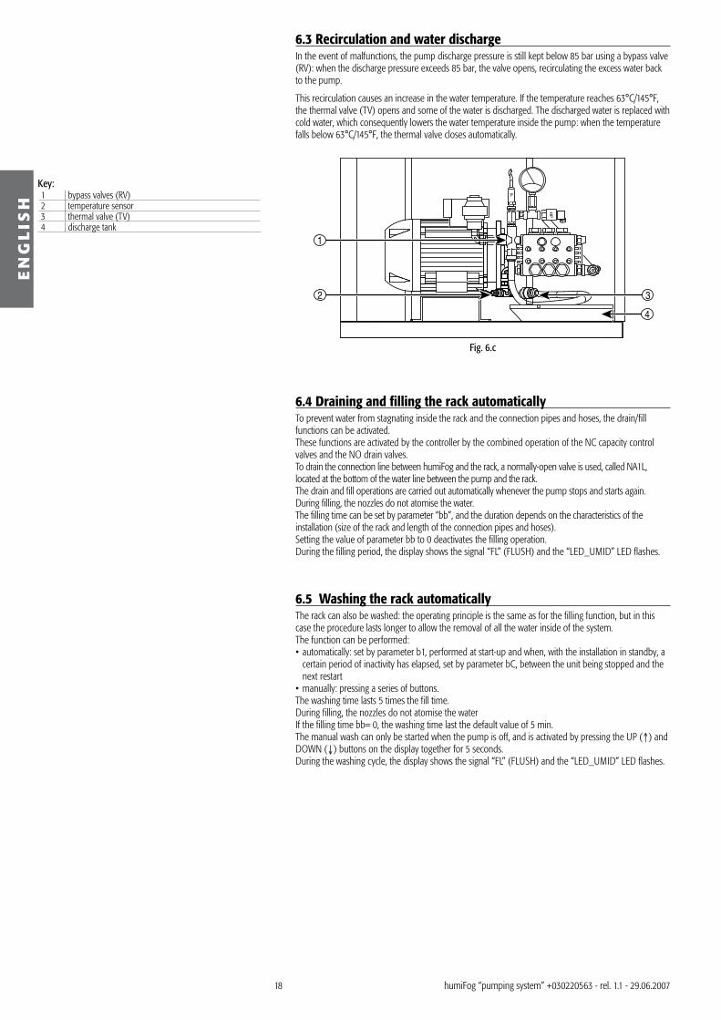
6.3 Recirculation and water dischargeIn the event of malfunctions, the pump discharge pressure is still kept below 85 bar using a bypass valve (RV): when the discharge pressure exceeds 85 bar, the valve opens, recirculating the excess water back to the pump.
This recirculation causes an increase in the water temperature. If the temperature reaches 6�°C/145°F, the thermal valve (TV) opens and some of the water is discharged. The discharged water is replaced with cold water, which consequently lowers the water temperature inside the pump: when the temperature falls below 6�°C/145°F, the thermal valve closes automatically.
Key:1 bypass valves (RV)2 temperature sensor� thermal valve (TV)4 discharge tank
6.4 Draining and filling the rack automaticallyTo prevent water from stagnating inside the rack and the connection pipes and hoses, the drain/fill functions can be activated.These functions are activated by the controller by the combined operation of the NC capacity control valves and the NO drain valves.To drain the connection line between humiFog and the rack, a normally-open valve is used, called NA1L, located at the bottom of the water line between the pump and the rack. The drain and fill operations are carried out automatically whenever the pump stops and starts again. During filling, the nozzles do not atomise the water.The filling time can be set by parameter “bb”, and the duration depends on the characteristics of the installation (size of the rack and length of the connection pipes and hoses).Setting the value of parameter bb to 0 deactivates the filling operation.During the filling period, the display shows the signal “FL” (FLUSH) and the “LED_UMID” LED flashes.
6.5 Washing the rack automaticallyThe rack can also be washed: the operating principle is the same as for the filling function, but in this case the procedure lasts longer to allow the removal of all the water inside of the system.The function can be performed:• automatically: set by parameter b1, performed at start-up and when, with the installation in standby, a
certain period of inactivity has elapsed, set by parameter bC, between the unit being stopped and the next restart
• manually: pressing a series of buttons.The washing time lasts 5 times the fill time.During filling, the nozzles do not atomise the waterIf the filling time bb= 0, the washing time last the default value of 5 min.The manual wash can only be started when the pump is off, and is activated by pressing the UP (↑) and DOWN (↓) buttons on the display together for 5 seconds.During the washing cycle, the display shows the signal “FL” (FLUSH) and the “LED_UMID” LED flashes.
Fig. 6.c

19
100%
P0
b9 10 s
1
5
2
4
4
100%
P0
RF
S
b8
maxmin
1
2
3
EN
GL
ISH
humiFog “pumping system” +0�022056� - rel. 1.1 - 29.06.2007
6.6 Control algorithms (HD version with flow-rate control)Five control algorithms can be selected:• algorithm C:
the flow-rate of water is controlled in on/off mode by an external voltage-free contact (e.g. humidistat);• algorithm P1:
the flow-rate of water is proportional to the control signal from an external controller (e.g. PLC);• algorithm P2 with limit probe:
the flow-rate of water is proportional to the control signal from an external controller (e.g. PLC). The limit probe reduces the flow-rate of water to prevent condensation downstream of the humidification section. This algorithm is suitable for duct/AHU applications;
• algorithm H1: built-in modulating controller connected to a humidity probe and is set as the default control algorithm;
• algorithm H2 with limit probe: built-in modulating controller connected to a humidity probe and a limit probe. The limit probe reduces the flow-rate of water to prevent condensation downstream of the humidification section. This algorithm is suitable for duct/AHU applications.
The different algorithms can be activated by setting parameter A0.
The electrical connections to the humidistats, probes and external controllers are strictly related to the control algorithm selected: for further information on the electrical connections, see chap. 1� “Electrical installation of the cabinet”.
6.6.1 Algorithm “C” (ON/OFF)This algorithm corresponds to A0=0.When the external voltage-free contact (for example, humidistat) closes, the controller starts the pump, increasing its speed to the maximum rack flow-rate (parameter P0) in a time that can be set by the user with parameter b9.When the external contact opens, the controller immediately stops the pump.
Key:1 rack flow-rate2 time� the humidistat closes4 after the humidistat opens5 in the event of shutdown alarms or deactivation
6.6.2 Algorithm “P1” (external controller)This algorithm corresponds to A0=1.The flow-rate of water is proportional to the signal sent by the external controller:
The following electrical signals are accepted from the external controller are (MIN - MAX): 0 to 1 V, 0 to 10 V, 2 to 10 V, 0 to 20 mA, 4 to 20 mA. These can be selected by setting parameter A2.Range of rack flow-rate from b8 to P0: both values are expressed as a % of the rated rack flow-rate and can be changed by the user.An hysteresis has been implemented to avoid quick and continuous on/off actions. “HY” is the code that identifies the amplitude of the hysteresis: the default value is 2% of the MIN - MAX field of the external signal. This CANNOT be modified by the user.
Key:1 rack flow-rate2 external signal� HY= 2% of the min-max range
Fig. 6.d
Fig. 6.e

20
100%
P0
RF
S
b8
maxmin
1
2
3
100%
P0
P6P5
LRF
%UR/rH
b8
100%UR/rH 0%UR %rH
10% of P6
4
5
100%
P0
P1St
b8
100%UR/rH 0%UR %rH
10% of P6
1
2
100%
P0
P1St
RF
%UR/rH
b8
100%UR/rH 0%UR %rH
10% of P1
1
2
EN
GL
ISH
humiFog “pumping system” +0�022056� - rel. 1.1 - 29.06.2007
6.7.3 Algorithm “P2” (with limit probe)This algorithm corresponds to A0=2.The flow-rate of water is proportional to the signal sent by the external controller, and is limited according to the humidity value measured by the limit probe.The algorithm has the following main functions: 1. the controller calculates the water flow-rate in proportion to the external signal (see the diagram
“RACK FLOW-RATE VS. EXTERNAL SIGNAL” Fig. 6.f);2. the controller calculates the limited water flow-rate according to the humidity measured by the limit
probe (see the diagram “LIMITED WATER FLOW-RATE” Fig. 6.g);�. the controller selects the lower value for the water flow-rate and sets the pump speed as a
consequence.
Using the values shown in the following diagrams, the humidity measured by the limit probe corresponds to a “limited” rack flow-rate (LRF) compared to the rack flow-rate (RF), which is proportional to the external signal: the controller selects the LRF value, thus limiting the rack flow-rate and preventing the condensation of the water.
Range of rack flow-rate from b8 to P0: both values are expressed as a % of the rated rack flow-rate and can be changed by the user. The user can select the limit humidity value using parameter P5, at which atomisation is stopped, and the differential P6, which defines the field of linearity of LRF.
Key:1 rack flow-rate2 external signal� HY= 2% of the min-max range4 “limited” rack flow-rate5 % rH measured by the limit probe
6.7.4 Algorithm “H1” (humidity probe)This algorithm corresponds to A0=�.The flow-rate of water is proportional to the difference between the set point St and the current ambient humidity, within a working band (P1).
The rack flow-rate may vary from b8 to P0: both values are expressed as a % of the rated rack flow-rate and can be modified by the user. The set points St and P1 can also be modified.
Key1 rack flow-rate2 ambient %rH
6.7.5 Algorithm “H2” (with limit probe)This algorithm corresponds to A0= 4.The flow-rate of water is proportional to the difference between the set point St and the current ambient humidity, and is limited according to the humidity value measured by the limit probe.The algorithm has the following main functions: 1. the controller calculates the water flow-rate in proportion to (St - % relative humidity) (see the
diagram “RACK FLOW-RATE ACCORDING TO AMBIENT % rH” Fig. 7.f);2. the controller calculates the limited water flow-rate according to the humidity measured by the limit
probe (see the diagram “LIMITED WATER FLOW-RATE”, Fig. 7.d);�. the controller selects the lower value for the water flow-rate and sets the pump speed as a
consequence.
Using the values shown in the following diagrams, the humidity measured by the limit probe corresponds to a “limited” rack flow-rate (LRF) compared to the rack flow-rate (RF), which is proportional to the (St - % relative humidity): the controller selects the LRF value, thus limiting the rack flow-rate and preventing the condensation of the water.
Range of rack flow-rate from b8 to P0: both values are expressed as a % of the rated rack flow-rate and can be changed by the user. The set points St and P1can also be modified.The user can select the limit humidity value using parameter P5, at which atomisation is stopped, and the differential P6, which defines the field of linearity of LRF.
RACK FLOW-RATE vs. EXTERNAL SIGNAL
“LIMITED” RACK FLOW-RATE
Key:1 rack flow-rate2 ambient %rH
RACK FLOW-RATE ACCORDING TO AMBIENT %rH
Fig. 6.f
Fig. 6.g
Fig. 6.h
Fig. 6.i

21
IN
NTC
OUT
1
2
3
EN
GL
ISH
humiFog “pumping system” +0�022056� - rel. 1.1 - 29.06.2007
7. OPERATING PRINCIPLE, HD VERSION WITH INVERTER &PRESSURE CONTROL FOR MULTI-POINT APPLICATIONS
7.1 IntroductionIn pressure control mode, the unit can be used for humidification in multiple air handling units or in separate rooms, being essentially based on maintaining the discharge pressure around a defined pressure set point.
humifog without inverter has been designed specifically for application in rooms.
humiFog with pressure control (b1≥4) has the main purpose of maintaining the discharge pressure constant around a set point. To do this, the speed of the pump is controlled by the inverter. In this case too, the bypass has the task of ensuring that the pressure does not exceed 75 bar.The water circuit downstream of the pump is made completely available to customer, who will provide the control system for opening/closing the circuits in the desired ducts/rooms. The control system, in addition, must provide humiFog, when one or more circuits are opened, the signal for the activation of the humidifier, via an ON/OFF contact connected to the corresponding input.
7.2 The pressure set point in the various control modesIn humiFog with pressure control, parameter “A0” establishes the way that the pressure set point is modified:If A0 < 5 the pressure set point can only be modified by setting parameter “b�”.If A0= 5, the pressure set point can be modified via an external control signal, within the field of variation b2 - b�.
7.3 Minimum flow-rate of the distribution systemFor correct operation, attention must be paid to the minimum flow-rate required from the pumping system by the distribution system; this must not be < 11% of the pump flow-rate.The table below shows the minimum flow-rates of water recommended for each individual model of humiFog.Below these values, the speed of the motor is no longer uniform, and this may affect the correct operation of the system.
minimum flow-rateUA060HD2XX; UA072HD111 6.5 l/h (14.� lb/h)UA120HD2XX; UA144HD111 1� l/h (28.6 lb/h)UA180HD2XX, UA216HD111 20 l/h (44 lb/h)UA250HD2XX, UA�00HD111 �8 l/h (8�.6 lb/h)UA500HD2XX, UA600HD111 55 l/h (121 lb/h)
Tab. 7.a
Key:1 diagram of the bypass circuit2 pump� thermostatic valve
Fig. 7.a

22
Max
100%
b3
min
5% 5%
1
2
100%
100%
b3
“P6”
“P6”/10
1
2
100%
100%
b3
“P1” St
“P1”/10
1
2
EN
GL
ISH
humiFog “pumping system” +0�022056� - rel. 1.1 - 29.06.2007
7.4 Control algorithms for the version with inverter and pressure controlThere are 5 types of control mode (parameter “A0”).
7.4.1 Algorithm “C” (ON/OFF Fig. 7.b)This algorithm corresponds to A0= 0.When the external voltage-free contact (for example, a humidistat) closes, the controller starts the pump, increasing its speed until reaching and maintaining the pressure value set for parameter b�. When the external contact opens, the controller immediately stops the pump.
7.4.2 Algorithm “P1” (external controller Fig. 7.b)This algorithm corresponds to A0=1: proportional (slave).When the signal from the controller is:• > 10% of the maximum input value, the controller starts the pump, increasing its speed until reaching
and maintaining the pressure value set for parameter b�; • < 5% of the maximum input value, the controller immediately stops the pump.
7.4.3 Algorithm “P2” (external controller with limit probe Figs. 7.b and 7.c)This algorithm corresponds to A0= 2: proportional with outlet limit.When the signal from the external controller is:• > 10% of the maximum input value, the controller starts the pump, increasing its speed until reaching
and maintaining the pressure value set for parameter b�.• < 5% of the maximum input value, the controller immediately stops the pump.
When the limit probe measures a humidity value ≥ value of the set point P6, the controller stops the pump.
7.4.4 Algorithm “H1”(humidity probe)This algorithm corresponds to A0= �: humidity control.When the humidity probe measures humidity in the room that is:• < the set point, the controller starts the pump, increasing its speed until reaching and maintaining the
pressure value set for parameter b�;• ≥ the set point, the controller immediately stops the pump.
7.4.5 Algorithm “H2”(with limit probe)This algorithm corresponds to A0= 4: humidity control with outlet limit.When the probe in the room:• measures humidity less than the set point, the controller starts the pump, increasing its speed until
reaching and maintaining the pressure value set for parameter b�;• measures humidity that corresponds to the set point, the controller immediately stops the pump.When the limit probe measures a humidity value ≥ value of the set point P6, the controller stops the pump.
7.4.6 Algorithm “M” (pressure control)For applications in rooms, the control algorithm A0= 5 is preferable, as it allows the possibility to control the speed of the inverter via a signal from an external controller: this mode, in fact, avoids dripping due to sudden changes in pressure in the high pressure water circuit.This is possible by sending a signal to increase the speed of the inverter and consequently the discharge pressure in the water circuit before opening the solenoid valves in a room, thus preventing dripping due to the sudden decrease in pressure. In the same way, the speed of the inverter can be decreased progressively before closing the solenoid valves in a room, thus preventing dripping due to an excessive increase in pressure in the outlet water circuit.Naturally, the times and values of the signal used to bring forward and delay the pressure value must be established when commissioning the installation, given their direct dependence on the characteristics of the outlet water circuit.The same strategy can be used in multi-duct applications.
Key:1 pressure set point2 input on terminal 5I
Key:1 pressure set point2 input on terminal 1I
Key:1 pressure set point2 input on terminal 5I
Fig. 7.b
Fig. 7.c
Fig. 7.d
2�
T
HP
LP1
1
32
4
EN
GL
ISH
humiFog “pumping system” +0�022056� - rel. 1.1 - 29.06.2007
8. OPERATING PRINCIPLE, SL VERSION WITHOUT INVERTER FOR ROOMS
This version of humiFog has been designed for applications in rooms.The main control cycle of humiFog “SL” without inverter features two stages:1. the controller reads the relative humidity from the probe or the control signal from the external
controller;2. the controller starts the pump and, if present, opens the capacity control solenoid valves according to
the humidity demand.
The main control cycle works continuously when the remote ON/OFF contact is closed, but stops immediately, as does the atomisation function, as soon as the remote ON/OFF contact opens.
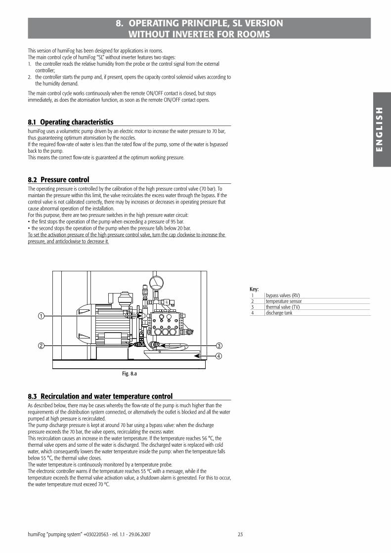
8.1 Operating characteristicshumiFog uses a volumetric pump driven by an electric motor to increase the water pressure to 70 bar, thus guaranteeing optimum atomisation by the nozzles.If the required flow-rate of water is less than the rated flow of the pump, some of the water is bypassed back to the pump.This means the correct flow-rate is guaranteed at the optimum working pressure.
8.2 Pressure controlThe operating pressure is controlled by the calibration of the high pressure control valve (70 bar). To maintain the pressure within this limit, the valve recirculates the excess water through the bypass. If the control valve is not calibrated correctly, there may by increases or decreases in operating pressure that cause abnormal operation of the installation.For this purpose, there are two pressure switches in the high pressure water circuit:• the first stops the operation of the pump when exceeding a pressure of 95 bar.• the second stops the operation of the pump when the pressure falls below 20 bar. To set the activation pressure of the high pressure control valve, turn the cap clockwise to increase the pressure, and anticlockwise to decrease it.
Key:1 bypass valves (RV)2 temperature sensor� thermal valve (TV)4 discharge tank
8.3 Recirculation and water temperature controlAs described below, there may be cases whereby the flow-rate of the pump is much higher than the requirements of the distribution system connected, or alternatively the outlet is blocked and all the water pumped at high pressure is recirculated.The pump discharge pressure is kept at around 70 bar using a bypass valve: when the discharge pressure exceeds the 70 bar, the valve opens, recirculating the excess water.This recirculation causes an increase in the water temperature. If the temperature reaches 56 °C, the thermal valve opens and some of the water is discharged. The discharged water is replaced with cold water, which consequently lowers the water temperature inside the pump: when the temperature falls below 55 °C, the thermal valve closes.The water temperature is continuously monitored by a temperature probe.The electronic controller warns if the temperature reaches 55 ºC with a message, while if the temperature exceeds the thermal valve activation value, a shutdown alarm is generated. For this to occur, the water temperature must exceed 70 ºC.
Fig. 8.a

24
ETV1 NA
ETV1 NC
ETV2 NC
ETV2 NA
ETV3 NC
ETV4 NC
ETV4 NA
ETV3 NA
ETV NA
1
2
3
4
EN
GL
ISH
humiFog “pumping system” +0�022056� - rel. 1.1 - 29.06.2007
8.4 Distribution system flow-rate based on the operating characteristics For the correct operation of the installation, care must be paid to the combination of pump-distribution
system.The distribution system refers to the set of manifolds and nozzles used to distribute the atomised water.The minimum flow-rates according to the type of distribution system can be summarised as follows:• distribution in one room with an individual line: min. flow-rate 25% of the pump flow-rate; max.
flow-rate 100% of the pump flow-rate;• distribution in one room with multiple lines: between 2 and 4 lines are possible, activated
according to the humidity demand in the room. The flow-rate in the first line (line with on-off NC solenoid valve) must not be less than 25% of the pump flow-rate; the maximum flow-rate of the entire system must not be more than 100% of the pump flow-rate.
• distribution in multiple rooms or ducts: the maximum is 4 independent rooms, the humidity in each room is not controlled by humiFog but rather by an independent controller that opens/closes the corresponding solenoid valves according to the humidification demand. The minimum flow-rate in each room must not be less than 25% of the pump flow-rate; the maximum flow-rate of the entire system must not be more than 100% of the pump flow-rate.
Key:1 humidistat in area 12 humidistat in area 2� humidistat in area �4 humidistat in area 5
8.5 Filling and washing the lines automaticallyThe filling system is activated by the controller by the combined operation of the on-off valves (where present) and the drain valves on the distribution lines.This procedure is activated automatically whenever the pump starts, to prevent dripping due to the air in the lines.The fill time can be set using parameter bE and the duration depends on the characteristics of the installation.
The lines can also be washed: the operating principle is the same as for the filling function, but in this case the procedure lasts longer to allow the removal of all the water inside of the system.The function can be performed automatically, set by parameter, or manually, by pressing a series of buttons.When automatic washing is set, the function will be performed upon start-up or, when the installation is in standby, the inactivity time, set by parameter b�, has elapsed between the unit being stopped and the following restart.The washing time lasts 5 times the fill time.The manual wash can be activated by pressing the ↑ and ↓ buttons on the display together for 5 seconds.During the filling cycle, the display shows the signal “FL” (FLUSH) and the “LED_UMID” LED flashes.
When commissioning or testing an installation, the fill procedure can be disabled by setting parameter bE to “0”; with this setting, the washing cycle will have a fixed duration of 5 minutes.
Fig. 8.b
Fig. 8.c
Fig. 8.d
25
rH %
100%HY= 2%b7= 3 P0= 100%
1
75%70%
50%45%
25%20%
100%98
4968.6
73.55
1019.7
24.644.2
1
2
6
5
4
3
rH %
100%
P0= 100%
75%
50%
25%
100%50
P1
P1/10
1
2
6
5
4
3
P1/10
P1/10
EN
GL
ISH
humiFog “pumping system” +0�022056� - rel. 1.1 - 29.06.2007
8.6 Control algorithms for “SL” version withount inverter
8.6.1 Algorithm CThis algorithm corresponds to A0= 0.When the external voltage-free contact (for example, a humidistat) closes, the controller starts the pump.When the external contact opens the controller stops the pump.
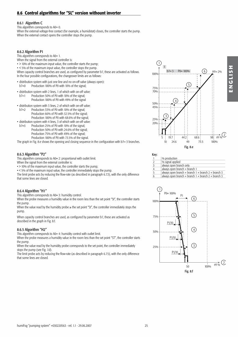
8.6.2 Algorithm P1 This algorithm corresponds to A0= 1.When the signal from the external controller is:• > 10% of the maximum input value, the controller starts the pump;• < 5% of the maximum input value, the controller stops the pump.When capacity control branches are used, as configured by parameter b7, these are activated as follows. In the four possible configurations, the changeover limits are as follows:
• distribution system with just one line and no on-off valve (always open): b7=0 Production 100% of P0 with 10% of the signal;
• distribution system with 2 lines, 1 of which with on-off valve: b7=1 Production 50% of P0 with 10% of the signal; Production 100% of P0 with 49% of the signal
• distribution system with � lines, 2 of which with on-off valve: b7=2 Production ��% of P0 with 10% of the signal; Production 66% of P0 with �2.5% of the signal; Production 100% of P0 with 68.6% of the signal;• distribution system with 4 lines, � of which with on-off valve: b7=� Production 25% of P0 with 10% of the signal; Production 50% of P0 with 24.6% of the signal; Production 75% of P0 with 49% of the signal; Production 100% of P0 with 7�.5% of the signal.The graph in Fig. 8.e shows the opening and closing sequence in the configuration with b7= � branches.
8.6.3 Algorithm “P2”This algorithm corresponds to A0= 2: proportional with outlet limit. When the signal from the external controller is:• > 10% of the maximum input value, the controller starts the pump;• < 5% of the maximum input value, the controller immediately stops the pump.The limit probe acts by reducing the flow-rate (as described in paragraph 6.7.�), with the only difference that some lines are closed.
8.6.4 Algorithm “H1”This algorithm corresponds to A0= �: humidity control.When the probe measures a humidity value in the room less than the set point “St”, the controller starts the pump.When the value read by the humidity probe ≥ the set point “St”, the controller immediately stops the pump.
When capacity control branches are used, as configured by parameter b7, these are activated as described in the graph in Fig. 8.f.
8.6.5 Algorithm “H2”This algorithm corresponds to A0= 4: humidity control with outlet limit.When the probe measures a humidity value in the room less than the set point “ST”, the controller starts the pump.When the value read by the humidity probe corresponds to the set point, the controller immediately stops the pump (see Fig. 7.d).The limit probe acts by reducing the flow-rate (as described in paragraph 6.7.5), with the only difference that some lines are closed.
Key:1 % production2 % signal applied� always open branch only4 always open branch + branch 1 5 always open branch + branch 1 + branch 2 + branch �6 always open branch + branch 1 + branch 2 + branch �
Fig. 8.e
Fig. 8.f

26
EN
GL
ISH
humiFog “pumping system” +0�022056� - rel. 1.1 - 29.06.2007
1
2
3
4
1
2
3
4
A0= 0 A0= 1 A0= 2 A0=3 A0= 4 A0= 5A0 A0 A0 A0 A0 A0A1 A1 A1 A1 A1 A1
A2 A2 A2 A2 A2A� A�A4 A4A5 A5
A6 A6A7 A7A8 A8A9 A9
b1 b1 b1 b1 b1b2 b2 b2 b2 b2 b2b� b� b� b� b� b�b4 b4 b4 b4 b4b5 b5 b5 b5 b5 b5b6 b6 b6 b6 b6 b6b7 b7 b7 b7 b7b8 b8 b8 b8 b8b9 b9 b9 b9 b9 b9ba ba ba ba ba babb bb bb bb bb bbC0 C0 C0 C0 C0 C0C1 C1 C1 C1 C1 C1C2 C2 C2 C2 C2 C2C� C� C� C� C� C�C4 C4 C4 C4 C4 C4C5 C5 C5 C5 C5 C5C6 C6 C6 C6 C6 C6C7 C7 C7 C7 C7 C7P0 P0 P0 P0 P0 P0
P1 P1P2 P2P� P�
P4 P4 P4P5 P5P6 P6P7 P7
d1 d1 d1 d1d2 d2
d� d� d� d� d� d�d4 d4 d4 d4 d4 d4d5 d5 d5 d5 d5 d5d6 d6 d6 d6 d6 d6d7 d7 d7 d7 d7 d7d8 d8 d8 d8 d8 d8d9 d9 d9 d9 d9 d9
St St StTab. 9.a
1
2
3
4
1
2
3
4
A0= 0 A0= 1 A0= 2 A0=3 A0= 4A0 A0 A0 A0 A0A1 A1 A1 A1 A1
A2 A2 A2 A2A� A�A4 A4A5 A5
A6 A6A7 A7A8 A8A9 A9
b1 b1 b1 b1 b1b2 b2 b2 b2 b2b� b� b� b� b�b4 b4 b4 b4 b4b5 b5 b5 b5 b5b6 b6 b6 b6 b6b7 b7 b7 b7 b7b8 b8 b8 b8 b8ba ba ba ba babb bb bb bb bbbc bc bc bc bcbd bd bd bd bdbe be be be bebf bf bf bf bfC0 C0 C0 C0 C0C1 C1 C1 C1 C1C2 C2 C2 C2 C2C� C� C� C� C�C4 C4 C4 C4 C4C5 C5 C5 C5 C5C6 C6 C6 C6 C6C7 C7 C7 C7 C7P0 P0 P0 P0 P0
P1 P1P2 P2P� P�
P4 P4 P4P5 P5P6 P6P7 P7
d1 d1 d1 d1d2 d2
d� d� d� d� d�d4 d4 d4 d4 d4d5 d5 d5 d5 d5d6 d6 d6 d6 d6d7 d7 d7 d7 d7d8 d8 d8 d8 d8d9 d9 d9 d9 d9
St StTab. 9.b
UAxxxHDxxx UAxxxSLxxx
9. CONTROLLER PARAMETERSThe parameters are programmed using the controller interface, the optional remote control or the optional humivisor supervisor.
Table 9.a illustrates the parameters for the UaxxxHDxxx models, accessible based on the control algorithm selected.
Table 9.b illustrates the parameters for the UaxxxSLxxx models, accessible based to the control algorithm selected.
• The value of A0 defines the active control algorithm on the humiFog. The list on the left shows the parameters that are accessible according to the control algorithm selected;
• The accessible parameters can be scrolled using the arrow buttons ↑ and ↓. The list is cyclical, meaning from d9 or St (depending on the control algorithm selected) the user can scroll directly to A0, and vice-versa;
• In reference to the configuration diagram shown in Fig. 9.a, all the accessible parameters can be modified, except for the “dx” parameters, which are read only.
Key:1 control algorithm2 level � parameters (all)� level 2 parameters4 level 1 parameters

27
EN
GL
ISH
humiFog “pumping system” +0�022056� - rel. 1.1 - 29.06.2007
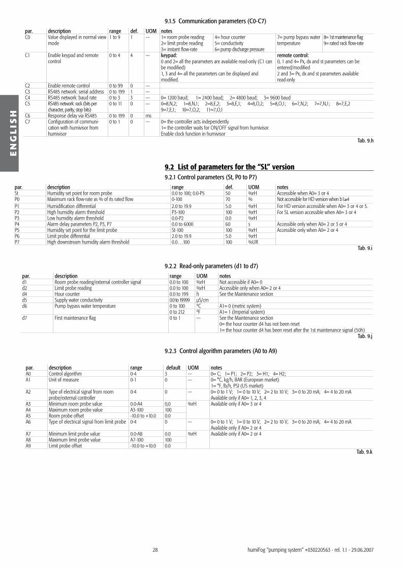
9.1 List of parameters for the “HD” version9.1.1 Control parameters (St, P0 to P7)par. description range def. UOM notesSt Humidity set point for room probe 0.0 to 100; 0.0-P5 50 %rH Accessible when A0= � or 4P0 Maximum rack flow-rate as % of its rated flow B8-100 70 % Not accessible for HD version with b1≥4P1 Humidification differential 2.0 to 19.9 5,0 %rH For HD version accessible when A0= �, 4 or 5
For SL version accessible when A0= � or 4P2 High humidity alarm threshold P�-100 100 %rHP� Low humidity alarm threshold 0.0-P2 0.0 %rHP4 Alarm delay parameters P2, P�, P7 0.0…6000 60 s Accessible only when A0= 2 or � or 4P5 Humidity limit probe set point St-100 100 %rH Accessible only when A0= 2 or 4P6 Limit probe differential 2.0…19.9 5.0 %rHP7 High humidity limit probe alarm threshold 0.0…100 100 %rH
Tab. 9.c
9.1.2 Read-only parameters (d1 to d9) par. description range UOM notesd1 Room probe reading/external controller signal 0.0 to 100 %rH Not accessible if A0= 0d2 Limit probe reading 0.0 to 100 %rH Accessible only when A0= 2 or 4d� Current rack flow-rate 0.0 to 199 10xkg/h (10xlb/h) If b1<4 indicates flow-rate in kg/h, when A1= 0 (when A1=1 lb/h)
Bar / Psi If b1≥4 indicates pressure in bar, when A1=0 (when A1=1 psi)d4 Hour counter 0.0 to 199 h See the Maintenance sectiond5 Supply water conductivity 0.0 to 19999 µS/cmd6 Pump discharge pressure 0.0 to 100 bar A1= 0 (metric system)
0.0 to 1500 Psi Pump discharge pressured7 Pump bypass water temperature 0 to 100 ºC A1= 0 (metric system)
0 to 212 ºF A1= 1 (Imperial system)d8 First maintenance flag 0 to 1 --- 0= the hour counter d4 has not been reset.
1= the hour counter d4 has been reset after the 1st maintenance signal (50h)d9 Rated rack flow-rate 0.0 to 199 10xkg/h; (10xlb/h) A1= 0 (metric system); A1= 1 (Imperial system)
Tab. 9.d
9.1.3 Control algorithm parameters (A0 to A9) par. description range def. UOM notesA0 Control algorithm 0 to 5 � --- 0= C; 1= P1; 2= P2; �= H1; 4= H2; 5= control with external pressure set pointA1 Unit of measure 0 to 1 0 --- 0= °C, kg/h, bar (European market); 1= °F, lb/h, psi (US market)A2 Type of electrical signal from room probe/
external controller0 to 4 0 --- 0= 0 to 1 V; 1= 0 to 10 V; 2= 2 to 10 V; �= 0 to 20 mA; 4= 4 to 20 mA
Not accessible if A0= 0A� Minimum room probe value 0.0-A4 0.0 rH Available only if A0= � or 4 or 5A4 Maximum room probe value A�-100 100A5 Room probe offset -10.0 to +10.0 0.0A6 Type of electrical signal from limit probe 0 to 4 0 --- 0= 0 to 1 V; 1= 0 to 10 V; 2= 2 to 10 V; �= 0 to 20 mA; 4= 4 to 20 mA
Available only if A0= 2 or 4A7 Minimum limit probe value 0.0-A8 0.0 rH Available only if A0= 2 or 4A8 Maximum limit probe value A7-100 100A9 Limit probe offset -10.0 to +10.0 0.0
Tab. 9.e
9.1.4 Parameters relating to the optional devices/functions(b0-bC) par. description range def. UOM notesb1 Special options (recalling the default values has no effect on this
parameter).See the table below for the values of b1.
0 to 7 0
b2 b1<4: minimum branch changeover pressure.b1≥4 lower limit of the pressure set point and A0= 5
10 to �0 25 Bar A1= 0 (metric system)15 to 4� �6 psi A1= 1 (Imperial system)
b� b1<4: maximum branch changeover pressure.b1≥4 and A0<5: represents the pressure set point.b1≥4 and A0=5: upper limit of the pressure set point
0 to 600 75 Bar A1= 0 (metric system)0 to 1�20 109 psi A1= 1(Imperial system)
b4 Rated rack flow-rate 0 to 199 0 kg/hlb/h
A1= 0 (metric system); A1= 1(Imperial system)Not accessible when b1=4
b5 Conductivity pre-alarm threshold 0 to 199; 0k2 to 2k0 100 µS/cmb6 Conductivity alarm threshold 0 to 199; 0k2 to 2k0 200 µS/cmb7 Number of independent branches controlled by solenoid valves 0 to � � Not accessible when b1≥4b8 Minimum rack production 1.0 – P0 14.0 % Not accessible when b1≥4b9 Speed at which the inverter brings production to 100% 0 to 20 0 min 0= �0 s (default); 1= 1 minute; 2= 2 minutesbA Instant “manual” flow-rate of the rack as a % of b4 (b1<4)% of
maximum pump speed (b1≥4)10 to 100 10 % By entering parameter bA, the pump speed immediately adapts to
the selected flow-rate bb Filling time 0 to 60 5 m bb= 0 filling disabled
wash= 5 min.bC Duration of the period of inactivity for wash cycle at restart 1 to 168 6 h 0: activated according to b1 (see the table below)
wash= 5 x bbTab. 9.f
b1= automatic wash
the alarm relay switches with...
“UNIVERSAL HUMIFOG” mode
0 no ...active alarms no1 yes ...active alarms no2 no ...no alarms no� yes ...no alarms no4 no ...active alarms yes
b1= automatic wash
the alarm relay switches with...
“UNIVERSAL HUMIFOG” mode
5 yes ...active alarms yes6 no ...no alarms yes7 yes ...no alarms yes
Tab. 9.g
28
EN
GL
ISH
humiFog “pumping system” +0�022056� - rel. 1.1 - 29.06.2007
9.1.5 Communication parameters (C0-C7)par. description range def. UOM notesC0 Value displayed in normal view
mode1 to 9 1 --- 1= room probe reading
2= limit probe reading�= instant flow-rate
4= hour counter5= conductivity6= pump discharge pressure
7= pump bypass water temperature
8= 1st maintenance flag9= rated rack flow-rate
C1 Enable keypad and remote control
0 to 4 4 --- keypad:0 and 2= all the parameters are available read-only (C1 can be modified)1, � and 4= all the parameters can be displayed and modified.
remote control:0, 1 and 4= Px, dx and st parameters can be entered/modified2 and �= Px, dx and st parameters available read-only
C2 Enable remote control 0 to 99 0 ---C� RS485 network: serial address 0 to 199 1 ---C4 RS485 network: baud rate 0 to � � --- 0= 1200 baud; 1= 2400 baud; 2= 4800 baud; �= 9600 baudC5 RS485 network: rack (bits per
character, parity, stop bits)0 to 11 0 --- 0=8,N,2; 1=8,N,1; 2=8,E,2; �=8,E,1; 4=8,O,2; 5=8,O,1; 6=7,N,2; 7=7,N,1; 8=7,E,2
9=7,E,1; 10=7,O,2; 11=7,O,1C6 Response delay via RS485 0 to 199 0 msC7 Configuration of communi-
cation with humivisor from humivisor
0 to 1 0 --- 0= the controller acts independently 1= the controller waits for ON/OFF signal from humivisor.Enable clock function in humivisor
Tab. 9.h
9.2 List of parameters for the “SL” version9.2.1 Control parameters (St, P0 to P7)
par. description range def. UOM notesSt Humidity set point for room probe 0.0 to 100; 0.0-P5 50 %rH Accessible when A0= � or 4P0 Maximum rack flow-rate as % of its rated flow 0-100 70 % Not accessible for HD version when b1≥4P1 Humidification differential 2.0 to 19.9 5.0 %rH For HD version accessible when A0= � or 4 or 5.
For SL version accessible when A0= � or 4P2 High humidity alarm threshold P�-100 100 %rHP� Low humidity alarm threshold 0.0-P2 0.0 %rHP4 Alarm delay parameters P2, P�, P7 0.0 to 6000 60 s Accessible only when A0= 2 or � or 4P5 Humidity set point for the limit probe St-100 100 %rH Accessible only when A0= 2 or 4P6 Limit probe differential 2.0 to 19.9 5.0 %rHP7 High downstream humidity alarm threshold 0.0…100 100 %UR
Tab. 9.i
9.2.2 Read-only parameters (d1 to d7) par. description range UOM notesd1 Room probe reading/external controller signal 0.0 to 100 %rH Not accessible if A0= 0d2 Limit probe reading 0.0 to 100 %rH Accessible only when A0= 2 or 4d4 Hour counter 0.0 to 199 h See the Maintenance sectiond5 Supply water conductivity 0.0 to 19999 µS/cmd6 Pump bypass water temperature 0 to 100 ºC A1= 0 (metric system)
0 to 212 ºF A1= 1 (Imperial system)d7 First maintenance flag 0 to 1 --- See the Maintenance section
0= the hour counter d4 has not been reset1= the hour counter d4 has been reset after the 1st maintenance signal (50h)
Tab. 9.j
9.2.3 Control algorithm parameters (A0 to A9)
par. description range default UOM notesA0 Control algorithm 0-4 � --- 0= C; 1= P1; 2= P2; �= H1; 4= H2;A1 Unit of measure 0-1 0 --- 0= °C, kg/h, BAR (European market)
1= °F, lb/h, PSI (US market)A2 Type of electrical signal from room
probe/external controller0-4 0 --- 0= 0 to 1 V; 1= 0 to 10 V; 2= 2 to 10 V; �= 0 to 20 mA; 4= 4 to 20 mA
Available only if A0= 1, 2, �, 4A� Minimum room probe value 0.0-A4 0,0 %rH Available only if A0= � or 4A4 Maximum room probe value A�-100 100A5 Room probe offset -10.0 to +10.0 0.0A6 Type of electrical signal from limit probe 0-4 0 --- 0= 0 to 1 V; 1= 0 to 10 V; 2= 2 to 10 V; �= 0 to 20 mA; 4= 4 to 20 mA
Available only if A0= 2 or 4A7 Minimum limit probe value 0.0-A8 0.0 %rH Available only if A0= 2 or 4A8 Maximum limit probe value A7-100 100A9 Limit probe offset -10.0 to +10.0 0.0
Tab. 9.k

29
00
SEL
1
4 5 6 7 11
8
9 10 10
2 2 377 A0
4
1
SEL8
9
4
1
A1 P0 St
EN
GL
ISH
humiFog “pumping system” +0�022056� - rel. 1.1 - 29.06.2007
9.2.4 Parameters relating to the optional devices/functions(b0-bA) par. description range def. UOM notesb1 Special options (recalling the default values has no effect
on this parameter.See the table below for the values of b1.
0 to 5 0
b2 Low discharge pressure alarm delay 1 to 60 � minb� Duration of the period of inactivity for the wash cycle
at restart 0; 6 to 168 24 h Accessible based on b1 (see the table below)
Duration of the wash= 5xbEIf b�= 0 the wash is performed on each restartb4 High temperature pre-alarm threshold - 55 °C A1= 0(metric system)
1�1 °F A1= 1(Imperial system)b5 Conductivity pre-alarm threshold 0 to 199; 0k2 to 2k0 100 µS/cmb6 Conductivity alarm threshold 0 to 199; 0k2 to 2k0 200 µS/cmb7 Number of independent branches controlled by
solenoid valves 0 to � �
bE Filling time 1 to 199 5 min bE= 0 filling disabled; wash= 5 min.bF Time to bring the discharge circuit from 0 to 100% of
required production0 to 190 60 s
bA Editing this parameter forces the production to the value displayed
10 to 100 10 % The value displayed should be considered as a percentage of the flow-rate in the circuit downstream
Tab. 9.lb1= automatic wash the alarm relay switches with...0 no ...active alarms1 no ...no alarms2 --- ---� --- ---4 yes ...active alarms5 yes ...no alarms
Tab. 9.m
9.1.5 Communication parameters (C0-C7)par. description range def. UOM notesC0 Value displayed in normal view
mode1 to 9 1 --- 1= room probe reading
2= limit probe reading�= instant flow-rate4= hour counter
5= conductivity6= pump bypass water temperature
7= 1st maintenance flag8= rated rack flow-rate
C1 Enable keypad and remote control 0 to 4 4 --- keypad:0 and 2= all the parameters are available read-only (C1 can be modified)1, � and 4= all the parameters can be displayed and modified.
remote control:0, 1 and 4= Px, dx and st parameters can be entered/modified2 and �= Px, dx and st parameters available read-only
C2 Enable remote control 0 to 99 0 ---C� RS485 network: serial address 0 to 199 1 ---C4 RS485 network: baud rate 0 to � � --- 0= 1200 baud; 1= 2400 baud; 2= 4800 baud; �= 9600 baudC5 RS485 network: rack (bits per
character, parity, stop bits0 to 11 0 --- 0=8,N,2; 1=8,N,1; 2=8,E,2; �=8,E,1; 4=8,O,2; 5=8,O,1; 6=7,N,2; 7=7,N,1; 8=7,E,2
9=7,E,1; 10=7,O,2; 11=7,O,1C6 Response delay via RS485 0 to 199 0 msC7 Configuration of communication
with humivisor from humivisor0 to 1 0 --- 0= the controller acts independently;
1= the controller waits for ON/OFF signal from humivisor.Enable clock function in humivisor
Tab. 9.n
9.3 Configuring the level 3 parameters
Notes:• to confirm the configuration and exit programming mode at any time, press PRG;• to cancel all the changes to the configuration, wait, without pressing any button, for the display to
return to “normal view” (around 2 min.).
Key:1 start2 normal view� end4 reset the display by pressing PRG, if used
recently5 press PRG and SEL together for 5 seconds and
then release6 set the code “77” using the arrow buttons ↑↓7 confirm the code by pressing and releasing SEL8 select A09 modify the value10 press and release SEL to confirm11 press PRG to confirm all the values and exit
programming mode
Fig. 9.a

�0
G
RA
NC
VFD
T(ntc)
PE
PEN N
L L
F1F3
F2F4
PENLF
F5
CC
PENL
PENL
UVW
PE
S1S2S3S4S5
FSFRFCAC
SC
AM
MAMBMC
M
UVW
3~
1E2E3E
6E5E4E
8I
7I
5I
4I
3K
3H
3I
2K
2H
1H
2G
1G
1J2J3J4J
1B
4B
2B
5B
3B
6B
2C
1C
3C
4C
2D
1D
4D
5D
2A
1A
5A
6A
4A
3A
7A
8A
3D
6D
FLAT
CONNECTION
6I
2I
1K
2C 4C 1C 3C3D 6D 2D 5D 4D 1D 2B5B6B3B 4B 1B 5A2A1A6A7A3A8A4A
1I
RS485
SCHEDA
CONTROLLO
RELAY
ON-OFF
remoto
allarme
+(G)
+(G)
outH
outH
M
M
CH
HT
Sonda
Carel
umidità
relativa
in
mandata
Sonda
Carel
umidità
relativa
ambiente
1.5
KE18CA
PC
LP HP
FLAT
CONNECTION
CONTROL
MODUL
FAN
R4
R2
R3
RNA
G0
G0G0
G0
G0G0
G0G0
NC2
NC3
NC4
NA1
NA2
NA3
NA4
NAL1
NAL
NAL
NAL1
S1
F6F7
F8
24A
24A
2 4A
24A
2 4A
2 4A
1121
3 14144
3 424
14
A1A2
A 1A2
1 121
3 141
1 424
344 4
1 2
A1 A1 A1
A 2 A2 A 2
1 231
11 14
1411
11 1 4
G1
G2
AB
MS
4M
S5
CC
MS
1M
S2
G3
G4
2 4A
24A
G0AG0A
EN
GL
ISH
humiFog “pumping system” +0�022056� - rel. 1.1 - 29.06.2007
10. WIRING DIAGRAMS
10.1 “HD2” versions with inverter
Key: F EMC filterG Main switchF1 Inverter fuseF2 Inverter fuseF� 1A transformer fuse AF4 1A transformer fuse AF5 4A transformer fuse AF6 4A transformer fuse BF7 4A transformer fuse BF8 16A transformer fuse A
CC Controller switchRA Start relayNC Normally closed inlet valveC Conductivity sensorLP Low pressure switchHP High pressure switchT(ntc): Temperature sensorP Pressure transducerR2 Relay for circuit 2R� Relay for circuit �R4 Relay for circuit 4
NAL NO solenoid valve in horizontal manifold
NAL1 NO solenoid valve between humiFog and rack
NC2 NC solenoid valve in circuit 2NC� NC solenoid valve in circuit �NC4 NC solenoid valve in circuit 4NA1 NO solenoid valve in circuit 1NA2 NO solenoid valve in circuit 2NA� NO solenoid valve in circuit �NA4 NO solenoid valve in circuit 4
Fig. 10.a

�1
G
FAN
RA
NC
VFDF
PE
PE N
N
L
L
F1 F3
C2C2 G
0
C3C3 G
0
C4C4 G
0
F2 F4
PE N L
G0
G0
G0
F5
CC
PE N L PE N L U V W PE
S1 S2 S3 S4 S5 FS FR FC ACSC AMMA
MB
MC
M
U V W
3~
6E5E4E1E 2E 3E
8I7I
5I4I
3K
3H
3I
2K
2H1H
2G1G
1J 2J 3J 4J
1B 4B2B 5B3B 6B
2C1C 3C
4C
2D1D 4D
5D
2A1A 5A
6A
4A3A 7A
8A
3D 6D
FLAT CONNECTION
6I
2I
1K
2C4C
1C3C
3D6D
2D5D
4D1D
2B5B
6B3B
4B1B
5A2A
1A6A
7A3A
8A4A
1I
RS485
RELAY
allarme
+(G
)
+(G
)
out H
out HM M
CH HT
1.5 KE18CA
R3
R2
P
C4
C3
C2
T (ntc)
C
LP
HP
R4
K K
ON-OFFremoto
Sonda CARELumidità relativain ambiente
Sonda CARELumidità relativain mandata
SCHEDA CONTROLLO
FLAT CONNECTIONCONTROL
MODUL
EN
GL
ISH
humiFog “pumping system” +0�022056� - rel. 1.1 - 29.06.2007
10.2 “HD1” versions with inverter
Key: F EMC filterG Main switchF1 Inverter fuseF2 Inverter fuseF� Transformer fuse, 2AF4 Transformer fuse, 2AF5 Transformer fuse, 8ACC Controller switchRA Start relayNC Normally closed inlet valveC Conductivity sensorLP Low pressure switchHP High pressure switchT(ntc): Temperature sensorP Pressure transducerR2 Relay for circuit 2R� Relay for circuit �
R4 Relay for circuit 4C2 Solenoid valve in circuit 2C� Solenoid valve in circuit �C4 Solenoid valve in circuit 4
Fig. 10.b

�2
R4
R2
NA4
NA3
NA2
NA
NA1
NC4
NC3
NC2
T (ntc)
LP1
LP
C
HP R3
L1
L1
24
0
M
K
QS
R1
RA
PE
PE
L2
L2 L3
L3
3 ~
G0
G0
G0
G0 G0
G0
G0
G0
G0
G0NC
2
NC3
NC4
NA1
NA2
NA3
NA4
NA
G
F3 F4
6E5E4E1E 2E 3E
8I7I
5I4I
3K
3H
3I
2K
2H1H
2G1G
1J 2J 3J 4J
1B 4B2B 5B3B 6B
2C1C 3C
4C
2D1D 4D
5D
2A1A 5A
6A
4A3A 7A
8A
3D 6D
6I
2I
1K2C
4C1C
3C3D
6D2D
5D4D
1D2B
5B6B
3B4B
1B5A
2A1A
6A7A
3A8A
4A
1I
RELAY
+(G
)
+(G
)
out H
out HM M
CH HT
allarme
F5
CC
FAN NC
K
U V W
FLAT CONNECTION
RS485
ON-OFFremoto
Sonda CARELumidità relativain ambiente
Sonda CARELumidità relativain mandata
SCHEDA CONTROLLO
FLAT CONNECTIONCONTROL
MODUL
EN
GL
ISH
humiFog “pumping system” +0�022056� - rel. 1.1 - 29.06.2007
10.3 “SL” versions without inverter
Key: G Main switchQS Thermal overload switchF� Transformer fuse, 2AF4 Transformer fuse, 2AF5 Transformer fuse, 8ACC Controller switchRA Start relayNC Normally closed inlet valveC Conductivity sensorLP Low pressure switchLP1 Low pressure switch on high pressure sideHP High pressure switchT(ntc): Temperature sensorP Pressure transducerR1 Relay for circuit 1R2 Relay for circuit 2R� Relay for circuit �R4 Relay for circuit 4NC2 Capacity control solenoid valve in the
second circuitNC� Capacity control solenoid valve in the
third circuitNC4 Capacity control solenoid valve in the
fourth circuitNA1 Drain solenoid valve in the first circuitNA2 Drain solenoid valve in the second
circuitNA� Drain solenoid valve in the third circuitNA4 Drain solenoid valve in the fourth circuitNA Main drain solenoid valve
Fig. 10.c

��
EN
GL
ISH
humiFog “pumping system” +0�022056� - rel. 1.1 - 29.06.2007
11. RATED SPECIFICATIONS
11.1 Supply water specificationshumiFog must only be supplied with treated water, based on the limit values listed below. In normal circumstances, this means that the water must be treated using a reverse osmosis system.
**: main values to be considered for all types of installation.
parameter symbol unit of measure limitsmin max
pH (**) pH 6.5 8.5specific conductivity at 20°C (**) σR, 20°C µS/cm 0 50total hardness (**) TH mg/l CaCO� 0 25temporary hardness mg/l CaCO� 0 15total quantity of dissolved solids cR mg/l (*) (*)dry residue at 180°C R180°C mg/l (*) (*)iron + manganese mg/l Fe + Mn 0 0chlorides ppm Cl 0 10silicon dioxide mg/l SiO2 0 1chlorine ions mg/l Cl¯ 0 0calcium sulphate mg/l CaSO4 0 5
Tab. 11.a(*) The values depend on the specific conductivity of the water; normally: cR ≅ 0,65 * σR, 20°C; R180°C ≅ 0,9 * σR, 20°C
IMPORTANT: If the specific conductivity is less than 30 µS/cm, the stainless steel pump should be used.
11.2 Cabinet mechanical specificationsparameter UA060HD2**/SL0**
UA072H111UA120HD2**/SL0**
UA144HD111UA180HD2**/SL0**
UA216HD111UA250HD2**/SL0**
UA300HD111UA350HD2**/SL0**
UA420HD111UA500HD2**/SL0**
UA600HD111weight - packaged (kg/lb) - installed (kg/lb)
91/20078/172
91/20078/172
91/20078/172
99/21886/190
99/21886/190
10�/22690/200
installation floor standingpump oil, type and quantity (kg/lb) SAE 20W-�0WIP IP20operating conditions 1T40 °C (�4T104 °F), 20 to 90 %rH non-condensingstorage conditions 1T50 °C (�4T122 °F), 20 to 90 %rH non-condensing
Tab. 11.b
11.3 Water circuit specifications
11.3.1 “HD2” and “SL” versionsparameter *060HD2*0/SL0*0
*060HD2*1/SL0*1*120HD2*0/SL0*0*120HD2*1/SL0*1
*180HD2*0/SL0*0*180HD2*1/SL0*1
*250HD2*0/SL0*0*250HD2*1/SL0*1
*350HD2*0/SL0*0*350HD2*1/SL0*1
UA500HD2*0/SL0*0UA500HD2*1/SL0*1
limit values see paragraph 11.1maximum flow-rate (l/h - cfh) 60/2.1 120/4.2 180/6.4 250/8.8 �50/12.4 500/17.6pressure (Mpa/Bar/PSI) 0.� to 0.8 / � to 8 / 4� to 116temperature (°C/°F) 1 to 50 / �4 to 122connections G1/2”F (for “HD2*0/SL0*0 versions only)
G1/4”F (for “HD2*1/SL0*1 versions only) G1/2”F (for “HD2*1/SL0*1 versions only)filters in the cabinet 5_m+1_m in series, polypropylene
Tab. 11.c
11.3.2 “HD1” versionsparameter *072HD111 *144HD111 *216HD111 *300HD111 *420HD111 *600HD111limit values see paragraph 11.1maximum flow-rate (l/h - cfh) 72/2.5 144/5.1 216/7.6 �00/10.6 420/14.8 600/21.2pressure (Mpa/Bar/PSI) 0.� to 0.8 / � to 8 / 4� to 116temperature (°C/°F) 1 to 50 / �4 to 122connections NPT1/4”F NPT1/2”F NPT�/4”Ffilters in the cabinet 5 µm+1 µm in series, polypropylene
Tab. 11.d

�4
EN
GL
ISH
humiFog “pumping system” +0�022056� - rel. 1.1 - 29.06.2007
11.3.3 Outlet water from the pump to the distribution system for “HD” and “SL” versionsparameter *060HD2**/SL0**
*072HD1***120HD2**/SL0**
*144HD1***180HD2**/SL0**
*216HD1***250HD2**/SL0**
*300HD1***350HD2**/SL0**
*420HD1***500HD2**/SL0**
*600HD1**pressure (Mpa/Bar/PSI) 2 to 8 / 20 to 80 / 290 to 1160connections G�/8”F (for “HD2**/SL0** versions)
NPT �/8”F (for “HD1** versions)Tab. 11.e
11.3.4 Drain water for all versionsparameter UA***HD***/UA***SL***temperature (°C/°F) 56 to 1�1connections stainless steel pipe, OD 10 mm / 0.4 inch
Tab. 11.f
11.4 Rated electrical specifications
11.4.1 “HD2” and HD1” versionsparameter *060HD2**
*072HD1***120HD2***144HD1**
*180HD2***216HD1**
*250HD2***300HD1**
*350HD2***420HD1**
*500HD2***600HD1**
reference standard class “A” product in compliance with EN55011: 1999-05Vac / phases / Hz 2�0 / 1 / 50 (“HD2” only)
2�0 / 1 / 60 (“HD1” only)power (kW) 0.955 0.955 0.955 1.150 1.150 1.8current (A) 7.0 7.0 7.0 9.2 9.2 12,7
Tab. 11.g
11.4.2 “SL” versionsparameter *060SL0** *120SL0** *180SL0** *250SL0** *350SL0** *500SL0**reference standard class “A” product in compliance with EN55011: 1999-05Vac / phases / Hz 400 / � / 50-60power (kW) 0.950 0.950 0.950 1.10 1.10 1.7current (A) �.0 �.0 �.0 4.7 4.7 7.4
Tab. 11.h
11.5 Rated specifications of the controller for “HD” and “SL” versionsparameter control algorithms C: ON/OFF for all HD/SL versions
P1: proportional with signal from external controller for all HD/SL versionsP2: proportional with signal from external controller and limit probe for all HD/SL versionsH1: built-in controller with room probe for all HD/SL versionsH2: built-in controller with room probe and limit probe for all HD/SL versionsM: constant discharge pressure based on external signal for HD version only
digital inputs remote ON/OFF signal Voltage-free external contact:• Contact closed: humidifier activated. contact impedance max. 50 W, max current 10 mA (generated by humiFog)• Contact open: humidifier deactivated, max ext. voltage �2 Vdc
digital outputs alarm relays SPDT: 250 Vac, 8 A resistive (2 A inductive), 1 C switchingatomisation circuit relays Atomisation circuit relays
analogue inputs room probe / external controller Terminals: 5 I (signal), 6 I (reference).Use shielded cables (connect the shield to terminal 6I).Types of signal supported: 0 to 1 V (default), 0 to 10 V, 2 to 10 V; 0 to 20 mA, 4 to 20 mA (selected from the keypad).Input impedance: - voltage signal: 60 kW -current signal: 50 W
limit probe Terminals: 1I (signal), 2I (reference).Use shielded cables (connect the shield to terminal 2I).Types of signal supported: 0 to 1 V (default), 0 to 10 V, 2 to 10 V; 0 to 20 mA, 4 to 20 mA, (selected from the keypad).Input impedance: - voltage signal: 60 kW - current signal: 50 W
auxiliary power +12 Vdc stabilised (±5%), max. 50 mA: terminal �I�2 V (24 Vac rectified), max. 250 mA: terminal 4I
RS485 4 wire: �2 V (24 Vac rectified), l+, l-, earth max. 1000 m / �200 ftTab. 11.i
11.6 Mechanical specifications of the rack for AHU/ductsmaterial stainless steelwidth (mm/in) 57� to 285� / 22.56 to 112.�2 (minimum step 152 mm/6”)height (mm/in) 5�8 to 2818 / 21.18 to 110.94 (minimum step 152 mm/6”)depth (mm/in) 200 / 7.87 (with horizontal manifold)water inlet connections female G1/4”
Tab. 11.j

�5
375
WO
WD
WI AI AO
CLAF
RV FV LV
TV
112 263255120
20220
770
90
105270 930
860
EN
GL
ISH
humiFog “pumping system” +0�022056� - rel. 1.1 - 29.06.2007
11.7 Rated specifications of the room distribution systemThe room distribution system is made up of a series of manifolds, solenoid valves, nozzles, pipes and various connectors.
component material fittings electrical specifica-tions
notes
Manifolds with 4 holes l=2450 mm hole step 608 mm
Stainless steel F G1/4” --- 4 holes for F 1/8” NPT nozzles
Manifolds with 7 holes l=2450 mm hole step �04 mm
Stainless steel F G1/4” --- 4 holes on R + � on L for F 1/8” NPT nozzles
NC solenoid valve Stainless steel F G1/8”” 24 V 50 Hz 1 central inlet port and 2 side outlet ports for use on R, L or in the centre
NO solenoid valves, brass Brass F G1/4” 24 V 50 Hz for water with conductivity from 50 µS to �0 µS NO solenoid valves, stainless steel Stainless steel F G1/4” 24 V 50 Hz for water with conductivity less than �0 µSPipes Stainless steel OO 10 OO, 1OO OOOOO ---Connectors Stainless steel ---Plugs Stainless steel NPT 1/8”M ---
Nozzles1.45 kg/h model (kg/h / cfh) 1.45 / 0.05 to 70 Bar / 7 MPa / 1010 PSI with 60_m filter2.80 kg/h model (kg/h / cfh) 2.80 / 0.10 to 70 Bar / 7 MPa / 1010 PSI with 60_m filter4 kg/h model (kg/h / cfh) 4 / 0.1� to 70 Bar / 7 MPa / 1010 PSI with 60_m filter
Tab. 11.k
11.8 Dimensions and weightsweight
model kg LBSUA060XXXXX 78 172UA120XXXXX 78 172UA180XXXXX 78 172UA250XXXXX 86 190UA�50XXXXX 86 190UA500XXXXX 90 200
RV – right view FV – front viewLV – left viewTV – top view
Water connections:WI: water inletWO: water outlet to the rackWD: water drain
Air cooling:AI: air inletAO: air outlet
CL: clearance for maintenance
AF: adjustable foot
Fig. 11.a
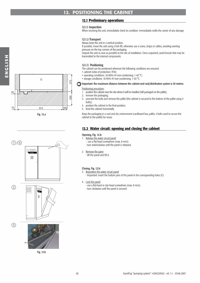
�6
TV
375
300
10097555
45
1
2
F
3
4
EN
GL
ISH
humiFog “pumping system” +0�022056� - rel. 1.1 - 29.06.2007
12. POSITIONING THE CABINET
12.1 Preliminary operations
12.1.1 InspectionWhen receiving the unit, immediately check its condition: immediately notify the carrier of any damage.
12.1.2 TransportAlways keep the unit in a vertical position.If possible, move the unit using a fork lift; otherwise use a crane, straps or cables, avoiding exerting pressure on the top corners of the packaging.Unpack the unit as near as possible to the site of installation. Once unpacked, avoid knocks that may be transmitted to the internal components.
12.1.3 PositioningThe cabinet can be positioned wherever the following conditions are ensured:• cabinet index of protection: IP20;• operating conditions: 20-80% rH non-condensing, 1-40 °C;• storage conditions: 10-90% rH non-condensing, 1-50 °C.
Important: the maximum distance between the cabinet and rack/distribution system is 50 metres.
Positioning procedure:1. position the cabinet near the site where it will be installed (still packaged on the pallet);2. remove the packaging;�. unscrew the bolts and remove the pallet (the cabinet is secured to the bottom of the pallet using 4
bolts);4. position the cabinet in the final position;5. level the cabinet horizontally.
Keep the packaging in a cool and dry environment (cardboard box, pallet, 4 bolts used to secure the cabinet to the pallet) for reuse.
12.2 Water circuit: opening and closing the cabinet
Opening, Fig. 12.b:1. Release the water circuit panel: - use a flat-head screwdriver (max. 8 mm); - turn anticlockwise until the panel is released.
2. Remove the pane: - tilt the panel and lift it.
Closing, Fig. 12.b:�. Reposition the water circuit panel: - Important: insert the bottom pins of the panel in the corresponding holes (F).
4. Lock the panel: - use a flat-head or star-head screwdriver (max. 8 mm); - turn clockwise until the panel is secured.
Fig. 12.a
Fig. 12.b

�7
EN
GL
ISH
humiFog “pumping system” +0�022056� - rel. 1.1 - 29.06.2007
12.3 Water connectionsThe water connections are:• water inlet;• high pressure water outlet to the rack (see ”connecting the cabinet to the rack” in the distribution
system manual);• water drain.
12.3.1 Water installation: instructionsTo simplify installation and maintenance, install a manual valve immediately before connecting the water inlet to the cabinet (this valve is not supplied by CAREL).humiFog only operates on demineralised water, preferably from a reverse osmosis system. The specifications and the limits of the water are described in detail in chap. 11.
1. Open the water circuit (Fig. 12.b part. 1 and 2): • use a flat-head screwdriver, max. 8 mm; • turn the screwdriver anticlockwise to release the panel; • tilt the panel to the outside and lift;
2. Connect the water supply hose (Fig. 12.c): • the connection for the supply hose is F G1/2” (F G1/4” for UD060SL/HDXX1, UD120SL/HDXX1,
UD180SL/HDXX1). • the inside diameter of the supply hose must not be less than 10 mm. • pass the water supply hose through hole “B”.
12.3.2 Water drain connection1 Connect the drain (WD) to the drain system: • use a hose with inside diameter 10 mm, resistant to demineralised water. • connect the hose to the drain connection underneath the cabinet using a hose clampì.N.B.: the hose and the clamp are not supplied by CAREL.
12.3.3 Replacing the top oil plug on the pump1 Replace the top oil plug on the pump: • replace the TOP oil plug (Fig. 12.e, A), used for transport only, with the plug WITH THE VENT HOLE (Fig. 12.e, B) used in normal operation; • keep the plug for future transport.
2 Reposition the front panel on the water circuit and close it.
12.4 Water circuit installation: checklisthumiFog system name: _______________________________________________________
√ Description NotesCabinet levelDistance between cabinet-rack/water distribution system: ≤ 50 m.Water supply connectionWater inlet pressure set at 2 bar (0.2 MPa, 29 PSI)Filters filled with waterDrain connected to the water drain systemPump: oil plug replaced with the plug featuring the ventSupply water within the limit values See the section on “technical specifications”
Date: _______________
Signature: _______________________________________
Fig. 12.c
Fig. 12.d
Fig. 12.e
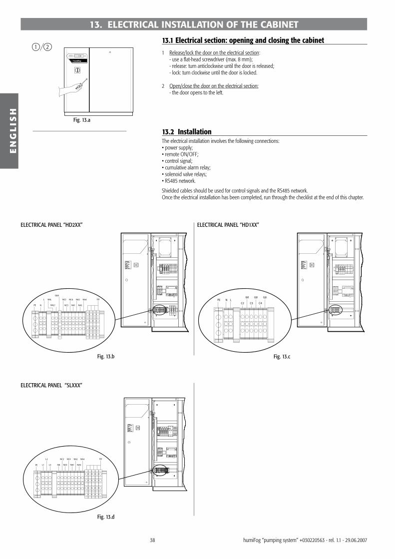
�8
1 2
G
PEG0
N LC2
G0
C3
G0
C4
RA
R1 R2 R3 F1 F2 F3 F4
TR
K
G
TR
K
PE L1
L2
L3 NA
NC2
NC3
NC4
NA1
NA2
NA3
NA4 G0
RA
R1 R2 R3 R4
QS
F1 F2
G
RA
R1 R2 R3 F1 F2 F3 F4
TR
K
PE NAL1
G0A
N
L NAL NC2
NC3
NC4
NA1
NA2
NA3
NA4 G0
R1 R2 R3
EN
GL
ISH
humiFog “pumping system” +0�022056� - rel. 1.1 - 29.06.2007
13. ELECTRICAL INSTALLATION OF THE CABINET
13.1 Electrical section: opening and closing the cabinet
1 Release/lock the door on the electrical section: - use a flat-head screwdriver (max. 8 mm); - release: turn anticlockwise until the door is released; - lock: turn clockwise until the door is locked.
2 Open/close the door on the electrical section: - the door opens to the left.
13.2 InstallationThe electrical installation involves the following connections:• power supply;• remote ON/OFF;• control signal;• cumulative alarm relay;• solenoid valve relays;• RS485 network.
Shielded cables should be used for control signals and the RS485 network. Once the electrical installation has been completed, run through the checklist at the end of this chapter.
ELECTRICAL PANEL “HD2XX” ELECTRICAL PANEL “HD1XX”
ELECTRICAL PANEL “SLXXX”
Fig. 13.a
Fig. 13.b Fig. 13.c
Fig. 13.d

�9
BE
SE
RV FV LV
TV
930
860
55 50 42 42
6015
040
125
75 40 40 40 40 40 100
70
375
230 Vac
C4C3 G0G0C2PE L N G0
PE L1 L3
400 Vac
L3 NA NC2
NC3
NC4
NA1
NA2
NA3
NA4
G0G0
G0G0
G0G0
G0G0
G0G0
7I5I4I3K3H 3I2K2H1H2G
1J2J3J4J
6I2I1K 1I 8I1G
1
2 3
EN
GL
ISH
humiFog “pumping system” +0�022056� - rel. 1.1 - 29.06.2007
To run the cables and connect the controller in the cabinet, proceed as follows:1. open the pre-perforated sections on the left and make the connections using the cable glands
supplied, or alternatively;2. open the pre-perforated sections on the bottom and make the connections using the cable glands
supplied.
RV - right viewFV - front viewLV - left viewBV - bottom viewSE: pre-perforated hole and sections on the left of the cabinet
BE: pre-perforated hole and sections on the bottom of the cabinet
13.3 Power supplyConnect the power cables respectively:For humiFog “UaxxxHDxxx”, 2�0 Vac single-phase 50-60 Hz power supply, � cables L-N-EARTH to be connected to the respective terminals L-N-PE.N.B.: for versions UA500HD2XX and UA600HD1XX, a ferrite is supplied to be applied to the power cable as shown in Fig. 1�.f.N.B.: the power cables must comply with local standards.
For humiFog “UAXXXSLXXX” 400 Vac three-phase 50-60 Hz power supply, 4 cables L1-L2-L�-EARTH to be connected to terminals L1-L2-L�-PE.N.B.: the power cables must comply with local standards.
13.4 Remote ON/OFFRemote ON/OFF contactThe remote ON/OFF contact can be managed using one or a series of external voltage-free contacts, operating as follows:
open: humiFog deactivatedclosed: humiFog activated (atomisation depends on the control signal)
A series of external voltage-free contacts can generate a signal to enable the activation of the humidifier, for example, when the duct/AHU section downstream of the humidifier is ready for atomisation. The remote ON/OFF contact can be connected to:
a fan: contact closed if on;a cooling coil: contact closed if not operating.
Key:1. control board;2. fan operating;�. cooling coil OFF.
••
••
Fig. 13.e
Fig. 13.f
Fig. 13.g
Fig. 13.h

40
7I5I4I3K3H 3I2K2H1H2G
1J2J3J4J
6I2I1K 1I 8I1G
1
2
7I5I4I3K3H 3I2K2H1H2G
1J2J
REFOUT
3J4J
6I2I1K 1I 8I1G
1
2
7I5I4I3K3H 3I2K2H1H2G
1J2J
REFOUT
3J4J
6I2I1K 1I 8I1G
1
2
3
EN
GL
ISH
humiFog “pumping system” +0�022056� - rel. 1.1 - 29.06.2007
13.4 Control signalThe connections of the control input signal depend on the control algorithm. Ask the designer for details of the algorithm.
The control input signal may come from:• a humidistat (ON/OFF);• an external controller;• an active room humidity probe;• an active humidity limit probe.
Note that humiFog provides the power supply to the probes at the following voltages:• +12 Vdc stabilised (CAREL probes);• �2 V (24 Vac rectified).
ON/OFF control algorithm (type “C”)
Connect an external voltage-free contact, e.g. humidistat, to terminals 4I and 5I.
• open= no humidity demand• closed= humidity demand
Key:1. control board;2. external humidistat.
Proportional control algorithm with external controller (type “P1”)
Connect the external controller to terminals 5I and 6I.5l= signal6l= reference
The following signals are accepted:• 0 to 1 V (default setting);• 0 to 10 V;• 2 to 10 V;• 0 to 20 mA;• 4 to 20 mA.
Key:1. control board;2. external controller.
Proportional control algorithm with external controller and limit probe (type “P2”)
EXTERNAL CONTROLLERConnect to terminals 5I and 6I.5l= signal6l= reference
The following signals are accepted:• 0 to 1 V (default setting);• 0 to 10 V;• 2 to 10 V;• 0 to 20 mA;• 4 to 20 mA.
LIMIT PROBECAREL active probes: 1I: humidity signal from the limit probe to the humidifier; 2I: GND supplied by the humidifier to the probe; 4I: +12 Vdc power supply.
Other probes: 1I: humidity signal from the probe to the humidifier; 2I: GND supplied by the humidifier to the probe; �I: �2 V supplied by the humidifier to the probe.
The following signals are accepted:• 0 to 1 V (default setting);• 0 to 10 V;• 2 to 10 V;• 0 to 20 mA; • 4 to 20 mA.
Key:1. control board;2. external controller;�. limit probe
Fig. 13.i
Fig. 13.j
Fig. 13.k

41
7I5I4I3K3H 3I2K2H1H2G
1J2J
Mout H
3J4J
6I2I1K 1I 8I1G
1
2+ (G)
7I5I4I3K3H 3I2K2H1H2G
1J2J
Mout H
3J4J
6I2I1K 1I 8I1G
1
2+ (G)
Mout H 3+ (G)
7I5I4I3K3H 3I2K2H1H2G
1J2J3J4J
6I2I1K 1I 8I1G
1
2
PE N L NAL
NAL1
G0A
G0A
NC2
NC3
NC4
NA1
NA2
NA3
NA4
G0G0
G0G0
G0G0
G0G0
18
9 2
3
4
5
6
7
EN
GL
ISH
humiFog “pumping system” +0�022056� - rel. 1.1 - 29.06.2007
Modulating control with room humidity probe (type “H1”, default setting)
ROOM PROBECAREL active probes: 4I: +12 Vdc supplied by the humidifier to the probe; 5I: humidity signal from the probe to the humidifier; 6I: GND supplied by the humidifier to the probe.
Other probes: �I: �2 V supplied by the humidifier to the probe; 5I: humidity signal from the probe to the humidifier; 6I: GND supplied by the humidifier to the probe.
The following signals are accepted:• 0 to 1 V (default setting);• 0 to 10 V;• 2 to 10 V;• 0 to 20 mA; • 4 to 20 mA.
Modulating control with room humidity probe and limit probe (type “H2”):
ROOM PROBE LIMIT PROBECAREL active probes:
4I: +12 Vdc supplied by the humidifier to the probe; 5I: humidity signal from the probe to the humidifier; 6I: GND supplied by the humidifier to the probe.
CAREL active probes: 1I: humidity signal from the probe to the humidifier; 2I: GND supplied by the humidifier to the probe; 4I: +12 Vdc power supply.
Other probes: �I: �2 V supplied by the humidifier to the probe; 5I: humidity signal from the probe to the humidifier; 6I: GND supplied by the humidifier to the probe.
Other probes: 1I: humidity signal from the probe to the humidifier; 2I: GND supplied by the humidifier to the probe; �I: �2 V supplied by the humidifier to the probe.
The following signals are accepted:• 0 to 1 V (default setting);• 0 to 10 V;• 2 to 10 V;• 0 to 20 mA; • 4 to 20 mA.
13.5 Cumulative alarm relay The alarm relay is activated where one or more alarms are generated.
The alarm relay is an output contact that can, for example, be transferred to an independent supervisory system.
Cumulative alarm contact
1H + 2H: normally-open alarm relay (default setting), activated in the event of alarms;2H + �H: normally-closed alarm relay, deactivated in the event of alarms.
Important: the activation of the alarm relay corresponds to the setting of parameter b1. b1= 0 (default setting), the relay is activated in the event of alarms.
13.6 Solenoid valve connections
13.6.1 humiFog HD2 version with inverter• NAL-GOA connect the drain solenoid valve in the horizontal manifold to these terminals;• NAL1-GOA connect the drain solenoid valve in the humiFog-rack line to these terminals;• NC2-G0 connect the capacity control solenoid valve in the second atomisation circuit to these
terminals;• NC�-G0 connect the capacity control solenoid valve in the third atomisation circuit to these terminals;• NC4-G0 connect the capacity control solenoid valve in the fourth atomisation circuit to these terminals;• NA1-G0 connect the drain solenoid valve in the first atomisation circuit to these terminals;• NA2-G0 connect the drain solenoid valve in the second atomisation circuit to these terminals;• NA�-G0 connect the drain solenoid valve in the third atomisation circuit to these terminals;• NA4-G0 connect the drain solenoid valve in the fourth atomisation circuit to these terminals;
Key:1. control board;2. ambient humidity.
Key:1. Solenoid valve NA4;2. Solenoid valve NA�;�. Solenoid valve NA2;4. Solenoid valve NA1;5. Solenoid valve NC4;
6. Solenoid valve NC�;7. Solenoid valve NC2;8. Solenoid valve NAL1;9. Solenoid valve NAL.
Fig. 13.l
Fig. 13.m
Fig. 13.n
Fig. 13.o
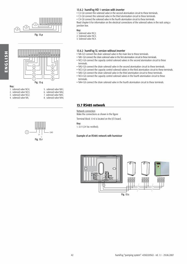
42
GNDL+
L-
1J 2J 3J 4J
1
Rx/Tx+GND
Rx/Tx-
V+V-
1J 2J 3J 4J 1J 2J 3J 4J 1J 2J 3J 4J
12
3
C4C3 G0G0C2PE L N G0
1
2
3
4
8
7
6
5
PE L1 L3 L3 NA NC2
NC3
NC4
NA1
NA2
NA3
NA4
G0G0
G0G0
G0G0
G0G0
G0G0
EN
GL
ISH
humiFog “pumping system” +0�022056� - rel. 1.1 - 29.06.2007
Key:1. solenoid valve NC4; 5. solenoid valve NA1; 2. solenoid valve NC�; 6. solenoid valve NA2; �. solenoid valve NC2; 7. solenoid valve NA�; 4. solenoid valve NA; 8. solenoid valve NA4;
13.6.2 humiFog HD 1 version with inverter• C2-G0 connect the solenoid valve in the second atomisation circuit to these terminals.• C�-G0 connect the solenoid valve in the third atomisation circuit to these terminals. • C4-G0 connect the solenoid valve in the fourth atomisation circuit to these terminals.Read chapter 8 for information on the electrical connections of the solenoid valves in the rack using a junction box.
Key:1. Solenoid valve NC2;2. Solenoid valve NC�;�. Solenoid valve NC4.
13.6.2 humiFog SL version without inverter• NA-GO connect the drain solenoid valve in the main line to these terminals.• NA1-G0 connect the drain solenoid valve in the first atomisation circuit to these terminals.• NC2-G0 connect the capacity control solenoid valves in the second atomisation circuit to these
terminals. • NA2-G0 connect the drain solenoid valve in the second atomisation circuit to these terminals.• NC�-G0 connect the capacity control solenoid valves in the third atomisation circuit to these terminals. • NA�-G0 connect the drain solenoid valve in the third atomisation circuit to these terminals.• NC4-G0 connect the capacity control solenoid valves in the fourth atomisation circuit to these
terminals. • NA4-G0 connect the drain solenoid valve in the fourth atomisation circuit to these terminals.
13.7 RS485 network
Network connectionMake the connections as shown in the figure
Terminal block 1J-4J is located on the I/O board.
Key:1. �2 V (24 Vac rectified);
Example of an RS485 network with humivisorFig. 13.r
Fig. 13.p
Fig. 13.q
Fig. 13.s
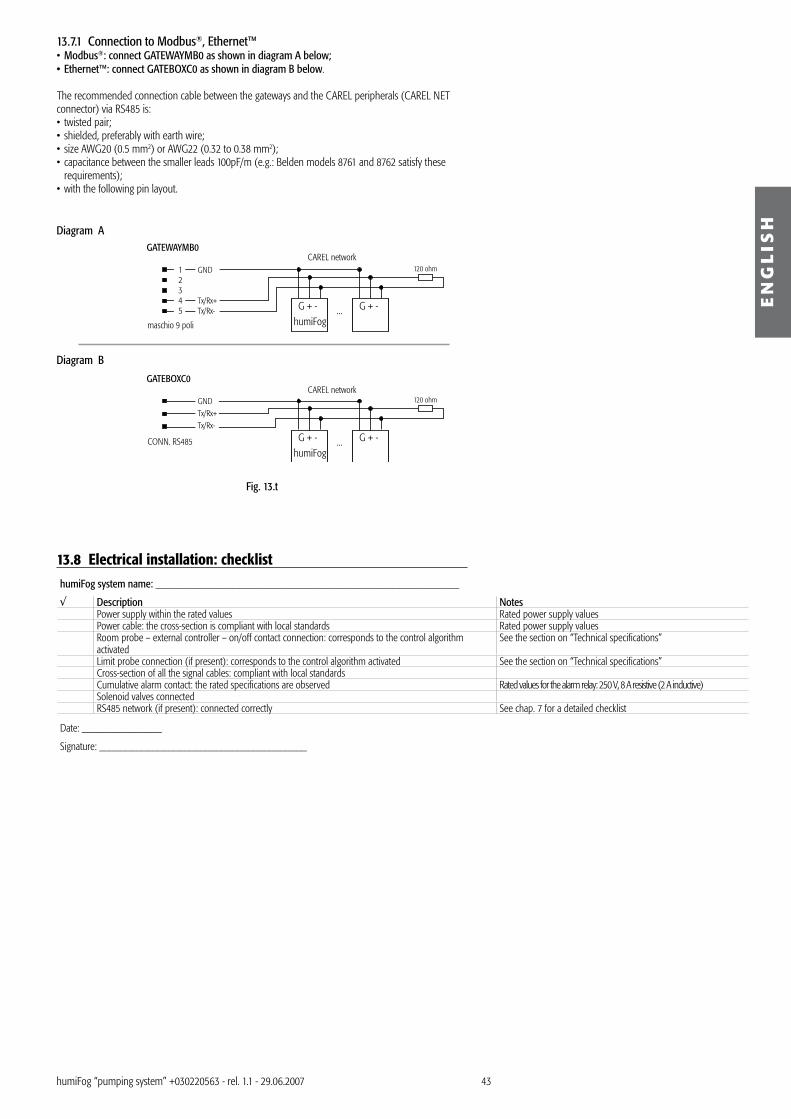
4�
GATEWAYMB0
G + -G + -humiFog
...
G + -G + -humiFog
...
120 ohm
120 ohm
12345
GND
Tx/Rx+Tx/Rx-
maschio 9 poli
GATEBOXC0
GNDTx/Rx+Tx/Rx-
CONN. RS485
CAREL network
CAREL network
EN
GL
ISH
humiFog “pumping system” +0�022056� - rel. 1.1 - 29.06.2007
13.8 Electrical installation: checklisthumiFog system name: _______________________________________________________
√ Description NotesPower supply within the rated values Rated power supply valuesPower cable: the cross-section is compliant with local standards Rated power supply valuesRoom probe – external controller – on/off contact connection: corresponds to the control algorithm activated
See the section on “Technical specifications”
Limit probe connection (if present): corresponds to the control algorithm activated See the section on “Technical specifications”Cross-section of all the signal cables: compliant with local standardsCumulative alarm contact: the rated specifications are observed Rated values for the alarm relay: 250 V, 8 A resistive (2 A inductive)Solenoid valves connectedRS485 network (if present): connected correctly See chap. 7 for a detailed checklist
Date: _______________
Signature: _______________________________________
13.7.1 Connection to Modbus®, Ethernet™• Modbus®: connect GATEWAYMB0 as shown in diagram A below;• Ethernet™: connect GATEBOXC0 as shown in diagram B below.
The recommended connection cable between the gateways and the CAREL peripherals (CAREL NET connector) via RS485 is:• twisted pair;• shielded, preferably with earth wire;• size AWG20 (0.5 mm2) or AWG22 (0.�2 to 0.�8 mm2);• capacitance between the smaller leads 100pF/m (e.g.: Belden models 8761 and 8762 satisfy these
requirements);• with the following pin layout.
Diagram A
Diagram B
Fig. 13.t

44
1o
CS
MS
SEL
resetPRGx1000
alarm line 4
line 3
line 2
1 7 82
3
456
SEL
resetPRGx1000
alarm line 4
line 3
line 2
SEL
resetPRGx1000
alarm line 4
line 3
line 2
EN
GL
ISH
humiFog “pumping system” +0�022056� - rel. 1.1 - 29.06.2007
14. SWITCHING HUMIFOG ON AND OFF1 Switching on:- turn on the main switch (MS) by turning the red knob 90° clockwise;- switch the controller on (CS).
2 Switching off:- switch the controller off (CS);- turn off the main switch (MS).
15. CONTROLLER INTERFACE
15.1 DisplayThe front part of the display features different icons for more direct indications. These icons are associated with a number of segments that turn on depending on the operating status of the humiFog.
reference function1 1st atomisation circuit on:
- steady: pump on;- flashing: the pump will start 1 minute after the demand.
2 2nd atomisation circuit: solenoid valve open� �rd atomisation circuit: solenoid valve open4 4th atomisation circuit: solenoid valve open5 Alarm active (flashing)6 Decimal point 7 Indicates that the value must be multiplied by 10008 Display with 2 and a half digits
Tab. 15.a
15.1.1 Numeric displayThe display shows the numeric values as follows:
0 to 199: The value is represented as shown to the side. For example: 15 is represented as shown in Fig. 15.b. >199: The value is expressed in thousands. For example: 1460 becomes “1•5” as shown in Fig. 15.c.
Note that the rack flow-rate is represented as shown in the figure, with the unit of measure in tens. For example, a rack flow-rate of 2�0 kg/h is displayed as 2�.
15.2 ButtonsThe controller features four buttons that allow complete operation in both normal view mode and in programming mode. As shown in Fig. 15.a, each button has different functions.
button functionPRG to access programming mode, level 2 (press and hold for 5 seconds);
to access programming mode, level � (press and hold together with SEL for 5 seconds);to confirm all the values and exit programming mode;to reset the alarms with manual reset (see the Maintenance section).
SEL to display the selected parameters in programming mode;to confirm the value of the parameters modified temporarily in programming mode;to access programming mode, level 1 (press and hold for � seconds);to access programming mode, level � (press and hold together a PRG for 5 seconds);to display the unit of measure of the parameter in normal view (based on parameter C0).
↑ to move to the next parameter in programming mode;to increase the value of a parameter in programming mode;to display the room probe reading in normal view mode.
↓ to move to the previous parameter in programming mode;to decrease the value of a parameter in programming mode;to display the limit probe reading in normal view mode.
Tab. 15.b
Fig. 14.a
Fig. 15.a
Fig. 15.b Fig. 15.c

45
EN
GL
ISH
humiFog “pumping system” +0�022056� - rel. 1.1 - 29.06.2007
15.3 Default displayThe “default display” is the value normally displayed immediately after the humiFog is started and during the normal operation. In normal view mode, different types of values can be displayed, associated with the operating status of humiFog. In programming mode, to exit and switch to normal view mode, simply press and release PRG.
The normal view depends on:• type of humiFog unit, “HD” with inverter or “SL” without inverter;• the control algorithm used;• the value of the configuration parameter C0;• for “HD” versions with inverter, the operating mode set by parameter B1.Depending on the value of parameter C0, the following values can be displayed innormal view mode:
For “HD” versions with inverter:1. room probe reading / control signal from external controller;2. limit probe reading;�. flow-rate; (not visible in constant pressure mode).4. hour counter;5. conductivity;6. pump water discharge pressure;7. water bypass temperature;8. 1st maintenance flag;9. rated rack flow-rate; (available when b1= 4).
For “SL” versions without inverter:1. room probe reading/control signal from external controller;2. limit probe reading;�. flow-rate: % flow-rate pump, depending on the number of steps set;4. hour counter;5. conductivity;6. water bypass temperature;7. 1st maintenance flag;
The normal view can be set by the user, so as to display different values based on the type of application. By default, the normal view is set as room probe reading / control signal from external controller (corresponding to C0=1).
15.3.1 Displaying the control signal when C0≠1In normal view mode, the control signal, either from an external controller or from a humidity probe, can be displayed very simply by pressing one of the arrow buttons. The table below describes control signal depending on the control algorithm activated.
control algorithm activated instructionsC: ON/OFF control (A0= 0) Signal not available.P1: proportional control with external controller (A0= 1) Press ↑ to display the control signal from the external controller.P2: proportional control with external controller and limit probe (A0= 2) Press ↑ to display the control signal from the external controller.
Press ↑ to display the relative humidity measured by the limit probe.H1: modulating control with one probe (A0= �) Press ↑ to display the relative humidity measured by the room probe.H2: modulating control with two probes (A0= 4) Press ↑ to display the relative humidity measured by the room probe.
Press ↑ to display the relative humidity measured by the limit probe.M: discharge pressure control (b1≥4; present only on models UA*HD*) Press ↑ to display the discharge pressure
Tab. 15.cBefore displaying the desired value, the unit of measure is shown for one second. All the control signals are expressed as a percentage (%).

46
1o
CS
MS
SEL
resetPRGx1000
alarm line 4
line 3
line 2
1
2
3
45
6
7
1
2
34
5
6
7
1
2
3
45
6
7
1
2
34
5
6
7
E
D
SEL
resetPRGx1000
alarm line 4
line 3
line 2
1
2
3
4
5
6
7
8
1
2
3
4
5
6
7
8
1
2
3
4
5
6
7
8
1
2
3
4
5
6
7
8
1
2
3
4
5
6
7
8
EN
GL
ISH
humiFog “pumping system” +0�022056� - rel. 1.1 - 29.06.2007
16. TESTING AND COMMISSIONINGImportant:• if possible, the testing must be performed before installation in the duct /AHU;• during testing, the pump discharge pressure may exceed 75 bar (7.5 MPa).
The purpose of testing is to:• identify any water leaks;• check that the solenoid valves open/close in the correct sequence.
IMPORTANT: the installer should know how to access the 3rd level parameters (see 6.1)
1 Adjust the supply pressure to 2 bar (0.2 MPa, 29 PSI):open the external supply valve;turn the regulator clockwise to increase the pressure or anticlockwise to decrease it, until the inlet pressure reaches 2 bar.
2 Fill the filters with water:make sure that the drain valves on the filter located on the bottom of the filter cap are closed, as shown in the photo (D);press the black button (E) on the filter cap on the right until water is discharged, then release the button;repeat for the filter on the left;dry any water leaks.
3 Switch on humiFog:switch on the main switch MS;switch on the controller (CS).
4 Access parameter bA:during start-up the display shows three dashes; wait until a numeric value is displayed;access parameter bA (see 19.1);important: the pump starts operation;important: the pump discharge pressure may exceed 75 bar;important: the rack atomises the water.
5 Test the rack/water distribution system:increase bA: press the arrow ↑ until the value 100 is displayedcheck for any water leakscheck that the solenoid valves in the rack open/close in the correct sequencereduce bA to 10 using ↑, ↓press PRGswitch off humiFog (first CS then MS)
6 Everything OK?YES: the testing of the rack/water distribution system is completeNO: go to point 5
7 Leaks found? check the water connections:
8 Valves blocked or valves do not open in the correct sequence?check the electrical connections;check the position of the solenoid valves.
9 Repeat the testing sequence starting from point 1.
••
•
•
••
••
•••••
••••••
••
•
••
Fig. 16.c
Fig. 16.d
Fig. 16.a
Fig. 16.b
Fig. 16.e

47
SEL
resetPRGx1000
alarm line 4
line 3
line 2
SEL
resetPRGx1000
alarm line 4
line 3
line 2
SEL
resetPRGx1000
alarm line 4
line 3
line 21
2
3
SEL
resetPRGx1000
alarm line 4
line 3
line 2
SEL
resetPRGx1000
alarm line 4
line 3
line 2
SEL
resetPRGx1000
alarm line 4
line 3
line 2
SEL
resetPRGx1000
alarm line 4
line 3
line 2
SEL
resetPRGx1000
alarm line 4
line 3
line 2
1
2
3
4
5
EN
GL
ISH
humiFog “pumping system” +0�022056� - rel. 1.1 - 29.06.2007
17. SETTING THE SET POINTSTo achieve the required relative humidity level, the set point must be set if humiFog is controlled by a room humidity probe. In addition, a limit probe can be used to ensure that the relative humidity downstream of the rack does not reach the saturation, with the consequent risk of condensation. The characteristics of the set point parameter are shown in the table below.
parameter and description unit of measure
default value range corresponding control algorithm
St: ambient humidity set point % rH 50 0.0-100 H1: modulating control with 1 probe (room probe)0.0-P5 H2: modulating control with 2 probes
P5: limit probe set point % rH 100 St*-100 P2: proportional control with limit probeSt-100 H2: modulating control with 2 probes
b�: (when b1≥4 and A0<5): discharge pressure set point.b� is not a set point if b1<4 or A0= 5 when b1≥4.
bar/PSI 75/109 50…80/72…116
Tab. 17.aSt*= the value can be displayed and/or modified by temporarily setting parameter A0= � or 4.These set points can be modified only when one of the control algorithms shown above is active.
17.1 Entering the room probe set pointImportant: the room probe set point can only be entered and modified if one of the modulating algorithms has been selected (Hx) (A0=� or 4). 1 Access and enter parameter St: • press and release PRG to switch to normal view; • to access parameter St press SEL for � seconds until displaying “St”. Then release SEL. The unit of
measure is displayed briefly; the set point is then displayed.
2 Enter St: • to modify the set point, use the arrows, ↑ or ↓.
3 Exit: • press and release PRG to save the new value and exit the procedure.
17.2 Entering the limit probe set pointImportant: the limit probe set point can only be entered and modified if one of the control algorithms that features a limit probe signal is active (A0=2 or 4).
IMPORTANT: To modify the limit probe set point, set parameter P5. Do not modify any other parameters (for further details on all the parameters, see the section on technical specifications).
1 Access the Px parameters: • press PRG for 5 seconds until displaying P0, then release the button.
2 Move to parameter P5: • to select P5 use the arrows, ↑ or ↓;
3 Access the parameter to be entered: • press and release SEL.
4 Modify the parameter: • To set the parameter, use the arrows, ↑ or ↓.
5 Confirm the new value and exit: • press PRG to confirm the value and exit programming mode.
Fig. 17.a
Fig. 17.b
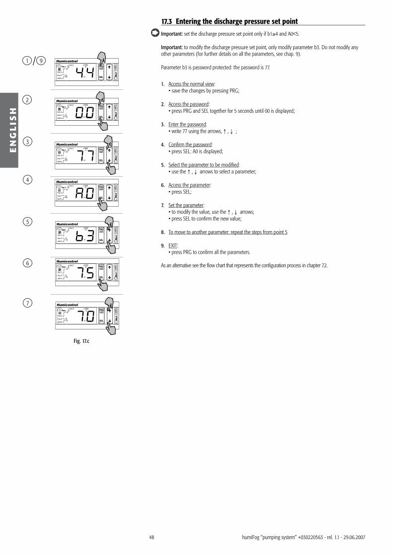
48
SEL
resetPRGx1000
alarm line 4
line 3
line 21
2
3
4
5
6
7
9
SEL
resetPRGx1000
alarm line 4
line 3
line 2
SEL
resetPRGx1000
alarm line 4
line 3
line 2
SEL
resetPRGx1000
alarm line 4
line 3
line 2
SEL
resetPRGx1000
alarm line 4
line 3
line 2
SEL
resetPRGx1000
alarm line 4
line 3
line 2
SEL
resetPRGx1000
alarm line 4
line 3
line 2
EN
GL
ISH
humiFog “pumping system” +0�022056� - rel. 1.1 - 29.06.2007
17.3 Entering the discharge pressure set point
Important: set the discharge pressure set point only if b1≥4 and A0<5.
Important: to modify the discharge pressure set point, only modify parameter b�. Do not modify any other parameters (for further details on all the parameters, see chap. 9).
Parameter b� is password protected: the password is 77.
1. Access the normal view: • save the changes by pressing PRG;
2. Access the password: • press PRG and SEL together for 5 seconds until 00 is displayed;
3. Enter the password: • write 77 using the arrows, ↑ , ↓ ;
4. Confirm the password: • press SEL: A0 is displayed;
5. Select the parameter to be modified: • use the ↑ , ↓ arrows to select a parameter;
6. Access the parameter: • press SEL;
7. Set the parameter: • to modify the value, use the ↑ , ↓ arrows; • press SEL to confirm the new value;
8. To move to another parameter: repeat the steps from point 5
9. EXIT: • press PRG to confirm all the parameters.
As an alternative see the flow chart that represents the configuration process in chapter 7.2.
Fig. 17.c

49
SEL
resetPRGx1000
alarm line 4
line 3
line 2
SEL
resetPRGx1000
alarm line 4
line 3
line 2
SEL
resetPRGx1000
alarm line 4
line 3
line 2
SEL
resetPRGx1000
alarm line 4
line 3
line 2
SEL
resetPRGx1000
alarm line 4
line 3
line 2
1
2
3
4
5
EN
GL
ISH
humiFog “pumping system” +0�022056� - rel. 1.1 - 29.06.2007
18. READING THE MEASUREMENTSDuring operation, the values measured by humiFog can be read. The measurements are shown below:
For “HD” versions with inverter
meas. description range UOM notesd1 room probe reading/ control signal from the external controller 0.0 to 100 % rH / % accessible if A0= 1, 2, � or 4d2 limit probe reading 0.0 to 100 % rH accessible if A0= 2 or 4d� current rack flow-rate (“HD” versions not available at constant
pressure)0.0 to 50 10 x kg/h depending on the unit of measure selected0.0 to 110 10 x lbs/h
d4 maintenance hour counter 0.0 to 19•9 (19900) hoursd5 supply water conductivity 0.0 to 19•9 (19900) µS/cmd6 pump discharge pressure 0.0 to 100 Bar depending on the unit of measure selected
0.0 to 1•5 (1500) PSId7 pump water outlet temperature 0.0 to 80 °C depending on the unit of measure selected
0.0 to 160 °Fd8 1st maintenance flag 0 to 1 --- 0= the hour counter d4 has not been reset
1= the hour counter d4 has been reset after the first maintenance signal (50 hours)
d9 rated flow rack 0.0 to 40 10 x kg/h depending on the unit of measure selected0.0 to 110 10 x lbs/h
Tab. 18.a
For “SL” versions with inverter
meas. description range UOM notesd1 Room probe reading/ external control signal 0.0 to 100 % rH Accessible if A0= 1, 2, �, or 4d2 Limit probe reading 0.0 to 100 % rH Accessible if A0= �,or 4d� % of production according to the capacity of the pump 0 to 100 %d4 Maintenance hour counter 0.0 to 19•9(19900) hours See the maintenance manuald5 Supply water conductivity 0.0 to 19•9(19900) µS/cmd6 Water bypass temperature 0.0 to 80 ºC Depending on the unit of measure selected
0.0 to 160 ºFd7 1st maintenance flag 0 to 1 --- 0: hour counter d4 has not been reset
1: hour counter d4 has been reset after the first maintenance signal (50 hours)
Tab. 18.b
1. Access the dx parameters: • press PRG for 5 seconds until displaying P0;
2. Move to the dx readings: • use the ↑ or ↓ arrows to select the desired parameter;
�. Access the readings: • to read the measurements, press and release SEL; • to return to the list of main parameters, press and release SEL;
4. Repeat: • use the ↑ or ↓ arrows to select another parameter and access it by pressing SEL as described in
point �;
5. Exit: • to exit press and release PRG.
Fig. 18.a

50
SEL
resetPRGx1000
alarm line 4
line 3
line 21
2
3
4
5
6
7
9
SEL
resetPRGx1000
alarm line 4
line 3
line 2
SEL
resetPRGx1000
alarm line 4
line 3
line 2
SEL
resetPRGx1000
alarm line 4
line 3
line 2
SEL
resetPRGx1000
alarm line 4
line 3
line 2
SEL
resetPRGx1000
alarm line 4
line 3
line 2
SEL
resetPRGx1000
alarm line 4
line 3
line 2
EN
GL
ISH
humiFog “pumping system” +0�022056� - rel. 1.1 - 29.06.2007
19. CONFIGURING THE CONTROLLERThe controller is programmed using the controller interface (as described in this chapter), the optional remote control, or the optional humivisor.
Please note that the parameters, the descriptions, the ranges and default values may change depending on the software version.
See chap. 15 to display the controller interface.
In case of doubts during the configuration of the controller, reset the default settings and restart the system.
19.1 Setting the parameters (level 3)The parameters are password protected: the password is 77.
1. Access the normal view: • save the changes by pressing PRG;
2. Access the password: • press PRG and SEL together for 5 seconds until 00 is displayed;
3. Enter the password: • write 77 using the arrows, ↑ , ↓;
4. Confirm the password: • press SEL: A0 is displayed;
5. Select the parameter to be modified: • use the ↑ , ↓ arrows to select a parameter;
6. Access the parameter: • press SEL;
7. Set the parameter: • to modify the value, use the ↑ , ↓ arrows; • press SEL to confirm the new value;
8. To move to another parameter: repeat the steps from point 5
9. EXIT: • press PRG to confirm all the parameters.
As an alternative see the flow chart that represents the configuration process in chapter 7.2.
19.2 Recalling the default parametersThis procedure can only be performed on power-up, as follows:1. within 5 seconds of power-up, press the PRG button until (around 5 seconds) the display shows
“-=-” with the top dash flashing;2. within � seconds, release the PRG button to confirm the operation for recalling and the permanently
saving the default parameters. When confirmed, the display shows “-=-” for 2 seconds.If the PRG button is not released in time, the normal initial waiting phase is completed (indicated by “-=-”), without modifying the parameters.
Fig. 19.a
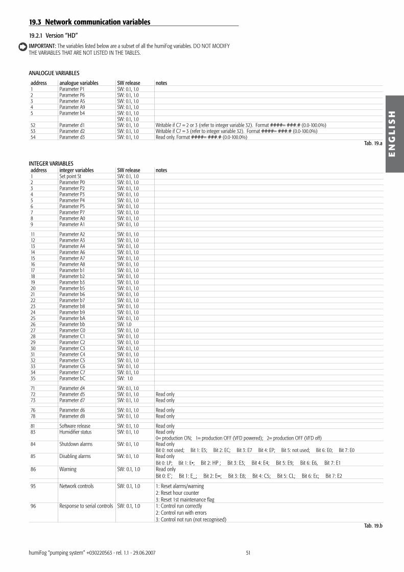
51
EN
GL
ISH
humiFog “pumping system” +0�022056� - rel. 1.1 - 29.06.2007
19.3 Network communication variables
19.2.1 Version “HD”
IMPORTANT: The variables listed below are a subset of all the humiFog variables. DO NOT MODIFY THE VARIABLES THAT ARE NOT LISTED IN THE TABLES.
ANALOGUE VARIABLES
address analogue variables SW release notes1 Parameter P1 SW: 0.1, 1.02 Parameter P6 SW: 0.1, 1.0� Parameter A5 SW: 0.1, 1.04 Parameter A9 SW: 0.1, 1.05 Parameter b4 SW: 0.1, 1.0
SW: 0.1, 1.052 Parameter d1 SW: 0.1, 1.0 Writable if C7 = 2 or � (refer to integer variable �2). Format ####= ###.# (0.0-100.0%)5� Parameter d2 SW: 0.1, 1.0 Writable if C7 = � (refer to integer variable �2). Format ####= ###.# (0.0-100.0%)54 Parameter d� SW: 0.1, 1.0 Read only. Format ####= ###.# (0.0-100.0%)
Tab. 19.a
INTEGER VARIABLESaddress integer variables SW release notes1 Set point St SW: 0.1, 1.02 Parameter P0 SW: 0.1, 1.0� Parameter P2 SW: 0.1, 1.04 Parameter P� SW: 0.1, 1.05 Parameter P4 SW: 0.1, 1.06 Parameter P5 SW: 0.1, 1.07 Parameter P7 SW: 0.1, 1.08 Parameter A0 SW: 0.1, 1.09 Parameter A1 SW: 0.1, 1.0
11 Parameter A2 SW: 0.1, 1.012 Parameter A� SW: 0.1, 1.01� Parameter A4 SW: 0.1, 1.014 Parameter A6 SW: 0.1, 1.015 Parameter A7 SW: 0.1, 1.016 Parameter A8 SW: 0.1, 1.017 Parameter b1 SW: 0.1, 1.018 Parameter b2 SW: 0.1, 1.019 Parameter b� SW: 0.1, 1.020 Parameter b5 SW: 0.1, 1.021 Parameter b6 SW: 0.1, 1.022 Parameter b7 SW: 0.1, 1.02� Parameter b8 SW: 0.1, 1.024 Parameter b9 SW: 0.1, 1.025 Parameter bA SW: 0.1, 1.026 Parameter bb SW: 1.027 Parameter C0 SW: 0.1, 1.028 Parameter C1 SW: 0.1, 1.029 Parameter C2 SW: 0.1, 1.0�0 Parameter C� SW: 0.1, 1.0�1 Parameter C4 SW: 0.1, 1.0�2 Parameter C5 SW: 0.1, 1.0�� Parameter C6 SW: 0.1, 1.0�4 Parameter C7 SW: 0.1, 1.0�5 Parameter bC SW: 1.0
71 Parameter d4 SW: 0.1, 1.072 Parameter d5 SW: 0.1, 1.0 Read only7� Parameter d7 SW: 0.1, 1.0 Read only
76 Parameter d6 SW: 0.1, 1.0 Read only78 Parameter d8 SW: 0.1, 1.0 Read only
81 Software release SW: 0.1, 1.0 Read only8� Humidifier status SW: 0.1, 1.0 Read only
0= production ON; 1= production OFF (VFD powered); 2= production OFF (VFD off)84 Shutdown alarms SW: 0.1, 1.0 Read only
Bit 0: not used; Bit 1: E5; Bit 2: EC; Bit �: E7 Bit 4: EP; Bit 5: not used; Bit 6: E0; Bit 7: E085 Disabling alarms SW: 0.1, 1.0 Read only
Bit 0: LP; Bit 1: E•; Bit 2: HP ; Bit �: E�; Bit 4: E4; Bit 5: E9; Bit 6: E6, Bit 7: E186 Warning SW: 0.1, 1.0 Read only
Bit 0: E¯; Bit 1: E_; Bit 2: E=; Bit �: E8; Bit 4: C5; Bit 5: CL; Bit 6: Ec; Bit 7: E2
95 Network controls SW: 0.1, 1.0 1: Reset alarms/warning2: Reset hour counter�: Reset 1st maintenance flag
96 Response to serial controls SW: 0.1, 1.0 1: Control run correctly2: Control run with errors�: Control not run (not recognised)
Tab. 19.b

52
EN
GL
ISH
humiFog “pumping system” +0�022056� - rel. 1.1 - 29.06.2007
BINARY VARIABLES
address binary variables SW release notes9 Humidifier disabled from remote on/off or from terminals
7I-8I or setting D15=1 (see D15 below)SW: 0.1, 1.0 Read only
10 Alarm EP SW: 0.1, 1.0 Read only11 Alarm HP SW: 0.1, 1.0 Read only12 Alarm LP SW: 0.1, 1.0 Read only
15 Remote on/off via network:D15=1 => humiFog disabledD15=0 => humiFog enabled
SW: 0.1, 1.0
17 Humidifier ready awaiting request for production SW: 0.1, 1.0 Read only
19 Request for production detected SW: 0.1, 1.0 Read only
24 Reset hardware control SW: 0.1, 1.0 To be sent in the following cases:• to set the new serial address AFTER this has been changed for variable C�• to start humiFog again as if it were switched off and on again
�4 Alarm E5 SW: 0.1, 1.0 Read only�5 Alarm EC SW: 0.1, 1.0 Read only�6 Alarm E8 SW: 0.1, 1.0 Read only�7 Alarm EP SW: 0.1, 1.0 Read only�9 Alarm E0 SW: 0.1, 1.0 Read only40 Alarm E0 SW: 0.1, 1.0 Read only41 Alarm LP SW: 0.1, 1.0 Read only42 Alarm El SW: 0.1, 1.0 Read only4� Alarm HP SW: 0.1, 1.0 Read only44 Alarm E� SW: 0.1, 1.0 Read only45 Alarm E4 SW: 0.1, 1.0 Read only46 Alarm E9 SW: 0.1, 1.0 Read only47 Alarm E6 SW: 0.1, 1.0 Read only48 Alarm E1 SW: 0.1, 1.0 Read only49 Warning E¯ SW: 0.1, 1.0 Read only50 Warning E_ SW: 0.1, 1.0 Read only51 Warning E= SW: 0.1, 1.0 Read only52 Warning E8 SW: 0.1, 1.0 Read only5� Warning C5 SW: 0.1, 1.0 Read only54 Warning CL SW: 0.1, 1.0 Read only55 Warning Ec SW: 0.1, 1.0 Read only56 Warning E2 SW: 0.1, 1.0 Read only
Tab. 19.c
19.2.2 Version “SL”
IMPORTANT: The variables listed below are a subset of all the humiFog variables. DO NOT MODIFY THE VARIABLES THAT ARE NOT LISTED IN THE TABLES.
ANALOGUE VARIABLES
address analogue variables SW release notes1 Parameter P1 SW: 0.12 Parameter P6 SW: 0.1� Parameter A5 SW: 0.14 Parameter A9 SW: 0.15 Parameter b8 SW: 0.16 Parameter bb SW: 0.17 Parameter bC SW: 0.18 Parameter bD SW: 0.1
SW: 0.152 Parameter d1 SW: 0.1 Writable if C7 = 2 or � (refer to integer variable �2). Format ???? = ???.? (0.0-100.0%)
5� Parameter d2 SW: 0.1 Writable if C7 = � (refer to integer variable �2). Format ???? = ???.? (0.0-100.0%)
54 Parameter d� SW: 0.1 Read only. Format ####= ###.# (0.0-100.0%)Tab. 19.d
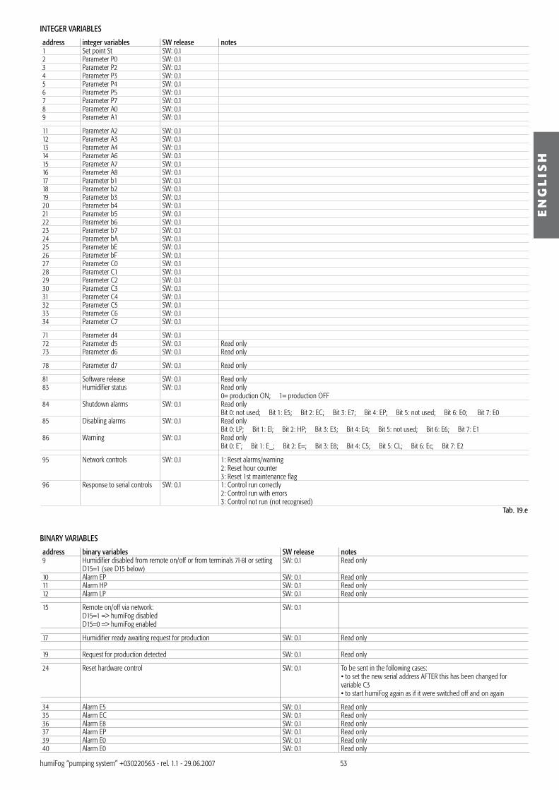
5�
EN
GL
ISH
humiFog “pumping system” +0�022056� - rel. 1.1 - 29.06.2007
INTEGER VARIABLES
address integer variables SW release notes1 Set point St SW: 0.12 Parameter P0 SW: 0.1� Parameter P2 SW: 0.14 Parameter P� SW: 0.15 Parameter P4 SW: 0.16 Parameter P5 SW: 0.17 Parameter P7 SW: 0.18 Parameter A0 SW: 0.19 Parameter A1 SW: 0.1
11 Parameter A2 SW: 0.112 Parameter A� SW: 0.11� Parameter A4 SW: 0.114 Parameter A6 SW: 0.115 Parameter A7 SW: 0.116 Parameter A8 SW: 0.117 Parameter b1 SW: 0.118 Parameter b2 SW: 0.119 Parameter b� SW: 0.120 Parameter b4 SW: 0.121 Parameter b5 SW: 0.122 Parameter b6 SW: 0.12� Parameter b7 SW: 0.124 Parameter bA SW: 0.125 Parameter bE SW: 0.126 Parameter bF SW: 0.127 Parameter C0 SW: 0.128 Parameter C1 SW: 0.129 Parameter C2 SW: 0.1�0 Parameter C� SW: 0.1�1 Parameter C4 SW: 0.1�2 Parameter C5 SW: 0.1�� Parameter C6 SW: 0.1�4 Parameter C7 SW: 0.1
71 Parameter d4 SW: 0.172 Parameter d5 SW: 0.1 Read only7� Parameter d6 SW: 0.1 Read only
78 Parameter d7 SW: 0.1 Read only
81 Software release SW: 0.1 Read only8� Humidifier status SW: 0.1 Read only
0= production ON; 1= production OFF84 Shutdown alarms SW: 0.1 Read only
Bit 0: not used; Bit 1: E5; Bit 2: EC; Bit �: E7; Bit 4: EP; Bit 5: not used; Bit 6: E0; Bit 7: E085 Disabling alarms SW: 0.1 Read only
Bit 0: LP; Bit 1: El; Bit 2: HP; Bit �: E�; Bit 4: E4; Bit 5: not used; Bit 6: E6; Bit 7: E186 Warning SW: 0.1 Read only
Bit 0: E¯; Bit 1: E_; Bit 2: E=; Bit �: E8; Bit 4: C5; Bit 5: CL; Bit 6: Ec; Bit 7: E2
95 Network controls SW: 0.1 1: Reset alarms/warning2: Reset hour counter�: Reset 1st maintenance flag
96 Response to serial controls SW: 0.1 1: Control run correctly2: Control run with errors�: Control not run (not recognised)
Tab. 19.e
BINARY VARIABLES
address binary variables SW release notes9 Humidifier disabled from remote on/off or from terminals 7I-8I or setting
D15=1 (see D15 below)SW: 0.1 Read only
10 Alarm EP SW: 0.1 Read only11 Alarm HP SW: 0.1 Read only12 Alarm LP SW: 0.1 Read only
15 Remote on/off via network:D15=1 => humiFog disabledD15=0 => humiFog enabled
SW: 0.1
17 Humidifier ready awaiting request for production SW: 0.1 Read only
19 Request for production detected SW: 0.1 Read only
24 Reset hardware control SW: 0.1 To be sent in the following cases:• to set the new serial address AFTER this has been changed for variable C�• to start humiFog again as if it were switched off and on again
�4 Alarm E5 SW: 0.1 Read only�5 Alarm EC SW: 0.1 Read only�6 Alarm E8 SW: 0.1 Read only�7 Alarm EP SW: 0.1 Read only�9 Alarm E0 SW: 0.1 Read only40 Alarm E0 SW: 0.1 Read only

54
EN
GL
ISH
humiFog “pumping system” +0�022056� - rel. 1.1 - 29.06.2007
address binary variables SW release notes41 Alarm LP SW: 0.1 Read only42 Alarm El SW: 0.1 Read only4� Alarm HP SW: 0.1 Read only44 Alarm E� SW: 0.1 Read only45 Alarm E4 SW: 0.1 Read only47 Alarm E6 SW: 0.1 Read only48 Alarm E1 SW: 0.1 Read only49 Warning E¯ SW: 0.1 Read only50 Warning E_ SW: 0.1 Read only51 Warning E= SW: 0.1 Read only52 Warning E8 SW: 0.1 Read only5� Warning C5 SW: 0.1 Read only54 Warning CL SW: 0.1 Read only55 Warning Ec SW: 0.1 Read only56 Warning E2 SW: 0.1 Read only
Tab. 19.f
19.4 Configuration parameters: checklistThe checklist for the configuration of the parameters must be completed at the end of the installation process to ensure the correct configuration of the main parameters. The parameters that are not listed in the checklist below may be specific, and for this reason CAREL recommends that all the parameters should be rechecked before installation.
In the checklist, the default parameters are indicated as reference values; the parameters do not need to be set as the default settings are already correct.
1. make sure that the external control signal is 0 (if present);2. make sure that the water supply is open;�. switch on humiFog with the main switch;4. switch on the controller; 5. immediately set the room probe set point to 0% rH (if the room probe is present), to prevent humiFog from operating during configuration.
For HD version with inverter
code description of the parameter notes default settingsA0 Control algorithm � (H1) = humidity probeA1 Unit of measure management 0=°C, kg/h, bar (metric system)A2 Type of electrical control signal from room probe/ external controller 0=0/1VA6 Type of limit probe control signal (if present) 0=0/1Vb1 VFD management option, alarm relay, operating mode (variable or
constant pressure)0
b2 Minimum operating pressure In pressure control mode: minimum pressure set point 25 barb� Maximum operating pressure In pressure control mode: maximum pressure set point 75 barb4 Rated rack flow-rate Not accessible in pressure control mode 0 kg/hb7 Number of independent branches controlled by solenoid valves Not accessible in pressure control mode �bB Filling time 5 minutesC0 Value normally displayed 1= room probe readingC1 Enable keypad and remote control: keypad 4= read and set all the parametersP0 Maximum production as a percentage compared to the rated rack flow-
rateNot accessible in pressure control mode 70%
P5 Outlet set point 100% rHSt Humidification set point 50% rH
Tab. 19.g
For SL version with inverter
code description of the parameter notes default settingsA0 Operating mode �= humidity probeA1 Unit of measure management 0=°C, kg/h, bar (metric system)A2 Type of probe 1 0=0/1VA6 Type of probe 2 0=0/1Vb1 Management option 0b2 Low discharge pressure alarm delay � minutesb� Waiting time for automatic washing when the pump stops Available only if automatic wash enabled (weight 4 in B1) 24 hoursb7 Number of independent branches controlled by solenoid valves �bB Filling time 5 minutesbe Washing time 5 minutesbf Time required to bring the circuit from 0 to 100% of production demand 60 sC0 Value normally displayed 1= room probe readingC1 Enable keypad and remote control: keypad 4= read and set all the parametersP0 Maximum production as a percentage compared to the rated rack flow-
rateNot accessible in pressure control mode 70%
P5 Outlet set point 100% rHSt Humidification set point 50% rH
Tab. 19.h
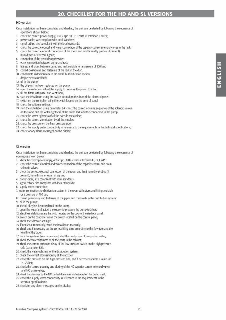
55
EN
GL
ISH
humiFog “pumping system” +0�022056� - rel. 1.1 - 29.06.2007
20. CHECKLIST FOR THE HD AND SL VERSIONSHD version
Once installation has been completed and checked, the unit can be started by following the sequence of operations shown below:
1. check the correct power supply, 2�0 V 1ph 50 Hz + earth at terminals L N+PE;2. power cable; size compliant with local standards;�. signal cables: size compliant with the local standards;4. check the correct electrical and water connection of the capacity control solenoid valves in the rack;5. check the correct electrical connection of the room and limit humidity probes (if present),
humidistats or external signals;6. connection of the treated supply water;7. water connection between pump and rack;8. fittings and pipes between pump and rack suitable for a pressure of 100 bar;9. correct positioning and fastening of the rack in the duct.10. condensate collection tank in the entire humidification section;11. droplet separator fitted;12. oil in the pump;1�. the oil plug has been replaced on the pump;14. open the water and adjust the supply to pressure the pump to 2 bar;15. fill the filters with water and vent them;16. start the installation using the switch located on the door of the electrical panel;17. switch on the controller using the switch located on the control panel;18. check the software settings;19. start the installation using parameter bA: check the correct opening sequence of the solenoid valves
on the racks and the water-tightness of the entire rack and the connection to the pump;20. check the water-tightness of all the parts in the cabinet;21. check the correct atomisation by all the nozzles;22. check the pressure on the high pressure side;2�. check the supply water conductivity in reference to the requirements in the technical specifications;24. check for any alarm messages on the display.
SL version
Once installation has been completed and checked, the unit can be started by following the sequence of operations shown below:1. check the correct power supply, 400 V �ph 50 Hz + earth at terminals L1, L2, L�+PE;2. check the correct electrical and water connection of the capacity control and drain solenoid valves;�. check the correct electrical connection of the room and limit humidity probes (if present), humidistats or external signals;4. power cable; size compliant with local standards;5. signal cables: size compliant with local standards;6. supply water connection;7. water connections to distribution system in the room with pipes and fittings suitable for a pressure of 100 bar;8. correct positioning and fastening of the pipes and manifolds in the distribution system;9. oil in the pump;10. the oil plug has been replaced on the pump;11. open the water and adjust the supply to pressure the pump to 2 bar;12. start the installation using the switch located on the door of the electrical panel;1�. switch on the controller using the switch located on the control panel;14. check the software settings;15. if not set automatically, wash the installation manually;16. check and if necessary set the correct filling time according to the flow-rate and the length of the pipes;17. once the washing time has expired, start the production of pressurised water;18. check the water-tightness of all the parts in the cabinet;19. check the correct activation delay of the low pressure switch on the high pressure side (parameter B2);20. check the water-tightness of the distribution system;21. check the correct atomisation by all the nozzles;22. check the pressure on the high pressure side, and if necessary restore a value of 70-75 bar;2�. check the correct opening and closing of the NC capacity control solenoid valves and NO drain valves;24. check the drainage by the NO central drain solenoid valve when the pump is off;25. check the supply water conductivity in reference to the requirements in the technical specifications;26. check for any alarm messages on the display.

56
SEL
resetPRGx1000
alarm line 4
line 3
line 21 6
2
3
4
5
SEL
resetPRGx1000
alarm line 4
line 3
line 2
SEL
resetPRGx1000
alarm line 4
line 3
line 2
SEL
resetPRGx1000
alarm line 4
line 3
line 2
SEL
resetPRGx1000
alarm line 4
line 3
line 2
EN
GL
ISH
humiFog “pumping system” +0�022056� - rel. 1.1 - 29.06.2007
21. PREVENTIVE MAINTENANCE
Check After the first 50 hours Monthly Every 2000 hours(1) Every 3000/4000 hours(1) seePump:initial oil change X 5.2.1water filters X 1.2check oil level X 1.�change oil X 5.2.1replace gasket Xreplace valve XRack and room distribution system:nozzles blocked X 1.4water leaks X 1.4solenoid valve X 1.4accessoriescheck drain X 1.5.1check droplet separator X 1.5.2
Tab. 21.a(1): “HD” version with SW rel. 0.1 and 1.0 and “SL” version with SW rel. 0.1
Installations in AHU or ducts must, in addition, comply with the national maintenance standards (ASHRAE 12-2000, VDI 6022, etc.)
Please note that:• the personnel in charge of maintenance are responsible for any malfunctions due to a lack of
preventive maintenance. The controller will show the maintenance warning code “C5” after the first 50 hours and, subsequently, the routine maintenance warning code “CL” every 2000 hours as a reminder for the following operations;
• the personnel in charge of maintenance must reset the hour counter after having performed the preventive maintenance operations listed in the columns “AFTER 50 HOURS”, “EVERY 2000 HOURS”, “EVERY 4000 HOURS”. If the hour counter is not reset, the maintenance warnings will no longer be signalled;
• the maintenance signals do not stop the operation of humiFog.
21.1 Maintenance parametersThe maintenance parameters are:• d4: hour counter (alarm “CL” every 2000 hours);• d8: 1st maintenance flag (alarm “C5” after the first 50 hours).
21.1.1 Hour counter “d4”The hour counter parameter “d4” is associated with a timer that counts the operating hours starting from the last maintenance operation, between a minimum of 0 and a maximum of 19,900 hours.Once the initial period of 50 hours has expired, the maintenance warning “C5” is activated. If the maintenance personnel has reset hour counter d4, the maintenance warning “CL” will be issued every 2000 hours.The value of d4 corresponds to reality only if the maintenance personnel complete the maintenance operations.
To reset hour counter d4, proceed as follows:
1 Access the normal view: N.B.: press and release PRG to save any changes to the parameters;
2 Access the Px parameters: • press PRG for 5 seconds until displaying P0;
3 Move to d4: • scroll the parameters using the ↑, ↓ arrows until displaying d4;
4 Access d4: • press SEL; • the value of d4 is displayed (e.g. 1’5, equal to 2000 hours);
5 Reset d4: • press ↑ and ↓ at the same time until displaying 00 (around 5 seconds);
6 Exit: • press and release PRG.
Fig. 21.a

57
LP
1 µ 5 µ
PIN
PUSC
1
EN
GL
ISH
humiFog “pumping system” +0�022056� - rel. 1.1 - 29.06.2007
21.1.2 First maintenance flag d8The 1st maintenance flag associated with parameter “d8” is a read-only parameter. Before humiFog is started, the flag is equal to 0.If the hour counter d4 is reset after the initial maintenance warning “C5” is issued, the controller sets d8 to 1, assuming that the oil has been changed.Please note that the value of “d8” only corresponds to reality if the relevant personnel complete the maintenance operations.
21.2 Preventive maintenance of the water filter1. access the water circuit;2. open the external water supply valve;�. check the pressure drop across the water filters.
∆P = PIN - PUSC ≤ 0.5 bar? YES ↑ complete the remaining maintenance operations NO ↑ replace the cartridges: see the spare parts manual
Tab. 21.b
21.3 Preventive maintenance of the pump: checking the oil level1. access the water circuit; 2. check that the oil level is correct (see the drawing below).
oil level correct? YES ↑ complete the remaining maintenance operationsNO ↑ � identify the oil leaks (see the pump manual) 4 add or remove oil until reaching the correct level (refer to 5.2.1)
Tab. 21.c
The drawing shows the front of the transparent Plexiglas oil level indicator.
Fig. 21.c
Fig. 21.b

58
EN
GL
ISH
humiFog “pumping system” +0�022056� - rel. 1.1 - 29.06.2007
?
22. TROUBLESHOOTINGThe identification and solution of the problem may vary depending on the version of the software: chapter 9 “Controller parameters” explains how to display the version of the software.
Troubleshooting for the HD version
PROBLEM POSSIBLE CAUSES CHECKING PROCEDURE SOLUTIONno power supply (controller doesn’t start).
Incorrect power supply or fuses on the transformer primary blown.
Use a tester and check the power supply at the terminals on the terminal block. Refer to the wiring diagram
2�0 Vac � ph power supply. Replace any blown fuses. See the wiring diagram
Fuse on transformer low voltage side blown
Use a tester to check the electrical continuity at the ends of the fuse.
Replace the fuse.
Transformer defective. Use a tester to check for 24 volts at the secondary Replace the transformerController or board defective Use a tester to check the correct power supply to the
board and the controller.Replace controller and board
Is the main switch on? Check the position of the main switch. Turn the knob on the main switch located on the door of the electrical panel
no atomisation at all or insufficient atomisation
Is the remote ON-OFF contact closed? Check the connection (or presence of jumper) at terminals 7I and 8I.
Connect terminals 7I and 8I to the remote contact, if not jumper the two terminals.
Check control algorithm. Refer to parameter “A0” Set parameter A0; see the section on setting the parameters in chap. 19
No supply water Check for LP alarm on the controller display Check the water supply upstream and downstream of the filters and restore the water supply
Low supply water pressure Calibrate the pressure of the supply water to 2 bar1 µ and from 5 µ water filters blocked Check the pressure measured by the pressure gau-
ges upstream and downstream of the water filters Replace the 1 and 5 µ water filters
Water leaks from the rack or the connec-tion circuit between humiFog and rack.
Alarm E7 Repair the causes of any water leaks.
Low discharge pressure replace the worn gaskets and valves on the pump: (see the spare parts manual or pump manual)
Activation of VFD protection Alarm EP Check VFD configurationAlarm EP, VFD on and high motor temperature Electric motor overload
Nozzles blocked Nozzles do not atomise or atomise incorrectly Clean the nozzlesAlarms Ec, EC,E8 Check the quality of the supply water
Capacity control solenoid valves blocked Incorrect electrical connection Connect the power supply of the solenoid valve correctly (see wiring diagram)
Solenoid valve position not vertical Reposition the solenoid valve correctlyCheck configuration of control parameter b7 Enter the correct number of capacity control
branches for parameter “b7”some nozzles do not atomise correctly
Some capacity control solenoid valves not open
Position of solenoid valve not correctly vertical Reposition the solenoid valve
Too many nozzles for the flow-rate of the pump
With maximum production demand some solenoid valves do no open
Choose a larger pump or decrease the number of nozzles
droplets atomised by the nozzles too large
Low pressure. Check the pressure displayed by the pressure gauge, this must be between the 60-75 bar.
Adjust the pressure using the cap on the high pressure regulator
Too many nozzles for the flow-rate of the pump
Check the flow-rate of the pump and the distribution system installed
Decrease the number of the nozzles; choose a pump with a higher flow-rate
high discharge pressure alarm Some lines downstream of the pump are choked/blocked
Check the pressure on the pressure gauge located on the pump
Restore the discharge circuit, high pressure side, freeing the circuit from any obstructions.
continuous discharge of water by the thermal valve
Water temperature in the bypass above 60ºC
Check that there are no blockages downstream of the pump
Restore the discharge circuit, high pressure side, freeing the circuit from any obstructions.
Check if alarm E° is displayedexcessive discharge of water from the pressure relief valve.
Supply water pressure adjustment too high.
Check the pressure measured by the pressure gauges on the low pressure side: with the unit on the pressure should settle at 2 bar.
Adjust the supply water pressure to 2 bar using the pressure regulator.
Pressure relief valve pressure adjustment too low
Check the pressure measured by the pressure gauges on the low pressure side: at a pressure of 2 bar the pressure relief valve must not discharge.
Turn the knob on the pressure relief valve clockwise to increase the activation pressure to a value above 2 bar.
Pressure relief valve defective The water loss still continues when adjusting the pressure.
Replace the pressure relief valve.
the humiFog starts at maximum production even with minimum demand.
Humidity probe powered with incorrect voltage
Check the setting of parameter A2 Configure parameter A2 according to the power supply of the humidity probe connected.
the humiFog starts at minimum production even with maximum demand.
Humidity probe powered with incorrect voltage
Check the setting of parameter A2 Configure parameter A2 according to the power supply of the humidity probe connected.
Tab. 22.a
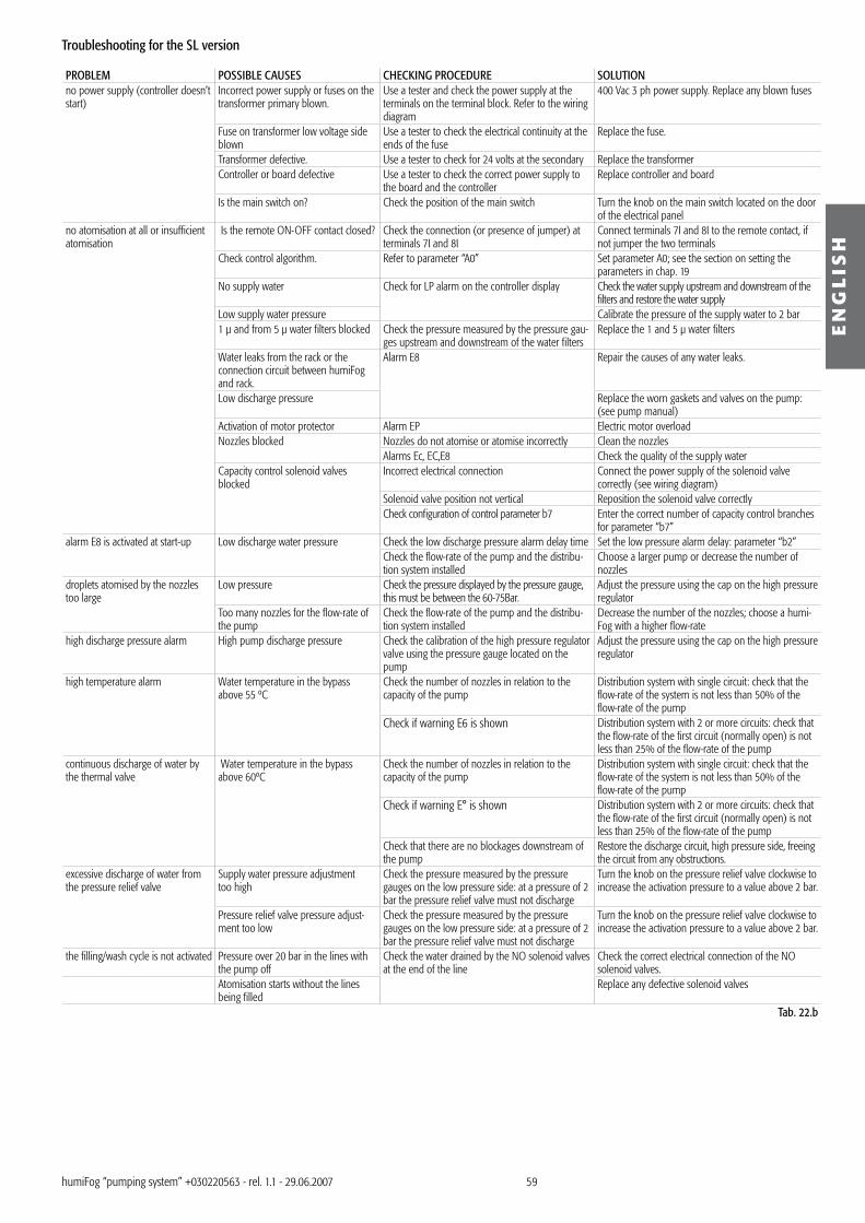
59
EN
GL
ISH
humiFog “pumping system” +0�022056� - rel. 1.1 - 29.06.2007
Troubleshooting for the SL version
PROBLEM POSSIBLE CAUSES CHECKING PROCEDURE SOLUTIONno power supply (controller doesn’t start)
Incorrect power supply or fuses on the transformer primary blown.
Use a tester and check the power supply at the terminals on the terminal block. Refer to the wiring diagram
400 Vac � ph power supply. Replace any blown fuses
Fuse on transformer low voltage side blown
Use a tester to check the electrical continuity at the ends of the fuse
Replace the fuse.
Transformer defective. Use a tester to check for 24 volts at the secondary Replace the transformerController or board defective Use a tester to check the correct power supply to
the board and the controllerReplace controller and board
Is the main switch on? Check the position of the main switch Turn the knob on the main switch located on the door of the electrical panel
no atomisation at all or insufficient atomisation
Is the remote ON-OFF contact closed? Check the connection (or presence of jumper) at terminals 7I and 8I
Connect terminals 7I and 8I to the remote contact, if not jumper the two terminals
Check control algorithm. Refer to parameter “A0” Set parameter A0; see the section on setting the parameters in chap. 19
No supply water Check for LP alarm on the controller display Check the water supply upstream and downstream of the filters and restore the water supply
Low supply water pressure Calibrate the pressure of the supply water to 2 bar1 µ and from 5 µ water filters blocked Check the pressure measured by the pressure gau-
ges upstream and downstream of the water filtersReplace the 1 and 5 µ water filters
Water leaks from the rack or the connection circuit between humiFog and rack.
Alarm E8 Repair the causes of any water leaks.
Low discharge pressure Replace the worn gaskets and valves on the pump: (see pump manual)
Activation of motor protector Alarm EP Electric motor overloadNozzles blocked Nozzles do not atomise or atomise incorrectly Clean the nozzles
Alarms Ec, EC,E8 Check the quality of the supply waterCapacity control solenoid valves blocked
Incorrect electrical connection Connect the power supply of the solenoid valve correctly (see wiring diagram)
Solenoid valve position not vertical Reposition the solenoid valve correctlyCheck configuration of control parameter b7 Enter the correct number of capacity control branches
for parameter “b7”alarm E8 is activated at start-up Low discharge water pressure Check the low discharge pressure alarm delay time Set the low pressure alarm delay: parameter “b2”
Check the flow-rate of the pump and the distribu-tion system installed
Choose a larger pump or decrease the number of nozzles
droplets atomised by the nozzles too large
Low pressure Check the pressure displayed by the pressure gauge, this must be between the 60-75Bar.
Adjust the pressure using the cap on the high pressure regulator
Too many nozzles for the flow-rate of the pump
Check the flow-rate of the pump and the distribu-tion system installed
Decrease the number of the nozzles; choose a humi-Fog with a higher flow-rate
high discharge pressure alarm High pump discharge pressure Check the calibration of the high pressure regulator valve using the pressure gauge located on the pump
Adjust the pressure using the cap on the high pressure regulator
high temperature alarm Water temperature in the bypass above 55 ºC
Check the number of nozzles in relation to the capacity of the pump
Distribution system with single circuit: check that the flow-rate of the system is not less than 50% of the flow-rate of the pump
Check if warning E6 is shown Distribution system with 2 or more circuits: check that the flow-rate of the first circuit (normally open) is not less than 25% of the flow-rate of the pump
continuous discharge of water by the thermal valve
Water temperature in the bypass above 60ºC
Check the number of nozzles in relation to the capacity of the pump
Distribution system with single circuit: check that the flow-rate of the system is not less than 50% of the flow-rate of the pump
Check if warning E° is shown Distribution system with 2 or more circuits: check that the flow-rate of the first circuit (normally open) is not less than 25% of the flow-rate of the pump
Check that there are no blockages downstream of the pump
Restore the discharge circuit, high pressure side, freeing the circuit from any obstructions.
excessive discharge of water from the pressure relief valve
Supply water pressure adjustment too high
Check the pressure measured by the pressure gauges on the low pressure side: at a pressure of 2 bar the pressure relief valve must not discharge
Turn the knob on the pressure relief valve clockwise to increase the activation pressure to a value above 2 bar.
Pressure relief valve pressure adjust-ment too low
Check the pressure measured by the pressure gauges on the low pressure side: at a pressure of 2 bar the pressure relief valve must not discharge
Turn the knob on the pressure relief valve clockwise to increase the activation pressure to a value above 2 bar.
the filling/wash cycle is not activated Pressure over 20 bar in the lines with the pump off
Check the water drained by the NO solenoid valves at the end of the line
Check the correct electrical connection of the NO solenoid valves.
Atomisation starts without the lines being filled
Replace any defective solenoid valves
Tab. 22.b
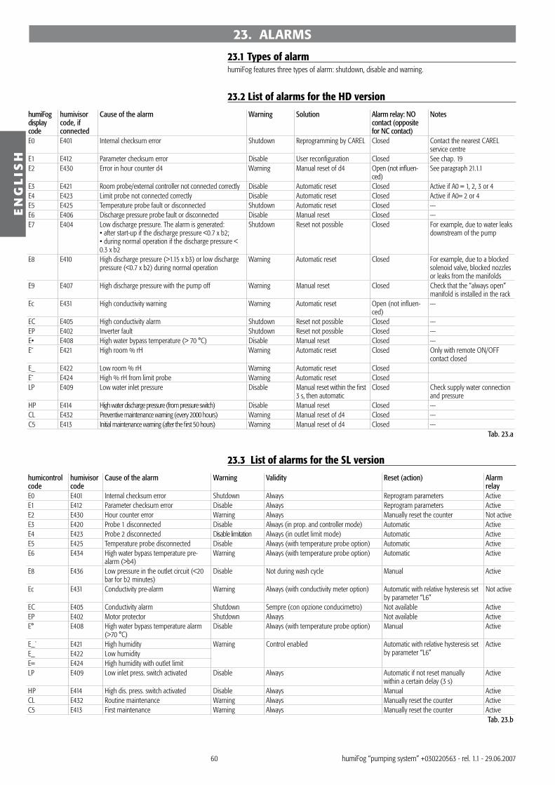
60
EN
GL
ISH
humiFog “pumping system” +0�022056� - rel. 1.1 - 29.06.2007
23. ALARMS
23.1 Types of alarmhumiFog features three types of alarm: shutdown, disable and warning.
23.2 List of alarms for the HD version
humiFog display code
humivisor code, if connected
Cause of the alarm Warning Solution Alarm relay: NO contact (opposite for NC contact)
Notes
E0 E401 Internal checksum error Shutdown Reprogramming by CAREL Closed Contact the nearest CAREL service centre
E1 E412 Parameter checksum error Disable User reconfiguration Closed See chap. 19E2 E4�0 Error in hour counter d4 Warning Manual reset of d4 Open (not influen-
ced)See paragraph 21.1.1
E� E421 Room probe/external controller not connected correctly Disable Automatic reset Closed Active if A0 = 1, 2, � or 4E4 E42� Limit probe not connected correctly Disable Automatic reset Closed Active if A0= 2 or 4E5 E425 Temperature probe fault or disconnected Shutdown Automatic reset Closed ---E6 E406 Discharge pressure probe fault or disconnected Disable Manual reset Closed ---E7 E404 Low discharge pressure. The alarm is generated:
• after start-up if the discharge pressure <0.7 x b2;• during normal operation if the discharge pressure < 0.� x b2
Shutdown Reset not possible Closed For example, due to water leaks downstream of the pump
E8 E410 High discharge pressure (>1.15 x b�) or low discharge pressure (<0.7 x b2) during normal operation
Warning Automatic reset Closed For example, due to a blocked solenoid valve, blocked nozzles or leaks from the manifolds
E9 E407 High discharge pressure with the pump off Warning Manual reset Closed Check that the “always open” manifold is installed in the rack
Ec E4�1 High conductivity warning Warning Automatic reset Open (not influen-ced)
---
EC E405 High conductivity alarm Shutdown Reset not possible Closed ---EP E402 Inverter fault Shutdown Reset not possible Closed ---E• E408 High water bypass temperature (> 70 °C) Disable Manual reset Closed ---E¯ E421 High room % rH Warning Automatic reset Closed Only with remote ON/OFF
contact closedE_ E422 Low room % rH Warning Automatic reset ClosedE¯ E424 High % rH from limit probe Warning Automatic reset ClosedLP E409 Low water inlet pressure Disable Manual reset within the first
� s, then automaticClosed Check supply water connection
and pressureHP E414 High water discharge pressure (from pressure switch) Disable Manual reset Closed ---CL E4�2 Preventive maintenance warning (every 2000 hours) Warning Manual reset of d4 Closed ---C5 E41� Initial maintenance warning (after the first 50 hours) Warning Manual reset of d4 Closed ---
Tab. 23.a
23.3 List of alarms for the SL version
humicontrol code
humivisor code
Cause of the alarm Warning Validity Reset (action) Alarm relay
E0 E401 Internal checksum error Shutdown Always Reprogram parameters ActiveE1 E412 Parameter checksum error Disable Always Reprogram parameters ActiveE2 E4�0 Hour counter error Warning Always Manually reset the counter Not activeE� E420 Probe 1 disconnected Disable Always (in prop. and controller mode) Automatic ActiveE4 E42� Probe 2 disconnected Disable limitation Always (in outlet limit mode) Automatic ActiveE5 E425 Temperature probe disconnected Disable Always (with temperature probe option) Automatic ActiveE6 E4�4 High water bypass temperature pre-
alarm (>b4)Warning Always (with temperature probe option) Automatic Active
E8 E4�6 Low pressure in the outlet circuit (<20 bar for b2 minutes)
Disable Not during wash cycle Manual Active
Ec E4�1 Conductivity pre-alarm Warning Always (with conductivity meter option) Automatic with relative hysteresis set by parameter “L6”
Not active
EC E405 Conductivity alarm Shutdown Sempre (con opzione conducimetro) Not available ActiveEP E402 Motor protector Shutdown Always Not available ActiveE° E408 High water bypass temperature alarm
(>70 °C)Disable Always (with temperature probe option) Manual Active
E_` E421 High humidity Warning Control enabled Automatic with relative hysteresis set by parameter “L6”
ActiveE_ E422 Low humidityE= E424 High humidity with outlet limitLP E409 Low inlet press. switch activated Disable Always Automatic if not reset manually
within a certain delay (� s)Active
HP E414 High dis. press. switch activated Disable Always Manual ActiveCL E4�2 Routine maintenance Warning Always Manually reset the counter ActiveC5 E41� First maintenance Warning Always Manually reset the counter Active
Tab. 23.b

Note: __________________________________________________________________________________
______________________________________________________________________________________
______________________________________________________________________________________
______________________________________________________________________________________
______________________________________________________________________________________
______________________________________________________________________________________
______________________________________________________________________________________
______________________________________________________________________________________
______________________________________________________________________________________
______________________________________________________________________________________
______________________________________________________________________________________
______________________________________________________________________________________
______________________________________________________________________________________
______________________________________________________________________________________
______________________________________________________________________________________
______________________________________________________________________________________
______________________________________________________________________________________
______________________________________________________________________________________
______________________________________________________________________________________
______________________________________________________________________________________
______________________________________________________________________________________
______________________________________________________________________________________
______________________________________________________________________________________
______________________________________________________________________________________
______________________________________________________________________________________
______________________________________________________________________________________
______________________________________________________________________________________
______________________________________________________________________________________
______________________________________________________________________________________
______________________________________________________________________________________
______________________________________________________________________________________
______________________________________________________________________________________
______________________________________________________________________________________


CAREL S.p.A.Via dell’Industria, 11 - 35020 Brugine - Padova (Italy)Tel. (+39) 049.9716611 - Fax (+39) 049.9716600e-mail: [email protected] - www.carel.com
Agenzia / Agency:
+0�0
2205
6� r
el. 1
.1 - 2
9.06
.200
7CA
REL
rese
rves
the
right
to m
odify
the
feat
ures
of i
ts pr
oduc
ts wi
thou
t prio
r not
ice