pumped thermal exergy storage past, present and...
TRANSCRIPT

Pumped Thermal Exergy Storage Past, Present and Future
Alexander White
Josh McTigue, Pau Farres-Antunez, Haobai Xue
Caroline Willich, Christos Markides (Imperial), Chris Dent (Durham)
Department of Engineering
UK Energy Storage Conference Birmingham. 1st December 2016

What is Pumped Thermal Exergy Storage?
• The literature uses several names… • PHES: Pumped Heat Electricity Storage • TEES: Thermo-Electrical Energy Storage
Work Work + ? Thermal exergy Thermal exergy Heat pump Heat engine Storage
CHEST: Compressed Heat Energy Storage SEPT: Stockage d’Electricité par Pompage Thermique
UKES 2016 Birmingham

UKES 2016 Birmingham
Hot Storage
Cold Storage
Combined
CHP
Th
pW
Q0
Qc
CHP
pW
Qh
Qc
Tc
Th
T
CHP
c
pW
Qh
Q0
T0
Possible embodiments of PTES

UKES 2016 Birmingham
Possible embodiments of PTES (red = Isentropic’s PHES)
• Storage type:
- hot / cold / combined
- sensible heat / latent heat
- packed bed / liquid tank / other (e.g., concrete)
• Thermodynamic cycle:
- Rankine / Joule-Brayton / other (e.g., transcritical CO2)
• Compression & expansion:
- turbomachinery / reciprocating / other
• Heat exchange:
- direct (packed bed) / intermediate HX
UKES 2016 Birmingham
A (very) brief history of PTES
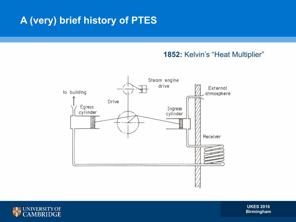
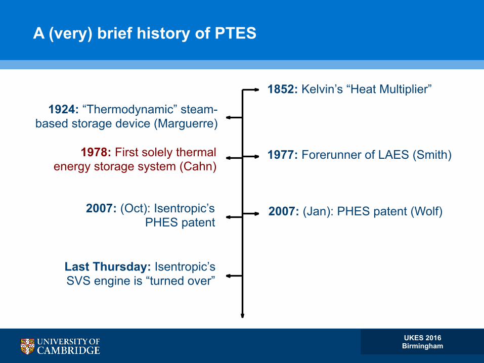
1852: Kelvin’s “Heat Multiplier”
2007: (Oct): Isentropic’s PHES patent
UKES 2016 Birmingham
A (very) brief history of PTES
1852: Kelvin’s “Heat Multiplier”
1924: “Thermodynamic” steam- based storage device (Marguerre)
1977: Forerunner of LAES (Smith) 1978: First solely thermal energy storage system (Cahn)
2007: (Jan): PHES patent (Wolf) 2007: (Oct): Isentropic’s PHES patent
Last Thursday: Isentropic’s SVS engine is “turned over”
UKES 2016 Birmingham
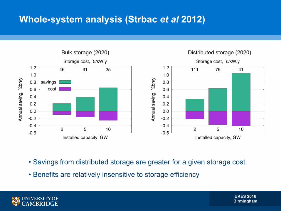
Whole-system analysis (Strbac et al 2012)
-0.6-0.4-0.20.00.20.40.60.81.01.2 46 31 25
2 5 10
Annu
al s
avin
g, ´£
bn/y
Installed capacity, GW
Storage cost, ´£/kW.y
savingscost
-0.6-0.4-0.20.00.20.40.60.81.01.2 111 75 41
2 5 10
Annu
al s
avin
g, ´£
bn/y
Installed capacity, GW
Storage cost, ´£/kW.y
Bulk storage (2020) Distributed storage (2020)
• Savings from distributed storage are greater for a given storage cost
• Benefits are relatively insensitive to storage efficiency

UKES 2016 Birmingham
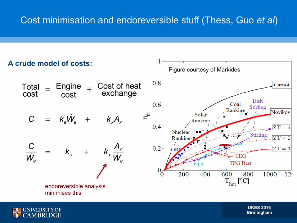
Cost minimisation and endoreversible stuff (Thess, Guo et al)
Totalcost = Engine
cost+ Cost of heat
exchange + Storagecost
C = keWe + kxAx + ks
Es
ρe
CWe
= ke + kxAxWe
+ kstd
ηe ρe
A crude model of costs:
endoreversible analysis minimises this
UKES 2016 Birmingham
Cost minimisation and endoreversible stuff (Thess, Guo et al)
Totalcost = Engine
cost+ Cost of heat
exchange + Storagecost
C = keWe + kxAx + ks
Es
ρe
CWe
= ke + kxAxWe
+ kstd
ηe ρe
A crude model of costs:
endoreversible analysis minimises this
Figure courtesy of Markides

UKES 2016 Birmingham
Endoreversible analysis: maximum power of CHE
Q1 = αh(Th −T1)
Q2 = α0(T2 −T0)
W.p eW
.
RHE
T
RHP
h
T0
T2
T1
T3
T4
ηe
* =WpQ1
= 1− T0
Th
Chambadal-Novikov efficiency:
Maximum normalised power:
ψe =
We
(αh +α0)T0
=( Th /T0 −1)2
4
Occurs at T1 /T2 = Th /T0 and α0 = αh
UKES 2016 Birmingham
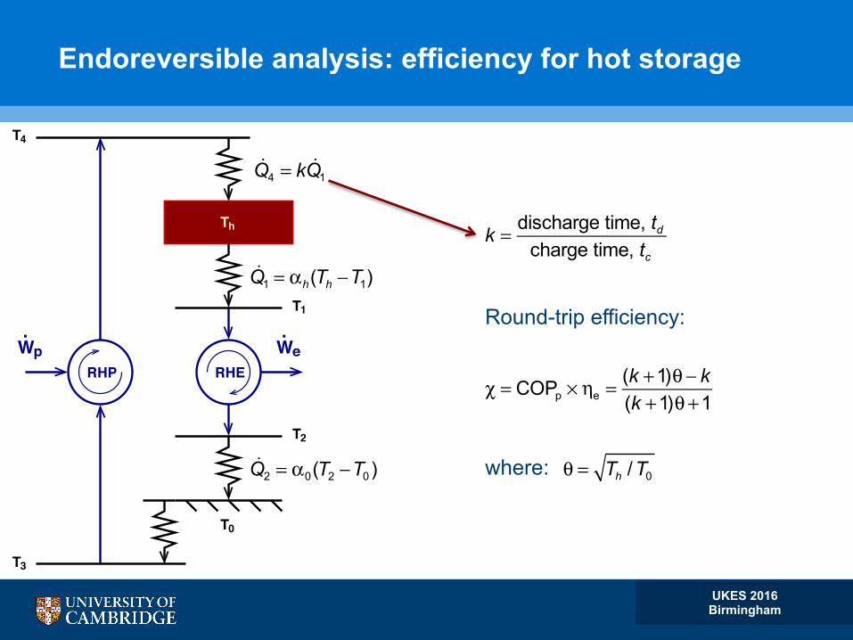
Q4 = k Q1
k = discharge time, td
charge time, tc
Round-trip efficiency:
χ = COPp × ηe =
(k +1)θ − k(k +1)θ +1
where:
θ = Th /T0
eW.p W
.
RHP
T
RHE
h
T0
T2
T1
T3
T4
Q1 = αh(Th −T1)
Q2 = α0(T2 −T0)
Endoreversible analysis: efficiency for hot storage
UKES 2016 Birmingham
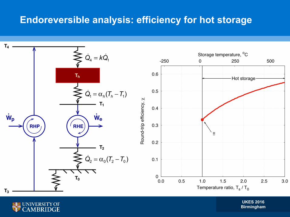
Q4 = k Q1
eW.p W
.
RHP
T
RHE
h
T0
T2
T1
T3
T4
Q2 = α0(T2 −T0)
Q1 = αh(Th −T1)
0
0.1
0.2
0.3
0.4
0.5
0.6
0.0 0.5 1.0 1.5 2.0 2.5 3.0
-250 0 250 500
Hot storage
!!R
ound
-trip
effi
cien
cy, r
Temperature ratio, Ts / T0
Storage temperature, oC
Endoreversible analysis: efficiency for hot storage

UKES 2016 Birmingham
Q3 = k Q2
Q1 = α0(T0 −T1)
Q2 = αc (T2 −Tc )
.p
.We
WRHP
RHE
3
T4
Tc
T1
T2
T0
T
0
0.1
0.2
0.3
0.4
0.5
0.6
0.0 0.5 1.0 1.5 2.0 2.5 3.0
-250 0 250 500
Hot storageCold storage
Rou
nd-tr
ip e
ffici
ency
, r
Temperature ratio, Ts / T0
Storage temperature, oC
Endoreversible analysis: efficiency for cold storage

UKES 2016 Birmingham
0.0
0.2
0.4
0.6
0.00 0.05 0.10
-175
-125
-75
100
300500
Rou
nd-tr
ip e
ffici
ency
, r
Normalised power output, se
HotCold
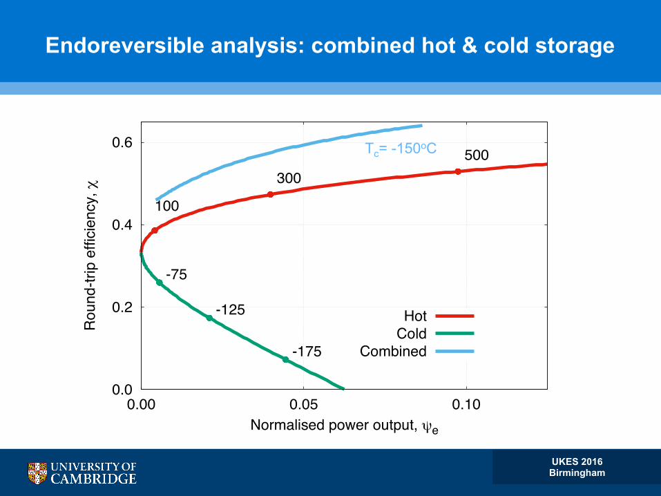
Endoreversible analysis: efficiency vs. power density
UKES 2016 Birmingham
Tc= -150oC
0.0
0.2
0.4
0.6
0.00 0.05 0.10
-175
-125
-75
100
300500
Rou
nd-tr
ip e
ffici
ency
, r
Normalised power output, se
HotCold
Combined
Endoreversible analysis: combined hot & cold storage

UKES 2016 Birmingham
Exergetic storage density (kWh / m3)
0
50
100
150
200
250
-250 -125 0 125 250 375 500
liquid N2
CAES
hotwaterPHS
PTEShot
PTEScold
Exer
getic
den
sity
, kW
h / m
3
Storage temperature, oC

UKES 2016 Birmingham
Isentropic’s “SVS” (Scaled Validation Model of PHES)
Hot and cold “layered” thermal stores for a 120 kW system
HOT (500 oC)
COLD (–150 oC)
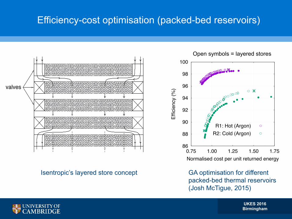
Efficiency-cost optimisation (packed-bed reservoirs)
UKES 2016 Birmingham
valves
86
88
90
92
94
96
98
100
0.75 1.00 1.25 1.50 1.75
Effic
ienc
y (%
)
Normalised cost per unit returned energy
R1: Hot (Argon)R2: Cold (Argon)
Isentropic’s layered store concept GA optimisation for different packed-bed thermal reservoirs (Josh McTigue, 2015)
Open symbols = layered stores

UKES 2016 Birmingham
Isentropic’s “SVS” : The Engine
Double-acting “reversible” reciprocating compressor / expander
HOT side
COLD side (below gallery)

UKES 2016 Birmingham
PTES is sensitive to all loss parameters (low “work ratio”)
50
60
70
80
90
100
0 5 10 15
Ther
mod
ynam
ic e
ffici
ency
, r
Pressure ratio, `
d = 0.99d = 0.95d = 0.90
50
60
70
80
90
100
0 25 50 75 100
Ther
mod
ynam
ic e
ffici
ency
, r
Pressure ratio, `
d = 0.99d = 0.95d = 0.90
Liquid PTES 2-stage A-CAES
χ = fn Pi , Ti , η j , εk , fl( )
heat exchange effectiveness
polytropic efficiencies pressure loss factors
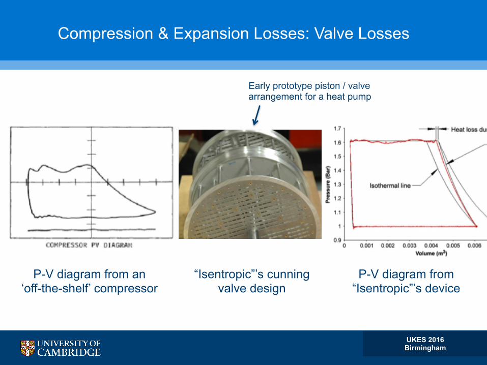
Compression & Expansion Losses: Valve Losses
P-V diagram from an ‘off-the-shelf’ compressor
“Isentropic”’s cunning valve design
P-V diagram from “Isentropic”’s device
UKES 2016 Birmingham
Early prototype piston / valve arrangement for a heat pump

Compression & Expansion Losses: Thermodynamic Losses
UKES 2016 Birmingham
10ï2 10 0 10 2 10 410ï3
10ï2
10ï1
10 0
10 1
Loss
Pe
CFD Air rv=6.8
CFD Helium r v=6.8
CFD Helium r v=2.0
Exp. Helium r v=2.0
isothermal adiabatic
slow fast

Load-Integrated Energy Storage (LIES)
UKES 2016 Birmingham
Electricity in
Electricity out
Refrigeration and / or cooling
Low-grade heating

More LIES
UKES 2016 Birmingham
-200
0
200
400
600
-0.4 -0.2 0
1
2
3
4
Tem
pera
ture
, C
Specific Entropy, KJ/kgK
T-s Diagram
Charge Discharge
-200
0
200
400
600
-0.4 -0.2 0
1
2
3
4
Tem
pera
ture
, C
Specific Entropy, KJ/kgK
T-s Diagram
Charge Discharge
Optimised for work output Lower discharge pressure
qout < 50 oC
qout < 50 oC qout > 75 oC

The UK’s Energy Storage Inventory (data from DOE)
UKES 2016 Birmingham
0.0
0.5
1.0
1.5
2.0
2.5
3.0
3.5
1963
1965
1974
1984
2006
2007
2008
2009
2010
2011
2012
2013
2014
2015
2016
Inst
alle
d ca
paci
ty, G
WPHS Mechanical Batteries
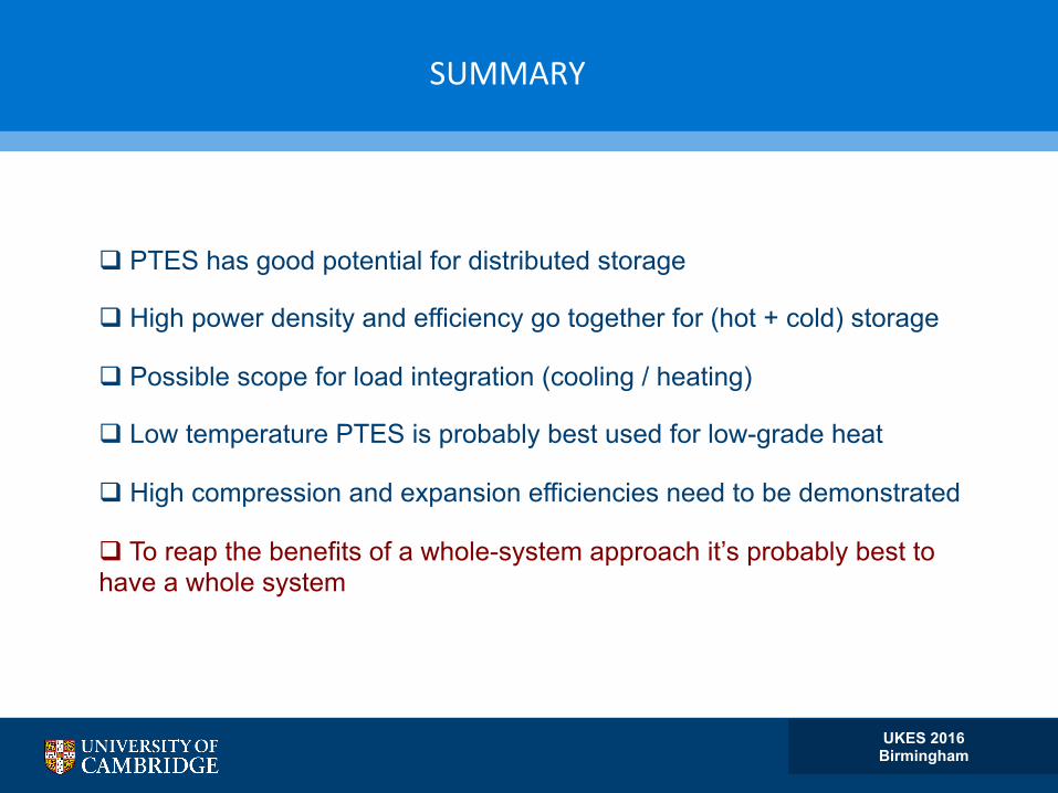
SUMMARY
q PTES has good potential for distributed storage
q High power density and efficiency go together for (hot + cold) storage
q Possible scope for load integration (cooling / heating)
q Low temperature PTES is probably best used for low-grade heat
q High compression and expansion efficiencies need to be demonstrated
q To reap the benefits of a whole-system approach it’s probably best to have a whole system
UKES 2016 Birmingham