pump 100 manual - knauer s u d e d n e t n 6i intended use hplc high pressure liquid chromatography...
TRANSCRIPT

Pump 100ManualV5010A

3
Table of contents
Note: For your own safety, be sure to read the manual and always observe the warnings and safety information on the device and in the manual!
Table of contents . . . . . . . . . . . . . . . . . . . . . . . . . . . . . . . . . . . . . . . . . . . . 3
Intended use . . . . . . . . . . . . . . . . . . . . . . . . . . . . . . . . . . . . . . . . . . . . . . . . 6Device types . . . . . . . . . . . . . . . . . . . . . . . . . . . . . . . . . . . . . . . . . . . . . . . . . . . 6Laboratory use . . . . . . . . . . . . . . . . . . . . . . . . . . . . . . . . . . . . . . . . . . . . . . . . . 7Where is it prohibited to use the device or system? . . . . . . . . . . . . . . . . . . . . . . 7
Features . . . . . . . . . . . . . . . . . . . . . . . . . . . . . . . . . . . . . . . . . . . . . . . . . . . 7
Safety . . . . . . . . . . . . . . . . . . . . . . . . . . . . . . . . . . . . . . . . . . . . . . . . . . . . . 8Laboratory regulations . . . . . . . . . . . . . . . . . . . . . . . . . . . . . . . . . . . . . . . . . . . 8Solvents . . . . . . . . . . . . . . . . . . . . . . . . . . . . . . . . . . . . . . . . . . . . . . . . . . . . . . 8PEEK connections . . . . . . . . . . . . . . . . . . . . . . . . . . . . . . . . . . . . . . . . . . . . . . . 9Protective measures . . . . . . . . . . . . . . . . . . . . . . . . . . . . . . . . . . . . . . . . . . . . . . 9Power supply and mains connection . . . . . . . . . . . . . . . . . . . . . . . . . . . . . . . . 10
Ground connection . . . . . . . . . . . . . . . . . . . . . . . . . . . . . . . . . . . . . . . . . . 10
Target group . . . . . . . . . . . . . . . . . . . . . . . . . . . . . . . . . . . . . . . . . . . . . . . . . . 10
Operating the device or system . . . . . . . . . . . . . . . . . . . . . . . . . . . . . . . . . 10
To what should the user pay particular attention? . . . . . . . . . . . . . . . . . . . . 10
What expertise should users have to safely operate a HPLC device or device sys-tem? . . . . . . . . . . . . . . . . . . . . . . . . . . . . . . . . . . . . . . . . . . . . . . . . . . . . . . 11
Symbols and labels . . . . . . . . . . . . . . . . . . . . . . . . . . . . . . . . . . . . . . . . . . 12
Installation . . . . . . . . . . . . . . . . . . . . . . . . . . . . . . . . . . . . . . . . . . . . . . . . 13
Packaging and transport . . . . . . . . . . . . . . . . . . . . . . . . . . . . . . . . . . . . . . . . . 13
Fastening material and shipping boxes . . . . . . . . . . . . . . . . . . . . . . . . . . . . 13
Protective film on the display . . . . . . . . . . . . . . . . . . . . . . . . . . . . . . . . . . . 13
Scope of supply . . . . . . . . . . . . . . . . . . . . . . . . . . . . . . . . . . . . . . . . . . . . . . . . 13
Pumps – device types . . . . . . . . . . . . . . . . . . . . . . . . . . . . . . . . . . . . . . . . . 13
Accessories . . . . . . . . . . . . . . . . . . . . . . . . . . . . . . . . . . . . . . . . . . . . . . . . . 13
Checking the scope of delivery . . . . . . . . . . . . . . . . . . . . . . . . . . . . . . . . . . 14
Space requirements . . . . . . . . . . . . . . . . . . . . . . . . . . . . . . . . . . . . . . . . . . . . . 14
Installation site . . . . . . . . . . . . . . . . . . . . . . . . . . . . . . . . . . . . . . . . . . . . . . . . 14
V5010A

4
Startup . . . . . . . . . . . . . . . . . . . . . . . . . . . . . . . . . . . . . . . . . . . . . . . . . . . 15
Operating modes . . . . . . . . . . . . . . . . . . . . . . . . . . . . . . . . . . . . . . . . . . . . . . 15
Isocratic . . . . . . . . . . . . . . . . . . . . . . . . . . . . . . . . . . . . . . . . . . . . . . . . . . . 15
HPG . . . . . . . . . . . . . . . . . . . . . . . . . . . . . . . . . . . . . . . . . . . . . . . . . . . . . . 15
Pump heads . . . . . . . . . . . . . . . . . . . . . . . . . . . . . . . . . . . . . . . . . . . . . . . . . . 15
Labeling on the pump heads . . . . . . . . . . . . . . . . . . . . . . . . . . . . . . . . . . . 15
Pump without pressure sensor . . . . . . . . . . . . . . . . . . . . . . . . . . . . . . . . . . . . . 16
Front view of the device . . . . . . . . . . . . . . . . . . . . . . . . . . . . . . . . . . . . . . . 16
Rear view of the device . . . . . . . . . . . . . . . . . . . . . . . . . . . . . . . . . . . . . . . . 16
Pump with pressure sensor . . . . . . . . . . . . . . . . . . . . . . . . . . . . . . . . . . . . . . . 17
Front view of the device . . . . . . . . . . . . . . . . . . . . . . . . . . . . . . . . . . . . . . . 17
Rear view of the device . . . . . . . . . . . . . . . . . . . . . . . . . . . . . . . . . . . . . . . . 17
Connecting the pump with other devices . . . . . . . . . . . . . . . . . . . . . . . . . . 18
Controlling the pump with chromatography software . . . . . . . . . . . . . . . . . . . 18
Local area network and automatic configuration . . . . . . . . . . . . . . . . . . . . . . . 18
Electrical connections . . . . . . . . . . . . . . . . . . . . . . . . . . . . . . . . . . . . . . . . . . . 18
Terminal strip: Remote . . . . . . . . . . . . . . . . . . . . . . . . . . . . . . . . . . . . . . . . . 19
ANALOG IN . . . . . . . . . . . . . . . . . . . . . . . . . . . . . . . . . . . . . . . . . . . . . . . . 20
START IN . . . . . . . . . . . . . . . . . . . . . . . . . . . . . . . . . . . . . . . . . . . . . . . . . . 20
STARTMODE . . . . . . . . . . . . . . . . . . . . . . . . . . . . . . . . . . . . . . . . . . . . . . . 21
Connecting the flat ribbon cable with the connector strip . . . . . . . . . . . . . . . . . . . . . . . . . . . . . . . . . . . . . . . . . . . . . . 21
Connecting the eluent line to the pump head . . . . . . . . . . . . . . . . . . . . . . . . . 22
Operating the pump . . . . . . . . . . . . . . . . . . . . . . . . . . . . . . . . . . . . . . . . . 23
Switch-on and self-test . . . . . . . . . . . . . . . . . . . . . . . . . . . . . . . . . . . . . . . . . . 23
Display of the pump . . . . . . . . . . . . . . . . . . . . . . . . . . . . . . . . . . . . . . . . . . 23
Overview of the function buttons . . . . . . . . . . . . . . . . . . . . . . . . . . . . . . . . 23
Communication interface . . . . . . . . . . . . . . . . . . . . . . . . . . . . . . . . . . . . . . . . 24
Setting the communication interface on the device . . . . . . . . . . . . . . . . . . 24
Setting the flow rate . . . . . . . . . . . . . . . . . . . . . . . . . . . . . . . . . . . . . . . . . . . . 24
Setting the flow rate manually on the device . . . . . . . . . . . . . . . . . . . . . . . 25
Setting the Pressure absorption . . . . . . . . . . . . . . . . . . . . . . . . . . . . . . . . . . . . 25
Setting the maximum and minimum pressure . . . . . . . . . . . . . . . . . . . . . . 25
Setting the power consumption . . . . . . . . . . . . . . . . . . . . . . . . . . . . . . . . . . . 26
Standard value for the maximum power consumption . . . . . . . . . . . . . . . . . . . . . . . . . . . . . . . . . . . . . . . . . . . . . . . 26
Setting the maximum and minimum for the power consumption . . . . . . . . 26
Starting and stopping the pump . . . . . . . . . . . . . . . . . . . . . . . . . . . . . . . . . . . 27
Purging the pump . . . . . . . . . . . . . . . . . . . . . . . . . . . . . . . . . . . . . . . . . . . 27
Purging the pump without pressure sensor . . . . . . . . . . . . . . . . . . . . . . . . . . . 28
Purge the pump with pressure sensor . . . . . . . . . . . . . . . . . . . . . . . . . . . . . . . 28
Piston backflushing . . . . . . . . . . . . . . . . . . . . . . . . . . . . . . . . . . . . . . . . . . . . . 28
Recommended cleaning solvents . . . . . . . . . . . . . . . . . . . . . . . . . . . . . . . . 28
Variant 1 . . . . . . . . . . . . . . . . . . . . . . . . . . . . . . . . . . . . . . . . . . . . . . . . . . . 29
Variant 2 . . . . . . . . . . . . . . . . . . . . . . . . . . . . . . . . . . . . . . . . . . . . . . . . . . . 29

5
Maintenance and care . . . . . . . . . . . . . . . . . . . . . . . . . . . . . . . . . . . . . . . . 30
Contact with the technical support hotline . . . . . . . . . . . . . . . . . . . . . . . . . . . 30
Maintenance contract . . . . . . . . . . . . . . . . . . . . . . . . . . . . . . . . . . . . . . . . . . . 30
What maintenance tasks may users perform on the device? . . . . . . . . . . . . . . 30
Tightening the screw fittings . . . . . . . . . . . . . . . . . . . . . . . . . . . . . . . . . . . . . . 30
Loosening the screw fittings . . . . . . . . . . . . . . . . . . . . . . . . . . . . . . . . . . . . . . 31
Leaks in the capillary screw fittings . . . . . . . . . . . . . . . . . . . . . . . . . . . . . . . . . 31
Replacing the pump head . . . . . . . . . . . . . . . . . . . . . . . . . . . . . . . . . . . . . . . . 31
Removing the pump head . . . . . . . . . . . . . . . . . . . . . . . . . . . . . . . . . . . . . 31
Installing the pump head . . . . . . . . . . . . . . . . . . . . . . . . . . . . . . . . . . . . . . 32
Exchanging the ball valves . . . . . . . . . . . . . . . . . . . . . . . . . . . . . . . . . . . . . . . 32
Removing the ball valves . . . . . . . . . . . . . . . . . . . . . . . . . . . . . . . . . . . . . . 33
Cleaning the ball valves . . . . . . . . . . . . . . . . . . . . . . . . . . . . . . . . . . . . . . . 33
Installing the ball valves . . . . . . . . . . . . . . . . . . . . . . . . . . . . . . . . . . . . . . . 33
Cleaning and caring for the device . . . . . . . . . . . . . . . . . . . . . . . . . . . . . . . . . 34
Environmental protection . . . . . . . . . . . . . . . . . . . . . . . . . . . . . . . . . . . . . 34
Disposal . . . . . . . . . . . . . . . . . . . . . . . . . . . . . . . . . . . . . . . . . . . . . . . . . . . . . 34
Decontamination . . . . . . . . . . . . . . . . . . . . . . . . . . . . . . . . . . . . . . . . . . . . 34
Storage . . . . . . . . . . . . . . . . . . . . . . . . . . . . . . . . . . . . . . . . . . . . . . . . . . . 34
Ambient storage conditions for the device . . . . . . . . . . . . . . . . . . . . . . . . . 34
Troubleshooting . . . . . . . . . . . . . . . . . . . . . . . . . . . . . . . . . . . . . . . . . . . . 35
Error list and solutions . . . . . . . . . . . . . . . . . . . . . . . . . . . . . . . . . . . . . . . . . . . 35
Technical data . . . . . . . . . . . . . . . . . . . . . . . . . . . . . . . . . . . . . . . . . . . . . . 37
Ambient conditions . . . . . . . . . . . . . . . . . . . . . . . . . . . . . . . . . . . . . . . . . . . . . 37
Pumps . . . . . . . . . . . . . . . . . . . . . . . . . . . . . . . . . . . . . . . . . . . . . . . . . . . . . . . 37
Delivery program . . . . . . . . . . . . . . . . . . . . . . . . . . . . . . . . . . . . . . . . . . . 39
Devices and accessories . . . . . . . . . . . . . . . . . . . . . . . . . . . . . . . . . . . . . . . . . . 39
Pump without pressure sensor . . . . . . . . . . . . . . . . . . . . . . . . . . . . . . . . . . 39
Pump with pressure sensor . . . . . . . . . . . . . . . . . . . . . . . . . . . . . . . . . . . . . 39
Spare parts . . . . . . . . . . . . . . . . . . . . . . . . . . . . . . . . . . . . . . . . . . . . . . . . . . . 40
Legal information . . . . . . . . . . . . . . . . . . . . . . . . . . . . . . . . . . . . . . . . . . . 41
Warranty Conditions . . . . . . . . . . . . . . . . . . . . . . . . . . . . . . . . . . . . . . . . . . . . 41
Manufacturer . . . . . . . . . . . . . . . . . . . . . . . . . . . . . . . . . . . . . . . . . . . . . . . . . 41
Transportation Damages . . . . . . . . . . . . . . . . . . . . . . . . . . . . . . . . . . . . . . . . . 41
Declaration of Conformity . . . . . . . . . . . . . . . . . . . . . . . . . . . . . . . . . . . . . 42
Abbreviations and terminology . . . . . . . . . . . . . . . . . . . . . . . . . . . . . . . . . 43
Table of figures . . . . . . . . . . . . . . . . . . . . . . . . . . . . . . . . . . . . . . . . . . . . . 44
Index . . . . . . . . . . . . . . . . . . . . . . . . . . . . . . . . . . . . . . . . . . . . . . . . . . . . 45
6 Intended use
Intended useHPLC High pressure liquid chromatography (HPLC) is a method for
separating substance mixtures, determining substances and measuring their concentration.
The device or device system is designed for high-pressure liquid chromatography. It is designed for laboratory use for analyzing as well as separating mixtures of fluid substances that can be dis-solved in a solvent or solvent mixture.
The pump is a conveying system for analytical and semi-prepar-ative applications. If bio-compatibility is required, titanium or ceramic pump head inlays can be used. The pump heads can be exchanged by the user.
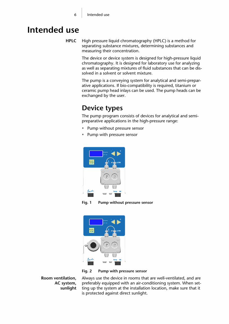
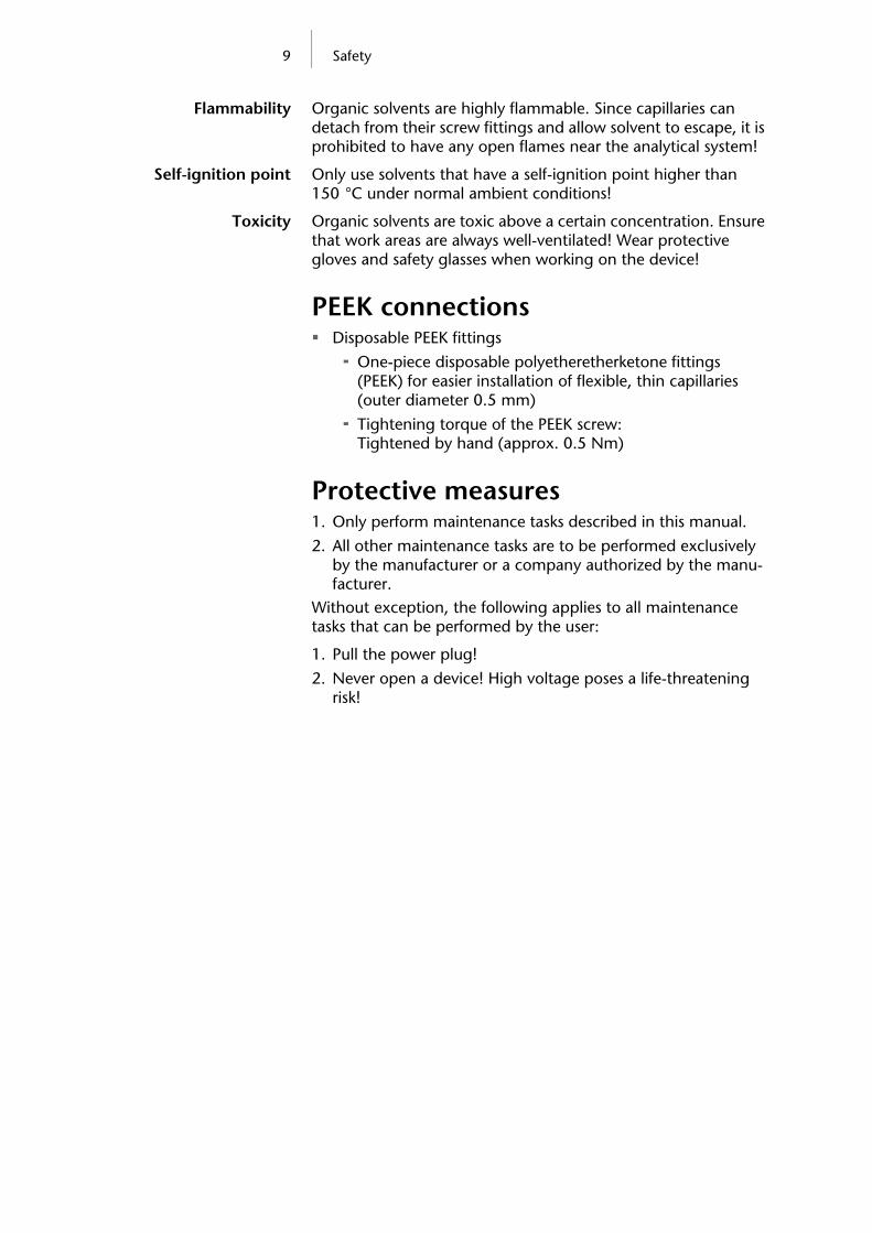
Device typesThe pump program consists of devices for analytical and semi-preparative applications in the high-pressure range:
Pump without pressure sensor
Pump with pressure sensor
Fig. 1 Pump without pressure sensor
Fig. 2 Pump with pressure sensor
Room ventilation, AC system,
sunlight
Always use the device in rooms that are well-ventilated, and are preferably equipped with an air-conditioning system. When set-ting up the system at the installation location, make sure that it is protected against direct sunlight.

7 Features
Checking intended use Only use the device for applications that fall within the range of the intended use. Alternatively, the protective and safety equipment of the device could fail.
Laboratory use Biochemical analyses
Chiral analyses
Food analyses
Pharmaceutical analyses
Environmental analyses
Where is it prohibited to use the device or system?Risk of explosion! Never use the device in potentially explo-sive atmospheres without appropriate protective equipment and approval by a notified body! Inform the technical support department of the manufac-turer.
Features Dual-piston technology
Liquid transport with low pulsation, stable flow rate and high flow accuracy
Long service life
Pump head with inlays made of stainless steel, titanium or ceramic
Piston backflushing
The pump with a pressure sensor can be integrated into an HPG system
High physical and chemical stability
Direct pump control via analog and digital signals
Control with chromatography software

8 Safety
Safety
Laboratory regulationsAdherence to
laboratory regulations Observe national and international regulations pertaining
to laboratory work!
Good Laboratory Practice (GLP) of the American Food & Drug Administration
For development of methods and validation of devices: Protocol for the Adoption of Analytical Methods in the Clinical Chemistry Laboratory, American Journal of Medical Technology, 44, 1, pages 30–37 (1978)
Accident prevention regulations published by the accident insurance companies for laboratory work
SolventsEven small quantities of other substances, such as additives, modifiers, or salts can influence the durability of the materials.
Note The list of selected solvents was compiled based on research in the pertinent literature and is only a recommendation. If there is any doubt, contact the technical support of the manufacturer.
Suitable eluents Less suitable eluents Not suitable eluents
Acetone
Acetonitrile
Benzene
Chloroform
Ethyl acetate
Ethanol
Hexane/heptane
Isopropanol
Carbon dioxide (liquid 99.999% CO2)
Methanol
Phosphate buffer solu-tions (0.5 M)
Toluol
Dilute ammonia solu-tion
Dilute acetic acid (10-50%), at 25° C
Dilute sodium hydrox-ide (1M)
Water
Dimethyl sulfoxide (DMSO)
Slightly volatile eluents
Methylene chloride
Tetrahydrofuran (THF)
Dilute phosphoric acid
Halogenated hydrocar-bons, e.g. Freon®
Concentrated mineral and organic acids
Concentrated bases
Eluents containing parti-cles
Perfluorinated eluents, e.g. Fluorinert® FC-75, FC-40
Perfluorinated polyether, e.g. Fomblin®
9 Safety
Flammability Organic solvents are highly flammable. Since capillaries can detach from their screw fittings and allow solvent to escape, it is prohibited to have any open flames near the analytical system!
Self-ignition point Only use solvents that have a self-ignition point higher than 150 °C under normal ambient conditions!
Toxicity Organic solvents are toxic above a certain concentration. Ensure that work areas are always well-ventilated! Wear protective gloves and safety glasses when working on the device!
PEEK connections Disposable PEEK fittings
One-piece disposable polyetheretherketone fittings (PEEK) for easier installation of flexible, thin capillaries (outer diameter 0.5 mm)
Tightening torque of the PEEK screw: Tightened by hand (approx. 0.5 Nm)
Protective measures1. Only perform maintenance tasks described in this manual.
2. All other maintenance tasks are to be performed exclusively by the manufacturer or a company authorized by the manu-facturer.
Without exception, the following applies to all maintenance tasks that can be performed by the user:
1. Pull the power plug!
2. Never open a device! High voltage poses a life-threatening risk!

10 Safety
Power supply and mains connection The device is intended for use with AC power networks of 100–240 V.
The supplied power cable is to be used in connection with the external power unit to connect the device to the mains supply.
Ground connectionThe ground connection for the pump has a designated hole with a thread M3 on the back of the device.
If the supplied power unit is used, than the ground connec-tion remains unused.
Please contact the technical support department of the man-ufacturer, if the pump along with other devices should be connected to the power supply with a 6-prong power unit; a pump needs to be grounded exclusively.
Caution! Contact the technical support of the manufac-turer if the pump should be connected with a multiple power unit of another manufacturer to the power supply. There is a risk of damaging the electronics.
Target group
Operating the device or systemThe device can be operated with chromatography software at the workstation or with the function buttons on the device.
To what should the user pay particular attention?To make your HPLC separations as efficient as possible, pay close attention to the following:
Avoiding additional dead volumes
1. Once they have been used, never re-use capillaries in other areas of the HPLC system.
2. Only use a given PEEK fitting for one specific port and never re-use it for other ports. Always install new PEEK fittings on each separate port.
Using special columns
When using special columns, follow the manufacturer's instructions on caring for the columns!
Checking for clogged capillaries
Regularly check for clogged capillaries – test back pressure without column!

11 Safety
Using filtered solvents 1. Use ultra-pure, filtered solvents for HPLC – gradient grade.
2. Filtration of substances under analysis
3. Use of inline filters.
The device open may only be opened by
the technical support department
Note: Only allow the technical support department of the manufacturer or a company authorized by the manu-facturer to open the devices for maintenance and repair work.
What expertise should users have to safely operate a HPLC device or device system? Completed degree as chemical laboratory technician
or comparable vocational training
Fundamental knowledge of liquid chromatography
Participation in an installation of the system performed by the manufacturer or a company authorized by the manufacturer, or suitable training on the system and chromatography soft-ware
Basic knowledge of Microsoft Windows®
Knowledge regarding substances that are suitable only to a limited extent for use in liquid chromatography

12 Symbols and labels
Symbols and labelsExplanations of symbols and labels on the device or system
Symbol Explanation
Hazard symbol indicating microelec-tronic devices that can be damaged by electrostatic discharge when touched.
CE (Conformité Européenne) mark for equipment that complies with the per-tinent EU directives and comes with a declaration of conformity from the manufacturer.
For your own safety, carefully read the manual and always observe the warn-ings and safety information on the device and in the manual!

13 Installation
Installation
Packaging and transportAt the factory, the device was carefully packed for safe transport.
Checking for signs of damage
during transport
Check the device for signs of damage that occurred during transport. If the shipment is incomplete or damaged, inform the manufacturer within three workdays. Also inform the freight car-rier about transport damage.
Fastening material and shipping boxesThe device is held in place and protected by foam inserts at the top and bottom. Please keep the transport box and the foam inserts.
Removing the packaging material
Remove the foam insert on the top of the device.
Remove device from packaging
Grip the device at its sides, near the front panel, and lift it out of the packaging.
Protective film on the displayDuring transport, a protective film prevents scratches on the dis-play of the device.
Removing the protective film
Remove the protective film from the display.
Scope of supply
Pumps – device types Pump with installed pump head and external power unit
Pump with installed pump head, pressure sensor and external power unit
Accessories Manual
External power unit
Cables
Power supply cable for Germany
Power supply cable for United Kingdom (optional)
Power supply cable for USA (optional)
Network cable
RS-232 port cable
Flat ribbon cables, 10-pin
Connector strip with stylus, 5-pin

14 Installation
Kit for bleeding the pump
Tools
Silicon tubing
Syringe 10 ml
1 x Screw fitting 1/8"
2 x Seal ring 1/8"
PTFE eluent filter
Snap ferrite
Use original parts and original accessories
Only use original parts and accessories made by the manufac-turer or a company authorized by the manufacturer.
Checking the scope of delivery1. Check whether the device and accessories are complete.
2. If a part is missing, inform the technical support department of the manufacturer.
Hotline of KNAUER Technical Support:
European hotline Languages: German and English Available by telephone: 8 a.m. to 5 p.m. (CET) Phone:+49 30 809727–0 Fax:+49 30 8015010
E-mail: E-mail: [email protected]
Space requirements Side clearance to other devices:
If there is a device on one side, min. clearance of 5 cm.
If there are devices on both sides, min. clearance of 10 cm.
At least 30 cm gap to the fan on the rear of the device.Note: Make sure that the power plug on the rear of the
device is always accessible, so that the device can be disconnected from the power supply.
Installation siteAmbient conditions of
the installation site Air humidity: Below 90% (non-condensing)
Temperature range: 4–40 °C; 39.2–104 °F
Sunlight: When setting up the device at the installation loca-tion, make sure that it is protected against direct sunlight.

15 Startup
Startup
Operating modes
Isocratic Analysis without gradients
The solvent composition is constant during the analysis.
The solvent can be recycled.
HPG The gradient is formed on the high-pressure side of the pump
(high-pressure gradient).
The pump is controlled by chromatography software.
Pump heads Pump head 10 ml, for use in analytical applications, standard
version made of stainless steel. Pump heads with titanium or ceramic inlays for biocompatible applications.
Pump head 50 ml, for use in semi-preparative applications, standard version made of stainless steel. Pump heads with titanium or ceramic inlays for biocompatible applications.
Labeling on the pump heads The front of the pump head is labeled with the specifications for the maximum pumping capacity (10 ml or 50 ml)and the mate-rial of the inlays (SS for stainless steel, Ti for titanium and C for ceramic).
Fig. 3 Labeling on the pump heads
Note: The manufacturer recommends that ceramic inlays always be used in pumps with pressure sensor.
Legend
A Labeling on pump head for the maxi-mum pumping capacity
B Labeling on pump head for the material of the inlays
AB

16 Startup
Pump without pressure sensor To disconnect the pump from the mains power,
disconnect the power plug.
Front view of the device
Fig. 4 Front view of the pump without pressure sensor
Rear view of the device
Fig. 5 Rear view of the pump without pressure sensor
LegendA Start/Stop key
B Display
C Function button 1
D Function button 2
E Pump head
C D
E
BA
LegendA CE mark
B Serial number
C Opening of the fan
D RS-232 port
E LAN connection
F Terminal strip: Remote
G Power connection – bushing
H Warning 1
I Hole for the ground connection
J Warning 2
A B
D
F
E
G
J I
C
H

17 Startup
Pump with pressure sensor To disconnect the pump from the mains power,
disconnect the power plug.
Front view of the device
Fig. 6 Front view of pump with pressure sensor
Rear view of the device
Fig. 7 Rear view of pump with pressure sensor
LegendA Start/Stop key
B Display
C Function button 1
D Function button 2
E Pump head
F Ventilation screw
G Pressure sensor
C
E
B D
FG
A
LegendA CE mark
B Opening of the fan
C Serial number
D RS-232 port
E LAN connection
F Terminal strip: Remote
G Power connection – bushing
H Warning 1
I Hole for the ground connection
J Warning 2
A B
D
F
E
G
J I
C
H

18 Connecting the pump with other devices
Connecting the pump with other devicesNote: The pump Smartline 100 is set to RS232 ex works.
Controlling the pump with chromatography softwareThe pump can be controlled individually or as part of a high-pressure gradient system or low-pressure gradient system by means of a computer and chromatography software.
Local area network and automatic configurationThe pump is controlled either by means of the function keys on the front of the device, or by means of the chromatography software.
Remote control Normally the pump is controlled by means of the chromatogra-phy software, via a local network (LAN).
Automatic configuration A pump connected to a local area network (LAN) is automati-cally recognized by the chromatography software.
Device status When used in a local area network (LAN), the system status of the pump can be verified by means of chromatography soft-ware.
LAN setting Ex works, the pump is set to DHCP (Dynamic Host Configura-tion Protocol). This means that the pump is automatically assigned an IP address within the local network.
Note: KNAUER recommends the automatic assignment of the IP address. Please inform the technical support of the manufacturer if the manual assignment of the IP address is necessary.
Electrical connections Use the Remote terminal strip to connect the pump with
external devices.
Use the LAN connection to connect the pump with external devices within a network.
Alternatively, connect the pump to a computer by means of the communication interface RS-232 port.
Caution! Electrostatic discharge can damage the electron-ics of the pump! Never touch the electric contacts of the Events and Remote terminal strips.

19 Connecting the pump with other devices
Terminal strip: Remote Sending and receiving start/control/error signals to and from
external devices.
Fig. 8 Terminal strip: Remote
Signal Explanation
GROUND Ground reference for start and error signals
START IN Connection for the short circuit (or TTL-low) to start and stop the operation of the pump.
ERROR IN/OUT Connection for an input or output of an error signal (open collector).
Example for the output:
Counter pressure to high
Pump stops due to a defectNote: Ex works, the pin is an error out-
put (0). In case of an error, it delivers a signal to e.g. the con-trolling computer. The Technical Support can change the pin from output to input.
ANALOG IN External control voltage (0–10 V) for con-trolling the flow rate, for example:
1 V for 1 ml/min in the case of the 10 ml pump head
1 V for 5 ml/min in the case of the 50 ml pump head
ANALOG OUT Analog output signal for reproducing the measured system pressure.
20 Connecting the pump with other devices
ANALOG INThe control of the flow rate by an external control voltage has to be prepared with a terminal program, for example with the Win-dows operating system program HyperTerminal:
Prerequisite The pump is connected to the power supply.
1. Windows Start All Programs Accessories Communication HyperTerminal.
2. Connect the pump using a LAN or RS-232.
3. Enter EXTCONTR:1 to control the flow rate externally using ANALOG IN.
4. Apply control voltage.
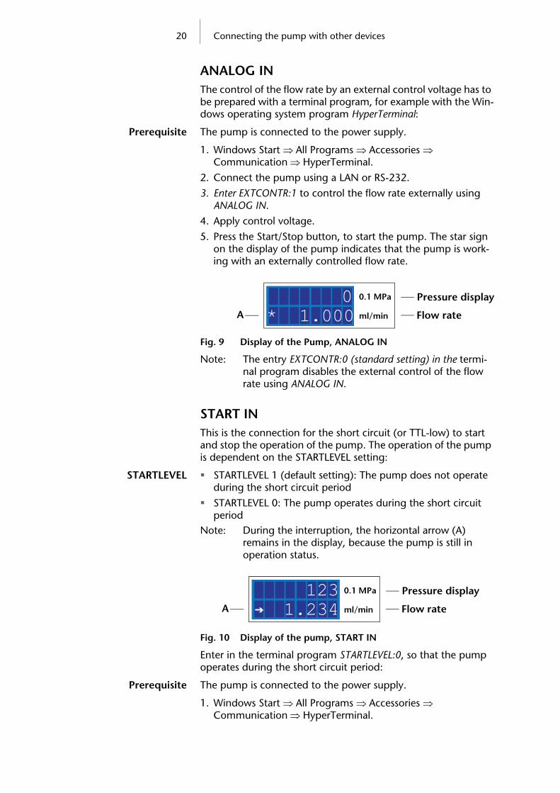
5. Press the Start/Stop button, to start the pump. The star sign on the display of the pump indicates that the pump is work-ing with an externally controlled flow rate.
Fig. 9 Display of the Pump, ANALOG IN
Note: The entry EXTCONTR:0 (standard setting) in the termi-nal program disables the external control of the flow rate using ANALOG IN.
START INThis is the connection for the short circuit (or TTL-low) to start and stop the operation of the pump. The operation of the pump is dependent on the STARTLEVEL setting:
STARTLEVEL STARTLEVEL 1 (default setting): The pump does not operate during the short circuit period
STARTLEVEL 0: The pump operates during the short circuit period
Note: During the interruption, the horizontal arrow (A) remains in the display, because the pump is still in operation status.
Fig. 10 Display of the pump, START IN
Enter in the terminal program STARTLEVEL:0, so that the pump operates during the short circuit period:
Prerequisite The pump is connected to the power supply.
1. Windows Start All Programs Accessories Communication HyperTerminal.
* 1.000 0
Flow rate
Pressure display
ml/min
0.1 MPa
A
Flow rate
Pressure display
ml/min
0.1 MPa
A 1.234 123

21 Connecting the pump with other devices
2. Connect the pump using a LAN or RS-232.
3. Enter STARTLEVEL:0.
STARTMODEBy default the pump is stopped and started using the Start/Stop button. The STARTMODE setting makes it possible that the pump is in operation directly after beeing connected to the power supply.
STARTMODE 0 (default setting): The pump does not operate directly after being connected to the power supply
STARTMODE 1: The pump operates directly after being con-nected to the power supply
Enter in the terminal program STARTMODE:1, so that the pump operates directly after being connected to the power supply:
Prerequisite The pump is connected to the power supply.
1. Windows Start All Programs Accessories Communication HyperTerminal.
2. Connect the pump using a LAN or RS-232.
3. Enter STARTMODE:1.
Connecting the flat ribbon cable with the connector stripTo enable signal transmission from external devices to the pump, the flat ribbon cable is connected with a connector strip and connected to the Remote terminal strip on the rear of the pump.
Flat ribbon cables with Connect the connector strip
Steps Figure
1. Place the connector strip (C) on a suitable surface.
2. Put the stylus (A) in the opening on the top of the connector strip and press downward.
3. Keep the stylus pressed down and insert the cable ends (B) into the front of the connector strip.
4. Remove the stylus.
5. Check whether the cables are tightly attached.
Fig. 11 Connecting the flat ribbon cable with the connector strip
A
B
C

22 Connecting the pump with other devices
Connecting the eluent line to the pump headNote: Make sure that the tapered side of the cutting ring
is pointed towards the fastening screw of the Teflon tube.
Connection eluent line at the pump head
Steps Figure
1. Push the Teflon tube (D) through the fas-tening screw (C) and the cutting ring (B).
2. Insert the tube end as far as possible into the inlet fitting (A) of the pump head.
3. Tighten the fastening screw by hand.
Fig. 12 Connect the eluent line to the pump head
BA
CD

23 Operating the pump
Operating the pumpNote: Operator errors and clogged capillaries can cause high
pressure spikes.
To avoid damage to the pump head, never allow the pump to run without liquid in the pump head and piston backflush-ing components.
Switch-on and self-testAfter the device is switched on, pump and the firmware version appear on the display. The device performs a self-test. After all tests have been successfully completed, the status of the pump with its current flow rate is displayed. The pump is ready for operation.
Switch-on and self-test Pump with external power unit:
1. Connect the external power unit to the power supply.
2. Connect the pump with the plug of the external power unit.
3. Wait until the pump has completed the self-test.Pump with housing extension:
1. Switch on the pump.
2. Wait until the pump has completed the self-test.
Display of the pump
Fig. 13 Display of the pump (50 ml) without pressure sensor
Fig. 14 Display of the pump (10 ml) with pressure sensor
Overview of the function buttons
Button Function Explanation
Function but-ton
Setting the values
Choosing the function
Setting the flow rate
Setting the maximum and minimum pres-sure
Selecting the com-munication interface
43.21 Flow rateml/min
1.234 123
Flow rate
Pressure display
ml/min
0.1 MPa
24 Operating the pump
Communication interface Terminal strip: Remote
RS-232
LAN
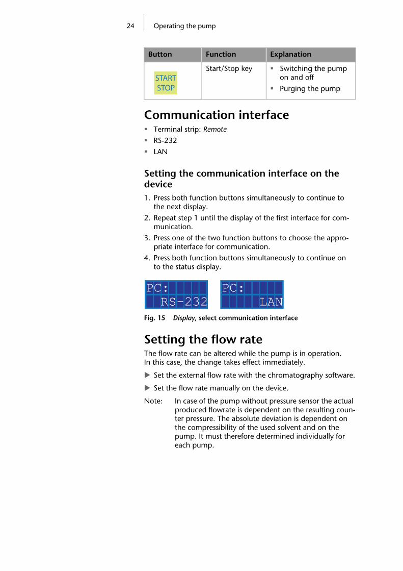
Setting the communication interface on the device1. Press both function buttons simultaneously to continue to
the next display.
2. Repeat step 1 until the display of the first interface for com-munication.
3. Press one of the two function buttons to choose the appro-priate interface for communication.
4. Press both function buttons simultaneously to continue on to the status display.
Fig. 15 Display, select communication interface
Setting the flow rateThe flow rate can be altered while the pump is in operation. In this case, the change takes effect immediately.
Set the external flow rate with the chromatography software.
Set the flow rate manually on the device.
Note: In case of the pump without pressure sensor the actual produced flowrate is dependent on the resulting coun-ter pressure. The absolute deviation is dependent on the compressibility of the used solvent and on the pump. It must therefore determined individually for each pump.
Start/Stop key Switching the pump on and off
Purging the pump
Button Function Explanation
START STOP
RS-232PC:
LANPC:

25 Operating the pump
Setting the flow rate manually on the device Press one of the two function buttons to adjust the value
of the current flow rate.
Practical tip! Hold down the function button to expedite changing the val-ues.
Setting the Pressure absorptionDue to the performance of the pump, intense pressures can build up in the bottom of the flow range.
Exceeding or undercutting the values for the maximum or mini-mum pressure leads to the pump being automatically shut-down.
1. Set maximum pressure to avoid damaging the pump or pump head.
2. Set minimum pressure to avoid running the pump dry.
Caution! Observe the permissible values for the maximum pressure depending on utilized pump head.
Setting the maximum and minimum pressureNote: If the minimum is set to 0, the minimum pump pres-
sure is not monitored.
In the display, the permissible maximum and minimum pressure of the pump is indicated by two vertical arrows (A).
Fig. 16 Display, set pressure limits
Setting maximum and minimum pressure
1. Press both function buttons simultaneously to continue to the next display.
2. Repeat step 1 until the pressure absorption is displayed.
3. Press one of the two function buttons to enter the desired value for the maximum pressure.
4. Press both function buttons simultaneously to reach the dis-play of the minimum pressure.
5. Press one of the two function buttons to enter the desired value for the minimum pressure.
6. Repeatedly press both function buttons simultaneously to return to the status display.
Note: Using a pump without a pressure sensor makes setting the pressure limits not possible.
A
9.876 123P
PMaximum pressure
Minimum pressure

26 Operating the pump
Setting the power consumptionThe power consumption is dependent on the flow rate and the counter pressure. At high flow rates and strong counter pres-sure, the power consumption increases.
Exceeding or undercutting the values for the maximum or mini-mum power consumption leads to the pump being automati-cally shutdown.
The settings for the minimum and maximum power consump-tion can be used as a protection against overpressure and run-ning dry of the pump without pressure sensor. These settings are much less accurate than the settings for the minimum and maximum pressure of the pump with pressure sensor.
Set the maximum power consumption to avoid damages to the pump as well as pump head during a blockage or uncon-trolled acceleration of the motors.
Set the maximum power consumption for the pump without pressure sensor to limit the pump pressure.
Set the minimum power consumption to avoid a dry run of the pump at highly reduced maximum power consumption (e. g. if leaking).
Note: The values for minimum and maximum power con-sumption are proportional values to the current strength.
Standard value for the maximum power consumptionThe pump is preset to a standard value for the maximum power consumption. Therefore the optimal value can only be empiri-cally determined from a sufficiently low value. The manufacturer recommends that with smaller flow rates the standard value for the maximum power consumption should be decreased.
Caution! Increase the standard value for the maximum power consumption only in small steps, if necessary.
Setting the maximum and minimum for the power consumptionNote: If the minimum is set to 0, the minimum power con-
sumption of the pump is not monitored.
In the display, the maximum and minimum power consumption of the pump is indicated by 2 vertical arrows (A).
Fig. 17 Display, power consumption
A
000 050I
IMaximum power consumption
Minimum power consumption
27 Purging the pump
Setting the maximum and minimum power
consumption
1. Press both function buttons simultaneously to continue to the next display.
2. Repeat step 1 until the power consumption is displayed.
3. Press one of the two function buttons to enter the desired value for the maximum power consumption.
4. Press both function buttons simultaneously to continue to the minimum power consumption.
5. Press one of the two function buttons to enter the desired value for the minimum power consumption.
6. Repeatedly press both function buttons simultaneously to return to the status display.
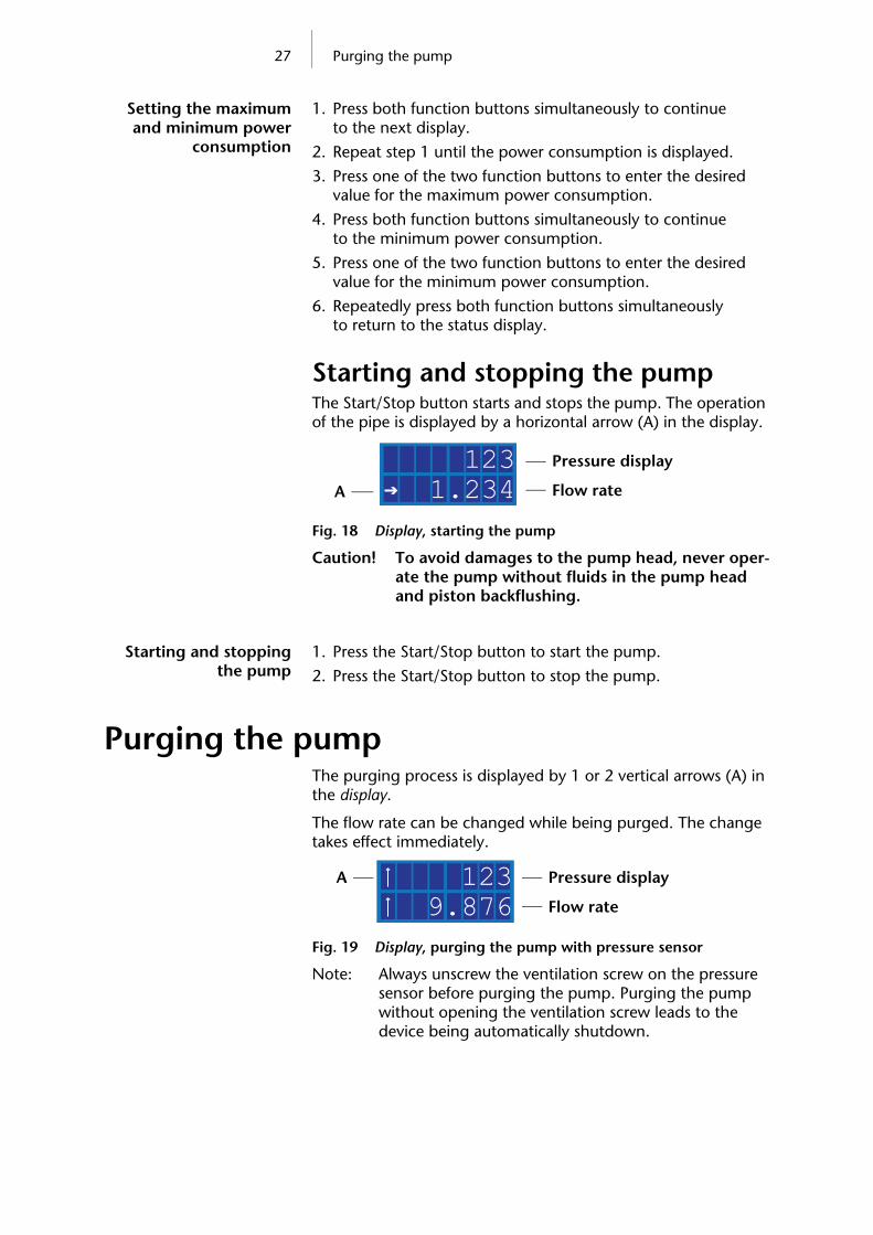
Starting and stopping the pumpThe Start/Stop button starts and stops the pump. The operation of the pipe is displayed by a horizontal arrow (A) in the display.
Fig. 18 Display, starting the pump
Caution! To avoid damages to the pump head, never oper-ate the pump without fluids in the pump head and piston backflushing.
Starting and stopping the pump
1. Press the Start/Stop button to start the pump.
2. Press the Start/Stop button to stop the pump.
Purging the pumpThe purging process is displayed by 1 or 2 vertical arrows (A) in the display.
The flow rate can be changed while being purged. The change takes effect immediately.
Fig. 19 Display, purging the pump with pressure sensor
Note: Always unscrew the ventilation screw on the pressure sensor before purging the pump. Purging the pump without opening the ventilation screw leads to the device being automatically shutdown.
1.234 123
A
Pressure display
Flow rate
9.876 123A Pressure display
Flow rate
28 Purging the pump
Purging the pump without pressure sensor1. Unscrew the outlet of the pump head to reduce counter
pressure when purging.
2. Place the vessel at the outlet of the pump head.
3. Hold the Start/Stop button for at least 1 second to start the purge function.
Purge the pump with pressure sen-sor1. Open the ventilation screw on the pressure sensor about a
half turn.
2. Hold the Start/Stop button for at least 1 second to start the purge function.
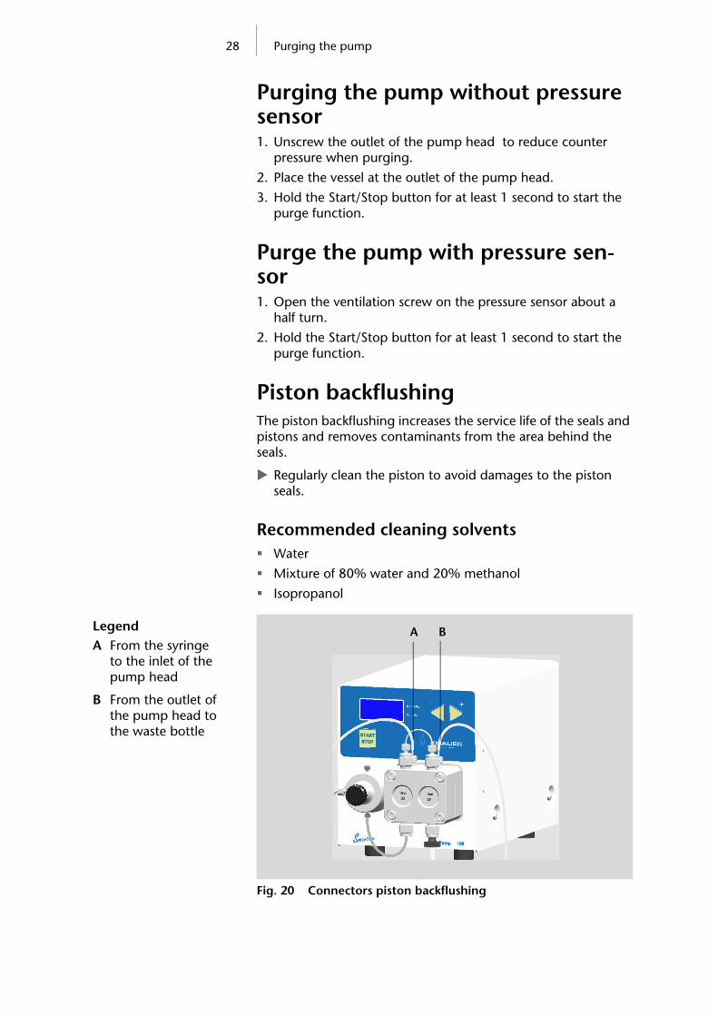
Piston backflushingThe piston backflushing increases the service life of the seals and pistons and removes contaminants from the area behind the seals.
Regularly clean the piston to avoid damages to the piston seals.
Recommended cleaning solvents Water
Mixture of 80% water and 20% methanol
Isopropanol
Fig. 20 Connectors piston backflushing
LegendA From the syringe
to the inlet of the pump head
B From the outlet of the pump head to the waste bottle
A B

29 Purging the pump
Variant 1Piston backflushing,
variant 11. Push two PTFE tubes onto the inlet and outlet of the pump
head.
2. Insert the tube end in a waste bottle.
3. Fill the syringe with water or another suitable flushing fluid.
4. Connect the syringe with the second tube end.
5. Squeeze flushing fluid with the syringe through the pump head until the fluid runs into the waste bottle without air bubbles.
6. After purging, remove both tubes from the inlet and outlet of the pump head.
7. Connect the inlet and outlet of the pump head with a piece of tube to avoid the solvent from evaporating and the piston chamber from drying out.
Variant 2Piston backflushing,
variant 21. Push a PTFE tube onto the outlet of the pump head.
2. Insert the tube end in a waste bottle.
3. Insert the second PTFE tube into a container with flushing fluid.
4. Suck in flushing fluid to the syringe and push the tube end onto the inlet of the pump head.
5. Place the container so that the entire flushing fluid flows slowly through the pump head due to gravity.
6. After purging, remove the tube from the inlet and outlet of the pump head.
7. Connect the inlet and outlet of the pump head with a piece of tube to avoid the solvent from evaporating and the piston chamber from drying out.
Note: Refill several times the container with flushing fluid to remove the residues of highly concentrated salt and buffer solutions.

30 Maintenance and care
Maintenance and careProper maintenance of your HPLC device will ensure successful analyses and reproducible results.
Contact with the technical support hotline
Contact data for KNAUER Technical
Support
If you have any technical questions regarding KNAUER hardware or software, please use one of the contact options below:
Hotline of KNAUER Technical Support:
European hotline Languages: German and English Available by telephone: 8 a.m. to 5 p.m. (CET) Phone: +49 30 809727–0 Fax: +49 30 8015010
E-mail: E-mail: [email protected]
Maintenance contractThe following maintenance work on the device may only be per-formed by the manufacturer or a company authorized by the manufacturer and is covered by a separate maintenance con-tract:
Opening the device or removing housing parts.
What maintenance tasks may users perform on the device?Users may perform the following maintenance tasks themselves:
Replacing the pump head
Exchanging the ball valves
Tightening the screw fittings1. Always tighten the inlet screw 1 (E) and the outlet screw 1 (B)
with a torque wrench and 15 Nm (pump head with ceramic inlays: 8 Nm).
2. Always hold the inlet fitting 1 (E) with a wrench when the capillary fitting (A) is being tightened with a wrench.
3. Using an Allen wrench, screw in the opposite pairs of fasten-ing screws (D) evenly and alternately to prevent the pump pistons on the inside from jamming.
31 Maintenance and care
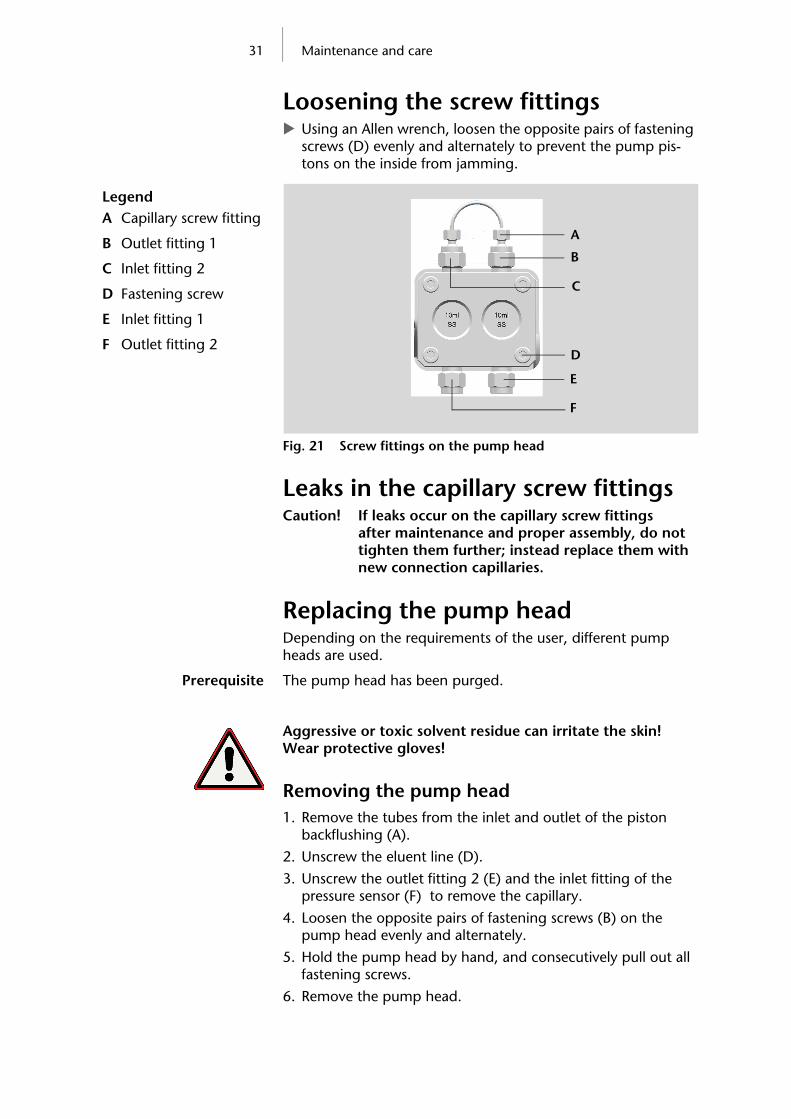
Loosening the screw fittings Using an Allen wrench, loosen the opposite pairs of fastening
screws (D) evenly and alternately to prevent the pump pis-tons on the inside from jamming.
Fig. 21 Screw fittings on the pump head
Leaks in the capillary screw fittingsCaution! If leaks occur on the capillary screw fittings
after maintenance and proper assembly, do not tighten them further; instead replace them with new connection capillaries.
Replacing the pump headDepending on the requirements of the user, different pump heads are used.
Prerequisite The pump head has been purged.
Aggressive or toxic solvent residue can irritate the skin! Wear protective gloves!
Removing the pump head1. Remove the tubes from the inlet and outlet of the piston
backflushing (A).
2. Unscrew the eluent line (D).
3. Unscrew the outlet fitting 2 (E) and the inlet fitting of the pressure sensor (F) to remove the capillary.
4. Loosen the opposite pairs of fastening screws (B) on the pump head evenly and alternately.
5. Hold the pump head by hand, and consecutively pull out all fastening screws.
6. Remove the pump head.
LegendA Capillary screw fitting
B Outlet fitting 1
C Inlet fitting 2
D Fastening screw
E Inlet fitting 1
F Outlet fitting 2
B
C
E
A
F
D

32 Maintenance and care
Fig. 22 Exchange the pump head
Installing the pump head1. Screw in the opposite pairs of fastening screws (B) evenly and
alternately.
2. Tighten all fastening screws evenly with an Allen key.
3. Screw in the capillary with outlet fitting 2 (E) and inlet fitting pressure sensor (F) and tighten with a wrench.
Exchanging the ball valvesNote: The ball and position of the valves have been harmo-
nized to each other. Insert the valves in the direction of flow!
Functional principle of the ball valve
Dirty ball valves do not open and close correctly. They cause pressure fluctuations and irregular flow.
Purge the pump head before changing the ball valve.
LegendA Inlet and outlet of the
piston backflushing
B Fastening screw
C Eluent line
D Outlet fitting 2
E Inlet fitting of the pressure sensor B
D
A
C
E
LegendA Ball valve
B Ball (dotted line)
C Flow direction (arrow)
BA
C

33 Maintenance and care
Removing the ball valvesNote: Loosen the screw fittings of the capillary connections
alternately, to prevent the capillaries from bending.
1. Unscrew the inlet fitting 2 (A) and capillary fitting (B).
2. Unscrew outlet fitting 1 (C).
3. Remove the ball valve.
4. Unscrew Inlet fitting 1 (E).
5. Remove the ball valve.
Fig. 23 Exchanging the ball valves
Cleaning the ball valves1. Put the valve in a beaker with rinsing solvent.
2. Put the beaker in an ultrasonic bath for at least 10 minutes.
Installing the ball valves1. Insert both ball valves.
2. Screw in the outlet fitting 1 (C) and tighten to 15 Nm with a torque wrench (pump head with ceramic inlays: 8 Nm).
3. Screw in the inlet fitting 1 (E) and tighten to 15 Nm with a torque wrench (pump head with ceramic inlays: 8 Nm).
4. Screw in the inlet fitting 2 (A) and capillary fitting (B) and tighten with a wrench.
LegendA Inlet fitting 2
B Capillary screw fitting
C Outlet fitting 1
D Ball valve
E Inlet fitting 1
B
C
D
E
A

34 Environmental protection
Cleaning and caring for the deviceRisk of electrical shock or short circuit if cleaning solution enters the device's interior! Moisten the cleaning cloth only slightly.All smooth surfaces of the device can be cleaned with a mild, commercially available cleaning solution, or with isopropanol.
Clean display The display of the devices can be cleaned with isopropanol and wiped dry with a soft, lint-free cloth.
Environmental protection
DisposalDrop the devices off at the local municipal waste facilities or send the devices back to the manufacturer where it will be dis-posed of properly.
DecontaminationContamination of devices with toxic, infectious or radio-active substances poses a hazard for all persons during operation, repair, sale and disposal of a device.
Danger caused by toxic, infectious, or radio-active sub-stances! A contaminated device must never be submitted for repairs, sold, or disposed of! Contract a specialist company to decontaminate the device or perform the decontamination yourself if you have the required expertise!All contaminated devices must be properly decontaminated by a specialist company or the operating company before they can be recommissioned, repaired, sold, or disposed of.
All materials or fluids used for decontamination must be col-lected separately and disposed of properly.
Storage
Ambient storage conditions for the deviceTemperature range: 4–40 °C; 39.2–104 °F
Air humidity: Below 90 % humidity (non-condensing)

35 Troubleshooting
TroubleshootingFirst measures for troubleshooting:
Check all screw fittings
Check whether air has gotten into the supply lines
Check device for leaksFurther measures:
Check errors against error list
Contact the technical support hotline of the manufacturer
Error list and solutions
Problem Solution
Pump will not turn on
The power cable must be connected to the power supply.
Inspect the power cable to ensure that it is plugged into the power supply
Inspect the plug on the rear side of the device
When purging, the pump switches off
The ventilation screw on the pressure sensor must be turned up.
Check if the ventilation screw on the pressure sensor is turned up.
Pump does not transport solvent
Check the following options:
Purge the pump head to remove the air bubbles
Inspect the eluent filter of the HPLC column and change when blocked
Exchange the pump head
Clean the ball valves
Exchange the ball valves
If the pump head seals are defective, solvent enters the piston backflush-ing; inform the technical support of the manufacturer.
36 Troubleshooting
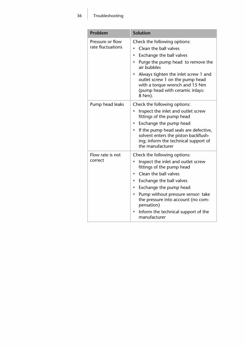
Pressure or flow rate fluctuations
Check the following options:
Clean the ball valves
Exchange the ball valves
Purge the pump head to remove the air bubbles
Always tighten the inlet screw 1 and outlet screw 1 on the pump head with a torque wrench and 15 Nm (pump head with ceramic inlays: 8 Nm).
Pump head leaks Check the following options:
Inspect the inlet and outlet screw fittings of the pump head
Exchange the pump head
If the pump head seals are defective, solvent enters the piston backflush-ing; inform the technical support of the manufacturer
Flow rate is not correct
Check the following options:
Inspect the inlet and outlet screw fittings of the pump head
Clean the ball valves
Exchange the ball valves
Exchange the pump head
Pump without pressure sensor: take the pressure into account (no com-pensation)
Inform the technical support of the manufacturer
Problem Solution

37 Technical data
Technical data
Ambient conditions
Pumps
Temperature range 4–40 ˚C; 39.2–104 ˚F
Air humidity below 90% humidity (non-condensing)
Conveying system Dual-piston pump with main and auxiliary piston
Flow rate range 10 ml pump head: 0.001–9.999 ml/min
50 ml pump head: 0.01–49.99 ml/min
Maximum pressure 10 ml pump head: 40 MPa up to 10 ml/min
50 ml pump head: 15 MPa up to 50 ml/min
Flow rate accuracy 10 ml pump head: ±1 % (1 ml/min)
50 ml pump head: ±2 % (1 ml/min)
For pumps dependent on pres-sure with out a pressure sensor
Flow rate precision Relative standard deviation RSD:< 0.5% (1 ml/min)
Gradients Isocratic HPLC pump
Expandable for the high pres-sure gradient system (HPG) with up to 4 eluents (controlled by software)
System protection Pump with pressure sensor:
Pmin and Pmax adjustable
Imin and Imax adjustable
Pump with pressure sensor: Imin and Imax adjustable

38 Technical data
Control LAN
RS-232
Terminal strip: Remote
Buttons on the device
Supply voltage range 100–240 V
Supply frequency 50-60 Hz
External power unit and power cable: Mains connection
24 V, 50 VA
Active power consump-tion
Maximum 40 W
IP protection class IP 20
Weight Pump without pressure sensor: 2.3 kg
Pump with pressure sensor: 2.4 kg
Dimensions (length x width x height)
Pump without pressure sensor: 220 x 110 x 130 mm
Pump with pressure sensor: 220 x 110 x 130 mm
39 Delivery program
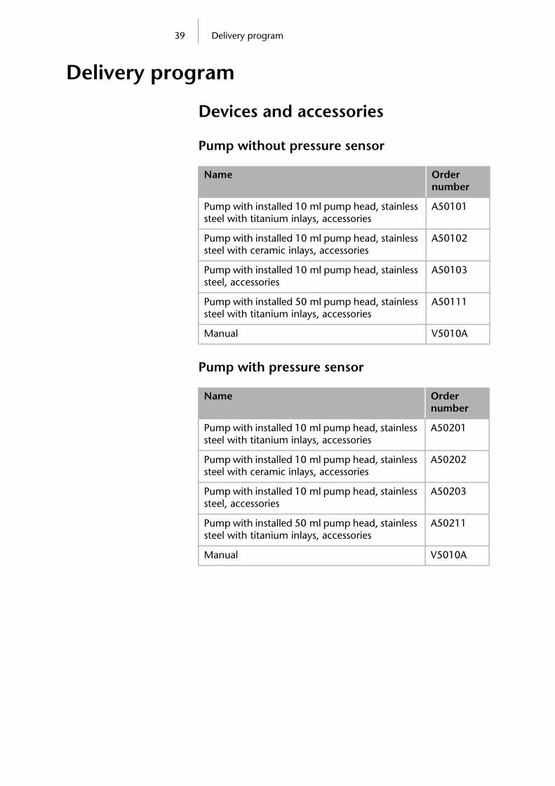
Delivery program
Devices and accessories
Pump without pressure sensor
Pump with pressure sensor
Name Order number
Pump with installed 10 ml pump head, stainless steel with titanium inlays, accessories
A50101
Pump with installed 10 ml pump head, stainless steel with ceramic inlays, accessories
A50102
Pump with installed 10 ml pump head, stainless steel, accessories
A50103
Pump with installed 50 ml pump head, stainless steel with titanium inlays, accessories
A50111
Manual V5010A
Name Order number
Pump with installed 10 ml pump head, stainless steel with titanium inlays, accessories
A50201
Pump with installed 10 ml pump head, stainless steel with ceramic inlays, accessories
A50202
Pump with installed 10 ml pump head, stainless steel, accessories
A50203
Pump with installed 50 ml pump head, stainless steel with titanium inlays, accessories
A50211
Manual V5010A

40 Delivery program
Spare parts
Name Order number
10 ml pump head, stainless steel A54103
10 ml pump head, stainless steel with titanium inlays
A54101
10 ml pump head, stainless steel with ceramic inlays
A54102
50 ml pump head, stainless steel with titanium inlays
A54111
Power supply cable M1479
Network cable A5255
Set of connector strips:2 x connector strip, 12-pos., stylus
A1420V12
2 x flat ribbon cable (1.5 m, 10-pos.) A1467
Ball valve A0684
Manual V5010A

41 Legal information
Legal information
Warranty ConditionsThe factory warranty for the device is valid for 12 months after the date of dispatch. All warranty claims shall expire in the event that any unauthorized changes are made to the device.
During the warranty period, any components with material or design-related defects will be replaced or repaired by the manu-facturer free of charge.
This warranty excludes the following:
1. Accidental or willful damage
2. Damage or errors caused by third parties that are not con-tractually related to the manufacturer at the time the damage occurs
3. Wear parts, fuses, glass parts, columns, light sources, cuvettes and other optical components
4. Damage caused by negligence or improper operation of the device and damage caused by clogged capillaries
5. Packaging and transport damageIn the event of device malfunctions, directly contact the manu-facturer.
ManufacturerWissenschaftliche Gerätebau Dr. Ing. Herbert KNAUER GmbH Hegauer Weg 38 14163 Berlin, Germany Phone: +49 30 809727-0 Fax: +49 30 8015010 E-Mail: [email protected] Internet: www.knauer.net
Transportation DamagesThe packaging of our devices provides the best possible protec-tion against transportation damage. Check the devices for signs of transportation damages. In case you notice any damage, con-tact the technical support and the forwarder company within three workdays.

42 Declaration of Conformity
Declaration of ConformityManufacturer name
and addressWissenschaftliche Gerätebau Dr. Ing. Herbert KNAUER GmbH Hegauer Weg 38 14163 Berlin, Germany
Pump S100 E4551V10, E4551V11, E4551V12, E4551V50, E4551V51, E4551V52, E4552V10, E4552V11, E4552V12, E4552V50, E4552V51, E4552V52
complies with the following requirements and product specifica-tions:
IEC 60799 (1998) Electrical accessories – Cord sets and inter-connection cord sets
IEC 61010-1 (2010 + Corrigendum: 2011) Safety require-ments for electrical equipment for measurement, control and laboratory use
Low voltage directive (2006/95/EC)
EN 61000-3-2 (2005 + A1:2008 + A2:2009) Electromagnetic compatibility (EMC) Part 3-2
EMC standarts (2004/108/EC)
EN 61326-1 (2006) Electrical equipment for measurement, control and laboratory use – EMC requirements
EN 61326-1 Corrigendum 2 (2010)
Directives for an environmentally sound use of electrical and electronic equipment
RoHS directives 2002/95/EC (2003) and 2011/65/EU on the restriction of the use of certain hazardous substances in electrical and electronic equipment
WEEE directive 2002/96/EC (2003) on waste electrical and electronic equipment
The device was tested with a typical configuration.
Berlin, 2012-12-14
Dr. Alexander Bünz (Managing Director)
The mark of conformity has been applied to the rear panel of the device.

43 Abbreviations and terminology
Abbreviations and terminologyHere you can find information on the abbreviations and termi-nology used in this manual.
Terminology Explanations
GLP Good Laboratory Practice – quality assurance for laboratories.
HPG High Pressure Gradient (HPG) Operating mode of an HPLC system. The solvent is mixed on the high pressure side of the pump.
HPLC High Pressure Liquid Chromatography (HPLC).
Remote The chromatography software controls the pump.
Solvent Mobile phase (eluent) or carrier for liquid chromatography

44
Table of figuresFig. 1: Pump without pressure sensor . . . . . . . . . . . . . . . . . . . . . . . . . . . . . 6Fig. 2: Pump with pressure sensor . . . . . . . . . . . . . . . . . . . . . . . . . . . . . . . . 6Fig. 3: Labeling on the pump heads . . . . . . . . . . . . . . . . . . . . . . . . . . . . . . 15Fig. 4: Front view of the pump without pressure sensor . . . . . . . . . . . . . . . 16Fig. 5: Rear view of the pump without pressure sensor . . . . . . . . . . . . . . . 16Fig. 6: Front view of pump with pressure sensor . . . . . . . . . . . . . . . . . . . . 17Fig. 7: Rear view of pump with pressure sensor . . . . . . . . . . . . . . . . . . . . . 17Fig. 8: Terminal strip: Remote . . . . . . . . . . . . . . . . . . . . . . . . . . . . . . . . . . . 19Fig. 9: Display of the Pump, ANALOG IN . . . . . . . . . . . . . . . . . . . . . . . . . . 20Fig. 10: Display of the pump, START IN . . . . . . . . . . . . . . . . . . . . . . . . . . . . 20Fig. 11: Connecting the flat ribbon cable with the connector strip . . . . . . . . 21Fig. 12: Connect the eluent line
to the pump head . . . . . . . . . . . . . . . . . . . . . . . . . . . . . . . . . . . . . . 22Fig. 13: Display of the pump (50 ml) without pressure sensor . . . . . . . . . . . 23Fig. 14: Display of the pump (10 ml) with pressure sensor . . . . . . . . . . . . . . 23Fig. 15: Display, select communication interface . . . . . . . . . . . . . . . . . . . . . 24Fig. 16: Display, set pressure limits . . . . . . . . . . . . . . . . . . . . . . . . . . . . . . . . 25Fig. 17: Display, power consumption . . . . . . . . . . . . . . . . . . . . . . . . . . . . . . 26Fig. 18: Display, starting the pump . . . . . . . . . . . . . . . . . . . . . . . . . . . . . . . 27Fig. 19: Display, purging the pump with pressure sensor . . . . . . . . . . . . . . . 27Fig. 20: Connectors piston backflushing . . . . . . . . . . . . . . . . . . . . . . . . . . . 28Fig. 21: Screw fittings on the pump head . . . . . . . . . . . . . . . . . . . . . . . . . . 31Fig. 22: Exchange the pump head . . . . . . . . . . . . . . . . . . . . . . . . . . . . . . . . 32Fig. 23: Exchanging the ball valves . . . . . . . . . . . . . . . . . . . . . . . . . . . . . . . 33

45
IndexAAbbreviations 43AC system 6Accessories 13Additives 8Ambient conditions 14
BBall valvescleaning 33exchanging 32installing 33removing 33
CCare 30, 34CE marking, see Declaration of conformity 42Chromatography software 18Cleaning 34Communicationinterfaces 24
Contact 30Controlling the pump 18, 23
DDead volume 10Declaration of Conformity 42Decontamination 34Delivery program 39Disconnecting from power supply 14Disposal 34
EElectrical connections 19remote terminal strip 18
Eluent lineconnecting the pump head 22
Eluents 8Environmental protection 34Explosion hazard 7
FFeatures 7Filter 11Fittingstightening 30
Flammability 9Flashpoint, see self-ignition point 9Function buttons 23
GGradient grade, filtered solvent 11
HHotline 30Europe 14
HPGmode 15
HPLC Systemoperation 10
IInstallation 13Installation site 14Isocraticmode 15
LLabeling, pump head 15Laboratory regulations 8Laboratory use 7LAN 18Leakson capillary screw fittings 31
MMains connection 10ground connection 10
Maintenance 30by user 30maintenance contract 30
Manufacturer 41Markings 12ModeHPG 15isocratic 15
Modifiers 8Module safety 8
OOperating mode 15Operationdevice 10
Original accessories 13

46
PPEEK connection 9Piston backflushing 28Power plug 14Power supply 10Protective film 13Protective measures 9Pumpdevice types 6pump with pressure sensor, version A 17pump without pressure sensor, external
power supply 16Pump control 23Pump head 15exchanging 31installing 32labeling 15removing 31
Purging the pump 27with pressure sensor 28without pressure sensor 28
RRemote terminal strip 19Room ventilation 6
SSafety 8Salts 8Scope of delivery 13Screw fittingsloosening 31
Self-ignition point 9Self-test 23Setting the flow rate 24Setting the power consumption 26maximum 26minimum 26
Setting the pressure sensor 25maximum 25minimum 25
Solventtoxicity 9
Solvents 8, 9Space requirements 14Startup 15Sunlight 6Switch-on 23Symbols 12
TTarget group 10Technical data 37Technical support 30Toxicity 9solvent 9
Transportation damages 41Troubleshooting 35
UUse, intended 6User 10
WWarnings 8Warranty 41

Wissenschaftliche GerätebauDr. Ing. Herbert Knauer GmbHAll rights reserved.The information in this document is subject to change without prior notice.Translation of the original German edition of this manual.2012-12-14Printed in Germany on environmentally friendly paper from sustainable forests.
©
See up-to-date manuals online:www.knauer.net/downloads
HPLC · SMB · Osmometry
Wissenschaftliche GerätebauDr. Ing. Herbert Knauer GmbHHegauer Weg 3814163 Berlin, Germany
Phone: +49 30 809727-0Telefax: +49 30 8015010E-Mail: [email protected]: www.knauer.net
www.knauer.net
© KNAUER 2012 V5010A/0.1/12.12/Koe