puma iii maintenance manual - the rhinestone world
TRANSCRIPT

Important Safety Information
Safety InstructionsGeneral and Personal Safety Precautions
[PERSONAL SAFETY]For personal safety, observe the following general precautions: A second person should be available to disable the system in an emergency. Wear appropriate protectIIIe gear that fits comfortably. Do not wear loose-fitting clothes. If you are wearing a long-sleeved shirt, fold the
cuffs up your arm. Never wear gloves close to moving parts. Necklaces, ties and scarves should be tucked inside shirts. Long hair should be covered.
[ELECTRICAL TOOL SAFETY]When using Electrical Tools make sure to: Use tools that are in good operating order. Any tool that appears electrically or
Mechanically faulty must be labeled and sent immediately for repair. Make sure that you are electrically insulated when using electrical tools. Wear
rubber-soled shoes and stand on a dry surface. If, during the use of electrical equipment, you feel an electrical discharge (e.g. a
tickling sensation on your skin) immediately stop using that tool. Label it, and send it forrepair.
[GENERAL SITE SAFETY REQUIREMENTS] Fire extinguishers must be in working order and within easy reach. The main power supply switch must be easily accessible. The system site must be suitably illuminated from all sides. Before operation, carefully read the warning labels on your Cutting plotter unit as
well as the cautions and warnings in this manual. Connect the Cutting plotter to a properly grounded power outlet. Make sure the
voltage level of the Cutting plotter matches that of the power source. Don’t dissemble the unit while system power is on since the power supplies inside
contain high voltage. Never leave the machine unattended during operation. Follow the instructions on maintaining and cleaning your system. Not only will this
enable you to utilize your machine efficiently, but it will also ensure that yourmachine runs safely.
Important Safety Information

Contents
Important Safety Information.................................................... iSafety Instructions ........................................................................................................ i
General and Personal Safety Precautions ............................................................ i
Contents IIIIntroduction and Component Overview................................. III
Main Unit Assembly Puma IIII ............................................................................ vElectronic and Electrical Assembly ......................................................................Left End Assembly................................................................................................Right End Assembly .............................................................................................X Motor Bracket and Belt Assembly ....................................................................Tool Carriage Assembly........................................................................................Carriage Belt Idle-Pulley Assembly......................................................................Pinch Roller Assembly..........................................................................................Grid Drums Assembly ..........................................................................................
System Diagram and Components of Main Board ................ 1System Diagram ................................................................................................. 2Puma Wiring Diagram.................................................. 錯誤! 尚未定義書籤。
Maintenance 4Components Replacement and Belt Tension Adjustment............................................ 4
Removing the Front, Back, End and Top Covers ............................................... 4Replacing the Pinch Roller Sets.......................................................................... 5Replacing the Tool Carriage ............................................................................... 8Replacing the Y-Motor.......................................................................................11Replacing the VCM PC Board.......................................................................... 13Main board Connection or Replacement .......................................................... 14Replacement of Fuses ....................................................................................... 15Adjusting the Tool Carriage Transmission Belt ................................................ 16Adjusting the X Motor Tension Belt................................................................. 17Adjusting The Y Motor Tension Belt ................................................................ 18
Troubleshooting 27Maintenance Diagnostics........................................................................................... 27
To the Contents Page ........................................................................................ 27How to Begin Maintenance Diagnostics........................................................... 27Diagnostic Test for SRAM and DRAM............................................................ 29Diagnostic Test for Lever Sensor...................................................................... 29Diagnostic Test for Width Sensor ..................................................................... 31Diagnostic Test for Motor Encoder and Tool Holder Encoder ......................... 31Diagnostic Test for Tool Force (VCM) ............................................................. 33Diagnostic Test for Motor Movement............................................................... 33Diagnostic Test for the RS-232 Interface.......................................................... 34
Problems and Solutions ............................................................................................. 35
Appendix 39Puma Parts & Accessory List .......................................................................... 40Spare Parts Reordering Form............................................................................ 41
Contents

Introduction and ComponentOverview
This Maintenance Guide provides step-by-step instructions for replacing and maintaining thecomponents of the Puma Cutting plotter. It also includes a troubleshooting chapterwith some handy hints when problems arise or if the plotter does not operate properly.This Maintenance Guide provides system diagrams, wiring diagrams and numerous flowcharts detailing the maintenance diagnostics built into the Puma Cutting plotter. Finallythere is a parts list and spare parts order form for convenience of ordering replacement parts.
For further Tech Support enquiries and assistance please contact the following Emailaddress:
The following diagrams represent all of the maintainable mechanical and electroniccomponents of the Puma Cutting Plotter with corresponding parts lists for convenientidentification.
To the Contents Page

Puma IIII Main UnitAssembly

PumaIIIIModel Table1.1PartsListoftheMainunitassemblyItem Parts Number Parts Name Quantity
124401210G Unit base box 1
224402393G Side support left 1
324402394G Side support right 1
429004688G Main Beam Assembly 1
522800705G Top rail 1
622801070G Square Bar 1
729001437G Pinch roller assembly 2
829004690G Carriage assembly 1
922802168G Top cover 1
1024100499G Left Cover 1
1124100491G Right Cover 1
1224100492G Front platen extention 1
1324100493G Rear platen extension 1
1424100333G Puma Lever. 1
1529005498G RoHs Main board for Cutter all series assembly 1
1629004692G Control panel Assembly 1
Introduction and Component Overview

Puma IIII Electronic and Electrical Assembly

BK07302A Puma III Model Table 2.1 Parts List for the Puma Model
Item Parts Number Parts Name Quantity
124401210G Unit base box 1
229005498G RoHs Main board for Cutter all series assembly 1
329001488G Power board 1
425700075G ON/OFF Power Switch (K/3C) 1
522300021G Fuse Holder Type3A/250V(K/3C) 1
621800034G AC PLUG (including EMI Filter ) (K/3C) 1
Introduction and Component Overview
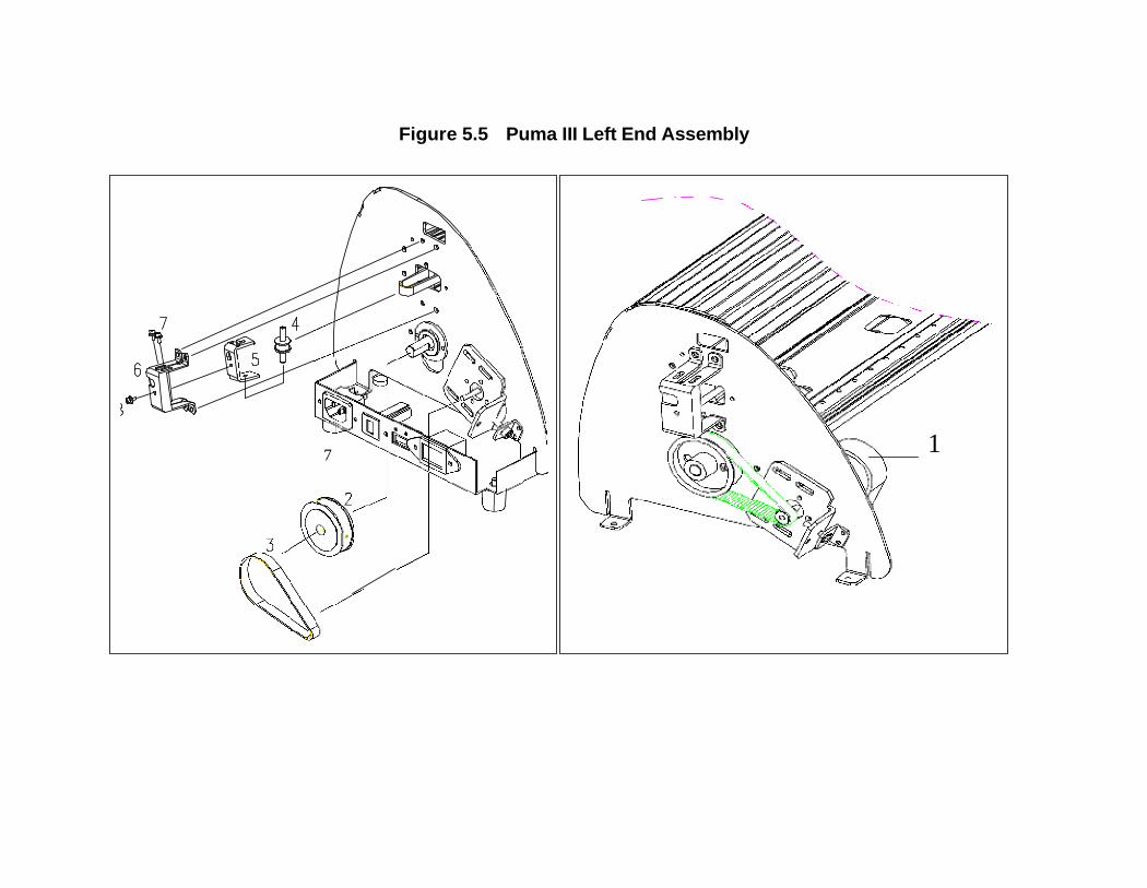
Figure 5.5 Puma III Left End Assembly
7 1

Puma III 60 Model Table 5.4 Puma III Left End Assembly
Number Part Number Description PiecesStandard
Amount1 BK02048B X-Axis Motor Assembly (Puma 60) SET 1
2 PL02029A X axis actively belt gear PCS 1
3 BL02203A X-axis belt Puma III 132(2GT-W10-L224)
PCS 1
4 PL02010A Idle pulley PCS 1
5 PS02223A Idle pulley ass'y adjusting bracket PCS 1
6 PS02222A Idle pulley ass'y bracket PCS 1
7 FU00004A Fuse Holder Type. PCS 1

Figure 5.5 Puma III Right End Assembly
7
8

Puma III 60 Model Table 5.5 Puma III Right End Assembly
Number Part Number Description PiecesStandard
Amount1 PS02007A Active pulley’s bracket PCS 1
2 PL02011A Active pulley PCS 1
3 LH02011B Active pulley 's shaft PCS 1
4 PS00818A Cable basket. PCS 1
5 PS02008A Y-motor bracket PCS 1
6 BK02009C Y Motor ass'y SET 1
7 PLC2008B Switch Cam PCS 1
8 SW00010A Lever Switch PCS 1

Puma III Carriage Assembly
Item Parts Number Parts Name Quantity
122802177G carriage base finishing 1
222800769G Right-Slide shaft in tool carriage. 1
322800765G Left-Slide shaft in tool carriage. 1
420200085G Blade holder slide bracket assembly 1
529000940G VCM Assembly. 1
620200065G VCM coil. 1
725500043G Tool carriage spring. 2
829001467G VCM PCB Assembly 1
922800838G Blade holder bracket screw 1
1022800048G Spacer for carrier guide roller(A Type). 2
1120700040G Flange Bearing MF74ZZ. 4
1222801680G Carrier Guide Roller Flute-A Type(White) 2
1322800049G Carrier guide roller(A type)shaft. 2
1422800411G Spacer for carrier guide roller(DU type). 2
1520700029G Bearing L-840ZZ/MR84ZZ 4
1622800710G Carrier guide roller flute-DU Type. 4
1722801464G White spring bracket for carrier guide roller 2
1825500041G Spring for carrier guide roller. 4
1922800717G Carrier guide roller(DU type)shaft. 2
2029004514G AASIIIcarriage board assembly 1
2129005382G AASIII sensor assembly with braket 1

Puma III X Motor Bracket and Belt Assembly
Figure 6. X motor bracket and belt assembly
Introduction and Component Overview

BK07024B Puma III Model Table 6 The Parts List of the X-motor assembly.
Number Part Number Description Pieces StandardAmount6.
1BK07022B Motor assembly, Puma. SET 1
6.1.1
MT00101B Motor MS090600, Puma. PCS 16.1.2
DS00003C Motor pulley, 2GT-P18, Puma. PCS 16.1.3
SCM04003511 Headless Screw, M4x3.5. PCS 16.1.4
EZ00505A Cable Tie, YJ-160. PCS 16.2
PS07013A X-motor bracket, Puma. PCS 16.3
PS00502B X-motor adjusting bracket, Puma. PCS 16.4
SCM04020T2-STruss head screw & spring washer, M4x20. PCS 16.5
SCM04010T2-SF
Truss head screw & spring & flat washer,M4x10.
PCS 66.6
SCI10108P2-S Pan head screw & spring washer, #6x8. PCS 4
Introduction and Component Overview
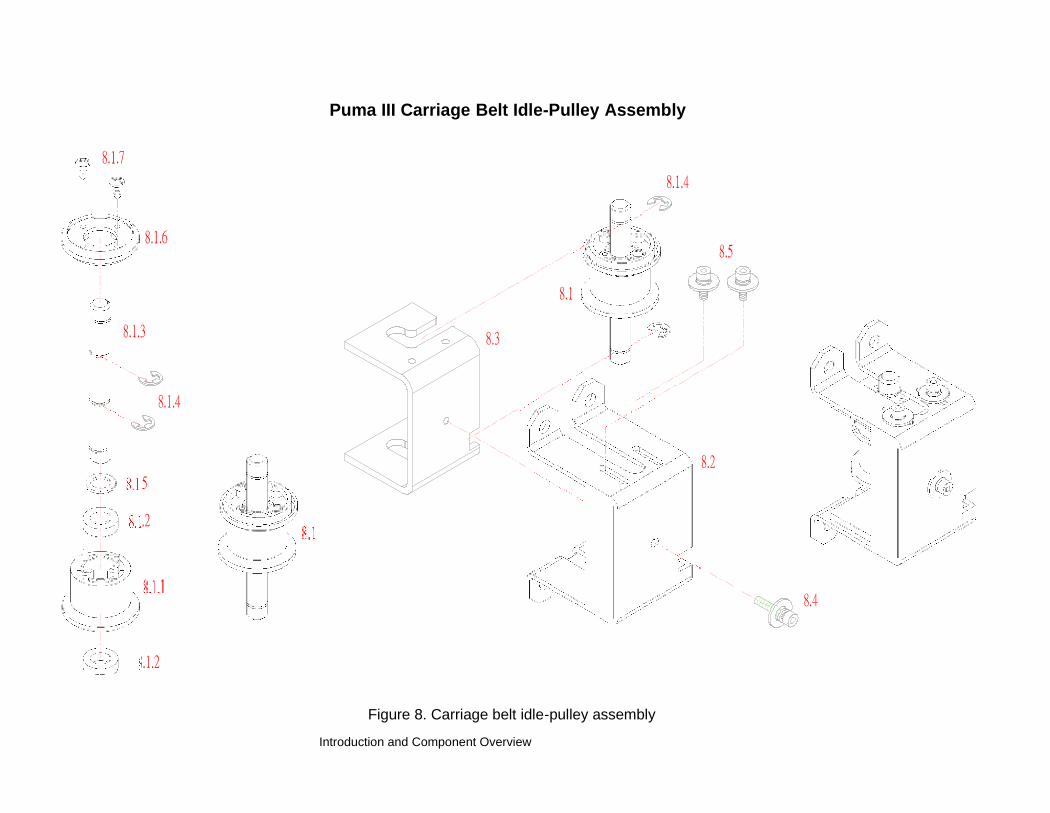
Puma III Carriage Belt Idle-Pulley Assembly
Figure 8. Carriage belt idle-pulley assembly
Introduction and Component Overview

BK07011A Puma III Model Table 8 The Parts List of the Complete idle pulley assembly.
Number Part Number Description PiecesStandard
Amount
8.1 BK07012A Idle pulley assembly, Puma. SET 1
8.1.1PL00503C Idle pulley, Puma. PCS 1
8.1.2BR00100A Bearing L-1480ZZ. PCS 2
8.13LH07005A Idle pulley shaft, Puma. PCS 1
8.14RR01203A E-shape retaining ring, D12xd6xt0.8. PCS 4
8.15WH00100A Plastic washer, WS-8. PCS 1
8.16PL00102A 2GT-P40 Gear flange, Puma. PCS 1
8.17SCA02012P1 Pan head screw, type AB, M2x12. PCS 2
8.2 PS03028A Idle pulley assembly adjusting bracket, Puma. PCS 1
8.3 PS03027A Ideal pulley assembly bracket, Puma. PCS 1
8.4
8.5
SCM0301642-SFSCM0300842-SF
Hexagonal Socket Head & spring & flat washer, M3x16.HexagonalSocketHead including spring&flat washer.
PCSPCS
12

Introduction and Component Overview
Figure 5.2 Puma III Pinch Roller Assembly
4. 1
8
Figure 2 Puma III Pinch Roller Assembly

Puma III Model Table 5.2 Parts List of the Pinch Roller Assembly
Number Part Number Description PiecesStandard
AmountBK02007B Pinch Roller Assembly SET 1
1 PL02006C Pinch roller base PC 1
2 PL02007C Pinch roller arm PCS 1
3 PL02021A Lynx Cam Roller PCS 1
4 LH02008B Pinch roller w/out bearing PCS 1
4.1 BR02002A Bearing 684ZZ. PCS 2
5 LH00502B Pinch roller shaft. PCS 1
6 SP02001D Pinch Roller Spring PCS 2
7 RR00004A E-shape retaining ring.(D7*d3*t 0.6) PCS 1
8 LH02033A Pinch roller active arm shaft PCS 1

Introduction and Component Overview

Puma IIII Grid Drums Assembly
Introduction and Component Overview
Figure 10. Grid drums assembly

BK07004A Puma III Model 61 Table 10 The Parts List of the Grid drums assembly.
Item Parts Number Parts Name Quantity
122802167G Grid Drum shaft 1
222800564G Bearing Blocker. 2
320700039G Bearing L-1910ZZ. 5
423300362G long drum 50mm 6
524100189G X axis actively belt gear 1
Introduction and Component Overview

Puma III Grid Rollers Housing Assembly
Figure 11. Grid rollers housing assembly
BK07304A Puma III Model The Parts List of the Grid rollers housing assembly.Item Parts Number Parts Name Quantity
122802169G Main beam 1
221700021G Bearing Support 5
329004689G Grid Drum Assembly 1
424402320G Paper platten 1
524000543G SPACE PE styrofoam 1
622200040G DC FAN(AD7524UB LF) 1

1System Diagram and Components ofMain Board
To the Contents Page
System Diagram and Components of the Main Board

Puma III maintenance manual 2-2
Puma III System Diagram
1.1 System Diagram
OSC /54MHz Serial Port FLASH ROM4MBit x 2
Memory
CPU54MHZXCF5206EFT54
FPGASRAM64K*32Bit
DRAM16MB
TIMER&PWM Generator
X MotorDriver
Y MotorDriver
VCMDriver
Driver
System Feedback & Sensor
Motor PhaseDecoder &
X MotorEncoder
Y MotorEncoder
Direction Control MediaSensor x2
CarriageSensor
LeverSensor
Parallel PortUSB Port
Keyboard Set Up SwitchPen Force

Puma III maintenance manual 3-2
1.2 Connection of Electrical Components
1.2.1 Machine Base and Components
Main board
Fan
Power
Cable Fuse Power
Switch
Transformer
Fig
2-1

J JP15
DC
40/5
VO
utpu
t
Flat
Cab
leC
arri
age
PCB
USB
Port
Para
llel
Port
Seri
alPo
rt
FAN
FAN
Ym
otor
XE
ncod
e
YE
ncod
erX
mot
or
DC
40V
/5V
IN
Pape
rSe
nsor
PUM
A IV
Wiri
ng D
iagr
am
AC Input100V~240V
Front PaperSensor
3AFUSE
JP38 JP10 JP8 JP7JP15
JP14 JP19U5
On/OffSwitch
JP39
DRAM SIMM
PowerBoard
JP18 Main Board
JP13
JP40
JP12 JP16 JP17 JP11
Control Panel LeverSW

Puma III maintenance manual 5-2
Front
Cam roller pointing
downward squarely when
installing
Replacement of Pinch Roller Set and Lever Assembly
Refer to Fig 1-2 to 1-3 to remove the pinch roller set or lever assembly.
1. Remove the Square Bar Holding Bracket.
Loosen and remove the two screws that fix the bracket to the carriage guide beam.
2. Remove Pinch Roller SetStep 1. Move the Pincher Roller Set to the furtherest end (view from rear) where a notch is onthe guide beam.
Step 2. Remove the Pinch Roller Set from the notch.
To install, please keep the inside Cam Roller of the Pinch Roller Set downward squarely and
Lever up.
Front
Square Bar Holding Bracket
Cam roller pointing
downward squarely when
installing
Fig 1-2

Puma III maintenance manual 6-2
3. Remove the Lever and Lever Assembly
Step1. Loosen the E-snap Ring on Square Bar and remove Switch Cam.
Step2. Shift the Lever Assembly (Fig 1-3) to the right (view from rear) to
dismount from the machine.
Step3. Loosen the screws (Fig 1-3) beneath Lever to remove the Lever.
**If you just need to replace Lever, please refer to Step 3 to install the Lever Assembly, please
make sure Switch Cam and Lever Switch are well positioned, then follow by
.
Step 3a. Lever is down.
Step 3b. Make sure the Switch Cam is holding the switch down.
Step 3c. Fix the E-snap Ring back.
4. Remove the Lever Switch
Remove the screws (Fig 1-3) on the switch while the Lever in up position.
Y-Motor
Switch Cam E-snap Ring Lever Screw
Switch & fixing screws
Fig 1-3

Puma III maintenance manual 7-2
Removal and installation of Tool CarriageRefer to Fig 1-4 and following steps to remove the Tool Carriage.
Step 1. Remove the Top Cover.
Step 2. Unplug the Flat Cable from Carriage PCB.
Step 3. Remove the Carriage Cover (Push down the cover’s top, then pull it downward).
Step 4. Loosen the screws of the Small Roller (lower) about 2~3 revolutions to release the
Carriage.
Step 5. Unscrew both DU rollers and remove them.
Step6. To remove the Tool Carriage, tilt and pull down. Be careful not to damage the Carriage
PCB.
Carriage PCB
Carriage Guide Beam
Carriage Cover
DU roller
Blade Holder Screw
Fig 1-4
Small Roller

Puma III maintenance manual 8-2
Belt Tension AdjustmentTool adjustment for tool carriage transmission belt
To replace the tool carriage or belt it self, the belt tension needs to be adjusted to g . Refer to
Fig 1-5 and the following steps.
Step 1. Move the tool carriage to one end of the guide beam.Step 2. First place the top arm gauge in the top track of guide beam. Then the bottom arm will click into the bottom
track. (see Fig 1-5)Step 3. Make the white cylinder is flush with the belt surface. Tug on the wire a couple times to ensure full contact
between both surfaces.Step 4. The desire tension is 4g. To change belt tension, adjust the screws as perStep 5. Fasten the retaining nut.
White cylinder
Fig 1-5

Puma III maintenance manual 9-2
2Maintenance
To the Contents Page
This chapter deals with component replacement and maintenance of the Puma Cutting Plotter. It gIIIes detailedstep-by-step instruction on how to replace or adjust the components of this machine.
Components Replacement and Belt Tension Adjustment
Removing the Front, Back, End and Top Covers
The following steps are those involved in removal of the front, back, end and top covers.
To Remove the End Covers:
1. Remove the end cover screws. 2. Put equal pressure on both sides ofthe End Cover and pull to remove.
To Remove the Front and Back Covers:

Puma III maintenance manual 10-2
1. Unscrew the 7 Front Cover and 7 BackCover screws
To Remove the Top Cover:
1. Unscrew the two screws at eachend of the Top Cover.
2. Unplug the Control Panel Cablebefore removing the top covercompletely.
Replacing the Pinch Roller Sets
The following steps are those involved in replacing pinch roller sets.

Puma III maintenance manual 11-2
To Unlatch the Pinch Roller Lever:
1. Pull down the Square Bar Lever tounlatch the Pinch Rollers
To Remove the Square Bar Holding Bracket:
2. Unscrew the 2 bracket screws. 3. Remove the bracket and washer.

Puma III maintenance manual 12-2
To Remove the Pinch Roller Sets:
3. Slide the pinch roller to the notch at theright end of the Square Bar.
3. Remove the pinch roller set throughthe notch.
Note: When re-installing the Pinch Roller Set, the Cam Roller must be aligned squarely to the Square Bar.
Cam Roller Release Grip
Note: When aligning the Cam Roller please remember to keep the release grip locked down.
Puma III maintenance manual 13-2
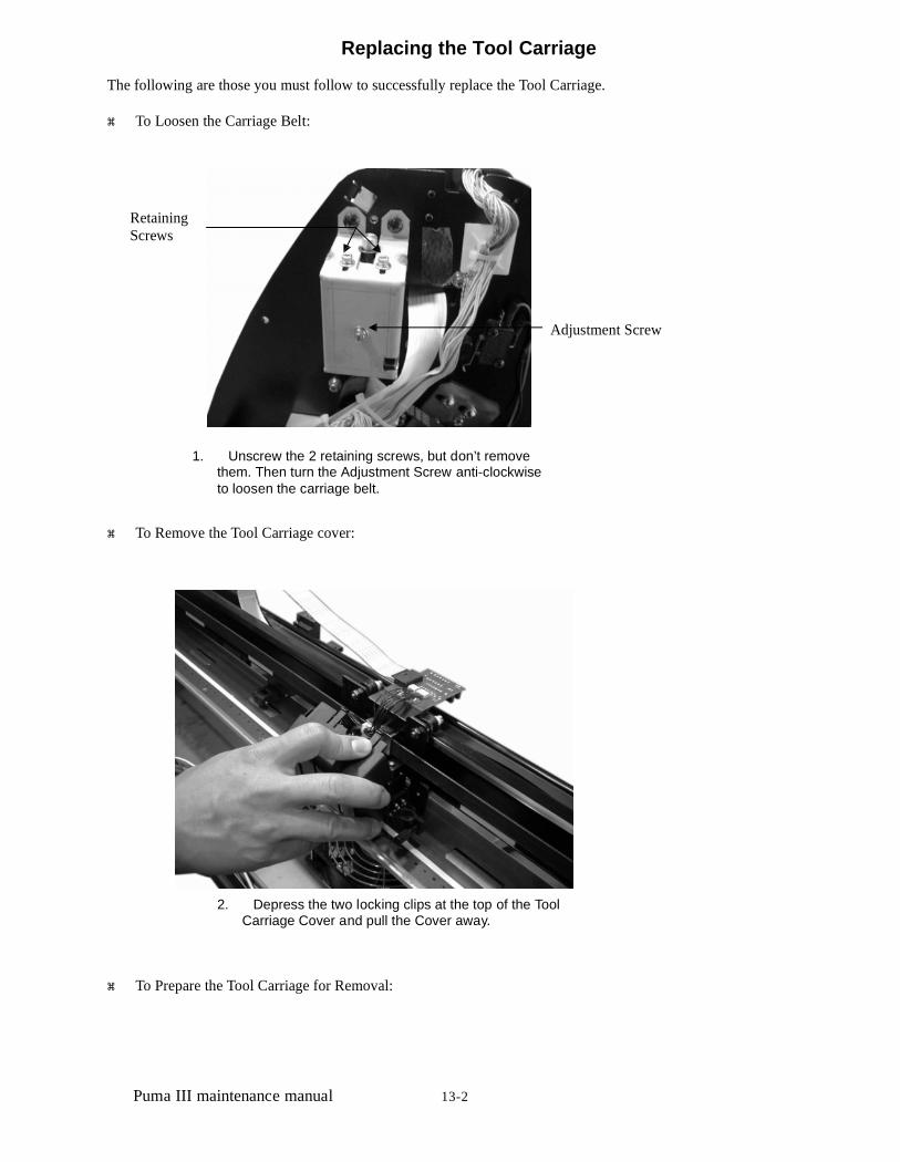
Replacing the Tool Carriage
The following are those you must follow to successfully replace the Tool Carriage.
To Loosen the Carriage Belt:
RetainingScrews
Adjustment Screw
1. Unscrew the 2 retaining screws, but don’t removethem. Then turn the Adjustment Screw anti-clockwiseto loosen the carriage belt.
To Remove the Tool Carriage cover:
2. Depress the two locking clips at the top of the ToolCarriage Cover and pull the Cover away.
To Prepare the Tool Carriage for Removal:

Puma III maintenance manual 14-2
1. Pop up the plastic locking pins using aflathead screwdrIIIer.
2. Disconnect the Flat Sensor Cable.
Bolt A
Bolt B
3. Unbolt and remove nut A and B, and thenunscrew both Bolt A and Bolt B until they areflush with the bracket.

Puma III maintenance manual 15-2
To Remove the Tool Carriage:
1. Separate the Sprung Washer/Rollers asseen in the figure above.
2. Swing the Tool Carriage down and out while keeping theSprung Washer/Rollers apart.
Note 1. To install a new Tool Carriage or replace the original Tool Carriage simply reverse the steps for Tool Carriageremoval.
2. Remember to separate the Sprung Washer/Rollers, and then place them on the Carriage track before youswing the Tool Carriage back into place

Puma III maintenance manual 16-2
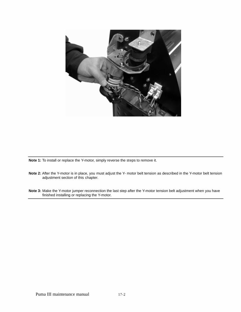
Replacing the Y-Motor
The following steps are those involved in the replacement of the Y-motor:
1. Loosen the all 3 tension-bracket retaining screwsas well as the tension adjustment screw, but donot remove them.
2. Depress the jumper clips, and pull tounplug the 2 Y-motor Jumpers.
3. Lift the belt off of the Y-motor,thenunscrew and remove the 4 Y-motorscrews..
Puma III maintenance manual 17-2
Note 1: To install or replace the Y-motor, simply reverse the steps to remove it.
Note 2: After the Y-motor is in place, you must adjust the Y- motor belt tension as described in the Y-motor belt tensionadjustment section of this chapter.
Note 3: Make the Y-motor jumper reconnection the last step after the Y-motor tension belt adjustment when you havefinished installing or replacing the Y-motor.

Puma III maintenance manual 18-2
Replacing the VCM PC Board
The following is what is involved in replacement of the VCM PC board.
1. Unplug the two sensor connectors, and thenunscrew the two PC board screws to remove theboard.
Note: If the Pinch Roller Sensor is still not effectIIIe after replacement the Tool Carriage or the Flat Cable may needreplacement.

Puma III maintenance manual 19-2
ParallelPortSerialPort
Connector
Connector
USB
Port
Main board Connection or ReplacementMain board connection or replacement must follow the following steps to be sure that no damage comes to eitherservice personnel or the components:
Note: To ensure absolute safety for service personnel and components, please follow the safety instruction at thebeginning of this manual, before installing or replacing any current carrying components
T Parallel Port Connector o unplug the jumpers and connectors from the main board
Y MotorJumper Power Board
Jumpers
Fan Jumpers
Y Motor EncoderJumper
Front PaperSensor Jumper
Flat CableConnector
Control PanelConnector
Lever Limit SwitchJumper
X MotorJumper
X Motor EncoderJumper
Rear PaperSensor Jumper
1. Unplug all of the jumpers and connectors attachedto all off board components.

Puma III maintenance manual 20-2
Note: Please refer to the Puma Wiring Diagram for more detail on jumper and connector attachment
2. Unscrew and remove the 5 restraining screws, andthe pop out support to completely remove the mainboard.
Note: To install or replace the main board simply reverse the steps to remove it.
Replacement of FusesThe Fuse pops out for easy replacement as follows:
Holding clip
Holding clip
1. With your fingers apply equal pressure to both of theholding clips on the Fuse housing, and push it out.

Puma III maintenance manual 21-2
Adjusting the Tool Carriage Transmission BeltWhen you replace the tool carriage or belt itself, the belt tension needs to be adjusted to 150g. This is done as follows:
1. Move the tool carriage tothe far left end of the guidebeam after the toolcarriage or belt beingreplaced. 2. Loosen the 2 retaining screws on top
of the carriage belt roller housing.
3. Use a tension gauge tomeasure the belt’s tensionby placing the gauge’spush arm to the center ofthe belt, as seen in thefigure above.
4. To change belt tensionadjust the belt tension screwon the side of the carriagebelt roller housing.
5. To tighten the tension, turn the belt tens ion screwclockwise. To loosen the tension turn the belt tension screwanticlockwise, until the desired adjustment tension isreached. The desired tension is 150g.
Note: Fasten the retaining screws on the top of the carriage belt roller housing once the adjustment is made

Puma III maintenance manual 22-2
Adjusting the X Motor Tension Belt
1. Loosen the 4retaining screwslocking the X-motorbracket in place.
2. Place the push-pulltension gauge’shook-arm at the holeof X motor bracketand pull the motortoward yourselfalong the directionparallel to the racketedge, and keep it atthe 4kg tensionposition.
3. Tighten the 4 retaining screws to lock thebracket
in place.
4. Fix the tension retaining screw.
Note: The belt connecting the drum and X motor needs to be tightened to a tension of 4 kg.

Puma III maintenance manual 23-2
Adjusting The Y Motor Tension Belt
1. Loosen the 3 retainingscrews locking thetension bracket inplace but do notremove them.
2. Place the push-pull tension gauge’shook-arm at the hole of Y motor bracketand pull the motor toward yourself alongthe direction parallel to the line thatpasses through the motor shaft and thedrIIIe pulley shaft.
3. Once the desired tension is found tightenthe 3 retaining screws to lock the tensionbracket in place.

Puma III maintenance manual 24-2
4. Tighten the tension screw to retain the tension.
Note: The belt connecting the drIIIe pulley and Y motor needs to be tightened up with a tension of 4 kg.

Puma III maintenance manual 25-2

Puma III maintenance manual 26-2
3Troubleshooting
Maintenance DiagnosticsThis section provides maintenance diagnostics as troubleshooting aids. This diagnostic feature is to check hardware to findout which components are good or defectIIIe. Using this diagnostic test facility enables the diagnosing of the hardwarecomponents.
How to Begin Maintenance Diagnostics Diagnostic test for the media sensors Diagnostic test for the width sensor Diagnostic test for the motor encoder and tool holder encoder Diagnostic test for Tool Force (VCM) Diagnostic test for motor movement Diagnostic test for the RS-232 interface Problems and Solutions
To the Contents Page
How to Begin Maintenance Diagnostics
To start the Maintenance Diagnostics facility hold down the On/Off Line button and CUT TEST button while turning on thecutter. The following sub-sections will explain the function of each maintenance diagnostic sequence.
Troubleshooting

Puma III maintenance manual 27-2
SRAM OK
X Mb DRAM OK
System cannot go on testing,LCM display current message
more than 3 seconds
Error occur
Initial State Cancel KeyExit Diagnostic Test
Please Reset Machine
Holder Down?
Down Arrow Key Pressed
Down Arrow Key Pressed
Check Lever Sensor?
Up Arrow Key Pressed Down Arrow Key Pressed
Drum Moves Forward?
Up Arrow Key Pressed Down Arrow Key Pressed
Drum Moves Backward?
Up Arrow Key Pressed Down Arrow Key Pressed
Carriage Goes Left?
Up Arrow Key Pressed
Up Arrow Key Pressed Down Arrow Key Pressed
Carriage Goes Right?
Up Arrow Key Pressed Down Arrow Key Pressed
Check RS-232?
Up Arrow Key Pressed Down Arrow Key Pressed
Check Media Sensors
Up Arrow Key Pressed Down Arrow Key Pressed
Check Width Sensor
Up Arrow Key Pressed Down Arrow Key Pressed
X Motor Encoder?
Up Arrow Key Pressed Down Arrow Key Pressed
Y Motor Encoder?
Up Arrow Key Pressed Down Arrow Key Pressed
Holder Encoder?
Down Arrow Key Pressed
This is a flow chart of the control system tests. Note: X may be 16Mb of DRAM

Puma III maintenance manual 28-2
Diagnostic Test for SRAM and DRAM
This test provides the ability to diagnose the SRAM and DRAM. If these two components are bad, replace them. Otherwisethe cutting plotter will not work properly.
Diagnostic Test for Lever Sensor
This feature diagnoses the lever sensor. If the sensor is faulty, the cutting plotter cannot sense that the pinch rollers havebeen lowered or not. If the lever sensor is down, you will see a lift the lever message on the LCM. If the lever is up, you willsee a lower the lever message on the LCM. You can use the ON/OFF LINE KEY to abort your test when you have finishedthe lever sensor test.
Check Lever Sensor Up/Down
Cancel Key Enter Key
Display leversesor condition messages Previous/Next Test item
Note that: LCM will display one of following messages1.Lower The Lever Please CANCEL2.Lift The Lever Please CANCELThe first message means that the current lever condition is upThe second messsage means the lever is down
Troubleshooting

Puma III maintenance manual 29-2
Diagnostic Test for Media SensorsThis test is to diagnose the media sensors. If they are faulty, the cutting plotter cannot detect the media length correctly. Youcan see the current front and rear sensor condition, you can turn it on or off to see if sensors are out of order or not.
Up/Down Key Check Media Sensors?
Enter Key Pressed Cancel Key
Previous/Next Test item Display CurrentSensor Condition Messages
Change Sensor Condition
Note that: the LCM displays one of following messages1.Now Open Front Eye Cover Rear Eye CANCEL2.Now Cover Front Eye Open Rear Eye CANCEL3.Now Open Front Eye Cover Rear Eye CANCEL4.Now Cover Front Eye Cover Rear Eye CANCEL

Puma III maintenance manual 30-2
Diagnostic Test for Width SensorIf the sensor is faulty, the cutter cannot sense the media width correctly. Refer to the maintenance chapter to replace it. Youmust first move the tool carriage to the rightmost position; the lever must be down to do this. Once this is done please movethe tool carriage to left. Be careful when moving the tool carriage close to the pinch roller, since the message changesquickly when sensor is between on and off.
Check Width Sensor ?
Enter Key
Move CarriageTo
Rightmost
delay 3 seconds
delay 3 seconds
NoLever up or not?
Now Lever is UpLower the lever
Yes
Move Carriage SlowlyTo Left Hard Stop
Pinch Roller SensorNo Yes
on or not?
Now Sensor is offMove Carriage Slowly
Now Sensor is OnMove Carriage Slowly
Diagnostic Test for Motor Encoder and Tool Holder Encoder
Troubleshooting

Puma III maintenance manual 31-2
This feature provides the ability to diagnose the X and Y motor encoder and tool holder encoder. If the encoder is defectIIIe,the cutting plotter cannot work properly. To check if the encoder is bad or good, you can apply a slight force to the tested part(such as a drum, the tool carriage or the tool holder) then examine the readings. If the encoder reading changes dramatically,the encoder is bad. Refer to the maintenance chapter to replace the motor or tool carriage.
X M oto r E n code r ? U p/D own K ey
E nter K ey
C anc el_keyM ove D rum B y H andWa it fo r 3 second s P reviou s/N e xt tes t ite m
D isp lay enc oder count
X M oto r E nco derR ead in g C A N C E L
X Motor Encoder Test
Y Motor Encoder ? Up/Down Key
Enter Key
Cancel_key
Move Carriage By HandWait for 3 seconds Previous/Next test item
Display encoder count
Y Motor EncoderReading CANCEL
Y Motor Encoder Test

Puma III maintenance manual 32-2
Holder Encoder ? Up/Down Key
Enter Key
Cancel_keyMove Holder Up/Down
W ait for 3 seconds Previous/Next test item
Display encoder count
Holder Motor EncoderReading xxx CANCEL
Diagnostic Test for Tool Force (VCM)
This test is to diagnose the VCM. If the VCM is bad, the tool carriage cannot perform the up/down action that generates thetools force on the material.
Note: VCM means Voice Coil Motor that generates tool force
Diagnostic Test for Motor Movement
This feature is to diagnose the X and Y motors and drIIIers. If you encounter a motor movement problem, try to change themain board first. If the problem still remains after replacing the main board, try replacing the motor.
Drum Moves Forward ? Up/Down Key
Cancel Key Enter Key
X Motor Moving NowForward CANCEL
Previous/Next test item
Troubleshooting

Puma III maintenance manual 33-2
Drum Moves Backward ? Up/Down Key
Cancel Key Enter Key
X Motor Moving NowBackward CANCEL Previous/Next test item
Carriage Goes Left ? Up/Down Key
Cancel Key Enter Key
Y Motor Moving NowForward CANCEL Previous/Next test item
Carriage Goes Right ? Up/Down Key
Cancel Key Enter Key
Y Motor Moving NowBackward CANCEL Previous/Next test item
Note: The X motor controls the Drum. The Y motor controls the Carriage.
Diagnostic Test for the RS-232 Interface

Puma III maintenance manual 34-2
This feature provides the ability to diagnose RS-232 interface, and checks communication between the cutter and computer.
Check RS-232 ? Up/Down Key
Enter Key Previous/Initial state
Cancel Key
Type any characters FromComputer CANCEL
No => Type any characterfromthe computer Error or not? Yes Wait for 3 seconds
The message you typed Error Messages
Type character againY:ENTERCANCEL
Type any characterfromcomputer

Puma III maintenance manual 35-2
Note that: Do not press keys too quickly, or it may cause an overrun error
Problems and Solutions
This section discusses typical problems you may encounter while operating the cutting plotter and offers you possiblesolutions
The line quality is not good enough at the corner or the end point.Causation and recovery:Forgetting to fasten the tool (Fasten it.)The blade is worn. (Change it.)The offset value is wrong. (Correct the offset value.)Media is not flat enough. (Reload the media.)Media is wet. (Change it.)The quality of media is not good enough. (Change the media.)Drum or pinch roller is worn. (Change the drum set or pinch roller.)
The position of pinch roller cannot be detected so that the media width cannot be determined correctly.Troubleshooting Causation and recovery:Forgetting to lower the pinch roller. (Enable the pinch roller and push the lever forward to lower down the pinch roller) Theorientation of the width sensor on the carriage PCB is not correct. (Adjust the orientation of the carriage PCB)The position of the width sensor on the carriage PCB is too high to sense the block bar on the pinch roller. (Lower thecarriage PCB)Flat cable is broken. (Change it.)Width sensor is damaged. (Change it.)Carriage PCB set is damaged. (Change carriage set.)
The function of “Set New Origin” does not work.Causation and recovery:The origin point will be set by pressing the ENTER button when the Puma is in an OFFLINE state, only then will the LCDdisplay the distance between the new and old origin.
Media shifts away when plotting a long drawing.Causation and recovery:The media is not accurately aligned. (Reload the media.)Pre-run the media back and forth using the arrow key will help. (Reload the media and pre-run.)The edge of the media is not straight. (Change the media.)Media is too thin. (Change it.)Drum is coated with paper chips or dust. (Clean the surface of drum.)Drum or pinch roller is worn. (Change the drum set or pinch roller.)
The lines quality is wavy.Causation and recovery:Forget to fasten the tool fastening screw. (Fasten it.)The blade is worn. (Change it.)The acceleration is too high. (Set the acceleration to a lower value; please refer to the default value.)The carriage belt tension is incorrect. (Adjust the belt tension.)X or Y motor belt tension is incorrect. (Adjust the belt tension.)The spring loading bearing of carriage is damaged. (Change the carriage set.)The length of the media is too short in X direction. (Change the media.)Media is too thin. (Change it.)

Puma III maintenance manual 36-2
Drum or pinch roller is worn. (Change the drum set or pinch roller.)X or Y motor is damaged. (Change it.)
Data loses when plotting.Causation and recovery:Memory chip is bad. (Change it.)Main board set is bad. (Change it.)
Fatal error occurs when loading media.Causation and recovery:Forget to pull out some media from the media roll. (Pull out some media from the roll before you start to load media.)X motor belt is too tight. (Adjust the belt tension.)
Feel electrostatic discharge.Causation and recovery:Power out let does not have ground connection. (Improve it.)
Carriage locked, cannot move.Causation and recovery:The spring loading bearing of carriage is damaged. (Change the carriage set.)The carriage belt is too tight. (Adjust the belt tension.)Some fasten screws are loose so that the shaft bearing of carriage belt drops.(Fasten the screws.)
The keyboard does not work.Causation and recovery:The connection between keyboard and main board is broken. (Re-plug the connector or change the keyboard set.)

Puma III maintenance manual 37-2
Dust or moist surface makes a bad keyboard contact. (Change the keyboard set.)
The machine makes noise when it is on the standby status. Causation andrecovery:The screws of tool carriage cover are loose. (Fasten the screws.) X or Y motor beltis loose. (Adjust the belt tension.)The carriage belt is loose (Adjust the carriage belt tension)The drIIIer board set is damaged. (Change it.)
The machine makes abnormal noise from the drum set when it is running. Causation andrecovery:X or Y motor belt is loose. (Adjust the belt tension.) The drIIIer boardset is damaged. (Change it.)The gear at the left of drum set is not tightly mounted on the shaft. (Change it.) The screws thatfasten the drum to the shaft are loose. (Fasten the screws.)X or Y motor is damaged. (Change it.)
The tool carriage does not perform the up/down action. Causation andrecovery:The blade holder is not installed properly. (Re-install it, please refer to user’s guide.) The flat cable isbroken. (Change it.)The carriage PCB is damaged. (Change it.) VCM is damaged.(Change the Carriage set.)The encoder of the VCM is damaged. (Change the Carriage set.)The drIIIer board set is damaged. (Change it.)The linear bearing shaft of VCM is rusty. (Change the Carriage set.)The two small bearings clamp the linear bearing shaft too tight. (Adjust them).
There are some unexpected lines on the final plot. Causation andrecoveryThe blade holder is not installed properly. (Re-install it; please refer to user’s guide.)The media is not flat enough. Maybe there are some bubbles on the surface. (Re-load the media) The fan cannotmake enough airflow to suck the media. (Change the fan or drIIIer board)The carriage does not perform the up action. (Please refer to the previous paragraph)The command of output file of cutting software package is not compatible with HPGL or HPGL/2. (Ask your cutting software packageagent for help.)There are some communication errors. (Check the communication protocol.)
There appears an unexpected tool force. Causation andrecovery:The setting of tool force is wrong. (Reset the tool force.)The blade length out of the blade holder is too short. (Re-load the blade.)The initial force setting is wrong. (Reset the initial force. please contact the manufacturer.) VCM is damaged.(Change the carriage set.)VCM encoder is damaged. (Change the carriage set.)
Media drops sometimes. Causation and torecovery:Media is loaded askew. (Re-load the media.)The position of pinch roller is not on the top of drum. (Move the pinch roller to a right position.) The edge of mediais broken. (Change the media.)The front of media is not even. (Cut the front edge of the media evenly and reload the media.) Drum is coatedwith paper chips or dust. (Clean the surface of drum.)Drum or pinch roller is worn. (Change the drum set or pinch roller.)
Troubleshooting

Puma III maintenance manual 38-2
Appendix
Puma Parts and Accessory List Spare Parts Customer Service Request Form
To the Contents Page
Appendix

Puma III maintenance manual 39-2
T
Spare Parts Reordering Form
星雲電腦股份有限公司he Electro-Optical Automation company
Customer Service Request FormPart RequestRMA Request RMA# Date:
Company Name:Contact Person: Phone: Fax:
Address:Product Name: Model Number: Serial Number: Date of purchase:
Part No: Part Name.: Qty Payment U/Price Ship date
F.O.B F.O.C SAS US$195.00
F.O.B F.O.C SAS
F.O.B F.O.C SAS
F.O.B F.O.C SAS
F.O.B F.O.C SAS
F.O.B F.O.C SAS
F.O.B F.O.C SAS
F.O.B F.O.C SAS
F.O.B F.O.C SAS
F.O.B F.O.C SAS
Problem Description:
Correct Action Taken & Current Condition:
Comment:(below filled out by G.C.C)Shipping way: EMS DHL UPS FEDEX With Sales Order Others:
Freight Charge : Collect Prepaid Others:
●Please sign back to confirm your service request.