pulsed inductive macron propulsion david … a. distribution unlimited. pulsed inductive macron...
TRANSCRIPT
Distribution A. Distribution Unlimited.
PULSED INDUCTIVE MACRON PROPULSION David Kirtley and John Slough
MSNW LLC, Redmond, WA 98052, USA and
Jacob Schonig and Andrew Ketsdever University of Colorado at Colorado Springs, Colorado Springs, CO, 80918 USA
ABSTRACT
Recent advances in energy storage and solid-state switching enable the use of
peristaltic, pulsed inductive acceleration of non-ferritic particles for space propulsion. Macron
Launched Propulsion (MLP) electromagnetically accelerates gram-sized aluminum cylinders
(macrons) to 8 km/s. A series of pulsed electromagnetic coils sequentially fire and accelerate a
macron efficiently and accurately through induced currents. The macrons are accelerated in sub-
kJ stages using exclusively solid-state devices. As a result, efficient power processing and energy
recovery become possible. As a consequence of having no mechanical or electrical contacts,
long life and fast repetition rates can be achieved.
The mission benefits of a macron-acceleration based propulsion system are far reaching.
First, with no ionization losses, a highly-efficient thruster, modeling suggests upwards of 90%
operating at 600-1000 seconds specific impulse, would allow very rapid response orbital plane
and altitude changes. This technology is uniquely suited to providing primary, in-space propulsion
and is applicable for 10+ kW-level propulsion systems. This would enable multi-day orbital
maneuvers, rather than the traditional multi-month EP missions. This also implies high thrust-to-
power of greater than 200 mN/kW at 800 seconds Isp. This technology can successfully bridge
the performance gap between bi-propellant thrusters and conventional electric propulsion. The
traditional benefits of a pulsed system also apply: exceptional variability in thrust and power
levels, variable specific impulse, and high specific power (kW/kg). The inert solid propellant is
easily and compactly stored, and interaction with the spacecraft is minimal. In LEO, research
proves all macrons fired with velocity components predominately in either the positive or negative
spacecraft velocity vector (RAM) direction will either escape or reenter, respectively. Whereas in
GEO, all macrons fired with and exit velocity greater than 8 km/s will escape Earth’s gravitational
field regardless of firing angle.
Presented is an introduction to the Macron Launched Propulsion concept, including a
theoretical and experimental program to demonstrate a rep-rated, high-efficiency MLP system.
Accelerator modeling, macron trajectory, and systems-level design criteria will be given.
Additionally, initial results from testing of a multi-stage MLP accelerator will be detailed.
INTRODUCTION
The attempt to electromagnetically accelerate solid masses to high velocity is almost as old as the discovery of electromagnetism itself, dating as far back as the end of the 19
th century. In
this long history, the motivations for the development of these electromagnetic (EM) accelerators were many – from meteor simulation to impact fusion. Some of the more prominent approaches are well known such as the rail gun, coil gun, mass driver, and Maglev accelerator. By large measure, the focus of these efforts was primarily for the purpose of accelerating payload to orbital speeds (~ 7 km/s), and not to directly provide for the production of spacecraft thrust. There were of course a handful of concepts and experiments that looked at the utility of an EM accelerator for this purpose. Given the propellant velocity desired for space propulsion (Isp > 1000 s), the mass to be accelerated must be on the order of a gram to keep the required energy storage reasonable. If such an EM propulsion system can be achieved, the advantages are clear. Efficiencies can approach unity at any Isp, the solid propellant is easily stored, and interaction with the spacecraft is minimal. The same device used for propulsion could also be used for space-based directed energy applications as well. It is believed that the most promising approach to the acceleration of the macro-particle, or “macron”, and the one to be examined in the proposed study is the use of a pulsed inductive accelerator for macron launched propulsion (MLP).
Pulsed induction is an acceleration mechanism based on the repulsive force exerted on a conductor that is magnetically induced by employing a series of one or more pulse coils. Because this process is inductive no direct mechanical or electrical connection with the projectile is required. In its simplest manifestation, the physics is similar to that employed in the plasma-based pulsed inductive thruster (PIT) and is closely related to the Magnetically Accelerated Plasmoid (MAP) thruster, developed at MSNW with funding from AFRL [1]. In this device, the acceleration of milligram plasmoids attained velocities of 200 km/s. The macron accelerator envisioned here would operate at much slower speeds and on a much smaller physical scale. This greatly simplifies the acceleration technology, and provides for a thruster that maximizes thrust for a given power rather than Isp. Intense macron acceleration with a single pulse coil geometry similar to the PIT has been demonstrated in the past. In these experiments, a 2 gram aluminum washer was accelerated up to 5 km/s [2]. Given the breakthroughs in solid state switching and magnetic pulse compression since these results, a good case can be made that propulsion based on the EM acceleration of macrons should be reevaluated. The maximum velocity that can be achieved with this approach is independent of the magnetic waveform, and is primarily the consequence of the heating and ultimate vaporization of the macron from the induced currents. The ultimate velocity is thus determined by the intrinsic behavior of the material conductivity, its density, the induced current sheet thickness, and number of stages. Macron Launched Propulsion seeks to develop a pulsed inductive accelerator that can accelerate gram scale macrons to a velocity of up to 10 km/s, and can operate at a rep rate of up to 10 Hz. The first step is to develop and demonstrate a multi-stage launcher to demonstrate the efficient acceleration of macro-particles.

Distribution A. Distribution Unlimited.
MOTIVATION
There is a distinct lack of propulsion systems capable of 600-1000 seconds of specific impulse. Thruster systems that rely on gas heating and expansion (combustion, electrothermal) are fundamentally limited by frozen flow and material thermal properties to low specific impulses. In fact, with the exception of hydrogen (which has very unfavorable tankage requirements), electrothermal propulsion systems are limited by maximum temperatures of 3000 K, which translates into a maximum of 300 seconds Isp (for He and Ammonia). For electrostatic and magnetic propulsion systems the key parameter is ionization/plasma formation energy. The kinetic energy of a particle must be greater than the ionization energy. For typical plasma formation energies of 150+ eV/ion this amounts to 1600 seconds with heavy Xenon particles and much higher for lighter molecular weights. Therefore existing propulsion systems are limited to a range given by Equation 1, where Cp is specific heat, T is gas temperature, eion is plasma formation loss, Mo is the ion mass. With few exceptions, all current work in advanced electrothermal and electrostatic propulsion is driven by the desire to maximize operating temperatures and minimize plasma formation losses, respectively, for a given operational regime.
o
ionep
M
euTC
22
(1)
Clearly a macron propulsion system would not be subject to the same specific impulse limitations as traditional EP devices. In fact, it would optimize for the 600-1000 second specific impulse gap. Additionally, unlike liquid droplet acceleration, the MLP would have very high thrust and power densities.
The mission benefits from a macron-acceleration based propulsion system are far reaching. First, with no ionization losses, a highly-efficient thruster (modeling suggests upwards of 90%) operating at 600-1000 seconds would enable very rapid-response orbital plane and altitude changes. This would enable multi-day orbital maneuvers, but with the thrust efficiency of an efficient electric propulsion (EP) multi-month orbital insertion. This also directly translates to high thrust-to-power (T/P) of > 200 mN/kW at 800 seconds Isp. The traditional benefits of a pulsed system also apply: huge variability in thrust and power levels, variable specific impulse, and high specific power (kg/kW). And while the specific impulse may not minimize mass, both cost and situational response times can be optimized depending on critical mission parameters.
And while the propulsive aspects themselves warrant research in this area, Air-Force specific benefits are even more attractive. Besides the rapid-response capabilities outlined above, a macron-based propulsion system would also have no plume or operational signature for identification and tracking. It would be ideal for Space Situational Awareness missions involving close inspection and tracking. Finally, the MLP will be able to rapidly (>1 Hz) eject solid bodies at greater than 6 km/s. The ability to project gram-size macrons with kJ-level energies would be a radical departure from current satellite defensive capabilities. It would be capable of rapidly and effectively responding to threats. The MLP would have a sphere of influence limited only by orbital mechanics of the ejected particles.
NASA supported missions also have significant benefits. Specific impulses in the range of 800-1000 seconds are highly desirable for high-power missions where transit times are critical, such as manned missions. Additionally, solid aluminum propellant has a high packing mass fraction, low tankage mass, and infinite lifetime. Finally, for lunar, asteroid, and deep space missions, propellant can be stored, mined, or pre-positioned for revolutionary decreases in total propulsion system mass.

THE MACRON LAUNCHER
It is clear from the considerations above; the launcher must be simple, reliable and robust. It is believed that the prototype design to be tested possesses all these features. There is a wide array of possible methods to achieve the desired velocities and masses. The velocity requirement is rather modest compared to that attained by a large range of projectile acceleration methods. There are both electromagnetic (EM) and gas dynamic approaches that have achieved velocities in the range of interest. Two-stage light gas guns have accelerated 1 g aluminum spheres to velocities of 8 km/s [3]. Rail guns have achieved similar velocities with much larger masses [4]. Pulsed inductive coils [2] and coil guns [5] are also possible devices. It turns out that however none of these devices can meet all the attributes desired for the launcher. For instance, the light gas gun requires large and fairly complicated firing arrangement, and typically employs chemical explosives as a first stage. It would thus be unlikely that an array of such devices, given the compounding difficulty with light gas storage, could achieve sufficiently low power to mass ratios (~ 1 kg/kW) desired for space propulsion. In addition, the significant interaction of the projectile with the gun barrel would severely limit repetitive operation if not prohibit it altogether. With electromagnetic (EM) launch techniques these issues can be significantly ameliorated, therefore only EM techniques will be considered.
Rail guns have been pursued for many years for goals as diverse as directed energy weapons to space launch. There are two significant problems for the rail gun. It has poor energy coupling efficiency, and the arc nature of the current commutation makes long term repetitive pulsing very difficult. Purely inductive coupling eliminates most of the drawbacks of the rail gun. The coil gun employs a ferromagnetic projectile and can theoretically achieve velocities of up to 2 km/s. Core saturation and heating are the limiting factors that prevent application to propulsion at the higher Isp desired here. The requirement that the macron be ferromagnetic is also very constrictive.
As was mentioned, it is actually possible to achieve very high velocities from a single pulsed inductive coil (see Fig. 3). The force is derived from Lens’ law with an equation of motion that
depends on the coil-projectile geometry and currents:
dz
dM)t(I)t(I)t,z(F
cp
pc (2)
where Mcp is the mutual coupling between coil and projectile. The large velocities (~5 km/s) obtained for the 2 g aluminum washer with a coil driver arrangement as depicted in Fig. 1 however came at a price. The problem with a single stage launch to high velocity is the required concentration of power in time and space. This requires significant voltages and current densities in the launch coil. During launch the pulse coil undergoes tremendous forces where joule heating and fatigue would be major concerns for repetitive operation. For more modest launch velocities (~ 500 m/s) repetitive operation is much more manageable, and has been achieved [6]. While this is not a sufficient terminal velocity for this application, such a technique could be highly useful in
dt
)IM(d
dt
dI)LL(IRV
pcpccdpcc
dt
)IM(d
dt
dIRI0
ccpp
pp
dt
)IM(d
dt
dI)LL(IRV
pcpccdpcc
dt
)IM(d
dt
dIRI0
ccpp
pp
Figure 1. Pancake coil inductive launcher. Equation of motion (Eq. 2) together with the circuit equations above determine macron motion.

Distribution A. Distribution Unlimited.
initiating the macron acceleration process. What is clearly required is the staged inductive acceleration of the macron. In this manner the kinetic energy can be added incrementally avoiding the power concentration issues. The MLP’s pulsed inductive acceleration technique (see Fig. 2) is very similar to that employed in the FRC acceleration and merging experiments at MSNW on the Inductive Plasma Accelerator (IPA) [7]. In this case the terminal FRC velocity can exceed 400 km/s. Here the two identical FRCs must arrive at the experimental midplane within a fraction of a microsecond. Even this extreme case of merging has been achieved resulting in a stable, hot long-lived FRC. The technological challenge presented by macron launch should be far less demanding.
MACRON ACCELERATION THEORY
Many circuit-law based techniques are available for understanding and optimizing a pulsed-inductive launcher of this type [8,9], however the ability to launch purely cylindrical objects allows for a unique simplification of coupling theory. If the macron is sufficiently thick that it acts as a complete flux-excluding shell and the Ohmic losses in the macron and the discharge coil (discussed in detail later) are minimized, a simplified inductive-energy argument can be used to maximize kinetic energy.
Consider the case where an axial magnetic field is introduced into a flux conserving coil (see Fig. 3). The flux (and thus energy) is held constant as the conducting body drifts to the coil edge and is accelerated out of the cylinder by the gradient field there. The final state has the coil empty with a vacuum magnetic field Bvac, and the projectile of mass Mp moving away at a velocity vz, and kinetic energy Ek = ½ Mpvz
2. No energy is added to the
system as the projectile is ejected so applying energy conservation from the state before to after ejection results in:
2
zppp
0
2
vacppc
0
2
ext vM2
1LA
2
BL)AA(
2
B
(3)
From flux conservation:
cvacpcext AB)AA(B (4)
Figure 2. Pulsed inductive acceleration of a macron. Subscript ‘k’ denotes individual coil coupling and current properties.
Bvac
Bvac
Bext
Bvac
Bvac
Bext
Figure 3. Ejection of a conducting body from a flux conserving coil.

where Ac and Ap are the cross sectional area of the coil and projectile respectively. Equations 3 and (4) together determine the kinetic energy gained by the projectile in terms of the vacuum magnetic energy:
2
2
BVKx1
xzEE where
c
p
c
p
r
rx,
L
Lz (5)
It can be seen that the projectile energy is only a function of the vacuum field and projectile/coil geometry. Not surprisingly, the closer the projectile radius is to the coil radius the better the energy coupling. This dependency is shown graphically in Fig. 4. For a centimeter scale coil, a reasonable maximum value for x is ~ 0.9. For a projectile to coil length ratio of 0.7, the achievable projectile kinetic energy would be nearly three times the vacuum field energy. This may seem odd, but it merely reflects the fact that the projectile has a profound influence on the circuit as it enters and then exits the coil. On entering the projectile significantly reduces the coil volume. The external circuit momentarily sees a much lower coil inductance and the circuit current (and thus magnetic field) increases considerably. This provides for a much larger magnetic force to act on the projectile as it exits. Another way of thinking of it is that flux conservation requires that the magnetic field, Bext, between the coil and projectile to significantly increase. Flux exclusion from the projectile induces a large current in the coil and equally large counter current in the projectile providing for a large repulsive force. Very preliminary experimental testing has demonstrated a value for x of 0.72 and a vacuum field amplification of 2.4.
TRANSIENT COIL THEORY
The standard operation of the solid state drivers is to produce a full sinusoid period as the capacitor first discharges into the coil followed by current reversal and a recharging of the capacitor at which point the circuit is opened. The full cycle returns all unused inductive and capacitive energy to the capacitor for the next pulse. With this type of operation, the only loss is the energy transferred to the projectile and a much smaller Ohmic loss to the circuit. It is the ability of the macron launcher to be operated in this manner that provides for the potential to achieve an extremely efficient propulsion device.
0.6 0.7 0.8 0.9 1
4
3
2
1
0
2
2
x1
xz
1z
7.0z
5.0z
Coil winding
region
Projectile radius
x0.6 0.7 0.8 0.9 1
4
3
2
1
0
2
2
x1
xz
1z
7.0z
5.0z
Coil winding
region
Projectile radius
x
Figure 4. Dependence of energy coupling on coil-projectile radius and length ratios. See Eq. (7).
Figure 5. Acceleration methodology with reversed coil operation. Each coil is pulsed for full cycle, sequenced for maximum field gradient across projectile.

Distribution A. Distribution Unlimited.
In order to utilize the inductive energy in the MLP a unique coil orientation is used. Each coil is operated in an alternating direction allowing for maximum acceleration and coupling, while minimizing flux soak-through. Figure 5 shows the acceleration of the macron through the first full cycle and the operation of a following coil during the reversed cycle. The following coil acts then to amplify the second half-cycle field as well as minimizing the penetration of the skin currents in the macron, preventing soak-through and tilt-instability issues. As magnetic force depends only
on pc II , directionality is unimportant for acceleration.
MACRON COMPOSITION
The small scale of the projectile makes possible the high exit velocity at reasonable energy storage (~25 kJ) and power (25-250 kW) does carry with it certain implications. For most applications, vaporization of the macron during acceleration should be avoided. It was first pointed out by Cnare in his landmark foil implosion experiments [10] that this process can limit the ultimate macron velocity (energy) that can be attained. The material properties relating to this heating (electrical conductivity, melting point, heat capacity, etc.) can be characterized by the action constant gmat defined by the “current integral”:
2
mat
t
0
2 AgdtIm
(6)
where I is the magnitude of the induced current flowing through the macron cross-sectional area, A, in the direction of current flow. Normalizing to the action constant gAl for the vaporization of aluminum from 300 °K one has for the maximum velocity:
M
Al
10
m g10x8.6v
, (7)
where M is the macron material density and is the wall thickness. While this is not a significant limit for gram scale macrons, it can limit the velocity that can be imparted to smaller mass (thinner
wall or ) macrons. The maximum velocity for various materials for a given wall thickness is given in Fig. 6. aluminum was chosen as the material of choice due to its excellent operating parameters and low cost.
0.347.95E+060.222.20E+16Mg
0.013.21E+050.065.79E+15Pb
0.337.70E+060.121.19E+16Na
0.681.61E+070.131.36E+16Li
0.691.64E+072.302.33E+17Cu
1.333.15E+070.919.24E+16Be
0.194.53E+061.371.39E+17Au
1.052.49E+071.051.07E+17
Al
(6061)
1.002.37E+071.001.01E+17Al
0.399.19E+061.511.53E+17Ag
Element Current Intgrl. Ratio to Al vmax/ (m/s) Ratio to Al
Figure 6. Candidate macron materials

OPERATIONAL THRUSTER DESIGN AND CONFIGURATION
Using state of the art capacitor, pulsed magnet, and solid state switching technology it is believed that a thruster of high efficiency can be designed and built with an Isp range of 100-1000 seconds specific impulse. Therefore, using standard scaling laws and modern pulsed power techniques an operational thruster design can be calculated. Two sample thrusters are shown, a 50 kW and a 300 kW thruster at 800 s Isp. Operational performance and mass scaling parameters are shown in Figure 7. Intriguingly, the primary efficiency loss in the MLP thruster is in Ohmic heating of the macron itself. Therefore, as the macrons are ejected from the thruster without significant heat transfer to the thruster walls, little thermal management of the thruster body is required.
ORBITAL MECHANICS OF THE MACRON PLUME
One of the key parameters in the operation of Macron Propulsion is the trajectory of the macrons themselves. The overall goal of the orbital analysis was to determine the effects these macrons will have on the debris environment, their potential hazards to other orbiting spacecraft, and formulation of possible applications for this technology. Stray or unaccounted for macrons orbiting the Earth with high velocities are highly undesirable and may impact space operations. In order to understand and in turn minimize the adverse affects of these macrons, simulations were created, through the use of Satellite Tool Kit (STK), to model their behavior in space once the macrons have been fired. The two primary parameters which ultimately determine the final trajectory of these macrons are the directions and velocities at which the macrons are fired. Therefore, comprehensive models were created to simulate all firing angles (0-360 degrees) with exit velocities between 5-10 km/s.
The overarching simulation concept was designed to predict the orbit of a macron being fired
from a circularly orbiting satellite at zero inclination from various altitudes. For ease of simulation, macrons were modeled as solid, aluminum spheres with a mass of 1g. Three primary firing altitudes were established: 300 km, 20,000 km and 35,780 km (LEO, MEO, and GEO, respectively). At these altitudes, individual simulations were created for all firing angles across a two-dimensional plane parallel to the local horizon of Earth with the principle coordinate system based off of the velocity vector (RAM). In terms of spacecraft maneuvering, it is inefficient to
Macron Mass 1 gram Al
Coupling Parameter 2.5
Macron Velocity 8 km/s
Macron Kinetic Energy 32 kJ
Per Pulse Energy 60 kJ
Repetition Rate @ 100 kW 2.5 Hz
Repetition Rate @ 400 kW 10 Hz
Total Thruster Length 2 m
Capacitor Storage Mass 120 kg
PPU Mass (switching, electronics) 85 kg
Structural/Cooling Mass 40 kg
Specific Power @ 100 kW 0.4 kW/kg
Specific Power @ 400 kW 1.6 kW/kg
T/P @ 800 s Isp ~200 mN/kW
Figure 7. Macron Thruster Parameters

Distribution A. Distribution Unlimited.
thrust outside of this plane; therefore, firing angles outside of this plane were not simulated (See Fig. 8).
Figure 8. 2-Dimensional macron firing plane parallel to the local horizon of Earth (x-y plane)
Preliminary results from the orbital trajectory simulations made it apparent that third-body effects, on a given macron trajectory, were substantial. At very specific and prescribed firing angle and exit velocity combinations, macrons have the potential to enter into highly elliptical orbits with semi-major axes approximately equal to or greater than three-fourths that of the Moon. These very unique orbits are referred to as triple point orbits. A triple point orbit is an orbit in which the Moon’s gravitational interactions with an orbiting macron are sufficiently intense to effectively alter a previously orbital trajectory into an escape, reentry or a new triple point orbital trajectory. Over time, simulations have shown the majority of these triple point orbits will ultimately enter into an escape or reentry trajectory. This is due to the reality that triple point orbits enter into a cycle of constant Moon-macron interaction which can only be terminated with a given Moon-macron interaction resulting in an escape or reentry trajectory. However, simulations have shown it is possible for a triple point orbit to be altered into another long-lived Earth orbit. These situations are extremely rare and are therefore neglected within the data. Furthermore, triple point orbital effects are most notable at lower macron exit velocities (5-9 km/s) and are minimal at higher macron exit velocities (10+ km/s).
Likewise, all escape trajectories have an inherent potential to interact with the Moon’s gravitational field which has the potential to drastically alter a macron’s trajectory. Therefore, the relative positioning of the Moon at the time a macron is fired was determined to be significant. All simulations were conducted using a standardized Epoch time to ensure constant relative positioning of the Moon at the time of firing. Firing velocities were varied between 5-10 km/s for all possible firing angles and initial altitude combinations. The resulting trajectories (escape, reenter or orbit) were established and recorded for all possibilities. See Fig. 9. GEO data is not shown due to the fact at 5 km/s exit velocity, only angles between 120-240 degrees orbit while all other firing angles escape. Exit velocities greater than 8 km/s regardless of firing angle, result in an escape trajectory.

LEO MEO
Figure 9. Macron trajectory as a function of firing angle. (Zero degrees points in the RAM direction)
--Escape
--Orbit
--Reenter
--Triple Point

Distribution A. Distribution Unlimited.
With the exception of a few scenarios in LEO, all macrons fired with any component of their velocity in the positive RAM direction escaped. Furthermore, in LEO, all macrons fired solely in the negative RAM direction (the most efficient direction to thrust in order to increase the semi-major axis of an orbit) will be place on a reentry trajectory. In general, a spacecraft orbiting in LEO will have a velocity approximately equal to 7.8 km/s; therefore, if a macron is fired in the negative RAM direction with an exit velocity of 8 km/s, the macron’s effective velocity with respect to Earth will be approximately 0 km/s, after firing. This will literally cause the macron to fall straight back to Earth. This reality will become extremely significant when analyzing possible applications of this spacecraft propulsion system because this situation minimizes the level of impact to the overall space environment.
The next topic of analysis, for all firing angle and velocity combinations which resulted in orbital trajectories, became the determination of orbital lifetimes. Two orbital lifetime models were created through MATLAB; one code was designed to integrate the force due to atmospheric drag throughout a prescribe orbit while the other code took a more hierarchical approach based off of the Equations of Variation. In both codes, no third-body or perturbational forces were taken into account. The only external force accounted for was the force due to atmospheric drag. For simplicity, atmospheric drag was considered to be negligible and hence disregarded at orbital altitudes greater than 1,500 km. Atmospheric density data was obtained through the Naval Research Laboratory’s Mass Spectrometer and Incoherent Scatter Radar model derived from empirical data released in the year 2000 (NRLMSIS-00) [11] for solar minimum, maximum and mean. This data was then incorporated into both drag models with an 11 year solar cycle in order to produce higher levels of accuracy. Each MATLAB code was designed to terminate once the macron’s altitude of perigee degraded below 200 km or once the orbital lifetime calculation reached 1,000 years. All orbital lifetimes greater than 1,000 years were considered to be “permanent” orbits. Both MATLAB codes produces similar results; however, computational times varied drastically. The MATLAB code which calculated orbital lifetimes based off of an integration of the force of drag was not practical to run due to computation durations of several weeks per orbital lifetime calculation. Therefore, the MATLAB code which utilized the Equations of Variation was adopted and applied to all subsequent MATLAB orbital lifetime calculations.
STK also provides a capability to determine the orbital lifetime for all macrons with orbital trajectories. Both STK and the developed atmospheric drag model were used to assess orbital lifetimes and compare with each other. Orbital lifetimes were calculated for macrons being fired from a circular orbit with altitudes varying from 300 to 600 km at an interval of 100 km. STK orbital lifetimes were calculated within a three-body system using NRLMSIS-00, rotating atmosphere assumptions, J2 perturbations and solar pressure forces. Likewise, calculations were terminated once any given orbit resulted in an orbital lifetime greater than 1,000 years. The purpose of these simulations was not only to determine how long orbiting macrons fired at a given angle with a given exit velocity will stay in orbit but also to determine if any firing angle and exit velocity combinations had less impact on the space environment than other combinations. Imbedded within this data is an intrinsic amount of error due to inaccuracy in predicting space weather [12]. A random collection of orbital trajectories was compiled to conduct a comparison analysis between the orbital lifetimes calculated by the MATLAB code and STK. This overall collection of trajectories encompassed all firing angles, velocities and altitudes, collectively. In general, orbital lifetimes calculated through the developed MATLAB code, which only took into account the force due to atmospheric drag, were within the same order of magnitude as those orbital lifetimes calculated by STK, which took into account all real world forces. Therefore, both methods of orbital lifetime calculation were concluded to be reasonably accurate. However, due to easy of computation, STK orbital lifetime calculation techniques were adopted and applied to all macron orbital trajectories. Figure 10 displays the results for all orbital lifetime results.

In terms of drag calculations (see Eq. 8), there are four primary factors which influence the
force of drag on a given object orbiting the Earth. One is an environmental variable (atmospheric
density, ) and the remaining three are user specified. However, for the given scenarios, macron
exit velocities ( ) were bounded between 5-10 km/s and the overall shape of the macron
(essentially, the coefficient of drag, Cd) was defined as spherical; therefore, the only
unconstrained variables in the force of drag ( ) equation was the macron’s size (cross-sectional
area, A). Through simple analysis of the following equation, it is readily apparent that an increase in the macron’s effective cross-sectional area will create a greater force due to drag and in turn decrease a given orbital lifetime.
(8)
For the aforementioned orbital lifetime simulations, each macron size was held constant based off the assumptions each macron was a uniform density, solid aluminum sphere with a mass of 1g. These two parameters in turn set the radius of each macron at 0.4455 cm. Similarly, due to the fact each macron was modeled as a sphere, the coefficient of drag was set at 2.2. In order to quantify the effects of increasing the cross-sectional area of a given macron, simulations were created to compare these effects against prior orbital lifetime calculations. (See Fig. 11)
The results in Figure 11, concluded any increase in the macron’s cross-sectional area would
dramatically decrease the resulting orbital lifetime and in turn cause the macron to have less of an impact on the overall space environment.
AcvF dd
2
2
1
Figure 11. Comparison between orbital lifetimes of macrons with varying cross-sectional areas
travelling at 9 km/s at 600 km altitude. (Lengths represent macron radius)
Figure 10. Orbital lifetimes as a function of firing angle and altitude for an 8 km/s, 0.4455 cm
diameter macron.
Distribution A. Distribution Unlimited.
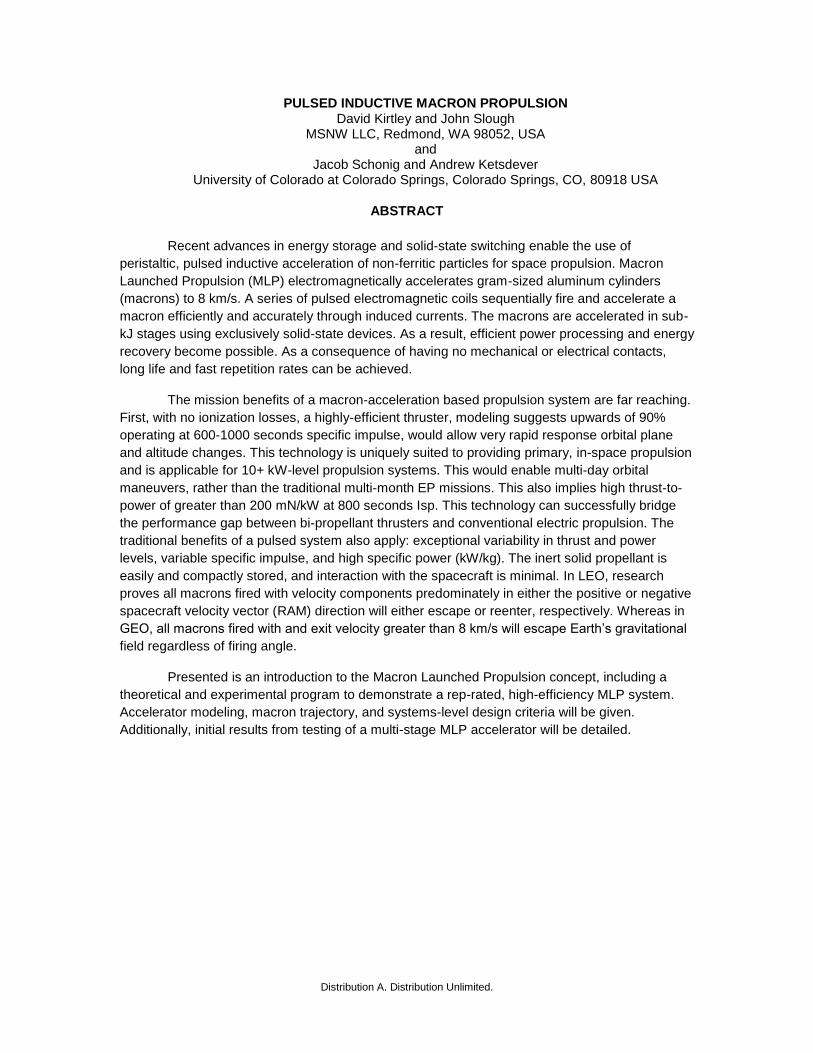
It is critically important for this system to be
utilized in a manner which minimizes its effects on the space environment. Trajectory analysis shows, in general, macrons which are fired with the majority of their velocity directed in either the positive or negative RAM direction, minimize the potential impact on the space environmental. Exit angle and velocity combinations which result in orbital trajectories maximize this system’s impact on the space environment and should be avoided if possible. The three most important factors to consider before each firing must be the macron’s firing angle, exit velocity and the altitude at which the firing will take place. These three parameters essentially dictate the level of a given macron’s impact upon the space environment.
PRELIMENARY EXPERIMENTAL RESULTS
An IR&D program was conducted
at MSNW LLC to investigate the propulsion application of a macron launcher. A six-stage macron launcher was constructed in order to determine the efficiency and accuracy of gram-scale pulsed-inductive launchers. The initial launcher was constructed with six separate coil stages. Each 1.3 cm long stage consisted of a 5-turn 1.9 cm diameter coil made from 13 gauge Litz wire each potted in a low-viscosity epoxy. Each coil was driven with a 600 uF electrolytic capacitor bank switched with six paralleled 1700 V Isolated Gate Bipolar Transistor (IGBT) switches producing a peak current of 24 kA at 1 kV resulting in an axial magnetic field of up to 25. Tesla with a cylindrical macron. Between the coils a high-intensity, 660 nm fiber transmitter/receiver was positioned for velocimetry measurements The initial launcher is shown in Fig. 12. Figure 15 shows an IGBT driver board and fast capacitors. Figure 16 shows the complete 6 board testing setup.
The six stage-launcher successfully
demonstrated the pulsed-inductive acceleration of cylindrical macrons with masses ranging from 1 to 4 grams. Additionally, variable aspect ratio
Figure 12. 6 stage macron launcher.
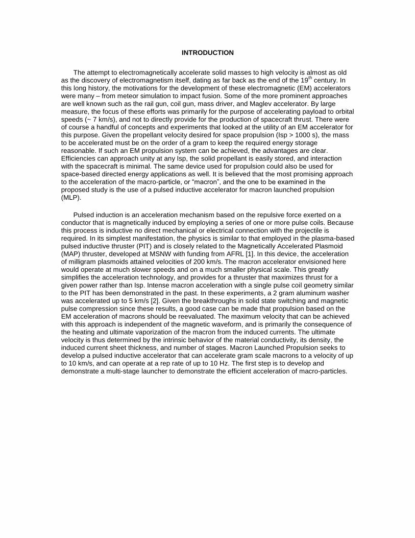
Figure 13. Coil and macron total inductance for cylindrical
and spherical macrons, measured as a function of position.
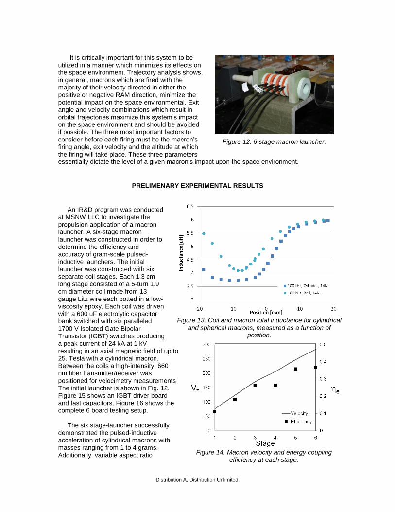
Figure 14. Macron velocity and energy coupling
efficiency at each stage.
cylinders and spheres were examined. The six stage launcher demonstrated a peak velocity of >250 m/s and validated performance expectations for the limited energies tested. Several important characteristics were exhibited. The jitter from sequential launches with different macrons was observed to be near the resolution of the digitizer at a fraction of a microsecond. The macron arrival times
varied by less than 1 sec corresponding to a velocity accuracy of 2 m/s with zero angular distribution. Additionally, velocity could be pre-programmed to less than 5 m/s. An initial position study was performed as it was found that maintaining the initial position of the macron was important in minimizing the jitter as well as the final macron velocity as the accelerator coil sequencing is most challenging at low macron velocities where the magnetic field oscillations were not synchronized well with the macron passage. A key parameter in coupling efficiency is the mutual inductance between macron and the driver coil (see Eq. (2)). As this quantity is difficult to calculate accurately, it was found the most straight forward way was to simply measure it. This was done for both the cylindrical and spherical macrons with the results shown in Fig. 13. The energy coupling is the fraction of kinetic energy to the energy deposited into the coil and for the early stages increases as the macron velocity and current rise time coupling is optimized. The final stage had greater than 40% measured energy coupling as shown in Figure 14. Currently under construction is a 20-board macron launcher that should be capable of up to 1 km/s of final velocity with higher efficiency.
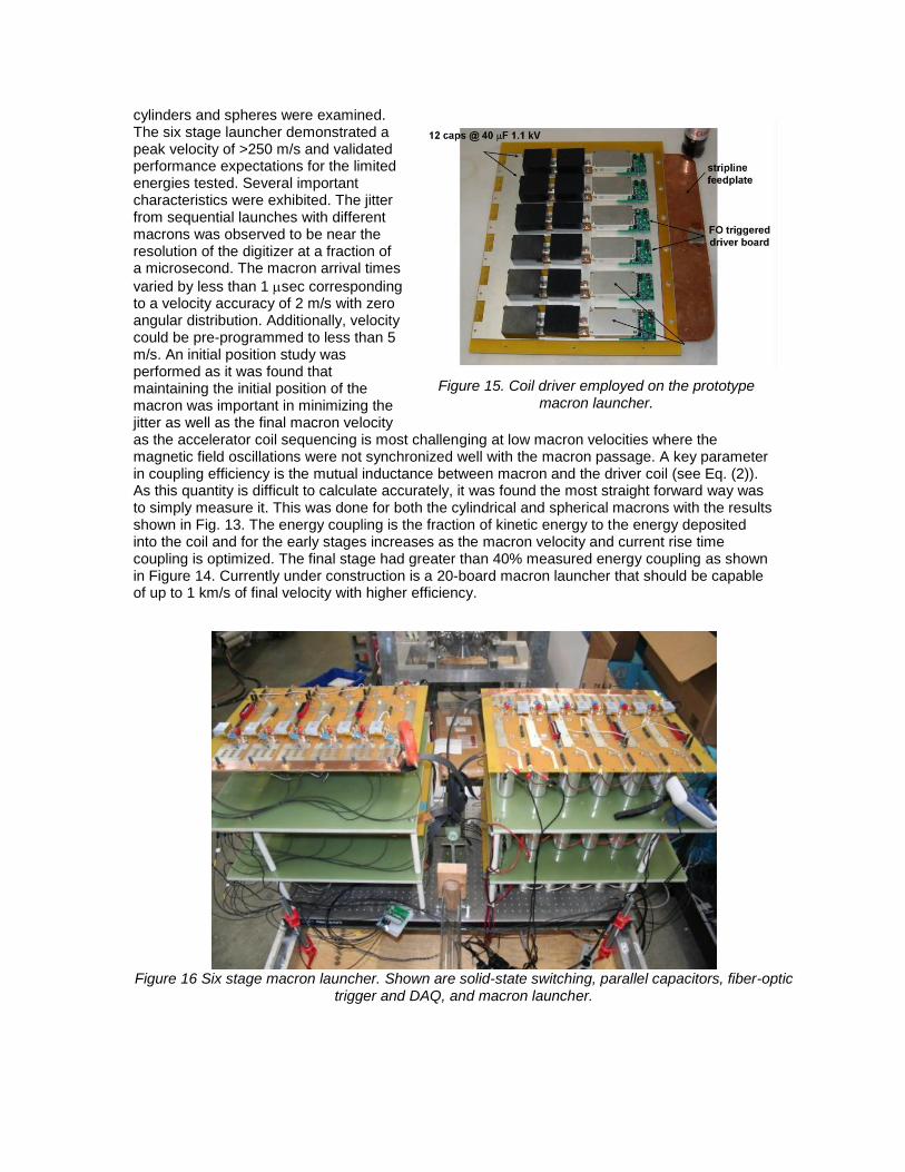
Figure 16 Six stage macron launcher. Shown are solid-state switching, parallel capacitors, fiber-optic
trigger and DAQ, and macron launcher.
Figure 15. Coil driver employed on the prototype macron launcher.

Distribution A. Distribution Unlimited.
REFERENCES
[1]. John Slough, Arthur Blair, Chris Pihl, and George Votroubek, “Magnetically Accelerated Plasmoid (MAP) Thruster – Initial Results and Future Plans”, IEPC paper 2007-16, 30th International Electric Propulsion Conference, Florence, Italy, September 17-20, 2007
[2] Bondelatov and Ivanov, “Ultrahigh axial acceleration of conducting rings”, Sov. Phys. Tech. Phys., Vol 22. No 2, pg 234 (1977).
[3] Tidman and Massey, “Electrothermal Light Gas Gun”, IEEE Trans.Magn. Vol 29. No 1. pg 621 (1993).
[4] H. D. Fair, “Electric launch science and technology,” IEEE Trans. Magn., Vol 39, No 1, pg. 11, (2003).
[5] Barry Marder, “A Coilgun Design Primer”, IEEE Trans.Magn. Vol 29. No 1. pg 701 (1993).
[6] P Lell, E Igenbergs and H Kuczera, “An electromagnetic accelerator”, J. Phys. E: Sci. Instrum., Vol. 16, pg 325 (1983).
[7] G. Votroubek, J. Slough, S. Andreason, C. Pihl, “Formation of a Stable Field Reversed Configuration through Merging”, Journal of Fusion Energy, Vol. 27, No. 1-2, pg.123 (2007)
[8] B. Marder, “A Coilgun Design Primer”, IEEE Transactions on Magnetic, Vol. 29, NO. 1, January 1993
[9] R.J. Kay, E.C Cnare. “Design and performance of Sandia's contactless coilgun for 50 mm projectiles”. IEEE Transactions on Magnetic, Vol. 29, NO. 1/2, January 1993
[10] Eugene C. Cnare, “Magnetic Flux Compression by Magnetically Imploded Metallic Foils”, Journal of Applied Physics, Vol. 27, No. 10, pg. 3812, (1967)
[11] "Modeling Study of the Field-Aligned, Ground-Based Imaging Technique." SAO/NASA ADS: ADS Home Page.
[12] Hastings, Daniel, and Henry Garrett. Spacecraft-Environment Interactions (Cambridge Atmospheric and Space Science Series). Cambridge: Cambridge University Press, 1996.