pulsating flow of non-newtonian fluids in pipes · pdf filepulsating. flow of...
TRANSCRIPT

~"..-..
•
•
-- ----... --.
.;
-.•.r
•
-./ .•
, ;~
'.
PULSATING FLOW OF NON-NEWTONIAN FLUIDS IN PIPES. .•
..,.
\
- bi..... _.'
@ .ESS~?v'l.E.F ..E.I'..SAYEO, B.Sc.(Eng.), M.Sc. (Eng.)
....'.
~ubraitted (0 the ScQ.ool of Graduate Studies\'
in Partial Fulfillment of the Req!1irements
fop the I§egree
•
•
'.-,
A Thesis
Doctor of Philosophy
(0
\
~.
"
'.
.'
•J
-•
McMdSte'r Univ~rsity-Februaryl984
•
,
. '~

L...
-
"
. .
•
'..
PULSATING FLOW OF NO:\,·:\,EWT01\IAN FLUIDS IN PIPES
..
t.
•
•
..
.'
.(
;
DOCTOR OF PKILOSOPHY (1984)(Mechanical Engineering)
~McMaster Un;versityHamilton; Ontario
"
TITLE:
AUTHOR:
SUPERVISOR:
NUMBER OF PAGES
,
Pulsating Flow of Non-Newtonian Fluids in Pipes'
Essam E.F. EI-Sayed. B.Sc., M.Sc.(Eng,) (Al-Azhar University)
Dr. G.F. Round
xvii. 211
J .
,
. .
•
ii ".

•
,
ABSTRACT
The first part of this thesis contains a theoretical formulation and solution for
unsteady nows (pulsatile and start-up 110ws' of non-:'iewtonian time-independent nuids
through rigid pipes. The approach was based on the use of the equation of motion for
axisymmetric unsleady f1o~ofnuids in cylindrical coordinates. In the case of pulsating now,
the unsteady behaviour of the pressure gradient was considered to be described by a periodic
, function of time, ofsinus.oidal form, added to a stationary pre~suregradient, while for start-up
f10w the f1uid was assumed to start its transient motion from rest due to instantaneous and, '
sudden imposition of a stationary pressure gradient. The constitutive equation of generalized
Bingham nuids was used since it represents the majority of time-independent l1uids,
A grid was imposed on the now field in 'order to ohtain a system of equat'ions in. .
linite difference form. The use of finite difference techniques pfl}\'ided dptailed information
about the time deformation of the pulsating and start-up velocity proliles as well a;>y.aluable
information about energy consumption and f10wrates under different pulsating flow
conditions. The results are presented in the most general form so that they are widely
applicable to any case where the 'assumptions and the boundary conditions are all satisfied.
The main conclusion which can be drawn from the theoretical results is thaLthe hydraulic
power required to transport a !luid in pulsatin~ now is never less than that required for the
same nowrate under steady 110'w conditions for -all l1uids except thos,: which exhibit yield
stress. i.e .. Bingham fluids.
On the experimental .-.;idc, ,an in\'cstig~llion of pulsating flow of solid~liquid
mixtures is presented. Solid-liquid mixtures are divided into two types, homogeneous
:-;uspcnsions and psclld~homog:cneous/hctcro'gcneousslurries. The terms homogcneou~and
pscudohomogeneous arc used when sol ids concentration gradicht along pipe vertical axis is
iii

..
constant for homogeneous nows and almost constant for pseudohomogeneous nows; while the
term heterogeneous represents the cases where appreciable solids gradient along pipe vertical
axis exists.
The experiments were carried out for two types of solid-liquid mixtures. The first
was a benton~lay-water suspension with weight concentration ranges fr~m 2.9~o to
11.2%, while the .econd has coal/water slurry with weight concentrations between 5.34%-.
53.7%.
The main·aim of the experimental rig was to create a sinusoidal pressure gradient.
The experimental set-up allowed different ranges of different now parameters to be adopted,
these were:
I. Pulsing frequency ranging between 0·1.25 Hz.
2. Pulsing amplitude (axial deformation of rubber bellows) of34.6, 52.1 and 76.2 mm.
3. , Average !low velocity at 1.63.2.18, and 2.63 mlsec.\
The effe~l1l(differentcombinations of these parameters on the ratio of the hydraulic power in
pulsating now\o that in steady now for the same throughput was s.tu~i.ed.
(
'.
-- .--,\I
IJ
/
(
..
.'
iv
•
..""·...·-·T
•
ACK~OWLEDGE~E~TS
The author wishes to express his si;'cere gratitude and indebtedness to his
supervisor, Dr. G.F. Round, whose helpful advice, va.luable discussions and continuous
encouragement made the completion of this work possible..
Thanks are extended to the men of.the ~cMasterUniversity ~achine Shop fo~ the
construction of the test rig.
For his assistance during the construction of the microcomputer, ~r. J. Verhaeghe
receives the author's deepest gratitude.
Thanks also are due to the Mc~lastcr University Engineering Word Processing
Centre for typing the manuscript.
The financial support provided by the ~atural Sciences and Engineering Research
Council of Canada is acknowledged.':"
Finally, I would like to express my special appreciation to may wife Kefah for her. 0
support and encouragement during this work.
•
•
v
•..
.'.
LIST OF CO:-iTE:-i,S
Abstract
Acknowledgements
List ofContents
List of Figures
List ofTables
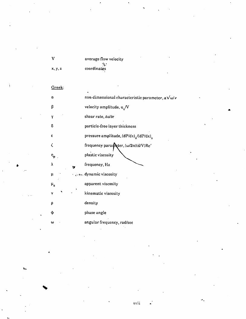
~omenclature
Chapter 1 I:-iTRODCCTIO:-i
Chapter 2 LITERATCRE REVIEW
iii
vi
ix
xiv
xv
2.1
2.2
2.3
Introduction
Steady Flow of Homogeneous ::-ion-Newtonian Fluids
Cnsteady <Pulsatile and Oscillatory) Flow of:-iewtonian and :-.ion-Newtonian Fluids
I;
7
11
Steady Flow oflleterogeneous Slurries2.4
2.3.12.3.2
Pulsatile Flow of:-iewtonian FluidsPulsatile Flow of :-.lon-Newtonian Fluids
1126
29
2.5 Pulsatile Flow of Heterogeneous Slurries 34
Chapter 3 SCOPE OF INVESTIGATION 39
Chapter 4 A TIIEORETICAL TRI';A'DIE:\T OF C:-iSTEADY LA:'.II:-iAR FLOWSl:-i PIPES CSI1IiG A GE:-iERALIZEDBINGIIA.\\.\\ODEL 41
4.1
4.2
Introduction
Derivation of Steady Flow Correlation
VI
41
42
4.3 Velocity Distribution in Steady Laminar Flow 50
4.4 Mathematical Formulation for L'nsteady Laminar Flow 52
4.5
4.4.1 Governing Equations4.4.2 Determination of Flow Patterns4.4.3 Determination of Flowrate4.4.4 Determination of Power Requireme~s
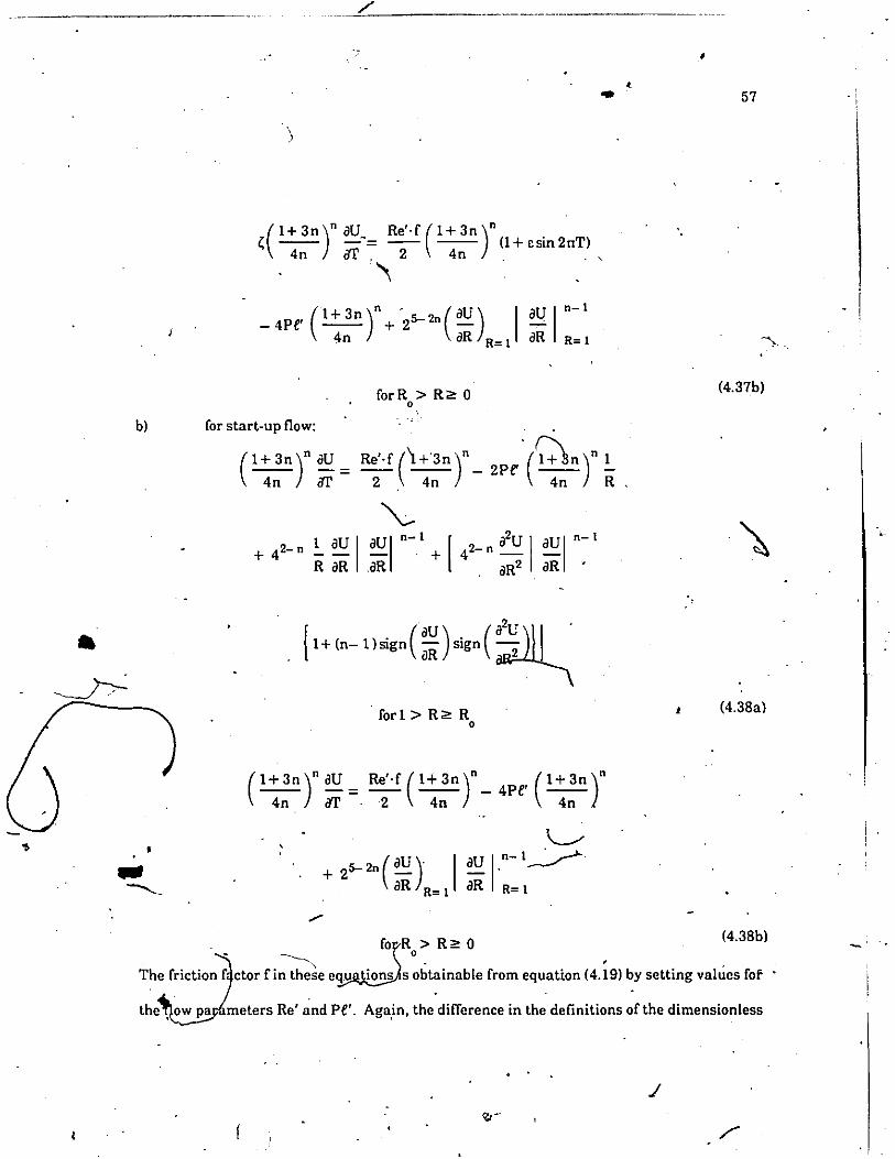
Finite Difference Formulation ~(
5253.5859
61
Chapter 5 EXPERIMENTAL PROCEDL'RE 63
Introduction
64
63
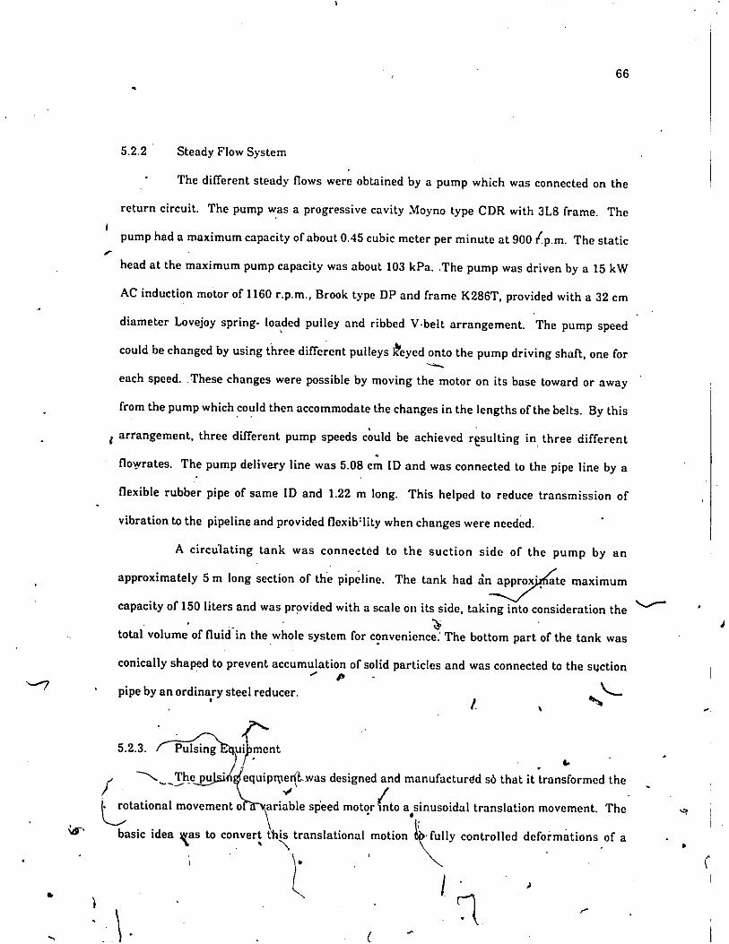
64666669
The PipelineSteady Flow SystemPulsing EquipmentMeasuring Instrumentation and the Microcomputer
Deyription of the Installation
5~.15.2.25.2.35.2.4
5.2
5.1•
5.3 Bentonite Clay-Water Suspension 70
5.4 Coal-Water Slurry 73
5.5 Calibration of Measuring Instruments 73
5.5.15.5.2
Calibration of Pressure TransducerCalibration of Flowmeter
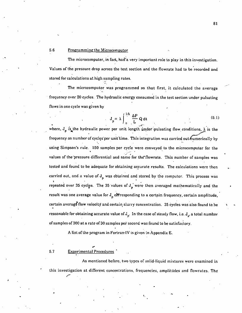
5.6 Programming the Microcomputer 81
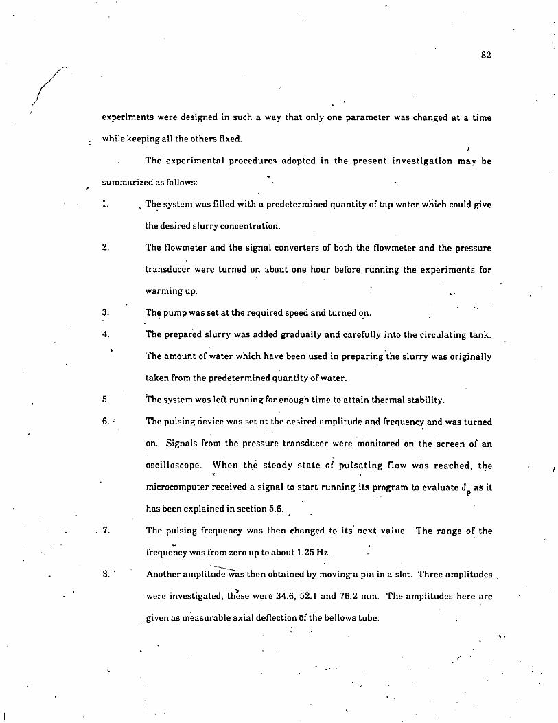
5.7 Experimental Procedures 81
Chapter 6 RESULTS OF FINITE DIFFERENCE SOLUTIONAND DISCUSSION 84
6.1 Pulsating Flow 84
6.1.16.1.26.1.36.1.4
Velocity ProlilesFlowratesHydraulic Power RequirementsPhase Angles
84939799
6.2 Start-up ~-Iow 99
•
vii•

\
Chap~r 7 EXPERL\1EXTAL RESl:LTS A:-iD DISCl:SSIO"
7.1 Bentonite Clay-Water Suspension
7.1.1 Pulsing Frequency and Pulsing Amplitude7.1.2 Effect of Solids Concentration7.1.3 Effect of Avera"e Flow Velocity
',' 7,2 Coal-Water Slurry
7.2.1 Effect of Pulsing Frequency7.2.2 Effect of Pulsing Amplitude7.2.3 Effect of Average Flow "'elocity r-v7.2.4 Effect of Solids Con~entration
7.3 Limitations
Chapter 8 CONCLl:SIONS AND RECOMMENDATIONS
8.1 Conclusions
8.2 Suggestions fo,' Further Studies,
REFERE"CES
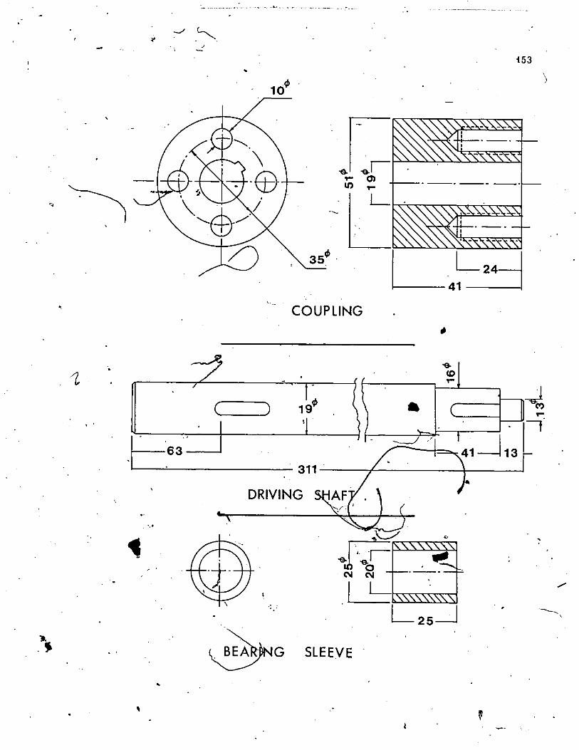
•APPE~DIX A DETAILS OF PUL~I:--iGEQl:IP:\,IENT
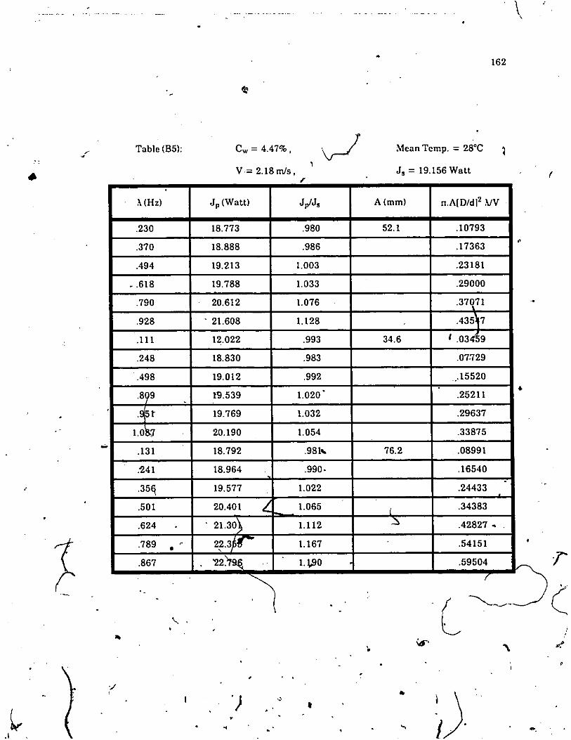
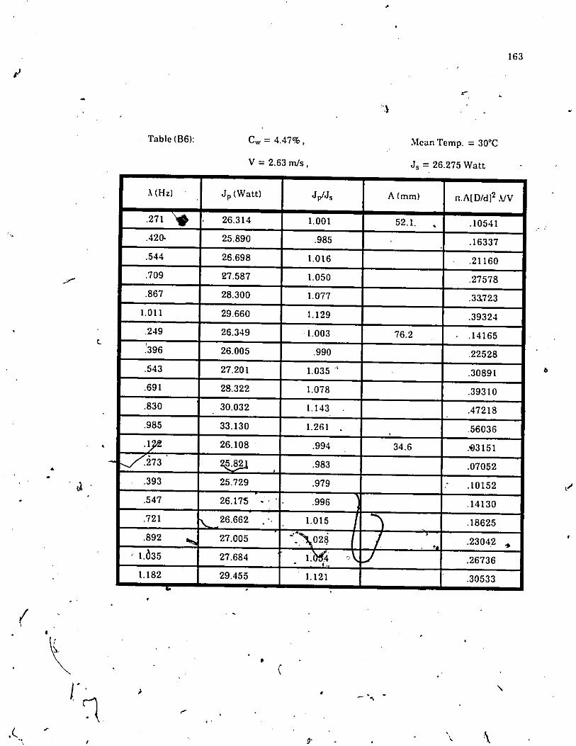
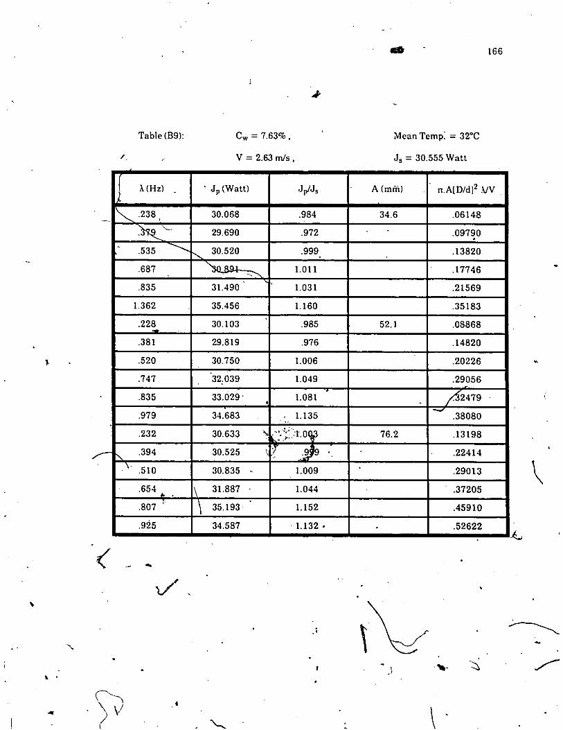
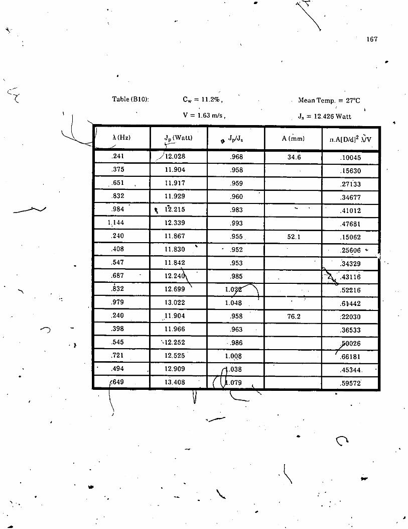
APPE"DIX B pr;LSATING FLOW DATA Of' BENTONITECLA Y-W~TER Sl:SPENSION
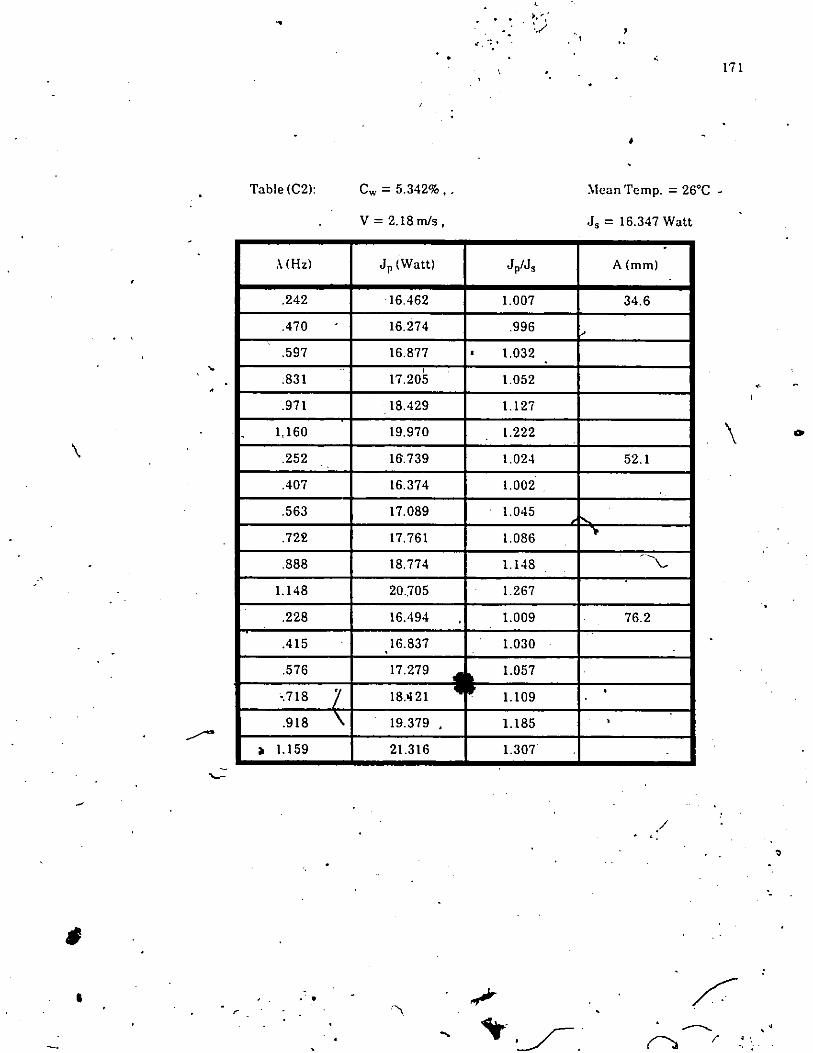
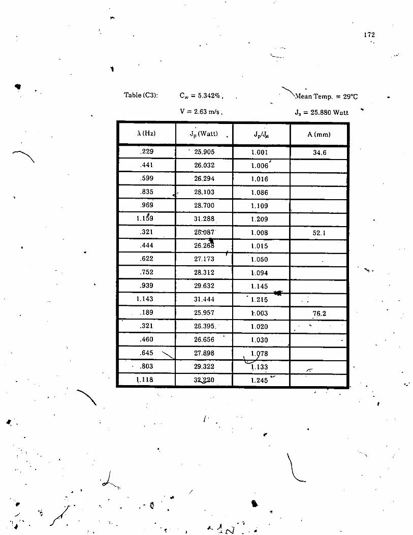
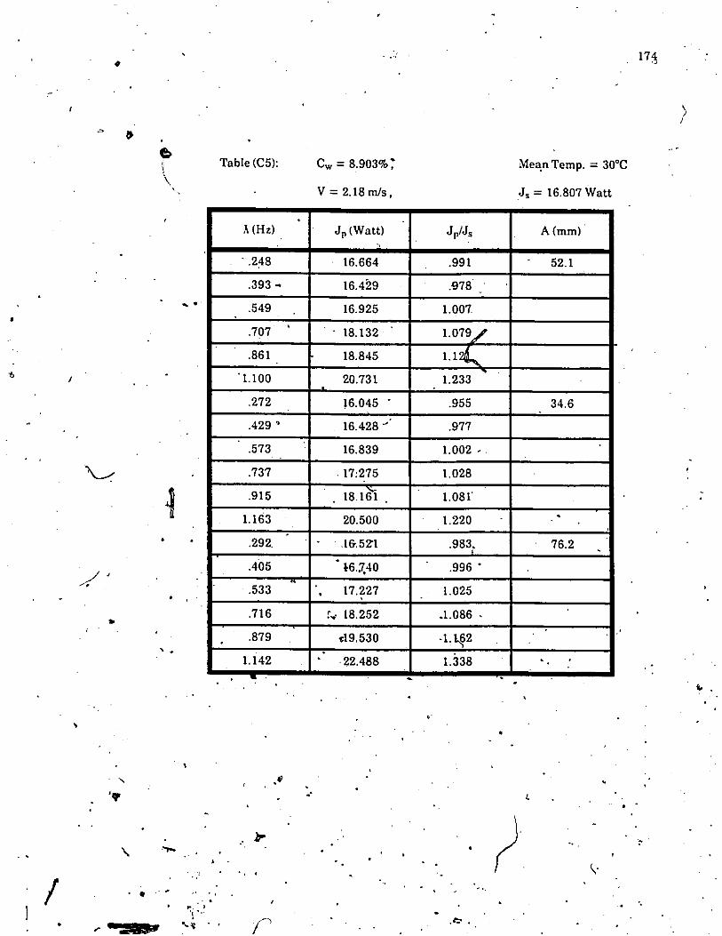
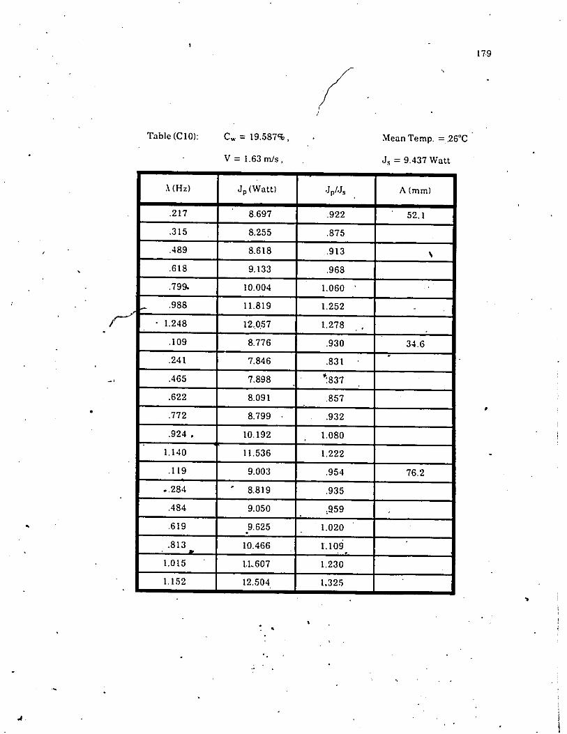
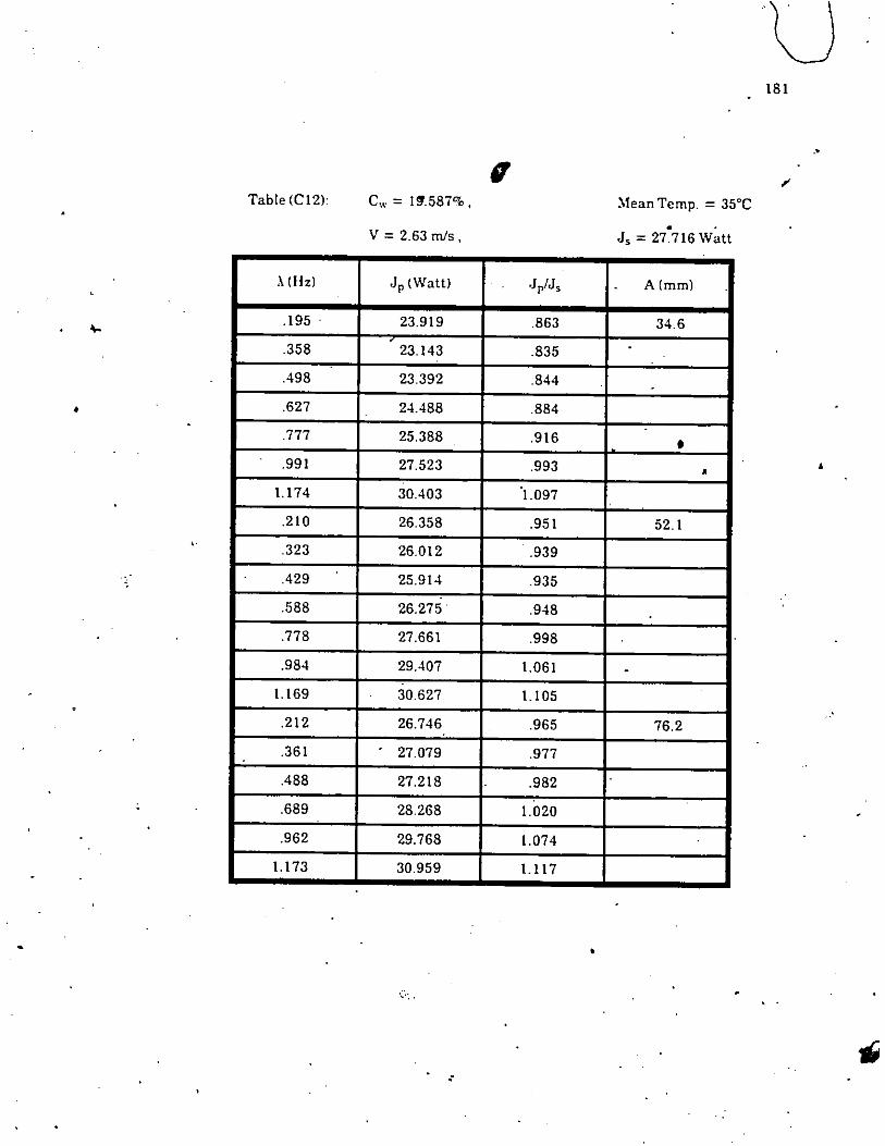
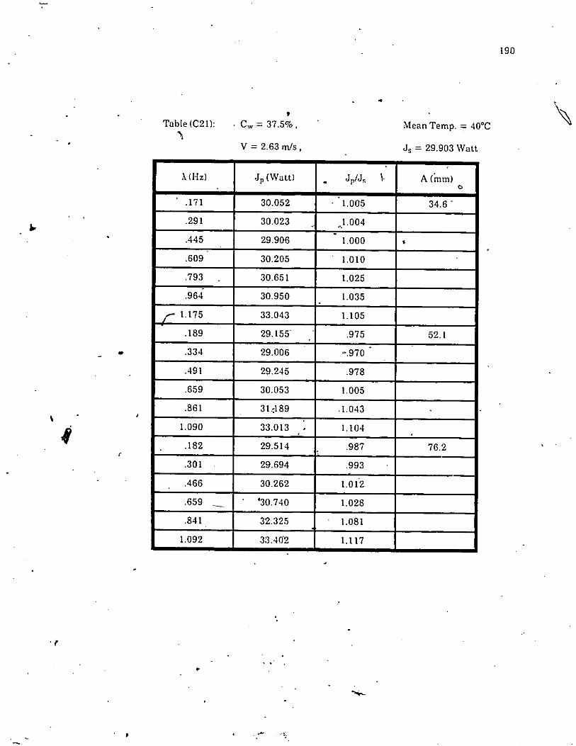
APPENDIX C PULSATING FLOW DATA OF COAL-WATERSLI.JRRY
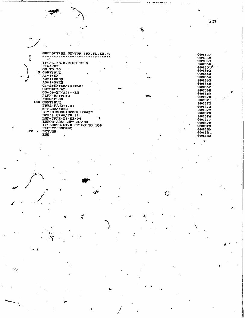
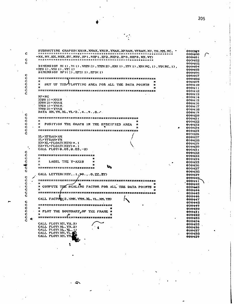
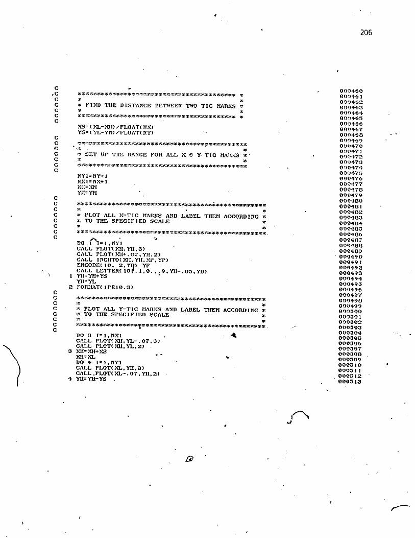
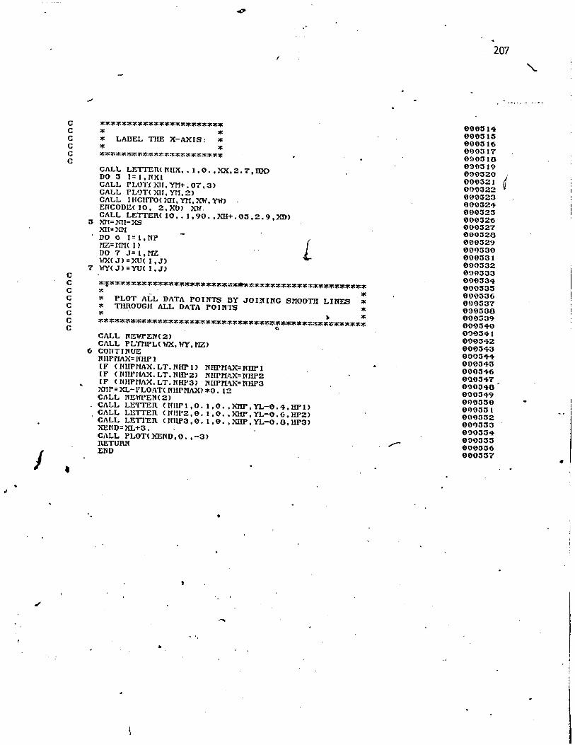
APPEXDIX D COMPl:TER PROGRAM FOR FINITEDIFFERE:--iCE CALCULATIONS
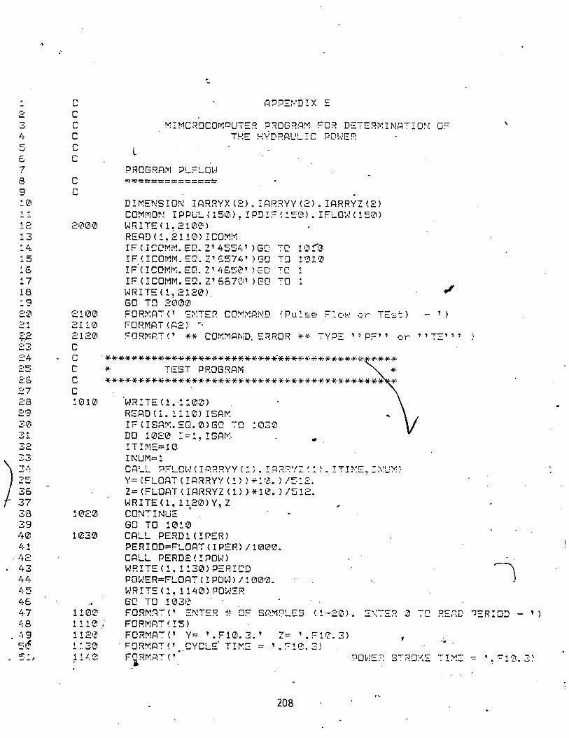
APPE"DlX E ':VIlCROCO:VIPl:TER PROGRA:VI FOR EXP~:Rl:\'IENTAL
DETER:VIl"ATIO:--: OF HYDRAULIC POWER
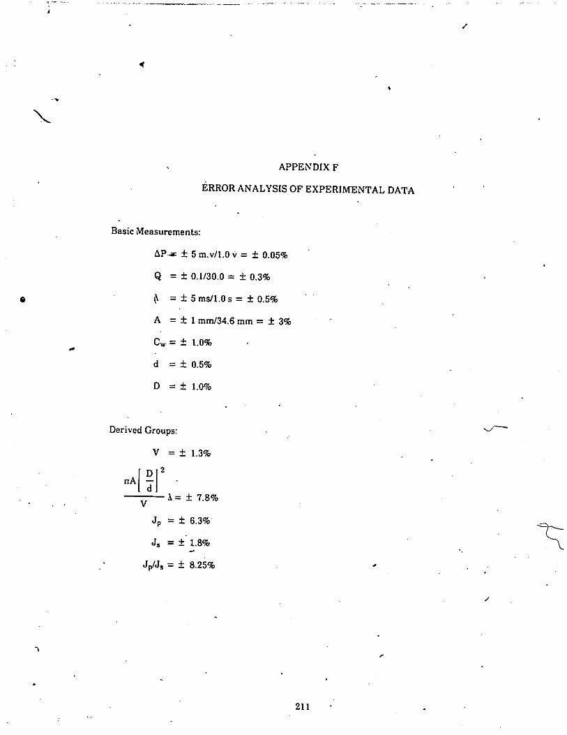
APPENDIX F ERROR A"ALYSIS OF EXPERmENTAL DATA
\"111
105
105
!f)5117118
121
122133134135
138
140
140
143
146
152
158 '
170
195
208
211

•
,...
"iV
LIST OF FIGC-RES
FigureTitie Page
.. "'-.2.1 Pressure gradient vs. now velocity for homogeneous suspensions 8..2.2 Transitions of velocity profiles for pulsating flows.
1&~E"rom .\Iuto and :\akane [37}.
"- 2.3 Critical Reynolds number vs. dimensionless velocity.E"rom Gilbrech lind Combs [-121. 18
2.-1 Critical Reynolds num.ber vs. velocity amplitudeJor various valuesof frequency parameter a (harmonic oscillation I.E"rom Sarpkaya [4-11. 19
2.5 Comparison of measured with theoretical results in an oscillatingpipe flow (Run 1). E"rom Ohmi and I~uchi [51}. 24
2.6 Comparison of measured with theoretical results in an oscillatingpipe flow (Run 21. E"rom Ohmi and Iguchi [511. 25,
~, . .
?- Comparison ofmeasufcd with t.heoretical results in an oscillating.... 1.
pipe flow IRutr31. E"rom Ohmi and Iguchi [511. 25
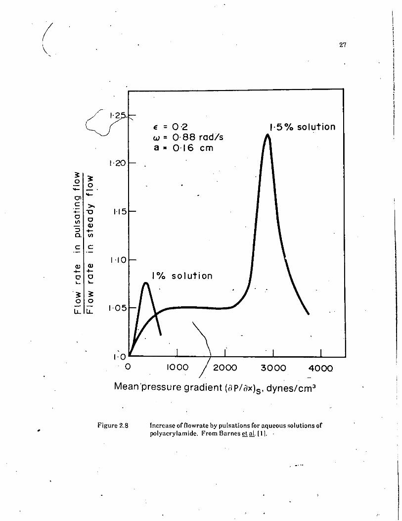
2.8 Increase offlowrate by pulsations for aqueous solutions ofpolyacrylamide. From Barnes et al. [11. - 27
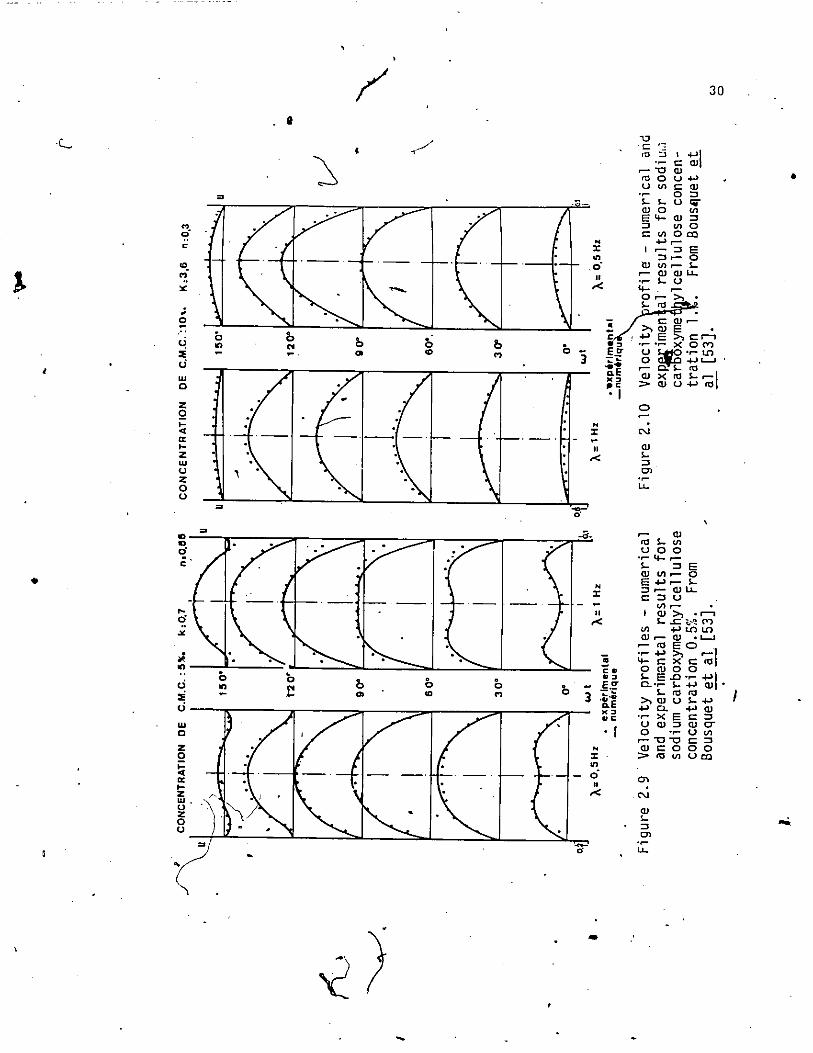
2.9 Velocity profiles - numerical and experimental results forsodium carboxymethylcellulose concentration 0.5%.
.From Bousquet et al. [531. 30
2.10 Velocity profiles - numerical and experimental results forsodium carboxymethylcellulose concentration 1%.From Bousquetet al. [531. 30 ,
2.11 Increase in flowrte at different pulsing frequencies for visco-elastic fluid. From Walters and Townsend [21. 31
2.12 Pressure grad'ient vs. now velocity for heterogeneous slurries. 36•
2.13 E"ormation of particle-free laye,' in pulsating llow ofheterogeneous slurrie.s. 36
2.1-1 Ratio of hydraulic energy of pulsating flow to that of steady llowas a function of pulsing frequency for sand-water ;lurries.E"rom Round [51: 38
", ,..... '.~
U toy relation for a generalized Bingham fluid. ·-13
- -. ,

4.2
4.3
4.4
4.5
5.1
5.2
5.3
5.4
Flow ofa Bingham fluid in a circular pipe.
Solution ofequation (4.12) - for n =0..5, 1.0, 1.5 and 2.0.
Comparison ofexperimental data for laminar flow with equation,(4.12). Top bracketed data from ref. [91; botto/" bracketed datafrom ~ef. [861. , •
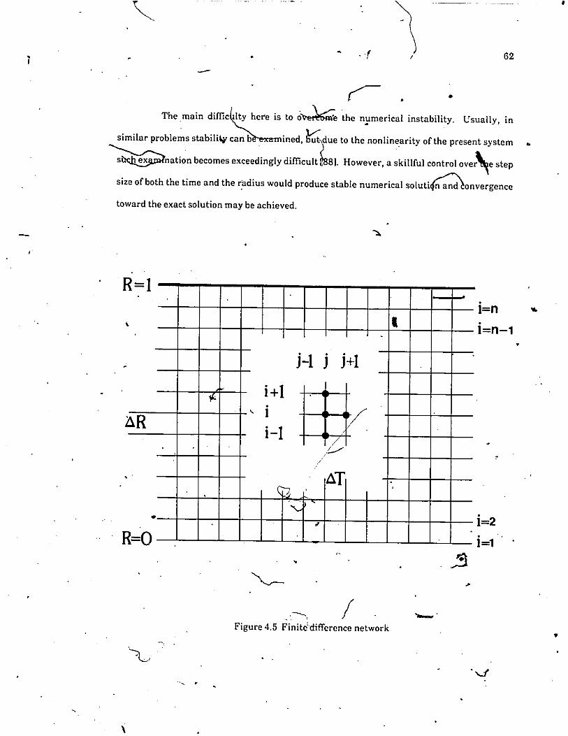
Finite difference network.
Schematic diagram ofexperimental pipe loop.· .
Schematic dia"gram of pulse generating mechanism.
Shear stress vs. shear rate for bentonite clay·water suspensiortsat different solids weight concentrations (obtained by Haakeviscometer).
· Coal particle size distribution.
43
47
48
62
65
68
71
74
5.5
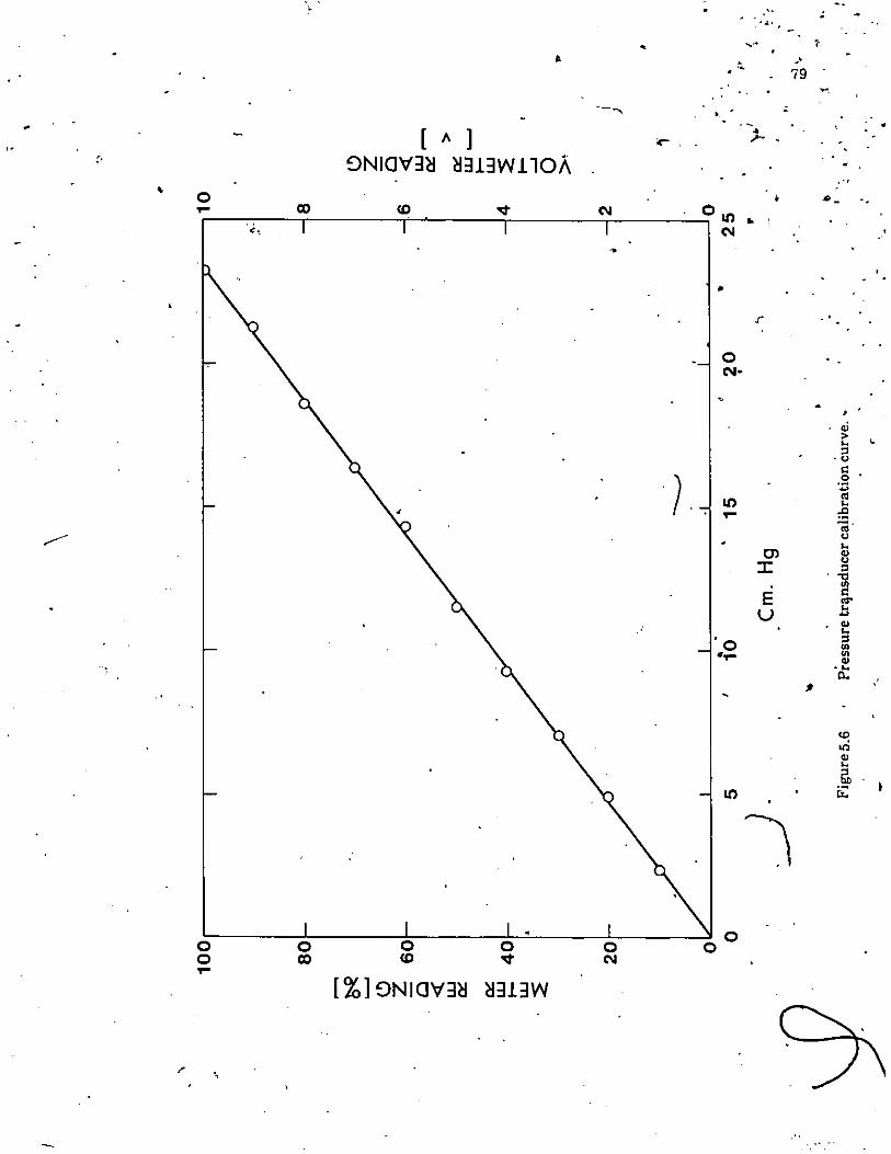
5.6
5.7
Photomicrograph ofa 'coal sample.\ ..
Pressure transducer calibration curve.
•Flowmeter caiibration curve.
•75
79..80
"
'.
6.1
6.1cont.
6.2
)6.3
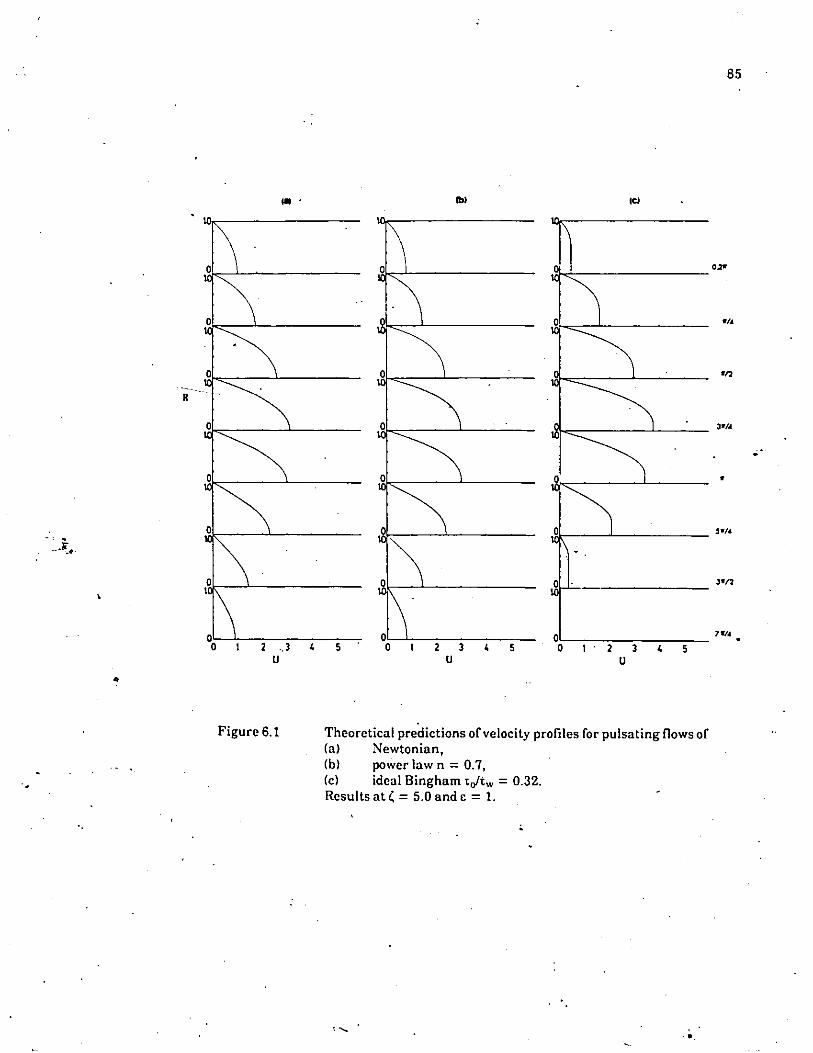
Theoretical predictions ofv~locity profiles for p'llsating !Jows of(a) Newtonian,(b) power law n =0.7,(c) i<jeal Bingham tJtw = 0.32.Results at <= 5.0 and. = I.
(d) generalized Bingham n = 0.7 and tJtw =0.32,(e) ideal Bingham tJtw = 0.44,(0 generalized Bingham n =0.7 and tJtw =0.44.Results at <= 5.0 and. = I.
· Theoretical predictionS';;f'velocity profiles for pulsating flo.wsofan ideal Bingham fluid at different frequencies.
. .,:{a) <=. 4.0, '-,(b) <=7.0,(c) <=; 10Results at tJtw =0.44 and,. = I.
•Theoretical predictions of velocity profiles for pulsating flowsof a generalized Bingham fluid at different frequencies.(a) l; =4.0,· ((b) l; = 7.0,(c) l; = 10Results at n = 0.7, toltw = 0.44 and·. = I.
8~
86
89
>.....90
.'
\
•
\"

6.4 Theoretical predictions of velocity profiles for pulsating flowsofa generalized Bingham fluid at difTerent amplitudes.
______ (a) c = 0.5,(b) c = L,(c) c = 1.5,(t» c = 2.Results at n = 0.7, tohw = 0.32 and ~ = 7.
Theoretical predictions ofdimensionless pulsating flowrates S vs.dimensionless frequency ~ (c = 1).
Theoretical predictions.ofdimensionless pulsating hydraulicpower requirements E vs. dimensionless frequency ~ (c = 1).
92
94
96
.'
•
6.9
6.10
.~
6.11
7.1
7.2
7.3
7.4
J .
•
,
Theoretical predictions of phase angle 4> vs. dimensionlessfrequency ~ (c ~ 1). f
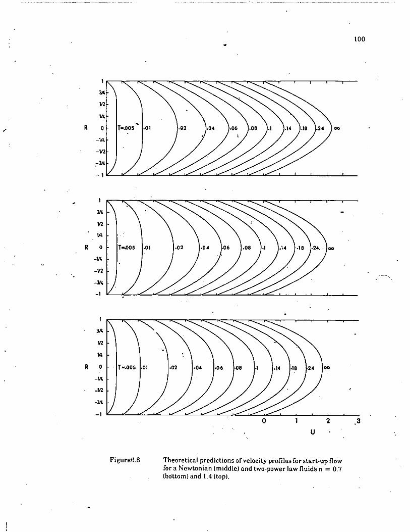
The~etical predictions of velocity profiles for start-up flowfor a~ewtonian (middle) and two-power law fluids n = 0.7(bottom) and 1:4 (top). .
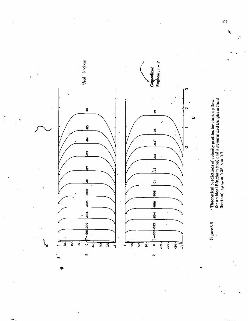
.Theoreticalf:rdictions of velocity profiles for start-up flowfor an ideal ngham (top) and a generalized Bingham fluid(bottom), to t'w = 0.32, n.= 0.7.
Theoretical predictions of velocity profiles for start-UIl11owfor an ideal Bingham ltop) and a generalized Bingham fluid(bottom), tohw = 0.44, n =0.7.
Velocity development as a function ofdimensi"nless time Tob' the pipe centerline for start-up flcw..".[,Newtonianand non-Newtonian fluids. .~
Output signals from the pressure transducer at difTerentpulsing frequencies (A = 52.1 mm)
•~ H'ydraulic power ratio of pulsating to steady flow vs. pulsingfrequency. Experimental results for bentonite c1'l,Y-water _suspension lCw =2.97%).
Hydraulic power ratio of pulsatil)g to steady flow vs.dimensionless velocity amplitude. Experimentall'esults for bentoniteclay-water suspension lCw = 2.97%1.
Hydraulic power ratio of pulsating to stcady flow vs. pulsingfrequency. Experimental results for bentonite clay-watersuspension lC w = 4.47%).
Xl
98•
100
101
102
'.
104
106
109
110
111
..

f,
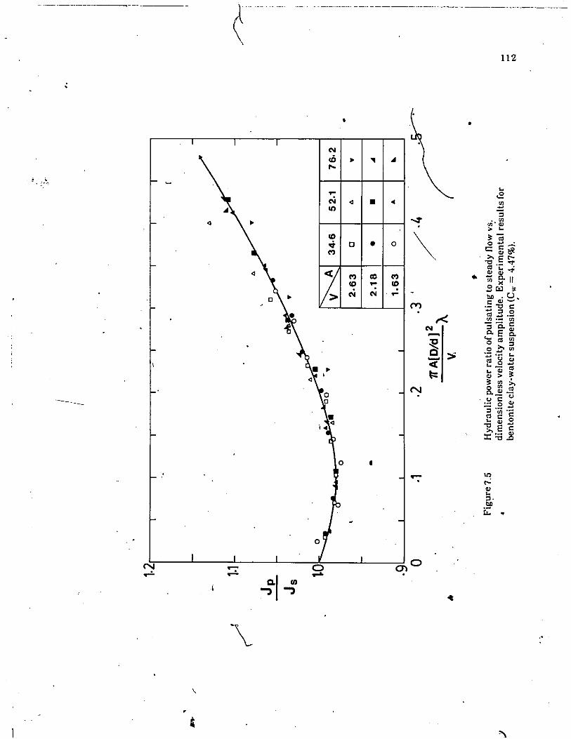
7.5 Hydraulic power ratio of pulsating to steady flow Ys.dimensionless velocity amplitude. Experimental results forbentonite clay-water suspension (Cw = 4.47%). '112
7.6 Hydraulic power ratio ofpulsating to steady flow vs. pulsingfrequency. Experimental results for bentonite clay-watersuspension (Cw = 7.63%). 113
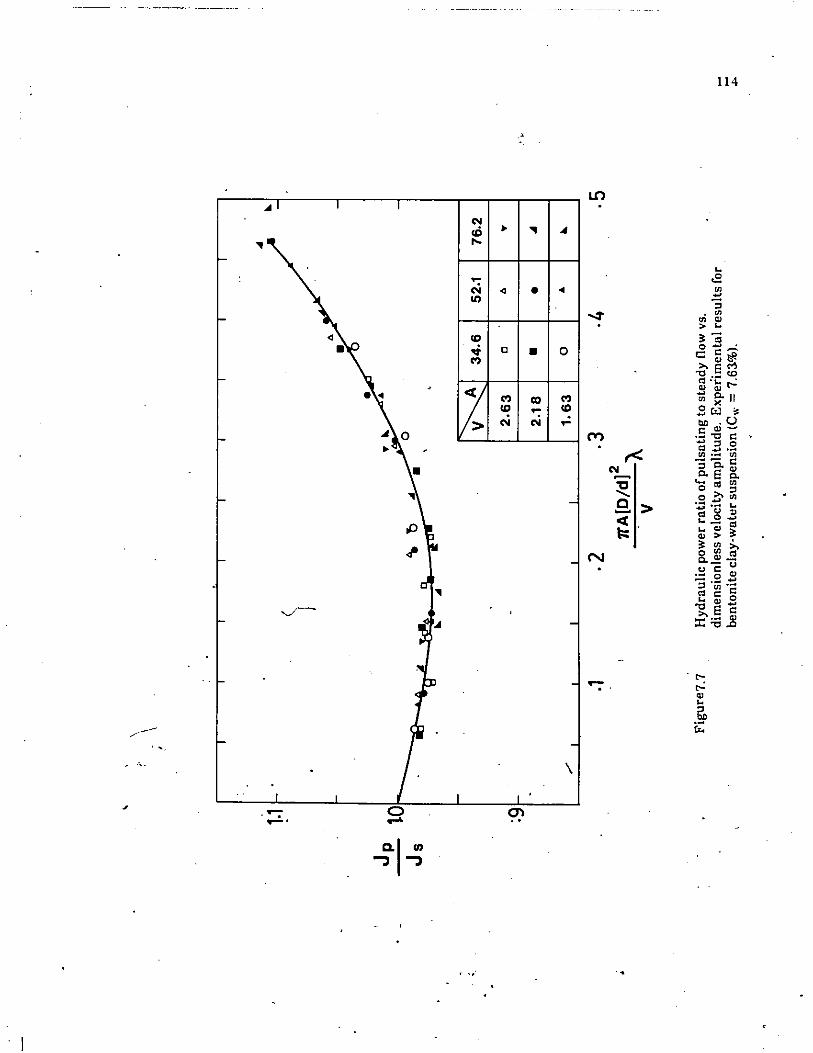
7.7 Hydraulic power ratio of pulsating to steady flow vs.dimensionless velocity amplitude. Experimental re""lts forbentonite clay-water suspens~on(Cw = 7.63%). 114
7.8 Hydraulic power ratio of pulsating to steady flow vs. pulsingfrequency. Experimental results for bentonite clay-watersuspension (C w = 11.2%). 115
./ 7.9 Hydraulic power ratio of pulsating to steady flow vs.dimensionless velocity amplitude. Experimental results forbentonite clay-water suspension (Cw = 11:2%). 116
I • : ':" oJ'
7.10 Hydraulic power ratio of pulsating·to steady. flow vs. pulsingfrequency. Experimental results for coal-water slurry(Cw = 5.34%). 124
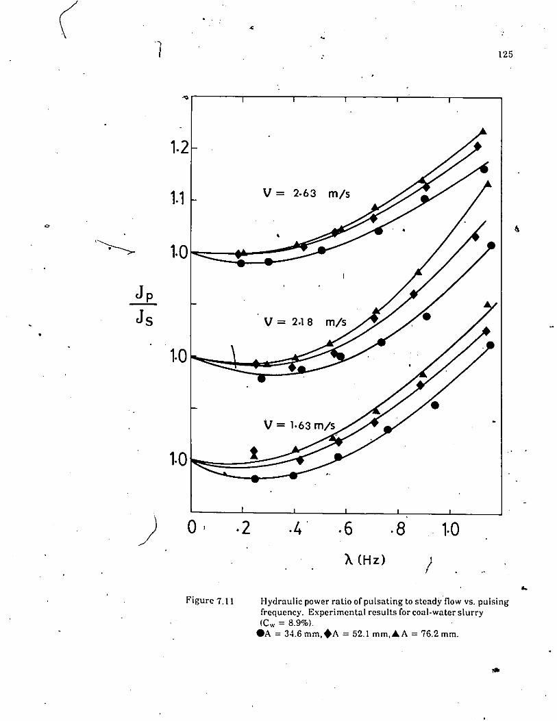
7:-1.1 Hydraulic power ratio of pulsating to steady flow vs. pulsingfre.quency. Experimental results for coal-water sl urry(Cw = 8.9%). 125
7.12 Hydraulic power ratio of pulsating to steady flow vs. pulsingfrequency. Experimental results for coa!-water slurry(Cw = 14.25%). 1~6
7.13 . Hydraulic power ratio of pulsating to steady flow vs. pulsing..frequency.,Experimental results for coal-water slurry •(Cw = 19.59%). • ·127
'~4 Hydraulic power ratio of pulsating to steady flow vs. pulsingfrequency. E"perimental results for coal-water slurry(Cw = 24.93%). 128
7.15 Hydraulic power ratio ~fpulsatingto steady flow vs. pulsing
ftrequency. Experimental results for coal-water slurry ,(Cw = 30.27%). 129 ,
7.16 Hydraulic power ratio of pulsating to steady flo\~ vs. pulsingfrequency. Experimental results forcoal'water slurry ,.,(C w = 37.5%). 130

..
...
7.17
7.18
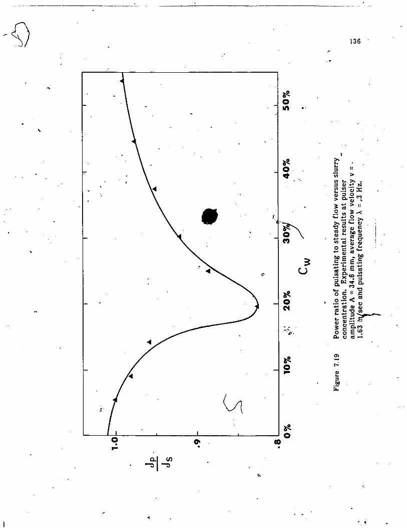
·7.19
•
~
Hydraulic power ratio ofpuf'jating to steady flow vs. pulsingfrequency, Experimental results for coal-water slurry(Cw =44.64%).
Hydraulic power ratio of pulsating to steady fl~w vs. pulsingfrequency. Experimental results for coal-water slurry(C w = 53.7%). . \.
Hydraulic power ratio of pulsating to steady flow vs. solidsweight concentration. Experimental results for coal-water slurry.Experimenpalesults at pulsing a'!lplitude A =34.6 mm, averageflow velocit = 1.63 mls and pulsing frequency A = 0.3 Hz.,
•
•
xiii
131
132
136
·v

-c ..•
LIST OF TABLES
• TableTitie
Page
5.1 Physical properties of bentonite clay-water suspensions atdifferent weight concentrations. 72
5.2 Coal particle size distribution. 76
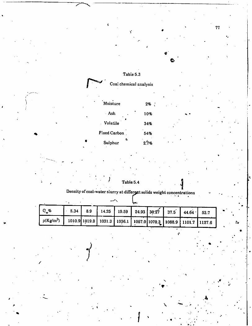
5.3 Coal chemical analysis. 77
5.4 Den·sity ofcoal-water slurry at different solids weightconcehtrations. 77
>6.1 Velocity profiles during the first six cycles for a generalized
Bingham material with n = 0.7, <oI<w = 0.32; and at<= 10, C = 1.0. 87
7.1 Values of Reynolds number and Plasticity number at differentflow velociti~d solids weight cpncent,ations. 119
•
.'
?•
•
xiv
*.