published online december-january 2016 in ijeast (http
TRANSCRIPT
International Journal of Engineering Applied Sciences and Technology, 2016 Vol. 2, Issue 2, ISSN No. 2455-2143, Pages 93-102 Published Online December-January 2016 in IJEAST (http://www.ijeast.com)
93
MODELLING AND ANALYSIS OF NONLINEAR
RESIDENTIAL LOADS FOR THD STUDY AND
ITS MITIGATION STRATEGY
T.Murali Mohan K.Rajesh Babu Asst. Professor PG Student
Department of EEE Department of EEE
JNTUK, Kakinada, AP, India JNTUK, Kakinada, AP, India Abstract— This paper deals with modelling of most of the
nonlinear domestic loads like TV, Home UPS, CFL lamps,
ASD washer and computer etc. Due to the advancement in
power electronics industry, home appliances become more
power electronics based. The widespread use of these
nonlinear loads increases the harmonics in distribution
systems and affects the voltage quality of power system.
Harmonic analysis of the distribution system with
nonlinear loads is essential for designing and optimal
location of filters. In order to assess the harmonics
produced by nonlinear loads precisely, accurate modelling
of these loads is required. Simulation models are developed
for various nonlinear loads using MATLAB-SIMULINK
software. THD analysis is performed and the effect of filter
and zigzag transformer on harmonic distortion is assessed.
Keywords— THD, UPS, CFL, Zigzag Transformer, ASD
PC, Harmonics, SMPS
I. INTRODUCTION
Harmonics are the by-products of modern electronic devices
i.e. nonlinear loads, this harmonics by drawing current in abrupt short pulses, rather than in a smooth sinusoidal manner.
Any distribution circuit feeding nonlinear loads will contain
some degree of harmonic frequencies in multiples. Due to the
rapidly increasing number of non-linear loads in distribution
systems, the harmonic distortion of the current and voltage
increases [1], [15]. Examples of non-linear loads are personal
computer, fan with TRIAC [5] as regulator, television set
(TV), fluorescent tube with electronic ballast, compact
fluorescent lamp [4], battery charger, uninterrupted power
supply (UPS) [6] and any other equipment powered by
switched-mode power supply (SMPS) [2] unit. A term generally deployed to compute the harmonic pollution is Total
Harmonic Distortion (THD) which can be defined as: “The
ratio of the harmonic content to the fundamental quantity,
expressed as a percentage” [9]. As the number of harmonics-
producing loads in residences has increased over the years, it
has become increasingly necessary to address their effects on
the distribution system. Power Quality of distribution
networks is severely affected due to the flow of these
generated harmonics.
Harmonic currents generated by nonlinear loads can cause
problems on the power system. These harmonics can cause
excessive heat in many appliances, and hence reduce the life
span of the distribution transformer supplying such loads,
protecting equipments in power system. It can also increase
power consumption and reduce system efficiency. It also lowers the system power factor. In this paper presents the
results of a SIMULINK of harmonic distortion caused by
different non linear home appliances and analysis of
percentage total harmonic distortion. According to the IEEE
standard, total harmonic distortion in voltage (THDv) and
individual harmonic distortion in voltage (THDv) for the
system voltage level up to 69 kV should not go beyond 5 %
and 3 % respectively [9].
The higher level of harmonic distortion in a distribution
system reduces the efficiency of the system because of the
increased line and transformer losses. In order to reduce the harmonics caused by nonlinear loads in distribution system
filtering action is usually employed which in some cases like
shunt filter may raise the harmonic level instead of lowering
[20]. In this paper the influence of Zigzag transformer on
harmonics is presented as the Zigzag transformer has ability to
cancel harmonics [8] because of its unique connection style.
The zigzag connection is also called the interconnected star
connection. This connection has some of the features of the Y
and the ∆ connections, combining the advantages of both. The
zigzag transformer contains six coils on three cores. The first
coil on each core is connected contrariwise to the second coil
on the next core. The second coils are then all tied together to form the neutral and the phases are connected to the primary
coils. Each phase, therefore, couples with each other phase
and the voltages cancel out. As such, there would be
negligible current through the neutral pole and it can be
connected to ground. One coil is the outer coil and the other is
the inner coil. Each coil has the same number of windings
turns (Turns ratio=1:1) but they are wound in opposite
directions.
The rest of the paper is organized as follows. Modelling of
distribution network with nonlinear residential loads and
International Journal of Engineering Applied Sciences and Technology, 2016 Vol. 2, Issue 2, ISSN No. 2455-2143, Pages 93-102 Published Online December-January 2016 in IJEAST (http://www.ijeast.com)
94
zigzag transformer in SIMULINK is presented in section II.
Experimental results are presented in section III. Concluding remarks are given in section IV.
II. PROPOSED NONLINEAR MODELS
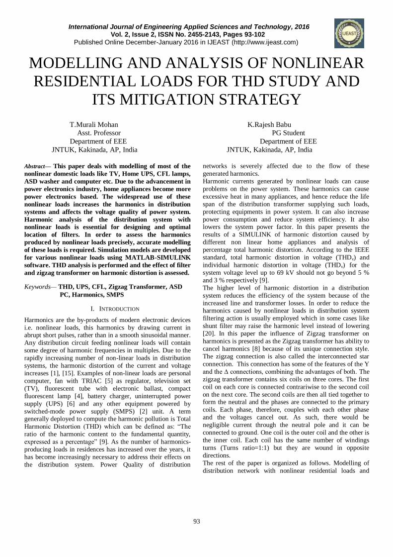
A. Personal Computer –
A typical PC load model as shown in Fig. 1 uses SMPS [2]
and comprises of a full wave rectifier, a DC storage capacitor
C, a diode bridge resistance R and a series RFI choke which is represented by an inductance L. The Fig 1 shows the
personnel computer simulation model and Fig. 2-Fig. 5 shows
Supply Voltage, Current waveforms, voltage and current
THD’s of Personal computer load. The third and fifth
harmonic components are more dominant in the PC current.
The PC's power supply converts the input ac voltage of 50 Hz
to a desired direct current output voltage by means of a single-
phase rectifier circuit. Generally computer loads produce
sharp peaks due to capacitive charging currents drawn by the
power supply.
Fig. 1. Simulation model of PC
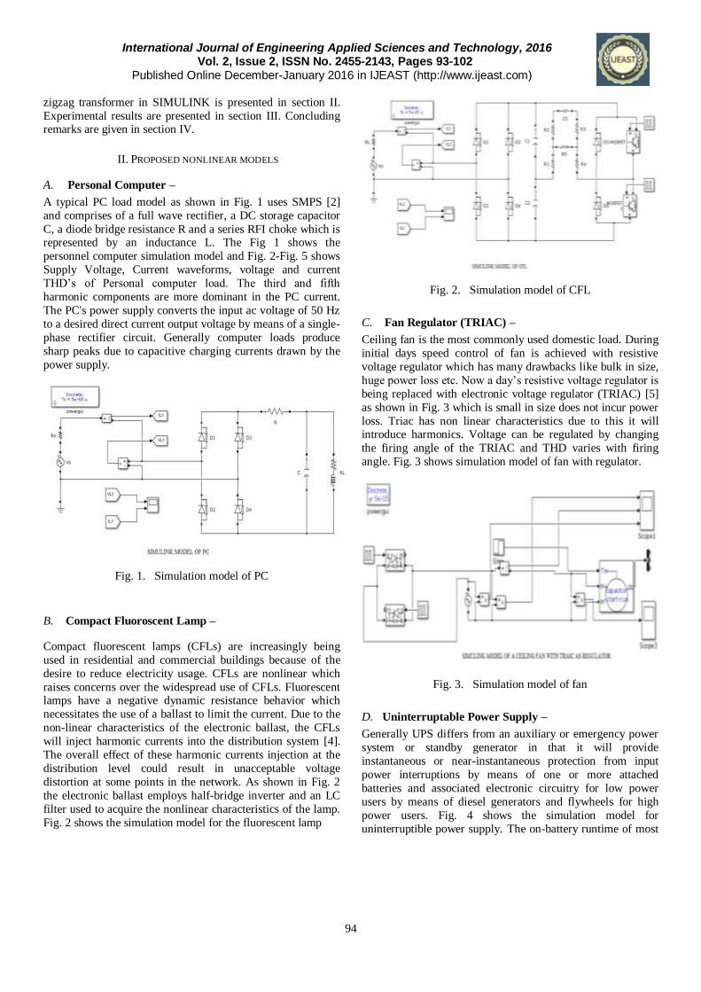
B. Compact Fluoroscent Lamp –
Compact fluorescent lamps (CFLs) are increasingly being
used in residential and commercial buildings because of the
desire to reduce electricity usage. CFLs are nonlinear which
raises concerns over the widespread use of CFLs. Fluorescent lamps have a negative dynamic resistance behavior which
necessitates the use of a ballast to limit the current. Due to the
non-linear characteristics of the electronic ballast, the CFLs
will inject harmonic currents into the distribution system [4].
The overall effect of these harmonic currents injection at the
distribution level could result in unacceptable voltage
distortion at some points in the network. As shown in Fig. 2
the electronic ballast employs half-bridge inverter and an LC
filter used to acquire the nonlinear characteristics of the lamp.
Fig. 2 shows the simulation model for the fluorescent lamp
Fig. 2. Simulation model of CFL
C. Fan Regulator (TRIAC) –
Ceiling fan is the most commonly used domestic load. During
initial days speed control of fan is achieved with resistive
voltage regulator which has many drawbacks like bulk in size,
huge power loss etc. Now a day’s resistive voltage regulator is
being replaced with electronic voltage regulator (TRIAC) [5]
as shown in Fig. 3 which is small in size does not incur power
loss. Triac has non linear characteristics due to this it will introduce harmonics. Voltage can be regulated by changing
the firing angle of the TRIAC and THD varies with firing
angle. Fig. 3 shows simulation model of fan with regulator.
Fig. 3. Simulation model of fan
D. Uninterruptable Power Supply –
Generally UPS differs from an auxiliary or emergency power
system or standby generator in that it will provide
instantaneous or near-instantaneous protection from input
power interruptions by means of one or more attached
batteries and associated electronic circuitry for low power
users by means of diesel generators and flywheels for high
power users. Fig. 4 shows the simulation model for
uninterruptible power supply. The on-battery runtime of most

International Journal of Engineering Applied Sciences and Technology, 2016 Vol. 2, Issue 2, ISSN No. 2455-2143, Pages 93-102 Published Online December-January 2016 in IJEAST (http://www.ijeast.com)
95
uninterruptible power sources is relatively short and being
typical for smaller units but sufficient to allow time to bring an auxiliary power source on line or to properly shut down the
protected equipment. Input stage of UPS (Rectifier) converts
input AC into DC and stores energy in a battery. During
power interruption output stage of UPS (Inverter) converts DC
back into AC [6].
Fig. 4. Simulation model of UPS
E. Adjustable Speed Drive –
Normally ASD consists of an induction motor supplied by
variable AC voltage derived from converters [3]. From Fig. 6
we can see that the ASD consists of three major components the first is the front end, which is usually a 6 or 12 pulse
rectifier. The second is the inverter stage that converts the
generated DC voltage to controllable frequency and AC
voltage to control the speed of the motor. The last stage is the
DC link (shunt capacitor) shown in Fig. 6 that couples the two
main stages and help in reducing the ripples of the DC voltage
in case of VSI and PWM topologies. The harmonics injected
by the inverter is mainly dependent on the inverter topology
and the motor characteristics. Therefore, the ASD can be
modeled with a common three phase bridge converter circuit
together with a DC link circuit and a harmonic current source to represent the inverter and the motor. The DC link capacitor
in case of VSI and the DC inductor in case of CSI can block
the propagation of the harmonics generated from the inverter
side from entering the AC system. Fig 6 shows the simulation
model of Adjustable Speed Drive.
Fig. 5. Simulation model of ASD
F. Distribution Network Feeding Six Homes –
We considered a 3 phase distribution network consisting of a
substation, distribution transformer and feeder lines
connecting six individual homes consisting of non linear loads
like PC, TV, CFL, FAN, UPS and ASD as shown in Fig. 7.
Each home consists of above five loads and additionally three
ASD’s are also connected to the network. Distribution
transformer is a shell type three winding transformer. Loads
are uniformly connected to each phase of the distribution network. Fig. 7 shows simulink model of distribution system
feeding six homes.
Fig. 6. Simulation model of distribution network feeding six
homes
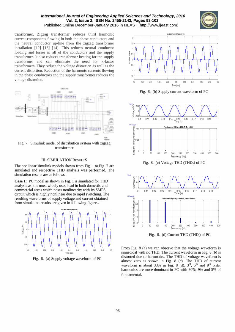
G. Distribution System With Zigzag Transformer
In this paper zigzag transformer as THD mitigation technique
is proposed [8]. In Fig. 8 Zigzag transformer is connected in
network and it is supplying 3 phase loads. Fig. 8 shows
simulation model of distribution system with zigzag
International Journal of Engineering Applied Sciences and Technology, 2016 Vol. 2, Issue 2, ISSN No. 2455-2143, Pages 93-102 Published Online December-January 2016 in IJEAST (http://www.ijeast.com)
96
transformer. Zigzag transformer reduces third harmonic
current components flowing in both the phase conductors and the neutral conductor up-line from the zigzag transformer
installation [12] [13] [14]. This reduces neutral conductor
loading and losses in all of the conductors and the supply
transformer. It also reduces transformer heating for the supply
transformer and can eliminate the need for k-factor
transformers. They reduce the voltage distortion as well as the
current distortion. Reduction of the harmonic currents flowing
in the phase conductors and the supply transformer reduces the
voltage distortion.
Fig. 7. Simulink model of distribution system with zigzag
transformer
III. SIMULATION RESULTS
The nonlinear simulink models shown from Fig. 1 to Fig. 7 are simulated and respective THD analysis was performed. The simulation results are as follows
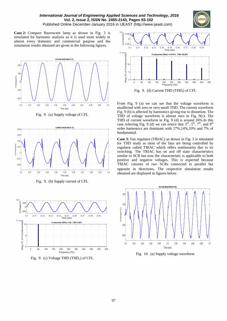
Case 1: PC model as shown in Fig. 1 is simulated for THD analysis as it is most widely used load in both domestic and commercial areas which poses nonlinearity with its SMPS circuit which is highly nonlinear due to rapid switching. The resulting waveforms of supply voltage and current obtained from simulation results are given in following figures.
Fig. 8. (a) Supply voltage waveform of PC
Fig. 8. (b) Supply current waveform of PC
Fig. 8. (c) Voltage THD (THDv) of PC
Fig. 8. (d) Current THD (THDi) of PC
From Fig. 8 (a) we can observe that the voltage waveform is sinusoidal with no THD. The current waveform in Fig. 8 (b) is distorted due to harmonics. The THD of voltage waveform is almost zero as shown in Fig. 8 (c). The THD of current waveform is about 33% in Fig. 8 (d). 3rd, 5th and 9th order harmonics are more dominant in PC with 30%, 9% and 5% of
fundamental.
International Journal of Engineering Applied Sciences and Technology, 2016 Vol. 2, Issue 2, ISSN No. 2455-2143, Pages 93-102 Published Online December-January 2016 in IJEAST (http://www.ijeast.com)
97
Case 2: Compact fluorescent lamp as shown in Fig. 2 is simulated for harmonic analysis as it is used most widely in almost every domestic and commercial purpose and the simulation results obtained are given in the following figures.
Fig. 9. (a) Supply voltage of CFL
Fig. 9. (b) Supply current of CFL
Fig. 9. (c) Voltage THD (THDv) of CFL
Fig. 9. (d) Current THD (THDi) of CFL
From Fig. 9 (a) we can see that the voltage waveform is unaffected with zero or very small THD. The current waveform Fig. 9 (b) is affected by harmonics giving rise to distortion. The THD of voltage waveform is almost zero in Fig. 9(c). The THD of current waveform in Fig. 9 (d) is around 26%.In this case referring Fig. 9 (d) we can notice that 3rd, 5th, 7th, and 9th order harmonics are dominant with 17%,14%,10% and 7% of fundamental.
Case 3: Fan regulator (TRIAC) as shown in Fig. 3 is simulated for THD study as most of the fans are being controlled by regulator called TRIAC which offers nonlinearity due to its switching. The TRIAC has on and off state characteristics similar to SCR but now the characteristic is applicable to both positive and negative voltages. This is expected because TRIAC consists of two SCRs connected in parallel but
opposite in directions. The respective simulation results obtained are displayed in figures below.
Fig. 10. (a) Supply voltage waveform

International Journal of Engineering Applied Sciences and Technology, 2016 Vol. 2, Issue 2, ISSN No. 2455-2143, Pages 93-102 Published Online December-January 2016 in IJEAST (http://www.ijeast.com)
98
Fig. 10. (b) Supply current waveform
Fig. 10. (c) Voltage THD (THDv) of fan
Fig. 10. (d) Current THD (THDi) of fan
As triac acts upon supply voltage so as to have speed control it
introduces voltage as well as current harmonics and hence both
waveforms gets distorted as shown in Fig. 10 (a) and 10 (b).
From Fig. 10(c) we can observe that voltage THD is about
73.6%. From the Fig. 10 (d) we can observe that the current THD is about 32% with 3rd, 5th and 9th order harmonics as
dominant harmonics with 27%, 14% and 5% of fundamental.
Case 4: UPS model as shown in Fig. 4 is simulated for
analyzing THD as it has nonlinearity in two stages, one in input
rectifier and other in output inverter. The respective results are
given in following figures.
Fig. 11. (a) Supply voltage waveform of UPS
Fig. 11. (b) Supply current waveform of UPS
Fig. 11. (c) Voltage THD (THDv) of UPS

International Journal of Engineering Applied Sciences and Technology, 2016 Vol. 2, Issue 2, ISSN No. 2455-2143, Pages 93-102 Published Online December-January 2016 in IJEAST (http://www.ijeast.com)
99
Fig. 11. (d) Current THD (THDi) of UPS
Fig. 11(a) and 11(b) shows voltage and current distortions.
From Fig. 11 (d) we can observe that the UPS under
consideration produced a current THD of 17.53% with 3rd, 5th
and 7th order as dominant harmonics. From Fig. 11 (d) we can notice that the current waveform contains small amount of DC
offset and small amount of even order harmonics like 2nd and
4th.
Case 5: Simulation is performed on ASD model shown in Fig.
5 for THD analysis. As ASD consists of inverter circuit it
inherently gives rise to harmonics in the system. There are
three basic types of inverters commonly employed in
adjustable AC drives: The variable voltage inverter (VVI), or
square-wave six-step voltage source inverter (VSI), receives
DC power from an adjustable voltage source and adjusts the
frequency and voltage. The current source inverter (CSI) receives DC power from an adjustable current source and
adjusts the frequency and current. The pulse width modulated
(PWM) inverter is the most commonly chosen. The simulation
results obtained are given in the following figures.
Fig. 12. (a) Supply voltage of ASD
Fig. 12. (b) Supply current of ASD
Fig. 12. (c) Voltage THD of ASD
Fig. 12. (d) Current THD of ASD
Fig. 12(a) and 12(b) shows voltage and current distortions.
From Fig. 12 (c) we can notice that ASD under simulation
produces 30.75% of voltage THD with 3rd and 5th order as
dominant harmonics with 20% and 15% of fundamental. From
Fig. 12 (d) Current THD of 5.89% is observed with 5th and 7th
order harmonics as dominant with 5% and 2.5% of
fundamental.

International Journal of Engineering Applied Sciences and Technology, 2016 Vol. 2, Issue 2, ISSN No. 2455-2143, Pages 93-102 Published Online December-January 2016 in IJEAST (http://www.ijeast.com)
100
Case 6: Simulation is performed on distribution network
model shown in Fig. 6 with six independent homes each with above mentioned loads for THD analysis and the results are
mentioned in following figures.
Fig. 13. (a) Voltage waveforms of 3 phase distribution
network
Fig. 13. (b) Current waveforms of 3 phase distribution
network
Fig. 13. (c) Voltage THD of distribution N/W
Fig. 13. (d) Current THD of distribution N/W
Fig. 13(a) and 13(b) shows voltage and current distortions.
From Fig. 13 (c) we can see that the voltage THD is about
12.96% with 2nd and 3rd harmonics as dominant with 10% and
6% of fundamental. It is seen in Fig. 13 (d) that 22.76% current
THD is recorded with 3rd order harmonics and 10% of DC offset. It is noted that recorded THD values are exceeding the
IEEE recommendations [17]. It is suggested to take required
action to limit the THD.
Case 7: Distribution model with Zigzag transformer shown in
Fig. 7 is simulated for THD variation. The Zigzag transformer
is connected in the distribution system and it is supplying two
three phase loads. The simulation results obtained are shown in following figures.
Fig. 14. (a) Voltage waveforms of distribution system with
zigzag transformer
International Journal of Engineering Applied Sciences and Technology, 2016 Vol. 2, Issue 2, ISSN No. 2455-2143, Pages 93-102 Published Online December-January 2016 in IJEAST (http://www.ijeast.com)
101
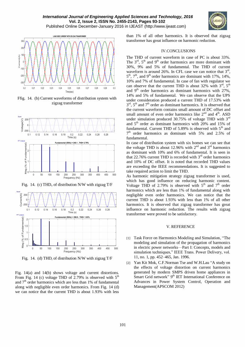
Ffig. 14. (b) Current waveforms of distribution system with
zigzag transformer
Fig. 14. (c) THDv of distribution N/W with zigzag T/F
Fig. 14. (d) THDi of distribution N/W with zigzag T/F
Fig. 14(a) and 14(b) shows voltage and current distortions.
From Fig. 14 (c) voltage THD of 2.79% is observed with 5th
and 7th order harmonics which are less than 1% of fundamental
along with negligible even order harmonics. From Fig. 14 (d)
we can notice that the current THD is about 1.93% with less
than 1% of all other harmonics. It is observed that zigzag
transformer has great influence on harmonic reduction.
IV.CONCLUSIONS
The THD of current waveform in case of PC is about 33%.
The 3rd, 5th and 9th order harmonics are more dominant with
30%, 9% and 5% of fundamental. The THD of current
waveform is around 26%. In CFL case we can notice that 3rd,
5th, 7th, and 9th order harmonics are dominant with 17%, 14%,
10% and 7% of fundamental. In case of fan with regulator we
can observe that the current THD is about 32% with 3rd, 5th
and 9th order harmonics as dominant harmonics with 27%,
14% and 5% of fundamental. We can observe that the UPS
under consideration produced a current THD of 17.53% with
3rd, 5th and 7th order as dominant harmonics. It is observed that the current waveform contains small amount of DC offset and
small amount of even order harmonics like 2nd and 4th. ASD
under simulation produced 30.75% of voltage THD with 3rd
and 5th order as dominant harmonics with 20% and 15% of
fundamental. Current THD of 5.89% is observed with 5th and
7th order harmonics as dominant with 5% and 2.5% of
fundamental.
In case of distribution system with six homes we can see that
the voltage THD is about 12.96% with 2nd and 3rd harmonics
as dominant with 10% and 6% of fundamental. It is seen in
that 22.76% current THD is recorded with 3rd order harmonics and 10% of DC offset. It is noted that recorded THD values
are exceeding the IEEE recommendations. It is suggested to
take required action to limit the THD.
As harmonic mitigation strategy zigzag transformer is used,
which has good influence on reducing harmonic content.
Voltage THD of 2.79% is observed with 5th and 7th order
harmonics which are less than 1% of fundamental along with
negligible even order harmonics. We can notice that the
current THD is about 1.93% with less than 1% of all other
harmonics. It is observed that zigzag transformer has great
influence on harmonic reduction. The results with zigzag
transformer were proved to be satisfactory.
V. REFERENCE
[1] Task Force on Harmonics Modeling and Simulation, “The
modeling and simulation of the propagation of harmonics
in electric power networks—Part I: Concepts, models and
simulation techniques,” IEEE Trans. Power Delivery, vol.
11, no. 1, pp. 452–465, Jan. 1996.
[2] Yan Kit Mok, C.F.Norman Tse and W.H.Lau “A study on
the effects of voltage distortion on current harmonics
generated by modern SMPS driven home appliances in
Smart Grid network” 9th IET International Conference on
Advances in Power System Control, Operation and
Management(APSCOM 2012)

International Journal of Engineering Applied Sciences and Technology, 2016 Vol. 2, Issue 2, ISSN No. 2455-2143, Pages 93-102 Published Online December-January 2016 in IJEAST (http://www.ijeast.com)
102
[3] J.M.Hemandez cid and J.F. Velazquez Moran “Adjustable
Speed Drive (ASD) Test Bench for Harmonic Distortion Evaluation” 2006 3rd International Conference on
Electrical and Electronics Engineering
[4] H.Sharma, W.G.Sunderman and A.Gaikwad “Harmonic
impacts of widespread use of CFL lamps on distribution
systems” , 2011, IEEE Power and Energy Society General
Meeting
[5] Stephen williamson “Reduction of the voltage and current
Harmonics Introduced by a single phase Triac AC
Controller, by means of shunt resistance” IEEE
Transaction on Industrial Electronics and control
Instrumentation 1981, volume IECI-28, Issue 4
[6] L.Băjan “Total current harmonic distortion analyses of
industrial UPS's with SCR input converter working in
redundant mode” The XIX International Conference on
Electrical Machines - ICEM 2010
[7] S.Markhalpin“Harmonic limitsin IEEE Std.519:From reco
mmendations to requirements” 2008 IEEE Power and
Energy Society General Meeting - Conversion and
Delivery of Electrical Energy in the 21st Century.
[8] Gabriel Malagon Carvajal, Gabriel Ordonez Plata, Wilson
Giraldonez Picon and Julio Cesar Chacon Velasco
“Investigatio of phase shifting transformers in distribution
systems for harmonics mitigation” Clemson University
Power Systems Conference 2014
[9] IEEE Working Group on Power System Harmonics,
“Power System Harmonics: An overview,” IEEE Trans.
on Power Apparatus and Systems, Vol. PAS-102, No. 8,
August 1983.
[10] J.K Phipps, J.P Nelson, and P.K.Sen, “Power quality and
harmonics distortion on distribution systems, “IEEE
Trans. Ind. Appl., vol.30, no.2, pp. 476-484, Mar./Apr.
1994.
[11] Int.Electrotech.Comm.61000-3-21st ed. 1995 “Limits for
Harmonic currents Emission (Equipment input current
upto and including 16A per phase)
[12] P.P. Khera “Application of zigzag transformer for
reducing harmonics in the neutral conductor of low
voltage distribution system” Conference Record of the
1990 IEEE Industry Applications Society Annual Meeting
page:1092 vol.2
[13] Azhar Ahmad, RosliOmar, Marizan Sulaiman
“Application of Zigzag transformers to Mitigatr Triplen
Harmonics in 3 phase 4 wire Electrical distribution
System” 2006, 4th student conference on research and
development.
[14] J.-G. Boudrias, "Harmonic mitigation, power factor
correction and energy Saving with proper transformer and
phase shifting Techniques, " in Conference on Electrical
and Computer Engineering., Canadian, 2004.
[15] Yang Wang, Jing Yong, Yuanyuan sun, Wilsun Xu,
Daniel Wong “Characteristics of Harmonic Distortion in Residential Distribution system” IEEE Transaction on
power delivery, 2016, Issue 99
[16] D. Salles, C. Jiang, W. Xu, W. Freitas and H. E. Mazin,
“Assessing the collective harmonic impact of modern
residential loads—part I: methodology,” IEEE Trans. on
Power Delivery, vol. 27, no.4, pp. 1937-1943, Oct. 2012.
[17] IEEE Std. 519-2014. IEEE Recommended Practice and
Requirements for Harmonic Control in Electric Power
Systems.
[18] J. Meyer, A. B. Castaneda, M. Domagk, and P. Schegner,
“Assessment of prevailing harmonic current emission in
public low voltage networks,” IEEE Trans. on Power
Delivery (early access DOI: 10.1109/TPWRD.2016.
2558187).
[19] Y.J. Wang, R.M. O'Connell and G. Brownfield,
“Modelling and prediction of distribution system voltage
distortion caused by nonlinear residential loads,” IEEE
Trans. on Power Delivery, vol. 16, no.4, pp. 744-751,
2001.
[20] José Antenor Pomilio, Sigmar Maurer Deckmann “Characterization and Compensation of Harmonics and Reactive Power of Residential and Commercial Loads” IEEE Transactions on Power delivery, vol. 22, no. 2, april 2007