public groundwater supplies in morgan and scott counties. urbana
TRANSCRIPT
ISWS/BUL-60(27)/79
BULLETIN 60-27 STATE OF ILLINOIS ILLINOIS INSTITUTE OF NATURAL RESOURCES
Public Groundwater Supplies
in Morgan and Scott Counties by DOROTHY M. WOLLER and ELLIS W. SANDERSON
ILLINOIS STATE WATER SURVEY URBANA
1979

PUBLIC GROUNDWATER SUPPLIES IN MORGAN AND SCOTT COUNTIES
by Dorothy M. Woller and Ellis W. Sanderson
Introduction This publication presents all available information on production wells used for
public water supplies in Morgan and Scott Counties. Bulletin 60, which is divided by county into separate publications, supersedes Bulletin 40 and its Supplements 1 and 2.
The definition of public water supply as contained in the Environmental Protection Act of 1970 was used to determine those water systems and wells to be included. Systems and wells described furnish water for drinking or general domestic use in: 1) incorporated municipalities; 2) unincorporated communities where 10 or more separate lots or properties are being served or are intended to be served; 3) state-owned parks and memorials; and 4) state-owned educational, charitable, or penal institutions.
This report includes separate descriptions for 7 public water supply systems furnishing water to 10 municipalities, 3 state institutions, and 1 water commission. These are preceded by brief summaries of the groundwater geology of the county and the development of groundwater sources for public use. An explanation of the format used in the descriptions is also given.
Acknowledgments. This report was prepared under the general direction of Dr. William C. Ackermann, Chief of the Illinois State Water Survey, and Richard J. Schicht, Head of the Hydrology Section. Mrs. J. L. Ivens and Mrs. P. A. Motherway edited the manuscript, Mrs. Marilyn J. Innes typed the camera-copy, John W. Brother, Jr. supervised the preparation of the illustration, and Karen L. Kunz assisted in the final preparation of the manuscript. The chemical analyses, unless otherwise stated, were made by personnel of the Water Survey Chemistry Section under the supervision of Laurel M. Henley. The analyses made by personnel of the Illinois Environmental Protection Agency were under the supervision of Ira M. Markwood. R. D. Brower and M. L. Sargent, Illinois State Geological Survey, reviewed the geological discussion. Grateful acknowledgment also is given to consulting engineers, well drillers, water superintendents, and municipal officials who have provided valuable information used in this report.
Groundwater Geology The geology of Morgan and Scott Counties is described
generally in Illinois State Geological Survey Circular 232, Groundwater Geology in Western Illinois, South Part. The following brief discussion of geologic conditions in these counties is taken largely from this publication. A more detailed definition of the geology in this portion of the state is available from the State Geological Survey located on the University of Illinois campus, Urbana.
The unconsolidated materials forming the present day land surface in Morgan and Scott Counties vary greatly in thickness and water-yielding character. Extensive deposits of sand and gravel suitable for developing large municipal, industrial, and irrigation supplies are associated with the wide Illinois River bottomlands in northwest Morgan County and along the west edge of Scott County. These deposits
range in thickness from about 50 to as much as 150 ft and are capable of yielding 500 to 1000 gpm to individual wells. Sand and gravel deposits favorable for development of small to moderate supplies also may be present in the valley of Sandy Creek, Mauvaise Terre Creek, Indian Creek, and Apple Creek. In the upland areas east of the Illinois River valley in Scott County and southern Morgan County, the unconsolidated deposits are very thin (less than 30 ft) and only occasionally contain sand and gravel deposits suitable for furnishing domestic supplies. A preglacial buried bedrock valley system (Arenzville valley) trends northwest beneath the northern part of Morgan County and contains about 50 to 150 ft of unconsolidated materials. Waterbearing sand and gravel deposits have been reported to be present in this buried valley but little information is avail-
1

able on the quantity of water that may be available. The upper bedrock units lying below the unconsolidated
deposits in Morgan and Scott Counties range in geologic age from Pennsylvanian to Silurian. Bedrock units of the Penn-sylvanian System are present in Morgan County (except in the northwest portion) and in the northeastern and southeastern areas of Scott County. These rocks consist principally of shale and range in thickness from a featheredge where eroded to about 150 ft near the southeast corner of Scott County to more than 450 ft in southeastern Morgan County. They are not considered to offer potential as a source of groundwater except for thin beds of sandstone or creviced limestone that may yield small domestic supplies.
Mississippian age rocks lie beneath the unconsolidated materials in western and central Scott County (except the southwest corner) and the Pennsylvanian rocks which are present east of the Illinois River Valley. They consist of shale, sandstone, and creviced limestone units, and have a total thickness ranging from as much as 500 ft along the east line of Morgan County to a featheredge in southwest Scott County. Erosion of the Mississippian rocks in the bedrock valley occupied by the Illinois River Valley has exposed the Devonian and Silurian rocks at the southwest corner of Scott County.
The rock formations within the Mississippian System regionally dip to the northeast at about 20 to 50 ft per mile in Scott County and east at about 10 to 40 ft per mile in Morgan County. The steeper dips in Morgan County occur toward the east. The Burlington-Keokuk Limestone and the Salem Limestone units of the Mississippian System are the principal aquifers, but their yield capability depends on the number, size and degree of interconnection of water-filled cracks and crevices within the rock that are intersected by the well bore. Quantities of water adequate for domestic and farm use usually can be obtained in Scott County from the Burlington-Keokuk Limestone aquifer where it lies at depths of less than 300 ft. The Burlington-Keokuk ranges from 210 to 245 ft thick except in southwest Scott County where it has been removed by erosion. Because of the easterly dip of the rock formations, the Burlington-Keokuk aquifer is overlain by the Warsaw Shale in most of Morgan County. The Warsaw Shale is about 80 to 110 ft thick and is nonwater-bearing. In most of Morgan County the Salem Limestone overlies the Warsaw Shale. The Salem offers potential for domestic and farm supplies although yields are marginally adequate. It lies at depths of 175 ft in the northwest part of Morgan County to about 650 ft in the southeast. Groundwater in the Salem becomes more mineralized as the unit becomes more deeply buried. In the east and the south the Salem is as much as 200 ft thick and is overlain by the St. Louis Limestone and locally by the St. Genevieve Limestone. These two units have limited potential for water supply and may contain water too mineralized for most uses.
Devonian and Silurian age limestone and dolomite occur below the Mississippian rocks and underlie the unconsolidated materials in the Illinois River bottomlands in the southwestern corner of Scott County. These rocks may have potential for development in this southwestern corner but in the rest of Scott County and in Morgan County the water is too highly mineralized for most uses.
Groundwater Development for Municipal Use Groundwater is used as a source for 7 public water supply
systems furnishing water to Alsey-Glasgow Water Commission, Ashland, Bluffs, Chapin, Jacksonville (including 3 state institutions), Lynnville, Manchester, Meredosia, Roodhouse, South Jacksonville, and Winchester. The locations of these public water supply systems are shown in figure 1.
Sand and gravel deposits in the unconsolidated materials above bedrock are tapped as sources by the Ashland, Bluffs, Jacksonville, South Jacksonville, Meredosia, and Winchester water systems. There are presently 15 supply wells and one collector well finished in sand and gravel at depths of 21 to 95 ft. The collector well can be pumped at a rate of about 6750 gpm and yields of the other wells range from about 50 to 500 gpm depending upon the type of well constructed and the permeability, thickness, and areal extent of the sand and gravel aquifer tapped by each well. Production in 1978 from the wells located in Scott County was estimated to be about 3,717,000 gpd and about 120,000 gpd from the wells in Morgan County.
Analyses of water from these wells show that the iron content ranges from 0.6 to 3.7 mg/l except at Winchester where the iron has been as high as 11.5 mg/l. The hardness ranges from about 250 to 600 mg/l. Water at Meredosia is fluoridated and chlorinated and water for Bluffs, Chapin (raw groundwater from Jacksonville), and South Jacksonville is aerated, settled, and filtered to remove iron, chlorinated, and fluoridated. Water for the South Jacksonville system (including Lynnville) is also zeolite softened and fed caustic soda for pH adjustment. The Winchester water supply is aerated, chlorinated, lime softened, recarbonated, filtered, and fluoridated. Supplemental groundwater for the Ashland and Jacksonville supplies is treated at their surface water treatment plants.
The Burlington-Keokuk Limestone aquifer in Scott County is tapped as a source of water by the Roodhouse water system which also serves Patterson (Greene County), Manchester, and the Alsey-Glasgow Water Commission. There are presently 2 supply wells 125 and 170 ft deep. They are normally pumped at rates of 450 and 600 gpm. The yield of these wells is unusual. The Burlington-Keokuk normally yields less than 30 gpm to individual wells. Production from these wells in 1978 was about 340,000 gpd. There was no public supply pumpage from the bedrock aquifers in Morgan County in 1978.
2

Figure 1. Public groundwater supply systems in Morgan and Scott Counties
Analyses of water from the Roodhouse supply system indicate that iron content is 0.1 mg/l or less and the hardness ranges from 292 to 342 mg/l. The water is chlorinated and fluoridated.
Total public water supply pumpage in Morgan and Scott Counties for 1978 was about 4,177,000 gpd. In Morgan County, 100 percent of the pumpage (120,000 gpd) was from wells tapping sand and gravel deposits. In Scott County, 92 percent (3,717,000 gpd) was from sand and gravel deposits and 8 percent (340,000 gpd) from the Burlington-Keokuk Limestone.
Format In this publication the descriptions of public water supply
systems are presented in alphabetical order by place name. At the beginning of each description the U.S. Census of
population for 1970 is given for incorporated places. For unincorporated places, the population is estimated on the
basis of the number of services or residential units and an assumed number of 3.5 persons per service.
The number of services and quantity of water distributed at each supply are given where available for the earliest and the latest reported values.
Individual production wells for each supply are described in the order of their construction. The description for each well includes the aquifer tapped, date drilled, depth, driller, legal location, elevation in feet above mean sea level, log, construction features, yield, pumping equipment, and chemical analyses.
When available, sample study logs prepared by the Illinois State Geological Survey are presented. When these are not available, drillers logs are used as reported. Commonly used drillers terms such as clay, silt, or pebbly clay generally are synonymous with the glacial tills tabulated by the State Geological Survey. Similarly, limestones or dolomites reported by drillers usually are carbonate rocks which in most of Illinois are dolomitic in composition. When stating the bedrock aquifers tapped by a well, the sample study log
3

provided by the State Geological Survey and the drillers casing record are used to determine the geohydrologic units open to the hole. If only a drillers log is available and the geohydrologic units cannot be readily determined, only the principal rock type as described by the driller is given (dolomite, sandstone, etc.).
The screen sizes given in this publication are for con
tinuous slot type screens unless stated otherwise. Slot sizes given indicate the width of the slot openings in thousandths of an inch. For example, a 20 slot screen has slot openings 0.020 in. wide and a 100 slot screen has slots 0.100 in. wide. Approximate equivalent slot openings for other types of screens are given in parentheses after the screen description.
ABBREVIATIONS USED
est estimated ft foot (feet) gpd gallons per day gpm gallons per minute hp horsepower hr hour(s) HTH high test hypochlorite ID inside diameter in inch(es) Lab laboratory me/l milliequivalents per liter mg/l milligrams per liter min minute(s) No.(s) number(s) OD outside diameter pc/l picocuries per liter R range rpm revolutions per minute T township TDH total dynamic head
4

ALSEY-GLASGOW WATER COMMISSION
Alsey-Glasgow Water Commission (est. 460), Scott County, installed a public water supply in 1974. Finished water for this supply is obtained from the city of Roodhouse (see Roodhouse). In 1976 there were 163 services; the average daily pumpage in 1977 was about 15,000 gpd.
ASHLAND
The village of Ashland (1128) installed a public water supply in 1936. Although this village is in Cass County, there are 3 wells (Nos. 1, 2, and 3) available for emergency use located in Morgan County. The main source of water supply since 1965 has been Little Indian Creek, from which water is pumped to an impounding reservoir. In 1950 there were 320 services, all metered; the estimated average daily groundwater pumpage was 60,000 gpd. In 1975 there were 520 services, 99 percent metered; the average and maximum daily surface water pumpages were 85,000 and 130,000 gpd, respectively. The surface water is prechlorinated, and fed alum, lime, and carbon, and then the water is clarified, lime softened, treated with sulfuric acid, fluoridated, filtered, and postchlorinated.
Prior to the construction of Well No. 1, several test wells were drilled in 1933 and 1935 by C. O. Robertson & Son, Campbellsburg, Ind. Most of the wells were located in the bottomlands of Little Indian Creek and its tributary.
Test Well No. 5 was located about 2 miles southwest of the village in the valley of Little Indian Creek, approximately 2300 ft S and 2300 ft W of the NE corner of Section 6, T16N, R8W, Morgan County. This test well was 21 ft deep, 6 in. in diameter, and had a 10-ft exposed length of No. 80 and 100 slot Cook screen. A production test was conducted by the State Water Survey on June 17-20, 1935. After pumping at a rate of 57 gpm, the drawdown was 9.2 ft from a nonpumping water level of 1.0 ft above land surface.
Test Well No. 6 was located about 150 ft south and 55 ft east of Test Well No. 5. This test well was 17 ft deep, 6 in. in diameter, and had a 5-ft exposed length of No. 80 and 100 slot Cook screen. On June 17-20, 1935, the well reportedly produced 30 gpm and the nonpumping water level was at land surface.
Test Well No. 8 was located 55 ft south and 80 ft east of Test Well No. 5. This test well was 18 ft deep, 6 in. in diameter, and had a 7-ft exposed length of No. 80 and 100 slot Cook screen. A production test was conducted by the State Water Survey on June 17-20, 1935. After pumping at a rate of 42.5 gpm, the drawdown was 7.2 ft from a nonpumping water level of 0.5 ft above land surface.
WELL NO. 1 (Center well), finished in sand and gravel, was constructed in June 1935 to a depth of 21 ft by C. O.
Robertson & Son, Campbellsburg, Ind., and deepened prior to 1964 to a reported depth of 24 ft. This well is available for emergency use. The well is located at the site of Test Well No. 5 about 34 ft west of the pumphouse, approximately 2300 ft S and 2300 ft W of the NE corner of Section 6, T16N, R8W, Morgan County. The land surface elevation at the well is approximately 600 ft.
A correlated drillers log of Test Well No. 5 located at the site of Well No. 1 furnished by the State Geological Survey follows:
Thickness Depth Strata (ft) (ft)
PLEISTOCENE SERIES Soil and mud 8 8 Sand and gravel, water 2 10 Clay 2 12 Sand and gravel, clean, water 9 21
The well was cased with 36-in. OD pipe from 5 ft above natural land surface to a depth of 13 ft and an 18-in. inner pipe from 4 ft below natural land surface to a depth of 12 ft followed by 9 ft (8.2 ft exposed) of 18-in. Cook wire-wound screen having 3/l6-in. slot openings. The annulus between the casings and between the bore hole and casing-screen assembly was filled with selected gravel from 4.3 to 21 ft. After deepening, the well was reported to be cased with 36-in. outer pipe from 9.5 ft above natural land surface to a depth of 13 ft and an 18-in. inner pipe from 4 ft below natural land surface to a depth of 12 ft followed by 12 ft of screen. The annulus between the 36- and 18-in. casings and between the bore hole and the casing-screen assembly is filled with gravel. The outer casing is surrounded by a 5.5-ft high earth berm.
A production test was conducted by the State Water Survey on October 17, 1935. After 8 hr of pumping at rates of 117 to 88 gpm, the drawdown was 10.8 ft from a nonpumping water level of 2.0 ft below land surface.
In 1951, the well was surged and cleaned with Calgon. Nonpumping water levels were reported to be 12.8 ft on
December 2, 1953, and 12.18 ft on March 24, 1954. Well Nos. 1,2, and 3 are connected by a common suction
header, and the water is pumped by a Deming horizontal centrifugal pump rated at 92 gpm, and powered by a 10-hp 1800 rpm U. S. electric motor.
5

A partial analysis of a sample (Lab. No. 76839) collected October 17, 1935, showed the water to have a hardness of 540 mg/l, total dissolved minerals of 586 mg/l, and an iron content of 0.7 mg/l.
WELL NO. 2 (North well), finished in sand and gravel, was completed in 1937 to a depth of 21 ft by C. O. Robertson & Son, Campbellsburg, Ind. This well is available for emergency use. The well is located about 84 ft north and 15 ft west of the pumphouse, approximately 2200 ft S and 2280 ft W of the NE corner of Section 6, T16N, R8W, Morgan County. The land surface elevation at the well is approximately 600 ft.
The well is cased with 36-in. OD pipe from 5 ft above natural land surface to a depth of 13 ft and an 18-in. inner pipe from 4 ft below natural land surface to a depth of 12 ft followed by 9 ft (8.2 ft exposed) of 18-in. Cook wire-wound screen having 3/l6-in. slot openings. The annulus between the casings and between the bore hole and the casing-screen assembly is filled with selected gravel from 4.3 to 21 ft. The outer casing was extended 2 ft above maximum flood level and surrounded by a 5.5-ft high earth berm.
In 1951, the well was surged and cleaned with Calgon. Nonpumping water levels were reported to be 16.8 ft
on December 2, 1953, and 12.65 ft on March 24, 1954. The pumping equipment presently installed is described
under Well No. 1. Two test holes were constructed in June 1954 to depths
of 80 and 56 ft by the J. P. Miller Artesian Well Co., Brook-field. The holes were located in the SW quarter of the SW quarter of the NE quarter of Section 6, T16N, R8W, Morgan County.
WELL NO. 3 (South well), finished in sand and gravel, was completed in 1937 to a depth of 21 ft by C. O. Robertson & Son, Campbellsburg, Ind. This well is available for emergency use. The well is located about 70 ft south and
84 ft west of the pumphouse, approximately 2380 ft S and 2350 ft W of the NE corner of Section 6, T16N, R8W, Morgan County. The land surface elevation at the well is approximately 600 ft.
The well is cased with 36-in. OD pipe from 5 ft above natural land surface to a depth of 13 ft and an 18-in. inner pipe from 4 ft below natural land surface to a depth of 12 ft followed by 9 ft (8.2 ft exposed) of 18-in. Cook wire-wound screen having 3/l6-in. slot openings. The annulus between the casings and between the bore hole and the casing-screen assembly is filled with selected gravel from 4.3 to 21 ft. The outer casing was extended 2 ft above maximum flood level and surrounded by a 5.5-ft high earth berm.
In 1951, the well was surged and cleaned with Calgon.
Nonpumping water levels were reported to be 12.0 ft on December 2, 1953, and 11.66 ft on March 24, 1954.
A production test with one observation well was conducted by the State Water Survey on July 16, 1954. After 8.4 hr of pumping at a rate of about 55 gpm, the drawdown was 6.35 ft from a nonpumping water level of 13.81 ft.
The pumping equipment presently installed is described under Well No. 1.
WELL NO. 4, finished in sand and gravel, was completed in 1962 to a depth of 27 ft by J. D. Rimby, Roodhouse. This well was abandoned and sealed prior to 1977. The well was located about 635 ft south of the pumphouse, approximately 2935 ft S and 2265 ft W of the NE corner of Section 6, T16N, R8W, Morgan County. The land surface elevation at the well is approximately 600 ft.
The well was cased with 36-in. concrete tile from 0.7 ft above the floor of a 4-ft deep pit to a depth of 27 ft. A concrete shell was poured around the 36-in. casing from 0 to 16 ft. The pit was reported to be 3 ft above maximum flood level.
BLUFFS
The village of Bluffs (866), Scott County, installed a public water supply in 1936. One Well (No. 3) is in use and another well (No. 2) is used for bulk sales to farmers and as an emergency source of supply for the village. In 1949, the estimated average and maximum daily pumpages were 40,000 and 50,000 gpd, respectively. In 1976 there were 363 services, all metered; the average and maximum daily pumpages were 82,000 and 110,000 gpd, respectively. The water is aerated to oxidize iron, chlorinated, fluoridated, and filtered.
WELL NO. 1, finished in sand and gravel, was completed in January 1936 to a depth of 58 ft by the Thorpe Concrete Well Co., Alton. This well was abandoned about 1948 and sealed about 1964. The well was located in the filter house near the western limits of the village and north of the Wabash RR, approximately 40 ft S and 800 ft W of the NE corner of Section 16, T15N, R13W, Scott County. The land surface elevation at the well is approximately 460 ft.
A sample study log of Well No. 1 furnished by the State Geological Survey follows:
6

Thickness Depth Strata (ft) (ft)
PLEISTOCENE SERIES Silt and sand 28 28 Sand, silty 7 35 Sand, medium to granular 23 58 "Hardpan" 0.6 58.6
A 54-in. diameter hole was drilled to a depth of 35 ft and finished 49 in. in diameter from 35 to 58 ft. The well was cased with 26-in. ID by 36-in. OD solid concrete pipe from 4 ft above land surface to a depth of 14 ft. A porous concrete casing of the same size extended from 14 to 58 ft and a 1-ft thick concrete plug was placed at the bottom. A 54-in. steel casing surrounded the gravel envelope around the concrete casing between the depths of 5 and 35 ft. The annulus between the 54-in. bore hole and steel pipe and the solid and porous concrete casing was filled with clay from 0 to 14 ft and with gravel from 14 to 35 ft, and the annulus between the 49-in. bore hole and porous casing was filled with gravel from 35 to 59 ft.
A production test was conducted by the State Water Survey on January 21, 1936. After 3.8 hr of pumping at rates ranging from 173 to 168 gpm, the drawdown was 7.1 ft from a nonpumping water level of 15.5 ft below land surface. Prior to the test, operation of the pumps in the Wabash RR wells, located 60 ft southwest and 75 ft south, lowered the water level in this well 2.9 ft in 30 min.
A production test was conducted by the State Water Survey on February 13, 1936. After 8 hr of pumping at rates of 167 to 178 gpm, the drawdown was 9.8 ft from a nonpumping water level of 11.9 ft below land surface. During this test, the Wabash RR wells were pumping intermittently.
On February 13, 1940, the well reportedly produced 60 gpm for 20 min with a drawdown of 17.5 ft from a nonpumping water level of 21.0 ft below land surface.
In February 1946, after pumping at a rate of 62 gpm, the drawdown was 40 ft from a nonpumping water level of 18 ft.
A mineral analysis of a sample (Lab. No. 113729) collected March 12, 1948, showed the water to have a hardness of 578 mg/l, total dissolved minerals of 788 mg/l, and an iron content of 1.8 mg/l.
WELL NO. 2, finished in sand and gravel, was completed in September 1947 to a depth of 57 ft by R. R. Long, Jacksonville. This well is used for bulk sales to farmers and as an emergency source of supply for the village. The well is located about 125 ft west-northwest of the filter house, approximately 20 ft S and 900 ft W of the NE corner of Section 16, T15N, R13W, Scott County. The land surface elevation at the well is approximately 460 ft.
An 8-in. diameter hole was drilled to a depth of 57 ft. The well is cased with 8-in. wrought iron pipe from 1 ft above the pumphouse floor to a depth of 45 ft followed by 12 ft of 8-in. No. 16 slot Johnson screen.
Upon completion, the well reportedly produced 90 gpm for 7 hr with a drawdown of 7.2 ft from a nonpumping water level of 17.0 ft below the top of the casing.
Before being placed in service, the well reportedly produced 220 gpm for 24 hr with a drawdown of 16.0 ft from a nonpumping water level of 17.2 ft below the pump base.
In 1960, this well was acidized with HTH by the Layne-Western Co., Kirkwood, Mo.
The pumping equipment presently installed consists of a 5-hp 1735 rpm General Electric motor (No. SD5653), a 6-in., 5-stage Fairbanks-Morse Pomona vertical turbine pump (No. SH2942) set at 40 ft, rated at 220 gpm at about 70 ft head, and has 40 ft of 4-in. column pipe. A 10-ft section of 4-in. suction pipe is attached to the pump intake. The well is equipped with 47 ft of airline.
A mineral analysis made by the Illinois Environmental Protection Agency (Lab. No. A12289) of a sample collected December 7, 1976, after pumping for 1 hr at 50 gpm, showed the water to have a hardness of 457 mg/l, total dissolved minerals of 490 mg/l, and an iron content of 3.70 mg/l.
Prior to the construction of Well No. 3, two test holes, located in the NE quarter of Section 16, T15N, R13W, Scott County, were drilled in July 1958 by the Layne-Western Co., Kirkwood, Mo., to depths of 58.5 and 56.3 ft.
WELL NO. 3, finished in sand and gravel, was completed in October 1958 to a depth of 59.4 ft by the Layne-Western Co., Kirkwood, Mo. The well is located about 50 ft east of the pump station, approximately 5 ft S and 755 ft W of the NE corner of Section 16, T15N, R13W, Scott County. The land surface elevation at the well is approximately 460 ft.
A drillers log of Well No. 3 follows:
Thickness Depth Strata (ft) (ft)
Clay f i l l 2 2 Black soil 3 5 Yellow clay 19 24 Gray clay 4 28 Medium to fine sand 17 45 Medium to coarse sand, loose 11 56 Clay and fine sand 3.4 59.4
A 34-in. diameter hole was drilled to a depth of 59.4 ft. The well is cased with 26-in. outer pipe from land surface to a depth of 25 ft and 12-in. inner pipe from 2.5 ft above land surface to a depth of 49.5 ft and equipped with 15 ft of 12-in. No. 5 (0.105 in.) Layne stainless steel shutter screen. The annulus between the bore hole and 26-in. casing is filled with concrete grout from 0 to 25 ft, and the annulus between the 26- and 12-in. casings and between the bore hole and 12-in. casing-screen assembly is filled with gravel from 0 to 59.4 ft.
A production test using two observation wells was conducted on October 9, 1958, by representatives of the driller, the village, and the State Water Survey. After 8 hr of pumping at rates ranging from 154 to 252 gpm, the final draw-
7

down was 12.22 ft from a nonpumping water level of 18.83 ft below land surface. Thirty-one min after pumping was stopped, the water level had recovered to 21.42 ft.
In 1972, this well was acidized by the Layne-Western Co. The production rate was then reported to be 250 gpm with 10 ft of drawdown.
The pumping equipment presently installed is a Layne vertical turbine pump set at 40 ft, rated at 250 gpm, and powered by a 5-hp U. S. electric motor.
The following mineral analysis made by the Illinois Environmental Protection Agency (Lab. No. B15522) is for a water sample from the well collected October 2, 1978, after 2 hr of pumping at 250 gpm.
W E L L N O . 3 , L A B O R A T O R Y N O . B 1 5 5 2 2
mg/l me/l mg/l me/l I r o n Fe 1.66 S i l i ca S i O 2 15 Manganese Mn 0 .27 F l u o r i d e F 0 . 3 0 . 0 2 A m m o n i u m N H 4 0 . 3 0 .02 B o r o n B 0 .3 S o d i u m N a 2 1 0 .91 N i t r a t e N O 3 0 .4 0 . 0 1 Potass ium K 4 . 0 0 . 1 0 C h l o r i d e Cl 14 0 . 4 0 C a l c i u m C a 1 1 9 5 . 9 4 S u l f a t e S O 4 1 6 5 3 . 4 3 Magnes ium M g 5 7 4 . 6 9 A l k a l i n i t y ( a s C a C O 3 ) 3 7 5 7 . 5 0
A rsen ic A s < 0 . 0 0 1 Hardness (as C a C O 3 ) 5 2 4 1 0 . 4 8 B a r i u m Ba 0 .1 Copper Cu 0 .01
T o t a l d isso lved C a d m i u m Cd 0 . 0 0
m ine ra l s 611 C h r o m i u m C r 0 . 0 0 Lead Pb 0 . 0 0 0 M e r c u r y H g < 0 . 0 0 0 0 2 N i cke l N i 0 .0 S e l e n i u m S e < 0 . 0 0 1 Si lver A g 0 . 0 0 C y a n i d e C N 0 . 0 0 Z i n c Zn 0 . 0 0 pH (as r e c ' d ) 7.6
CHAPIN
The village of Chapin (552), Morgan County, installed a public water supply in 1955. Water for this supply is obtained from the Jacksonville raw water transmission main supplied by a well located in the Illinois River bottomlands (see Jacksonville). In 1956 there were 185 services, all metered; the average daily consumption was 10,500 gpd. In 1976-there were 229 services, all metered; the average and maximum daily consumptions were 40,000 and 50,000 gpd, respectively. The water is aerated, settled, chlorinated, filtered, and fluoridated.
In an attempt to construct a groundwater supply for the village, a test well was drilled in June 1946 to a depth of 126 ft by R. R. Long, Jacksonville. It was located 40 ft west of Congress St. and 230 ft south of French St., approximately 230 ft S and 2150 ft E of the NW corner of Section 11, T15N, R12W, Morgan County.
A correlated drillers log of the test well furnished by the State Geological Survey follows:
Thickness Depth Strata (ft) (ft)
P L E I S T O C E N E S E R I E S So i l and c lay 16 16 Sand and gravel 12 28 Shale (c lay?) 1 5 4 3 Clay 10 53 Shale (c lay?) 8 61
Thickness Depth Strata (continued) (ft) (ft)
P E N N S Y L V A N I A N S Y S T E M L i m e shel ls , w a t e r 4 65 Shale 2 0 8 5 L i m e , shel ls , w a t e r 4 89 Shale a n d sandy shel ls 2 8 1 1 7 No reco rd 9 1 2 6
An 8-in. diameter hole was drilled to a depth of 126 ft. The test well was cased with 8-in. ID pipe from 1 ft above land surface to a depth of 64.7 ft and 6-in. ID pipe from 61.2 ft to a depth of 126 ft (slotted between 61 and 65 ft and between 85 and 89 ft).
A production test was conducted on June 25, 1946, by representatives of the driller, the village, and the State Water Survey. After 2.7 hr of pumping at rates of 27 to 7 gpm, the drawdown was 30.5 ft from a nonpumping water level of 15.5 ft below land surface. Pumping was continued for 3.1 hr at rates of 15.8 to 11.4 gpm with a final drawdown of 62.5 ft. Eighteen min after pumping was stopped, the water level had recovered to 45.0 ft.
In 1950, three test holes were drilled to depths of 47, 33, and 22 ft. One of the holes was located within the village and the other two were located 3 miles south-southwest of the village in Scott County.
8

ILLINOIS SCHOOL FOR THE VISUALLY IMPAIRED - JACKSONVILLE
Illinois School for the Visually Impaired, located on the east side of Jacksonville in Morgan County, installed a public water supply in 1921. Finished water for this supply is obtained from the city of Jacksonville (see Jacksonville). In 1956 with a population of 360, the average daily consumption was 40,000 gpd. In 1977 the population was 314; the average and maximum daily consumptions in 1975 were 16,099 and 22,730 gpd, respectively.
ILLINOIS SCHOOL FOR THE DEAF - JACKSONVILLE
Illinois School for the Deaf, located on the northwest edge of Jacksonville in Morgan County, installed a public water supply in 1915. Finished water for this supply is obtained from the city of Jacksonville (see Jacksonville). In 1956 with a population of 480, the average daily consumption was 19,050 gpd. In 1977 with a population of 759, the average daily consumption was 42,300 (summer) and 66,740 (winter) gpd.
JACKSONVILLE
The city of Jacksonville (20,553) installed a public water supply in 1871. Although this city is located in Morgan County, the Ranney collector well is located in Scott County. Water is obtained from a 237-million gallon impoundment reservoir (Lake Mauvaise Terre) constructed in 1921, supplemented by flow from a 2115-million gallon impoundment reservoir (Lake Jacksonville) constructed in 1940, and a Ranney collector well constructed in 1955. This supply is also cross connected with the village of South Jacksonville. Water from this system also supplies the village of Chapin, Illinois School for the Visually Impaired, Illinois School for the Deaf, and the Jacksonville Mental Health and Development Center. In 1950 there were 3700 services, all metered; the average daily pumpage was 2,800,000 gpd. In 1978 there were 6661 services, all metered (including satellite supplies); the total average and maximum daily pumpages were 3,199,663 (3,059,517 gpd from Ranney collector well) and 4,400,000 gpd, respectively. The water is chlorinated; fed potassium permanganate, alum, lime, sodium hexameta-phosphate; settled; recarbonated; fluoridated; and filtered.
From 1871 until about 1921, water for the city was obtained from Morgan Lake, which is presently used for recreation purposes. At times part of the public water supply has been obtained from wells. The city purchased a well from the Gas and Oil Syndicate, which had been drilled in 1885 to a depth of 1600 ft. The well, located near the Wabash RR in Jacksonville, was deepened to a reported depth of 2343 ft about 1886. This well was abandoned in
1895 because of insufficient production and was sold to J. Capps and Son. Three wells were drilled between 1888 and 1895 on the pumping station grounds in the south part of the city to depths of 3110, 3100, and 3118 ft, respectively. These wells were abandoned in 1914. Sometime after 1895, a small dam was constructed across Mauvaise Terre Creek and creek water was run into the system for emergency use for about 5 years. In 1905, a private water company was contracted to furnish water to the city. The company used 14 wells, ranging in depth from 68 to 70 ft, located in the Illinois River bottoms near Bluffs about 19 miles west of Jacksonville. From October 1907 to about April 1909, water was pumped from the 14 wells to the city reservoir, but frequent problems were encountered and all of the wells were disconnected from the system in 1912. Five wells, known as the Widenham-Daub wells, were drilled from 1910 to 1912 to depths ranging from 64.5 to 77 ft on the bank of Mauvaise Terre Creek near the northern limits of the city. These wells furnished part of the public supply from 1913 to 1921, and some nearby test wells were also used when additional water was needed. In 1923 and 1931, three of the Widenham-Daub wells were used during an emergency. The five Widenham-Daub wells and the test wells were abandoned in 1940 until 1954 when 2 of the wells were used in an emergency. From 1917 to 1921, the supply was also supplemented with water from Ashelby Pond and a drainage ditch.
A detailed discussion of these early supply wells is included
9

in Bulletin 21 and the Illinois State Water Survey basic record files.
COLLECTOR WELL NO. 1, finished in sand and gravel, was constructed in January 1955 by The Ranney Co., Westerville, Ohio. Water can be discharged to either Lake Mauvaise Terre or directly into the city water plant. The well is located about 23 miles west of Jacksonville on the bank of the Illinois River near Naples, approximately 1100 ft S and 2250 ft W of the NE corner of Section 12, T15N, R14W, Scott County. The land surface elevation at the well is 447.9 ft.
A drillers log of Collector Well No. 1 follows:
Thickness Depth Strata (ft) (ft)
F ine s a n d y s i l t 2 5 2 5 M e d i u m sand , t races gravel 9 34 15 p e r c e n t pea grave l , 5 percen t m e d i u m
gravel m e d i u m sand 1 6 5 0 10 p e r c e n t pea g rave l , m e d i u m s a n d , c lay bal ls 2 52 M e d i u m sand , t races gravel 8 60 10 pe rcen t m e d i u m grave l , g ray sand 9 69 20 pe rcen t med ium-coa rse g rave l , m e d i u m sand 11 80 15 p e r c e n t med ium-coa rse grave) , m e d i u m sand 9 89 4 0 p e r c e n t med ium-coa rse g rave l , m e d i u m sand ,
b o u l d e r s 6 95
The reinforced concrete caisson (13 ft ID by 16 ft OD) was constructed from about 8 ft below land surface to a depth of 93 ft and a concrete plug was poured in the bottom. Seven 8-in. diameter perforated steel horizontal laterals (with 3/8- by 1½-in. slot openings) were hydraulically projected at a depth of 82.4 ft below the top of the caisson. The total length of the 7 laterals is 1056 ft with the individual lengths running from 136 to 176 ft.
On January 26, 1955, the nonpumping water level was reported to be 22 ft below the top of the caisson.
A production test with one observation well was conducted on September 1-11, 1955, by representatives of
the driller, the State Water Survey, and Casler & Stapleton, Consulting Engineers. After 240 hr of pumping at a rate of 5000 gpm, the drawdown was 25.27 ft from a nonpumping water level of 19.81 ft below the top of the caisson.
The pumping equipment presently installed consists of 3 pumps as follows: 2 are Byron Jackson turbines set at 82 ft below land surface, each rated at 2700 gpm at about 330 ft TDH, and powered by a 300-hp General Electric motor, and the third pump is a Byron Jackson turbine set at 82 ft below land surface, rated at 1350 gpm at about 330 ft TDH, and powered by a 150-hp General Electric motor.
The following mineral analysis made by the Illinois Environmental Protection Agency (Lab. No. A110015) is for a water sample from the well collected December 9, 1974, after pumping continuously at 1600 gpm.
C O L L E C T O R W E L L N O . 1 , L A B O R A T O R Y N O . A 1 1 0 0 1 5
mg/l me/l mg/l me/l I r on Fe 2 .8 Si l ica S i O 2 16 Manganese Mn 0 .3 F l u o r i d e F 0 . 3 0 .02 A m m o n i u m N H 4 0 .4 0 .02 B o r o n B 0 .2 S o d i u m N a 1 2 0 .52 N i t r a t e N O 3 7 .0 0 .11 Po tass ium K 1.8 0 .05 C h l o r i d e Cl 23 0 .65 C a l c i u m Ca 68 3 .39 Su l f a t e S O 4 50 1.04 M a g n e s i u m M g 2 8 2 .30 A l k a l i n i t y ( a s C a C O 3 ) 2 2 0 4 . 4 0
Arsen ic As 0 .01 Hardness (as C a C O 3 ) 2 9 0 5.80
B a r i u m Ba 0 .0 T o t a l d isso lved Copper C u 0 . 0 0 minera ls 3 6 0 C a d m i u m C d 0 . 0 0 C h r o m i u m C r 0 . 0 0 Lead Pb 0 . 0 0 M e r c u r y Hg 0 . 0 0 0 0 pH (as rec 'd ) 7.7 N i cke l N i 0 .0 R a d i o a c t i v i t y S e l e n i u m Se 0 . 0 0 A l p h a pc/ l 0 .4 Si lver Ag 0 . 0 0 ± d e v i a t i o n 1.4 C y a n i d e CN 0 . 0 0 0 Beta pc/ l 1.7 Z i n c Zn 0 .0 ± d e v i a t i o n 1.8
JACKSONVILLE MENTAL HEALTH AND DEVELOPMENT CENTER
Jacksonville Mental Health and Development Center, located on the south side of Jacksonville in Morgan County, installed a public water supply in 1851. Finished water for this supply is obtained from the city of Jacksonville (see Jacksonville). In 1956 with a population of 4800, the average daily consumption was 410,000 gpd. In 1976 with a population of 300, the average and maximum daily consumptions were 232,000 and 300,000 gpd, respectively.
10

LYNNVILLE
The village of Lynnville (125), Morgan County, installed a public water supply in 1970. Finished water for this supply is obtained from the village of South Jacksonville (see South Jacksonville). In 1976 there were 82 services, all metered; the average and maximum daily consumptions in 1974 were 3500 and 7500 gpd, respectively.
MANCHESTER
The village of Manchester (335), Scott County, installed a public water supply in 1963. Finished water for this supply is obtained from the city of Roodhouse (see Roodhouse). In 1964 there were 115 services, all metered. In 1972 there were 127 services, all metered; the average daily pumpage in 1977 was about 21,000 gpd.
Prior to receiving water from Roodhouse, in 1959 and 1960 the Layne-Western Co., Kirkwood, Mo., constructed 34 test holes ranging from 25 to 73 ft deep.
Test Well No. 1, finished in sand and gravel, was constructed in April 1960 to a depth of 29 ft by the Layne-Western Co., Kirkwood, Mo. The test well was located approximately 2200 ft N and 1700 ft E of the SW corner of Section 28, T13N, R11W, Scott County. An 18-in. diameter hole was drilled to a depth of 29 ft. The test well was cased with 8-in. pipe from 1 ft above land surface to a depth of 23 ft followed by 6 ft of 8-in. slotted pipe and gravel packed. A production test with four observation wells was conducted on April 13, 1960, by representatives of the driller, the State Water Survey, and the Caldwell-Rhoads Co., Consulting Engineers. After 7.5 hr of pumping at rates ranging from 9.4 to 10.5 gpm, the final drawdown was 18.80 ft from a nonpumping water level of 3.49 ft below the top of the casing. Twenty-eight min after pumping was stopped, the water level had recovered to 9.48 ft. A second production test was conducted on April 15, 1977, by representatives of the driller, the State Water Survey, and the Caldwell Engineering Co. After 10 min of pumping at rates ranging from 5.3 to 3.5 gpm, the drawdown was 8.68 ft from a nonpumping water level of 3.30 ft below land surface. Thirty min after pumping was stopped, the water level had recovered to 3.90 ft. A partial analysis of a sample (Lab. No. 153187) collected September 9, 1960, showed the water to have a hardness of 500 mg/l, total dissolved minerals of 601 mg/l, and an iron content of 2.0 mg/l.
Test Well No. 2, finished in sand and gravel, was constructed in August 1960 to a depth of 27 ft by the Layne-Western Co., Kirkwood, Mo. The test well was located approximately 2340 ft N and 1560 ft E of the SW corner of Section 28, T13N, R11W, Scott County. A 20-in. diameter hole was drilled to a depth of 27 ft. The test well was cased
with 8-in. pipe from 1 ft above land surface to a depth of 21 ft followed by 6 ft of 8-in. slotted pipe and gravel packed. A production test was conducted on March 17, 1977, by representatives of the driller, the State Water Survey, and the Caldwell Engineering Co. After 1 hr of pumping at rates of 6.5 to 4.6 gpm, the drawdown was 7.16 ft from a nonpumping water level of 2.07 ft below land surface. Thirty min after pumping was stopped, the water level had recovered to 5.36 ft. A partial analysis of a sample (Lab. No. 204558) collected March 17, 1977, after pumping for 45 min at 5 gpm, showed the water to have a hardness of 588 mg/l, total dissolved minerals of 715 mg/l, and an iron content of 0.9 mg/l.
Test Well No. 3, finished in sand and gravel, was constructed in September 1960 to a depth of 33.5 ft by the Layne-Western Co., Kirkwood, Mo. The test well was located approximately 2290 ft N and 1920 ft E of the SW corner of Section 28, T13N, R11W, Scott County.
A drillers log of Test Well No. 3 follows:
Thickness Depth Strata (ft) (ft)
Top soil 2 2 Brown clay 8 10 Soft gray clay 11 21 Hard gray clay 2.5 23.5 Dirty, medium sand (water bearing) 7.5 31 Coarse clean sand and gravel (water bearing) 2.5 33.5 Hard gray clay 2.5 36
A 20-in. diameter hole was drilled to a depth of 34.5 ft. The test well was cased with 8-in. pipe from 1 ft above land surface to a depth of 23.5 ft followed by 10 ft of 8-in. slotted pipe and gravel packed. A production test with two observation wells was conducted on September 8-9, 1960, by representatives of the driller, the State Water Survey, and the Caldwell-Rhoads Co. After 24 hr of pumping at rates ranging from 15 to 9.7 gpm, the final drawdown was 16.72 ft from a nonpumping water level of 8.63 ft below land surface. A second production test was conducted on April 15, 1977, by representatives of the driller, the State Water Survey, and the Caldwell Engineering Co. After 1 hr of pumping at rates ranging from 3.9 to 3.5 gpm, the drawdown was 2.70
11

ft from a nonpumping water level of 3.58 ft below land surface. Thirty min after pumping was stopped, the water level had recovered to 5.18 ft.
Analyses of the production tests made in 1960 indicated
that the long-term yield of the 3-well system would be about 15 gpm (21,600 gpd). Results of the 1977 production tests confirmed that 15 gpm represented a maximum yield for the 3-well system.
MEREDOSIA
The village of Meredosia (1178), Morgan County, installed a public water supply in 1950. Three wells (Nos. 2, 3, and 4) are in use. In 1950 there were 237 services, all metered. In 1976 there were 408 services, all metered; the average and maximum daily pumpages were 120,000 and 200,000 gpd, respectively. The water is fluoridated and chlorinated.
WELL NO. 1, finished in sand and gravel, was constructed in April 1950 to a depth of 40 ft by R. R. Long, Jacksonville, deepened in August 1954 to a reported depth of 60 ft by J. P. Johnson, Plymouth, and deepened again in 1961 to a reported depth of 76 ft below the top of the pump pedestal by the J. B. Bushnell Well Drilling Co., Plymouth. This well was abandoned and sealed in 1975 because it was pumping sand and had severe iron bacteria growth. The well was located near the east edge of the village just north of Illinois Route 104, approximately 900 ft S and 3000 ft W of the NE corner of Section 22, T16N, R13W, Morgan County. The land surface elevation at the well is approximately 450 ft.
A drillers log of Well No. 1 follows:
Thickness Depth Strata (ft) (ft)
Originally, the well was cased with 8-in. steel pipe from 1.5 ft above the pump station floor to a depth of 30.5 ft followed by 9.5 ft (11 ft overall length) of No. 16 slot Johnson Everdur screen. After the 1961 deepening, the well was reported to be cased with 8-in. pipe from 0.4 in. below the pump pedestal to a depth of 56 ft followed by 20 ft of screen. The screened section consisted of 10 ft of No. 16 slot followed by 10 ft of No. 20 slot.
Upon completion of the well in 1950, a production test was conducted on April 26, 1950, by representatives of the driller, the village, the State Water Survey, and Casler & Stapleton, Consulting Engineers. After 4.1 hr of pumping at rates ranging from 50 to 71 gpm, the drawdown was 6.8 ft from a nonpumping water level of 19.4 ft below land surface. Full recovery was observed after pumping had been stopped for 1.3 hr.
This well was acidized in 1970 by J. P. Johnson.
A mineral analysis made by the Illinois Environmental Protection Agency (Lab. No. B136292) of a sample collected April 23, 1975, after pumping for 30 min at 60 gpm, showed the water to have a hardness of 292 mg/l, total dissolved minerals of 382 mg/l, and an iron content of 0.2 mg/l.
WELL NO. 2 (locally referred to as Well No. 3), finished in sand and gravel, was constructed in April 1950 to a depth of 40 ft by R. R. Long, Jacksonville, and deepened in 1961 to a reported depth of 60 ft by J. P. Johnson, Plymouth. The well is located about 112 ft northeast of Well No. 1, approximately 875 ft S and 2900 ft W of the NE corner of Section 22, T16N, R13W, Morgan County. The land surface elevation at the well is approximately 450 ft.
A sample study summary log of Well No. 2 furnished by the State Geological Survey follows:
Thickness Depth Strata (ft) (ft)
PLEISTOCENE SERIES Sand, light brown, f ine, rounded,
well sorted 25 25 Sand, light brown, fine to medium, clean 10 35 Sand, l ight brown, fine to very coarse, clean 5 40 Interval not studied 20 60
Originally, the well was cased with 8-in. steel pipe from 1.5 ft above the pumphouse floor to a depth of 30 ft followed by 10 ft (11 ft overall length) of No. 16 slot Johnson Everdur screen. After deepening, the well was reported to be cased with 8-in. pipe from 0.1 ft above the pump station floor to a depth of 40 ft followed by 20 ft of screen. The screened section consists of 10 ft of No. 16 slot followed by 10 ft of No. 20 slot.
A production test with one observation well was conducted on May 1, 1950, by representatives of the driller, the village, the State Water Survey, and Casler & Stapleton, Consulting Engineers. After 5.4 hr of pumping at rates ranging from 125 to 119 gpm, the drawdown was 10.1 ft from a nonpumping water level of 14.8 ft below land surface. Nine min after pumping was stopped, full recovery was observed.
A production test was conducted by the State Water Survey on February 5, 1973. After 2 hr of pumping at a rate of 68 gpm, the final drawdown was 5.04 ft from a nonpumping water level of 18.38 ft below land surface. Ten
12
Sand 30 30 Sand (coarse) 10 40 Sand and gravel 36 76

min after pumping was stopped, the water level had recovered to 18.39 ft.
The pumping equipment presently installed is a Jacuzzi submersible pump rated at 70 gpm, and powered by a 5-hp Franklin electric motor.
A mineral analysis made by the Illinois Environmental Protection Agency (Lab. No. A18548) of a sample collected March 14, 1977, showed the water to have a hardness of 305 mg/l, total dissolved minerals of 380 mg/l, and an iron content of 0.65 mg/l.
WELL NO. 3 (locally referred to as Well No. 2), finished in sand and gravel, was completed in September 1973 to a depth of 84 ft by the Calhoun Well Drilling Co., Batchtown. The well is located about 120 ft north-northeast of the plant building, approximately 800 ft S and 2950 ft W of the NE corner of Section 22, T16N, R13W, Morgan County. The land surface elevation at the well is approximately 450 ft.
A drillers log of Well No. 3 follows:
Thickness Depth Strata (ft) (ft)
Fine sand 62 62 F ine sand w i t h s o m e coarse sand 2.5 6 4 . 5 Coarse sand w i t h some f i ne sand 19.5 84
A 12-in. diameter hole was drilled to a depth of 20 ft and finished 8 in. in diameter from 20 to 84 ft. The well is equipped with a Merrill pitless adapter from 2 ft above land surface to a depth of 5 ft and cased with 8-in. steel pipe to a depth of 70 ft followed by 14 ft of 8-in. No. 25 slot Johnson stainless steel screen. The annulus between the bore hole and casing is filled with cement grout from 5 ft below land surface to 20 ft.
The pumping equipment presently installed is a Reda submersible pump set at 68 ft, rated at 100 gpm, and powered by a 5-hp Reda electric motor.
A mineral analysis made by the Illinois Environmental Protection Agency (Lab. No. B19066) of a sample collected October 31, 1977, after pumping for 24 hr at 85 gpm, showed the water to have a hardness of 394 mg/l, total dis
solved minerals of 472 mg/l, and an iron content of 0.8 mg/l.
WELL NO. 4 (locally referred to as Well No. 1), finished in sand and gravel, was completed in July 1975 to a depth of 87.5 ft by the J. B. Bushnell Well Drilling Co., Plymouth. The well is located about 50 ft northeast of the plant building, approximately 850 ft S and 2950 ft W of the NE corner of Section 22, T16N, R13W, Morgan County. The land surface elevation at the well is approximately 450 ft.
A 12-in. diameter hole was drilled to a depth of 20 ft and finished 8 in. in diameter from 20 to 87.5 ft. The well is equipped with a Monitor pitless adapter from 2 ft above land surface to a depth of 5 ft and cased with 8-in. steel pipe to a depth of 73.5 ft followed by 14 ft of 8-in. No. 25 slot Johnson stainless steel screen. The annulus between the bore hole and casing is filled with cement grout from 5 ft below land surface to 20 ft.
The pumping equipment presently installed is a Jacuzzi submersible pump set at 68 ft, rated at 110 gpm, and powered by a 5-hp Franklin electric motor.
The following mineral analysis made by the Illinois Environmental Protection Agency (Lab. No. A18545) is for a water sample from the well collected March 14, 1977.
W E L L N O . 4 , L A B O R A T O R Y N O . A 1 8 5 4 5
mg/l me/l mg/l me/l I r on Fe 0 . 7 4 Si l ica S i O 2 13 Manganese Mn 0 .18 F l u o r i d e F 0 . 1 2 0 .01 A m m o n i u m N H 4 0 . 06 0 . 0 0 B o r o n B 0 .2 S o d i u m N a 1 0 0 . 4 4 N i t r a t e N O 3 1 4 . 1 0 .23 Potass ium K 1.5 0 . 0 4 C h l o r i d e Cl 22 0 .62 C a l c i u m C a 6 6 3 .29 Su l f a t e S O 4 5 0 1.04 Magnes ium M g 2 8 2 . 3 0 A l k a l i n i t y ( a s C a C O 3 ) 2 4 0 4 . 8 0
Arsen ic As 0 . 0 0 0
B a r i u m Ba 0.2 Hardness (as C a C O 3 ) 2 9 9 5 .98 Copper Cu 0 .04 C a d m i u m C d 0 .00 C h r o m i u m Cr 0 .00 T o t a l d isso lved Lead Pb 0 .00 m inera ls 3 8 0 M e r c u r y H g 0 . 0 0 0 0 N icke l N i 0 .0 S e l e n i u m Se 0 . 0 0 Si lver Ag 0 .00 Cyan ide C N 0 . 0 0 Z i n c Zn 0.1 pH (as rec 'd ) 7.8
ROODHOUSE
The city of Roodhouse (2357) installed a public water supply in 1906. This city is in Greene County but the wells are located in Scott County. One well (No. 2) is in use and another well (No. 1) is available for emergency use. This supply also furnishes water to Patterson (Greene County), Manchester, and the Alsey-Glasgow Water Commission. In 1950 the average and maximum daily pumpages were
180,000 and 200,000 gpd, respectively. In 1978 there were 1432 services, all metered; the average and maximum daily pumpages were 340,000 and 450,000 gpd, respectively (including Patterson, Manchester, and Alsey-Glasgow Water Commission). The water is chlorinated and fluoridated.
Initially water was secured from an impounding reservoir formed by building a dam on a small drainage area near the city.
13

From 1920 to 1928, water was obtained from springs located about 6 miles northwest of the city, approximately 1600 ft S and 2400 ft W of the NE corner of Section 32, T13N, R12W, Scott County.
WELL NO. 1 (North Well), open to the Burlington-Keokuk Limestone, was completed in 1928 to a depth of 170 ft by the Layne-North Central Co., Chicago. This well is available for emergency use. The well is located about 6 miles northwest of the city near the springs, approximately 1590 ft S and 2400 ft W of the NE corner of Section 32, T13N, R12W, Scott County. The land surface elevation at the well is approximately 510 ft.
A drillers log of Well No. 1 follows:
Thickness Depth Strata (ft) (ft)
T o p soi l and c lay 7 7 L i m e s t o n e 1 6 3 170
The well is cased with 24-in. steel pipe. The top of the casing is in a pit below the pumphouse and extends from 3 ft below the pumphouse floor to a depth of 7 ft.
On March 15, 1934, the nonpumping water level was reported to be 6 ft.
A production test with one observation well was conducted by the State Water Survey on June 20, 1972. After 1 hr of pumping at a rate of 510 gpm, the drawdown was 0.37 ft from a nonpumping water level of 6.15 ft below land surface.
On August 18, 1976, the nonpumping water level was reported to be 14 ft.
The pumping equipment presently installed is a 12-in., 16-stage Layne turbine pump (No. 4605A) set at 70 ft, rated at 600 gpm, and powered by a 120-hp Fairbanks-Morse vertical diesel engine (No. 918164).
A mineral analysis made by the Illinois Environmental Protection Agency (Lab. No. B11309) of a sample collected September 14, 1976, showed the water to have a hardness of 340 mg/l, total dissolved minerals of 399 mg/l, and an iron content of 0.1 mg/l.
WELL NO. 2 (South Well), open to the Burlington-Keokuk Limestone, was completed in January 1928 to a depth of 125 ft by the Layne-North Central Co., Chicago. The well is located 10 ft south of Well No. 1, approximately 1600 ft S and 2400 ft W of the NE corner of Section 32, T13N, R12W, Scott County. The land surface elevation at the well is approximately 510 ft.
A drillers log of Well No. 2 follows:
Thickness Depth Strata (ft) (ft)
T o p so i l and c lay 7 7 L i m e s t o n e 1 1 8 125
A 24-in. diameter hole was drilled to a depth of 7 ft and finished 20 in. in diameter from 7 to 125 ft. The well is cased with 24-in. steel pipe. The top of the casing is in a pit below the pumphouse and extends from 3 ft below the pumphouse floor to a depth of 7 ft.
On March 15, 1934, the nonpumping water level was reported to be 6 ft.
A production test with one observation well was conducted by the State Water Survey on June 20, 1972. After 2 hr of pumping at a rate of 500 gpm, the drawdown was 0.32 ft from a nonpumping water level of 6.62 ft below land surface. Eight min after pumping was stopped, the water level had recovered to 6.60 ft.
From January 27, 1977, through February 9, 1977, nonpumping water levels were reported to range from about 49.5 to 58.8 ft.
The pumping equipment presently installed is a 15-in., 12-stage Layne turbine pump (No. 4607) set at 50 ft, rated at 450 gpm, and powered by a 100-hp 1200 rpm U. S. electric motor.
The following mineral analysis made by the Illinois Environmental Protection Agency (Lab. No. B11308) is for a water sample from the well collected September 14, 1976.
W E L L N O . 2 , L A B O R A T O R Y N O . B 1 1 3 0 8
mg/l me/l mg/l me/l I r on Fe 0.1 Si l ica S iO 2 13 Manganese Mn 0 . 0 3 F l u o r i d e F 0 .3 0 . 0 2 A m m o n i u m N H 4 0 . 0 0 . 0 0 B o r o n B 0.1 S o d i u m N a 1 6 0 . 7 0 N i t r a t e N O 3 5.3 0 . 0 8 Potass ium K 1.6 0 . 0 4 C h l o r i d e Cl 14 0 . 4 0 Ca l c i um C a 8 6 4 . 2 9 Su l fa te S O 4 2 8 0 .58 Magnes ium M g 3 1 2 . 5 5 A l k a l i n i t y ( a s C a C O 3 ) 3 2 6 6 . 5 2
Arsen ic As 0 . 0 0 B a r i u m Ba 0.1 Hardness (as C a C O 3 ) 3 4 2 6 . 8 4 Copper Cu 0 . 0 0 C a d m i u m C d 0 . 0 0 C h r o m i u m Cr 0 . 0 0 T o t a l d isso lved Lead Pb 0 . 0 0 minera ls 408 N icke l N i 0 . 0 Se len ium Se 0 . 0 0 Si lver A g 0 . 0 0 Cyan ide C N C h l o r i n e
present Z i n c Z n 0 . 0 p H ( a s rec 'd ) 7.1
In the late months of 1976, water levels in the production wells declined and in January 1977 the well pumps would break suction if operated at usual rates. The available information indicates that the dry weather in 1976 and the severe winter of 1976-1977 resulted in below normal groundwater recharge causing the water level decline. The pumpage and water level data collected during this period suggests that the yield of the two wells is about 300,000 gpd during prolonged periods of drouth.
14

SOUTH JACKSONVILLE
The village of South Jacksonville (2950) installed a public water supply in 1926. This village is in Morgan County but the two wells in use are located in Scott County. This supply is interconnected with the city of Jacksonville for emergency use. South Jacksonville also furnishes water to the village of Lynnville. In 1962 there were 735 services, all metered; the average daily pumpage from the city of Jacksonville was 100,000 gpd. In 1976 there were 1142 services, all metered (including the village of Lynnville); the average and maximum daily groundwater pumpages were 271,780 and 373,000 gpd, respectively. The water is aerated to oxidize iron, prechlorinated, fluoridated, filtered, zeolite softened, treated with caustic soda for pH correction, and postchlorinated.
Water was initially obtained from the city of Jacksonville until 1967 when the village installed a groundwater supply.
Prior to the construction of Well No. 1, nine test holes were constructed east and west of the village in 1966 by the Layne-Western Co., Kirkwood, Mo., to depths ranging from 66 to 159.5 ft. The ninth hole, finished in sand and gravel, was completed as a test well in December 1966 to a depth of 63 ft. The test well was located northeast of the village, approximately 2770 ft N and 2100 ft W of the SE corner of Section 22, T15N, R10W, Morgan County. A 24-in. diameter hole was drilled to a depth of 63 ft and cased with 10-in. pipe from land surface to a depth of 53 ft followed by 10 ft of 10-in. No. 7.5 (0.048 in.) Layne stainless steel shutter screen. A production test with one observation well was conducted on December 21-22, 1966, by representatives of the driller, the State Water Survey, and Caldwell-Rhoads Co., Consulting Engineers. After 24 hr of pumping at rates of 205 to 175 gpm, the drawdown was 48.7 ft from a nonpumping water level of 3.0 ft below land surface. After pumping was stopped for 4.4 hr, the water level had recovered to 23.5 ft. On the basis of the production test data, it was estimated that this well would yield 75 gpm (108,000 gpd) on a long-term basis.
WELL NO. 1, finished in sand and gravel, was completed in August 1967 to a depth of 79.5 ft by the Layne-Western Co., Kirkwood, Mo. The well is located about 20 miles west of the village near Oxville, approximately 2626 ft N and 1280 ft W of the SE corner of Section 31, T15N, R13W, Scott County. The land surface elevation at the well is approximately 440 ft.
A drillers log of Well No. 1 follows:
Thickness Depth Strata (ft) (ft)
Dirty loose sand 11 11 Clay 11 22 Sand with soft clay lenses 13 35 Medium sand, trace of fine loose 5 40 Medium sand, some gravel, loose trace of clay 12 52 Medium coarse sand, some gravel, loose 10 62
Thickness Depth Strata (continued) (ft) (ft)
Medium sand, some fine sand, trace of clay 8 70 Medium coarse sand, some gravel, trace of
f ine sand 12 82 Limestone
A 24-in. diameter hole was drilled to a depth of 79.5 ft. The well is cased with 10-in. pipe from 1 ft above land surface to a depth of 59.5 ft followed by 20 ft of 10-in. No. 5 (0.105 in.) Layne shutter screen. The annulus between the bore hole and casing-screen assembly is filled with concrete from 0 to 11 ft and with gravel from 11 to 79.5 ft.
A production test using one observation well was conducted on August 31-September 1, 1967, by representatives of the driller, the State Water Survey, and Caldwell-Rhoads Co., Consulting Engineers. After 9.7 hr of pumping at a rate of 412 gpm, the drawdown was 13.51 ft from a non-pumping water level of 16.40 ft below land surface. Thirty min after pumping was stopped, the water level had recovered to 16.88 ft.
The pumping equipment presently installed is a Layne & Bowler vertical turbine pump set at 40 ft, rated at 500 gpm at about 97 ft TDH, and powered by a 15-hp 1800 rpm U. S. electric motor.
A mineral analysis made by the Illinois Environmental Protection Agency (Lab. No. B105898) of a sample collected December 4, 1973, after pumping for 30 min at 400 gpm, showed the water to have a hardness of 249 mg/l, total dissolved minerals of 283 mg/l, and an iron content of 0.85 mg/l.
WELL NO. 2, finished in sand and gravel, was completed in September 1967 to a depth of 76.5 ft by the Layne-Western Co., Kirkwood, Mo. The well is located 600 ft east of Well No. 1, approximately 2626 ft N and 680 ft W of the SE corner of Section 31, T15N, R13W, Scott County. The land surface elevation at the well is approximately 440 ft.
A drillers log of Well No. 2 follows:
Thickness Depth Strata (ft) (ft)
Dirty sand 4 4 Sandy clay 5 9 Sand w i th clay layers 6 15 Fine sand 10 25 Medium sand (clean) 29 54 Medium to coarse sand and gravel 22.5 76.5 Bedrock
A 24-in. diameter hole was drilled to a depth of 76.5 ft. The well is cased with 10-in. pipe from 1.5 ft above land surface to a depth of 56.5 ft followed by 20 ft of 10-in. No. 7.5 (0.048 in.) Layne stainless steel shutter screen. The annulus between the bore hole and casing-screen assembly is filled with concrete from 0 to 10 ft and with gravel from 10 to 76.5 ft.
15
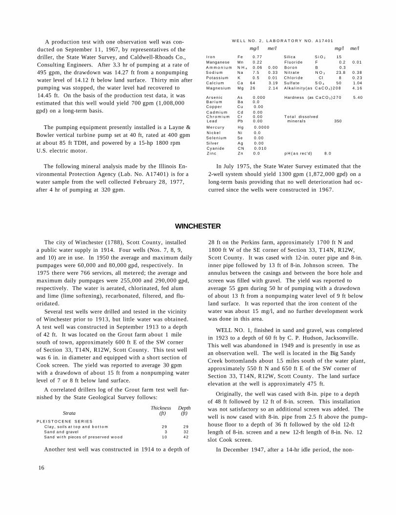
A production test with one observation well was conducted on September 11, 1967, by representatives of the driller, the State Water Survey, and Caldwell-Rhoads Co., Consulting Engineers. After 3.3 hr of pumping at a rate of 495 gpm, the drawdown was 14.27 ft from a nonpumping water level of 14.12 ft below land surface. Thirty min after pumping was stopped, the water level had recovered to 14.45 ft. On the basis of the production test data, it was estimated that this well would yield 700 gpm (1,008,000 gpd) on a long-term basis.
The pumping equipment presently installed is a Layne & Bowler vertical turbine pump set at 40 ft, rated at 400 gpm at about 85 ft TDH, and powered by a 15-hp 1800 rpm U.S. electric motor.
The following mineral analysis made by the Illinois Environmental Protection Agency (Lab. No. A17401) is for a water sample from the well collected February 28, 1977, after 4 hr of pumping at 320 gpm.
W E L L N O . 2 , L A B O R A T O R Y N O . A 1 7 4 0 1
mg/l me/l mg/l me/l I r o n Fe 0 .77 S i l i ca S i O 2 15 Manganese Mn 0 .22 F l u o r i d e F 0.2 0 .01 A m m o n i u m N H 4 0 . 06 0 . 0 0 B o r o n B 0.3 S o d i u m N a 7.5 0 . 3 3 N i t r a t e N O 3 23 .8 0 . 3 8 Po tass ium K 0 . 5 0 .01 C h l o r i d e Cl 8 0 . 2 3 C a l c i u m C a 6 4 3 .19 S u l f a t e S O 4 5 0 1 .04 Magnes ium M g 2 6 2 . 1 4 A l k a l i n i t y ( a s C a C O 3 ) 2 0 8 4 . 1 6
A r s e n i c As 0 . 0 0 0 Hardness (as C a C O 3 ) 2 7 0 5 . 4 0 B a r i u m Ba 0 .0 C o p p e r C u 0 . 0 0 C a d m i u m C d 0 . 0 0 C h r o m i u m C r 0 . 0 0 T o t a l d issolved Lead Pb 0 . 0 0 m inera ls 350 M e r c u r y H g 0 . 0 0 0 0 N i c k e l N i 0 .0 S e l e n i u m Se 0 . 0 0 S i l ver A g 0 . 0 0 C y a n i d e C N 0 . 0 1 0 Z i n c Z n 0 .0 p H ( a s rec 'd) 8 . 0
In July 1975, the State Water Survey estimated that the 2-well system should yield 1300 gpm (1,872,000 gpd) on a long-term basis providing that no well deterioration had occurred since the wells were constructed in 1967.
WINCHESTER
The city of Winchester (1788), Scott County, installed a public water supply in 1914. Four wells (Nos. 7, 8, 9, and 10) are in use. In 1950 the average and maximum daily pumpages were 60,000 and 80,000 gpd, respectively. In 1975 there were 766 services, all metered; the average and maximum daily pumpages were 255,000 and 290,000 gpd, respectively. The water is aerated, chlorinated, fed alum and lime (lime softening), recarbonated, filtered, and fluoridated.
Several test wells were drilled and tested in the vicinity of Winchester prior to 1913, but little water was obtained. A test well was constructed in September 1913 to a depth of 42 ft. It was located on the Grout farm about 1 mile south of town, approximately 600 ft E of the SW corner of Section 33, T14N, R12W, Scott County. This test well was 6 in. in diameter and equipped with a short section of Cook screen. The yield was reported to average 30 gpm with a drawdown of about 15 ft from a nonpumping water level of 7 or 8 ft below land surface.
A correlated drillers log of the Grout farm test well furnished by the State Geological Survey follows:
Thickness Depth Strata (ft) (ft)
P L E I S T O C E N E S E R I E S C l a y , soi ls a t t o p a n d b o t t o m 2 9 2 9 Sand a n d gravel 3 32 Sand w i t h pieces o f preserved w o o d 1 0 4 2
Another test well was constructed in 1914 to a depth of
28 ft on the Perkins farm, approximately 1700 ft N and 1800 ft W of the SE corner of Section 33, T14N, R12W, Scott County. It was cased with 12-in. outer pipe and 8-in. inner pipe followed by 13 ft of 8-in. Johnson screen. The annulus between the casings and between the bore hole and screen was filled with gravel. The yield was reported to average 55 gpm during 50 hr of pumping with a drawdown of about 13 ft from a nonpumping water level of 9 ft below land surface. It was reported that the iron content of the water was about 15 mg/l, and no further development work was done in this area.
WELL NO. 1, finished in sand and gravel, was completed in 1923 to a depth of 60 ft by C. P. Hudson, Jacksonville. This well was abandoned in 1949 and is presently in use as an observation well. The well is located in the Big Sandy Creek bottomlands about 1.5 miles south of the water plant, approximately 550 ft N and 650 ft E of the SW corner of Section 33, T14N, R12W, Scott County. The land surface elevation at the well is approximately 475 ft.
Originally, the well was cased with 8-in. pipe to a depth of 48 ft followed by 12 ft of 8-in. screen. This installation was not satisfactory so an additional screen was added. The well is now cased with 8-in. pipe from 2.5 ft above the pump-house floor to a depth of 36 ft followed by the old 12-ft length of 8-in. screen and a new 12-ft length of 8-in. No. 12 slot Cook screen.
In December 1947, after a 14-hr idle period, the non-
16

pumping water level was reported to be 19.0 ft below land surface.
On January 6-7, 1948, this well was acidized by Dowell, Inc. It was reported that the capacity was apparently increased but the amount was unknown.
WELL NO. 2, finished in sand and gravel, was constructed in 1914 to a depth of 42 ft, and deepened in 1938 to a reported depth of 62 ft. This well was abandoned prior to 1965 and is presently in use as an observation well. The well is located about 100 ft west of Well No. 1, approximately 550 ft N and 550 ft E of the SW corner of Section 33, T14N, R12W, Scott County. The land surface elevation at the well is approximately 475 ft.
The well is cased with 12-in. outer pipe from 2.5 ft above the pumphouse floor to a depth of 49 ft and an 8-in. inner pipe from 2.5 ft above the pumphouse floor to a depth of 49 ft followed by 1 3 ft of 8-in. Johnson brass screen. The annulus between the bore hole and casing-screen assembly is filled with sand and clay to an unknown depth and with gravel to 62 ft.
Upon completion of the well, the yield was reported to be 50 gpm.
In 1926, the nonpumping water level was reported to be 12 ft below land surface.
On January 6-7, 1948, this well was acidized by Dowell, Inc. It was reported that treatment increased the capacity of the well approximately 50 percent.
A partial analysis of a sample (Lab. No. 113118) collected January 7, 1948, after pumping for 20 hr at 55 gpm, showed the water to have a hardness of 407 mg/l, total dissolved minerals of 485 mg/l, and an iron content of 6.4 mg/l.
WELL NO. 3, finished in sand and gravel, was constructed in 1914 to a depth of 42 ft, and deepened in 1938 to a reported depth of 62 ft. This well was abandoned in 1965 and is presently in use as an observation well. The well is located about 100 ft west of Well No. 2, approximately 550 ft N and 450 ft E of the SW corner of Section 33, T14N, R12W, Scott County. The land surface elevation at the well is approximately 475 ft.
The well is cased with 12-in. outer pipe to a depth of 49 ft and an 8-in. inner pipe to a depth of 49 ft followed by 13 ft of 8-in. Johnson brass screen. The annulus between the bore hole and casing-screen assembly is filled with sand and clay to an unknown depth and with gravel to 62 ft.
Upon completion of the well, the yield was reported to be 50 gpm.
In 1926, the nonpumping water level was reported to be 12 ft below land surface.
On January 6-7, 1948, this well was acidized by Dowell, Inc. Because of the poor pump condition, it was impossible to determine the effect of the treatment.
On March 5, 1948, the nonpumping water level was reported to be 30 ft below the pump base.
A mineral analysis of a sample (Lab. No. 113693) collected March 5, 1948, showed the water to have a hardness of 345 mg/l, total dissolved minerals of 367 mg/l, and an iron content of 2.9 mg/l.
Prior to the construction of Well Nos. 4 and 5, eleven test holes located in Section 5, T13N, R12W, were drilled in August 1948 by Hayes & Sims, Champaign, to depths ranging from 39 to 55 ft deep.
WELL NO. 4, finished in sand and gravel, was completed in October 1949 to a depth of 47 ft by Hayes & Sims, Champaign. This well was abandoned in 1969. The well is located about 0.5 mile southwest of Well No. 3, approximately 1320 ft S and 2000 ft W of the NE corner of Section 5, T13N, R12W, Scott County. The land surface elevation at the well is 464.5 ft.
The well is cased with 16-in. OD steel pipe from 10 ft above land surface to a depth of about 37.6 ft and 8-in. ID pipe from 9.2 ft above land surface to a depth of 36.3 ft and equipped with 10 ft (11.1 ft overall length) of 8-in. No. 60 slot Johnson Everdur screen. The casing is in a concrete envelope extending 10 ft above land surface to provide flood protection. The annulus between the casings and between the bore hole and screen is filled with gravel.
A production test with two observation wells was conducted on October 27, 1949, by representatives of the driller, the city, the State Water Survey, and Crawford, Murphy & Tilly, Consulting Engineers. After 7 hr of pumping at rates ranging from 41 to 170 gpm, the drawdown was 18.3 ft from a nonpumping water level of 8.0 ft below land surface. Pumping was continued for 33 min at a rate of 225 gpm with a final drawdown of 20.0 ft. Forty min after pumping was stopped, the water level had recovered to 11.0 ft.
The pumping equipment presently installed is a 5.6-in., 13-stage Aurora turbine pump (No. 46721) rated at 125 gpm at about 122 ft TDH, and powered by a 7½-hp 1800 rpm U. S. Holloshaft electric motor.
A mineral analysis of a sample (Lab. No. 119768) collected October 27, 1949, after pumping for 8 hr at 225 gpm, showed the water to have a hardness of 394 mg/l, total dissolved minerals of 408 mg/l, and an iron content of 6.6 mg/l.
WELL NO. 5, finished in sand and gravel, was completed in November 1949 to a depth of 50 ft by Hayes & Sims, Champaign. This well was abandoned in 1969. The well is located about 270 ft south of Well No. 4, approximately 1590 ft S and 2000 ft W of the NE corner of Section 5, T13N, R12W, Scott County. The land surface elevation at the well is 464.6 ft.
The well is cased with 16-in. OD pipe from about 10 ft above land surface to a depth of about 40.4 ft and 8-in. ID pipe from 10 ft above land surface to a depth of 38.9 ft and equipped with 10 ft (11.2 ft overall length) of 8-in. No. 60 slot Johnson Everdur screen. The casing is in a
17
concrete envelope extending 10 ft above land surface to provide flood protection. The annulus between the casings and between the bore hole and screen is filled with gravel.
A production test using two observation wells was conducted on November 9, 1949, by representatives of the driller, the city, the State Water Survey, and Crawford, Murphy & Tilly, Consulting Engineers. After 8 hr of pumping at rates of 98 to 100 gpm, the drawdown was 25.0 ft from a nonpumping water level of 8.3 ft below land surface. The water level recovered to 10.0 ft after pumping had been stopped for 2.2 hr.
The pumping equipment presently installed consists of a 5-hp 1750 rpm U. S. Holloshaft electric motor, a 5.6-in., 8-stage Aurora turbine pump (No. 46722) rated at 75 gpm at about 112 ft head, and has 40 ft of 4-in. column pipe. The well is equipped with 40 ft of airline.
A mineral analysis of a sample (Lab. No. 119903) collected November 9, 1949, after pumping for 8 hr at 100 gpm, showed the water to have a hardness of 350 mg/l, total dissolved minerals of 375 mg/l, and an iron content of 6.1 mg/l.
WELL NO. 6, finished in sand and gravel, was completed in August 1964 to a depth of 45 ft by the Layne-Western Co., Kirkwood, Mo. This well is not in use. The well is located about 535 ft north of Well No. 5, approximately 1055 ft S and 2000 ft W of the NE corner of Section 5, T13N, R12W, Scott County. The land surface elevation at the well is approximately 464 ft.
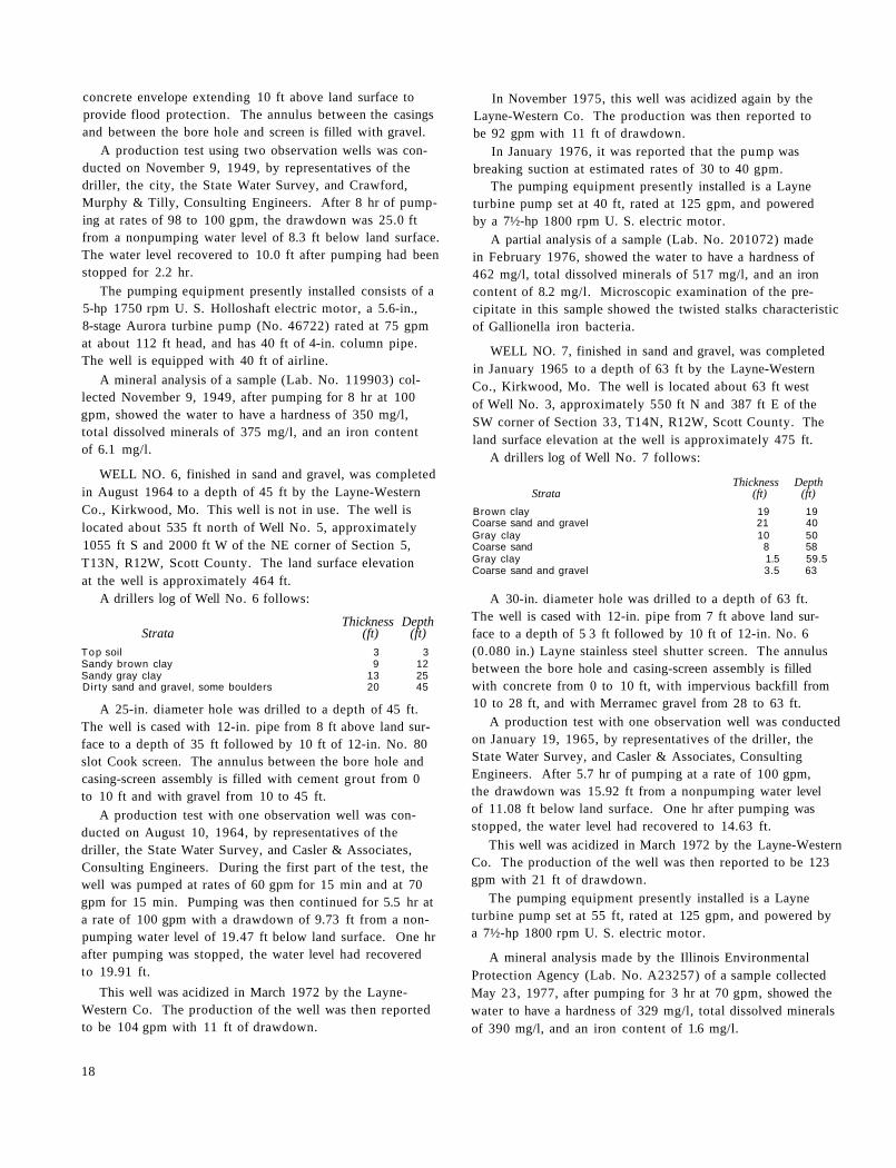
A drillers log of Well No. 6 follows:
Thickness Depth Strata (ft) (ft)
Top soil 3 3 Sandy brown clay 9 12 Sandy gray clay 13 25 Dirty sand and gravel, some boulders 20 45
A 25-in. diameter hole was drilled to a depth of 45 ft. The well is cased with 12-in. pipe from 8 ft above land surface to a depth of 35 ft followed by 10 ft of 12-in. No. 80 slot Cook screen. The annulus between the bore hole and casing-screen assembly is filled with cement grout from 0 to 10 ft and with gravel from 10 to 45 ft.
A production test with one observation well was conducted on August 10, 1964, by representatives of the driller, the State Water Survey, and Casler & Associates, Consulting Engineers. During the first part of the test, the well was pumped at rates of 60 gpm for 15 min and at 70 gpm for 15 min. Pumping was then continued for 5.5 hr at a rate of 100 gpm with a drawdown of 9.73 ft from a non-pumping water level of 19.47 ft below land surface. One hr after pumping was stopped, the water level had recovered to 19.91 ft.
This well was acidized in March 1972 by the Layne-Western Co. The production of the well was then reported to be 104 gpm with 11 ft of drawdown.
In November 1975, this well was acidized again by the Layne-Western Co. The production was then reported to be 92 gpm with 11 ft of drawdown.
In January 1976, it was reported that the pump was breaking suction at estimated rates of 30 to 40 gpm.
The pumping equipment presently installed is a Layne turbine pump set at 40 ft, rated at 125 gpm, and powered by a 7½-hp 1800 rpm U. S. electric motor.
A partial analysis of a sample (Lab. No. 201072) made in February 1976, showed the water to have a hardness of 462 mg/l, total dissolved minerals of 517 mg/l, and an iron content of 8.2 mg/l. Microscopic examination of the precipitate in this sample showed the twisted stalks characteristic of Gallionella iron bacteria.
WELL NO. 7, finished in sand and gravel, was completed in January 1965 to a depth of 63 ft by the Layne-Western Co., Kirkwood, Mo. The well is located about 63 ft west of Well No. 3, approximately 550 ft N and 387 ft E of the SW corner of Section 33, T14N, R12W, Scott County. The land surface elevation at the well is approximately 475 ft.
A drillers log of Well No. 7 follows:
Thickness Depth Strata (ft) (ft)
Brown clay 19 19 Coarse sand and gravel 21 40 Gray clay 10 50 Coarse sand 8 58 Gray clay 1.5 59.5 Coarse sand and gravel 3.5 63
A 30-in. diameter hole was drilled to a depth of 63 ft. The well is cased with 12-in. pipe from 7 ft above land surface to a depth of 5 3 ft followed by 10 ft of 12-in. No. 6 (0.080 in.) Layne stainless steel shutter screen. The annulus between the bore hole and casing-screen assembly is filled with concrete from 0 to 10 ft, with impervious backfill from 10 to 28 ft, and with Merramec gravel from 28 to 63 ft.
A production test with one observation well was conducted on January 19, 1965, by representatives of the driller, the State Water Survey, and Casler & Associates, Consulting Engineers. After 5.7 hr of pumping at a rate of 100 gpm, the drawdown was 15.92 ft from a nonpumping water level of 11.08 ft below land surface. One hr after pumping was stopped, the water level had recovered to 14.63 ft.
This well was acidized in March 1972 by the Layne-Western Co. The production of the well was then reported to be 123 gpm with 21 ft of drawdown.
The pumping equipment presently installed is a Layne turbine pump set at 55 ft, rated at 125 gpm, and powered by a 7½-hp 1800 rpm U. S. electric motor.
A mineral analysis made by the Illinois Environmental Protection Agency (Lab. No. A23257) of a sample collected May 23, 1977, after pumping for 3 hr at 70 gpm, showed the water to have a hardness of 329 mg/l, total dissolved minerals of 390 mg/l, and an iron content of 1.6 mg/l.
18

WELL NO. 8, finished in sand and gravel, was completed in May 1969 to a depth of 52 ft by the Layne-Western Co., Kirkwood, Mo. The well is located about 100 ft west and 745 ft south of Well No. 6, approximately 1800 ft S and 2100 ft W of the NE corner of Section 5, T13N, R12W, Scott County. The land surface elevation at the well is approximately 470 ft.
A drillers log of Well No. 8 follows:
Thickness Depth Strata (ft) (ft)
T o p soi l 2 2 B r o w n c lay 1 9 2 1 M e d i u m to coarse sand and g rave l , t h i n
c lay layers 31 52 Sha le 2 54
A 32-in. diameter hole was drilled to a depth of 10 ft and finished 24 in. in diameter from 10 to 52 ft. The well is cased with 24-in. outer pipe from 8 ft above land surface to a depth of 10 ft and 12-in. steel pipe from 8 ft above land surface to a depth of 42 ft followed by 10 ft of 12-in. No. 6 (0.080 in.) Layne shutter screen. The annulus between the casings and between the bore hole and casing-screen assembly is filled with concrete from 8 ft above land surface to a depth of 10 ft, with torpedo sand from 10 to 30 ft, and with gravel from 30 to 52 ft.
A production test with two observation wells was conducted on May 8, 1969, by representatives of the driller, the State Water Survey, and Casler & Associates, Consulting Engineers. After 2 hr of pumping at a rate of 180 gpm, the drawdown was 21.76 ft from a nonpumping water level of 8.03 ft below land surface. Thirty min after pumping was stopped, the water level had recovered to 10.34 ft.
This well was acidized in March 1972 by the Layne-Western Co. The production of the well was then reported to be 90 gpm with 10 ft of drawdown.
The pumping equipment presently installed is an 8-in., 5-stage Layne turbine pump set at 40 ft, rated at 125 gpm at about 147 ft TDH, and powered by a 7½-hp 1745 rpm General Electric motor (Model No. 5K6226XHIA).
A mineral analysis made by the Illinois Environmental Protection Agency (Lab. No. A23256) of a sample collected May 23, 1977, after pumping for 3 hr at 75 gpm, showed the water to have a hardness of 378 mg/l, total dissolved minerals of 460 mg/l, and an iron content of 10.5 mg/l.
WELL NO. 9, finished in sand and gravel, was completed in March 1976 to a depth of 46 ft by the Layne-Western Co., Kirkwood, Mo. The well is located about 65 ft south of Well No. 6, approximately 1120 ft S and 2000 ft W of the NE corner of Section 5, T13N, R12W, Scott County. The land surface elevation at the well is approximately 470 ft.
A drillers log of Well No. 9 follows:
Thickness Depth Strata (ft) (ft)
B r o w n c lay 6 6
Thickness Depth Strata (continued) (ft) (ft)
B l u e c lay 4 10 B r o w n c lay 7 17 B lue c lay 6 23 M e d i u m to coarse sand 10 33 S a n d , g rave l , bou lde rs 1 3 4 6 R o c k o r shale a t 4 6
A 24-in. diameter hole was drilled to a depth of 46 ft. The well is cased with 24-in. pipe from 8 ft above land surface to a depth of 12 ft and 12-in. pipe from 8.5 ft above land surface to a depth of 36 ft followed by 10 ft of 12-in. No. 5 (0.105 in.) Layne stainless steel shutter screen. The annulus between the 24- and 12-in. casings and between the bore hole and 12-in. casing-screen assembly is filled with cement from 8 ft above land surface to a depth of 10 ft and with 4 tons of WB50 gravel from 10 to 46 ft.
A production test using one observation well was conducted by the driller on March 22, 1976. After 3.8 hr of pumping at a rate of 100 gpm, the drawdown was 11.90 ft from a nonpumping water level of 12.93 ft below land surface. Thirty min after pumping was stopped, the water level had recovered to 15.10 ft.
The pumping equipment presently installed is a Layne vertical turbine pump set at 40 ft, rated at 100 gpm, and powered by a 7½-hp U. S. Holloshaft electric motor.
The following mineral analysis made by the Illinois Environmental Protection Agency (Lab. No. A7067) is for a water sample from the well collected in September 1976, after 6 hr of pumping at 100 gpm.
W E L L N O . 9 , L A B O R A T O R Y N O . A 7 0 6 7
mg/l me/l mg/l me/l I r o n F e 10 .0 Si l ica S i O 2 1 8 Manganese Mn 0.2 F l uo r i de F 0 .2 0 .01 A m m o n i u m N H 4 1.0 0 . 0 6 Boron B 0.1 S o d i u m N a 10.2 0 . 4 4 N i t r a te N O 3 0 .0 Po tass ium K 0.7 0 . 0 2 Ch lo r i de Cl 10 0 . 2 8 C a l c i u m C a 1 0 0 . 0 4 . 9 9 Su l fa te S O 4 2 0 0 . 4 2 Magnes ium Mg 4 1 . 0 3 .37 A l k a l i n i t y (as C a C O 3 ) 4 1 0 8 . 2 0
A rsen ic As 0 . 0 2 0 B a r i u m Ba 0.0 Hardness (as C a C O 3 ) 4 3 6 8 . 7 2 C o p p e r C u 0 .00 C a d m i u m Cd 0 .00 To ta l d isso lved C h r o m i u m C r 0 .05 minera ls 4 9 0 Lead Pb 0 .00 M e r c u r y H g 0 . 0 0 0 0 N i c k e l N i 0.0 S e l e n i u m Se 0 .00 Si lver Ag 0 . 0 0 C y a n i d e C N 0 .005 Z i n c Zn 0 .0 pH (as rec 'd ) 7.1
WELL NO. 10, finished in sand and gravel, was completed in March 1977 to a depth of 48 ft by the J. P. Miller Artesian Well Co., Brookfield. The well is located about 270 ft south of Well No. 9, approximately 1390 ft S and 2000 ft W of the NE corner of Section 5, T13N, R12W, Scott County. The
19

land surface elevation at the well is approximately 472 ft. A drillers log of Well No. 10 follows:
Thickness Depth Strata (ft) (ft)
Gray clayey silt 8 8 Brown silty clay 13 21 Gray silty clay 5 26 Sand and gravel w i th cobble and boulders 22 48 Gray silt
A 48-in diameter hole was drilled to a depth of 11 ft and finished 30 in. in diameter from 11 to 48 ft. The well is cased with 24-in. pipe from 7 ft above land surface to a depth of 10 ft and 12-in. pipe from 8 ft above land surface to a depth of 38 ft followed by 10 ft of 12-in. No. 80 slot screen. The annulus between the bore hole and casing-screen assembly is filled with concrete from 7 ft above land surface to a depth of 10.5 ft, with sand fill from 10.5 to 25 ft, and with gravel from 25 to 48 ft.
A production test was conducted by the driller on March 11, 1977. After 3.8 hr of pumping at rates of 75 to 70 gpm, the drawdown was 9.50 ft from a nonpumping water level of 25.00 ft below land surface. Pumping was continued for 1.5 hr at rates of 60 to 50 gpm with a final drawdown of 7.08 ft. Fifteen min after pumping was stopped, the water level had recovered to 25.08 ft. On the basis of the production test data, the Water Survey estimated that this well should yield 60 gpm (86,400 gpd) on a long-term basis.
The pumping equipment presently installed is a 4.8-in., 7-stage Fairbanks-Morse vertical turbine pump set at about 35.5 ft below the pump base, rated at 125 gpm at about 164.5 ft TDH, and powered by a 7.5-hp electric motor.
A partial analysis of a sample (Lab. No. 204553) collected during the initial production test, after pumping for 4 hr at rates of 75 to 50 gpm, showed the water to have a hardness of 370 mg/l, total dissolved minerals of 397 mg/l, and an iron content of 1.3 mg/l.
Printed by authority of the State of Illinois (3-79-1200)
20