ptree: a system for flexible, efficient packet classification: hardware ... · ptree: a system for...
TRANSCRIPT
PTREE: A System for Flexible, Efficient Packet Classification: Hardware Implementation
CS535, Fall 2001 Derek Becker, Manoj Singla, Radivoje Todorovic, Qiheng Wang

CS535, Fall 2001 Derek Becker Manoj Singla Radivoje Todorovic Qiheng Wang
Page 2 of 35
PTREE: A SYSTEM FOR FLEXIBLE, EFFICIENT PACKET CLASSIFICATIO N: HARDWARE IMPLEMENTATION ..................................................................................................................................................1
1 INTRODUCTION ..............................................................................................................................................3 1.1 BACKGROUND.............................................................................................................................................. 3 1.2 DESIGN .......................................................................................................................................................... 4
2 SYSTEM ARCHITECTURE ..........................................................................................................................5 2.1 MAIN COMPONENTS................................................................................................................................... 6
2.1.1 Input Controller: ...................................................................................................................................6 2.1.2 Tree Update............................................................................................................................................6 2.1.3 Tree Parser.............................................................................................................................................6 2.1.4 Output Controller..................................................................................................................................6
2.2 OTHER COMPONENTS................................................................................................................................. 6 2.2.1 SRAM Arbiter.........................................................................................................................................6 2.2.2 Address FIFO ........................................................................................................................................6 2.2.3 CRC32.....................................................................................................................................................7 2.2.4 InCellBuffer............................................................................................................................................7 2.2.5 Passthru ..................................................................................................................................................7 2.2.6 BufferFIFO.............................................................................................................................................7
3 IMPLEMENTATION........................................................................................................................................7 3.1 INPUT PROCESSING COMPONENTS............................................................................................................. 7
3.1.1 Memory management ...........................................................................................................................8 3.1.2 Input processing ....................................................................................................................................8 3.1.3 Input processing entity interface......................................................................................................10
3.2 TREE UPDATE............................................................................................................................................ 13 3.2.1 TreeUpdate Component.....................................................................................................................15
3.3 TREE PARSER............................................................................................................................................. 15 3.3.1 Operational description.....................................................................................................................17
3.4 OUTPUT CONTROLLER.............................................................................................................................. 21 3.4.1 Operational description.....................................................................................................................21 3.4.2 Interface: ..............................................................................................................................................23
3.5 SRAM ARBITER........................................................................................................................................ 25 3.6 ADDRESS FIFO .......................................................................................................................................... 25
4 TESTING AND PERFORMANCE EVALUATION..............................................................................25 4.1 RESULTS..................................................................................................................................................... 25 4.2 SIMULATION RESULTS.............................................................................................................................. 26 4.3 SYNTHESIS RESULTS................................................................................................................................. 32
5 FUTURE WORK..............................................................................................................................................33
6 CONCLUSION ..................................................................................................................................................33
7 REFERENCES ..................................................................................................................................................34

CS535, Fall 2001 Derek Becker Manoj Singla Radivoje Todorovic Qiheng Wang
Page 3 of 35
1 Introduction Packet classification has become an increasingly important area of research in high speed networking. Both high speed routing techniques, such as MPLS or burst switching and policy enforcement mechanisms such as DiffServ or RSVP require fast and efficient methods for classifying packets into different flows. Additionally, the breadth of protocols that may traverse these networks and their high rate of change benefit from classification systems that are flexible and can accommodate new or modified protocols easily. In this paper we will describe the hardware implementation of a fast, flexible packet classification engine as described in [8].
1.1 Background Packet classification has been an active research area for many years. Many modern operating systems and networking devices include capabilities for packet classification, usually for the purpose of enforcing security, routing or other policies. There have been several approaches to packet classification systems, all of which have particular strengths and weaknesses. The simplest approach is to create a table containing values to be checked against the fields in a packet. As each packet arrives at the classifier, the classification engine checks each entry in the table against the packet, usually accepting the first match. The obvious downside to this approach is that the performance scales linearly both in the number of entries in the table, and in the number of fields that are to be checked. Additionally, once the classification engine has been compiled and installed it is impossible to change the fields that may be compared against without recompiling and deploying a new engine and possibly new tools. Another approach is to utilize a byte-code interpreted FSM to algorithmically match packets. The most significant example of this is the Berkeley Packet Filter (BPF) [2]. The engine contains pseudo registers which can be used to store packet data during matching, and gives both good performance and a high degree of flexibility. The original BPF has the drawback that it does not scale well with increasing rule counts or multiple matching agents. Recent modifications in the form of BPF+ have taken some of these shortcomings into consideration and appear to improve the performance of filter instances, but multiple user-space agents are not addressed [3]. More recent classification techniques have exploited common comparisons between rules to improve the efficiency of classifying packets over large rule sets. Examples include PATHFINDER and Grammar Base Filtering (GBF). Both PATHFINDER and GBF use pattern matching algorithms to classify packets. The PATHFINDER packet classification system is based on a DAG (directed acyclic graph) that contains composited cells, or units of comparison [4]. Independent rules can

CS535, Fall 2001 Derek Becker Manoj Singla Radivoje Todorovic Qiheng Wang
Page 4 of 35
be composed together in a longest-prefix-match fashion. PATHFINDER also allows for postponed classification of packets such as fragments or out-of-order packets, although this significantly increases the complexity of the classifier. Grammar Based Filtering applies compiler theory to the problem of packet classification by building an engine that “accepts” packets as though they were defined by a grammar [5]. The system takes a specification for a packet using bits as the tokens, and creates and LR(1) parser to accept or reject the packet. This system allows for composition of multiple independent rules and was shown to have good performance characteristics. However, in order to achieve this good performance the concept of skippable tokens must be introduced, which has the overall effect of making the preprocessing for GBF relatively complex. Based on our observations of the strengths and weaknesses of these previous works, it was our goal to design and implement a system that was as efficient and flexible as possible while keeping the algorithms simple and the performance high.
1.2 Design The mechanism of tree-based packet classification offers bounded, high performance packet matching for multiple agents with a relatively simple set of data structures and preprocessing algorithms. The classifier is implemented as a multi-way tree with comparisons (represented by branches) at specific packet offsets (represented by nodes). A set of registers is used to compute offsets of variable length headers for use within the engine. The height of the tree is bounded by the number of fields used by rules and the number of comparisons at each node is bounded by the number of rules in the system. It is clear, however, that with these bounds there will be a tradeoff in space requirements for the tree structure. The basis of the packet classification engine is the construct we will call a field. A field could be a source address, tcp port, header length field, etc. A field is defined as a position and size and has a one-to-one correspondence to a node in the parse tree. In order to achieve a high degree of flexibility in the classifier, the field positions within a packet are defined as base and offset pointers (in bytes) relative to the start of the packet. Individual fields can be tagged as length fields in which case the engine will copy the field’s value into a pseudo register that has been determined during the preprocessing stage. Later fields can use the value stored in the pseudo register as their base pointer value. Additionally, a length field’s value can be multiplied by a constant factor in order to allow for length fields that do not specify bytes, such as the IP header field hlen. The classification consists of a simple tree-walk algorithm. At each node (field) the node’s value in the packet is compared against each branch at that node, and the first match is taken. As the classifier visits each node it keeps track of the rules that have matched along the path the classifier has taken through the tree. It then determines whether the current node is designated a length field, and if so, it stores its value into a predetermined pseudo register. The classifier then compares the packet value against the

CS535, Fall 2001 Derek Becker Manoj Singla Radivoje Todorovic Qiheng Wang
Page 5 of 35
comparison values of each branch and follows the first match. It then repeats the procedure on the following node. The classifier engine stops when it reaches a leaf node or when none of the comparison branches match. While the space requirements would appear at first glance to make tree-based packet classification less than desirable, on further examination of a typical set of rules we will see that the space requirements appear to be reasonable for a large subset of all possible rules. Based on observations in [7] we see that the lion’s share of rulesets contain a small number of rules. The mean reported in [7] was 50 rules, with the majority of rulesets containing under 1000 rules. In the two years since [7] was published we have not seen evidence that this has changed drastically. It was also observed that the ma jority of rules used in classifiers contain a small number of field comparisons, and that a significant portion of the fields used are common between many rules and are confined to a small set of values. The result of these observations is that most fields will be shared by multiple rules, reducing the space requirements of each rule involved, and that early field matching in the packet will quickly reduce the number of comparisons to a small subset of the whole ruleset.
2 System Architecture
Figure 1 - System architecture

CS535, Fall 2001 Derek Becker Manoj Singla Radivoje Todorovic Qiheng Wang
Page 6 of 35
2.1 Main Components
2.1.1 Input Controller: The InputController is responsible to reassemble ATM cells into IP packets, allocate memory and request memory operation from SRAMArbiter, classify packets into either data or control FIFO. It interfaces with InCellBuffer, BufferFIFO, DataFIFO, ControlFIFO and SRAMArbiter.
2.1.2 Tree Update The TreeUpdate component is responsible for maintaining the tree data structure in memory and for reporting statistics about the system. It interfaces directly with SRAMArbiter, the TreeParser component, the incoming Control Address FIFO and the return path PassThru.
2.1.3 Tree Parser The treeParser component is responsible for performing “match” operation on the appropriate packet headers fields by comparing against the values stored in the tree nodes. It interfaces directly with SRAM (sramArbiter), the treeUpdate component, the incoming Data Address FIFO and downstream priority address FIFOs.
2.1.4 Output Controller The output controller provides the priority based de-queuing of the packets. It takes the address of the packet from the queue and reads it from the SRAM and output it in ATM cells. It also generates the CRC32 checksum and appends at the last word in the last cell of the packet. As soon the packet is sent out, the address of the first word of the packet (i.e. or the slot number) is pushed onto the queue containing the free slots or addresses. The addresses in free queue are used by the Input Controller to store new packets.
2.2 Other Components
2.2.1 SRAM Arbiter The sramArbiter provides prioritized access to SRAM memory while attempting to maintain a fair distribution of access across all components.
2.2.2 Address FIFO

CS535, Fall 2001 Derek Becker Manoj Singla Radivoje Todorovic Qiheng Wang
Page 7 of 35
The AddressFIFO component implements a simple FIFO for holding SRAM address pointers.
2.2.3 CRC32 The CRC-32 generator [9] is used to computer the CRC-32 checksum appended at the end of an AAL5 frame.
2.2.4 InCellBuffer The InCellBuffer takes in ATM cells as a 14, 32bit words. It also checks the protocol field in the IP header to see if it is control packet. After the InCellBuffer buffers a whole ATM cell, it will assert high on w_req signal to InputController. At the same time it put the first word of ATM cell on the data bus for InputController to check the VPI/VCI and last PT bit to decide if this cell is the last cell for an AAL5 frame.
2.2.5 Passthru The PassThru component handles the outbound path of the TreeFilter module. It serves to multiplex between outbound frames sent by the output processor and ACK packets sent by the treeUpdate component. It does this by buffering incoming cells from the output controller and the treeUpdate component and deciding which cell to send based on information in the ATM header for each cell. The primary criterium is that if the incoming cell from the output controller is in the middle of a frame (i.e. first cell has been seen and the PT is not EOF) then it takes priority. Otherwise, the treeUpdate ACK cell is sent.
2.2.6 BufferFIFO BufferFIFO is designed form fast memory management and it actually a list of free SRAM memory slot. It is initialized with sequential address pointer of memory slot. The first address will be used to store the next IP packet and the next released slot will be pushed into BufferFIFO.
3 Implementation
3.1 Input processing components Input processing components include InputController, InCellBuffer, BufferFIFO, DataFIFO and CtrlFIFO.

CS535, Fall 2001 Derek Becker Manoj Singla Radivoje Todorovic Qiheng Wang
Page 8 of 35
3.1.1 Memory management We allocate a block of memory in SRAM to store packets. The memory block is further divided into a number of slots, each of which has a size of 1508 bytes (1500 byte frame + 8 bytes ATM header). All of the slot addresses are initialized in the BufferFIFO when the system is reset. In this regard, the BufferFIFO acts as a free slot pointer list. When the InputController receives a request from the InCellBuffer, it will check if there is a free address in the BufferFIFO. If there is, it will pop a free slot address where it will store the packet. The slot is released after the OutputController sends out the packet by pushing the (now free) address onto the end of the BufferFIFO. This memory management provides quick slot lookup times because we eliminate procedures for searching for available memory addresses.
3.1.2 Input processing The bubble diagram of InputController is shown below:

CS535, Fall 2001 Derek Becker Manoj Singla Radivoje Todorovic Qiheng Wang
Page 9 of 35
The InCellBuffer takes in ATM cells as a 14, 32bit words. It also checks the protocol field in the IP header to see if it is control packet. In our implementation we define IP proto 0x42, i.e. decimal 66 as control protocol. All other protocols are processed as data packets. After the InCellBuffer buffers a whole ATM cell, it will assert high on the w_req signal to the InputController. At the same time it puts the first word of the ATM cell on the data bus so that the InputController can check the VPI/VCI and last PT bit to decide if this cell is the last cell for an AAL5 frame. Single VPI/VCI flows are assumed in this project. When a new packet comes, the VPI/VCI, IP packet length in ATM header will be cached in registers. The ATM header of the first cell is stored in SRAM. The ATM header of further cells composing the frame will be peeled off and only the payload data is stored in SRAM. For every byte of packet payload written into SRAM, we decrement the

CS535, Fall 2001 Derek Becker Manoj Singla Radivoje Todorovic Qiheng Wang
Page 10 of 35
remaining packet length counter. When the last cell of an IP packet comes, and the last byte of the data is stored in the SRAM, the counter will be zero and the padding and AAL5 trailer are removed. Our implementation currently does not check either the HEC or the AAL5 CRC-32, so we assume uncorrupted data. If the packet is a data packet, the address of the memory slot will be pushed onto the DataFIFO; if it is a control packet, it will be pushed onto the CtrlFIFO.
3.1.3 Input processing entity interface
3.1.3.1 InputController Interface
3.1.3.1.1 InCellBuffer interface W_req This signal is asserted high to the InputController interface to request and hold access to memory. The module must hold this signal high until the memory transaction is complete. W_grant This signal is asserted high to the InCellBuffer when the SRAM interface grants the InputController access to memory. The InCellBuffer must complete its current transactions and release the memory by deasserting its request signal. W_data [35:0] This 36bit data bus carries write data to memory. Write data must be issued during the same clock cycle that address and write (SRAM_RW = 0) are asserted. Data will be written to memory 4 clock cycles after the write signal, address, and data are asserted. W_control This signal is asserted high to the InputController interface to indicate the cell is one or part of one control packet. In our implementation, control packet is always a one-cell frame, i.e. last bit of PT field set to 1.
3.1.3.1.2 SRAMArbiter interface Input_req After receiving w_req from InCellBuffer and verify that there is free memory slot in the SRAM, InputController will assert high on this signal to SRAMarbiter to request memory operation. The InputController must complete its current transactions and release the memory by deasserting its request signal. Input_grant This signal is asserted high to the InputController when the SRAMarbiter interface grants the InputController access to memory. The InCellBuffer must complete its current transactions and release the memory by deasserting its request signal.

CS535, Fall 2001 Derek Becker Manoj Singla Radivoje Todorovic Qiheng Wang
Page 11 of 35
input_rw This signal specifies the type of memory access. High assertion specifies a read, while a low assertion specifies a write. The module should hold this signal high (READ) except when asserting it low (WRITE) with the address and data for a write transaction to prevent overwriting valid memory contents. Input_addr This 18bit address bus carries the memory address for reads and writes. Input_d_in This 36bit data bus carries read data from memory. Read data is available 4 clock cycles after the read signal and address are asserted. Input_d_out This 36bit data bus carries write data to memory. Write data must be issued during the same clock cycle that address and write (SRAM RW = 0) are asserted. Data will be written to memory 4 clock cycles after the read signal, address, and data are asserted.
3.1.3.1.3 DataFIFO interface Datafifo_is_full This signal carries the status of the DataFIFO. If asserted high, InputController will not push newly stored data packet slot address into BufferFIFO. Datafifo_addressIn This 18bit address bus carries the memory address for newly stored data packet. Datafifo_pushAddress This signal is the actual control signal for DataFIFO. When asserted high, the address carried by Datafifo_addrssIn will be pushed into DataFIFO and internal packet counter is incremented by 1.
3.1.3.1.4 CtrlFIFO interface Ctrlfifo_is_full This signal carries the status of the CtrlFIFO. If asserted high, InputController will not push newly stored control packet slot address into BufferFIFO. Ctrlfifo_addressIn This 18bit address bus carries the memory address for newly stored control packet. Ctrlfifo_pushAddress This signal is the actual control signal for CtrlFIFO. When asserted high, the address carried by Ctrlfifo_addrssIn will be pushed into CtrlFIFO and internal packet counter is incremented by 1.
3.1.3.1.5 bufferFIFO interface Buffer_not_ready This signal carries the status of the BufferFIFO. If asserted high, InputController will not be able to pop a free slot address out of BufferFIFO.
CS535, Fall 2001 Derek Becker Manoj Singla Radivoje Todorovic Qiheng Wang
Page 12 of 35
Buffer_addressIn This 18bit address bus carries the memory address for a free slot address. Buffer_popAddress This signal is the actual control signal for BufferFIFO. When asserted high, the first free slot address will be put on the Buffer_addressIn bus and the internal free list counter will be decremented by 1.
3.1.3.2 BufferFIFO interface Is_empty This signal carries the status of the BufferFIFO. If asserted high, InputController will not be able to pop a free slot address out of BufferFIFO. AddressOut This 18bit address bus carries the memory address for a free slot address. PopAddress This signal is the actual output control signal for BufferFIFO. When asserted high, the first free slot address will be put on the Buffer_addressIn bus and the internal free list counter will be decremented by 1. Is_full This signal carries the status of the BufferFIFO. If asserted high, InputController will not be able to pop a free slot address out of BufferFIFO. AddressIn This 18bit address bus carries the memory address for a free slot address just released. PushAddress This signal is the actual input control signal for BufferFIFO. When asserted high, the released free slot address will be put on the AddressIn bus and pushed into BufferFIFO. The internal free list counter will be incremented by 1.
3.1.3.3 DataFIFO and CtrlFIFO interface The DataFIFO and CtrlFIFO are two instances of AddressFIFO.
3.1.3.4 AddressFIFO interface The AddressFIFO implements a simple FIFO that holds SRAM memory addresses (18 bit words). It implements the following signals. Is_full When this signal is asserted high it indicates that the FIFO is full and cannot accept more addresses.

CS535, Fall 2001 Derek Becker Manoj Singla Radivoje Todorovic Qiheng Wang
Page 13 of 35
Is_empty When this signal is asserted high it indicates that there are no addresses currently in the FIFO. PushAddress When this signal is asserted high, the FIFO adds the current value of addressIn onto the end of the FIFO. The address to push and pushAddress must be asserted on the same cycle. PopAddress When this signal is asserted high, the FIFO will take the first address value in the FIFO and place it onto addressOut on the next cycle. AddressIn The input address for the FIFO. AddressOut The output address for the FIFO.
3.2 Tree Update
The TreeUpdate component acts as a control interface for updating the tree data structure in memory. Although it must maintain atomic operations on the tree by locking out the TreeParser during memory updates, it does not check incoming update packets for validity (i.e. bounds checking, packet format, etc.) Currently it is the responsibility of the
CS535, Fall 2001 Derek Becker Manoj Singla Radivoje Todorovic Qiheng Wang
Page 14 of 35
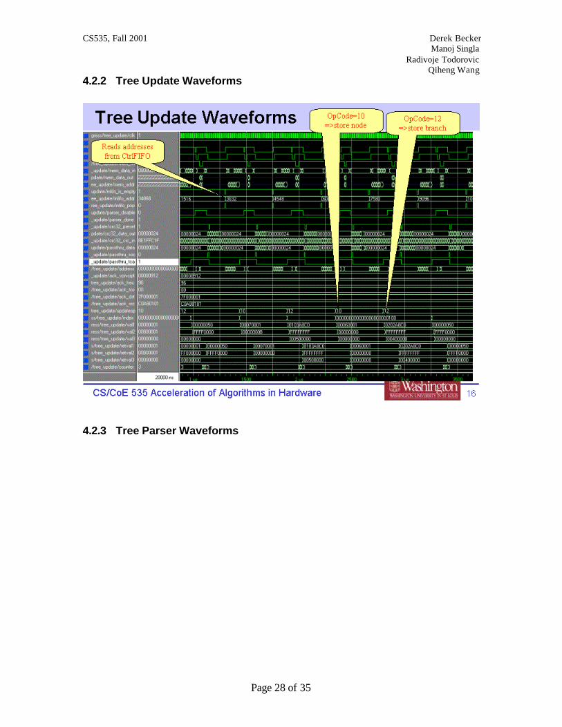
control software to verify that operations were performed correctly by checking the ACK packet values; for every control packet that updates the tree structure, the TreeUpdate module returns an acknowledgement with the values used in the update. Additionally, the TreeUpdate component can easily be extended to handle operations that extract statistics from the TreeParser module or other components within the Filter module. In this respect, the TreeUpdate component represents the general control interface for the Filter module. The operation of the TreeUpdate component is straightforward. When the incoming control packet address FIFO becomes non-empty, the TreeUpdate module pops the buffer pointer off and initiates a read of the packet into internal registers. The control packets are encapsulated in IP protocol 66 packets. The registers save the following fields from the incoming control packet:
• ATM header • ToS field • IP Source • IP Destination
The ATM header is saved to avoid HEC recalculation and to ensure that ACK packets go out on the same virtual circuit they arrived on. We also save the ToS field in case control packets are using a different priority from other data packets. The IP source and destination are reversed when the packet is read in so that the ACK packet will return to the sender. Depending on the operation field of the control packet, the TreeUpdate component takes one of several actions. If the operation specifies a memory update (NODE_OP=0x10 or BRANCH_OP=0x12) then the TreeUpdate component signals the TreeParser to stop after it finishes processing its current packet (if any). When the TreeParser notifies the TreeUpdate component that it is finished we then request memory access and write the packet payload into memory. We then begin to send an acknowledgement/statistic packet. If the operation does not involve memory (statistics or other control functions) then we collect the data or perform the function and the send the ACK packet with the results. The TreeUpdate component sends a return ACK packet on the same VPI/VCI as the original packet encapsulated in a single-cell AAL5 IP protocol 66 datagram. In order to perform the encapsulation correctly, the TreeUpdate utilizes a CRC-32 generator found in [ref] to compute the AAL5 checksum of the cell payload as it sends the cell data. When the ACK finishes transmitting the payload it appends the AAL5 length trailer and the one's complement of the CRC-32 generator output to the end of the cell.
CS535, Fall 2001 Derek Becker Manoj Singla Radivoje Todorovic Qiheng Wang
Page 15 of 35
3.2.1 TreeUpdate Component
3.2.1.1 CtlFIFO Interface The CtlFIFO is the address fifo for incoming control packets. The treeUpdate component waits for the infifo_is_empty signal to go low, then asserts the infifo_pop signal. On the next cycle the address of the next control packet is available on infifo_addr.
3.2.1.2 SRAM Interface Signals starting with “mem_” represent the abstracted SRAM interface as described in [9].
3.2.1.3 Parser Interface In order to provide atomic tree update operations, it is necessary to lock the treeParser component before write occur. In order to do this, the parser_disable signal is asserted and the treeUpdate component then waits until the parser_done signal is also asserted. The treeUpdate component holds parser_disable high until it has completed the memory operation.
3.2.1.4 CRC Interface The CRC-32 generator is used to compute the CRC-32 checksum at the end of the AAL5 ACK frame returned for each control packet. In the cycle preceding the first payload word, the crc32_preset signal is asserted low to reset the generator’s checksum. Each word of the payload is copied to crc32_data_out as it is sent and at the end of the cell the CRC-32 checksum is computed as the one’s complement of the value of crc32_crc_in.
3.2.1.5 PassThru Interface The passThru interface provides the return path for acknowledgement packets. It presents itself to the treeUpdate component as a general RAD cell interface (passthru_data, passthru_tca, passthru_soc).
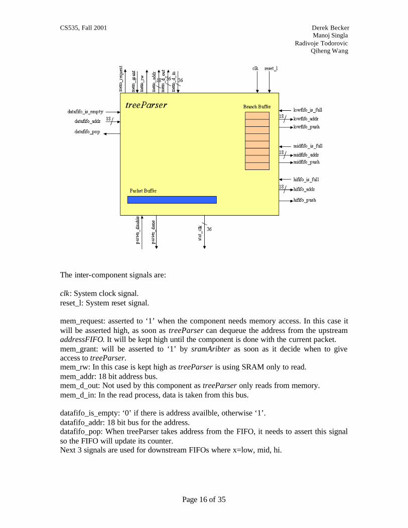
3.3 Tree Parser Tree parser entity is given on the next figure:
CS535, Fall 2001 Derek Becker Manoj Singla Radivoje Todorovic Qiheng Wang
Page 16 of 35
The inter-component signals are: clk: System clock signal. reset_l: System reset signal. mem_request: asserted to ‘1’ when the component needs memory access. In this case it will be asserted high, as soon as treeParser can dequeue the address from the upstream addressFIFO. It will be kept high until the component is done with the current packet. mem_grant: will be asserted to ‘1’ by sramAribter as soon as it decide when to give access to treeParser. mem_rw: In this case is kept high as treeParser is using SRAM only to read. mem_addr: 18 bit address bus. mem_d_out: Not used by this component as treeParser only reads from memory. mem_d_in: In the read process, data is taken from this bus. datafifo_is_empty: ‘0’ if there is address availble, otherwise ‘1’. datafifo_addr: 18 bit bus for the address. datafifo_pop: When treeParser takes address from the FIFO, it needs to assert this signal so the FIFO will update its counter. Next 3 signals are used for downstream FIFOs where x=low, mid, hi.

CS535, Fall 2001 Derek Becker Manoj Singla Radivoje Todorovic Qiheng Wang
Page 17 of 35
xfifo_is_full: ‘1’ signals that downstream FIFO is full and treeParser cannot “write” the address into it. xfifo_addr: 18 bit address bus xfifo_push: Once the address is placed on the address bus, this signal is asserted so that downstream FIFO can update its counters. parser_disable: while this signal is ‘1’ then treeParser is in its start state and the control is under treeUpdate. parser_done: Once the treeParser is done with processing the current packet, it will assert this signal to high so the treeUpdate could take the access to the tree storage area in the SRAM. stat_clk: 32 bit data bus tha t represents cumulative statistics for the number of CLK cycles spent during parser operation on the packet
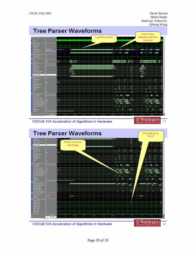
3.3.1 Operational description The treeParser component is the main component of the system and directly implements our algorithm designed in CS524. Assuming the tree with the matching rules is stored in the SRAM, treeParser “loads” up to 100 bytes of the packet into a local cache register. Thereafter the treeParser reads the current node from the SRAM. The node is stored as two 36 bit SRAM words(shaded areas represents unused bits)
branchOffset: 16 bit field used to determine the offset into a memory where the branch set for this node starts. For example, the memory address from which treeParser will start reading up to 8 branches for this node is calculated as: cur_branch_address(17 downto 0) <= conv_std_logic_vector(c_BranchOffset + conv_integer(branchOffset)*3,18); noBranches: The number of branches this node contains (16 bits) action: The action to be taken if the packet ends up matching this node. For the purpose of this project we have defined only three actions:
- enqueue to the Low Priority Queue. - enqueue to the Mid Priority Queue. - enqueue to the Hi Priority Queue.

CS535, Fall 2001 Derek Becker Manoj Singla Radivoje Todorovic Qiheng Wang
Page 18 of 35
base: Index in the local register where we hold values of the total offset for the current packet header. Initial index of zero has value of zero as we start from the IP header. For example if we are currently matching against the value in the TCP header, then gRegister[base=1]=20 would satisfy the case when IP header is exactly 20 bytes long. hdrLenFieldFlag: One bit flag that determines whether the current node contains header length field. fieldOffset: 11 bit field that determines the byte offset of the current match field from the current header. multiplier: 4 bit field that determines the multiplier value for the calculation of the current header length. This is valid only for variable length headers. lenFieldOffset: Gives the offset in bytes for the current position of the length field. sz: Enumerator that determines the type of the header length field.
- “00” – the length is in upper nibble of the byte - “01” - the length is in upper nibble of the byte - “10” – the length is in the whole byte.
The logic then reads up to 8 branches into a local cache. Each branch is stored in a memory as three SRAM words:
Value : 32 bit field that is used for matching the value in the packet. Mask: 32 bit value used to mask actual value in the packet as the field to compare may be one, two or 4 bytes long. nxtNodeOffset: 12 bit field used to determine the offset into a memory where next node starts. For example, the memory address from which treeParser will start reading next node is calculated as: cur_node_address <= conv_std_logic_vector(c_NodeOffset + conv_integer(branchBuffer(brBuffIndex+2)(11 downto 0)) *2,18);

CS535, Fall 2001 Derek Becker Manoj Singla Radivoje Todorovic Qiheng Wang
Page 19 of 35
Once everything is locally ready for the comparisons the logic traverse through the local branch buffer and checks if the value in the branch matches the value in the packet on the appropriate position. If the value to match is actually the header length-field, then the we load the local register with the header length as described above. Otherwise we simply match the packet value against the value in the branch. If we found the match, then we go to the next node. If there is no more nodes we simply enqueue the packet address into the appropriate downstream FIFO. In a case there is no match we repeat the operation for the next branch in the buffer array. If we cannot find the match in any of the branches then, by default, we enqueue the packet into a Low Priority Queue. Simplified Bubble diagram is given below:

CS535, Fall 2001 Derek Becker Manoj Singla Radivoje Todorovic Qiheng Wang
Page 20 of 35
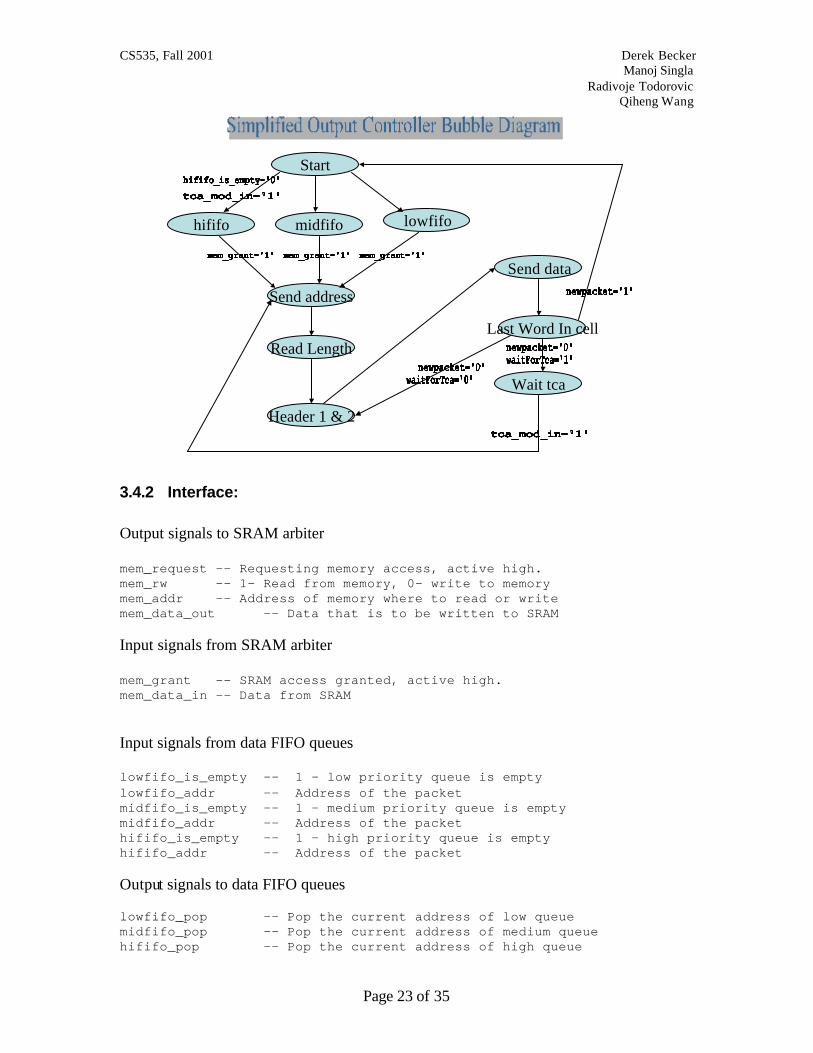
We begin from the start state where the logic will wait for the available address in the upstream FIFO and for the parser_disable=’0’ from the treeParser. Thereafter it will issue mem_request and once it is granted it will read up to 100 bytes of the packet into a local cache. After reading the node and up to 8 branches (stored in the local cache), the circuit will then try to find the match among those branches. If not successful and still there is outstanding branches for the current node, the logic will jump back to “Read up to 8 branches” state. If still not successful, and there is no more branches for the node, the
CS535, Fall 2001 Derek Becker Manoj Singla Radivoje Todorovic Qiheng Wang
Page 21 of 35
packet address is enqueued in Low FIFO by default. If match is found and next node exists, the logic will jump to “Read Node” state. If there is a match and no more nodes to traverse, then the packet address is enqueued into one of the downstream FIFOs based on the action field value (see above).
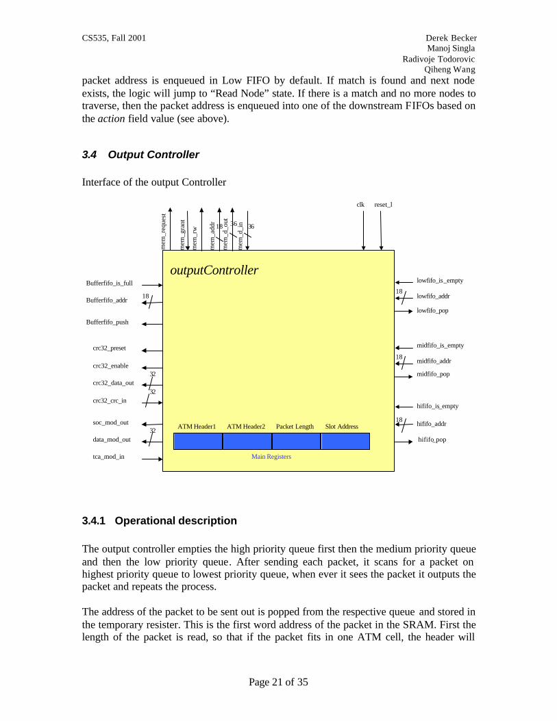
3.4 Output Controller Interface of the output Controller
3.4.1 Operational description The output controller empties the high priority queue first then the medium priority queue and then the low priority queue. After sending each packet, it scans for a packet on highest priority queue to lowest priority queue, when ever it sees the packet it outputs the packet and repeats the process. The address of the packet to be sent out is popped from the respective queue and stored in the temporary resister. This is the first word address of the packet in the SRAM. First the length of the packet is read, so that if the packet fits in one ATM cell, the header will
clk reset_l
Bufferfifo_is_full
Bufferfifo_addr
Bufferfifo_push
18
lowfifo_is_empty
lowfifo_addr
lowfifo_pop
18
midfifo_pop
hififo_addr
hififo_pop
18
midfifo_is_empty
hififo_is_empty
outputController
mem
_req
uest
mem
_rw
mem
_add
r
mem
_d_o
ut
mem
_d_i
n
mem
_gra
nt 18 3636
ATM Header1
midfifo_addr18
ATM Header2 Packet Length Slot Address
Main Registers
crc32_preset
crc32_data_out
crc32_enable
crc32_crc_in32
32
data_mod_out
soc_mod_out
tca_mod_in
32

CS535, Fall 2001 Derek Becker Manoj Singla Radivoje Todorovic Qiheng Wang
Page 22 of 35
have EOF bit one. The IP length read is converted in words i.e. right shift by 2 bits. It assumes that the length of packet is multiple of 4. The header in read next and stored in registers so that the same header can be transmitted for all the cells for this packet. The packet is read next and outputted in the cells. In the last cell for the packet, trailer is generated, as it is not stored with the packet. The trailer includes the CRC32 checksum and 16 bit length of the packet. The header of the last cell contains EOF from bit one.
ATM
H1
WORD
1
WORD
2
ATM
H2
… …
WORD
9
ATM
H1
WORD
1
WORD
2
ATM
H2
… …
WORD21
TRL
1
PAD
ATM
H1
WORD
1
WORD
2
ATM
H2
… …
WORD
9
TRL
2
… …ATM
H1
WORD
1
WORD
2
ATM
H2
WORD12
TRL
1
PAD
TRL
2
… …ATM
H1
WORD13
WORD14
ATM
H2
WORD
9
Sample Packet 1 in S R A M
Sample Packet 2 in S R A M
Only 1 cel l is send out as packet f i ts in one cel l
Two cel ls are send out as packet cannot f i t in 1 cel l
Simplified Bubble Diagram is given below:
CS535, Fall 2001 Derek Becker Manoj Singla Radivoje Todorovic Qiheng Wang
Page 23 of 35
Start
Header 1 & 2
Send address
lowfifomidfifohififo
Send data
Wait tca
Read LengthLast Word In cell
3.4.2 Interface: Output signals to SRAM arbiter mem_request -- Requesting memory access, active high. mem_rw -- 1- Read from memory, 0- write to memory mem_addr -- Address of memory where to read or write mem_data_out -- Data that is to be written to SRAM Input signals from SRAM arbiter mem_grant -- SRAM access granted, active high. mem_data_in -- Data from SRAM Input signals from data FIFO queues lowfifo_is_empty -- 1 – low priority queue is empty lowfifo_addr -- Address of the packet midfifo_is_empty -- 1 – medium priority queue is empty midfifo_addr -- Address of the packet hififo_is_empty -- 1 – high priority queue is empty hififo_addr -- Address of the packet Output signals to data FIFO queues lowfifo_pop -- Pop the current address of low queue midfifo_pop -- Pop the current address of medium queue hififo_pop -- Pop the current address of high queue

CS535, Fall 2001 Derek Becker Manoj Singla Radivoje Todorovic Qiheng Wang
Page 24 of 35
The pop signal should be high for only 1 clock cycle. Input signals from Free address queue BufferFIFO_is_full -- 1- queue is full so cannot put new address, this should not happen as the length of this queue should be same as the number of slots available in SRAM. Output signals to Free address queue BufferFIFO_addressIn -- Free address BufferFIFO_pushAddress -- 1- push the address from BufferFifo_addressIn onto queue. It should be high for 1 clock cycle only. Input signals from CRC32 module crc32_crc_in -- CRC32 checksum, available one clock cycle later than the input. Output signals to CRC32 module crc32_preset -- Start new CRC32 computation, active low crc32_enable -- 1- include current data in CRC32 calculation crc32_data_out –- CRC32 checksum Input signals tca_mod_in -- Tells the status of next node, 1- Send more cell, 0- do not send cells Output signals d_mod_out -- Data out soc_mod_out -- start of cell, 1- new cell started
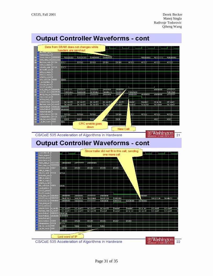
3.4.3 Implementation Details The output controller checks, which queue to take the packet from depending on the priority of the queue. The address of the packet is popped from the queue and request for memory read is sent to SRAM arbiter. SRAM arbiter schedules the memory request based on priority of the module. SRAM arbiter will notify as soon SRAM can be access. The length of the packet is read first to see if the packet can be packed in one cell. Now the packet is read from SRAM one word at a time. The headers are stored in registers as the same header will be used in all the cells belonging to this packet. The header 1 is sent out and at the same time start of cell signal is set to one so that the receiving side can know where the cell starts. If this is the last cell in the packet, 2nd LSB is set to one else it is zero. The data starts going out after the header 2. If the packet cannot fit in one cell, the reading of SRAM is synchronized so that when we want to output the header for the next

CS535, Fall 2001 Derek Becker Manoj Singla Radivoje Todorovic Qiheng Wang
Page 25 of 35
cell, we don’t receive the data from the memory. When outputting the header the CRC32 checksum enable signal is kept low so that the header is not included in CRC32 calculation. Padding has to be added in the last cell if the packet does not completely fit in the cell. There is no need to pad if the packet length (in words) is 12 * x + 10 –where x can be any positive number. The last two word of the last cell is the trailer. The trailer1 contains the length of the packet and the trailer 2 contains the CRC32 checksum. After the complete packet is sent out, the now free address is pushed onto the free queue, so that the Input controller can use it later. When the output circuit is busy or congested, it will stop sending the cells and pause until the output circuit is cleared and will continue from where it paused.
3.5 SRAM Arbiter The sramArbiter provides prioritized access to SRAM memory while attempting to maintain a fair distribution of access across all components. The sramArbiter achieves this goal by maintaining a simple state machine that controls a set of muxes to memory signals. When in the start state, the sramArbiter chooses the next requesting component to receive memory access based on the following priority:
1. TreeParser 2. TreeUpdate 3. Input 4. Output
When the component is selected, the muxes change to connect the component to a set of flops (to clock the memory signals) and then wait for the component to deassert the mem_req signal. The sramArbiter then returns to the start state.
3.6 Address FIFO The AddressFIFO component implements a simple FIFO for holding SRAM address pointers. By placing an address on the address_in signal while simultaneously asserting the push_address the address is placed at the end of the queue. If the pop_address signal is asserted then the address at the top of the queue is popped off and placed in address_out. For the purposes of our implementation we set the size of the FIFOs at 10 slots.
4 Testing and performance evaluation
4.1 Results The results of our implementation are very promising. While the hardware design is far from optimized, we were able to reduce simulated packet processing latency from 3µs to roughly 1.4µs. If we factor in the overhead of receiving and sending the packets, our

CS535, Fall 2001 Derek Becker Manoj Singla Radivoje Todorovic Qiheng Wang
Page 26 of 35
performance factor approaches 3 to 1. We strongly feel that further development of the hardware implementation would result in a faster design.
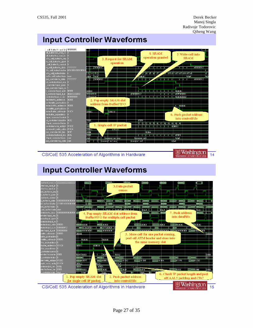
4.2 Simulation results All the components are carefully tested during the simulation and it was successful. Some of the highlights are given below
4.2.1 Input Controller Waveforms
CS535, Fall 2001 Derek Becker Manoj Singla Radivoje Todorovic Qiheng Wang
Page 27 of 35
CS535, Fall 2001 Derek Becker Manoj Singla Radivoje Todorovic Qiheng Wang
Page 28 of 35
4.2.2 Tree Update Waveforms
4.2.3 Tree Parser Waveforms
CS535, Fall 2001 Derek Becker Manoj Singla Radivoje Todorovic Qiheng Wang
Page 29 of 35

CS535, Fall 2001 Derek Becker Manoj Singla Radivoje Todorovic Qiheng Wang
Page 30 of 35
4.2.4 Output Controller Waveforms
CS535, Fall 2001 Derek Becker Manoj Singla Radivoje Todorovic Qiheng Wang
Page 31 of 35

CS535, Fall 2001 Derek Becker Manoj Singla Radivoje Todorovic Qiheng Wang
Page 32 of 35
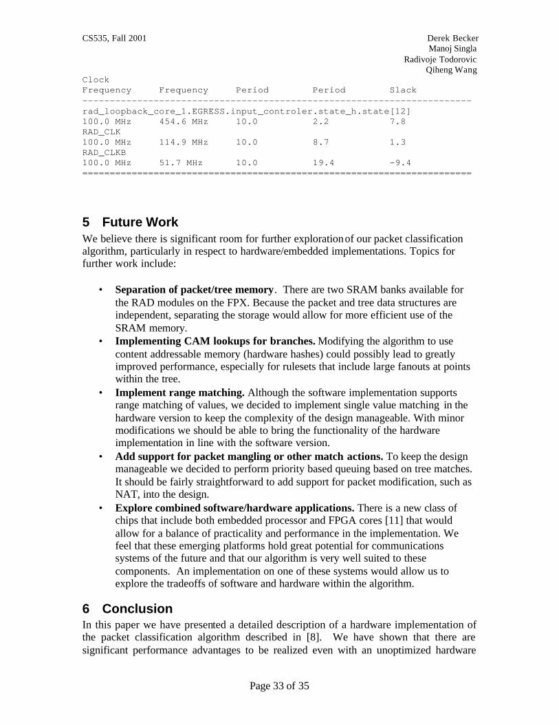
4.3 Synthesis results The synthesis of the design was somewhat disappointing. Primarily due to our lack of experience with high-performance VHDL design, we were able to initially achieve only a 30MHz maximum frequency for our implementation. However, we were able to redesign the components to utilize pipelining, improved logic and reduced flip-flop requirements to bring the critical path down to about 19.4ns, for a maximum clock frequency of 52MHz. We believe that further work on the design would eventually allow us to utilize the rated 100MHz clock of the FPX. Performance Summary ********************* Requested Estimated Requested Estimated
CS535, Fall 2001 Derek Becker Manoj Singla Radivoje Todorovic Qiheng Wang
Page 33 of 35
Clock Frequency Frequency Period Period Slack ----------------------------------------------------------------------- rad_loopback_core_1.EGRESS.input_controler.state_h.state[12] 100.0 MHz 454.6 MHz 10.0 2.2 7.8 RAD_CLK 100.0 MHz 114.9 MHz 10.0 8.7 1.3 RAD_CLKB 100.0 MHz 51.7 MHz 10.0 19.4 -9.4 =======================================================================
5 Future Work We believe there is significant room for further exploration of our packet classification algorithm, particularly in respect to hardware/embedded implementations. Topics for further work include:
• Separation of packet/tree memory. There are two SRAM banks available for the RAD modules on the FPX. Because the packet and tree data structures are independent, separating the storage would allow for more efficient use of the SRAM memory.
• Implementing CAM lookups for branches. Modifying the algorithm to use content addressable memory (hardware hashes) could possibly lead to greatly improved performance, especially for rulesets that include large fanouts at points within the tree.
• Implement range matching. Although the software implementation supports range matching of values, we decided to implement single value matching in the hardware version to keep the complexity of the design manageable. With minor modifications we should be able to bring the functionality of the hardware implementation in line with the software version.
• Add support for packet mangling or other match actions. To keep the design manageable we decided to perform priority based queuing based on tree matches. It should be fairly straightforward to add support for packet modification, such as NAT, into the design.
• Explore combined software/hardware applications. There is a new class of chips that include both embedded processor and FPGA cores [11] that would allow for a balance of practicality and performance in the implementation. We feel that these emerging platforms hold great potential for communications systems of the future and that our algorithm is very well suited to these components. An implementation on one of these systems would allow us to explore the tradeoffs of software and hardware within the algorithm.
6 Conclusion In this paper we have presented a detailed description of a hardware implementation of the packet classification algorithm described in [8]. We have shown that there are significant performance advantages to be realized even with an unoptimized hardware
CS535, Fall 2001 Derek Becker Manoj Singla Radivoje Todorovic Qiheng Wang
Page 34 of 35
implementation, and that future studies will likely increase performance. Although this particular implementation is targeted at the Field Programmable Port Extender [12], we have attempted to leave the parser and update components media independent by working at the frame level; both the algorithm and the implementation allow for matching Ethernet, AAL5, FR or other frame-oriented traffic. With further design and tuning this implementation should provide speed and flexibility comparable to or even exceeding current algorithms.
7 References [1] J. C. Mogul, R. F. Rashid, and M. J. Accetta.
The packet filter: An efficient mechanism for user-level network code. In Proceedings of SOSP, pages 39-51, Austin, TX, November 1987.
[2] Steven McCanne and Van Jacobson.
A BSD packet filter: A new architecture for user-level packet capture. In Proceedings of USENIX Winter Conference, pages 259-269, San Diego, CA, January 1993.
[3] Andrew Begel and Steven McCanne and Susan L. Graham Exploiting Global Data-Flow Optimization in a Generalized Packet Filter
Architecture In SIGCOMM ‘99, pages 123-134, Cambridge, MA, August, 1999 [4] M. L. Bailey, B. Gopal, P. Sarkar, M. A. Pagels, and L. L. Peterson,
"Pathfinder: A pattern-based packet classifier," In Proceedings of the 1st Symposium on Operating System Design and Implementation, USENIX Association, November 1994.
[5] M. Jayaram, R. K. Cytron, D. C. Schmidt, and G. Varghese,
"Efficient Demultiplexing of Network Packets by Automatic Parsing," In Submitted to the ACMSIGPLAN'95 Conference on ProgrammingLanguage Design and Implementation, ACM, 1994.
[6] The Bowman Active Networking OS Classifier:
http://www.cc.gatech.edu/projects/canes/odyssey/Odyssey.html#SEC62 http://www.cc.gatech.edu/projects/canes/software.html
[7] P. Gupta and N. McKeown,
"Packet classification on multiple fields," in Proceedings of ACM SIGCOMM'99, ACM, August 1999.
[8] D. Becker, R. Todorovic, Q. Wang “PTREE: A System for Flexible, Efficient Packet Classification,” CS524 Final Project http://www.cs.wustl.edu/~qwang/research/tbf_paper.doc

CS535, Fall 2001 Derek Becker Manoj Singla Radivoje Todorovic Qiheng Wang
Page 35 of 35
[9] David E. Taylor, John W Lockwood, Sarang Dharmapurikar, Generalized
RAD Module Interface Specification of the Field Programmable Port Extender (FPX), Washington University, Department of Computer Science. Version 2.0, Technical Report, January 8, 2000.
[10] C. M. Heard, CRC-32 Generator, http://cell-
relay.indiana.edu/mhonarc/cell-relay/1997-Aug/msg00040.html [11] QuickLogic QuickMIPS embedded communications processors,
http://www.quicklogic.com/home.asp?PageID=376&sMenuID=220 [12] Reprogrammable Network Packet Processing on the Field Programmable
Port Extender (FPX), by John W. Lockwood, Naji Naufel, Jon S. Turner, and David E. Taylor, ACM International Symposium on Field Programmable Gate Arrays (FPGA'2001), Monterey, CA, February 2001, pp. 87-93.