ptp 800 sales guid release 03-00
TRANSCRIPT
7/27/2019 PTP 800 Sales Guid Release 03-00
http://slidepdf.com/reader/full/ptp-800-sales-guid-release-03-00 1/36
1 of 36
Purpose and Scope
SALES GUIDES IDE
SALES GUIDE
PTP 800 – REL. 03-00LICENSED ETHERNETMICROWAVE
This Sales Guide is considered Motorola Confidential Proprietary. The purpose of thisSales Guide is to equip our account teams and authorized channel members with theinformation needed to effectively position and sell our Point-to-Point (PTP) 800Licensed Ethernet Microwave Solutions.
This is a living document that acts as a central point of reference regarding this release.To avoid information becoming out-of-date, this document may contain hyperlinks for access to other related sources of information. It is permissible to extract certainsections or subsections that apply to specific customer situations. However, thisdocument should not be used for contracts or proposals in lieu of an official Motorolacustomer document.

7/27/2019 PTP 800 Sales Guid Release 03-00
http://slidepdf.com/reader/full/ptp-800-sales-guid-release-03-00 2/36
2 of 36
KEY SELLING POINTS
Operating in the 6 to 38 GHz1
bands, the PTP 800 Licensed Ethernet Microwave solutions give enterprises,government organizations, service providers and carriers wi th high-capacity, reliable and affordableconnectivity for a w ide variety of public and private network applications.
•
Compelling reasons to purchase the PTP 800:o Adaptive Coding and Modulation (ACM) adjusts modulation to provide the best possible throughputand highest availability for the radio path conditions; links may also be configured with FixedModulation.
o Capacity-as-you-grow scalability allows you to purchase only the throughput capacity needed today andupgrade capacity as requirements increase.
o IP-based architecture initiates an easy, smooth migration path to an all-IP network.o PTP LINKPlanner tool lets you design and optimize link performance prior to purchase and provides a
detailed performance report.o PTP LINKPlanner also compiles a complete licensed-microwave Bill of Materials (BOM) to streamline the
purchasing process.o The scalability and pricing structure provide you with an affordable licensed microwave solution.
• With a PTP 800 licensed microwave link you can:
o Reduce or eliminate recurring fees by replacing or augmenting leased lineso Connect a headquarters location with a warehouse, service center, branch office or other facilityo Provide high-performance network redundancy for wired/fiber networkso Backhaul traffic from multiple LAN access points to a point of presenceo Extend video surveillance beyond the constraints of a wired network and backhaul traffic from video
surveillance cameraso Provide last-mile access and/or last-mile fiber extensionso Deliver additional capacity for wired networks and remove network bottleneckso Provide backhaul communications for a spur or secondary ring at the network edgeo Supply fast and cost-effective communications for disaster recovery and temporary serviceso Grow subscriber networks by establishing or improving services in underserved areas
• Why should you choose the PTP 800 solution?
o “Errorless and Hitless” ACM makes step changes without service interruption – many comparablesystems incur outages during switchover.
o Throughput scalability can reduce capital expenditures while providing exceptional flexibility to meettoday’s needs and future growth.
o PTP LINKPlanner’s automatic BOM simplifies the purchasing process and saves you time.o One Point Wireless provides a common set of design, deployment and management tools that simplify
wireless network management functions.o Complete Ethernet PTP portfolio lets you combine solutions to meet virtually any business, budget and
environmental needso We can provide FCC microwave license coordination services for a fee, if desired (in the U.S.)
More information about PTP 800 Series solutions is available at motorola.com/ptp
1PTP 800 models for the 6 to 38 GHz bands are available in a series of product releases.
7/27/2019 PTP 800 Sales Guid Release 03-00
http://slidepdf.com/reader/full/ptp-800-sales-guid-release-03-00 3/36
3 of 36
1.0 EXECUTIVE SUMMARY ........................................................................................................... 5
2.0 PRODUCT OVERVIEW ............................................................................................................. 6
2.1 PTP 800 03-00 RELEASE ..................................................................................................... 6
2.2 KEY FEATURES ................................................................................................................... 7
2.3 PTP 800 COMPONENTS .................................................................................................... 11
2.4 CAPACITY-AS-YOU-GROW THROUGHPUT .................................................................... 11
2.5 ASYMMETRIC THROUGHPUT CONTROL ....................................................................... 12
2.6 ADAPTIVE CODING AND MODULATION.......................................................................... 12
2.7 FAST ETHERNET SHUTDOWN (FES) AND LAYER 2 CONTROL PROTOCOL.............. 13
2.8 NETWORK MANAGEMENT ............................................................................................... 13
2.9 PTP LINKPLANNER............................................................................................................ 14
2.10 BAND PLAN ...................................................................................................................... 16
2.11 PTP 800 1+0 NON-REDUNDANT CONFIGURATION ..................................................... 18
2.12 PTP 800 1+1 HSB REDUNDANT CONFIGURATION ...................................................... 18
2.13 PTP 800 2+0 RING/MESH CONFIGURATION................................................................. 19
3.0 CONFIGURATION AND ORDERING ..................................................................................... 20
3.1 ORDERING THE PTP 800 .................................................................................................. 20
3.2 INSTALLATION ................................................................................................................... 21
4.0 PTP 800 SALES TOOLS ........................................................................................................ 24
4.1 MARKET OPPORTUNITY .................................................................................................. 24
4.2 PAIN – WHAT ARE THE NETWORK MANAGEMENT PRIORITIES? ............................... 25
4.3 VISION – WHAT CAN A PTP 800 SYSTEM DO? .............................................................. 26
4.4 BENEFITS – WHO BENEFITS FROM A PTP 800 PURCHASE DECISION? .................... 27
4.5 COMPETITION – THE PTP 800 VERSUS THE COMPETITION. ...................................... 29
4.6 OVERCOMING OBJECTIONS ........................................................................................... 30
5.0 FREQUENTLY ASKED QUESTIONS ..................................................................................... 31
APPENDIX: PTP 800 03-00 SPECIFICATIONS ........................................................................... 33
TABLE OF CONTENTS

7/27/2019 PTP 800 Sales Guid Release 03-00
http://slidepdf.com/reader/full/ptp-800-sales-guid-release-03-00 4/36
4 of 36
ACM Adaptive Coding and ModulationBOM Bill of MaterialsCMU Compact Modem UnitLOS Line-of-sight (clear line-of-sight and Fresnel zone is clear)
nLOS Near-line-of-sight (clear line-of-sight but Fresnel zone is blocked)NLOS Non-line-of-sight (no line-of-sight and Fresnel zone is blocked)NMS Network Management SystemODU Outdoor UnitPMP Point-to-MultipointPoE Power-over-EthernetPTP Point-to-PointQAM Quadrature Amplitude ModulationRF Radio FrequencySNMP Simple Network Management ProtocolXPIC Cross Polarization Interference Canceller
ACRONYM REFERENCES

7/27/2019 PTP 800 Sales Guid Release 03-00
http://slidepdf.com/reader/full/ptp-800-sales-guid-release-03-00 5/36
5 of 36
1.0 EXECUTIVE SUMMARY
THE OPPORTUNITY: MORE BANDWIDTH!
Bandwidth demand is being driven by the growth of multimedia applications that encompass voice, video anddata – with video-dominated content accounting for an ever-increasing percentage of the mix. In business andgovernment, voice and video is being used for everything from on-demand tutorials, video conferencing and
training to media relations, products demonstrations and video surveillance. Consumers also want access tohigher bandwidth applications such as online gaming, social networking and on-demand television. As a result,virtually all organizations are in the process of transitioning, or at least planning to transition, to a converged IP-based network. To compete in and service today’s and tomorrow’s markets, you need unified networks that arecapable of supplying adequate bandwidth to support the varied multimedia applications that your users andcustomers require.
THE SOLUTION: POINT-TO-POINT (PTP) 800 LICENSED ETHERNET MICROWAVE
PTP 800 Licensed Ethernet Microwave solutions are IP-optimized, high-capacity wireless broadband radiosdesigned to efficiently and affordably transport the data, voice and video that your high-bandwidth applicationsrequire. At the same time, our Ethernet-based PTP 800 solutions can help you start or advance a smoothmigration path to an IP-based network. Operating in the 6 to 38 GHz licensed bands with up to 368 Mbps full-duplex throughput
2
and user-configurable channel bandwidths from 7 to 56 MHz, PTP 800 systems can serve a
wide variety of enterprise, government, service provider and carrier applications. Plus, PTP 800 radios can bedeployed quickly, are easy to use and offer time-saving wireless network design and management capabilities.
WIRELESS NETWORK SOLUTIONSPTP 800 Licensed Ethernet Microwave solutions are included in our Wireless Network Solutions portfolio. Thisportfolio delivers seamless connectivity that puts real-time information in the hands of users, giving you theagility you need to grow your business or better protect and serve the public. Our unrivalled wireless networksolutions include indoor WLAN, outdoor wireless mesh, point-to-multipoint, point-to-point networks and voiceover WLAN solutions. Combined with powerful software for wireless network design, security, management andtroubleshooting, our solutions deliver trusted networking and anywhere access to organizations across theglobe.
2
The maximum throughput of 368 Mbps full duplex requires a 56 MHz channel and 256 QAM modulation which may not beavailable in certain regions due to regulatory restrictions.
PTP 800 ODU
PTP 800 CMU
PTP 800 ODU (Outdoor Unit) PTP 800 CMU (Compact Modem Unit)
7/27/2019 PTP 800 Sales Guid Release 03-00
http://slidepdf.com/reader/full/ptp-800-sales-guid-release-03-00 6/36
6 of 36
2.0 PRODUCT OVERVIEW
PTP 800 Licensed Microwave systems are the ideal solution when you need high-performance connectivity tosupport bandwidth-intensive applications on your network.
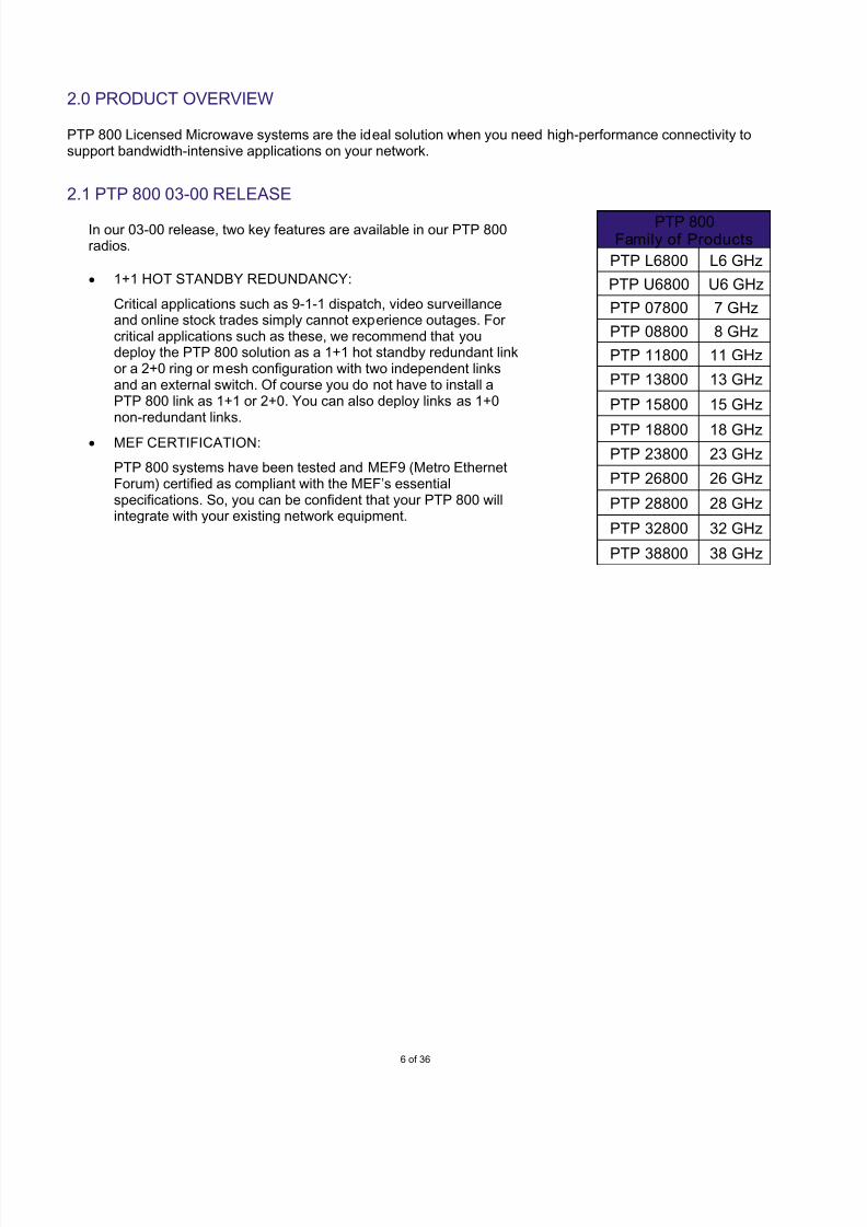
2.1 PTP 800 03-00 RELEASE
PTP 800Family of Products
PTP L6800 L6 GHz
PTP U6800 U6 GHz
PTP 07800 7 GHz
PTP 08800 8 GHz
PTP 11800 11 GHz
PTP 13800 13 GHz
PTP 15800 15 GHz
PTP 18800 18 GHzPTP 23800 23 GHz
PTP 26800 26 GHz
PTP 28800 28 GHz
PTP 32800 32 GHz
PTP 38800 38 GHz
In our 03-00 release, two key features are available in our PTP 800radios.
• 1+1 HOT STANDBY REDUNDANCY:
Critical applications such as 9-1-1 dispatch, video surveillanceand online stock trades simply cannot experience outages. For critical applications such as these, we recommend that youdeploy the PTP 800 solution as a 1+1 hot standby redundant linkor a 2+0 ring or mesh configuration with two independent linksand an external switch. Of course you do not have to install aPTP 800 link as 1+1 or 2+0. You can also deploy links as 1+0non-redundant links.
• MEF CERTIFICATION:
PTP 800 systems have been tested and MEF9 (Metro EthernetForum) certified as compliant with the MEF’s essentialspecifications. So, you can be confident that your PTP 800 willintegrate with your existing network equipment.

7/27/2019 PTP 800 Sales Guid Release 03-00
http://slidepdf.com/reader/full/ptp-800-sales-guid-release-03-00 7/36
7 of 36
2.2 KEY FEATURES
PTP 800 – HIGH-LEVEL FEATURE SET
High Throughput PTP 800 Series radios provide up to 368 Mbps full-duplex throughput(1518-byte frames @ 56 MHz channel):
• Throughput at the user Ethernet port is controlled by software key
• Links ship with a factory-set 10 Mbps throughput capacity cap
• Throughput capacity can be increased by purchasing a capacity-capupgrade at the time of order or anytime after deployment
• Capacity-cap upgrades are enabled via a software key and require nohardware change
Exceptional Scalabilit y • Capacity-as-you-grow throughput allows you to purchase only whatyou need now and increase throughput capacity as your needs grow.
• Single-step capacity upgrades can be purchased in the followingincrements:
X ► 20 Mbps (per unit)X ► 30 Mbps (per unit) X ► 40 Mbps (per unit)
X ► 50 Mbps (per unit) X ► 100 Mbps (per unit) X ► 150 Mbps (per unit) X ► 200 Mbps (per unit) X ► 300 Mbps (per unit) X ► Full Capacity – 368 Mbps (per unit)
• Flexible stepped upgrades give you great flexibility to matchthroughput requirements to applications and budget by upgrading insteps over some period of time:
10 ► 20 Mbps (per unit)20 ► 30 Mbps (per unit) 30 ► 40 Mbps (per unit) 40 ► 50 Mbps (per unit)
50 ► 100 Mbps (per unit)100 ► 150 Mbps (per unit) 150 ► 200 Mbps (per unit) 200 ► 300 Mbps (per unit) 300 ► Full Capacity – 368 Mbps (per unit)
Licensed RF Bands • PTP 800 bridges will support licensed bands from 6 to 38 GHz.
• Currently, all models are available except 28 and 32 GHz (ETSI):
• Subsequent releases will provide models for these frequencies.
• In all cases, local regulatory requirements should be confirmed prior tosystem purchase.
Low Latency To < 115 µs @368 Mbps with a 64-byte frame
AsymmetricThroughput Control
You can assign different throughput capacities for the up and down linksbased on your users’ traffic patterns.
Configurable Channel
Widths
PTP 800 systems provide user-configurable channel bandwidths from 7 to
56 MHz to match licensing regulations.
7/27/2019 PTP 800 Sales Guid Release 03-00
http://slidepdf.com/reader/full/ptp-800-sales-guid-release-03-00 8/36
8 of 36
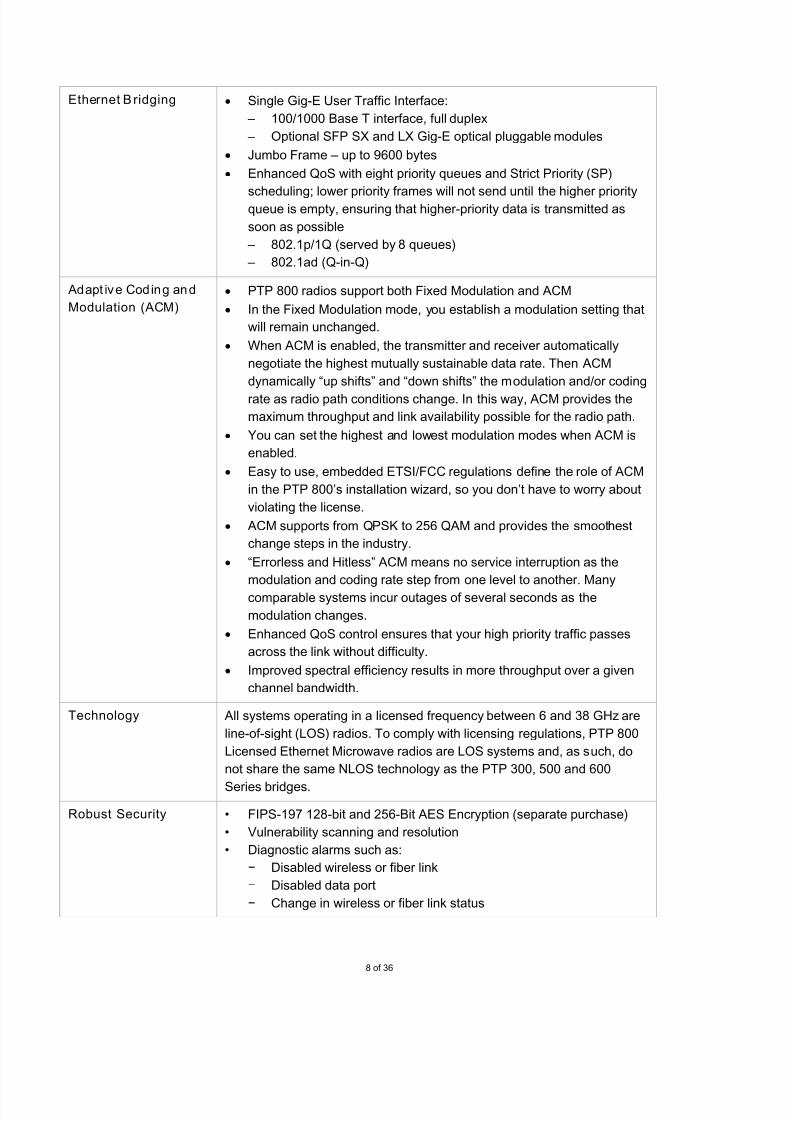
Ethernet Bridging • Single Gig-E User Traffic Interface:
– 100/1000 Base T interface, full duplex
– Optional SFP SX and LX Gig-E optical pluggable modules
• Jumbo Frame – up to 9600 bytes
• Enhanced QoS with eight priority queues and Strict Priority (SP)
scheduling; lower priority frames will not send until the higher priorityqueue is empty, ensuring that higher-priority data is transmitted as
soon as possible
– 802.1p/1Q (served by 8 queues)
– 802.1ad (Q-in-Q)
Adapt ive Coding and
Modulation (ACM)
• PTP 800 radios support both Fixed Modulation and ACM
• In the Fixed Modulation mode, you establish a modulation setting that
will remain unchanged.
• When ACM is enabled, the transmitter and receiver automatically
negotiate the highest mutually sustainable data rate. Then ACM
dynamically “up shifts” and “down shifts” the modulation and/or coding
rate as radio path conditions change. In this way, ACM provides the
maximum throughput and link availability possible for the radio path.
• You can set the highest and lowest modulation modes when ACM is
enabled.
• Easy to use, embedded ETSI/FCC regulations define the role of ACM
in the PTP 800’s installation wizard, so you don’t have to worry about
violating the license.
• ACM supports from QPSK to 256 QAM and provides the smoothest
change steps in the industry.
• “Errorless and Hitless” ACM means no service interruption as the
modulation and coding rate step from one level to another. Many
comparable systems incur outages of several seconds as the
modulation changes.
• Enhanced QoS control ensures that your high priority traffic passes
across the link without difficulty.
• Improved spectral efficiency results in more throughput over a given
channel bandwidth.
Technology All systems operating in a licensed frequency between 6 and 38 GHz are
line-of-sight (LOS) radios. To comply with licensing regulations, PTP 800
Licensed Ethernet Microwave radios are LOS systems and, as such, do
not share the same NLOS technology as the PTP 300, 500 and 600
Series bridges.
Robust Security • FIPS-197 128-bit and 256-Bit AES Encryption (separate purchase)
• Vulnerability scanning and resolution
• Diagnostic alarms such as:
− Disabled wireless or fiber link
− Disabled data port
− Change in wireless or fiber link status

7/27/2019 PTP 800 Sales Guid Release 03-00
http://slidepdf.com/reader/full/ptp-800-sales-guid-release-03-00 9/36
9 of 36
Robust Security
(continued)
− Change in TDD status
• “Save and restore” feature for disaster recovery
Redundancy • Systems support 1+0, 1+1 and 2+0 configurations
• 1+1 hot standby redundancy provides full redundancy in the event of a
single CMU or ODU failure at one or both ends of a link.
• You can also achieve redundancy with 2+0 configuration deployed in
a ring/mesh configuration with two independent links and an external
switch.
• 1+0 configurations are non-redundant links. If redundancy is desired
after deployment, you can upgrade to a 1+1 or 2+0 redundant link and
use your existing hardware.
System Architecture • PTP 800 systems are designed with a split-mount architecture whichincludes an Outdoor Unit (ODU) and a Compact Modem Unit (CMU).
• ODU and CMU are connected by a single IF cable.
• Where rack space is limited or non-existent, the CMU can be wall-mounted or even set on a table.
•
CMU is frequency and capacity independent and operates reliably intemperatures from -27° to 131° F (-33° to 55° C).
• ODU is frequency dependent and operates reliably in the same
temperature range as the CMU.
• A typical 1+0 non-redundant PTP 800 link includes:
− 2 CMUs with a software key for the desired throughput capacity
− 2 ODUs for the frequency desired
− 2 Antennas
− IF cables
− 2 Coaxial cable assembly kits
− 2 PTP 800 LPU kits
Link Planning The PTP LINKPlanner is a link design and optimization tool that is
available as a stand-alone tool or included in our One Point Wireless
portfolio, allowing you to:
• Perform calculations for both licensed and unlicensed PTP products
(currently excludes the PTP 100 and certain PTP 200 Series products)
• Plan and optimize a single link or multiple links simultaneously
• Accurately predict PTP link performance and set realistic expectations
• Display an overview of the wireless network via Google™ Earth
• Obtain a detailed performance report as a deployment guide
• Receive a complete PTP 800 licensed-microwave BOM to streamline
purchasing – a real time saver • Obtain a report that can be submitted to the licensing agent with
information needed to complete an FCC license application (available
only in the U.S.)
7/27/2019 PTP 800 Sales Guid Release 03-00
http://slidepdf.com/reader/full/ptp-800-sales-guid-release-03-00 10/36
10 of 36
Flexible Network
Management Options
• In-band and out-of-band management
• Remote management via Web browser
• Integrates with your existing NMS via SNMP v1/v2c, MIB-II, RFC-
1493, RFC-2233 MIB and our proprietary PTP MIB
• Use our Wireless Manager as your NMS (available in a future
Wireless Manager release)
12-Month Standard
Warranty
The purchase of a PTP 800 system includes a 12-month limited warranty
on hardware components with 30-day repair-and-return terms for
damaged parts, plus minor software enhancements as available and 24x7
telephone support. Each warranty must be registered online at
motorola.com/ptp to activate the free 12-month warranty period and
receive notification of software updates.
Extended Warranties At the time of purchase or anytime prior to the end of the 12-month
Standard Warranty, we recommend that you purchase an Extended
Warranty to obtain upgraded and/or extended equipment coverage.
Extended Warranty wi th All Risks Advanced Replacement: This
warranty upgrades and extends the initial 12-month Standard Warranty to
include All Risks equipment coverage with the Advanced Replacement
Program. The All Risks feature provides coverage for virtually all types of
equipment damage, including lightning, dropped units, vandalism, fire and
other types of damage. Under the Advanced Replacement program, units
are shipped from the UK3
the next business day after receipt of a
confirmed RMA, and we pay shipping costs in both directions. Actual
delivery times will depend on ship-to locations and customs. This warranty
program also includes minor software enhancements as they become
available and 24x7 telephone support. Options are available to upgrade
your first year’s Standard Warranty to All Risks Advanced Replacement
and to extend coverage beyond the first year for another one, two or four
years.
Extended Warranty w ith Repair-and-Return: This warranty extends your
initial 12-month Standard Warranty with 30-day repair-and-return terms
through the second, third or fifth years of ownership. The warranty
includes minor software enhancements as they become available and
24x7 telephone support. Typically, this option is chosen if one or more
spare units are purchased for use as replacement units.
More information on our warranty programs is available at
motorola.com/ptp.
3Based on the customer’s location, PTP 800 equipment may ship from a location other than the UK. The All Risks
Advanced Replacement Extended Warranty may not be available in all geographic regions.
7/27/2019 PTP 800 Sales Guid Release 03-00
http://slidepdf.com/reader/full/ptp-800-sales-guid-release-03-00 11/36
11 of 36
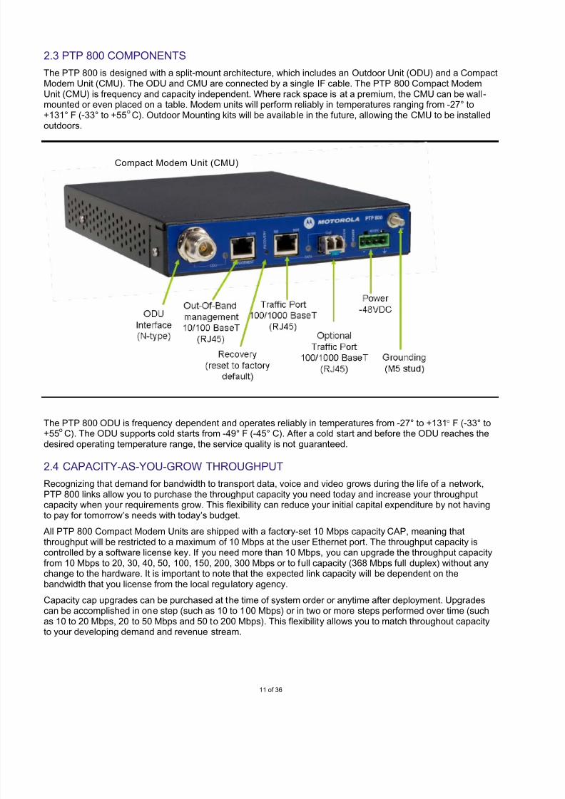
2.3 PTP 800 COMPONENTS
The PTP 800 is designed with a split-mount architecture, which includes an Outdoor Unit (ODU) and a CompactModem Unit (CMU). The ODU and CMU are connected by a single IF cable. The PTP 800 Compact ModemUnit (CMU) is frequency and capacity independent. Where rack space is at a premium, the CMU can be wall-mounted or even placed on a table. Modem units will perform reliably in temperatures ranging from -27° to+131° F (-33° to +55
oC). Outdoor Mounting kits will be available in the future, allowing the CMU to be installed
outdoors.
The PTP 800 ODU is frequency dependent and operates reliably in temperatures from -27° to +131° F (-33° to+55
oC). The ODU supports cold starts from -49° F (-45° C). After a cold start and before the ODU reaches the
desired operating temperature range, the service quality is not guaranteed.
2.4 CAPACITY-AS-YOU-GROW THROUGHPUT
Recognizing that demand for bandwidth to transport data, voice and video grows during the life of a network,PTP 800 links allow you to purchase the throughput capacity you need today and increase your throughputcapacity when your requirements grow. This flexibility can reduce your initial capital expenditure by not havingto pay for tomorrow’s needs with today’s budget.
All PTP 800 Compact Modem Units are shipped with a factory-set 10 Mbps capacity CAP, meaning thatthroughput will be restricted to a maximum of 10 Mbps at the user Ethernet port. The throughput capacity iscontrolled by a software license key. If you need more than 10 Mbps, you can upgrade the throughput capacity
from 10 Mbps to 20, 30, 40, 50, 100, 150, 200, 300 Mbps or to full capacity (368 Mbps full duplex) without anychange to the hardware. It is important to note that the expected link capacity will be dependent on thebandwidth that you license from the local regulatory agency.
Capacity cap upgrades can be purchased at the time of system order or anytime after deployment. Upgradescan be accomplished in one step (such as 10 to 100 Mbps) or in two or more steps performed over time (suchas 10 to 20 Mbps, 20 to 50 Mbps and 50 to 200 Mbps). This flexibility allows you to match throughout capacityto your developing demand and revenue stream.
Compact Modem Unit (CMU)
7/27/2019 PTP 800 Sales Guid Release 03-00
http://slidepdf.com/reader/full/ptp-800-sales-guid-release-03-00 12/36
12 of 36
When you purchase and activate a new throughput capacity-cap license key, the CMU will set the user Ethernetthroughput to the new throughput capacity cap without service interruption. PTP 800 links support throughputupgrade options only. No downgrades are available.
2.5 ASYMMETRIC THROUGHPUT CONTROL
PTP 800 systems can be configured with different download and upload throughput capacities. This is very
useful for carriers and service providers whose customers download information much more than they upload.In government and corporate enterprises, asymmetric throughput control is valuable for IP-based applicationssuch as video surveillance, product demonstrations, training, executive briefings and other activities whereusers are primarily receiving and viewing information. PTP LINKPlanner will allow you to model asymmetricdata flow and orchestrate the desired balance between downstream and upstream throughput.
When configuring your PTP 800 link with asymmetric control, each CMU can have its own throughput capacitycap. As an example, if you had a video surveillance link between a bank ATM and the bank’s security controlcenter, the CMU at the ATM video-camera end of the link might have a 200 Mbps capacity cap to transmitstreaming video to the security center. However, the CMU at the security control center might have a 10 Mbpscapacity cap because it is mostly receiving information and transmitting little data back to the video camera. Inthis case, the bank could reduce its capital expenditure by not having to purchase 200 Mbps throughputcapacity at the security center’s end of the link.
2.6 ADAPTIVE CODING AND MODULATION
For microwave link design, fade margin is always calculated with respect to transmit power and the receiver threshold level for a given Bit-Error Rate (BER), channel bandwidth and desired modulation mode. The radiowill meet expected performance and handle anything that affects the radio signal within the fade margin.However, when the radio exceeds the desired fade margin, a radio link without Adaptive Coding and Modulation(ACM) could go down and become unavailable.
PTP 800 radios support both Fixed Modulation and ACM. In the Fixed Modulation mode, you establish amodulation setting that will remain unchanged. When ACM is chosen, the ACM feature will enable thetransmitter and receiver to negotiate the highest mutually sustainable data rate and dynamically “up shift” and“down shift” the rate as radio path conditions change to provide the maximum throughput possible for the radiopath.
When a link’s Signal to Noise Ratio (SNR) is high, typically during good weather conditions, the radio will “upshift” to a higher modulation level and/or higher coding rate to improve the spectral efficiency and provide moreend-user throughput. Conversely, when the link’s SNR value falls below a threshold, typically during heavy rain,the radio will “down shift” to a lower modulation level and/or lower coding rate. Because of the improvement inreceive sensitivity and transmit power, the link budget will be improved, and the link will continue to operate.With Adaptive Modulation and enhanced QoS control, high-priority traffic (such as voice or real-time services)will still pass the link while only low priority traffic is dropped during the rain fade event.
The PTP 800’s ACM supports from QPSK to 256 QAM and provides exceptionally smooth throughput changesteps from one level to the next. The benefits of ACM include:
• Virtually no service interruption – errorless modulation and coding changes
• Improved spectral efficiency, resulting in more throughput over a given channel bandwidth
•Improved link availability during severe link degradation
• More modulation steps and the most smooth step changes in the industry
• Enhanced QoS control to ensure that high priority traffic is not impacted during link fading
Typically, other vendors’ products need several seconds to adjust the modulation mode which causes outagesto switch from one modulation mode to another. In the PTP 800, we use a Hitless algorithm with zero down time
– similar to the technology that has been widely used in the PTP 300, 500 and 600 Series products.
7/27/2019 PTP 800 Sales Guid Release 03-00
http://slidepdf.com/reader/full/ptp-800-sales-guid-release-03-00 13/36
13 of 36
The Adaptive Modulation in PTP 800 bridges will shift through eight modulation profiles from QPSK to 256QAM. Each modulation profile has approximately a 3 dB interval on the link budget. The shift of modulationprofile is extremely fast and can cope with channel fades up to 100 dB per second. As an example, let’sconsider a radio planned for 100 Mbps using a 28 MHz channel with 32 QAM. On a sunny day, the radio’s
Adaptive Modulation capability will “up shift” to 256 QAM with 180 Mbps throughput available to you. When thereceived SNR falls below the threshold, the system will preemptively “down shift” to 128 QAM, and your throughput will change to 156 Mbps. If the weather turns stormy, fade intensifies and the link budget is notsufficient to maintain 128 QAM, the radio may “down shift” to a more robust lower modulation.
For a link designed with 99.999% availability, the downtime for the link in a year could be five minutes. With ACM, a PTP 800 radio can “down shift” step-by-step and reach QPSK during extreme conditions, extending thelink availability beyond 99.999%. With ACM and the PTP 800’s enhanced QoS control, high priority voice anddata traffic will not be impacted even during severe weather conditions. When using Adaptive Modulation, thePTP 800 maximizes the spectral efficiency and improves link capacity and availability, while enabling you tosignificantly reduce your CAPEX.
2.7 FAST ETHERNET SHUTDOWN (FES) AND LAYER 2 CONTROL PROTOCOLCLASSIFICATION
PTP 800 radios can recognize all bridge frames as well as Generic Attribute Registration Protocol (GARP) and
Multiple Registration Protocol (MRP) frames. You can prioritize these frames using the PTP 800’s enhancedQuality of Service (QoS) control which has eight priority levels. In addition, the PTP 800 supports FES features.When you enable FES, the PTP 800 will shutdown the Ethernet port at both ends of a link within 50 ms should aradio link failure occur in either direction. With the PTP 800’s Layer 2 control protocol classification support andFES feature operating together with ITU-G.8032 or Rapid Spanning Tree Protocol (RSTP), you can achieve thelowest possible switch-over time in a Ring/Mesh configuration and enable faster traffic re-routing.
2.8 NETWORK MANAGEMENT
PTP 800 systems offer extremely flexible and user-friendly network management options including remotemanagement via Web browser, our Wireless Manager and the ability to integrate with your existing networkmanagement system via:
• SNMP v1, v2c
• Private and enterprise MIBs:o MIB-II, RFC-1213
o Bridge MID, RFC-1493
o RFC-2233 MIB
o PTP proprietary MIB
Our One Point Wireless portfolio offers a comprehensive suite of software solutions that simplify the design,deployment and management of wireless networks. From a single computer, you can plan, configure, monitor and manage your wireless network from inception through ongoing operations. The suite includes powerfulcomponents: PTP LINKPlanner, BroadbandPlanner, LANPlanner and Wireless Manager. With WirelessManager’s powerful visualization capabilities and advanced configuration, provisioning, alerting and reportingfeatures, you can control the network and achieve optimal system-wide performance and enhanced end-user satisfaction. In seconds, you can visualize virtually every detail of the network in real time on a single screen. Afuture release of Wireless Manager will support PTP 800 solutions.
7/27/2019 PTP 800 Sales Guid Release 03-00
http://slidepdf.com/reader/full/ptp-800-sales-guid-release-03-00 14/36
14 of 36
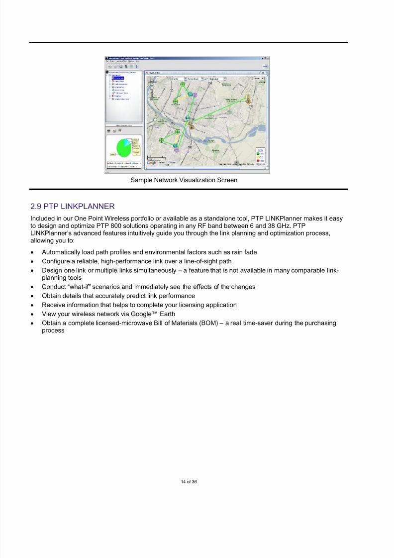
2.9 PTP LINKPLANNER
Included in our One Point Wireless portfolio or available as a standalone tool, PTP LINKPlanner makes it easyto design and optimize PTP 800 solutions operating in any RF band between 6 and 38 GHz. PTPLINKPlanner’s advanced features intuitively guide you through the link planning and optimization process,allowing you to:
• Automatically load path profiles and environmental factors such as rain fade
• Configure a reliable, high-performance link over a line-of-sight path
• Design one link or multiple links simultaneously – a feature that is not available in many comparable link-planning tools
• Conduct “what-if” scenarios and immediately see the effects of the changes
• Obtain details that accurately predict link performance
• Receive information that helps to complete your licensing application
• View your wireless network via Google™ Earth
• Obtain a complete licensed-microwave Bill of Materials (BOM) – a real time-saver during the purchasingprocess
Sample Network Visualization Screen

7/27/2019 PTP 800 Sales Guid Release 03-00
http://slidepdf.com/reader/full/ptp-800-sales-guid-release-03-00 15/36
15 of 36
Sample PTP 800 Path Profile
7/27/2019 PTP 800 Sales Guid Release 03-00
http://slidepdf.com/reader/full/ptp-800-sales-guid-release-03-00 16/36
16 of 36
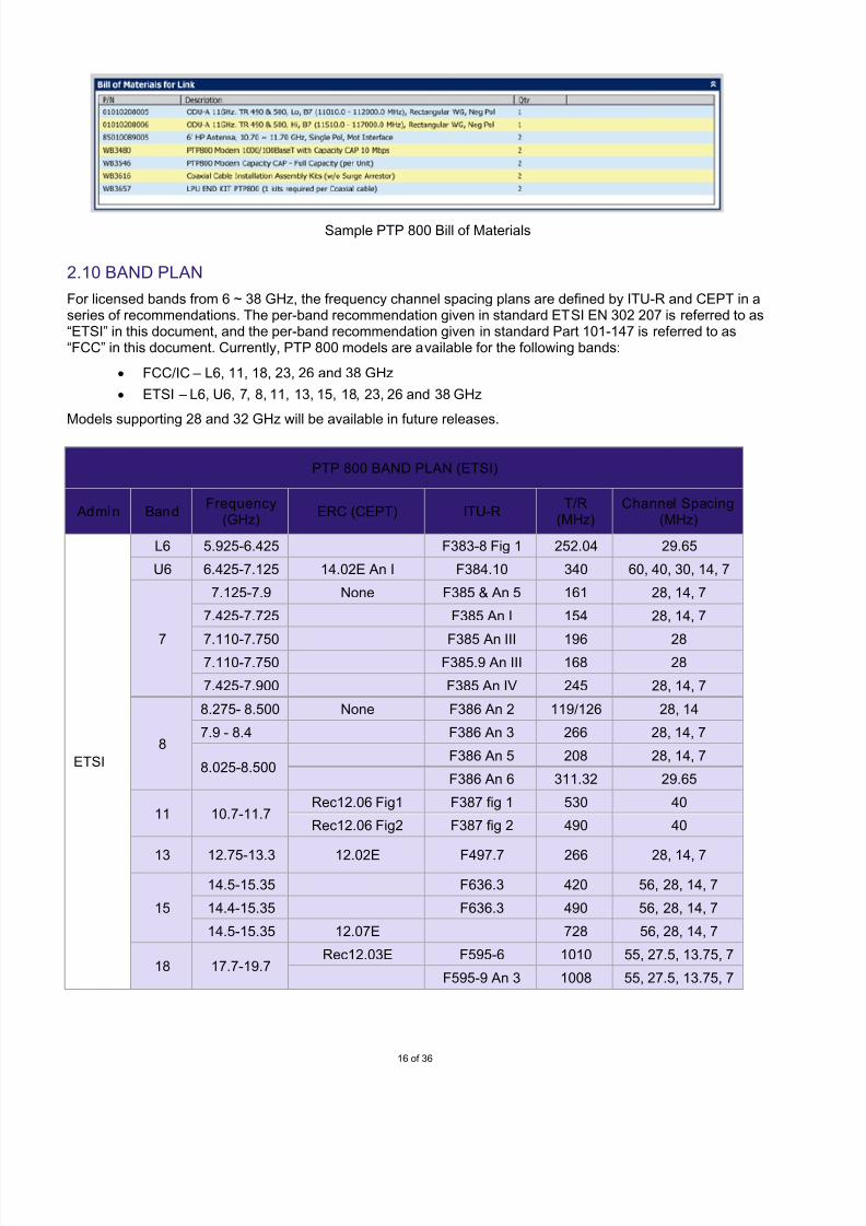
Sample PTP 800 Bill of Materials
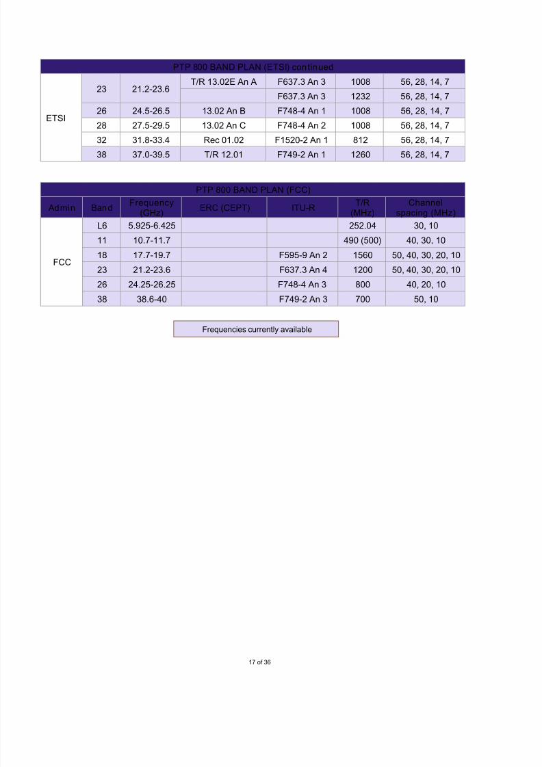
2.10 BAND PLAN
For licensed bands from 6 ~ 38 GHz, the frequency channel spacing plans are defined by ITU-R and CEPT in aseries of recommendations. The per-band recommendation given in standard ETSI EN 302 207 is referred to as“ETSI” in this document, and the per-band recommendation given in standard Part 101-147 is referred to as“FCC” in this document. Currently, PTP 800 models are available for the following bands:
• FCC/IC – L6, 11, 18, 23, 26 and 38 GHz
• ETSI – L6, U6, 7, 8, 11, 13, 15, 18, 23, 26 and 38 GHz
Models supporting 28 and 32 GHz will be available in future releases.
PTP 800 BAND PLAN (ETSI)
Admin BandFrequency
(GHz)ERC (CEPT) ITU-R
T/R(MHz)
Channel Spacing(MHz)
ETSI
L6 5.925-6.425 F383-8 Fig 1 252.04 29.65
U6 6.425-7.125 14.02E An I F384.10 340 60, 40, 30, 14, 7
7
7.125-7.9 None F385 & An 5 161 28, 14, 7
7.425-7.725 F385 An I 154 28, 14, 7
7.110-7.750 F385 An III 196 287.110-7.750 F385.9 An III 168 28
7.425-7.900 F385 An IV 245 28, 14, 7
8
8.275- 8.500 None F386 An 2 119/126 28, 14
7.9 - 8.4 F386 An 3 266 28, 14, 7
8.025-8.500F386 An 5 208 28, 14, 7
F386 An 6 311.32 29.65
11 10.7-11.7Rec12.06 Fig1 F387 fig 1 530 40
Rec12.06 Fig2 F387 fig 2 490 40
13 12.75-13.3 12.02E F497.7 266 28, 14, 7
15
14.5-15.35 F636.3 420 56, 28, 14, 7
14.4-15.35 F636.3 490 56, 28, 14, 7
14.5-15.35 12.07E 728 56, 28, 14, 7
18 17.7-19.7Rec12.03E F595-6 1010 55, 27.5, 13.75, 7
F595-9 An 3 1008 55, 27.5, 13.75, 7
7/27/2019 PTP 800 Sales Guid Release 03-00
http://slidepdf.com/reader/full/ptp-800-sales-guid-release-03-00 17/36
17 of 36
PTP 800 BAND PLAN (ETSI) cont inued
ETSI
23 21.2-23.6T/R 13.02E An A F637.3 An 3 1008 56, 28, 14, 7
F637.3 An 3 1232 56, 28, 14, 7
26 24.5-26.5 13.02 An B F748-4 An 1 1008 56, 28, 14, 7
28 27.5-29.5 13.02 An C F748-4 An 2 1008 56, 28, 14, 7
32 31.8-33.4 Rec 01.02 F1520-2 An 1 812 56, 28, 14, 7
38 37.0-39.5 T/R 12.01 F749-2 An 1 1260 56, 28, 14, 7
PTP 800 BAND PLAN (FCC)
Admin BandFrequency
(GHz)ERC (CEPT) ITU-R
T/R(MHz)
Channelspacing (MHz)
FCC
L6 5.925-6.425 252.04 30, 10
11 10.7-11.7 490 (500) 40, 30, 10
18 17.7-19.7 F595-9 An 2 1560 50, 40, 30, 20, 10
23 21.2-23.6 F637.3 An 4 1200 50, 40, 30, 20, 10
26 24.25-26.25 F748-4 An 3 800 40, 20, 10
38 38.6-40 F749-2 An 3 700 50, 10
Frequencies currently available

7/27/2019 PTP 800 Sales Guid Release 03-00
http://slidepdf.com/reader/full/ptp-800-sales-guid-release-03-00 18/36
18 of 36
2.11 PTP 800 1+0 NON-REDUNDANT CONFIGURATION
When deploying a 1+0 non-redundant link, you can install the equipment in a direct mount or remote mountconfiguration as shown below. 1+0 non-redundant links are excellent solutions for applications where you wouldnot incur significant consequences in the event of a hardware failure and subsequent communication outage.Should you deploy a non-redundant link and later want to achieve redundancy, you can easily upgrade your linkto 1+1 or 2+0 and continue to use your existing equipment
2.12 PTP 800 1+1 HSB REDUNDANT CONFIGURATION
In a 1+1 configuration, you will install two ODUs and two CMUs at each end of the link. If a hardware failureoccurs the secondary unit will automatically take control of the communications until repairs are completed. Inthis configuration, your ODUs can share the same antenna or be deployed with two antennas.
1+0 Direct Mount 1+0 Remote Mount
1+1 Direct Mount 1+1 Remote Mount

7/27/2019 PTP 800 Sales Guid Release 03-00
http://slidepdf.com/reader/full/ptp-800-sales-guid-release-03-00 19/36
19 of 36
2.13 PTP 800 2+0 RING/MESH CONFIGURATION
Because 2+0 systems are deployed with two independent links, this configuration can provide hardwareredundancy plus added throughput capacity. In 2+0 configurations, you need to supply your own externalswitch. The Ring/Mesh architecture requires N+1 links to achieve redundant link diversity for each location. Thisconfiguration can lower your network cost as compared with the 1+1 Hot Standby architecture which requiresequipment for two radio links in each location.
The benefits of using a Ring/Mesh configuration include:
•Lower equipment cost for a network with multiple nodes when compared with 1+1 Hot Standby
• Reduced hop length which can mean reduced antenna size
• Diversified link path which eliminates path fade issues when compared with 1+1 Hot Standby
• Easy and flexible options for network expansion
The drawbacks for a Ring/Mesh configuration include:
• Requires a higher capacity link because of link aggregation• Switch-over time for traffic re-routing

7/27/2019 PTP 800 Sales Guid Release 03-00
http://slidepdf.com/reader/full/ptp-800-sales-guid-release-03-00 20/36
20 of 36
3.0 CONFIGURATION AND ORDERING
3.1 ORDERING THE PTP 800
There are several key issues involved in configuring and ordering a PTP 800 system.
STEP 1: PLAN AND OPTIMIZE LINKS
To begin, you should complete a site survey. Both a physical and a radio-frequency analysis of the area
should be conducted to evaluate:• Availability and height of antenna-supporting structures,
• Existence of foliage and other obstructions,
• Environmental and seasonal issues,
• Spectrum analysis for the path at desired and alternate frequencies
• Anticipated changes in path conditions.
Then you can use the PTP LINKPlanner tool to plan and optimize a single link or multiple links based onyour specific applications and path requirements. PTP LINKPlanner greatly decreases the amount of timerequired to accurately predict PTP 800 link performance prior to purchase given certain assumptions aboutgeography, distance, antenna height, transmit power and other factors. By changing input data, you canconduct “what if’ scenarios and instantly see the effect on performance. For example, if a link calculation
projects low throughput, then a number of factors can be changed to improve throughput. You’re your haveoptimized the link to meet your requirements, LINKPlanner will provide vital information that can be given toyour licensing agent to assist in completing the licensing application
Note: Path calculations for PTP 800 systems can be performed only with the PTP LINKPlanner. For thatreason, you will want to attend one of the scheduled live or on-demand recorded tutorials to begin using thistool as soon as possible. You can obtain a schedule of live sessions and register for a session atmotorola.com/ptp.
STEP 2: IDENTIFY AVAILABLE LICENSED FREQUENCIES
After a PTP 800 system is configured, you will need to contact a local licensing agent for assistance indetermining the RF bands available. The licensing agent will survey existing license holders to determine if the customer’s desired band will conflict with any of the existing licenses. When none of the license holdersobjects, you can apply for the license in the desired RF band.
STEP 3: RECEIVE YOUR LICENSE OR PCN (PRIOR COORDINATION NOTIFICATION)
After applying for your license, you will receive your license or PCN. It is important to note that you shouldnot order your PTP 800 equipment until you have confirmation from your local regulatory agency indicatingthe frequency under which you will be operating. That way you will not order the wrong link components.
STEP 4: CONFIGURE YOUR LINK AND OBTAIN A BOM
After you have confirmation of the license frequency, use PTP LINKPlanner to configure your link. Once thelink is configured to your requirements, the system will provide a detailed performance report that can beused to guide your installers through a speedy deployment. Simultaneously, LINKPlanner compiles acomplete licensed-microwave Bill of Materials (BOM) to streamline the purchasing process.
STEP 5: ORDER YOUR PTP 800 SYSTEM
At this point, you can order your PTP 800 system using the BOM supplied by LINKPlanner. A typical order will include many components for each link being ordered. All CMU’s are factory configured with a 10-Mbpsthroughput capacity cap. However, the modem units will support throughput speeds from 10 Mbps to fullcapacity (368 Mbps full duplex). The user Ethernet-port throughput is controlled by a software license key,so CMU’s can be upgraded to 20, 30, 40, 50, 100, 150, 200, 300 Mbps or full capacity at order time or anytime after shipment and deployment.

7/27/2019 PTP 800 Sales Guid Release 03-00
http://slidepdf.com/reader/full/ptp-800-sales-guid-release-03-00 21/36
21 of 36
3.2 INSTALLATION
When ordering PTP 800 links, there are a few installation issues that need to be addressed to ensure that your order contains all the materials you will need for deployment. It is important to remember that the antenna mustbe fitted with a PTP 800 ODU proprietary interface as shown in the following illustrations.
DIRECT MOUNT 1+0
In a direct mount configuration, the ODU is attached via clips directly to the antenna which is fitted with aMotorola ODU interface.
POLARIZATION
6 and 11-32 GHz: Polarization depends on the antenna waveguide position. To change polarization, refer to theantenna installation procedure. The ODU rectangular waveguide interface must always be in alignment with theantenna waveguide input/output.
7, 8 and 38 GHz: Polarization depends only on the ODU position. For vertical polarization, make sure the arrow
on the ODU cover is vertical. For horizontal polarization, turn the ODU 90 degrees.
Horizontal Polarization Vertical Polarization

7/27/2019 PTP 800 Sales Guid Release 03-00
http://slidepdf.com/reader/full/ptp-800-sales-guid-release-03-00 22/36
22 of 36
REMOTE MOUNT 1+0
For a remote mount configuration, the ODU is attached to the pole with an ODU Remote Mount Kit (RMK), anda waveguide is required to connect with the antenna.
ODU COUPLER MOUNTING KIT
An ODU coupler-mounting kit is required for a 1+1 or 2+0 configuration (two links sharing the same antenna butrunning on different channels). The ODU coupler mounting kit supports direct mounting, using an Andrew-customized single-polarization antenna with a Motorola interface.
The ODU coupler mounting kit can also be remote mounted with the ODU remote mounting kit. Two differentcouplers are available: Symmetric 3 dB coupler and Asymmetric 6 dB coupler.
7/27/2019 PTP 800 Sales Guid Release 03-00
http://slidepdf.com/reader/full/ptp-800-sales-guid-release-03-00 23/36
23 of 36
CABLE INSTALLATION
A single IF coaxial cable is used to connect the ODU to the CMU:
• Up to 190 meters (623 ft): Andrew CNT400 cable or equivalent
• Up to 300 meters (984 ft): LMR600 cable or equivalent
Andrew CNT400 braided cable with the cable assembly kit and lightning protection kit can be ordered directlyfrom Motorola. The cable assembly kit includes:
• 1 x ODU Grounding Cable – 800 mm (Andrew GND-PTP 800)
• 2 x LPU grounding cable - 800 mm (Andrew GND-PTP 800)
• 1 x ODU to LPU Cable – 700 mm (Andrew C195-NMNM-M5)
• 2 x Cable Grounding Kit (Andrew 223158-2)
• 4 x N-type Connectors for the drop cable (Andrew 400PNM-CS8)
• 1 x Vinyl Insulating Tape and 1 x Self Amalgamating tape (Andrew WK-CNT)
• 50 x Tie Wraps (Andrew 40417)
• 1 x Instruction Sheet
• 1 x Packing List
The Polyphaser BGXZ series Lightning Protection Unit (LPU) is recommended for a PTP 800 installation. TheLPU kit includes:
• 2 x Polyphaser BGXZ surge protection unit
• 1 x Mounting kit for the surge protection unit
7/27/2019 PTP 800 Sales Guid Release 03-00
http://slidepdf.com/reader/full/ptp-800-sales-guid-release-03-00 24/36
24 of 36
4.0 PTP 800 SALES TOOLS
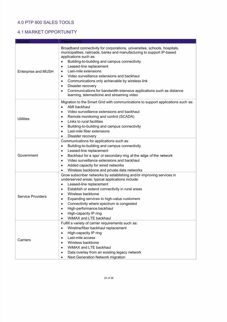
4.1 MARKET OPPORTUNITY
Market Opportunity
Enterprise and MUSH
Broadband connectivity for corporations, universities, schools, hospitals,municipalities, railroads, banks and manufacturing to support IP-based
applications such as:• Building-to-building and campus connectivity
• Leased-line replacement
• Last-mile extensions
• Video surveillance extensions and backhaul
• Communications only achievable by wireless link
• Disaster recovery
• Communications for bandwidth-intensive applications such as distancelearning, telemedicine and streaming video
Utilities
Migration to the Smart Grid with communications to support applications such as:
• AMI backhaul
•Video surveillance extensions and backhaul
• Remote monitoring and control (SCADA)
• Links to rural facilities
• Building-to-building and campus connectivity
• Last-mile fiber extensions
• Disaster recovery
Government
Communications for applications such as:
• Building-to-building and campus connectivity
• Leased-line replacement
• Backhaul for a spur or secondary ring at the edge of the network
• Video surveillance extensions and backhaul
• Added capacity for wired networks
• Wireless backbone and private data networks
Service Providers
Grow subscriber networks by establishing and/or improving services inunderserved areas; typical applications include:
• Leased-line replacement
• Establish or extend connectivity in rural areas
• Wireless backbone
• Expanding services to high-value customers
• Connectivity where spectrum is congested
• High-performance backhaul
• High-capacity IP ring
• WiMAX and LTE backhaul
Carriers
Fulfill a variety of carrier requirements such as:
• Wireline/fiber backhaul replacement
• High-capacity IP ring
• Last-mile access
• Wireless backbone
• WiMAX and LTE backhaul
• Data overlay from an existing legacy network
• Next Generation Network migration

7/27/2019 PTP 800 Sales Guid Release 03-00
http://slidepdf.com/reader/full/ptp-800-sales-guid-release-03-00 25/36
25 of 36
4.2 PAIN – WHAT ARE THE NETWORK MANAGEMENT PRIORITIES?
The need for a PTP 800 solution may be directly tied to a specific plan, priority, goal or initiative. One way toidentify these initiatives is to discuss the relative priority of the following areas of your customer’s network:critical priority, high priority, medium priority, low priority or no priority. Admitting a priority in any of these areasopens a discussion about managing the network and the need for a PTP 800 solution.
• Replacing or extending leased lines
• Supplying more bandwidth
• Attracting and serving new customers
• Eliminating or greatly reducing interference
• Offering expanded services
• Providing network redundancy
• Migrating to an IP-based infrastructure
• Provisioning, configuring and managing the wireless network
• Securing the network
7/27/2019 PTP 800 Sales Guid Release 03-00
http://slidepdf.com/reader/full/ptp-800-sales-guid-release-03-00 26/36
26 of 36
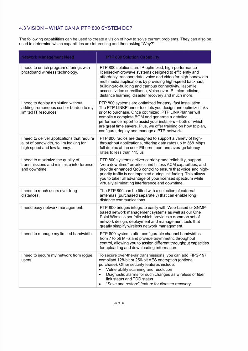
4.3 VISION – WHAT CAN A PTP 800 SYSTEM DO?
The following capabilities can be used to create a vision of how to solve current problems. They can also beused to determine which capabilities are interesting and then asking “Why?”
Network Management Need PTP 800 Solut ion Capabili ty
I need to enrich program offerings withbroadband wireless technology.
PTP 800 solutions are IP-optimized, high-performancelicensed-microwave systems designed to efficiently andaffordably transport data, voice and video for high-bandwidthmultimedia applications by providing high-speed backhaul,building-to-building and campus connectivity, last-mileaccess, video surveillance, Voice-over-IP, telemedicine,distance learning, disaster recovery and much more.
I need to deploy a solution withoutadding tremendous cost or burden to mylimited IT resources.
PTP 800 systems are optimized for easy, fast installation.The PTP LINKPlanner tool lets you design and optimize linksprior to purchase. Once optimized, PTP LINKPlanner willcompile a complete BOM and generate a detailed
performance report to assist your installers – both of whichare great time savers. Plus, we offer training on how to plan,configure, deploy and manage a PTP network.
I need to deliver applications that requirea lot of bandwidth, so I’m looking for high speed and low latency.
PTP 800 radios are designed to support a variety of high-throughput applications, offering data rates up to 368 Mbpsfull duplex at the user Ethernet port and average latencyrates to less than 115 µs.
I need to maximize the quality of transmissions and minimize interferenceand downtime.
PTP 800 systems deliver carrier-grade reliability, support“zero downtime” errorless and hitless ACM capabilities, andprovide enhanced QoS control to ensure that voice and high-priority traffic is not impacted during link fading. This allowsyou to take full advantage of your licensed spectrum while
virtually eliminating interference and downtime.I need to reach users over longdistances.
The PTP 800 can be fitted with a selection of externalantennas (purchased separately) that can enable longdistance communications.
I need easy network management. PTP 800 bridges integrate easily with Web-based or SNMP-based network management systems as well as our OnePoint Wireless portfolio which provides a common set of network design, deployment and management tools thatgreatly simplify wireless network management.
I need to manage my limited bandwidth. PTP 800 systems offer configurable channel bandwidthsfrom 7 to 56 MHz and provide asymmetric throughputcontrol, allowing you to assign different throughput capacitiesfor uploading and downloading information.
I need to secure my network from rogueusers.
To secure over-the-air transmissions, you can add FIPS-197compliant 128-bit or 256-bit AES encryption (optionalpurchase). Other security features include:
• Vulnerability scanning and resolution
• Diagnostic alarms for such changes as wireless or f iber link status and TDD status
• “Save and restore” feature for disaster recovery
7/27/2019 PTP 800 Sales Guid Release 03-00
http://slidepdf.com/reader/full/ptp-800-sales-guid-release-03-00 27/36
27 of 36
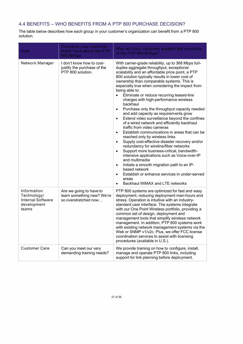
4.4 BENEFITS – WHO BENEFITS FROM A PTP 800 PURCHASE DECISION?
The table below describes how each group in your customer’s organization can benefit from a PTP 800solution.
RoleConcerns your customer might have about the PTP800 Bridge.
Why will your customer support the purchaseof the PTP 800 Bridge?
Network Manager I don’t know how to cost- justify the purchase of thePTP 800 solution.
With carrier-grade reliability, up to 368 Mbps full-duplex aggregate throughput, exceptionalscalability and an affordable price point, a PTP800 solution typically results in lower cost of ownership than comparable systems. This isespecially true when considering the impact frombeing able to:
• Eliminate or reduce recurring leased-linecharges with high-performance wirelessbackhaul
• Purchase only the throughput capacity neededand add capacity as requirements grow
• Extend video surveillance beyond the confinesof a wired network and efficiently backhaultraffic from video cameras
• Establish communications in areas that can bereached only by wireless links
• Supply cost-effective disaster recovery and/or redundancy for wireline/fiber networks
• Support more business-critical, bandwidth-intensive applications such as Voice-over-IPand multimedia
• Initiate a smooth migration path to an IP-based network
• Establish or enhance services in under-served
areas• Backhaul WiMAX and LTE networks
InformationTechnology/Internal Softwaredevelopmentteams
Are we going to have tolearn something new? We’reso overstretched now…
PTP 800 systems are optimized for fast and easydeployment, reducing deployment man-hours andstress. Operation is intuitive with an industry-standard user interface. The systems integratewith our One Point Wireless portfolio, providing acommon set of design, deployment andmanagement tools that simplify wireless networkmanagement. In addition, PTP 800 systems workwith existing network management systems via theWeb or SNMP v1/v2c. Plus, we offer FCC licensecoordination services to assist with licensing
procedures (available in U.S.).
Customer Care Can you meet our verydemanding training needs?
We provide training on how to configure, install,manage and operate PTP 800 links, includingsupport for link planning before deployment.
7/27/2019 PTP 800 Sales Guid Release 03-00
http://slidepdf.com/reader/full/ptp-800-sales-guid-release-03-00 28/36
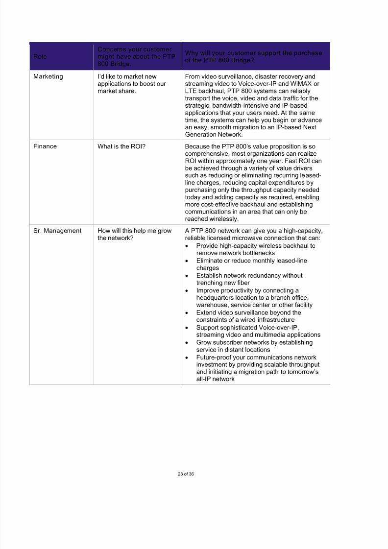
28 of 36
RoleConcerns your customer might have about the PTP800 Bridge.
Why will your customer support the purchaseof the PTP 800 Bridge?
Marketing I’d like to market newapplications to boost our market share.
From video surveillance, disaster recovery andstreaming video to Voice-over-IP and WiMAX or LTE backhaul, PTP 800 systems can reliably
transport the voice, video and data traffic for thestrategic, bandwidth-intensive and IP-basedapplications that your users need. At the sametime, the systems can help you begin or advancean easy, smooth migration to an IP-based NextGeneration Network.
Finance What is the ROI? Because the PTP 800’s value proposition is socomprehensive, most organizations can realizeROI within approximately one year. Fast ROI canbe achieved through a variety of value driverssuch as reducing or eliminating recurring leased-line charges, reducing capital expenditures by
purchasing only the throughput capacity neededtoday and adding capacity as required, enablingmore cost-effective backhaul and establishingcommunications in an area that can only bereached wirelessly.
Sr. Management How will this help me growthe network?
A PTP 800 network can give you a high-capacity,reliable licensed microwave connection that can:
• Provide high-capacity wireless backhaul toremove network bottlenecks
• Eliminate or reduce monthly leased-linecharges
• Establish network redundancy withouttrenching new fiber
• Improve productivity by connecting aheadquarters location to a branch office,warehouse, service center or other facility
• Extend video surveillance beyond theconstraints of a wired infrastructure
• Support sophisticated Voice-over-IP,streaming video and multimedia applications
• Grow subscriber networks by establishingservice in distant locations
• Future-proof your communications networkinvestment by providing scalable throughputand initiating a migration path to tomorrow’sall-IP network

7/27/2019 PTP 800 Sales Guid Release 03-00
http://slidepdf.com/reader/full/ptp-800-sales-guid-release-03-00 29/36
29 of 36
4.5 COMPETITION – THE PTP 800 VERSUS THE COMPETITION.
There are many competitors offering licensed microwave solutions today, and our PTP 800 is a relatively newentrant into this market. Competition worldwide includes Alcatel-Lucent, Ceragon, DragonWave, Ericsson,Exalt, Harris Stratex, Huawei, NEC, Nera, Nokia Siemens, Sagem, SM and Trangobroadband. Details aboutcompetitors’ information can be found at http://compass.mot.com/go/327595290
PTP 800 COMPETITIVE ADVANTAGES
• Higher Capacity: The PTP 800 enables faster communications for bandwidth-intensive applications suchas streaming video, Voice-over-IP and multimedia.
• More Scalabilit y: Because we offer a greater number of throughput capacity caps, you have moreflexibility to configure throughput for the immediate applications while providing growth for futurerequirements. At the same time, this extraordinary scalability can decrease the initial capital expenditure bynot having to pay for tomorrow’s needs with today’s budget.
• Errorless and Hitless ACM: You have the flexibility to operate in a Fixed Modulation mode or to utilize ACM. When ACM is enabled, the system will adjust modulation and/or coding rates to provide the highestthroughput and availability based on path conditions. As ACM steps from one modulation to another, PTP800 systems will experience no service interruption, while most comparable systems incur outages as the
radios change modulation. In addition, we embed ETSI/FCC regulation rules for ACM into the PTP 800’sinstallation wizard. So, there is never a worry about license violation. Most comparable systems do not givethe ACM mode details in their systems. As a result, the operator has to figure it out or hope that, if they arein violation of the license agreement, they don’t get caught.
• Asymmet ric Throughput Control : With asymmetric throughput control, you can assign differentthroughput capacities to the up and down links based on individual traffic patterns – a feature that is notavailable in many comparable systems.
• Superior Link Planning Capabili ties: The PTP LINKPlanner lets you plan and optimize links prior topurchase so there are no surprises when the system is deployed. Once a link is optimized to therequirements, LINKPlanner provides a detailed performance report that accurately predicts the link’sperformance and speeds deployment. In addition, LINKPlanner compiles a complete licensed-microwave
BOM to simplify ordering procedures. PTP LINKPlanner is the most comprehensive licensed-microwave linkplanning and optimization tool and a huge time-saver.
• End-to-End Network Management: You have great flexibility to manage links either locally or remotelyand to integrate PTP 800 management functions easily with existing Web or SNMP-based networkmanagement systems. In addition, our Wireless Manager software offers a common set of tools that greatlysimplify management functions and reduce management man-hours. Wireless Manager’s unified view of the wireless network allows operators to respond to problems faster and more easily.
7/27/2019 PTP 800 Sales Guid Release 03-00
http://slidepdf.com/reader/full/ptp-800-sales-guid-release-03-00 30/36
30 of 36
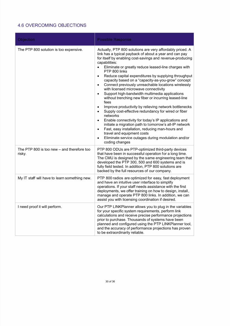
4.6 OVERCOMING OBJECTIONS
Objection Possible Response
The PTP 800 solution is too expensive. Actually, PTP 800 solutions are very affordably priced. Alink has a typical payback of about a year and can pay
for itself by enabling cost-savings and revenue-producingcapabilities:
• Eliminate or greatly reduce leased-line charges withPTP 800 links
• Reduce capital expenditures by supplying throughputcapacity based on a “capacity-as-you-grow” concept
• Connect previously unreachable locations wirelesslywith licensed microwave connectivity
• Support high-bandwidth multimedia applicationswithout trenching new fiber or incurring leased-linefees
• Improve productivity by relieving network bottlenecks
• Supply cost-effective redundancy for wired or fiber networks
• Enable connectivity for today’s IP applications andinitiate a migration path to tomorrow’s all-IP network
• Fast, easy installation, reducing man-hours andtravel and equipment costs
• Eliminate service outages during modulation and/or coding changes
The PTP 800 is too new – and therefore toorisky.
PTP 800 ODUs are PTP-optimized third-party devicesthat have been in successful operation for a long time.The CMU is designed by the same engineering team thatdeveloped the PTP 300, 500 and 600 systems and isfully field tested. In addition, PTP 800 solutions are
backed by the full resources of our company.
My IT staff will have to learn something new. PTP 800 radios are optimized for easy, fast deploymentand have an intuitive user interface to simplifyoperations. If your staff needs assistance with the firstdeployments, we offer training on how to design, install,manage and operate PTP 800 links. In addition, we canassist you with licensing coordination if desired.
I need proof it will perform. Our PTP LINKPlanner allows you to plug in the variablesfor your specific system requirements, perform linkcalculations and receive precise performance projectionsprior to purchase. Thousands of systems have beenplanned and configured using the PTP LINKPlanner tool,
and the accuracy of performance projections has provento be extraordinarily reliable.
7/27/2019 PTP 800 Sales Guid Release 03-00
http://slidepdf.com/reader/full/ptp-800-sales-guid-release-03-00 31/36
31 of 36
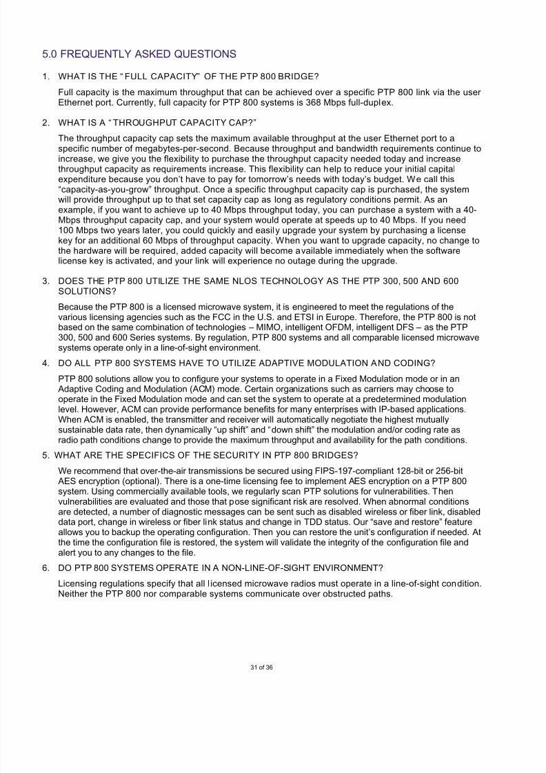
5.0 FREQUENTLY ASKED QUESTIONS
1. WHAT IS THE “ FULL CAPACITY” OF THE PTP 800 BRIDGE?
Full capacity is the maximum throughput that can be achieved over a specific PTP 800 link via the user Ethernet port. Currently, full capacity for PTP 800 systems is 368 Mbps full-duplex.
2. WHAT IS A “ THROUGHPUT CAPACITY CAP?”
The throughput capacity cap sets the maximum available throughput at the user Ethernet port to aspecific number of megabytes-per-second. Because throughput and bandwidth requirements continue toincrease, we give you the flexibility to purchase the throughput capacity needed today and increasethroughput capacity as requirements increase. This flexibility can help to reduce your initial capitalexpenditure because you don’t have to pay for tomorrow’s needs with today’s budget. We call this“capacity-as-you-grow” throughput. Once a specific throughput capacity cap is purchased, the systemwill provide throughput up to that set capacity cap as long as regulatory conditions permit. As anexample, if you want to achieve up to 40 Mbps throughput today, you can purchase a system with a 40-Mbps throughput capacity cap, and your system would operate at speeds up to 40 Mbps. If you need100 Mbps two years later, you could quickly and easily upgrade your system by purchasing a licensekey for an additional 60 Mbps of throughput capacity. When you want to upgrade capacity, no change tothe hardware will be required, added capacity will become available immediately when the softwarelicense key is activated, and your link will experience no outage during the upgrade.
3. DOES THE PTP 800 UTILIZE THE SAME NLOS TECHNOLOGY AS THE PTP 300, 500 AND 600SOLUTIONS?
Because the PTP 800 is a licensed microwave system, it is engineered to meet the regulations of thevarious licensing agencies such as the FCC in the U.S. and ETSI in Europe. Therefore, the PTP 800 is notbased on the same combination of technologies – MIMO, intelligent OFDM, intelligent DFS – as the PTP300, 500 and 600 Series systems. By regulation, PTP 800 systems and all comparable licensed microwavesystems operate only in a line-of-sight environment.
4. DO ALL PTP 800 SYSTEMS HAVE TO UTILIZE ADAPTIVE MODULATION AND CODING?
PTP 800 solutions allow you to configure your systems to operate in a Fixed Modulation mode or in an Adaptive Coding and Modulation (ACM) mode. Certain organizations such as carriers may choose tooperate in the Fixed Modulation mode and can set the system to operate at a predetermined modulation
level. However, ACM can provide performance benefits for many enterprises with IP-based applications.When ACM is enabled, the transmitter and receiver will automatically negotiate the highest mutuallysustainable data rate, then dynamically “up shift” and “down shift” the modulation and/or coding rate asradio path conditions change to provide the maximum throughput and availability for the path conditions.
5. WHAT ARE THE SPECIFICS OF THE SECURITY IN PTP 800 BRIDGES?
We recommend that over-the-air transmissions be secured using FIPS-197-compliant 128-bit or 256-bit AES encryption (optional). There is a one-time licensing fee to implement AES encryption on a PTP 800system. Using commercially available tools, we regularly scan PTP solutions for vulnerabilities. Thenvulnerabilities are evaluated and those that pose significant risk are resolved. When abnormal conditionsare detected, a number of diagnostic messages can be sent such as disabled wireless or fiber link, disableddata port, change in wireless or fiber link status and change in TDD status. Our “save and restore” featureallows you to backup the operating configuration. Then you can restore the unit’s configuration if needed. At
the time the configuration file is restored, the system will validate the integrity of the configuration file andalert you to any changes to the file.
6. DO PTP 800 SYSTEMS OPERATE IN A NON-LINE-OF-SIGHT ENVIRONMENT?
Licensing regulations specify that all l icensed microwave radios must operate in a line-of-sight condition.Neither the PTP 800 nor comparable systems communicate over obstructed paths.
7/27/2019 PTP 800 Sales Guid Release 03-00
http://slidepdf.com/reader/full/ptp-800-sales-guid-release-03-00 32/36
32 of 36
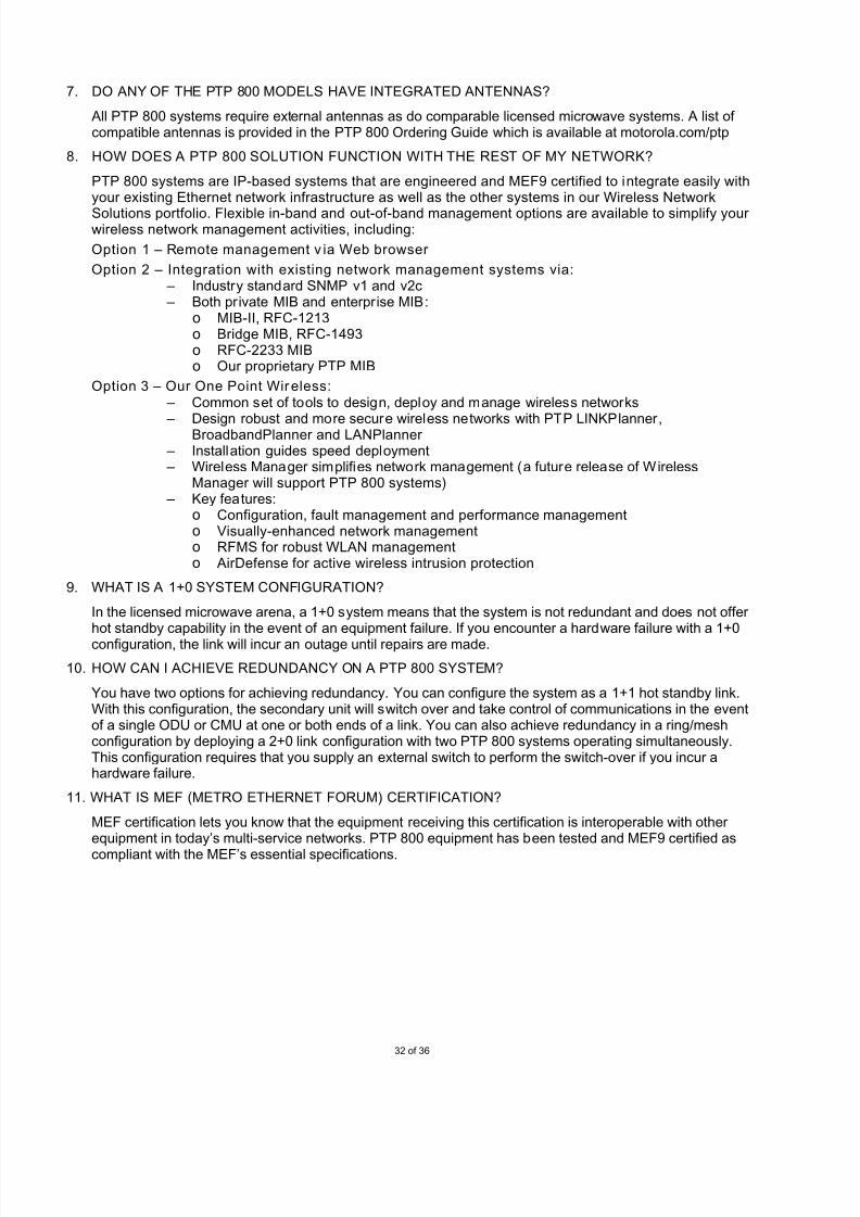
7. DO ANY OF THE PTP 800 MODELS HAVE INTEGRATED ANTENNAS?
All PTP 800 systems require external antennas as do comparable licensed microwave systems. A list of compatible antennas is provided in the PTP 800 Ordering Guide which is available at motorola.com/ptp
8. HOW DOES A PTP 800 SOLUTION FUNCTION WITH THE REST OF MY NETWORK?
PTP 800 systems are IP-based systems that are engineered and MEF9 certified to integrate easily withyour existing Ethernet network infrastructure as well as the other systems in our Wireless Network
Solutions portfolio. Flexible in-band and out-of-band management options are available to simplify your wireless network management activities, including:
Option 1 – Remote management v ia Web browser
Option 2 – Integration wit h existing network management systems via: – Industry standard SNMP v1 and v2c – Both private MIB and enterprise MIB:
o MIB-II, RFC-1213o Bridge MIB, RFC-1493o RFC-2233 MIBo Our proprietary PTP MIB
Option 3 – Our One Point Wireless: – Common set of tools to design, deploy and manage wireless networks – Design robust and more secure wireless networks with PTP LINKPlanner,
BroadbandPlanner and LANPlanner – Installation guides speed deployment – Wireless Manager simplifies network management (a future release of Wireless
Manager will support PTP 800 systems) – Key features:
o Configuration, fault management and performance managemento Visually-enhanced network managemento RFMS for robust WLAN managemento AirDefense for active wireless intrusion protection
9. WHAT IS A 1+0 SYSTEM CONFIGURATION?
In the licensed microwave arena, a 1+0 system means that the system is not redundant and does not offer hot standby capability in the event of an equipment failure. If you encounter a hardware failure with a 1+0
configuration, the link will incur an outage until repairs are made.
10. HOW CAN I ACHIEVE REDUNDANCY ON A PTP 800 SYSTEM?
You have two options for achieving redundancy. You can configure the system as a 1+1 hot standby link.With this configuration, the secondary unit will switch over and take control of communications in the eventof a single ODU or CMU at one or both ends of a link. You can also achieve redundancy in a ring/meshconfiguration by deploying a 2+0 link configuration with two PTP 800 systems operating simultaneously.This configuration requires that you supply an external switch to perform the switch-over if you incur ahardware failure.
11. WHAT IS MEF (METRO ETHERNET FORUM) CERTIFICATION?
MEF certification lets you know that the equipment receiving this certification is interoperable with other equipment in today’s multi-service networks. PTP 800 equipment has been tested and MEF9 certified as
compliant with the MEF’s essential specifications.
7/27/2019 PTP 800 Sales Guid Release 03-00
http://slidepdf.com/reader/full/ptp-800-sales-guid-release-03-00 33/36
33 of 36
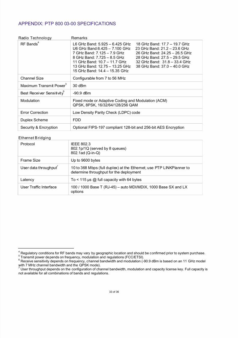
APPENDIX: PTP 800 03-00 SPECIFICATIONS
Radio Technology Remarks
RF Bands L6 GHz Band: 5.925 – 6.425 GHz 18 GHz Band: 17.7 – 19.7 GHzU6 GHz Band:6.425 – 7.100 GHz 23 GHz Band: 21.2 – 23.6 GHz7 GHz Band: 7.125 – 7.9 GHz 26 GHz Band: 24.25 – 26.5 GHz
8 GHz Band: 7.725 – 8.5 GHz 28 GHz Band: 27.5 – 29.5 GHz11 GHz Band: 10.7 – 11.7 GHz 32 GHz Band: 31.8 – 33.4 GHz13 GHz Band: 12.75 – 13.25 GHz 38 GHz Band: 37.0 – 40.0 GHz15 GHz Band: 14.4 – 15.35 GHz
Channel Size Configurable from 7 to 56 MHz
Maximum Transmit Power 30 dBm
Best Receiver Sensitivity -90.9 dBm
Modulation Fixed mode or Adaptive Coding and Modulation (ACM)QPSK, 8PSK, 16/32/64/128/256 QAM
Error Correction Low Density Parity Check (LDPC) code
Duplex Scheme FDD
Security & Encryption Optional FIPS-197 compliant 128-bit and 256-bit AES Encryption
Ethernet Bridging
Protocol IEEE 802.3802.1p/1Q (served by 8 queues)802.1ad (Q-in-Q)
Frame Size Up to 9600 bytes
User data throughput 10 to 368 Mbps (full duplex) at the Ethernet; use PTP LINKPlanner todetermine throughput for the deployment
Latency To < 115 µs @ full capacity with 64 bytes
User Traffic Interface 100 / 1000 Base T (RJ-45) – auto MDI/MDIX, 1000 Base SX and LXoptions
4Regulatory conditions for RF bands may vary by geographic location and should be confirmed prior to system purchase.
5Transmit power depends on frequency, modulation and regulations (FCC/ETSI).
6Receive sensitivity depends on frequency, channel bandwidth and modulation (-90.9 dBm is based on an 11 GHz model
with 7 MHz channel bandwidth and the QPSK mode).7
User throughput depends on the configuration of channel bandwidth, modulation and capacity license key. Full capacity isnot available for all combinations of bands and regulations.

7/27/2019 PTP 800 Sales Guid Release 03-00
http://slidepdf.com/reader/full/ptp-800-sales-guid-release-03-00 34/36
34 of 36
Management & Installation
Network Management In-band and out-of-band
Protocol SNMP v1/v2c
EMS Web GUI, our Wireless Manager or your existing network managementsystem
Out-of-Band Interface 10 / 100 Base T (RJ-45)
Installation ODU – RSSI output assistance for link alignment
Connection IF cable between outdoor unit (ODU) and compact modem unit (CMU),distance up to 1,000 ft. (300 meters) using the LMR600 cable; 630 ft. (190meters) is achievable with the CNT400 IF cable available from Motorola
Physical
Physical Configuration Split mount – Compact Modem Unit (CMU) and Outdoor Unit (ODU)
Dimensions ODU: Diameter 10.5” (26.7 cm), Depth 3.5” (8.9 cm)CMU: Width 7.1” (18.0 cm), Height 1.4” (3.5 cm), Depth 8.7” (22.0 cm)
Weight ODU: 10.1 lbs (4.6 kg)CMU: 2.4 lbs (1.1 kg)
Wind speed survival ODU: 150 mph (242 kph)
Power source -48V DC (-40.5V DC to -60V DC)
Power consumption 1+0 Configuration (1-ODU + 1-CMU)6 ~ 11 GHz: 71 Watts maximum13 ~ 38 GHz: 62 Watts maximum
1+1 Configuration (2-ODUs + 2-CMUs)6 ~ 11 GHz: 125 Watts maximum13 ~ 38 GHz: 110 Watts maximum
Environmental & Regulatory
Operating temperature ODU: -27° to +131° F (-33° to +55° C) – EN 300 019-1-4CMU: -27° to +131° F (-33° to +55° C) – EN 300 019-1-3
Humidity ODU: Up to 100%CMU: Up to 95%, non-condensing
Safety UL60950; IEC 60950; EN60950; CSA-C22.2 No. 60950
EMC USA: FCC Part 15, Class BEurope: EN 301 489-1 and EN 301 489-4
Radio Standard ETSI Harmonized Standard EN 302 217-2-2FCC Regulation Title 47, Part 101
Industry Canada Specification RSS-GEN and relevant SRSP Specifications
7/27/2019 PTP 800 Sales Guid Release 03-00
http://slidepdf.com/reader/full/ptp-800-sales-guid-release-03-00 35/36
35 of 36
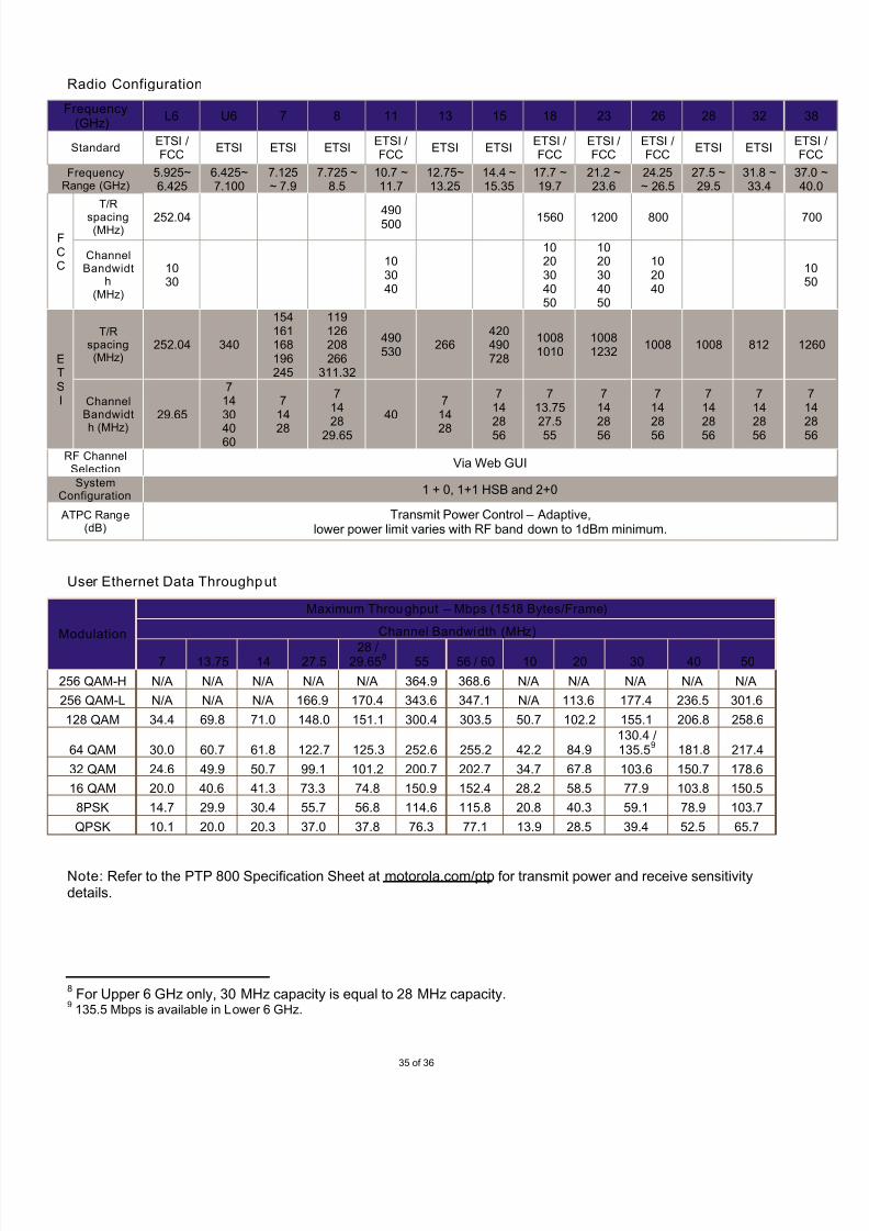
Radio Configuration
Frequency(GHz)
L6 U6 7 8 11 13 15 18 23 26 28 32 38
StandardETSI /FCC
ETSI ETSI ETSIETSI /FCC
ETSI ETSIETSI /FCC
ETSI /FCC
ETSI /FCC
ETSI ETSIETSFC
FrequencyRange (GHz)
5.925~6.425
6.425~7.100
7.125~ 7.9
7.725 ~8.5
10.7 ~11.7
12.75~13.25
14.4 ~15.35
17.7 ~19.7
21.2 ~23.6
24.25~ 26.5
27.5 ~29.5
31.8 ~33.4
37.040
FCC
T/R
spacing(MHz)
252.04 490500 1560 1200 800 70
ChannelBandwidt
h(MHz)
1030
103040
1020304050
1020304050
102040
1050
ETSI
T/Rspacing(MHz)
252.04 340
154161168196245
119126208266
311.32
490530
266420490728
10081010
10081232
1008 1008 812 126
ChannelBandwidt
h (MHz)
29.65
71430
4060
714
28
71428
29.65
40714
28
71428
56
713.7527.5
55
71428
56
71428
56
71428
56
71428
56
71428
56
RF ChannelSelection
Via Web GUI
SystemConfiguration
1 + 0, 1+1 HSB and 2+0
ATPC Range(dB)
Transmit Power Control – Adaptive,lower power limit varies with RF band down to 1dBm minimum.
User Ethernet Data Throughput
Modulation
Maximum Throughput – Mbps (1518 Bytes/Frame)
Channel Bandwid th (MHz)
7 13.75 14 27.528 /
29.658
55 56 / 60 10 20 30 40 50
256 QAM-H N/A N/A N/A N/A N/A 364.9 368.6 N/A N/A N/A N/A N/A
256 QAM-L N/A N/A N/A 166.9 170.4 343.6 347.1 N/A 113.6 177.4 236.5 301.6
128 QAM 34.4 69.8 71.0 148.0 151.1 300.4 303.5 50.7 102.2 155.1 206.8 258.6
64 QAM 30.0 60.7 61.8 122.7 125.3 252.6 255.2 42.2 84.9130.4 / 135.5
9181.8 217.4
32 QAM 24.6 49.9 50.7 99.1 101.2 200.7 202.7 34.7 67.8 103.6 150.7 178.6
16 QAM 20.0 40.6 41.3 73.3 74.8 150.9 152.4 28.2 58.5 77.9 103.8 150.5
8PSK 14.7 29.9 30.4 55.7 56.8 114.6 115.8 20.8 40.3 59.1 78.9 103.7
QPSK 10.1 20.0 20.3 37.0 37.8 76.3 77.1 13.9 28.5 39.4 52.5 65.7
Note: Refer to the PTP 800 Specification Sheet at motorola.com/ptp for transmit power and receive sensitivitydetails.
8For Upper 6 GHz only, 30 MHz capacity is equal to 28 MHz capacity.
9135.5 Mbps is available in Lower 6 GHz.

7/27/2019 PTP 800 Sales Guid Release 03-00
http://slidepdf.com/reader/full/ptp-800-sales-guid-release-03-00 36/36
MOTOROLA, MOTO, MOTOROLA SOLUTIONS and the Stylized M Logo are trademarks or registered trademarks of Motorola Trademark Holdings, LLC and are used under license. All other trademarks are the property of their respectiveowners. © 2011 Motorola Solutions, Inc. All rights reserved.
G4-23-106 WNS PTP 800 03-00 Sales Gd 012511
NOTE: The information presented herein is, to the best of our knowledge, true and accurate. No warrantyor guarantee expressed or implied is made regarding the capacity, performance or suitability of anyproduct. Information is subject to change without notice.