ptolemy: a framework for simulating...
TRANSCRIPT

August 31, 1992
1 of 34
A
•T
HE
•UN
IVE
RS I T Y • O F • C
AL
I FO
RN
IA•
•1868•
LET TH
E R E BE
LI G HT
Department of Electrical Engineeringand Computer Science
University of California
Berkeley, California 94720
Ptolemy: A Framework for Simulating andPrototyping Heterogeneous Systems
Joseph BuckSoonhoi Ha
Edward A. LeeDavid G. Messerschmitt
1.0 ABSTRACT
Ptolemy is an environment for simulation and prototyping of heterogeneous systems. It uses mod-ern object-oriented software technology (C++) to model each subsystem in a natural and efficientmanner, and to integrate these subsystems into a whole. Ptolemy encompasses practically allaspects of designing signal processing and communications systems, ranging from algorithms andcommunication strategies, simulation, hardware and software design, parallel computing, andgenerating real-time prototypes. To accommodate this breadth, Ptolemy must support a plethoraof widely-differing design styles. The core of Ptolemy is a set of object-oriented class definitionsthat makes few assumptions about the system to be modeled; rather, standard interfaces are pro-vided for generic objects and more specialized, application-specific objects are derived fromthese. A basic abstraction in Ptolemy is the Domain, which realizes a computational model appro-priate for a particular type of subsystem. Current examples of domains include synchronous anddynamic dataflow, discrete-event, and others appropriate for control software and embeddedmicrocontrollers. Domains can be mixed as appropriate to realize an overall system simulation.Some current applications of Ptolemy include networking and transport, call-processing and sig-naling software, embedded microcontrollers, signal processing (including implementation in real-time real-time), scheduling of parallel digital signal processors, board-level hardware timing sim-ulation, and combinations of these.
Key words: Heterogeneity, mixed-mode, simulation, prototyping, object-oriented programming
Invited paper in the International Journal of Computer Simulationspecial issue on “Simulation Software Development”.

INTRODUCTION
2 of 34 Ptolemy: A Framework for Simulating and Prototyping Heterogeneous Systems
2.0 INTRODUCTION
Ptolemy is a simulation and rapid prototyping framework for heterogeneous systems. It is
ideal for applications in which heterogeneity is a key characteristic. such as:
• Design of multimedia networks;
• Real-time embedded software;
• Hardware/Software codesign;
• Control and call-processing in telecommunications networks;
• Rapid prototyping of new telecommunications services;
• Mixed-mode hardware simulation;
• Mapping applications onto heterogeneous multiprocessor systems; and
• Mixed signal processing and real-time control.
For example, in the design of multimedia networks, we are interested in studying the interaction
between transport, compression or compositing signal processing, and control software in voice
or video services over cell-relay networks. In telecommunication systems we are interested in
studying the interaction between call-processing software and hardware switch elements. To
develop new telecommunication services, we must jointly design control software, signal pro-
cessing, transport, and hardware elements.
In hardware design we are interested in modeling components with varying detail, such as
behavioral, logic, timing, and circuit. In system-level design, we may wish to jointly design the
communications infrastructure and the processing elements. We may also wish to synthesize (in
combination) microcode for specialized processors, C code for generic processors, routing tables
for field-programmable gate arrays, and custom VLSI. We may wish to automate mappings onto
parallel processors by mixing specialized schedulers, such as those that target systolic arrays [11],
or those that address only applications with predictable control flow [28].

INTRODUCTION
Ptolemy: A Framework for Simulating and Prototyping Heterogeneous Systems 3 of 34
Simulation and system specification environments that support heterogeneity have been
developed before. For example, mixed-mode circuit simulation is now the standard way to deal
with complex VLSI circuits. At a higher level, the STATEMATE system by i-Logix [11] com-
bines activity charts, which describe dataflow, with statecharts [10], which describe control. A
very different flavor of heterogeneous system is acoordination language, like Granular Lucid
[14], which combines standard procedural languages with an “indexical model” (a sort of multidi-
mensional declarative model). Another example of a coordination language is Linda [5]. All of
these heterogeneous systems, however, assume a small number of pre-defined sets of semantics
that prove central to the system design. We avoid pre-defining the semantics we can accommo-
date.
An alternative to heterogeneity is generality. For example, VHDL is a relatively large lan-
guage with considerable semantic richness, so that it can accommodate different styles of system
description [13]. Petri nets can model parallelism and timing relationships in a huge variety of
applications [26]. In addition, specialized models can be combined into more general models with
unified semantics. For example, dataflow and discrete-event semantics have been combined for
hardware design [33] and graphical programming [31]. However, such generality has a price.
Analysis of systems using such general descriptions is difficult, and efficient compilers are diffi-
cult to implement. In the case of VHDL, for example, all effective VLSI synthesis tools restrict
their domain to a subset of the language. Unfortunately, each tool chooses a different subset, nul-
lifying the benefits of a standardized language. Similarly, effective parallel schedulers restrict
their domain to special cases of Petri nets. Furthermore, the complexity and diversity in system-
level design is only going to increase. Although any Turing-equivalent model can, in principle,
handle any computational design, clearly there are benefits from specializing the specification lan-
guage. We believe we cannot anticipate all the languages and models of computation that will
prove effective. Our approach, therefore, is to embrace heterogeneity by allowing the user to mix
different subsystem modeling descriptions, without restricting those descriptions.
The key innovation in Ptolemy is anon-dogmatic kernel that does not presuppose a data-
flow or functional model, finite-state machines, statecharts, communicating sequential processes,
or Petri nets. Rather, Ptolemy can accommodate all of these. Most importantly, the objective is to

INTRODUCTION
4 of 34 Ptolemy: A Framework for Simulating and Prototyping Heterogeneous Systems
combine descriptions so that complex systems can be designedheterogeneously. Ptolemy can be
viewed as a coordination language, but since it is not a language in any conventional sense, we
prefer to describe it as acoordination framework.
Of course, our limited resources have made it impossible to explore combinations of all
the models of computation described above. Hence, we cannot yet claim to have fully proven our
concept. Furthermore, our experience indicates that combining highly dissimilar models of com-
putation is not trivial. Our hope is that by providing an open architecture with well-defined inter-
faces, a community of users with very different design approaches can test our ideas.
A typical large system is structured as shown in Figure 1. It consists of heterogenous sub-
systems (some implemented in hardware, some in software) together with a software control sub-
system and a communications infrastructure. Ptolemy models such systems well. Consider for
example a portion of a multimedia connection through a broadband packet network as shown in
Figure 2. In this heterogenous system, the video compression (signal processing), transport (net-
working) and control (software) subsystems are most conveniently modeled in much different
ways, and yet there is a desire to study the interaction of these subsystems. Another example that
requires similar heterogeneity is shown in Figure 3. A computing resource (perhaps a futuristic
workstation) consists of a familiar UNIX1 processor, a separate processor running a specialized
real-time operating system, a third processor for hard-real-time signal processing (running no
operating system), and programmable hardware for truly intensive tasks (such as protocol imple-
mentations and I/O interfaces to custom devices). A unified environment for programming such a
1. UNIX is a trademark of AT&T.
Control
Subsystems
Communications
Figure 1. Typical structure of a large system.
ExternalEvents
ExternalEvents

INTRODUCTION
Ptolemy: A Framework for Simulating and Prototyping Heterogeneous Systems 5 of 34
heterogeneous combination of computing resources must support the different design styles that
would be used for each resource.
Ptolemy uses object-oriented software principles to achieve the following goals:
• Agility: Support distinct computational models, so that each subsystem can be simulated and
prototyped in a manner that is appropriate and natural to that subsystem.
• Heterogeneity: Allow distinct computational models to coexist seamlessly for the purpose of
studying interactions among subsystems.
Figure 2. A packet video connection through an ATM broadband packetnetwork.
CellAssembly
CellTransport
CellDisassembly
Control (setup, routing, flow control)
CompressionVideo
Source
Decompression
DummyTraffic
Display
UNIX1processor
real-timeprocessor
signalprocessor
programmablegate array
interconnect
user-interaction
software
real-time OS
and processes
hard-real-timesignal processing
customized I/O
interfaces
Figure 3. A heterogeneous hardware and software platform.
software
INTRODUCTION
6 of 34 Ptolemy: A Framework for Simulating and Prototyping Heterogeneous Systems
• Extensibility: Support seamless integration of new computational models and allow them to
interoperate with existing models with no changes to Ptolemy or to existing models.
• Friendliness: Use a modern graphical interface with a hierarchical block-diagram style of rep-
resentation.
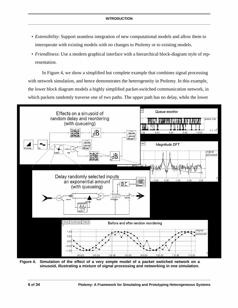
In Figure 4, we show a simplified but complete example that combines signal processing
with network simulation, and hence demonstrates the heterogeneity in Ptolemy. In this example,
the lower block diagram models a highly simplified packet-switched communication network, in
which packets randomly traverse one of two paths. The upper path has no delay, while the lower
Figure 4. Simulation of the effect of a very simple model of a packet switched network on asinusoid, illustrating a mixture of signal processing and networking in one simulation.

Internal Structure of Ptolemy
Ptolemy: A Framework for Simulating and Prototyping Heterogeneous Systems 7 of 34
path has random delay. At the receiving end, a queue stores incoming packets until they are
needed by the destination. In the upper left window is a highly simplified signal processing sys-
tem making use of the network. A sinusoid is generated and packetized, one sample per packet,
and launched into the network. At the receiving end, packets are used to reconstruct the sinusoid
at the same sample rate. The packets are used in the order of arrival, so the samples of the sinusoid
get randomly scrambled, as shown in the lower plot. Real-time constraints are modeled, so if
packets do not arrive in time, earlier packets are re-used. The effect on the spectrum is shown in
the middle plot, and the size of the queue is monitored in the upper plot.
In practical applications with similar structure, both the network model and the signal pro-
cessing will be much more elaborate. For instance, Ptolemy is currently being used to evaluate
video encoding algorithms for transmission over ATM (asynchronous transfer mode) networks.
3.0 Internal Structure of Ptolemy
Ptolemy relies heavily on the methodology of object-oriented programming (OOP). In this
section we describe the essentials of the class hierarchy that defines the Ptolemy kernel.
3.1 Blocks and Particles
The basic unit of modularity in Ptolemy is the Block1, illustrated in Figure 5. A Block
contains a module of code (the “go()” method) that is invoked at run-time, typically examining
data present at its input Portholes and generating data on its output Portholes. Depending on the
model of computation, however, the functionality of the go() method can be very different; it may
spawn processes, for example, or synthesize assembly code for a target processor. Its invocation is
directed by a Scheduler (another modular object). A Scheduler determines the operational seman-
tics of a network of Blocks. Blocks and Schedulers can be designed by end users, lending general-
ity while encouraging modularity. The hope is that Blocks will be well documented and stored in
standard libraries, rendering them modular, reusable software components.
1. When we capitalize a modular element, then it represents an object type. In object-oriented programming, objects encapsulateboth data, the state of the object, and functions operating on that state, called methods.

Internal Structure of Ptolemy
8 of 34 Ptolemy: A Framework for Simulating and Prototyping Heterogeneous Systems
PortHoles provide the standard interface through which Blocks communicate. Some of the
key PortHole methods are shown in Figure 5, such as “grabData()” and “sendData(),” which can
be invoked within the “go” method. A Scheduler interacts with Blocks through a standard set of
polymorphic1 methods such as “start()” to initialize the state of the Block, “go()” for runtime exe-
cution, and “wrapup()” to conclude the execution. Ptolemy also defines methods for building and
editing a network of Blocks, such as the “clone()” for creating another instance of the Block.
The user-interface view of the system is an interconnected block diagram. Blocks can
communicate using streams of Particles. A Particle is a base type for all messages. Simple exam-
ples of classes derived from Particle are FloatSample, FixSample, and ComplexSample, all used
in stream-oriented domains such as dataflow and discrete-event. A user can derive other message
types from the Particle, such as one-dimensional and two-dimensional data structures, data pack-
ets, and control tokens, invisibly to Ptolemy. This use of OOP inheritance2 allows Ptolemy to deal
transparently with many system modeling problems, such as speech, video, and packet data net-
1. Polymorphic methods is a term from object-oriented programming that refers to methods applied uniformly across a group ofsimilar objects. Each object substitutes the correct functionality for that object. Polymorphism is a powerful abstraction tool usedextensively in Ptolemy.
2. In object-oriented programming, inheritance refers to the derivation of a new, more functional and specialized, object type byincluding an existing inherited type and adding or replacing states and methods.
Figure 5. Block objects in Ptolemy send and receive data encapsulated inParticles to the outside world through Portholes. Buffering andtransport is handled by the Geodesic and garbage collection by thePlasma.
PortHole PortHole
Block• initialize()• start()• go()• wrapup()• clone()
PortHole• initialize()• grabData()• sendData()
PortHole PortHole
Geodesic
Plasma
Geodesic• initialize()• numInit()• setSourcePort()• setDestPort()
Particle• readType()• print()• operator << ()• clone()
Particle
Block Block

Internal Structure of Ptolemy
Ptolemy: A Framework for Simulating and Prototyping Heterogeneous Systems 9 of 34
works. The Geodesic class establishes the connection between PortHoles. The Plasma class man-
ages the reclamation of the used Particles so that elaborate garbage collection is not required.
Type conversions are performed automatically for the basic types provided with Ptolemy,
so that a block that produces integers can be connected with a block that expects real values, for
example. Type conversions may also be defined for user-defined Particles. Blocks can also be
defined to accept ANYTYPE; such blocks can route or duplicate Particles without regard to their
types. These Blocks manipulate Particles using only methods defined in the base class.
3.2 Stars, Galaxies, and the Universe
A conventional way to manage the complexity of a large system is to introduce a hierarchy
in the description, as shown in Figure 6. The lowest level (atomic) objects in Ptolemy are of type
Star, derived from Block. A Star that performs some computation belongs to adomain, as
explained below. The Stars in domain named “XXX” are of type XXXStar, derived from Star. A
Galaxy, also derived from Block, contains other Blocks internally. A Galaxy may contain inter-
nally both Galaxies and Stars. A Galaxy may exist only as a descriptive tool, in that a Scheduler
may ignore the hierarchy, viewing the entire network of blocks as flat. All our dataflow schedulers
do this to maximize the visible concurrency, getting the effect of non-strict function invocation.
Alternatively, a Scheduler may make use of the hierarchy to minimize scheduling complexity or
Figure 6. A complete Ptolemy application (a Universe) consists of a network ofBlocks. Blocks may be Stars (atomic) or Galaxies (composite). The“XXX” prefix symbolizes a particular domain (or model of computation).
Examples of Derived Classes• class Star:: Block• class XXXStar:: Star• class Galaxy:: Block• class Universe:: Galaxy, Runnable• class XXXUniverse:: Universe
XXXStar Galaxy XXXStar XXXStar
XXXStar
Galaxy XXXStar
XXXStar
XXXUniverse
Internal Structure of Ptolemy
10 of 34 Ptolemy: A Framework for Simulating and Prototyping Heterogeneous Systems
to structure synthesized code in a readable way. A Universe, which contains a complete Ptolemy
application, is a type of Galaxy. It is multiply derived from Galaxy and class Runnable. The latter
class contains methods for execution of simulation or synthesis of code.
3.3 Targets and Schedulers
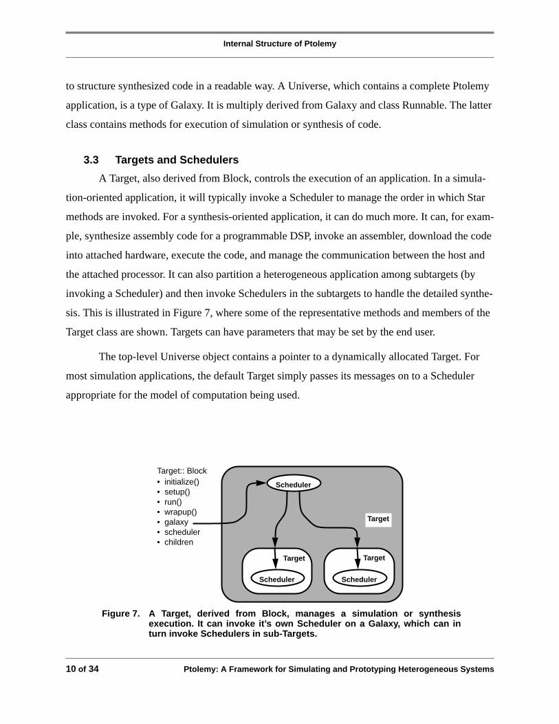
A Target, also derived from Block, controls the execution of an application. In a simula-
tion-oriented application, it will typically invoke a Scheduler to manage the order in which Star
methods are invoked. For a synthesis-oriented application, it can do much more. It can, for exam-
ple, synthesize assembly code for a programmable DSP, invoke an assembler, download the code
into attached hardware, execute the code, and manage the communication between the host and
the attached processor. It can also partition a heterogeneous application among subtargets (by
invoking a Scheduler) and then invoke Schedulers in the subtargets to handle the detailed synthe-
sis. This is illustrated in Figure 7, where some of the representative methods and members of the
Target class are shown. Targets can have parameters that may be set by the end user.
The top-level Universe object contains a pointer to a dynamically allocated Target. For
most simulation applications, the default Target simply passes its messages on to a Scheduler
appropriate for the model of computation being used.
Target:: Block• initialize()• setup()• run()• wrapup()• galaxy• scheduler• children
Scheduler
Target
Target Target
Scheduler Scheduler
Figure 7. A Target, derived from Block, manages a simulation or synthesisexecution. It can invoke it’s own Scheduler on a Galaxy, which can inturn invoke Schedulers in sub-Targets.

Internal Structure of Ptolemy
Ptolemy: A Framework for Simulating and Prototyping Heterogeneous Systems 11 of 34
3.4 Heterogeneity: The Domain
A Domain in Ptolemy consists of a set of Blocks, Targets, and associated Schedulers that
conform to a common computational model. By “computational model” we mean the operational
semantics governing how Blocks interact with one another. A Scheduler will exploit knowledge
of these semantics to order the execution of the Blocks. Two domains are illustrated in Figure 8.
Stars and Targets are shown within each domain. The inner Domain (designated YYY) in Figure
8 is an illustration of asub-Domain, which implements a more specialized model of computation
than the outer Domain (XXX). Hence all its Stars and Targets can also be used with the outer
Domain. Schedulers can be associated with more than one Domain, but a Scheduler for a sub-
Domain is not necessarily valid within the outer Domain. The Domain and the mechanism for co-
existence of Domains are the primary abstractions that distinguished Ptolemy from otherwise
comparable systems.
Some examples of Domains that are currently available or being designed are listed
below:
• Dynamic dataflow (DDF) is a data-driven model of computation originally proposed by Den-
nis [7]. Although frequently applied to design parallel architectures, it is also suitable as a pro-
gramming model [6], and is particularly well-suited to signal processing that includes
asynchronous operations. An equivalent model is embodied in the predecessor system Blosim
Figure 8. A Domain (XXX) consists of a set of Stars, Targets andSchedulers that support a particular model of computation. Asub-Domain (YYY) may support a more specialized model ofcomputation.
Scheduler
YYYDomain
Scheduler
Scheduler
YYYStarXXXStar
YYYStar
Target
Target
Target
XXXDomain
XXXStarYYYStar
Internal Structure of Ptolemy
12 of 34 Ptolemy: A Framework for Simulating and Prototyping Heterogeneous Systems
[23][24]. In DDF, Stars are enabled by data at their input PortHoles. That data may or may not
be consumed by the Star when it fires, and the Star may or may not produce data on its out-
puts. More than one Star may be fired at one time if the Target supports this parallelism. We
have used this domain to experiment with static scheduling of programs with run-time dynam-
ics [9]. The DDF Domain does not attempt to model the relative timing relationship of Block
invocations.
• Synchronous dataflow (SDF) [17][18] is a sub-Domain of DDF. SDF Stars consume and gen-
erate a static and known number of data tokens on each invocation. Since this is clearly a spe-
cial case of DDF, any Star or Target that works under the SDF model will also work under the
DDF model. However, an SDF Scheduler can take advantage of this static information to con-
struct a schedule that can be used repeatedly. Such a Scheduler will not always work with
DDF Stars. SDF is an appropriate model for multirate signal processing systems with ratio-
nally-related sampling rates throughout [3], and is the model used exclusively in Ptolemy’s
predecessor system Gabriel [19][2]. The advantages of SDF are ease of programming (since
the availability of data tokens is static and doesn’t need to be checked), a greater degree of
setup-time syntax checking (since sample-rate inconsistencies are easily detected by the sys-
tem), run-time efficiency (since the ordering of Block invocation is statically determined at
setup-time rather dynamically at run-time), and automatic parallel scheduling [29][30][20].
• Boolean dataflow (BDF) is a model intermediate between SDF and DDF, in which a limited
but practically important set of asynchronous operations (analogous to the if-then-else or case
statement in C) is supported, with many if not most of the advantages of SDF [4][21]. This is
an experimental domain currently being developed, and will be described in detail in a future
paper.
• Discrete event (DE) is a model in which only changes in system state (called events) are mod-
eled. This is an asynchronous model like DDF, but unlike DDF incorporates the concept of
global time in the system and orders Block invocations properly in time. A completely general
simulation system could be developed in the DE domain, at the expense of run-time efficiency
and ease and naturalness of programming for many applications like signal processing.

Internal Structure of Ptolemy
Ptolemy: A Framework for Simulating and Prototyping Heterogeneous Systems 13 of 34
• Message queue (MQ) is a model similar to DDF but with many more capabilities for dynami-
cally creating and destroying Blocks. The MQ domain is another experimental domain under
development targeted at software control applications, such as telephone switching call-pro-
cessing software. An interesting distinction between MQ and many other domains is that
graphical representations of the applications is probably neither reasonable nor appropriate.
In addition to these domains, it is possible to create domains out of previously-existing
simulation systems, as has been demonstrated with the Capsim [8] domain (incorporating the
Capsim signal processing system that is based on Blosim) and the Thor domain (incorporating the
Thor hardware timing simulator [32]). We are also beginning to design a domain with finite-state-
machine semantics.
The Domain class by itself makes Ptolemy agile (enabling modeling of different types of
systems in a natural and efficient manner), but we need to be able to mix those descriptions at the
system level). To accomplish this, Ptolemy allows different Domains to co-exist at different levels
of the hierarchy. Within a domain, it is permissible to have Blocks containing foreign domains.
At the user interface, a foreign Domain appears to be a property of an internal Galaxy.
However, at runtime it is a much different entity. A Galaxy does not have a Scheduler, and may be
destroyed by flattening prior to runtime, while a foreign Domain does have a Scheduler and must
not be flattened (its internal structure does not conform to the external model of computation). A
given simulation can therefore contain a number of Schedulers, which must be coordinated.
3.5 The Wormhole
The manner in which different domains coexist is a critical design element of Ptolemy,
and will therefore be further elaborated. As illustrated in Figure 9, the top-level view of a simula-
tion consists of a Universe. This Universe has an associated domain, say XXX, and is a Block of
type XXXUniverse (as shown in Figure 6). Internal to that Block is an XXXScheduler and a set of
XXXStars. (The description of the Universe may also include Galaxies, but we omit them
because they may be destroyed by flattening at runtime.) The introduction of a subsystem from a
foreign domain, say domain YYY, is illustrated in Figure 10. This is accomplished by adding a
Block which appears in the XXXDomain to be an XXXStar, but which is actually a much differ-

Internal Structure of Ptolemy
14 of 34 Ptolemy: A Framework for Simulating and Prototyping Heterogeneous Systems
ent object internally because it contains a YYYScheduler and a set of YYYStars. We call this spe-
cial object an XXXWormhole. One way to think of a Wormhole is as a Block which appears
externally to be a Star (it obeys the operational semantics of the external domain and appears to be
atomic to the external domain), but internally consists of an entire foreign Universe (Scheduler for
a foreign domain and Stars for that domain). A Wormhole can be introduced into the XXX
domain without any need for the XXXScheduler or other XXXStars to have knowledge of the
semantics of domain YYY.
It should be clarified that although most existing domains in Ptolemy have the internal
structure of Scheduler plus Stars, and are viewed at the user interface as an interconnected block
XXXStars
XXXUniverse
XXXScheduler
Figure 9. The Universe consists of a domain, and at runtime internal Starswhich conform to the operational semantics of that domain’sScheduler.
XXXScheduler
YYYScheduler
YYYStarsXXXStars
XXXWormhole
XXXUniverse
Figure 10. A new domain YYY is introduced by adding a Wormhole to theUniverse.

Internal Structure of Ptolemy
Ptolemy: A Framework for Simulating and Prototyping Heterogeneous Systems 15 of 34
diagram, this assumption is not built into Ptolemy. For purposes of interoperability, the only rele-
vant view of a domain is the external interface of a Wormhole, and as long as it conforms to this
external view it can have any internal structure whatsoever (just as a Star can have any internal
code). For example, one could have domains where every object talks to every other object, and
an interconnected block diagram makes no sense.
Wormhole objects also contain Target pointers; the Target by default may be the same as
that for the parent Universe, but can be different. This facility can be used to execute part of a
simulation on a workstation, while running another part of the simulation on a DSP board with
code generated and downloaded by Ptolemy. In this case, the Target object in the Wormhole
knows how to download and execute code on the DSP board.
3.6 The EventHorizon
The key to the support of heterogeneity in Ptolemy is the interoperability of different
domains at runtime. In turn, the key to this interoperability is the interface between the internal
structure of a Wormhole and its external environment. This interface is called the EventHorizon,
and is illustrated in Figure 11. A “universal” EventHorizon is shared by all domains, so that each
domain only needs to provide an interface to this EventHorizon. Hence we avoid having inter-
faces for Domains.
Figure 11. The universal EventHorizon provides an interface between theexternal and internal domains.
XXXUniverse
XXXWormhole
XXXDomain
YYYDomain
YYYtoUniversalXXXfromUniversal
YYYfromUniversalXXXtoUniversal
Eve
ntH
oriz
on
Scheduler
Scheduler
Particles
Particles
N2
N

Internal Structure of Ptolemy
16 of 34 Ptolemy: A Framework for Simulating and Prototyping Heterogeneous Systems
There are two types of interactions that occur at the EventHorizon as illustrated in Figure
11. The first is the conversion of Particles passing through the EventHorizon. For example, in
some domains each Particle has an associated timestamp, and in other domains it does not, and
hence there is the function of adding or deleting timestamps. The second interaction is the coordi-
nation of the Schedulers associated with the inside and outside domains. We will now describe
both interactions in more detail.
3.6.1 Particle Conversion at the EventHorizon
Conversion between domain-specific representations of a Particle is accomplished by
objects of class ToEventHorizon and FromEventHorizon, derived from EventHorizon, derived in
turn from Porthole. For each specific Domain XXX, we define XXXtoUniversal and XXXfromU-
niversal. Since these are ultimately derived from class XXXPorthole, the XXXWormhole looks
just like a XXXStar to XXX Domain. Particles are read from the XXXtoUniversal, transferred to
the YYYfromUniversal, and sent to the inside YYY domain.
Some Domains have a notion of simulated time, and some do not. In order for the event
horizon to work with both, when a Particle passes through the EventHorizon, it is always associ-
ated with a time stamp. A domain therefore need not know with which domain it is interacting.
See the next subsection for the detailed discussion of timing relationship between domains.
EventHorizons may have other domain-specific responsibilities. One example can be
found in SDFfromUniversal class. Suppose that the inner domain is SDF, the outer domain is DE,
and the DEWormhole has more than one input. The DEWormhole is executed when any input has
new data (an event). However, the inner SDF domain requires that all input data be available
before execution. To resolve this conflict, the DEWormhole checks all SDFfromUniversal Even-
tHorizons to see if they have enough data before turning control over to the inner SDFScheduler.
Thus, the SDFfromUniversal synchronizes the input data, enforcing the model of computation
assumed in the inside domain.
In some domains, Particle types are very restricted. For example, the Thor domain (used
for timing simulations of hardware) allows only bits. Particle type conversion, however, is not the
task of the EventHorizon. The Particle type of an EventHorizon is inherited from that of the Port-

Internal Structure of Ptolemy
Ptolemy: A Framework for Simulating and Prototyping Heterogeneous Systems 17 of 34
Hole connected to it. Particle type conversion between two different types of Particles is per-
formed automatically by the type conversion methods defined in the Particle class if both are
built-in types such as integer, float, and complex. Otherwise, the type conversion should be man-
aged explicitly by inserting special Stars (Packetize star, IntToBits Star, etc.).
3.6.2 Scheduler Coordination Across the EventHorizon
Viewed from the EventHorizon, every Wormhole contains a Target which in turn contains
a Scheduler, and every Scheduler has a set of polymorphic methods for the purposes of execution
of the domain and the coordination of Schedulers on both sides of an EventHorizon. Some of
these methods are illustrated in Figure 12. For purposes of executing a domain, the setup()
method does whatever is appropriate before execution of Blocks in the domain, for example the
static scheduling of Blocks in the SDF domain based on the interconnection topology and relative
sampling rates. The run() method then executes the Blocks by calling their run() methods in turn.
For purposes of coordinating two or more Schedulers, each Ptolemy Scheduler has an
additional concept of a StopTime. That is, run() is allowed to execute the Blocks in the domain
only up to the StopTime. One method of a Scheduler, setStopTime(), allows the StopTime to be
set externally.
Using these methods, multiple Schedulers can be made to behave logically as a single
Scheduler. Coordination of multiple DE Schedulers has been addressed in the area of distributed
simulation of discrete event systems, for example inconservative scheduling [25][28], but may
introduce artificial deadlocks because a notion of global time is not available to all processors. In
Ptolemy, Schedulers are hierarchically nested, making it easy to maintain a global time. Multiple
Schedulers behave logically as a single Scheduler and there is no artificial deadlock. To see how
this is achieved, assume for the moment that both the inside and outside Schedulers are (possibly
SchedulerScheduler: setup()
run()
setStopTime()
resetStopTime()
Figure 12. An illustration of some of the polymorphic messages of typeScheduler that support the coordination of two Schedulers.

Internal Structure of Ptolemy
18 of 34 Ptolemy: A Framework for Simulating and Prototyping Heterogeneous Systems
different) DE Schedulers. The basic structure of a DE Scheduler is shown in Figure 13. It incorpo-
rates the concept of a CurrentTime, and is parameterized by a StopTime, which is the maximum
allowed value of CurrentTime before execution is suspended. The EventQueue stores the un-pro-
cessed events, each corresponding to an action (typically arrival of a particular Particle at a partic-
ular PortHole of a particular Block) with a TimeStamp specifying the time of that action. The
EventQueue sorts the set of events by TimeStamp. In this and subsequent figures we assume that
the earliest event is on the left and the latest event is on the right.
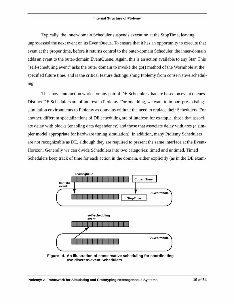
The coordination of Schedulers across the EventHorizon is illustrated in Figure 14. Sup-
pose the oldest (earliest) event in the EventQueue of the outer domain is an event at a Wormhole
EventHorizon. The outer-domain Scheduler calls the go() method of the WormHole (it treats it
like an ordinary star). The WormHole obtains the CurrentTime of the outer domain (which is
available to any Star) and sets the StopTime of its Scheduler to equal that time. It then invokes the
run() method of its Target, which in turn invokes the run() method of its Scheduler. By setting the
inner StopTime equal to the outer CurrentTime, the WormHole ensures that the inner domain can-
not get ahead of the outer domain in time. The CurrentTime of the outer domain can safely get
ahead of the CurrentTime of the inner domain, because the outer domain supplies all events to the
inner domain.
Figure 13. A discrete-event style of Scheduler keeps a sortedEventQueue and is parameterized by a StopTime.
DEScheduler
DEDomain
Tim
eSta
mp
Act
ion
earliestevent
EventQueue
StopTime CurrentTime
Internal Structure of Ptolemy
Ptolemy: A Framework for Simulating and Prototyping Heterogeneous Systems 19 of 34
Typically, the inner-domain Scheduler suspends execution at the StopTime, leaving
unprocessed the next event on its EventQueue. To ensure that it has an opportunity to execute that
event at the proper time, before it returns control to the outer-domain Scheduler, the inner-domain
adds an event to the outer-domain EventQueue. Again, this is an action available to any Star. This
“self-scheduling event” asks the outer domain to invoke the go() method of the Wormhole at the
specified future time, and is the critical feature distinguishing Ptolemy from conservative schedul-
ing.
The above interaction works for any pair of DE Schedulers that are based on event queues.
Distinct DE Schedulers are of interest in Ptolemy. For one thing, we want to import pre-existing
simulation environments to Ptolemy as domains without the need to replace their Schedulers. For
another, different specializations of DE scheduling are of interest; for example, those that associ-
ate delay with blocks (enabling data dependency) and those that associate delay with arcs (a sim-
pler model appropriate for hardware timing simulation). In addition, many Ptolemy Schedulers
are not recognizable as DE, although they are required to present the same interface at the Event-
Horizon. Generally we can divide Schedulers into two categories: timed and untimed. Timed
Schedulers keep track of time for each action in the domain, either explicitly (as in the DE exam-
Figure 14. An illustration of conservative scheduling for coordinatingtwo discrete-event Schedulers.
DEWormhole
earliestevent
EventQueue
StopTime
CurrentTime
DEWormhole
self-schedulingevent
Internal Structure of Ptolemy
20 of 34 Ptolemy: A Framework for Simulating and Prototyping Heterogeneous Systems
ple) or implicitly (as in the SDF Scheduler, where Particles do not have associated TimeStamps,
but nevertheless the Scheduler can associate a time with each new Particle implicitly because it
has the sampling rates or equivalent information). Untimed Schedulers do not keep track of time.
A Wormhole encapsulating an untimed domain must still model time from an external perspective
in case the external domain is timed. However, such a Wormhole is considered to be instanta-
neous; that is, it executes in zero time by associating the same TimeStamp with each outgoing
Particle as the TimeStamp of the most recent input. If this is too coarse a model for any particular
subsystem, then a timed-domain model can be substituted.
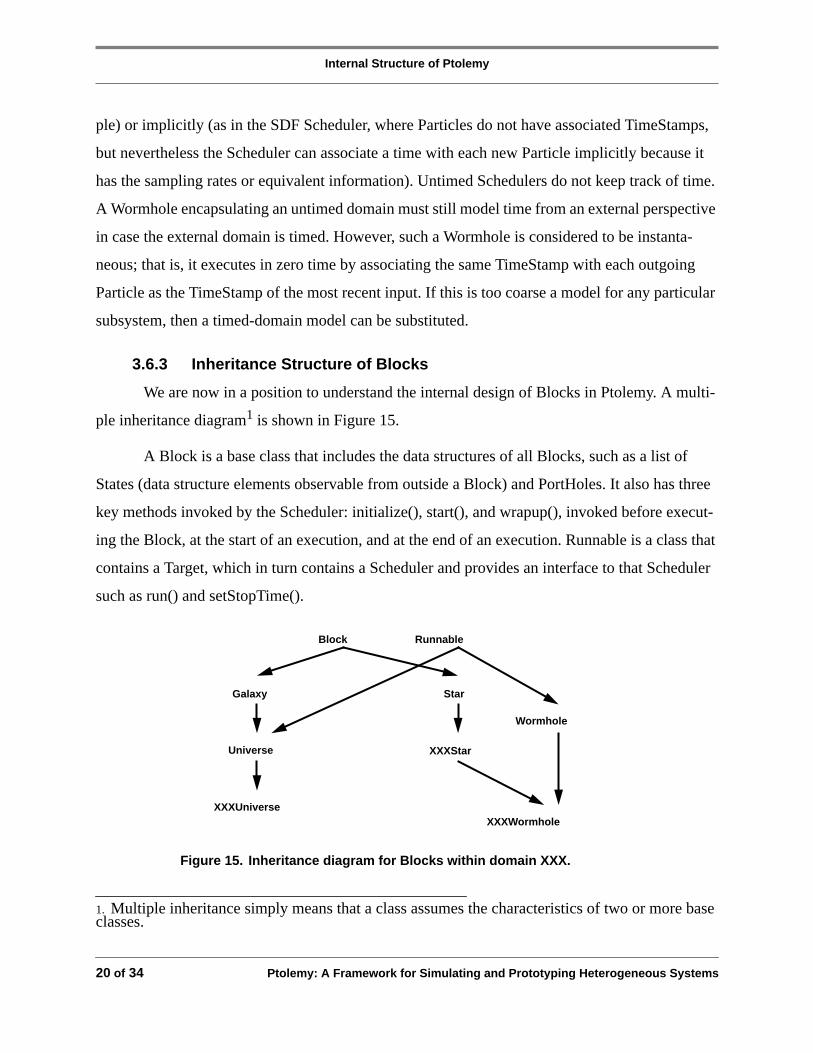
3.6.3 Inheritance Structure of Blocks
We are now in a position to understand the internal design of Blocks in Ptolemy. A multi-
ple inheritance diagram1 is shown in Figure 15.
A Block is a base class that includes the data structures of all Blocks, such as a list of
States (data structure elements observable from outside a Block) and PortHoles. It also has three
key methods invoked by the Scheduler: initialize(), start(), and wrapup(), invoked before execut-
ing the Block, at the start of an execution, and at the end of an execution. Runnable is a class that
contains a Target, which in turn contains a Scheduler and provides an interface to that Scheduler
such as run() and setStopTime().
1. Multiple inheritance simply means that a class assumes the characteristics of two or more baseclasses.
Block Runnable
Galaxy
Universe
Star
Wormhole
XXXStar
XXXWormholeXXXUniverse
Figure 15. Inheritance diagram for Blocks within domain XXX.
Internal Structure of Ptolemy
Ptolemy: A Framework for Simulating and Prototyping Heterogeneous Systems 21 of 34
From these base types, we define the particular types of Blocks. A Galaxy does not
include a Scheduler, but simply includes a list of internal Blocks with both internal and external
connections to those Block’s PortHoles. A Star is a Block that includes the additional method go()
(execute the internal code). A Universe is a Block that has all the characteristics of a Galaxy
(internally composed of interconnected Blocks) but also includes a Target and hence is a Runna-
ble. A Wormhole is simply a Runnable (has an internal Target) that includes an internal Galaxy as
well (in this sense it is very similar to a Universe)1.
For a specific domain XXX, there is an XXXUniverse which is a Universe with a compat-
ible Target that contains an XXXScheduler. An XXXStar is a Star that obeys the particular opera-
tional semantics of domain XXX; that is, it obeys specific rules on how it generates and consumes
Particles at its PortHoles. Finally, the domain has an XXXWormhole derived from XXXStar.
Thus the XXXWormhole provides all the methods of an XXXStar, but internally it is has a Galaxy
and a Scheduler, unlike XXXStars). Any type of Scheduler and Blocks can be inside the Worm-
hole. Neither the XXX domain nor the implementation of the XXXWormhole needs to know
about the inner domain.
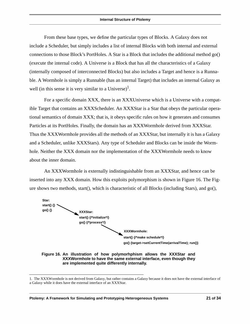
An XXXWormhole is externally indistinguishable from an XXXStar, and hence can be
inserted into any XXX domain. How this exploits polymorphism is shown in Figure 16. The Fig-
ure shows two methods, start(), which is characteristic of all Blocks (including Stars), and go(),
1. The XXXWormhole is not derived from Galaxy, but rather contains a Galaxy because it does not have the external interface ofa Galaxy while it does have the external interface of an XXXStar.
Star:
start() {}
go() {} XXXStar:
start() {/*initialize*/}
go() {/*process*/}
XXXWormhole:
start() {/*make schedule*/}
go() {target->setCurrentTime(arrivalTime); run()}
Figure 16. An illustration of how polymorhphism allows the XXXStar andXXXWormhole to have the same external interface, even though theyare implemented quite differently internally.

Internal Structure of Ptolemy
22 of 34 Ptolemy: A Framework for Simulating and Prototyping Heterogeneous Systems
which is characteristic of all Stars. The method start() is called each time a simulation is started or
restarted, and in the case of an XXXStar this method typically initializes the internal data struc-
tures of the XXXStar (as defined by the programmer of that XXXStar). In the case of an XXX-
Wormhole, this method does something quite different; namely, it calls a polymorphic Scheduler
method that initializes the schedule. Similarly, the method go() executes user-provided code in the
case of any XXXStar, but for an XXXWormhole calls the run() method provided by any Runna-
ble, which executes the schedule and in turn executes the Stars inside the Wormhole in the proper
order (through their respective go() methods).
In this manner, polymorphism allows us to achieve extensibility. Any new domain can be
added without any modifications to existing domains or to the kernel of Ptolemy itself, and that
new domain will be interoperable with the old domains.
3.7 Code Generation
The basic idea of code generation in Ptolemy is simple. The go() method of a code gener-
ation Star adds ASCII text to a data structure in the Target. The Scheduler, therefore, controls the
sequence of generated code. The Target collects the code and supervises the compilation and exe-
cution, if any. Any generic optimization capabilities can be put into the base class of the Target or
the code generation stars.
While a domain is specific to the computational model used, for code synthesis it is also
specific to the type of language generated. Hence, a C code generation domain following SDF
semantics is different from an assembly code generation domain following SDF semantics. This
is because the libraries of Stars and Targets for the two are quite distinct. The Target is specific to
the hardware that will run the code. A given language, particularly a generic language such as C,
may run on many targets; code generation functions are therefore cleanly divided between the
Domain and the Target.

Practical Details
Ptolemy: A Framework for Simulating and Prototyping Heterogeneous Systems 23 of 34
4.0 Practical Details
Ptolemy has been coded in C++, and successfully compiled using both commercial
(Cfront-based) and freely re-distributable (GNU) compilers. The development used Sun-3 and
Sun-4 (Sparc) platforms, and Ptolemy has been ported to the DECstation. Efforts are underway to
port it to an HP platform as well. The documentation for Ptolemy is extensive [1].
4.1 The Graphical User Interface
The Ptolemy interactive graphical interface (pigi) is a design editor based on tools from
the Berkeley CAD framework: the Oct database and the Vem graphical editor [12]. Using pigi,
Ptolemy applications are constructed graphically, by interconnecting icons. A special Ptolemy
class, InterpGalaxy (a derived type of Galaxy), is used to dynamically construct simulations based
on commands from the graphical interface. Incremental linking is supported, permitting addi-
tional stars to be defined, linked into the running pigi executable, and instantiated in the simula-
tion.
The graphical interface runs as two processes: one process is the Vem graphic editor; the
second, called pigiRpc, contains the Ptolemy kernel and the portion of the graphical interface that
knows about Ptolemy. The Unix RPC protocol is used for communication between the two pro-
cesses.
The graphical interface is by no means integral to Ptolemy. Indeed, we do not believe that
any single, homogeneous graphical interface will manage all Domains. Two separate textual inter-
faces, one with a Lisp-like syntax, and a second based on an embedded interpreter, Tcl [26], have
been developed. As with the graphical interface, the text-based interfaces also communicate with
the InterpGalaxy class to build and run simulations.
4.2 States
Ptolemy provides a State class, together with type-specific subclasses (IntState, FloatState,
StringState, IntArrayState, etc.) for use as parameters, observable variables, and as memory for

Some Representative Applications
24 of 34 Ptolemy: A Framework for Simulating and Prototyping Heterogeneous Systems
code generation applications. Because State objects are visible from the user interface, they can
be used to monitor and control the simulation, or to collect statistics.
Every State type has an initial-value string, which may be an expression that refers to
other states defined at higher levels (initializers for states in a star may refer to states in the parent
galaxy). Initial values of states are referred to as parameters by the user interface. The hierarchical
nature of states, and the fairly general expressions permitted, make it easy to define parameteriz-
able Galaxy objects.
4.3 Star Preprocessor Language
The Ptolemy preprocessor (a “schema compiler”) has been developed to make it easier to
write and document Star and Galaxy class definitions for use with Ptolemy. Instead of writing all
the initialization code required for a Ptolemy star (which contains quite a bit of “standard boiler-
plate”), the user can concentrate on writing the action code for a star and let the preprocessor gen-
erate the standard initialization code for PortHoles, States, etc. The preprocessor also generates
documentation in a standard format for inclusion in the manual.
5.0 Some Representative Applications
Several applications of Ptolemy that have been pursued will now be described. One pur-
pose of this will be to illustrate how the heterogenous aspect of Ptolemy manifests itself to the
user, and another purpose will be to illustrate how the use of OOP at the user-modeling level can
result in much more flexible models.
5.1 Broadband Networking
In the introduction, the use of Ptolemy for simulation of a broadband packet network with
associated signal processing is mentioned. Here we give a bit more detail. A block diagram of
such a simulation is shown in Figure 17. At the top (Universe) level, the cell-relay network con-
nects a set of terminals. The DE domain is used to model only non-empty cells travelling between
terminal and network, each cell marked with a TimeStamp. Internally the terminals have a com-

Some Representative Applications
Ptolemy: A Framework for Simulating and Prototyping Heterogeneous Systems 25 of 34
plicated structure (control, signal processing for video compression, etc.), but let us concentrate
on the network. Internally it consists of a signalling entity (programmed in the MQ domain) and a
set of interconnected ATM switches. The internal simulation of each ATM switch is in the SDF
domain (so that all cells are modelled, including empty cells) because the most convenient model
is as a synchronous digital machine (especially if we anticipate moving down to logic and timing
hardware-modeling levels). Within the switch there is another call-processing entity (in the MQ
domain) for control of this switch, and a shuffle-exchange type of interconnected 2x2 switches.
Finally, those switches consist of a 2x2 switching matrix plus associated routing tables.
Most interesting is the interconnection of foreign domains. Internal to Ptolemy this is han-
dled by the Wormhole, but it is also an issue at the level of user modeling. For example, cells that
arrive from the DE domain at a switch must be augmented with empty cells internal to the switch
Cell-
Relay
Network
TerminalsSignaling
ATM
Call-processing (MQ)Tables
2x2 Switch
(SDF)
(SDF)
(DE)(DE)
(MQ)
ATM
ATMATM
Figure 17. An ATM cell-relay simulation in Ptolemy, illustrating the hierarchicaldescription and mixture of domains. In each case the shaded blockis shown in internal detail.

Some Representative Applications
26 of 34 Ptolemy: A Framework for Simulating and Prototyping Heterogeneous Systems
to fill out an isochronous (constant rate) stream of cells, because the switch is modeled in the SDF
domain. This requires a cell interpolator driven by an isochronous clock at the interfaces to the
switch within the DE domain, so that cells passing the EventHorizon into the SDF domain have
uniformly spaced TimeStamps. Similarly, the communication between the call-processing in the
MQ domain within the switch and the routing tables within the switch in the SDF domain requires
an interpolator. In this case the MQ domain is untimed, and operates instantaneously from a timed
domain’s perspective. When a messages arrives from the network-level call processing, it passes
through the DE domain and therefore has appended TimeStamps. The switch-level call processing
then generates messages in response to update the routing tables, and these messages have the
same TimeStamp (since the MQ domain is untimed, the call-processing operates instantaneously).
Before these messages can be sent, however, they must be interpolated to an isochronous message
stream, because the routine tables are in the SDF domain.
This example illustrates that Ptolemy does not automatically solve all problems related to
interconnecting domains; rather, there is often work to be done at the user modeling level. Often,
however, this work is not an artifact of the modeling technique, but is a functional requirement in
the system being simulated. For example, the interpolation of messages from the call processing
arriving at the routing tables, a synchronous digital system, is a functional requirement of the sys-
tem being modeled.
5.2 Signal Processing
A wide variety of signal processing applications have been developed using Ptolemy,
including several adaptive filtering applications, power spectrum estimation, several parametric
and waveform coding techniques based on linear prediction, communication channel modeling,
digital communication receivers, beamforming, digital filter design, chaos simulations, phase-
locked loops, image coding, and music synthesis. Many of these applications are distributed with
the Ptolemy code as demonstrations.
Most signal processingalgorithms are conveniently defined within the synchronous data-
flow model of computation. Hence, for algorithm development and simulation, there is little need
for heterogeneity. However, turning an algorithm into a product involves both real-time prototyp-

Some Representative Applications
Ptolemy: A Framework for Simulating and Prototyping Heterogeneous Systems 27 of 34
ing and real-time control. For the former, we have been concentrating on synthesis of code for
parallel programmable DSP processors.
Ptolemy is capable of automatically partitioning, scheduling, and generating DSP assem-
bly language for a multi-processor DSP system [29][30]. Currently, it is required that the problem
fit the synchronous dataflow model; a future version will exploit heterogeneity to remove that
restriction by mixing Schedulers that operate at code-generation time with Schedulers that synthe-
size run-time code [9]. For real-time control, using the Wormhole concept, part of an application
can be run on a DSP board while the remainder of an application is executed on a host micropro-
cessor.
At present, Ptolemy can generate C code, Motorola 56000 and 96000 assembly code, and
assembly code for the Sproc multiprocessor DSP from Star Semiconductor. Code generation for
other processors is planned.
5.3 Hardware-Software Co-design
Most electronic systems mix custom circuit designs with programmable commodity parts.
Ptolemy supports such designs as a unit, since using the various domains described above, all
parts of the system can be modeled. For example, the Thor domain can be combined with a code
generation domain to design boards that mix custom hardware with programmable DSPs. Since
the hardware and software are both modeled within the same software framework, a designer can
easily explore tradeoffs between hardware and software implementations of various functions.
An example of such a design is shown in Figure 18 [15]. The top window shows the top
level of an algorithm that simulates the impairments of a telephone channel. This algorithm is
fairly complicated, including linear and non-linear distortion, frequency offset, phase jitter, and
additive Gaussian noise. The design is built in a code generation domain compatible with the SDF
model of computation. The bottom window shows a hardware design in the Thor domain contain-
ing two programmable DSPs communicating through a dual ported shared memory. This hard-
ware might be used to implement the telephone channel simulator for production-line testing of
voiceband data modems.

Some Representative Applications
28 of 34 Ptolemy: A Framework for Simulating and Prototyping Heterogeneous Systems
Algorithm Description
Target Hardware
Partition, Schedule and Generate DSP Assembly Code
Thor
DSP 56001 CODE GENERATOR
Figure 18. A hardware design (bottom) containing programmable DSPs can be developedtogether with the software (top) that will run on the DSPs. This Figure shows the toplevel only of a telephone channel simulation algorithm (top window) being mappedonto a board design with two Motorola DSP56001 DSPs.

Some Representative Applications
Ptolemy: A Framework for Simulating and Prototyping Heterogeneous Systems 29 of 34
The design shown in Figure 18 is one of many that could accomplish the stated objectives.
Using Ptolemy, the entire design, ranging from algorithm development to circuit design, can be
carried out within a unified environment. This enables exploration of many design alternatives
before resources are committed to hardware prototyping.
The hardware-software co-design problem is becoming increasingly important in large
(and even small) system design. One of the key advantages of Ptolemy is the ability to freely mix
behavioral, hardware, and software entities, modeling each in a natural way. In fact, in many
instances the actual production software can be developed in an appropriate Ptolemy domain, and
functionally tested in combination with its associated hardware subsystems.
5.4 Source and Link Modeling
A final example will illustrate the value of OOP abstractions in obtaining flexible models
in Ptolemy, using the simple example of the modeling of sources and links in the communications
network. Consider the simple situation modeled in Figure 19. We would like to be able to freely
intermix source and link models, regardless of the nature of the source or link. For example, the
source could generate data packets or speech samples or video frames, and the link could consist
of a simple bit-error model or a full physical-layer simulation. Using polymorphism in the Particle
can achieve this goal by defining in the Particle class methods convertToBits() and convertFrom-
Bits() which generate a bit-string representation of any Particle. The link model then accepts Par-
ticles, and employs convertToBits() to generate a bit string, apply the link model to that bit string,
and use Particle convertFromBits() to convert back to Particles at the output. There are a number
of issues in actually implementing this, but this oversimplification does illustrate the value of
OOP at the user-modeling level.
Source Link
Particles Particles
Figure 19. A simple network modeling problem.

CONCLUSIONS
30 of 34 Ptolemy: A Framework for Simulating and Prototyping Heterogeneous Systems
6.0 CONCLUSIONS
Ptolemy has been used internally in Berkeley for approximately two years for a growing
number of simulation efforts, such as signal processing, electric power network simulation, and
wireless and broadband network simulation. It has also been used successfully for instructional
purposes in one graduate and one undergraduate course. It has been distributed externally for
about one year, and is now used in a growing community of academic and industrial organiza-
tions. Aside from the usual problems of installation and environment compatibility, these efforts
can generally be characterized as very successful. The ability of Ptolemy to simulate, and to a
lesser extent rapidly prototype heterogeneous systems has been demonstrated by a number of
applications.
In terms of useful user models (Stars and Galaxies), the most fully-developed domain is
SDF, with many models for signal processing and data communications. Currently a similar set of
models is being developed in the DE domain for networking (packet, multiple access, and wire-
less) simulations. New domains are also under development. For example, a high-level circuit
synthesis domain based on synthesis work at Berkeley is planned.
There are also recognized deficiencies in the kernel of Ptolemy, and enhancements are
planned. One deficiency is the relatively simplistic manner in which a simulation is controlled
from the GUI at runtime. Another deficiency is the GUI itself, which unlike the remainder of
Ptolemy is not object-oriented. An OOP GUI design would encapsulate the interface to each
domain within that domain itself, allowing graphical interfaces to be customized for a domain.
Some of the extended capabilities of Ptolemy can be achieved in other ways, and it is use-
ful to compare them. For example, the generality of Ptolemy could be achieved by a single dis-
crete-event domain, which is itself completely general as a modelling tool. There are two
disadvantages:
• The discrete-event modeling of certain subsystems is unnatural, and will likely be resisted by
designers. Examples include multirate signal processing (where associating a time stamp with

ACKNOWLEDGEMENTS
Ptolemy: A Framework for Simulating and Prototyping Heterogeneous Systems 31 of 34
each sample is unnecessary and awkward) and control software domains (where not only is it
unnatural, but could not be considered for production software).
• Discrete-event modeling is significantly less efficient at runtime for some subsystems (the
aforementioned included). This needs, however, to be balanced by the additional overhead of
EventHorizon conversion in Ptolemy.
CAD frameworks allow design databases to be transferred from one tool to another.
Unlike Ptolemy they are focused on applying different toolkits (simulation, routing, logic minimi-
zation, etc.) to a common design. Such frameworks do not address the heterogeneous subsystem
problem directly (for example do not address control software). Further, frameworks typically
work through interprocess communication or file formats, whereas Ptolemy performs the simula-
tion in a common virtual address space (advantageous for efficiency in large simulations). With
respect to CAD frameworks, Ptolemy can be considered to be one tool.
The appropriate use of Ptolemy is as a basic framework for simulations (as well as proto-
typing tools). It can be used is a diversity of design groups focused on different aspects of a large
system design, where each group can tailor a domain or small set of domains to their need and lik-
ing. The major advantage is that the efforts of the different groups can readily be merged for the
purpose of checking interoperability. Also, different details of modeling can be used for each sub-
system (another form of heterogeneity): a high level (and rapidly executing) model for routine use
in simulation of other subsystems, down to a very detailed model of every subsystem (and very
slow execution) for final verification of the design. This is typically not done today.
With the increasing complexity of systems, the goal should be a design that is “right from
the start”. Ptolemy is a tool that can support that rigorous design style.
7.0 ACKNOWLEDGEMENTS
While this paper emphasizes the internal design of the Ptolemy kernel, a number of our
colleagues have contributed to Ptolemy and to the modeling in Ptolemy. The broader Ptolemy
project currently includes more than twenty students and three full-time-equivalent staff mem-

REFERENCES
32 of 34 Ptolemy: A Framework for Simulating and Prototyping Heterogeneous Systems
bers. Many of these people have made significant contributions to the ideas described in this
paper. Ichiro Kuroda contributed extensively to the early design of the State processor and inter-
preter. Edwin Goei is the principle architect of the GUI, with Wan-Teh Chang contributing some
refinements. The OCT/VEM group at Berkeley has been most cooperative in responding to our
requests for enhancements to that system.
The applications mentioned here have been pursued by other colleagues. Alan Lao, Wan-
Teh Chang, John Loh, and Philip Bitar have worked on networking models. Asawaree Kalavade
is working on hardware/software co-design and Tom Parks is working on embedded microcon-
trollers. Jose Pino is working on assembly code generation. A number of other colleagues are
working on other applications.
The Ptolemy project has been supported by the Defense Advanced Projects Research
Agency, the Semiconductor Research Corporation through its Berkeley Center of Excellence in
CAD/IC (Grant 92-DC-008), the National Science Foundation, the State of California MICRO
program, Bell Northern Research, Comdisco Systems, Dolby Labs, Hitachi, Hughes Network
Systems, Motorola, NEC, Philips, Rockwell, Sony, Star Semiconductor, and US West.
8.0 REFERENCES
[1] The Almagest: Manual for Ptolemy Version 0.3.1,Department of EECS, University of California, Berkeley, CA94720, USA, January, 1992.
[2] J. Bier, E. Goei, W. Ho, P. Lapsley, M. O’Reilly, G. Sih and E.A. Lee, “Gabriel: A Design Environment forDSP,” IEEE Micro Magazine, October 1990, Vol. 10, No. 5, pp. 28-45.
[3] J. Buck, S. Ha, E. A. Lee, and D. G. Messerschmitt, “Multirate Signal Processing in Ptolemy”,Proc. of the Int.Conf. on Acoustics, Speech, and Signal Processing, Toronto, Canada, April, 1991.
[4] J. Buck and E. A. Lee, “The Token Flow Model,” presented atData Flow Workshop, Hamilton Island, Australia,May, 1992.
[5] N. Carriero and D. Gelernter, “Linda in Context,”Comm. of the ACM,Vol. 32, No. 4, pp. 444-458, April 1989.
[6] A. L. Davis and R. M. Keller, “Data Flow Program Graphs,”IEEE Computer, Vol 15, No. 2, February 1982.
[7] J. B. Dennis, “Data Flow Supercomputers,”IEEE Computer, Vol 13, No. 11, November, 1980.
[8] L. James Faber, “Capsim”, ECE Dept. North Carolina State University, Raleigh, NC 27695
[9] Soonhoi Ha and E.A. Lee, “Compile-Time Scheduling and Assignment of Dataflow Program Graphs with Data-Dependent Iteration,”IEEE Transactions on Computers, November, 1991.

REFERENCES
Ptolemy: A Framework for Simulating and Prototyping Heterogeneous Systems 33 of 34
[10] D. Harel, “Statecharts: A Visual Formalism for Complex Systems,”Sci. Comput. Program.,vol 8, pp. 231-274,1987.
[11] D. Harel, H. Lachover, A. Naamad, A. Pnueli, M. Politi, R. Sherman, A. Shtull-Trauring, M. Trakhtenbrot,“STATEMATE: A Working Environment for the Development of Complex Reactive Systems,”IEEE Tr. onSoftware Engineering,Vol. 16, No. 4, April 1990.
[12] D. S. Harrison, P. Moore, R. Spickelmier, A. R. Newton, “Data Management and Graphics Editing in the Berke-ley Design Environment,”Proc. of the IEEE Int. Conf. on Computer-Aided Design,November 1986.
[13] IEEE Standard VHDL Language Reference Manual,IEEE STD 1076-1987, The IEEE, Inc., 345 East 47th St.,New York, NY, USA, 1987.
[14] R. Jagannathan and A.A. Faustini, “The GLU Programming Language,” Technical Report SRI-CSL-90-11,Computer Science Laboratory, SRI International, Menlo Park, California 94025, USA, November, 1990.
[15] A. Kalavade, “Hardware/Software Co-design Using Ptolemy”, MS Report, Electronics Research Laboratory,University of California, Berkeley, CA 94720, December, 1991.
[16] S. Y. Kung,VLSI Array Processors,Prentice-Hall, Englewood Cliffs, New Jersey, 1988.
[17] E. A. Lee and D. G. Messerschmitt, “Static Scheduling of Synchronous Data Flow Programs for Digital SignalProcessing”IEEE Transactions on Computers, January, 1987.
[18] E. A. Lee and D. G. Messerschmitt, “Synchronous Data Flow”IEEE Proceedings, September, 1987.
[19] E. A. Lee, W.-H. Ho, E. Goei, J. Bier, and S. Bhattacharyya, “Gabriel: A Design Environment for DSP”,IEEETrans. on ASSP, November, 1989.
[20] E. A. Lee and J. C. Bier, “Architectures for Statically Scheduled Dataflow”, reprinted inParallel Algorithmsand Architectures for DSP Applications,ed. M. A. Bayoumi, Kluwer Academic Pub., 1991.
[21] E. A. Lee, “Consistency in Dataflow Graphs”,IEEE Transactions on Parallel and Distributed Systems, Vol. 2,No. 2, April 1991.
[22] E. A. Lee, “A Design Lab for Statistical Signal Processing,”Proceedings of ICASSP,San Francisco, March,1992.
[23] D. G. Messerschmitt, “A Tool for Structured Functional Simulation,”IEEE J. on Selected Areas in Communica-tions,Vol. SAC-2, No. 1, January 1984.
[24] D. G. Messerschmitt, “Structured Interconnection of Signal Processing Programs,”Proc. of Globecom,Atlanta,Georgia, 1984.
[25] J.Misra, “Distributed Discrete-Event Simulation”,Computing Surveys, Vol. 18, No. 1, Nov. 1985.
[26] J. K. Ousterhout, “Tcl: An Embeddable Command Language”, 1990 Winter USENIX Proceedings, 1990.
[27] J. L. Peterson,Petri Net Theory and the Modeling of Systems,Prentice-Hall, Englewood Cliffs, New Jersey,1981.
[28] R. Righter, J. C. Walrand, “Distributed Simulation of Discrete Event Systems,”IEEE Proceedings, Vol. 77, No.1, pp. 99-113, January 1989.
[29] G.C. Sih, E.A. Lee, “A Compile-Time Scheduling Heuristic for Interconnection-Constrained HeterogeneousProcessor Architectures”, to appear, IEEE Trans. on Parallel and Distributed Systems,1992.
[30] G. C. Sih and E. A. Lee, “Declustering: A New Multiprocessor Scheduling Technique,” to appear inIEEETrans. on Parallel and Distributed Systems,1992.

REFERENCES
34 of 34 Ptolemy: A Framework for Simulating and Prototyping Heterogeneous Systems
[31] P. D. Stotts, “The PFG Language: Visual Programming for Concurrent Computing,”Proc. Int. Conf. on ParallelProgramming, Vol. 2, pp. 72-79, 1988.
[32] Thor Tutorial,VLSI/CAD Group, Stanford University, 1986.
[33] G. S. Whitcomb and A. R. Newton, “Data-Flow/Event Graphs,” Memorandum No. UCB/ERL M92/24, Elec-tronics Research Lab, University of California, Berkeley, CA 94720, USA, March 4, 1992.