pte-100-v - pan-amp · the pte-100-v equipment is a universal, portable, test system with an output...
TRANSCRIPT

Single phase relay test set Voltage / Current
PTE-100-V
PTE-100-V ingles 6/11/01 17:51 Página 2

PTE-100-V
MAIN FEATURES
– Variable voltage to 300 V or current to 8 A.– Variable frequency from 40 to 420 Hz.– Variable phase angle between 0 - 359.9°.– Output power: 100 VA.– Reversible output voltage/current.– Outputs are fully isolated and electronic.– Dynamic capability.– Completely programmable.– External current or voltage reference input.– External timer control output.– Dimensions: 200 x 300 x 200 mm / 13.5 Kg
8 x 12 x 8 in. / 30 lb
APPLICATIONS– Testing of single phase Generation and Interconnection
Relays, such as Frequency, Synchronizing, and PhaseAngle.
– Combining with a Current Injector, forms a completesingle phase test set (Current, Voltage, Phase Angle) totest single phase Directional, Power Relays, etc.
DESCRIPTIONThe PTE-100-V equipment is a universal, portable, testsystem with an output to test single phase protective relays.The output channel is reversible and can be either Voltageor Current.
The unit is extremely compact and rugged. The designincorporates the latest in modern digital microprocessortechnology to achieve unbeatable output characteristics interms of power, accuracy, low distortion, and dynamiccapability. This technology allows users to test manydifferent specific functions required in relay testing, withoutthe need of additional accessories.
All output signals are digitally generated, amplified, andinternally controlled by the IGM’s (Intelligent GeneratorModules), which interpret the orders received from the front
panel to produce a highly accurate, stable, and lowdistorted output, independent of the voltage supply.
The equipment also allows optional connection to acomputer for either automatic testing of relays or control ofthe equipment using Windows compatible software.
Even the adjustment and calibration of the equipment ismade by software, supplied with the units, which permitscalibration and/or adjustments in the outputs, without anyintervention in the hardware. (Closed Case Calibration)
In summary, the PTE-100-V is an equipment which offers allthe characteristics and functions needed for protectiverelay testing, in a manual or automatic mode, and inlaboratory and/or for on site testing.
Typical single phase system of 1 voltage (PTE-100-V) and 1 high current output (PTE-100-C).
PTE-100-V ingles 6/11/01 17:51 Página 3
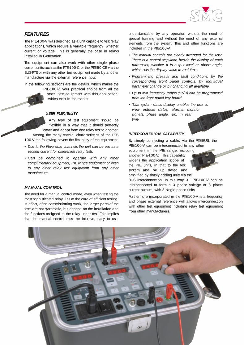
FEATURES The PTE-100-V was designed as a unit capable to test relayapplications, which require a variable frequency whethercurrent or voltage. This is generally the case in relaysinstalled in Generation.
The equipment can also work with other single phasecurrent units such as the PTE-100-C or the PTE-50-CE via theBUS-PTE or with any other test equipment made by anothermanufacture via the external reference input.
In the following sections are the details, which makes thePTE-100-V, your practical choice from all the
other test equipment with this application,which exist in the market.
USER FLEXIBILITY
Any type of test equipment should beflexible in a way that it should perfectly
cover and adapt from one relay test to another.Among the many special characteristics of the PTE-
100-V the following covers the flexibility of the equipment.
• Due to the Reversible channels the unit can be use as asecond current for differential relay tests.
• Can be combined to operate with any othercomplimentary equipment, PTE range equipment or evento any other relay test equipment from any othermanufacture.
MANUAL CONTROL
The need for a manual control mode, even when testing themost sophisticated relay, lies at the core of efficient testing.In effect, often commissioning work, the larger parts of thetests are not systematic, but depend on the installation andthe functions assigned to the relay under test. This impliesthat the manual control must be intuitive, easy to use,
understandable by any operator, without the need ofspecial training and without the need of any externalelements from the system. This and other functions areincluded in the PTE-100-V.
• The manual controls are clearly arranged for the user.There is a control step-knob beside the display of eachparameter, whether it is output level or phase angle,which sets the display value in real time.
• Programming pre-fault and fault conditions, by thecorresponding front panel controls, by individualparameter change or by changing all available.
• Up to two frequency ramps (Hz/s) can be programmedfrom the front panel key board.
• Total system status display enables the user toview outputs status, alarms, monitorsignals, phase angle, etc. in realtime.
INTERCONEXION CAPABILITY
By simply connecting a cable, via the PTE-BUS, the PTE-100-V can be interconnected to any otherequipment in the PTE range, includinganother PTE-100-V. This capabilitywidens the application scope ofthe PTE units, in that to the testsystem and be up dated andamplified by simply adding units via theBUS interconnection. In this way 3 PTE-100-V can beinterconnected to form a 3 phase voltage or 3 phasecurrent outputs with 3 single phase units.
Furthermore incorporated in the PTE-100-V is a frequencyand phase external reference will allows interconnectionwith other test equipment including relay test equipmentfrom other manufacturers.
PTE-100-V ingles 6/11/01 17:51 Página 4

PTE-100-VRS-232 COM PORTUsed to control the equipment from an external Computer, and can be usedto perform the following:• Connected to the Computer
- Software Calibration.- Automatic Testing.
• Connected to a printer to directly print test results.
1
PTE-BUSEnables the interconnection with any other unit in the PTE RANGE, allowing aneasy access for references, controls, etc.
2
POWER OUTPUTSThe unit has an output channel which may be used in Voltage or Currentmode up to 300 V in 3 ranges or up to 8 A in 2 ranges.All the outputs have a Dynamic Capability, which means that anycombination of Dynamic steps to 2nd values, can be selected in amplitudesand phase angles.
3
SELECTABLE REFERENCESThe power outputs can be synchronized to four different references in bothfrequency and phase. • The main supply phase (Line).• The BUS-PTE, when working with other PTE equipment (Bus).• External Phase Reference (Ext).• Internal Frequency Generator (Freq).
7
MAINS VOLTAGE SUPPLYThe voltage is supplied to the equipment by a standard SCHUKO male plugwith ground. Contain in this is a main filter to eliminate possible perturbationsfrom entering the equipment. Standard 5 x 20 mm. fuses protects the inputsand circuits.
8
EXTERNAL REFERENCE INPUTThe equipment can be synchronized, in terms of frequency and phase, withany external signal from 0.1 to 25A or in voltage from 5 to 300V.This feature enables the equipment to work with any other test set.
5
OUTPUTS PROTECTIONThe outputs and the unit are electronically protected against overload, short-circuit and over temperature. The appropriate alarm is indicated on the frontpanel, as well as the channel where it occurs. The outputs are fuse protected.
4
21
8
6
INTERNAL FREQUENCY GENERATORThe PTE-100-V enables frequency to be selected between 40 and 420Hz.Furthermore, by an easy to use preprogrammed key located on the frontpanel, frequency can be set to ramp (ROCOF) setting ramp-rates, stabilizedtimes and frequency levels. The slip frequency mode allows testing offrequency synchronisation where the frequency difference between anexternal reference is compared, with a resolution of 1mHz.Also included is a BNC output which gives a 5V TTL square wave output ofexactly the same frequency as is generated by the output.
6
PTE-100-V ingles 6/11/01 17:51 Página 5
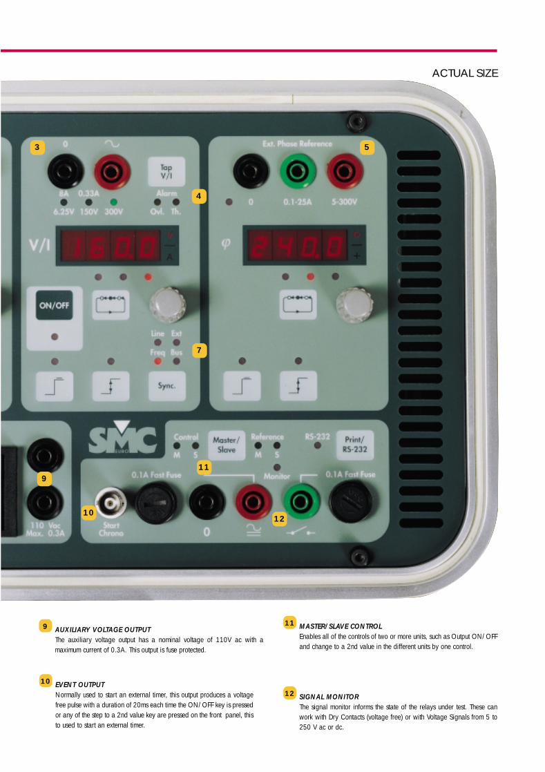
EVENT OUTPUTNormally used to start an external timer, this output produces a voltagefree pulse with a duration of 20ms each time the ON/OFF key is pressedor any of the step to a 2nd value key are pressed on the front panel, thisto used to start an external timer.
10
MASTER/SLAVE CONTROLEnables all of the controls of two or more units, such as Output ON/OFFand change to a 2nd value in the different units by one control.
11
SIGNAL MONITORThe signal monitor informs the state of the relays under test. These canwork with Dry Contacts (voltage free) or with Voltage Signals from 5 to250 V ac or dc.
12
AUXILIARY VOLTAGE OUTPUTThe auxiliary voltage output has a nominal voltage of 110V ac with amaximum current of 0.3A. This output is fuse protected.
9
119
1012
7
3
4
5
ACTUAL SIZE
PTE-100-V ingles 6/11/01 17:51 Página 6

COMPUTER CONTROL The PTE-100-V can be completely controlled by anexternal computer, along with its corresponding softwareprograms with various levels and objectives. The PTE-100-V uses the PTE-12 adapter, which connects tothe RS 232 serial port of the computer to the BUS-PTE porton the unit. The corresponding software of the PTE-100-V is divided invarious packages and optional programs which gives avariety of application use. These are:
EUROTEST ERTST-1VThis software enables automatic and systematic testsroutines, with standard routine tests for each type of relays.There is also a library of routine tests supplied with thesoftware. These can easily be edited to adapt to theapplication desired or the user can create new routines.
EUROFAULTEnables the playback of any previously registered orcalculated fault in COMTRADE format. The bandwidth is0.5 to 5000 Hz.
PTE-CALEnables the adjustment and calibration of the unit , withoutthe need of any intervention inside the equipment. (ClosedCase Calibration)
UNO SYSTEM. A complete programablesingle phase system with 1 voltage (PTE-100-V) and 1 current (PTE-50-CE).
PTE-100-V ingles 6/11/01 17:51 Página 7
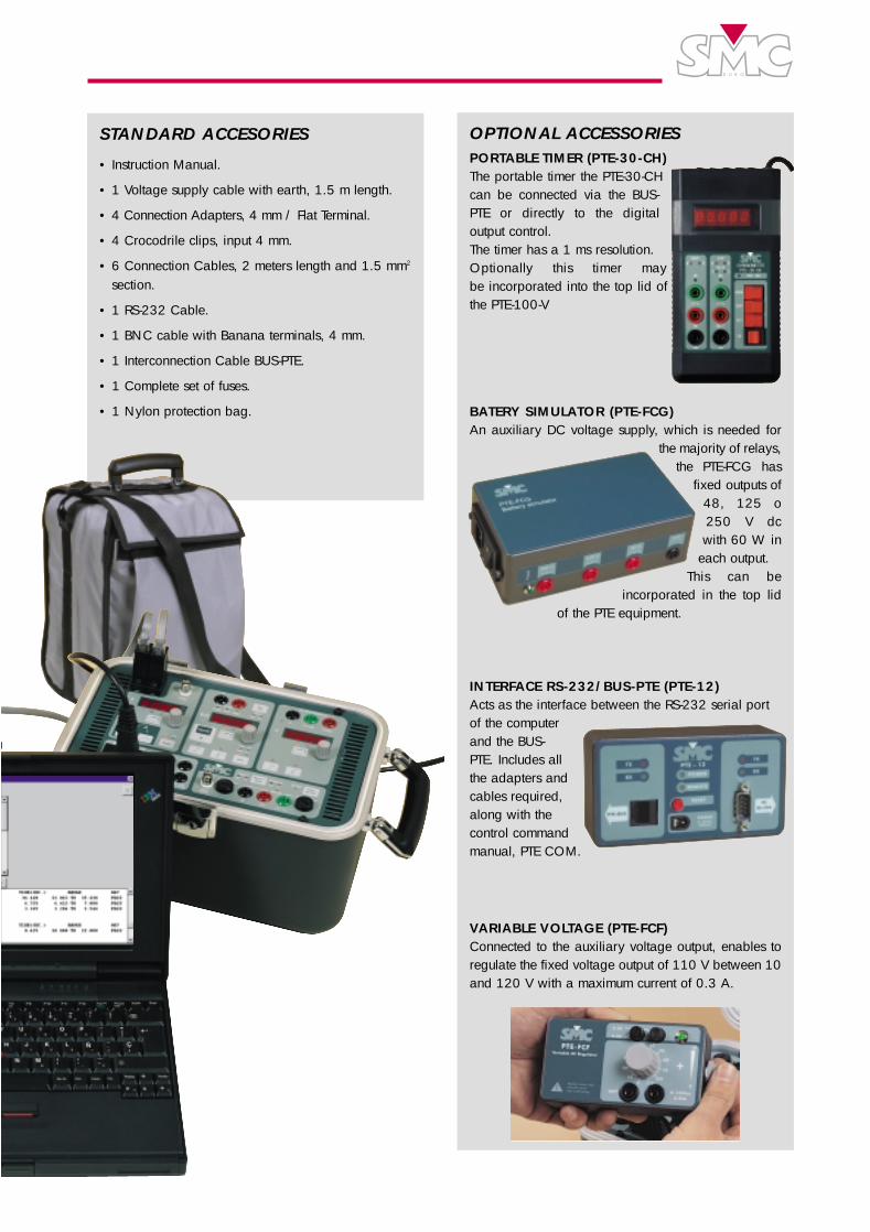
OPTIONAL ACCESSORIES PORTABLE TIMER (PTE-30-CH)The portable timer the PTE-30-CHcan be connected via the BUS-PTE or directly to the digitaloutput control. The timer has a 1 ms resolution.Optionally this timer may be incorporated into the top lid ofthe PTE-100-V
BATERY SIMULATOR (PTE-FCG)An auxiliary DC voltage supply, which is needed for
the majority of relays,the PTE-FCG has
fixed outputs of48, 125 o250 V dcwith 60 W in
each output. This can be
incorporated in the top lidof the PTE equipment.
INTERFACE RS-232/BUS-PTE (PTE-12)Acts as the interface between the RS-232 serial portof the computerand the BUS-PTE. Includes allthe adapters andcables required,along with thecontrol commandmanual, PTE COM.
VARIABLE VOLTAGE (PTE-FCF)Connected to the auxiliary voltage output, enables toregulate the fixed voltage output of 110 V between 10and 120 V with a maximum current of 0.3 A.
STANDARD ACCESORIES
• Instruction Manual.
• 1 Voltage supply cable with earth, 1.5 m length.
• 4 Connection Adapters, 4 mm / Flat Terminal.
• 4 Crocodrile clips, input 4 mm.
• 6 Connection Cables, 2 meters length and 1.5 mm2
section.
• 1 RS-232 Cable.
• 1 BNC cable with Banana terminals, 4 mm.
• 1 Interconnection Cable BUS-PTE.
• 1 Complete set of fuses.
• 1 Nylon protection bag.
PTE-100-V ingles 6/11/01 17:52 Página 8

EUROSMC, S.A.Polígono Industrial P-29, Calle Buríl, 69. 28400 Collado-Villalba. Madrid (Spain). Tels: 34 - 91 - 849 89 80*. Fax: 34 - 91 - 851 25 53
www.eurosmc.com • e-mail: [email protected]
POWER OUTPUT MODE RANGES Permanent Permanent Maximum Permanent Power
LEVEL RESOLUTION Current Voltage Accuracy Distortion Power 1 minute
0 - 6.25V 0.01 - 0.1 - 1V 8A -
VOLTAGE 0 - 150V 0.01 - 0.1 - 1V 0.33A - ±0.5% 1% 50VA 100VA
0 - 300V 0.01 - 0.1 - 1V 0.15A -
CURRENT0 - 0.330A 0.001 - 0.01 - 0.1A - 150V
± 0.5% 1% 50VA -0 - 8.000A 0.001 - 0.01 - 0.1A - 6.25V
PHASE ANGLE 0 - 359.9º 0.1 - 1 - 10º - - ± 0.5º - - -
TRANSIENT BANDWIDTH: 0.5 - 5000 Hz
EXTERNAL REFERENCE INPUTMODE SIGNAL RANGE FREQUENCY RANGE INPUT IMPEDANCE
VOLTAGE 5 - 300 V 40 - 70 Hz 47 KΩCURRENT 0.1 - 25 A 40 - 70 Hz 25 mΩ
GENERALAuxiliary Voltage Output: NomV: 115 Vac/MaxI: 0.3 Aac/Fuse protected
Temperature Range: Operation: 0 - 50° C /Storing: -20° - 70° CVoltage supply: 230 V ± 10% (Standard version) 50-60 Hz
115 V ± 10% (upon request) 60 Hz.Dimensions: Height:200 mm Width: 300 mm Depth: 200 mm
8” 12” 8”Weight: 13,5 Kg. - 12 lb.
TECHNICAL SPECIFICATION
Plea
se N
ote:
Due
to th
e co
ntin
uous
rese
arch
and
dev
elop
men
t by
EURO
SMC
, spe
cific
atio
ns in
this
cata
log
may
be
chan
ged
with
out p
revio
us n
otic
e.
DISTRIBUTED BY:
INTERNAL FREQUENCY GENERATORMODE RANGE RESOLUTION ACCURACY SLOPE RANGE DURATION RANGE
STANDARD 40 - 420 Hz 0.01 - 0.1 - 1 Hz. ±0.003 Hz. 0.1 - 10.0 Hz/s. 0.01 - 10.0 s.DIFFERENTIAL 0.001 - 10 Hz. 0.001 - 0.01 - 0.1 Hz. ±0.001 Hz. - -
SIGNAL MONITORDry Contact Input
• Open circuit voltage: 10.2 V. D.C.
• Short-circuit current: 25 mA
• Fuse protected.
Voltage input
• Level Limits: From 5 to 250 V A.C./D.C.
• Input Impedance: 19 KΩ• Fuse protected.
DIGITAL CONTROL OUTPUTMaximum AC Voltage: 20 V
Maximum DC Voltage: ± 28 V
Maximum AC/DC Current: 0.5 A
AC Power: 10 VA
DC Power: 14 W
PTE-100-V ingles 6/11/01 17:51 Página 1