psa/beta partnership for assembly · psa/beta partnership for assembly ... & associated...
TRANSCRIPT

7 BEFORE REALITY CONFERENCE
PSA/BETA PARTNERSHIP FOR ASSEMBLY 1*Franck Norreel, 2Irene Makropoulou 1Groupe PSA, France, 2BETA CAE Systems S.A., Greece KEYWORDS – Assembly, Automation, A-Points, Connectors ABSTRACT – Following PSA’s decision to choose ANSA as the pre-processing tool for Nastran, Radioss and Abaqus models, BETA & PSA collaborated to identify the best methodology to generate a complete assembly of models. This new PSA assembly process and ANSA v17 have been simultaneously developed with a common target: creation of a modern, effective and efficient process and all related infrastructure. The process handles three main modelling stages: 1. Body welding assembly
The PLM system launches ANSA in batch mode to produce automatic meshes of parts.
The PLM system stores meshed representations of parts together with their meta-data (attributes).
While exporting mesh files, a “Synoptic” file is simultaneously exported, allowing automatic Body creation.
Benefit: Spotwelds and linear connections are fixed before model creation thanks to these files.
Result is a fully automated welding assembly for Body, ready to run immediately at the beginning of model creation.
2. Bolt and other assemblies:
Bolts are decomposed in 2 “bolt” connections: 1 “screw” + 1 “nut”.
Each bolt realization is associated to one Assembly Point (A-Point).
A connector is automatically created between A-Points if they respect PSA-assembly criteria.
3. Application : Automated Vehicle assembly for all disciplines and configurations :
Assembly is “prepared” subsystem by subsystem, independently from complete model and from id management.
Inter-subsystem connectivity is based on the automatic creation of connectors. Next step: ANSA SimManager connector:
To compare Body model to PLM synoptic
To synchronize subsystem model versions between ANSA and SimManager

7 BEFORE REALITY CONFERENCE
TECHNICAL PAPER - 1. INTRODUCTION Context
CAD tool evolution / PLM deployment
CAD definition migrates to ENOVIA, linked to PLM solution of Dassault Systèmes. Pre-processing tool evolution
Pre-processing tool for Crash, NVH & Structure models migrates to ANSA.
As ANSA offers a very good scriptability (in python language), a lot of automation tools can be developed
“Lead time” reduction Since 2015, PSA put high priority on “lead time reduction”. “Lead time” definition for PSA is time between frozen CAD definition and first simulation result for each milestone of a vehicle project.
Target was to divide “Lead time” for Front crash by 2. New process FOR Front crash model creation
1. Target of new process is to mesh individual CADs automatically as soon as they are frozen. Before official complete content, assembly can be prepared on available auto-meshes and auto-meshes can be set to target quality
2. As a consequence, when all CADs are officialised, assembly can be hardly fully prepared.
3. Once assembly preparation is ready, finalized meshes can be automatically assembled.
4. Model setup generation has been improved, too: standardization per discipline + automation tools allow a huge reduction of time for model setup.
5. This automation allows engineers to continue to spend necessary time on result analysis.
Figure 1 – Front crash model generation process
Current paper introduces first part of this process dedicated to assembly (Points 1 to 3).
7 BEFORE REALITY CONFERENCE
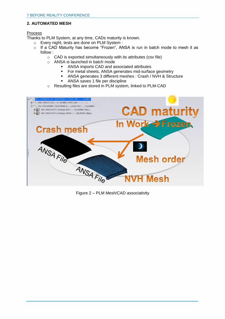
2. AUTOMATED MESH Process Thanks to PLM System, at any time, CADs maturity is known.
o Every night, tests are done on PLM System : o If a CAD Maturity has become “Frozen”, ANSA is run in batch mode to mesh it as
follow : o CAD is exported simultaneously with its attributes (csv file) o ANSA is launched in batch mode
ANSA imports CAD and associated attributes For metal sheets, ANSA generates mid-surface geometry ANSA generates 3 different meshes : Crash / NVH & Structure ANSA saves 1 file per discipline
o Resulting files are stored in PLM system, linked to PLM-CAD
Figure 2 – PLM Mesh/CAD associativity

7 BEFORE REALITY CONFERENCE
Mesh file content After meshing, ANSA file is saved with a standardized name referring name of PLM object. Ansa file contains 2 ANSA Parts:
1. Initial geometry: This part is marked as inactive => generally, it should not be useful, but it can be used to rebuild a midsurface or a geometry detail for example
2. Mesh part : a. Content : Meshed Midsurface (or meshed volume) & associated property
(Thickness + Material name) b. Attributes :
i. Useful attributes for model creation : 1. “Code_tole” is an identifier of welded flanges ; it is used to
define welded connections 2. Decoupage_PSA is a standard code designing the part type; it
is to design model organisation ii. Other Attributes (PLM attributes)
Figure 3 – ANSA Mesh Part content
Module ID: Official PSA Identifier of the CAD
Code_Tole: PSA Identifier for welding assembly
Decoupage_PSA: PSA standard Code for Part type (ex:
Left B-Pillar reinforcement part…)
7 BEFORE REALITY CONFERENCE
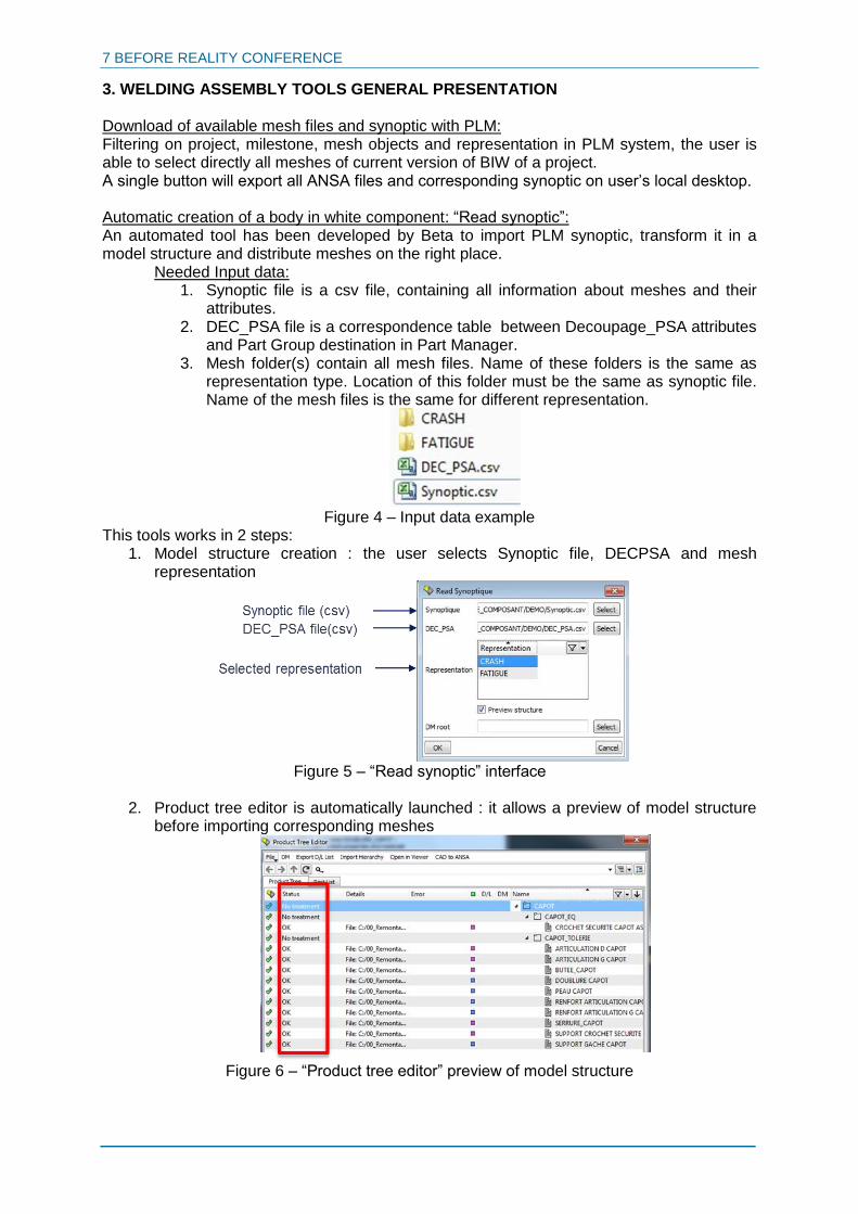
3. WELDING ASSEMBLY TOOLS GENERAL PRESENTATION Download of available mesh files and synoptic with PLM: Filtering on project, milestone, mesh objects and representation in PLM system, the user is able to select directly all meshes of current version of BIW of a project. A single button will export all ANSA files and corresponding synoptic on user’s local desktop. Automatic creation of a body in white component: “Read synoptic”: An automated tool has been developed by Beta to import PLM synoptic, transform it in a model structure and distribute meshes on the right place.
Needed Input data: 1. Synoptic file is a csv file, containing all information about meshes and their
attributes. 2. DEC_PSA file is a correspondence table between Decoupage_PSA attributes
and Part Group destination in Part Manager. 3. Mesh folder(s) contain all mesh files. Name of these folders is the same as
representation type. Location of this folder must be the same as synoptic file. Name of the mesh files is the same for different representation.
Figure 4 – Input data example
This tools works in 2 steps: 1. Model structure creation : the user selects Synoptic file, DECPSA and mesh
representation
Figure 5 – “Read synoptic” interface
2. Product tree editor is automatically launched : it allows a preview of model structure
before importing corresponding meshes
Figure 6 – “Product tree editor” preview of model structure

7 BEFORE REALITY CONFERENCE
Import of spotweld data and linear connections A specific tool has been developed by Beta to be able to import welding data in PSA format and transform it automatically in connections with associated attributes connectivity. If connectivity is badly defined, ANSA can try to fix it by proximity detection. Once import is finished, these connections will be stored in a specific ANSA part. Input data:
Spotweld input data is usually a formatted text file containing coordinates and “Code_Tole” attributes.
It can also be a Catia file containing Catia Points included in geometrical sets with standardized names identifying connection type of the spowelds and “code_tole” attributes of assembled parts.
Linear connections (seamlines and adhesive lines) input data is a Catia file containing Curves included in geometrical sets with standardized names identifying connection type and “code_tole” attributes of assembled parts.
Figure 7 – “Read PSE” interface
4. WELDING ASSEMBLY PREPARATION Based on automated mesh and welding assembly tools, an automated connection check report has been developed by PSA, based on a python script. It allows welding designers to check welding assembly definition and connectivity throughout definition of the CAD parts, without any specific training. Process
1. User downloads available / updated meshes during latest night (associated synoptic file will automatically be downloaded in the same time)
2. User launches ANSA and runs the script 3. User selects input data:
a. Downloaded meshes for reference discipline b. Synoptic c. Spotweld input file d. Linear connections CATIA File
4. Tool automatically generates an assembled model and exports an assembly quality report
5. Additionally, other files will be stored :ANSA generated model, Connection ANSA part (ansa file),Connection input data

7 BEFORE REALITY CONFERENCE
Figure 8 – “Check connections” interface
Result Result of this tool is an Excel Workbook containing 11 tabs.
Overview of the assembly, quality criteria and failing connections (see Fig. 9)
Assembled and missing parts for assembly input data
Geometrical problems (intersections) with snapshots of concerned areas (see Fig. 10)
List of quality problems on connections (see Fig. 11)
Pictures of each part with connected connections to allow a visual check of connectivity completion (see Fig. 12)
Compared to previous process As this tool is fully automated and mesh is daily automatically generated, connections can be checked during project development and anticipates connectivity defaults identification. As a consequence, welding input data can be shared immediately after last CAD definition of official milestone with an optimal quality. Once this process is finished, automatic welding assembly can be done for all mesh types.

7 BEFORE REALITY CONFERENCE
Figure 9 – Overview Tab
Figure 10 – Intersecting parts Tab
Figure 11 – Failing connections Tab
Figure 12 – Visual check Tab

7 BEFORE REALITY CONFERENCE
5. BOLTS AND OTHER ASSEMBLIES Other assemblies are mainly Bolts; same technic is adapted for other assembly types as clips and snaps. In this document, only bolts will be presented. Bolt representation is the result of a general reflexion on automatic assembly between Beta and PSA. General target: automated bolt assembly
1. CAD design of parts is associated to bolt CADs, available on PLM system. These bolts (screws and nut) have specific attributes “CNX”: with same technic as parts the complete content of bolts of one vehicle can be identified. PSA target was to be able to transform them easily in bolt connections in an ANSA Model.
2. As model content depends on discipline (ex: vehicle configuration, engine variants, numerical simplification…) connectivity is not the same between all models of one project. PSA target was to be able to build assembly of all models automatically, whatever the configuration in ANSA interface, without numbering rule.
Bolt CAD interpretation on ANSA A Python script was developed to transform a Bolt CAD into an ANSA connection. Each connection is saved as an ANSA file, and stored in PLM system. The result file contains an ANSA connection and a light representation of the bolt. The connection will be defined by its location, its axis and several attributes (name, diameter, washer diameter).
Figure 13 – Screw & Nut interpretation
Furthermore, the connection is stored in an ANSA Part. This part will also be filled with PLM attributes in order to be able using Read synoptic and PLM functions. Bolt representation on ANSA To allow automated assembly, whatever the configuration and discipline, every bolt is splitted in 2 connections, one for the “screw” and the other for the “pin”. By default, representation of these sub-assemblies is a Rigid Body whatever the chosen solver or discipline.
7 BEFORE REALITY CONFERENCE
To identify screw nut connectivity a slave node is added to connection realization, located on connection coordinates; this additional slave node is marked as an “Assembly Point” (symbolized in green on Figure 14).
Figure 14 – “Screw” bolt realization
If a sub-assembly pair is present in the model, then 2 A-Points will be linked by a CONNECTOR.
Figure 14 – “Screw””Pin” connector
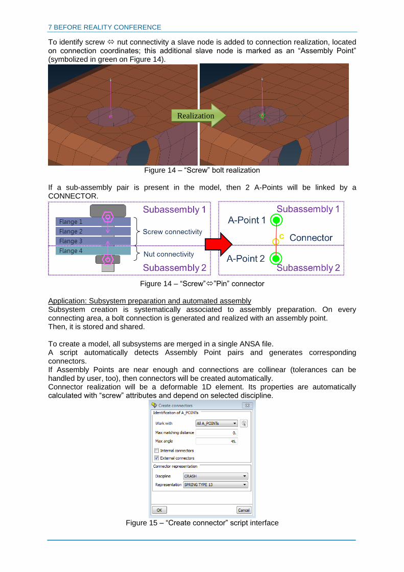
Application: Subsystem preparation and automated assembly Subsystem creation is systematically associated to assembly preparation. On every connecting area, a bolt connection is generated and realized with an assembly point. Then, it is stored and shared. To create a model, all subsystems are merged in a single ANSA file. A script automatically detects Assembly Point pairs and generates corresponding connectors. If Assembly Points are near enough and connections are collinear (tolerances can be handled by user, too), then connectors will be created automatically. Connector realization will be a deformable 1D element. Its properties are automatically calculated with “screw” attributes and depend on selected discipline.
Figure 15 – “Create connector” script interface
Realization

7 BEFORE REALITY CONFERENCE
6. NEXT STEP: ANSA / SIM MANAGER CONNECTOR New assembling process allows PSA to share subsystems and assembly data between all models. As PSA models validation is associated to official storage on Sim Manager (MSC Software), ongoing developments target is to create a connector between ANSA and Sim Manager. After these developments, update status and validation status will be available on ANSA, and ANSA DM Capabilities will allow users to update subsystems and assembly data automatically. 7. CONCLUSIONS Thanks to a strong partnership with BETA, PSA model assembly general process has been highly improved. ANSA allows PSA to anticipate input data availability for model creation and to automate assembly. Next step will be to develop a Sim Manager / ANSA connector to insure conformity check, automatic update of subsystems and simplified official storage of ANSA models and subsystems. REFERENCES (1) ANSA version 17.1.x User’s Guide, BETA CAE Systems, April 2017