psa-45d (e) · 2018-11-29 · 1o psa-45d (e) portable spectrum analyzer avcom of virginia 500...
TRANSCRIPT

1
PSA-45D (E) PORTABLE SPECTRUM ANALYZER
Avcom of Virginia 500 Southlake Blvd
Richmond, VA 23236 USA 804-794-2500
www.avcomofva.com
Owner’s Manual
2
AVCOM Publication No. PSA45D Revision 2.0
May 2007
TABLE OF CONTENTS
Inputs, Outputs, and Controls............................ 4 Initial Menu .......................................................... 9 Start-Up Menu ..................................................... 10 Operation Menu................................................... 17 Preliminary Operation......................................... 23 Band Aid Operation ............................................ 24 MFC Operation .................................................... 25 Specifications...................................................... 26 Frequency Allocation Charts ............................. 27 Frequency Reference Definitions ...................... 28 Warranty .............................................................. 29
AVCOM of Virginia 500 Southlake Blvd
Richmond, VA 23236 Phone (804) 794-2500
Fax (804) 794-8284 www.avcomofva.com
PSA-45D (E) - Owners Manual

3
PLEASE READ CAREFULLY BEFORE USING THE PSA-45D
GENERAL SAFETY WHEN USING INSTRUMENTS SUCH AS THE PSA-45D, POWER HAND TOOLS, AND ANY OTHER APPLIANCE CONNECTED TO AN ELECTRICAL OUTLET, EXERCISE GREAT CARE TO ENSURE THAT THE DEVICE IS GROUNDED EFFECTIVELY TO AVOID ELECTRICAL SHOCK. DO NOT USE WHILE STANDING IN WATER, ON DAMP EARTH, OR WHILE IN PERSONAL CONTACT WITH A CONDUCTING SURFACE SUCH AS A METAL LADDER OR CHAIR. ALSO: • USE PROPERLY GROUNDED ELECTRICAL OUTLET OR EXTENSION CORD • DO NOT CUT GROUNDING PIN FROM LINE CORD PLUG • USE FUSES OF CORRECT AMPERAGE • DISCONNECT LINE CORDS WHEN WORKING INSIDE RECEIVER OR ON ANTENNA • ENSURE THE ANTENNA AND OTHER COMPONENTS OF YOUR EARTH STATION ARE PROPERLY GROUNDED • DO NOT SERVICE EQUIPMENT ALONE—WORK WITH SOMEONE WHO CAN ADMINISTER HELP AND FIRST AID • PERSONS WORKING WITH LINE VOLTAGES SHOULD BE TRAINED IN AND CAPABLE OF PER-FORMING FIRST AID AND RESUSCITATION TECHNIQUES IMPORTANT CAUTIONS 1. The PSA-45D supplies +13/+18 VDC on the RF connectors to power most LNB's. It is the customers' responsibility to ensure that the components being powered by the PSA-45D are compatible with +13/+18 VDC. If in doubt, consult the manufacturer of the component. 2. Do not couple the input of the PSA-45D to high power RF sources such as walkie-talkies, CB radios, transmitters, etc. Signal levels in excess of +15 dBm can damage the sensitive mixers in the instrument resulting in otherwise unnecessary expense and repairs. External DC voltage not to exceed 50 VDC. 3. HANDLE WITH CARE- The PSA-45D Spectrum Analyzer is a precision instrument designed for normal operating and handling conditions. It should be protected from abuse such as dropping, throwing, and other rough handling. When being transported in a vehicle, or shipped, the PSA -45D must be cushioned and protected against shock and vibration.
4
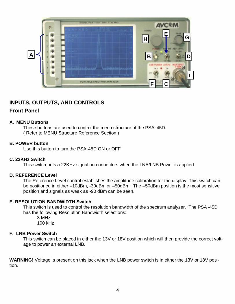
INPUTS, OUTPUTS, AND CONTROLS Front Panel A. MENU Buttons
These buttons are used to control the menu structure of the PSA-45D. ( Refer to MENU Structure Reference Section )
B. POWER button
Use this button to turn the PSA-45D ON or OFF C. 22KHz Switch
This switch puts a 22KHz signal on connectors when the LNA/LNB Power is applied
D. REFERENCE Level The Reference Level control establishes the amplitude calibration for the display. This switch can be positioned in either –10dBm, -30dBm or –50dBm. The –50dBm position is the most sensitive position and signals as weak as -90 dBm can be seen.
E. RESOLUTION BANDWIDTH Switch
This switch is used to control the resolution bandwidth of the spectrum analyzer. The PSA -45D has the following Resolution Bandwidth selections: 3 MHz 100 kHz
F. LNB Power Switch
This switch can be placed in either the 13V or 18V position which will then provide the correct volt-age to power an external LNB.
WARNING! Voltage is present on this jack when the LNB power switch is in either the 13V or 18V posi-tion.
A B
C
D
E
F
G H
I

5
G. SPAN WIDTH Knob Controls the sweep width of the Spectrum Analyzer/Monitor. When fully clockwise, signals in the entire bandwidth of the selected band are displayed. Then, if a smaller area of that spectrum is to be examined, the area is centered over the vertical centerline with the TUNING Knob and the SPAN control turned counterclockwise to see the signal more closely.
H. TUNING Knob
Tunes the PSA-45D through the selected band and centers signals of interest on the display while their frequency is shown at the top center of the display.
I. “N” Jack (950 — 2150 MHz)
The “N” jack is used to receive signals using an antenna, a cable, or a probe. This jack is the RF Input jack used in conjunction with the L-Band (950—2150 MHz) for the spectrum analyzer.
6
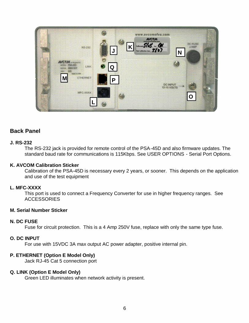
Back Panel J. RS-232
The RS-232 jack is provided for remote control of the PSA-45D and also firmware updates. The standard baud rate for communications is 115Kbps. See USER OPTIONS - Serial Port Options.
K. AVCOM Calibration Sticker Calibration of the PSA-45D is necessary every 2 years, or sooner. This depends on the application
and use of the test equipment L. MFC-XXXX
This port is used to connect a Frequency Converter for use in higher frequency ranges. See ACCESSORIES
M. Serial Number Sticker N. DC FUSE
Fuse for circuit protection. This is a 4 Amp 250V fuse, replace with only the same type fuse.
O. DC INPUT For use with 15VDC 3A max output AC power adapter, positive internal pin.
P. ETHERNET (Option E Model Only)
Jack RJ-45 Cat 5 connection port
Q. LINK (Option E Model Only) Green LED illuminates when network activity is present.
N
L
M
J K
O
P
Q

7
A. MENU Buttons
These buttons are used to control the menu structure of the PSA-45D.
B. MENU Structure This is the actual menu structure used in configuring the unit. As the MENU Buttons are pressed, the value, or menu structure will change accordingly.
C. MODEL Number
The value show in this position is the MODEL Number of the spectrum analyzer.
D. CENTER Frequency
This value is controlled by the TUNING Knob and represents the frequency at the center division of the screen.
I
A G
J
D C E F
H K L
B

8
E. SPAN Width The value of this is determined by the SPAN WIDTH Knob and shows the MHz/div chosen.
F. MENU SELECTION Value
This shows the value of the chosen menu selection. In the above reference, it shows the value of the screen contrast. As the CONTRAST + menu button is pressed, the value will increase.
G. AMPLITUDE The numbers on the right side of the screen depict the amplitude value in dB.
H. MINIMUM FREQUENCY Value
A value in this position shows the lower frequency value from the center line. It is derived from the Center Frequency — (Span Width/div X 4 Div)
I. TIME
This is the current time. J. CENTER Frequency
Center Frequency as determined by the TUNING Knob.
K. DATE This is the current date as set in the analyzer.
L. MAXIMUM Frequency A value in this position shows the upper frequency value from the center line. It is derived from the Center Frequency + (Span Width/div X 4 Div)

9
Button Label Description
M MENU Takes you to the standard menu structure of the ana-lyzer
1 only at startup Enters into a menu structure that is only available at the first boot of the spectrum analyzer.
2 Not Used
3 Contrast + Increases the value of screen contrast. Adjust for user preference.
4 Contrast — decreases the value of screen contrast. Adjust for user preference.
5 Not Used
6 Display of last software modifications date View only
7 Not Used
MENU STRUCTURE REFERENCE
INITIAL MENU: This menu is only seen on the initial boot of the spectrum analyzer

10
Button Label Description
M MENU>> -2 Changes to the next higher menu in the structure
1 MENU<< Changes to the next lower menu in the structure
2 Not Used
3 syncMode OFF
OFF (Default) / 60Hz / 50Hz Syncs the video signal to an internal 60Hz or 50Hz source.
4 freq counter Toggles Frequency Counter Display On or Off This affects the Frequency Counter display on the top and bottom of the analyzer screen
5 center_f trim_UP
User calibration of the center frequency
6 center_f trim_DOWN
User calibration of the center frequency
7 mode Used only in conjunction with an AVCOM MFC See Frequency Extender Operation Section
MENU STRUCTURE REFERENCE
STARUP MENU: 2
11
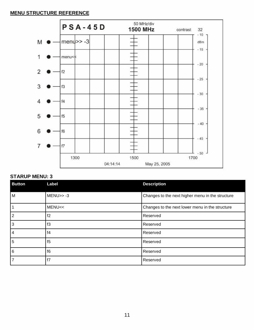
Button Label Description
M MENU>> -3 Changes to the next higher menu in the structure
1 MENU<< Changes to the next lower menu in the structure
2 f2 Reserved
3 f3 Reserved
4 f4 Reserved
5 f5 Reserved
6 f6 Reserved
7 f7 Reserved
MENU STRUCTURE REFERENCE
STARUP MENU: 3

12
Button Label Description
M MENU>> -4 Changes to the next higher menu in the structure
1 MENU<< Changes to the next lower menu in the structure
2 Not Used
3 Not Used
4 show dB+X dB Offset — used to enter a known offset for cable length attenuation. Non-volatile setting
5 increase X Increases dB Offset by 1dB
6 decrease X Decrease dB Offset by 1 dB
7 Sound ON/off Turns sound On (Default) or Off
MENU STRUCTURE REFERENCE
STARUP MENU: 4

13
Button Label Description
M MENU>> -5 Changes to the next higher menu in the structure
1 MENU<< Changes to the next lower menu in the structure
2 frequency markers on/OFF
Displays a vertical marker created at the current cen-ter frequency setting.
3 select/info User selectable markers from 0—15 for a total of 16 markers
4 . . Create Creates a marker in the selected marker location
5 . . Remove Removes the marker from the selected marker loca-tion
6 near cf remove
Removes all markers in within the first division on ei-ther side of the center frequency line
7 Save info Saves the frequency marker information
MENU STRUCTURE REFERENCE
STARUP MENU: 5
14
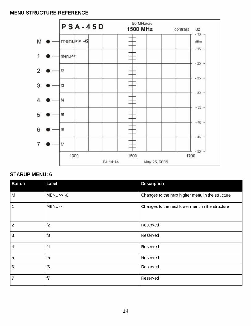
Button Label Description
M MENU>> -6 Changes to the next higher menu in the structure
1 MENU<< Changes to the next lower menu in the structure
2 f2 Reserved
3 f3 Reserved
4 f4 Reserved
5 f5 Reserved
6 f6 Reserved
7 f7 Reserved
MENU STRUCTURE REFERENCE
STARUP MENU: 6
15
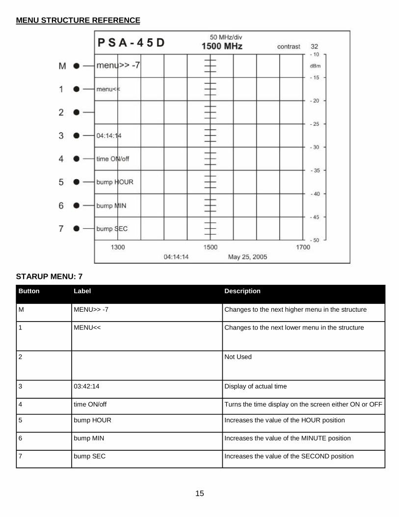
Button Label Description
M MENU>> -7 Changes to the next higher menu in the structure
1 MENU<< Changes to the next lower menu in the structure
2 Not Used
3 03:42:14 Display of actual time
4 time ON/off Turns the time display on the screen either ON or OFF
5 bump HOUR Increases the value of the HOUR position
6 bump MIN Increases the value of the MINUTE position
7 bump SEC Increases the value of the SECOND position
MENU STRUCTURE REFERENCE
STARUP MENU: 7
16
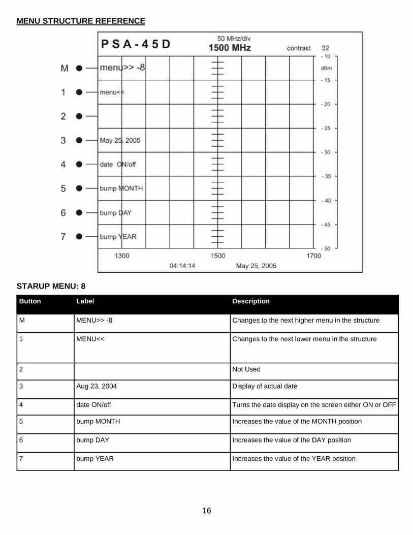
Button Label Description
M MENU>> -8 Changes to the next higher menu in the structure
1 MENU<< Changes to the next lower menu in the structure
2 Not Used
3 Aug 23, 2004 Display of actual date
4 date ON/off Turns the date display on the screen either ON or OFF
5 bump MONTH Increases the value of the MONTH position
6 bump DAY Increases the value of the DAY position
7 bump YEAR Increases the value of the YEAR position
MENU STRUCTURE REFERENCE
STARUP MENU: 8

17
Button Label Description
M next menu m0:
Changes to menu 1
1 traceA->B Freezes the current trace to the background
2 hide B / view B Removes background trace / Displays last background trace.
3 hide A / view A Removes active trace from the display / Shows the active trace on the display.
4 PeakHold persistent—unlimited—short—until f3 hit
Causes the active display to hold the peak of the trace for a set amount of time.
5 disp line UP
Adjusts the user controlled marker for dB level UP 2dB
6 disp line DOWN
Adjusts the user controlled marker for dB level DOWN 2dB
7 disp line ctrl off—course—fine
Display line OFF Course—Adjusts the display line by 2 dB steps Fine—Adjusts the display line by 1 dB steps
MENU STRUCTURE REFERENCE
OPERATION MENU: 0

18
Button Label Description
M next menu m1:
Changes to menu 2
1 mem 01 Non-Volatile memory locations to save trace informa-tion. Used to Recall or Save active screen traces.
2 mem 02
3 mem 03
4 mem 04
5 mem 05
6 next five Up to 50 memory locations
7 save to 01 Saves trace to current location
MENU STRUCTURE REFERENCE
OPERATION MENU: 1

19
Button Label Description
M next menu m2:
Changes to menu 3
1 show dBm Default display of reading on the right of the analyzer screen
2 show dBmv Changes right display to dBmv for specific applications
3 mode dB normal / hidden / adding X / hiding +X
Determines display and value displayed in dB on right of analyzer screen Adding X and hiding +X show the values with X Offset as entered in STARTUP MENU:4
4 grids ctrl Toggles Grid display ON/OFF
5 disp line UP
Adjusts the user controlled marker for dB level UP 2dB
6 disp line DOWN
Adjusts the user controlled marker for dB level DOWN 2dB
7 disp line ctrl
Display line OFF Course—Adjusts the display line by 2 dB steps Fine—Adjusts the display line by 1 dB steps
MENU STRUCTURE REFERENCE
OPERATION MENU: 2
20
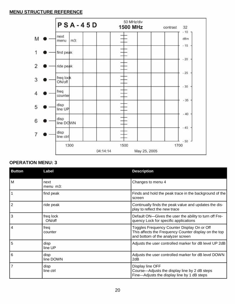
Button Label Description
M next menu m3:
Changes to menu 4
1 find peak Finds and hold the peak trace in the background of the screen
2 ride peak Continually finds the peak value and updates the dis-play to reflect the new trace
3 freq lock ON/off
Default ON—Gives the user the ability to turn off Fre-quency Lock for specific applications
4 freq counter
Toggles Frequency Counter Display On or Off This affects the Frequency Counter display on the top and bottom of the analyzer screen
5 disp line UP
Adjusts the user controlled marker for dB level UP 2dB
6 disp line DOWN
Adjusts the user controlled marker for dB level DOWN 2dB
7 disp line ctrl
Display line OFF Course—Adjusts the display line by 2 dB steps Fine—Adjusts the display line by 1 dB steps
MENU STRUCTURE REFERENCE
OPERATION MENU: 3
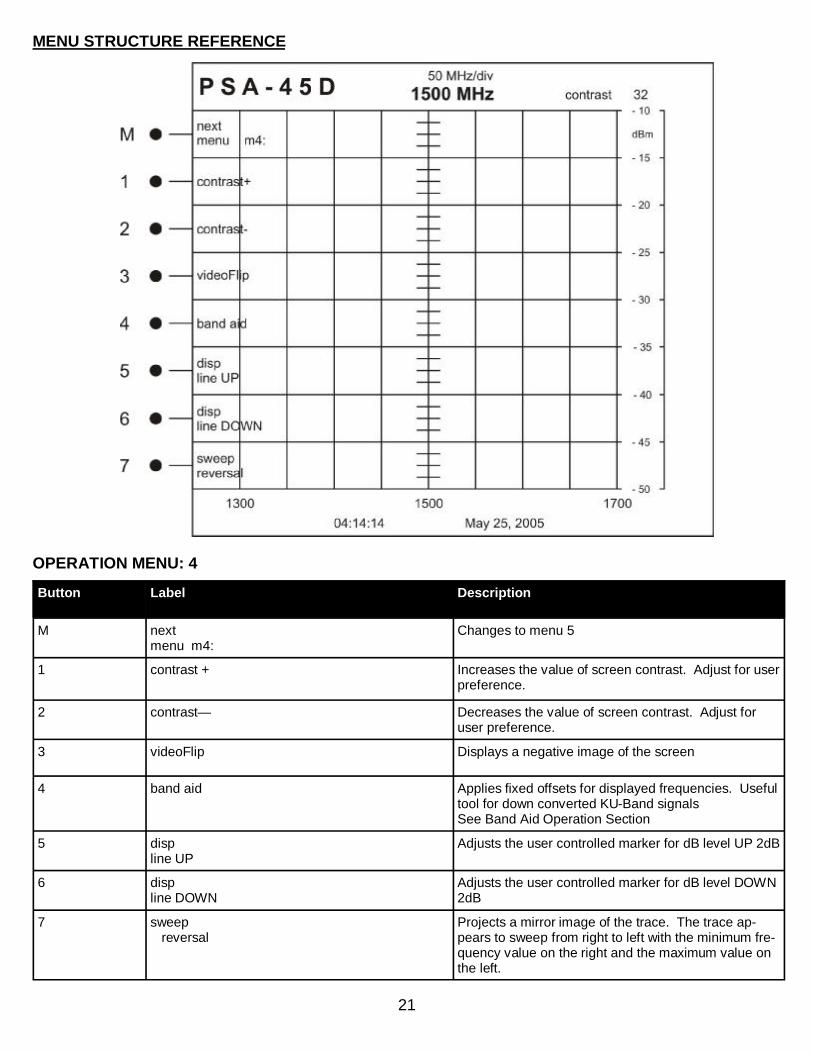
21
Button Label Description
M next menu m4:
Changes to menu 5
1 contrast + Increases the value of screen contrast. Adjust for user preference.
2 contrast— Decreases the value of screen contrast. Adjust for user preference.
3 videoFlip Displays a negative image of the screen
4 band aid Applies fixed offsets for displayed frequencies. Useful tool for down converted KU-Band signals See Band Aid Operation Section
5 disp line UP
Adjusts the user controlled marker for dB level UP 2dB
6 disp line DOWN
Adjusts the user controlled marker for dB level DOWN 2dB
7 sweep reversal
Projects a mirror image of the trace. The trace ap-pears to sweep from right to left with the minimum fre-quency value on the right and the maximum value on the left.
MENU STRUCTURE REFERENCE
OPERATION MENU: 4
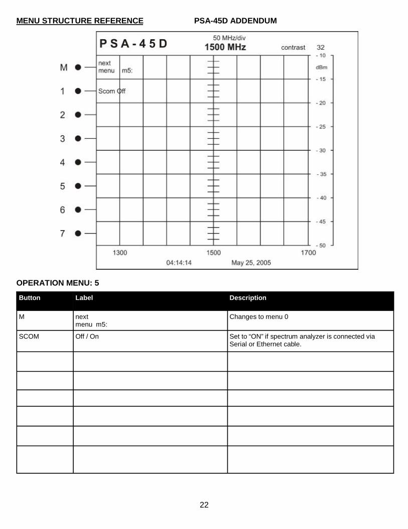
22
Button Label Description
M next menu m5:
Changes to menu 0
SCOM Off / On Set to “ON” if spectrum analyzer is connected via Serial or Ethernet cable.
MENU STRUCTURE REFERENCE
OPERATION MENU: 5
PSA-45D ADDENDUM

23
OPERATION
Preliminary Checkout and User Familiarization 1. Plug the PSA-45D into a line socket using an AC adapter (input: 100-240VAC 1.5A 50-60Hz, output:
15VDC 3A). 2. Press the POWER botton, the front unit should power on. 3. Observe the Power On Self Test on the display quickly followed by the STARTUP MENU Screen 4. Place LNB PWR switch to the 18V position. Note red LED light, indicating that +18 VDC is available
on RF connector. 5. Place LNB PWR switch to the 13V position. Note red LED light, indicating that +13 VDC is available on
RF connector. 6. Place LNB PWR switch to the OFF position. Note red LED light is off. 7. Set up instrument as follows:
BAND SELECT: L-Band (950-2150 MHz) RESOLUTION BW: 3 MHz Options: 100 KHz REFERENCE LVL: -10 dBm Options: -30 dBm -50 dBm CENTER FREQUENCY: Use TUNING to set frequency at 1500 MHz SPAN: fully clockwise
8. Using the TUNING Control, tune to signal in the center of the display. 9. Turn the SPAN control slowly counterclockwise to expand the signal, while keeping it centered with the TUNING control. Expand the large peak significantly and center it. 10. To check that the sensitivity of the instrument can be changed with the REFERENCE Level control, observe the SIGNAL and turn REFERENCE LEVEL to –30 dBm. The peak should become larger. Then turn REFERENCE LEVEL to –50 dBm. The little peaks to the sides of the main peak should become higher and the main trace should become noticeably noisy. This completes the User Familiarization and Preliminary Checkout procedure.

24
OPERATION
BAND AID INTRODUCTION AND SETUP The PSA-45D has a built in feature for viewing down-converted KU-Band. Normally, the KU-Band fre-quencies are stepped down to L-Band frequencies and displayed on the analyzer. With the BAND AID Function, you will be able to view the frequencies on the frequency counter as they truly are. The PSA -45D has implemented this feature to aid in the field installation processes utilizing the AVCOM portable spectrum analyzers. SETUP PROCEDURE 1. Place the BAND SELECT knob in the L-BAND position (950—2150MHz). The Band Aid feature is
disabled in all other BAND positions. 2. Adjust the SPAN WIDTH, RESOLUTION BANDWIDTH, REFERENCE LEVEL, and TUNING KNOB to
view the desired signal. 3. Press the M button and navigate to MENU M4. 4. Press the M4 Button to initialize BAND AID.
4.1 Pressing the M4 Button once adds the 11700 + offset to the shown frequency. 4.2 Pressing the M4 Button again will add the 11300 + offset to the shown frequency. 4.3 Pressing the M4 Button again will add the 10750 + offset to the shown frequency. 4.4 Pressing the M4 Button again will allow you to set a custom offset to the shown frequency.
5. View the changes to the frequency counter with the offset inserted. 6. These values are non-volatile and will be lost when the PSA-45D is turned off.

25
OPERATION
MFC INTRODUCTION AND SETUP All AVCOM Portable Spectrum Analyzers have the ability to extend their base frequency with the use of an MFC (Microwave Frequency Con-verter). When using an MFC, the frequency is stepped down to a level that can be viewed by the analyzer, and the frequency readouts are auto-matically corrected through the communication protocols between the MFC and the analyzer. Each MFC is manufactured for a specific ana-lyzer and can not be interchanged, however, the AVCOM MFC can be developed for any manufacturer model of spectrum analyzers. Please contact AVCOM Customer Care for more information. SETUP PROCEDURE 1. Plug the supplied, flat, rollover cable into the back port of the MFC. This cable is made specifically for
this application and cannot be substituted. 2. Plug the other end of this cable into the MFC-XXXX port of the spectrum analyzer. 3. Plug the supplied, N-Type Cable into the MFC Output jack. 4. Plug the other end of the N-Type Cable into the input of the spectrum analyzer. 5. The analyzer will recognize the MFC and make all necessary changes to the display.
26
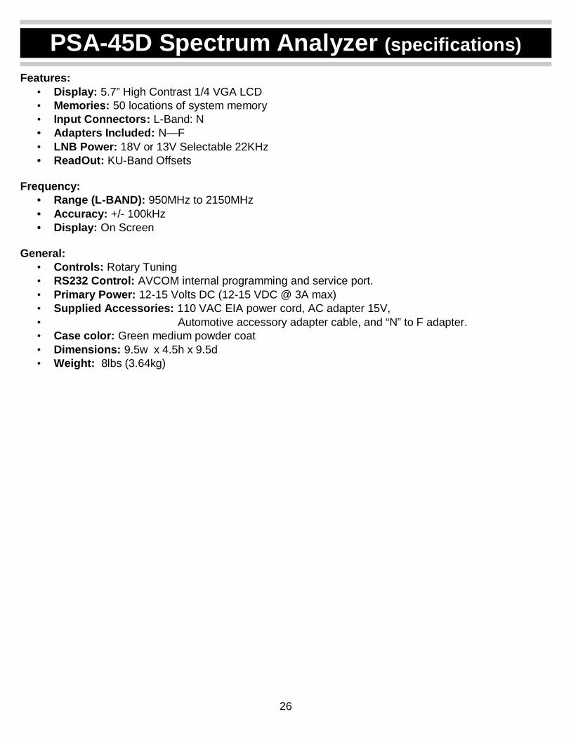
Features: • Display: 5.7” High Contrast 1/4 VGA LCD • Memories: 50 locations of system memory • Input Connectors: L-Band: N • Adapters Included: N—F • LNB Power: 18V or 13V Selectable 22KHz • ReadOut: KU-Band Offsets
Frequency:
• Range (L-BAND): 950MHz to 2150MHz • Accuracy: +/- 100kHz • Display: On Screen
General:
• Controls: Rotary Tuning • RS232 Control: AVCOM internal programming and service port. • Primary Power: 12-15 Volts DC (12-15 VDC @ 3A max) • Supplied Accessories: 110 VAC EIA power cord, AC adapter 15V, • Automotive accessory adapter cable, and “N” to F adapter. • Case color: Green medium powder coat • Dimensions: 9.5w x 4.5h x 9.5d • Weight: 8lbs (3.64kg)
PSA-45D Spectrum Analyzer (specifications)
27
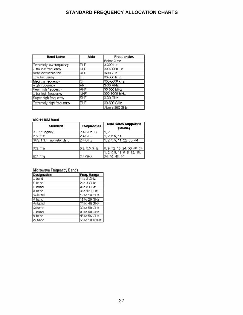
STANDARD FREQUENCY ALLOCATION CHARTS

28
KEY DEFINITIONS
Extremely low frequency or ELF refers to the band of radio frequencies from 3 to 300Hz. Very low frequency or VLF refers to radio frequencies (RF) in the range of 3 to 30 kHz. Low Frequency or LF refers to Radio Frequencies (RF) in the range of 30-300 kHz. Medium frequency or MF refers to radio frequencies (RF) in the range of 300 -3000 kHz. High frequency (HF) radio frequencies are between 3 and 30 MHz. Very high frequency (VHF) is the radio frequency range from 30 MHz to 300 MHz. Common uses for VHF are FM radio broadcast at 88-108 MHz and television broadcast.
Ultra high frequency (UHF) radio frequencies are those between 300 MHz and 3.0 GHz. Extremely high frequency is the highest radio frequency band included in the range of frequencies from 30 to 300 gigahertz. IEEE 802.11 or Wi-Fi is a set of Wireless LAN standards developed by working group 11 of IEEE 802. This includes three separate versions: 802.11a operates at 5.2GHz and 5.5GHz, 802.11B operates at 2.4GHz and 802.11G operates at 2.4GHz. L band a portion of the microwave band of the electromagnetic spectrum ranging roughly from 950 MHz to 2.5 GHz. It is used by some communications satellites. S band a part of the microwave band of the electromagnetic spectrum ranging roughly from 1.55 to 5.2 GHz where 2.3 GHz is currently used by Sirius Satellite Radio and XM Satellite Radio. C band a portion of electromagnetic spectrum in the microwave range of frequencies ranging from 4 to 6 GHz. C band is primarily used for satellite communications, normally downlink 3.7 –4.2 GHz horizontal polarization, uplink 5.9–6.4 GHz vertical polarization, X band in the microwave band of the electromagnetic spectrum roughly ranges from 5.2 –10.9 GHz. K band a portion of the electromagnetic spectrum in the microwave range of frequencies ranging between 12 to 40 GHz. The Ka band a portion of the K band of the microwave band of the electromagnetic spectrum ranging from 18 to 40 GHz. The Ku band a portion of the electromagnetic spectrum in the microwave range of frequencies ranging from 11 to 18 GHz. Ku band is primarily used for satellite communications.

29
TERMS AND CONDITIONS
Only the following terms and conditions apply to the sale and delivery of the goods reflected herein. The products manufactured by AVCOM OF VIRGINIA INC., (hereafter referred to as AVCOM) are subject to the following conditions and are subject to change without prior written notice at AVCOMS’ sole discretion. All implied warranties, if any, terminate 1 year from the date of the original purchase. LIMITED WARRANTY POLICY AVCOM warrants to the original purchaser that this product shall be free from defects in materials and workmanship upon delivery. AVCOM additionally warrants that product, used under normal service conditions, shall be free from defects in materials and workmanship for a period of 1 year. The warranty policy includes:
• Labor cost and replacement of original parts and components. • Shipping charges on units within the first 60 days of purchase. • Repair cycle time of 7 business days upon return of unit to the factory Customer
Service Center. Dead on Arrival (DOA) units will be given top priority and covered by the above policies with the exception of a 72 hour repair cycle time upon return to the factory Customer Service Center. THIS WARRANTY DOES NOT INCLUDE batteries, cathode ray tubes or LCD displays. AVCOM cannot control the environment or usage of these components and therefore the customer is solely responsible for any cost of labor or material in conjunction with their maintenance and/or replacement. AVCOM shall not be liable for cost of repairs or replacement of parts or components due to physical damage, product misuse or abuse and unauthorized modifications or repair. To receive In-Warranty service, the defective product must be received no later than the specified warranty period by contacting AVCOMS’ Customer Service center for a Return Material Authorization (RMA) number. Information needed to process the RMA includes the Model number, Serial number, date and place of purchase. For an RMA number contact AVCOM Service Center at PHONE: (804)-794-2500 or FAX (804) 794-8284. No product will be accepted by AVCOM that does not have an RMA number. Extended warranty information is available at AVCOM Factory Headquarters, 500 Southlake Boulevard, Richmond, Virginia 23236 PHONE: (804) -794-2500.