ps 2808e/ep - elhvb€¦ · ps 2808e/ep user manual 2 item checklist prior to beginning the...
TRANSCRIPT

PS 2808E/EP User Manual
1
PS 2808E/EP User Manual
Copyright 2001 Publishing. All rights reserved. This manual, software and firmware described in it are copyright by their respective owners and protected under the laws of the Universal Copyright Convention. You may not reproduce, transmit, transcribe, store in a retrieval system, or translate into any language, in any form or by any means, electronic, mechanical, magnetic, optical, chemical, biological, molecular, manual, or otherwise, any part of this publication without the express written permission of the publisher. All products and trade names described within are mentioned for identification purpose only. No affiliation with or endorsement of the manufacturer is made or implied. Product names and brands appearing in this manual are registered trademarks of their respective companies. The information published herein has been checked for accuracy as of publishing time. No representation or warranties regarding the fitness of this document for any use are made or implied by the publisher. We reserve the right to revise this document or make changes in the specifications of the product described therein at any time without notice and without obligation to notify any person of such revision or change.
Printed in Poland

PS 2808E/EP User Manual
2
Item Checklist Prior to beginning the installation of your mainboard, please insure that the following materials have been provided:
• One PS 2808E/EP main board. • This user manual. • One Floppy disk drive cable. • One Ultra DMA/100 IDE cable. • One Software & Utility Pack CD.
If any of the above items are either damaged or missing, please contact your retailer.
PS 2808E/EP Mainboard
Floppy Disk Drive Cable
Ultra DMA/100 IDE Cable
PS 2808E/EP Manual
Software & Utility Pack CD

PS 2808E/EP User Manual
3
Contents 1 Introduction 1-1 Introduction 4 1-2 Specifications 5 1-3 Main Board Layout 7 2 Installation Procedures 2-1 Setting System Jumpers 9 2-2 System Memory (DIMM) 10 2-3 Central Processing Unit (CPU) 11 2-4 Expansion Cards 13 2-5 External Connectors 14 2-6 Power Connection Procedures 18 3 Award BIOS Setup 3-1 Introduction 19 3-2 Main Menu 22 3-3 Standard CMOS Features 24 3-4 Advanced BIOS Features 28 3-5 Advanced Chipset Features 33 3-6 Integrated Peripherals 36 3-7 Power Management Setup 39 3-8 PnP/PCI Configurations 43 3-9 Defaults Menu 45 3-10 PC Health Status 46 3-11 Frequency/Voltage Control 47 3-12 Password Setting 48 3-13 Exit Selecting 48 Wersja Polska 45
PS 2808E/EP User Manual
4
Chapter 1 Introduction
1-1 Introduction This mainboard contains the 815E or 815EP chipset from Intel (www.intel.com). The Intel 815E and 815EP chipsets unleash the full performance potential of Intel’s Celeron and Pentium III Socket 370 processors by providing an extensive high-end feature-set that includes 133MHz FSB, AGP4X, PC133 memory and ATA-100. The Best Choice for Intel Socket 370 Processors The Intel 815E and 815EP are the first chipsets available supporting the new Intel Pentium III Tualatin Socket 370 processors. Building on the success of the Intel 440BX chipset, the Intel 815E and 815EP chipsets support the same high-end features:
Blistering AGP4X Graphics Performance The Intel 815E and 815EP support AGP4X, the latest high-performance graphics bus technology, on the Intel Celeron and Pentium III processor platform. The AGP4X interface enables the graphics controller to access the main memory at double the speed of previous platforms, ensuring rich 3D graphics and video performance on your Intel Celeron or Pentium III processor-based PC system. High-Speed PC133 Memory Through its advanced memory controller architecture, the Intel 815E and 815EP chipsets support up to 1.5G of the latest high-speed PC133 SDRAM and VC133 DRAM. These leading-edge memory technologies provide the bandwidth and performance necessary for even the most demanding Internet and 3D graphics applications at a minimal cost premium over PC100 SDRAM. Ultra-Fast 133MHz Front Side Bus With its 133MHz Front Side Bus, the Intel 815E and 815EP chipsets help boost system performance by providing a high-speed connection to the new generation of ATA-100 Hard Disk Drives, delivering maximum sustained data transfer rates of 100MB/sec.
This manual is designed for reference only. It is not a training guide for new users for system assembly. Only trained technicians should install and setup a computer system. Warranty for this board does not cover improper installations!
PS 2808E/EP User Manual
5
1-2 Specifications
CPU
- Intel Socket 370 Pentium III processors from 500MHz to >1GHZ. 256K second level cache on die.
- Intel Socket 370 Celeron processors from 600MHz to >900MHz. 128K second level cache on die.
Chipset - Intel 815E or 815EP, consisting of: - 82815 (815E) or 82815EP (815EP) North Bridge Controller - 82801BA South Bridge Controller.
Memory - 3 × 168-pin DIMM Sockets. - Supports 100MHz & 133MHz SDRAM 32MB~1.5GB. - Supports 3.3V SDRAM DIMM. - Supports SDRAM, VCM SDRAM memory types.
Optional Audio - SoundBlaster Pro Compatible Hardware and Direct Sound Ready
AC97 Digital Audio Controller. - Hardware SoundBlaster Pro for Windows DOS box and real-
mode DOS legacy compatibility. - Supports two-channel speaker mode. - MPU-401 game/MIDI port and SoundBlaster 16 compatible.
I/O Control - Integrated Super I/O Controller in the 82801BA.
Expansion Slot - Six 32-bit PCI slots support Master mode & PCI 2.2 compliant. - One AGP slot supports 4X mode & AGP 2.0 compliant. - One CNR (Communication Network Riser) slot.
I/O Interface - PCI Bus master IDE interface on board with two connectors
supports 4 IDE devices in 2 channel, the PCI IDE Controller supports PIO Mode 0 to 4, Bus master IDE DMA Mode 2 and Ultra DMA 33/66/100.
- On board super Multi-I/O chip that support 2 serial ports, 1 parallel with ECP capabilities, and a floppy disk drive interface.
- On board support PS/2 mouse connector. - On board support PS/2 keyboard connector.

PS 2808E/EP User Manual
6
- On board 4 USB ports. (2 external ports & 2 internal pin header) - On board IrDA connector. - Floppy port supports 2 FDD with 360K, 720K, 1.2M, 1.44M &
2.88M bytes. Supports LS-120 floppy disk device. Other Function
- Supports Modem Ring Power On. - Supports Wake On LAN.
Power Supply - On board 3V, 5V and 12V 20-pin ATX power connector. - Use switching regulator to support CPU core voltage.
Optional Hardware Monitoring - CPU/Power Supply/Chassis Fan Revolutions detecting. - CPU Fan Control. - System Voltage Detect. - Display Current Voltage.
BIOS - Licensed AWARD BIOS, 2/4M bit FLASH RAM. - ACPI ready for PC98/Windows 98. - System BIOS supports ACPI function and Green feature function,
DMI, Plug & Play Flash ROM. Form Factor
- ATX Form Factor. - Dimensions 305mm × 190mm. - 4 layer PCB.
Drivers - Intel Driver Service Pack

PS 2808E/EP User Manual
7
1-3 Mainboard Layout
PS 2808E/EP User Manual
8
Chapter 2 Installation Procedures Warning: Always disconnect the power cord from your computer whenever
your are working on it. Failure to do so may result in sensitive electronic components being damaged.
Note: Always ground yourself to remove any static charge before
touching any electronic components in the system. Place all electronic components on a static free surface or in an anti static bag when they are not being handled or installed in the computer.
User adjustable jumpers have been installed on the mainboard to allow for user configuration of the mainboard to meet your specific needs. Information pertaining to all jumper configurations has been included in the following chapter. To correctly install your mainboard into your computer, use the following steps:
1. Set the jumpers on your mainboard to the correct configuration. 2. Install RAM. 3. Install CPU & Fan. 4. Install expansion cards. 5. Locate and install external devices. 6. Perform power on procedures.

PS 2808E/EP User Manual
9
2-1 Setting System Jumpers Warning: Incorrect jumper configurations may damage the CPU, the
mainboard and other sensitive electronic components. It is advisable to consult product literature before configuring the jumpers on the PS 2808E/EP mainboard.
The PS 2808E/EP mainboard has five jumpers (JP1, JP2, JP4, JP5 & JP6) that enable the user to set-up the mainboard for optimal performance based on their computing needs. A jumper is the simplest type of electrical switch. It consists of two metal pins and a metal clip, which is covered by a plastic cover. You may set up you mainboard to match the needs of your applications by setting the jumpers. To open a jumper, you remove the clip. To close a jumper, you connect the pins by using the clip.
The jumper settings are presented above. JP1 – Setup the Keyboard Wake Up function
1,2 – factory setting – disable keyboard wake up function 2,3 – enable keyboard wake up function
JP2 – Setup the FSB clock
Open – factory setting - setting clock on 100/133MHz Close – setting clock on 66MHz
JP4 – Setting up the AC97 On Board Sound function:
Open – factory setting – enable AC97 on board Close – disable AC97 on board
PS 2808E/EP User Manual
10
JP5 – Setup the USB Wake Up function
1,2 – factory setting – disable the USB Wake Up function 2,3 – enable the USB Wake Up function
JP6 – Clearing CMOS Setup
1,2 – factory setting – keeping the BIOS setting 2,3 – Clearing the CMOS setup
In order to clear the data stored in the CMOS, first turn off the computer and remove the power cord. Next, ground yourself and locate JP2 on you mainboard. Then remove the jumper from pins 2 & 3 and place the jumper on pins 1 & 2 (3V battery back up). Reattach the power cord and restart the computer.
2-2 System Memory
The PS 2808E/EP mainboard can support up to 1.5GB of 100MHz or 133Mhz SDRAM. Installing memory modules requires no system setup what so ever. Note:
1. The PS 2808E/EP mainboard can only accommodate DIMMs (Dual Inline Memory Modules). The DIMM sockets on the PS 2808E/EP are for 3.3V (power level) SDRAM (Synchronous Dynamic Random Access Memory).
2. Due to the strict timing issues involved under this speed, you must insure that SDRAM is 100/133MHz compliant.
Installing System Memory Insert the DIMM as illustrated in the diagram below. Due to the number of pins between each of the breaks in the module, the DIMM will only fit into the socket one way. Please insure that the DIMMs that you are using are 3.3V. To insert the DIMM into the socket, first the DIMM socket levers (the white levers on either side of the DIMM socket) must be pushed out away from the socket itself. Then line up the pins on the DIMM to the corresponding pins in the socket. Push the DIMM securely down into the socket. As the DIMM

PS 2808E/EP User Manual
11
slides into the socket, the DIMM socket levers will snap back in toward the DIMM socket securing the DIMM into place.
2-3 CPU (Central Processing Unit) The PS 2808E/EP mainboard is a Socket 370 mainboard. This refers to 370-pin socket that the board utilizes to accommodate the CPU. The CPU that is in use or you are going to use should have a cooling fan attached to it to prevent overheating. If your CPU does not have a fan, please ensure that you purchase and install a CPU cooling fan prior to turning on your computer for the first time. After installing the cooling fan, make sure that there is sufficient airflow around the fan to ensure proper cooling. If there is insufficient air circulation, the processor can overheat and damage not only the CPU, but also the mainboard. Caution: The faster your processor is, the more heat it. A suitable cooling
fan for your specific processor must be used.

PS 2808E/EP User Manual
12
CPU Installation Procedures Step1 Open the socket by raising the actuation lever. Step 2 Insert the processor. Ensure proper pin 1 orientation by aligning the FC-PGA corner marking with the socket corner closest to the actuation arm tip. The pin field is keyed to prevent mis-oriented insertion. Do not force the processor into the socket. If it does not go in easily, check for mis-orientation and debris. Make sure the processor is fully inserted into the socket on all sides. Step 3 Close the socket by closing the actuation lever.
PS 2808E/EP User Manual
13
2-4 Expansion Cards Warning: Always disconnect the power cord from your computer whenever
your are working on it. Failure to do so may result in sensitive electronic components being damaged.
Note: Always ground yourself to remove any static charge before
touching any electronic components in the system. Place all electronic components on a static free surface or in an anti static bag when they are not being handled or installed in the computer.
The PS 2808E/EP mainboard has 1 AGP, 6 PCI & 1 AMR expansion slots. To install an AGP, PCI or AMR card, please follow the following procedure:
1. Read any documentation that is accompanied with the expansion card.
2. Ensure that any hardware setup such as jumper configuration has been completed.
3. Remove the computer cover and unscrew and remove the bracket plate that accompanies the slot to which you want to install the expansion card into.
4. With great care align the card connectors with the socket connectors and press the expansion card firmly into place.
5. Secure the card by replacing the screw from the bracket plate. Replace the computer cover.
6. Perform any BIOS updating necessary. 7. Install any drivers and/or software necessary for the operation of
your expansion card.

PS 2808E/EP User Manual
14
2-5 External Connectors
1 2 3 45A 5B 67A 7B 7C 1. PS/2 Mouse Connector: The PS 2808E/EP mainboard has a built in mini-DIN mouse connector, which is designed for a PS/2 style mouse. 2. PS/2 Keyboard Connector: The PS 2808E/EP mainboard has a built in mini-DIN keyboard connector, which is designed for a PS/2 style keyboard. This connector will not accommodate a standard AT (large-DIN) keyboard plug. 3. USB Ports 1 & 2 (Universal Serial BUS): The PS 2808E/EP mainboard has two build in USB ports. 4. Parallel Port Connector: The PS 2808E/EP mainboard has a built in parallel port, which is used to connect the computer to the printer. 5. Serial Ports COM1 & COM2: The PS 2808E/EP mainboard has two built in serial ports. The COM1 & COM2 ports are ready for a mouse or other serial devices. 6. Optional Joystick/MIDI Connector: The PS 2808E/EP mainboard has an optional built in Joystick/MIDI connector that allows you to connect joysticks or game pads to your computer. You can also use this connector for connecting MIDI devices for playing and editing audio. 7. Optional Audio Port Connectors: The PS 2808E/EP mainboard has three optional built in 1/8” Game-Audio connectors. The optional Line Out is designed to be connecting to either headphones or powered speakers. The optional Line In is designed to allow your computer to record or play from external sources such as CD player or other audio source. The optional Mic In is designed to be connecting to a microphone to allow the inputting of voices into the system.
PS 2808E/EP User Manual
15
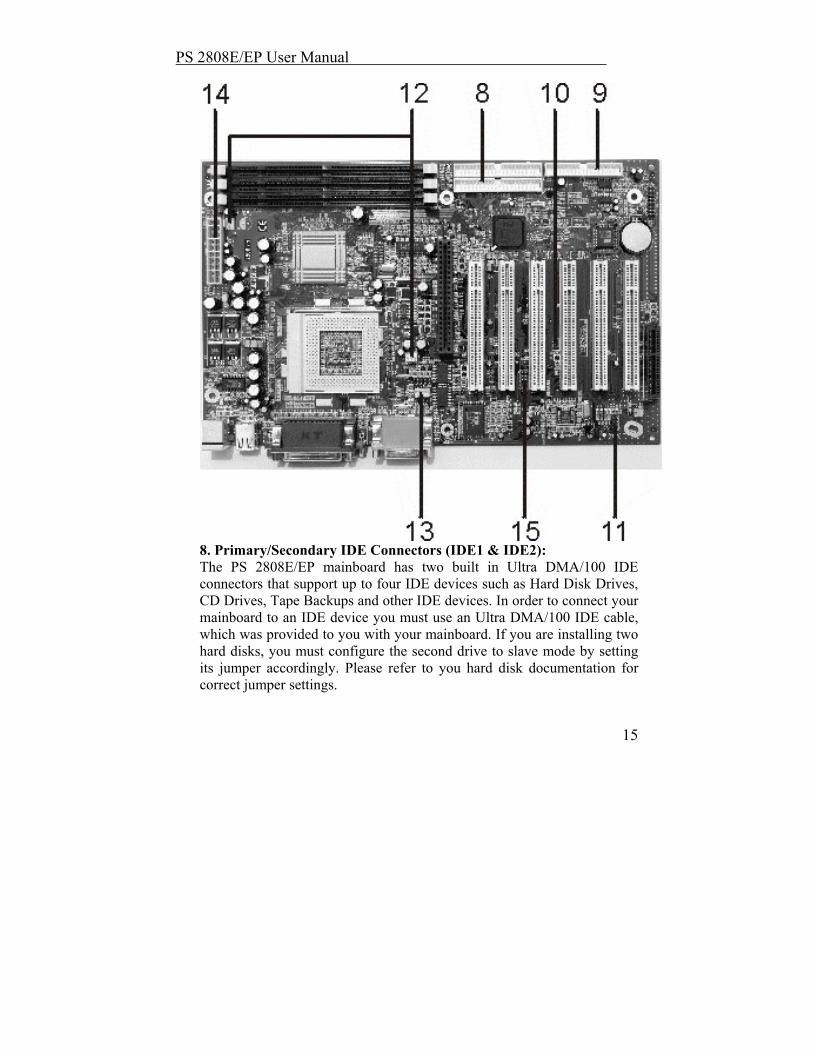
8. Primary/Secondary IDE Connectors (IDE1 & IDE2): The PS 2808E/EP mainboard has two built in Ultra DMA/100 IDE connectors that support up to four IDE devices such as Hard Disk Drives, CD Drives, Tape Backups and other IDE devices. In order to connect your mainboard to an IDE device you must use an Ultra DMA/100 IDE cable, which was provided to you with your mainboard. If you are installing two hard disks, you must configure the second drive to slave mode by setting its jumper accordingly. Please refer to you hard disk documentation for correct jumper settings.

PS 2808E/EP User Manual
16
9. Floppy Disk Drive Connector (FDC): The PS 2808E/EP mainboard has a built in Floppy Disk Drive Connector that allows up to two floppy drives to be connected to the mainboard. In order to connect your mainboard to a floppy drive you must connect it using the floppy disk drive cable that was provided to you with your mainboard. The drive A:\ should be connected at the end of the cable and if you have a second floppy drive, drive B:\ should be connected in the middle of the cable. 10. Wake On LAN (WOL)/Wake On Modem (WOM) Connector (WOL1): The PS 2808E/EP mainboard has a built in Wake On LAN and Wake On Modem connector. This connector allows the system to power up when a wakeup packet or signal is received through the LAN/modem card. 11. USB2 PIN Header (Universal Serial Bus 2): The PS 2808E/EP mainboard has a built in connector for two additional USB ports by means of a USB PIN Header. 12. CPU/AGP Fan Connectors (Fan1 & Fan2): The PS 2808E/EP mainboard has two built in fan connectors for connecting up to two cooling fans to the mainboard. One fan should always be used for cooling your CPU, while another fan connector could be utilized for an AGP card cooling fan or a chassis fan or not at all. Depending upon the type of fan that you have, the wiring and the plug may be different. Usually, but not always, the red is positive, while the black is ground. Connect the fan plug to the board while ensuring to connect the positive pin to the positive pin and the negative pin to the negative pin. 13. Internal Audio Connectors: These two connectors allow direct stereo input into your mainboard from such sources as a CD-ROM, a TV-Tuner and/or an MPEG Card. 14. ATX Power Connector: This connector connects the PS 2808E/EP mainboard to the ATX power supply in your computers chassis. The ATX power connector can only be inserted one way, so to insert the ATX power connector, line up the pins and push down firmly. 15. IR1,2 (IR Pin Header): The PS 2808E/EP has an IR (Infrared) connector for use with IR modules. You can connect your mainboard to an optional wireless IR transmitting and receiving module. The IR function must be configured using the BIOS.

PS 2808E/EP User Manual
17
PWR-LED: The Power LED indicates whether the system is ON or OFF. When the computer is ON, the LED will light up and when the computer is OFF, the LED will remain unlit. SPK: This 4-pin connector connects the mainboard to the case speaker. PWR-BT: The ATX Power Switch controls the power status of the computer. A momentary switch is connected to this lead and pushing this button once while the computer is off will power the computer on and pushing the button for more than 4 seconds while the system is powered on will power the computer off. The Power LED shows the ON/OFF status of the computer. HDD LED: This connector is connected to the IDE activity LED. This LED illuminates whenever there is any read/write activity occurring on any of the primary or secondary IDE devices. RST: This connector is connected to the Reset switch on the outside of your computer case. This switch is designed for rebooting your computer without having to turn the power off and then back on again. This is the preferred method of rebooting your computer over turning the power off and then back on again as it will extend the life of your power supply.

PS 2808E/EP User Manual
18
2-6 Power Connection Procedures Once all the connections on the mainboard have been made, ensure that all other connections are made in the rest of the system and replace the computer case cover. Turn all switches off and plug the computer power cord back into the back of the computer. Check to see that the other end of your power cord is properly connected to the wall via a surge protector. Now you may begin to power up you system in this order:
1. Your monitor. 2. Your external devices. 3. Your computers ATX power supply. 4. Your computers power button.
At this point your Power LED on the front on your case should illuminate. The system will now be running its Power On Self Tests. During the self-tests, various messages will appear on you monitor. If you do not receive any of these messages and if your computer does not appear to powering up properly within 30 seconds, power the system off. Check that all cables are connected and that the jumper settings are correct and/or contact your retailer for further assistance. To power your computer off, first you must exit or shut down your operating system before pushing the power button down for four seconds. If you are using Windows 95 or a newer Windows version, left click on the Start button and select Shut Down and then once again select Shut Down The Computer. At this point your screen will display You can now safely turn OFF your computer. At this point you may power off your computer by depressing the power button for four seconds or your computer will simply power itself off automatically.

PS 2808E/EP User Manual
19
Chapter 3 AWARD BIOS Setup
3-1 Introduction The Award(tm) Setup program allows users to modify the basic ROM BIOS system configuration. Stored in battery-backed RAM this special information retains the Setup information while powered off. In your computer system's ROM (Read Only Memory) is an AwardBIOS™ custom version of an industry standard BIOS. It supports all processors by Intel/Cyrix/AMD in standard IBM-AT compatible input output Systems. Disk drives and serial ports receive critical low-level support for standard devices from the BIOS. Your AwardBIOS™ is optimized by adding important nonstandard, features such as special support, and for detailed fine-tuning of the chipset controlling the entire system as well as virus and password protection. The rest of this manual is intended to guide you through the process of configuring your system using setup. Starting Setup Activating your computer will automatically initiate the AwardBIOS™, it will then begin to check and configure your system by reading information in the CMOS. Once complete, the computers' operating system will be loaded and begin to take over the setup process. There are two different ways to begin the setup program while the BIOS is still in control of the computer, they are both listed below:
1. You can press the <Del> key right after the system has been powered on, or
2. Wait for the POST (Power on Self-Test) message to appear at the bottom of the screen then press the <Del> key. It will read as follows: Press DEL to enter SETUP
If while the system is powering on you miss the message, and you need to restart you can do so by pressing the RESET button on the computers case, powering the system off via the ON/OFF button or, pressing <Ctrl>, <Alt> and <Del> key at the same time. If you miss the aforementioned opportunities to enter the setup an error message will display letting you know the system did not boot, the following will appear: PRESS F1 TO CONTINUE, OR DEL TO ENTER SETUP

PS 2808E/EP User Manual
20
Using Setup Navigating through the menu bar used left and right arrows to choose menu you want to be in. The main keys you will need to navigate the setup are as follows: Key Function Enter To select highlighted item PageUp To change entries, increase the numeric value Page Down To change entries, decrease the numeric value Esc To quit and not save changes in the CMOS Status
Page Setup Menu and Option Setup Menu – quit page and return to Main Menu
Up Arrow Move to previous item Down Arrow Move to next item Left Arrow Move to the item on the left hand Right Arrow Move to the item on the right hand + Key Increase the numeric values, or makes changes - Key Decrease the numeric values, or makes changes F1 Key General help, only for Status Pages Setup Menu and Option
Page Setup Page (Shift) F2 Key Change color from 16, F2 to select color forward, (Shift) F2
to select color back F3 Key Calendar, only for Status Page Setup Menu F4 Key Reserved F5 Key Restore the previous CMOS value from CMOS only for
Option Page Setup Menu F6 Key Load the default CMOS value from BIOS default table, for
only Options Page Setup Menu F7 Key Load the default F8 Key Reserved F9 Key Reserved F10 Key Save all the CMOS changes, only from the Main Menu To display sub menu Use the arrow keys to manipulate the cursor to the sub menu of your choice, then press enter.

PS 2808E/EP User Manual
21
Getting Help Press F1 to in-list a help window, this window describes a few possible solutions and key to press and the selections for the highlighted item. To exit the Help Window press <Esc> or the F1 key again. In Case of Problems If, after making and saving system changes with Setup, you discover that your computer no longer is able to boot, the AwardBIOS™ supports an override to the CMOS settings, which resets your system to its defaults. Our recommendation is that you only make changes which you fully understand, we also advise that you do not make any changes to the chipset defaults as that may cause you unforeseen problems. The best performance and reliability for your system would be to use the default settings that have been set by both your system manufacturer as well as Award. Even a seemingly small change to the chipset setup has the potential for causing to use the override. A Last Note on Setup The majority of systems have a different Setup, the look and basic functions of the Setup program may appear to be the same on all system, however individual motherboards and chipsets need to custom configurations. Not all of the examples used in this manual may be executable by your Setup; there are simply features that are not supported or configurable on your system. The OEM (Original Equipment Manufacturer) decides upon the final look of the Setup program. If the OEM decided that certain items would only be available only to their technical experts, those items may very well be removed entirely form the Setup program.

PS 2808E/EP User Manual
22
3-2 MAIN MENU When you first enter the AwardBIOS™ CMOS Setup Utility, the first thing to appear will be the Main Menu. This Menu will then allow you to select many different setup options and two exit choices. To navigate through the menu you will use the arrow keys; they will then be highlighted, to select the highlighted item simply press the <Enter> key. While an item is highlighted a brief description of that item will appear in the bottom portion of the screen, once you select an item a sub-menu will appear.
SETUP ITEMS Although not all systems will have the same setup categories the main menu will most likely include the following sub-menu items. STANDARD CMOS FEATURES This category is for basic system configuration. ADVANCED BIOS FEATURES This category is to set Advanced Features available on your system.
PS 2808E/EP User Manual
23
ADVANCED CHIPSET FEATURES This category will be used to change values in the chipset registers and to optimize system’s performance. INTEGRATED PERIPGERALS This category includes all the items of IDE hard drive and Programmed I/O features. POWER MANAGEMENT SETUP Use this section to specify your settings for power management. PnP / PCI CONFIGURATIONS This entry appears if your system supports PnP / PCI’s. (PnP – Plug and Play)(PCI – Peripheral Card Interface) PC HEALTH STATUS This category shows your PC health status. FREQUENCY / VOLTAGE CONTROL Use this category to specify your settings for CPU/DIMM frequency/voltage control. LOAD FAIL-SAFE DEFAULTS This menu category is used to load the BIOS default values for the minimal/stable performance for your system to operate. The OEM has the right to change these defaults to meet their specific needs. LOAD OPTIMIZED DEFAULTS Use this menu to load the BIOS default values that are factory settings for optimal performance system operations. SET SUPERVISOR/USER PASSWORD This category is used to set User and Supervisor Passwords for your system. SAVE & EXIT SETUP Save CMOS value changes to CMOS and exit setup. EXIT WITHOUT SAVE Abandon all CMOS value changes and exit setup.
PS 2808E/EP User Manual
24
3-3 STANDARD CMOS FEATURES
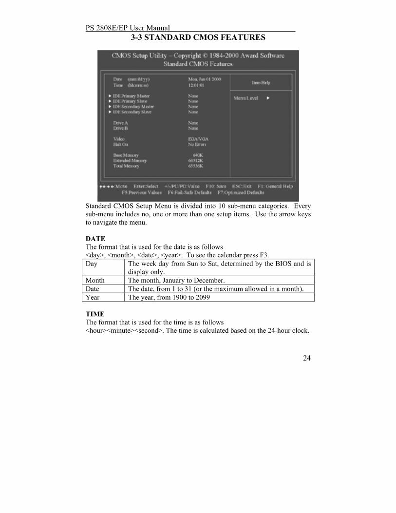
Standard CMOS Setup Menu is divided into 10 sub-menu categories. Every sub-menu includes no, one or more than one setup items. Use the arrow keys to navigate the menu. DATE The format that is used for the date is as follows <day>, <month>, <date>, <year>. To see the calendar press F3. Day The week day from Sun to Sat, determined by the BIOS and is
display only. Month The month, January to December. Date The date, from 1 to 31 (or the maximum allowed in a month). Year The year, from 1900 to 2099 TIME The format that is used for the time is as follows <hour><minute><second>. The time is calculated based on the 24-hour clock.

PS 2808E/EP User Manual
25
PRIMARY MASTER/PRIMARY SLAVE/SECONDARY MASTER/SECONDARY SLAVE These sub-menus are for identifying the 2 channel types that have been installed in the computer. There are 4 user definable and 45 predefined types for the Enchanted IDE BIOS. To select the hard disk you can either press the PageUp or PageDown buttons or simply enter in the number of the hard disk and press <Enter>. It is important the specifications of your selected drive match those of the drive table. The hard disk will not work properly if the incorrect drive information is entered. If you cannot find your drive type on the drive table you may use “User” to define your drive type manually. In order to use “User” type for drive type, you must have certain drive information, the required information is listed below. Enter the information using the keyboard and simply press <Enter>. Either the hard disk vendor or the system manufacturer will most likely have provided this information for you. If the controller of the HDD interface is ESDI, the selection shall be ”Type 1”. If the controller of the HDD interface is SCSI, the selection shall be “None”. If you select Type “Auto”, BIOS will Auto-Detect the HDD & CD-ROM Drive at the POST stage and showing the IDE for HDD & CD-ROM Drive. TYPE drive type CYLS. number of cylinders HEADS number of heads PRECOMP write precom LANDZONE landing zone SECTORS number of sectors MODE mode type If there is no hard drive installed select NONE and press <Enter>. Drive A Type / Drive B Type This sub-menu identifies the types of floppy disk drive A or Drive B that have been installed into the computer. 360K, 5.25 in 5-1/4 inch PC-type standard drive; 360 kilobyte capacity. 1.2M, 5.25 in 5-1/4 inch AT-type high-density drive; 1.2 megabyte
capacity.
PS 2808E/EP User Manual
26
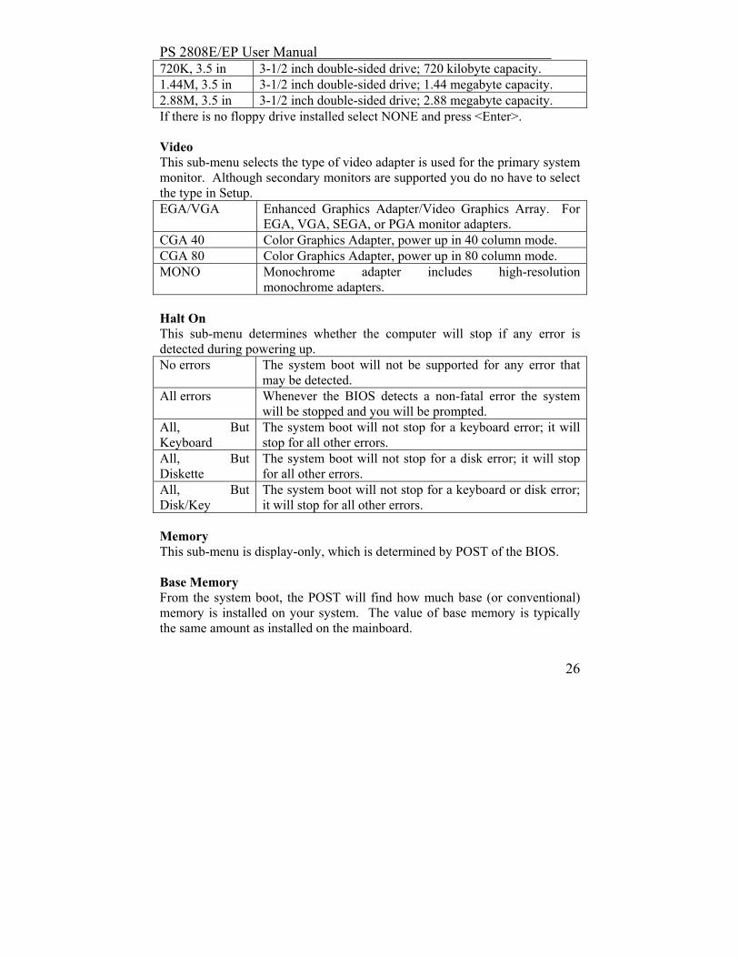
720K, 3.5 in 3-1/2 inch double-sided drive; 720 kilobyte capacity. 1.44M, 3.5 in 3-1/2 inch double-sided drive; 1.44 megabyte capacity. 2.88M, 3.5 in 3-1/2 inch double-sided drive; 2.88 megabyte capacity. If there is no floppy drive installed select NONE and press <Enter>. Video This sub-menu selects the type of video adapter is used for the primary system monitor. Although secondary monitors are supported you do no have to select the type in Setup. EGA/VGA Enhanced Graphics Adapter/Video Graphics Array. For
EGA, VGA, SEGA, or PGA monitor adapters. CGA 40 Color Graphics Adapter, power up in 40 column mode. CGA 80 Color Graphics Adapter, power up in 80 column mode. MONO Monochrome adapter includes high-resolution
monochrome adapters. Halt On This sub-menu determines whether the computer will stop if any error is detected during powering up. No errors The system boot will not be supported for any error that
may be detected. All errors Whenever the BIOS detects a non-fatal error the system
will be stopped and you will be prompted. All, But Keyboard
The system boot will not stop for a keyboard error; it will stop for all other errors.
All, But Diskette
The system boot will not stop for a disk error; it will stop for all other errors.
All, But Disk/Key
The system boot will not stop for a keyboard or disk error; it will stop for all other errors.
Memory This sub-menu is display-only, which is determined by POST of the BIOS. Base Memory From the system boot, the POST will find how much base (or conventional) memory is installed on your system. The value of base memory is typically the same amount as installed on the mainboard.

PS 2808E/EP User Manual
27
Extended Memory During the POST the BIOS will determine how much of extended memory is on the system. This is the amount of memory located above the 1MB in the CPU’s memory address map.
PS 2808E/EP User Manual
28
3-4 ADVANCED BIOS FEATURES
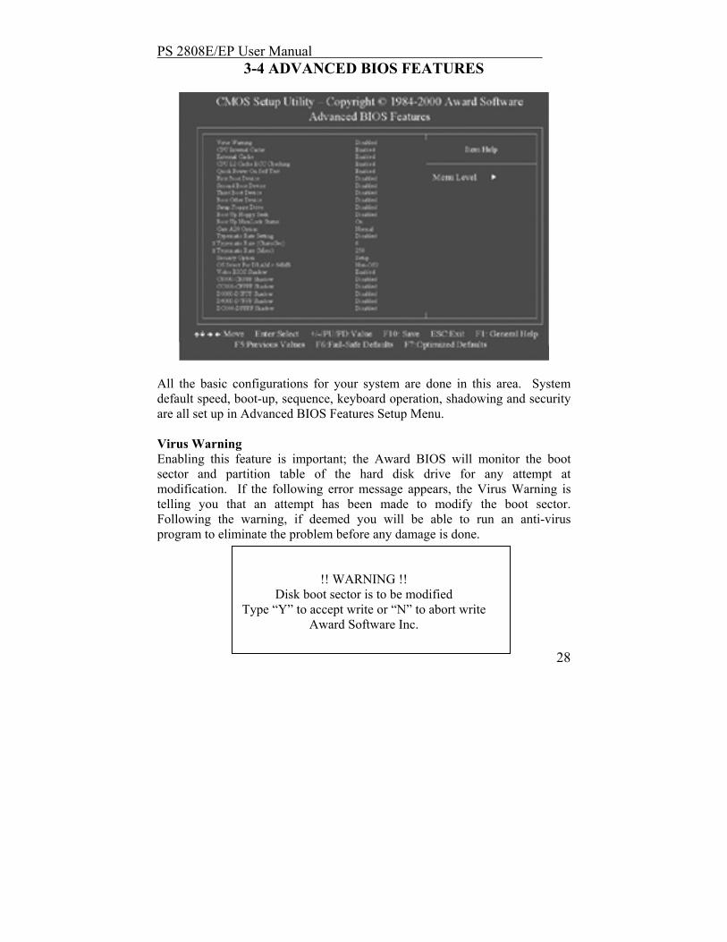
All the basic configurations for your system are done in this area. System default speed, boot-up, sequence, keyboard operation, shadowing and security are all set up in Advanced BIOS Features Setup Menu. Virus Warning Enabling this feature is important; the Award BIOS will monitor the boot sector and partition table of the hard disk drive for any attempt at modification. If the following error message appears, the Virus Warning is telling you that an attempt has been made to modify the boot sector. Following the warning, if deemed you will be able to run an anti-virus program to eliminate the problem before any damage is done.
!! WARNING !! Disk boot sector is to be modified
Type “Y” to accept write or “N” to abort write Award Software Inc.

PS 2808E/EP User Manual
29
Enabled Activates automatically when the system boots up causing
a warning message to appear when anything attempts to access the boot sector or hard disk partition table.
Disabled No warning message will appear when anything attempts to access the boot sector or hard disk partition table.
NOTE: If you are going to be running some sort of a disk diagnostic program we recommend that you disable the warning message. The reason for this is that most of those types of programs need to access the boot sector before running that type of program. CPU Internal Cache/External Cache The following sub-menus speed up memory access. This is something that depends on CPU/chipset design; the default value is enable. Enabled Enable Cache Disabled Disable Cache CPU L2 Cache ECC Checking This item allows you to Enable/Disable CPU L2 Cache EC checking the choices are to either enabled, or disabled. Quick Power On Self-Test This sub-menu speeds up POST after you power up the computer, if it is enabled, BIOS will shorten or skip some check during the POST. Enabled Enable quick POST Disabled Normal POST Boot From LAN First This sub-menu allows the user to choose to Enable/Disable power up the system through a network by sending a wake-up frame or a signal; the choices are to Enabled/Disabled. Boot Sequence (First boot; Second boot; Third boot device) This sub-menu determines which drive to search first for a disk operating system; the default is floppy, HDD-0, LS120.
PS 2808E/EP User Manual
30
Swap Floppy Drive This sub-menu allows you to determine whether to enable the swap floppy drive or not, the choice again is; Enabled, Disabled. Boot Up Floppy Seek BIOS will figure out if the floppy disk drive installed is 40 or 80 tracks. 80 tracks is for 760K, 1.2M , 1.44M, while 360K is a 40 track. Enabled BIOS searches for floppy disk drive to determine if it is 40
or 80 tracks. Note that BIOS cannot tell from 720K, 1.2M or 1.44M drive, as they are all 80 tracks.
Disabled BIOS will not search for the drive type of floppy disk drive by track number. Note that there will not be any warning message if the drive installed is 360K.
Boot Up NumLock Status This will tell you the default state of the numeric keypad, by default the system will boot up with the NumLock on. On Keypad is number keys. Off Keypad is arrow keys. Gate A20 Option This will allow you to select how the GateA20 is handled; it is a device, which is used to address memory above 1 Mbytes. It was first handled via a pin on the keyboard, now it is more common and faster for the system chipset to handle the support GateA20. Normal Keyboard Fast Chipset Memory Parity/ECC Check This item allows you to Enable/Disable Memory Parity/ECC check. Typematic Rate Setting Determines whether or not typematic rate is to be used or not. When disabled, continually holding down a key on your keyboard will tell the BIOS that the key is down. Opposed when enabled it will tell the BIOS the key is down, then it will inform the BIOS the key is being repeatedly being pushed down. Enabled Enabled typematic rate Disabled Disabled typematic rate

PS 2808E/EP User Manual
31
Typematic Rate (Chars/Sec.) This will help to select the rate at which keys are accelerated, when typematic rate is enabled only. 6 6 characters per second 8 8 characters per second 10 10 characters per second 12 12 characters per second 15 15 characters per second 20 20 characters per second 24 24 characters per second 30 30 characters per second Typematic Delay (Msec) When enabled, the typematic rate will allow you to select the delay between when the key was first depressed and when to acceleration should begin. 250 250 msec 500 500 msec 750 750 msec 1000 1000 msec Security Option This category allows you to limit access to the system and Setup, or just to Setup. System The system will not boot and access to Setup will be denied if
the correct password is not entered at the prompt Setup The system will boot, but access to Setup will be denied if the
correct password is not entered at the prompt. Note: To disable the security, select PASSWORD SETTING at Main Menu and then you will be asked to enter password. Don not type anything and just press <Enter>, it will disable security. Once the security is disabled, the system will boot and you can enter Setup freely. OS Select for DRAM>64MB This sub-menu will allow you to access the memory over 64MB in OS/2; the choices will be either, Non-OS/2, or OS2.

PS 2808E/EP User Manual
32
Video BIOS Shadow Will figure out whether video BIOS will be copied to RAM, it is optional depending upon the chipset design. Video Shadow will increase the video speed. Enabled Video shadow is enabled. Disabled Video shadow is disabled. C8000-CBFFF Shadow/DC000-DFFFF Shadow This category will determine whether option ROM’s will be copied. Enabled Optional shadow is enabled. Disabled Optional shadow is disabled.
PS 2808E/EP User Manual
33
3-5 ADVANCED CHIPSET FEATURES
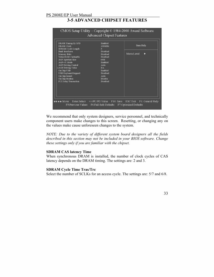
We recommend that only system designers, service personnel, and technically component users make changes to this screen. Resetting, or changing any on the values make cause unforeseen changes to the system. NOTE: Due to the variety of different system board designers all the fields described in this section may not be included in your BIOS software. Change these settings only if you are familiar with the chipset. SDRAM CAS latency Time When synchronous DRAM is installed, the number of clock cycles of CAS latency depends on the DRAM timing. The settings are: 2 and 3. SDRAM Cycle Time Tras/Trc Select the number of SCLKs for an access cycle. The settings are: 5/7 and 6/8.

PS 2808E/EP User Manual
34
SDRAM RAS-to-CAS Delay This field lets you insert a timing delay between the CAS and RAS strobe signals, used when DRAM is written to, read from, or refreshed. Fast gives faster performance; and Slow gives more stable performance. This field applies only when synchronous DRAM is installed in the system. The settings are: 2 and 3. SDRAM RAS Precharge Time If an insufficient number of cycles is allowed for the RAS to accumulate its charge before DRAM refresh, the refresh may be incomplete and the DRAM may fail to retain data. Fast gives faster performance; and Slow gives more stable performance. This field applies only when synchronous DRAM is installed in the system. The settings are: 2 and 3. System BIOS Cacheable Selecting Enabled allows caching of the system BIOS ROM at F0000h-FFFFFh, resulting in better system performance. However, if any program writes to this memory area, a system error may result. The settings are: Enabled and Disabled. Video BIOS Cacheable Select Enabled allows caching of the video BIOS , resulting in better system performance. However, if any program writes to this memory area, a system error may result. The settings are: Enabled and Disabled. CPU Latency Timer During Enabled, A deferrable CPU cycle will only be Deferred after it has been in a Snoop Stall for 31 clocks and another ADS# has arrived. During Disabled, A deferrable CPU cycle will be Deferred immediately after the GMCH receives another ADS#. Delayed Transaction The chipset has an embedded 32-bit posted write buffer to support delay transactions cycles. Select Enabled to support compliance with PCI specification version 2.1. The settings are: Enabled and Disabled. AGP Graphics Aperture Size This option determines the effective size of the graphics aperture used in the particular PAC configuration. The AGP aperture is memory mapped, while
PS 2808E/EP User Manual
35
graphics data structure can reside in a graphics aperture. The aperture range should be programmed as not cacheable in the processor cache, accesses with the aperture range are forwarded to the main memory, then PAC will translate the original issued address via a translation table that is maintained on the main memory. The option allows the selection of an aperture size of 32MB, 64MB. System Memory Frequency Select the Onboard Display Cache frequency. The settings are 100MHz, 133MHz or Auto. Onboard Display Cache Setting (optional) Onboard Display Cache Setting (Optional) CAS# Latency The number of clock cycles of CAS# Latency depends on the Onboard Display cache timing. The settings are: 2 and 3. Paging Mode Control Select the paging mode control. The settings are: Open and Close. RAS-to-CAS Override This item allows you to insert a timing delay between the CAS and RAS strobe signals, used when Onboard display cache is written to, read from, or refreshed. During by CAS# LT, this will depend on the Onboard Display Cache CAS# Latency setting. During Override (2), RAS-to-CAS time= 2. RAS# Timing This option controls RAS# active to Precharge, and refresh to RAS# active delay (in local memory clocks). Slow RAS# to precharge (tRAS) =7, refresh to RAS# act (tRC) = 10 Fast RAS# to precharge (tRAS) =5, refresh to RAS# act (tRC) = 8 RAS# Precharge Timing This item controls RAS# precharge (in local memory clocks) Slow RAS# Precharge Time=3 Fast RAS# Precharge Time=2

PS 2808E/EP User Manual
36
3-6 INTEGRATED PERIPHERALS
OnChip Primary/Secondary PCI IDE The integrated peripheral controller contains an IDE interface with support for two IDE channels. Select Enabled to activate each channel separately. The settings are: Enabled and Disabled. IDE Prefetch Mode IDE prefetching is used to access the IDE hard drive faster. You will need to disable this mode if there is an add-in IDE card that does not support prefetching. IDE Primary/Secondary Master/Slave PIO PIO (Input/Output) is the mode for which your hard drive supports. Newer IDE devices are usually Mode 3 or 4. When set to AUTO, the system will determine the most efficient mode.

PS 2808E/EP User Manual
37
IDE Primary/Secondary Master/Slave UDMA This option may be enabled only if your IDE device supports DMA 33 and you are running Windows 95 OSR2 or higher or a third-party IDE bus master driver. USB Controller Select Enabled if your system contains a Universal Serial Bus (USB) controller and you have USB peripherals. The settings are: Enabled, Disabled. USB Keyboard Support Select Enabled if your system contains a Universal Serial Bus (USB) controller and you have a USB keyboard. The settings are: Enabled, Disabled. Init Display First Here you have to tell the system what type of video card interface you are using. Choose PCI/AGP if you choose to use a PCI based graphics card or AGP/PCI if you have an AGP based graphics card. AC97 Audio/Modem This item allows you to decide to enable/disable the 815 chipset family to support AC97 Audio and Modem. IDE HDD Block Mode Most newer IDE drives support block transferring for faster access. If you choose “Enable” then the system will automatically detect the optimal block read/writes per sector. Power On Function This function allows you to select the item to power on the system. The settings are : Button Only, Mouse Left, Mouse Right, Password, Hotkey, keyboard 98. Onboard FDD Controller Select Enabled if your system has a floppy disk controller (FDD) installed on the system board and you wish to use it. If you install add-on FDC or the system has no floppy drive, select Disabled in this field. The settings are: Enabled and Disabled.

PS 2808E/EP User Manual
38
Onboard Serial Port 1/Port 2 Select an address and corresponding interrupt for the first and second serial ports. The settings are: 3F8/IRQ4, 2E8/IRQ3, 3E8/IRQ4, 2F8/IRQ3, Disabled, Auto. UART 2 Mode This gives you the options to set your on-board IR (infra-red) port chip. The choices are standard, ASKIR, HPSIR IR Function Duplex Here you can set the IR port function to either full duplex or half duplex. TX, RX Inverting enable Depending on different hardware requirements, this is used to invert the transmit/receive settings. To avoid system errors, it is recommended that you do not change the default settings. Onboard Parallel Port Here you can change the on-board parallel port address. 378H/IRQ7: LPT1 278H/IRQ5: LPT2 3BCH/IRQ7: LPT3 or you can choose disable the on-board port. Onboard Parallel Port Mode The parallel port mode is determined by the external parallel devices. EPP (Extended Parallel Port) ECP (Extended Capabilities Port) ECP/EPP SPP (Standard Parallel Port) ECP Mode Use DMA Choose a DMA (Direct Memory Access) channel for the port. Parallel Port EPP Type Choose version 1.7 or 1.9 for EPP mode.

PS 2808E/EP User Manual
39
3-7 POWER MANAGEMENT SETUP The Power Management Setup allows the user to manually configure your system to achieve the highest level of energy saving desired.
ACPI Function This item allows you to Enabled/Disabled the Advanced Configuration and Power Management (ACPI). The settings are Enabled and Disabled. ACPI Suspend Type This item will set which ACPI suspend type will be used. S1 (POS): the S1 sleeping state is low wake-up latency sleeping state. In this state, no system context is lost (CPU or chip set) and hardware maintains all system context. S3 (STR): the S3 state is a low wake-up latency sleeping sate where all system context is lost expect system memory. CPU, cache, and chipset context are lost in this state. Hardware maintains memory context and restores some CPU and L2 configuration context.
PS 2808E/EP User Manual
40
Power Management This option allows the user to select the desired level of power saving. The Power Management menu will offer the user three choices directly related to the following modes: Suspend Mode HDD Power Down Mode There are three selections for Power Management, two of which have fixed mode settings: Min. Power Saving Lowest level of active power saving Suspend mode = 1hr Standby mode = 1hr HDD Power Down = 15min Max. Power Saving Highest level of active power saving Suspend mode = 1min Standby mode = 1min HDD Power Down = 1min User Defined Allows you to set each mode individually. When not disabled, each of the ranges are from 1 min. to 1 hr. except for HDD Power Down which ranges from 1 min. to 15 min. and disable The user will also have the option to disable (default) the Power Management option. Video Off Method This option determines in what way the monitor will be shut down V/H SYNC + Blank This option will cause the system to turn off the vertical and horizontal synchronization ports and write blanks to the video buffer. Blank Screen This option will only write blanks to the video buffer. DPMS Support Initial display power management signaling.
PS 2808E/EP User Manual
41
Video Off Option This option allows the user to select the Power Saving mode which shuts down the monitor during periods of extended inactivity. Suspend Type Select the Suspend Type. The settings are: PWRON Suspend, Stop Grant. Modem Use IRQ This option determines the IRQ which the modem will use. Suspend Mode When enabled and after the set time of system inactivity, all devices except the CPU will be shut off. The settings are: 1/2/4/8/12/20/30/40 Min, 1 Hour, and Disabled. HDD Power Down When selected, this option will power down the Hard Drive after a given time. The user may choose 1-15 minute time frames. Soft-Off by PWRBTN When enabled, this option allows the user to place the system in a very-low power usage state simply by using the ON/OFF power button. By pressing the OFF button the system will receive only enough power to detect power button activity as well as Resume by Ring activity. The Soft-Off by PWRBTN allows you to select two options Instant Off and Delay 4 Sec. Wake-Up by PCI Card This will enable the system to wake up through PCI Card peripheral. The settings are: Enabled and Disabled. Power On by Ring During Disabled, the system will ignore any incoming call from the modem. During Enabled, the system will boot up if there’s an incoming call from the modem. Wake-Up on LAN To use this function, you need a LAN add-on card which support power on functions. It should also support the wake-up on LAN jumper (JWOL1).
Enabled Wake up on LAN supported.

PS 2808E/EP User Manual
42
Disabled Wake up on LAN not supported. USB KB Wake-Up From S3 This option is used to Enabled/Disabled USB keyboard wake up with suspend to RAM. Resume by Alarm This function is for setting date and time for your computer to boot up. During Disabled, you cannot use this function. During Enabled, choose the Date and Time Alarm:
Date (of month) Alarm You can choose which month the system will boot up. Set to 0, to boot every day.
Time (hh:mm:ss) Alarm You can choose what hour, minute and second the system will boot up.
Note: If you have change the setting, you must let the system boot up until it goes to the operating system, before this function will work.
Reload Global Timer Events Reload Global Timer events are I/O events whose occurrence can prevent the system from entering a power saving mode or can awaken the system from such a mode. In effect, the system remains alert for anything which occurs to a device which is configured as Enabled, even when the system is in a power down mode.
Primary IDE 0 Primary IDE 1 Secondary IDE 0 Secondary IDE 1 FDD, COM, LPT Port PCI PIRQ[A-D] #

PS 2808E/EP User Manual
43
3-8 PNP/PCI Configuration
This section outlines the procedures for configuring the PCI (Personal Computer Interconnect) bus system. The PCI bus system allow I/O devices to operate at speeds nearing the speed the CPU itself uses when communicating with its own special components. It is recommended that only experienced users make any changes to the default settings, as the items covered in this section are very technical. PNP OS Installed Select Yes if the system operating environment is Plug-and Play aware. The Choice: Yes, No. Resource Controlled by The Award Plug and Play BIOS can automatically configure all the boot and Plus and Play - compatible devices. If you select Auto, all the interrupt requests (IRQ) and DMA assignment fields disappear, as the BIOS automatically assigns them. The Choice: Auto, Manual

PS 2808E/EP User Manual
44
Reset Configuration Data Normally, you lave this field Disabled. Select Enabled to reset Extended System Configuration Data (ESCD) when you exit Setup if you have installed a new add-on and the system configuration has caused such as serious conflict that the operating system cannot boot. The Choice: Enabled, Disabled IRQ Resources When resources are controlled manually, assign each system interrupt as one of the following types, depending on the type of device using the interrupt: Legacy ISA Devices compliant with the original PC AT bus specification, requiring a specific interrupt (such as IRQ4 for serial port 1). The Choice: Enabled, Disabled DMA Resources When resources are controlled manually, assign each system DMA channel as one of the following types, depending on the type of device using the interrupt: Legacy ISA Devices compliant with the original PC AT bus specification, requiring a specific DMA channel PCI/ISA PnP Devices compliant with the Plug and Play standard, whether designed for PCI or ISA bus architecture. PCI/VGA Palette Snoop Leave this field at Disabled. The settings are Enabled, Disabled.

PS 2808E/EP User Manual
45
3-9 DEFAULTS MENU After selecting “Defaults” from the main menu, there will be two options. LOAD FAIL-SAFE DEFAULTS This will load the most stable default bios settings. These settings will give you minimal system performance. This setting is mainly used for troubleshooting errors. LOAD OPTIMIZED DEFAULTS This will load the optimal factory default settings.

PS 2808E/EP User Manual
46
3-10 PC HEALTH STATUS The mainboard contains sensors, which read the systems temperature settings and fan rotation speeds.
Shutdown Temperature This option is for setting the Shutdown temperature level for the processor. When the processor reach the temperature you set, this will shutdown the system. Current CPU Core, Vcc 1.8V, Vcc 3.3V, Vcc 5V, +12V, -12V, -5V, 5VSB, Battery, CPU Temperature, Fan 1 Speed, Fan 2 Speed This will show the CPU/FAN/System voltage info and fan speed.

PS 2808E/EP User Manual
47
3-11 FREQUENCY/VOLTAGE CONTROL
Auto Detect DIMM/PCI Clock Used to Enable/Disable the system auto detect DIMM/PCI clock. Spread Spectrum Modulated Used to Enable/Disable the Clock Spread Spectrum. CPU Host/PCI Clock Here you have the option to change the CPU and PCI frequencies. It will allow you to control fan rotations, voltages, and temperatures. CPU Clock Ratio This option is used to set the CPU multiplier. Note: We do not guarantee that the mainboard or other components will work properly after overclocking.

PS 2808E/EP User Manual
48
3-12 PASSWORD SETTING For added security, your system has BIOS password options to prohibit unwanted individuals from making harmful changes to your BIOS. Supervisor password: Gives full access to view and make changes. User password: Allows viewing of bios setting but changes cannot be made. If you wish to disable either of the above choices then you can hit <enter> either on supervisor or user password. The password option may also be used to keep unwanted parties from using the system. If you choose “system” in the Security option under the BIOS features Setup Menu, a password will be required to start up the system. If you choose “setup” then a password will only be required to enter the bios setup.
3-13 EXIT SELECTING SAVE & EXIT SETUP To save all CMOS selections to memory and restart the system, choose (Y)es. EXIT WITHOUT SAVING To exit the CMOS setup and restarting the system without saving any changes made.