pryda timber connectors · design capacities- wind uplift . ... exposed base plate and stem with...
TRANSCRIPT
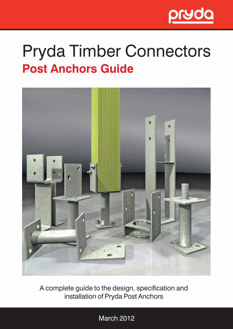
Pryda Timber ConnectorsPost Anchors Guide
A complete guide to the design, specification andinstallation of Pryda Post Anchors
March 2012


ESSENTIAL NOTES – PRYDA PRODUCT GUIDES
Copyright: © Pryda Australia - A Division of ITW Australia – ABN 63 004 235 063 - 2012
INTRODUCTION The information in this Product Guide is provided for use in Australia by architects, engineers, building designers, builders and others. It is based upon the following criteria: 1. No Substitution: The products covered by or recommended in
this guide must not be substituted with other products. 2. Design Capacity Basis: See Codes & Standards following 3. Supporting Constructions: Constructions using Pryda
products must be built in accordance with the BCA or an appropriate Australian standard. Note: This includes appropriate corrosion protection- See Corrosion Protection following
4. Correct Installation: Installation of Pryda products must be
strictly in accordance with the instructions in this guide 5. Current Guide Version Used: The current version of this
guide, including any amendments or additions, must be used. Users are advised to check with Pryda for updates at least every three months by telephone, the web site: www.pryda.com.au or by email to: [email protected].
CODES & STANDARDS Product design capacities in this guide have been derived from: (a) results of laboratory tests carried out by or for Pryda Australia (b) engineering computations in accordance with the relevant
Australian standards, ie: * AS1720.1-2010 Timber Structures. Part 1: Design Methods * AS/NZS1170 series : 2002 Structural Design Actions * AS4055 -2006 Wind Loads for Housing Reference is also made to AS1684.1-1999 Residential Timber Framed Construction - Part 1: Design Criteria.
Design capacities tabulated in this guide apply directly for Category 1 joints. For all other joints, reduce design capacities by using the factors as specified in General Notes (if applicable). Design capacities are related to the Joint Group of the timber as defined in AS1720 and AS1684. If the joint group of timber members joined together varies, the lower group must be assumed for design, eg: JD5 is lower than JD4. DEFINITIONS Special terms used in this guide are as defined in Australian standards, including: Design Capacity: the maximum Limit State Design load (aka “action”) which the product can safely support under the specified load condition, eg: 1.2G + 1.5Q (dead+roof live). See General Notes for details (if applicable) Joint Group: classification of a timber according to its fastener-holding capacity. See General Notes for details (if applicable)
CORROSION PROTECTION Most Pryda products are manufactured using Z275 light-gauge steel, having zinc coating of 275 gsm (total weight). This protection is adequate only for INTERNAL applications in most corrosion environments, except areas that are classified as heavy industrial or those subject to high humidity (eg: enclosed swimming pools) etc. Under these circumstances, seek advice from experts as special protection will be required. Note: INTERNAL areas are those within the building envelope that are kept permanently dry. AS1684.2-2010 and AS1684.3-2010- Australian Standards for Residential Timber Frame Construction stipulates a minimum Z275 steel for all sheet metal products used in an internal environment. In areas outside the building envelope that are exposed to repeated wetting (EXTERNAL areas), Pryda’s stainless steel products or equivalent should be considered. Some alternatives include hot dip galvanised or powder coated steel, which are not supplied by Pryda. For more detailed information, read Pryda’s Technical Update on Corrosion Resistance of Pryda Products or contact a Pryda office. PRODUCT CERTIFICATION Pryda Australia warrants: * Products in this guide are free from defects in the material or
manufacturing * Design capacities are in accordance with test results or current,
relevant Australian standards and the Building Code of Australia.
* Pryda products are structurally adequate provided they are designed, installed and used completely in accordance with this guide.
This warranty applies only to: * products in this guide * products used in the specified applications and not damaged
after manufacture and supply * joints free from wood splitting, decay or other timber defects
within the joint or within 150 mm of the joint. INSTRUCTIONS FOR INSTALLATION These notes are provided to ensure proper installation. 1. All fasteners used must be manufactured by reputable
companies and be of structural quality. 2. Connectors must not be installed on timber which is split before
or during installation. If the timber is likely to split as fasteners are driven, fastener holes must be pre-drilled.
3. Do not overload the joints- during construction or in service. 4. Bolt hole diameter must be 0.8 mm to 1.5 mm larger than the
bolt diameter and the specified washers must be installed. 5. Use proper safety equipment and due care in installing these
connectors 6. Any gaps in joints between the timber members must not
exceed 3 mm 7. Do not over-tighten screws.
POST ANCHORS GUIDE – MARCH 2012 3
Pryda Post Anchors Guide
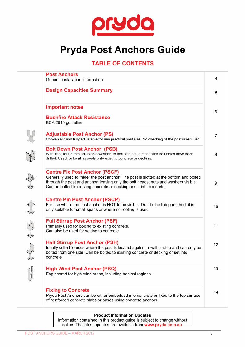
TABLE OF CONTENTS
Post Anchors General installation information Design Capacities Summary Important notes Bushfire Attack Resistance BCA 2010 guideline Adjustable Post Anchor (PS) Convenient and fully adjustable for any practical post size. No checking of the post is required Bolt Down Post Anchor (PSB) With knockout 3 mm adjustable washer- to facilitate adjustment after bolt holes have been drilled. Used for locating posts onto existing concrete or decking.
Centre Fix Post Anchor (PSCF) Generally used to “hide” the post anchor. The post is slotted at the bottom and bolted through the post and anchor, leaving only the bolt heads, nuts and washers visible. Can be bolted to existing concrete or decking or set into concrete Centre Pin Post Anchor (PSCP) For use where the post anchor is NOT to be visible. Due to the fixing method, it is only suitable for small spans or where no roofing is used Full Stirrup Post Anchor (PSF) Primarily used for bolting to existing concrete. Can also be used for setting to concrete Half Stirrup Post Anchor (PSH) Ideally suited to uses where the post is located against a wall or step and can only be bolted from one side. Can be bolted to existing concrete or decking or set into concrete High Wind Post Anchor (PSQ) Engineered for high wind areas, including tropical regions. Fixing to Concrete Pryda Post Anchors can be either embedded into concrete or fixed to the top surface of reinforced concrete slabs or bases using concrete anchors
4 5
6 7
8
9
10
11
12
13
14
Product Information Updates
Information contained in this product guide is subject to change without notice. The latest updates are available from www.pryda.com.au.
PRYDA TIMBER CONNECTORS Post Anchors Guide
POST ANCHORS GUIDE – MARCH 2012 4
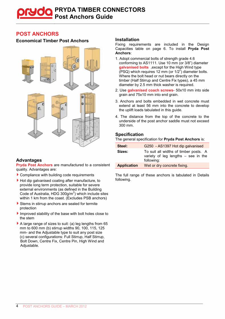
POST ANCHORS Economical Timber Post Anchors
Advantages Pryda Post Anchors are manufactured to a consistent quality. Advantages are:
Compliance with building code requirements Hot dip galvanised coating after manufacture, to provide long term protection, suitable for severe external environments (as defined in the Building Code of Australia, HDG 300g/m2) which include sites within 1 km from the coast. (Excludes PSB anchors) Stems in stirrup anchors are sealed for termite protection Improved stability of the base with bolt holes close to the stem A large range of sizes to suit: (a) leg lengths from 65 mm to 600 mm (b) stirrup widths 90, 100, 115, 125 mm- and the Adjustable type to suit any post size (c) several configurations: Full Stirrup, Half Stirrup,
Installation Fixing requirements are included in the Design Capacities table on page 6. To install Pryda Post Anchors: 1. Adopt commercial bolts of strength grade 4.6
conforming to AS1111. Use 10 mm (or 3/8”) diameter galvanised bolts ,except for the High Wind type (PSQ) which requires 12 mm (or 1/2”) diameter bolts. Where the bolt head or nut bears directly on the timber (Half Stirrup and Centre Fix types), a 45 mm diameter by 2.5 mm thick washer is required.
2. Use galvanised coach screws- 50x10 mm into side grain and 75x10 mm into end grain.
3. Anchors and bolts embedded in wet concrete must extend at least 56 mm into the concrete to develop the uplift loads tabulated in this guide.
4. The distance from the top of the concrete to the underside of the post anchor saddle must not exceed 300 mm.
Specification The general specification for Pryda Post Anchors is:
Steel: G250 - AS1397 Hot dip galvanised Sizes: To suit all widths of timber posts. A
variety of leg lengths – see in the following:
Application Wet or dry concrete fixing. The full range of these anchors is tabulated in Details following.
Bolt Down, Centre Fix, Centre Pin, High Wind and Adjustable.

PRYDA TIMBER CONNECTORS Post Anchors Guide
POST ANCHORS GUIDE – MARCH 2012 5
Design Capacities- Wind Uplift Limit State Design capacities (ΦNj) for Pryda Standard Post Anchors resisting wind uplift loads are as follows:
Post Anchor Post (mm)
Uplift Capacities for varying joint groups
Fixing J4 J3 J2 JD5 JD4 JD3 JD2
Adjustable PS
4@ 50x10 mm coach
screws
90 min.
4.6 7.4 9.2 5.8 8.4 11.9 12
Bolt Down PSB
2@ M10 bolts Any
Refer to Page 8
Centre Fix PSCF
2@ M10 bolts 90 9.1 11.5 12.0 11.5 12.0 12.0 12.0
Centre Pin PSCP
2@ 75x10 mm coach
screws Any 4.1 6.0 8.2 3.9 5.2 7.5 10.3
Full Stirrup
PSFS
2@ M10 bolts 12.0 12.0 12.0 12.0 12.0 12.0 12.0
4@ 50x10 mm
coach screws
90 6.3 10.1 12.0 6.7 10.6 12.0 12.0 100 6.1 9.6 12.0 6.5 10.3 12.0 12.0 115 5.7 9.0 12.0 6.1 9.8 12.0 12.0 125 5.3 8.5 11.7 5.9 9.3 12.0 12.0
Half Stirrup
PSHS
2@ M10 bolts
Any
5.3 5.3 5.3 5.3 5.3 5.3 5.3
2@ 50x10 mm coach
screws 5.3 5.3 5.3 5.3 5.3 5.3 5.3
High Wind PSQ
2@ M12 bolts Any 33 41 45 36 41 50
*Refer to notes on next page
PRYDA TIMBER CONNECTORS Post Anchors Guide
POST ANCHORS GUIDE – MARCH 2012 6
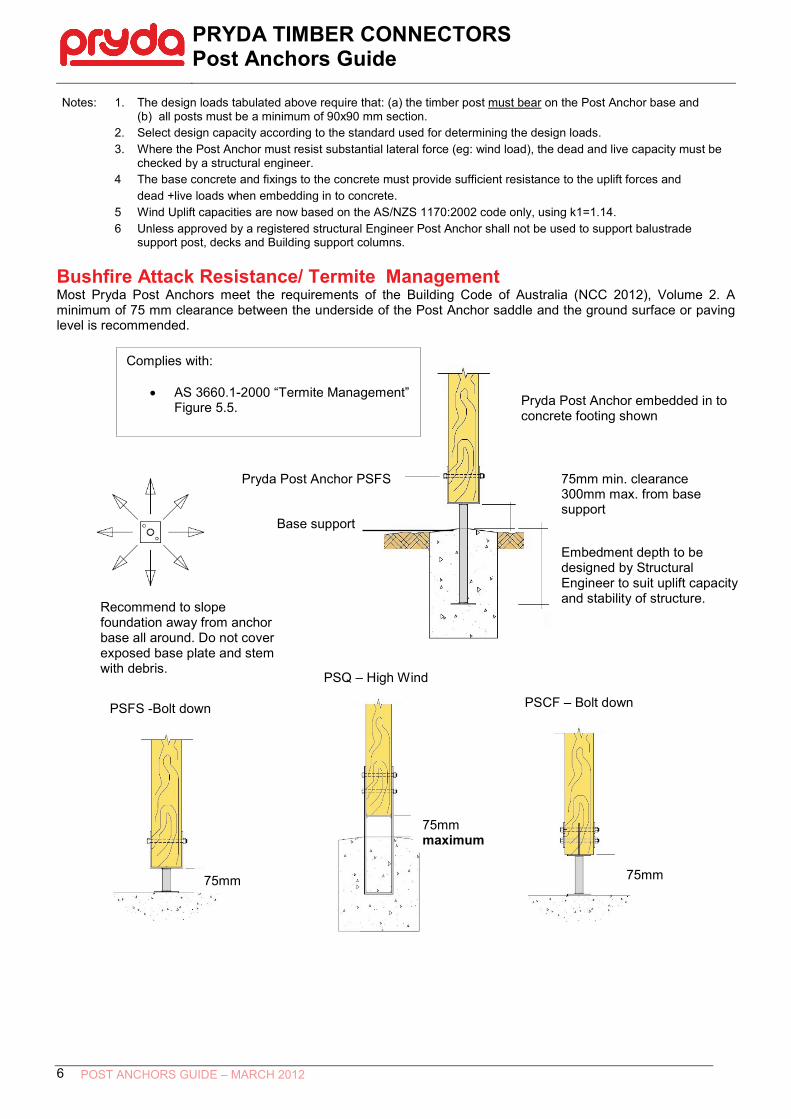
Notes: 1. The design loads tabulated above require that: (a) the timber post must bear on the Post Anchor base and (b) all posts must be a minimum of 90x90 mm section.
2. Select design capacity according to the standard used for determining the design loads. 3. Where the Post Anchor must resist substantial lateral force (eg: wind load), the dead and live capacity must be
checked by a structural engineer. 4 The base concrete and fixings to the concrete must provide sufficient resistance to the uplift forces and
dead +live loads when embedding in to concrete. 5 Wind Uplift capacities are now based on the AS/NZS 1170:2002 code only, using k1=1.14. 6 Unless approved by a registered structural Engineer Post Anchor shall not be used to support balustrade
support post, decks and Building support columns.
Bushfire Attack Resistance/ Termite Management Most Pryda Post Anchors meet the requirements of the Building Code of Australia (NCC 2012), Volume 2. A minimum of 75 mm clearance between the underside of the Post Anchor saddle and the ground surface or paving level is recommended.
Pryda Post Anchor embedded in to concrete footing shown
75mm min. clearance 300mm max. from base support
Complies with:
• AS 3660.1-2000 “Termite Management” Figure 5.5.
Pryda Post Anchor PSFS
75mm maximum
75mm 75mm
PSFS -Bolt down
PSQ – High Wind
PSCF – Bolt down
Embedment depth to be designed by Structural Engineer to suit uplift capacity and stability of structure.
Base support
Recommend to slope foundation away from anchor base all around. Do not cover exposed base plate and stem with debris.

PRYDA TIMBER CONNECTORS Post Anchors Guide
POST ANCHORS GUIDE – MARCH 2012 7
Adjustable Post Anchor Convenient and fully adjustable for any practical post size. No checking of the post is required Details Pryda Post Anchors conform to AS3660.1 – 2000, Protection of Buildings from Termites. All joints are welded. Steel G250 AS1397 -2001 Adjustable Post Anchors - Hot Dipped Galvanised 4 mm Steel Product Code
Article & Size
Packed
Packed
PS85 85 Leg Length 10 10 PS160 160 Leg Length 10 10 PS200 200 Leg Length 10 10 Adjustable Post Anchor Design Capacities- Steel Strength only Ultimate Limit State Design capacities (ΦNc, ΦNt) for Pryda Standard Post
Product Code
Axial Compression ΦNc (kN)
Axial Tension ΦNt (kN)
PS85 25 12 PS160 16
PS200 20
Design Capacities- Wind Uplift Limit State Design capacities (ΦNj) for Pryda Standard Post Anchors resisting wind uplift loads are as follows: Post Anchor
Post (mm)
Uplift Capacities for varying joint groups
Fixing J4 J3 J2 JD5 JD4 JD3 JD2
Adjustable PS 4@ 50x10 mm coach screws
90 min. 4.6 7.4 9.2 5.8 8.4 11.9 12
Notes:
1.
The design loads tabulated above require that: (a) the timber post must bear on the Post Anchor base and (b) all posts must be a minimum of 90x90 mm section.
2 The base concrete and fixings to the concrete must provide sufficient resistance to the uplift forces. 3 Where the Post Anchor must resist substantial lateral force (eg: wind load), the combined dead /live and lateral
wind loads must be checked by a structural engineer for suitability with selected post anchor. 4
5 AS/NZS 1170:2002 code, using k1=1.14 Unless approved by a registered structural Engineer Post Anchor shall not be used to support balustrade post, decks and stumps.
PRYDA TIMBER CONNECTORS Post Anchors Guide
POST ANCHORS GUIDE – MARCH 2012 8
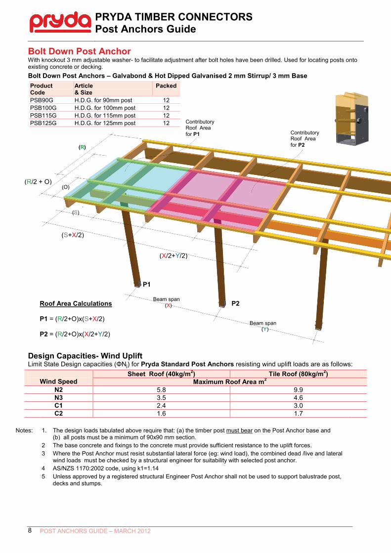
Bolt Down Post Anchor With knockout 3 mm adjustable washer- to facilitate adjustment after bolt holes have been drilled. Used for locating posts onto existing concrete or decking. Bolt Down Post Anchors – Galvabond & Hot Dipped Galvanised 2 mm Stirrup/ 3 mm Base Product Code
Article & Size
Packed
PSB90G H.D.G. for 90mm post 12 PSB100G H.D.G. for 100mm post 12 PSB115G H.D.G. for 115mm post 12 PSB125G H.D.G. for 125mm post 12
Design Capacities- Wind Uplift Limit State Design capacities (ΦNj) for Pryda Standard Post Anchors resisting wind uplift loads are as follows:
Wind Speed
Sheet Roof (40kg/m2) Tile Roof (80kg/m2) Maximum Roof Area m2
N2 5.8 9.9 N3 3.5 4.6 C1 2.4 3.0 C2 1.6 1.7
Notes:
1.
The design loads tabulated above require that: (a) the timber post must bear on the Post Anchor base and (b) all posts must be a minimum of 90x90 mm section.
2 The base concrete and fixings to the concrete must provide sufficient resistance to the uplift forces. 3 Where the Post Anchor must resist substantial lateral force (eg: wind load), the combined dead /live and lateral
wind loads must be checked by a structural engineer for suitability with selected post anchor. 4
5 AS/NZS 1170:2002 code, using k1=1.14 Unless approved by a registered structural Engineer Post Anchor shall not be used to support balustrade post, decks and stumps.
P2
(R)
Contributory Roof Area for P1
Beam span (X)
Contributory Roof Area for P2
P1
Beam span (Y)
(S)
(O)
(R/2 + O)
P1 = (R/2+O)x(S+X/2)
P2 = (R/2+O)x(X/2+Y/2)
Roof Area Calculations
(S+X/2)
(X/2+Y/2)

PRYDA TIMBER CONNECTORS Post Anchors Guide
POST ANCHORS GUIDE – MARCH 2012 9
Centre Fix Post Anchor Generally used to “hide” the post anchor. The post is slotted at the bottom and bolted through the post and anchor, leaving only the bolt heads, nuts and washers visible. Can be bolted to existing concrete or set into concrete. Details Pryda Post Anchors conform to AS3660.1 – 2000, Protection of Buildings from Termites. All joints are welded. Range dimensions are: Stem– 25 mm diameter x 2.0 mm thickness, Stirrup thickness = 4 mm. Steel G250 AS1397 -2001 Centre Fix Post Anchors - Hot Dipped Galvanised 4 mm Steel Product Code
Article & Size
Packed
PSCF130 130 Leg Length 10 PSCF300 300 Leg Length 10 Centre Fix Post Anchor Design Capacities- Wind Uplift Limit State Design capacities (ΦNj) for Pryda Standard Post Anchors resisting wind uplift loads are as follows: Post Anchor
Post (mm)
Uplift Capacities for varying joint groups
Fixing J4 J3 J2 JD5 JD4 JD3 JD2
Centre Fix PSCF 2@ M10 bolts 90 9.1 11.5 12.0 11.5 12.0 12.0 12.0 Notes:
1.
The design loads tabulated above require that: (a) the timber post must bear on the Post Anchor base and (b) all posts must be a minimum of 90x90 mm section.
2. Design dead and live loads are likely to be limited by the capacity of the post, but should not exceed 16 kN at the maximum stem height of 300 mm and 25kN for 130mm stem height or less.
3 The base concrete and fixings to the concrete must provide sufficient resistance to the uplift forces and dead +live loads when setting to concrete.
4 AS/NZS 1170:2002 code, using k1=1.14 5 Unless approved by a registered structural Engineer Post Anchor shall not be used to support balustrade post,
decks and stumps..
7575
130/300
75100
PRYDA TIMBER CONNECTORS Post Anchors Guide
POST ANCHORS GUIDE – MARCH 2012 10
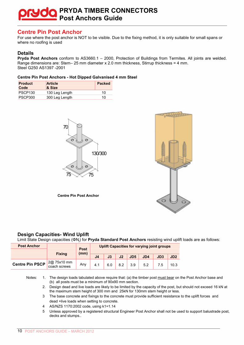
Centre Pin Post Anchor For use where the post anchor is NOT to be visible. Due to the fixing method, it is only suitable for small spans or where no roofing is used Details Pryda Post Anchors conform to AS3660.1 – 2000, Protection of Buildings from Termites. All joints are welded. Range dimensions are: Stem– 25 mm diameter x 2.0 mm thickness, Stirrup thickness = 4 mm. Steel G250 AS1397 -2001 Centre Pin Post Anchors - Hot Dipped Galvanised 4 mm Steel Product Code
Article & Size
Packed
PSCP130 130 Leg Length 10 PSCP300 300 Leg Length 10 Centre Pin Post Anchor Design Capacities- Wind Uplift Limit State Design capacities (ΦNj) for Pryda Standard Post Anchors resisting wind uplift loads are as follows: Post Anchor
Post (mm)
Uplift Capacities for varying joint groups
Fixing J4 J3 J2 JD5 JD4 JD3 JD2
Centre Pin PSCP 2@ 75x10 mm coach screws Any 4.1 6.0 8.2 3.9 5.2 7.5 10.3
Notes:
1.
The design loads tabulated above require that: (a) the timber post must bear on the Post Anchor base and (b) all posts must be a minimum of 90x90 mm section.
2. Design dead and live loads are likely to be limited by the capacity of the post, but should not exceed 16 kN at the maximum stem height of 300 mm and 25kN for 130mm stem height or less.
3 The base concrete and fixings to the concrete must provide sufficient resistance to the uplift forces and dead +live loads when setting to concrete.
4 AS/NZS 1170:2002 code, using k1=1.14 5 Unless approved by a registered structural Engineer Post Anchor shall not be used to support balustrade post,
decks and stumps..
7575
130/300
70
PRYDA TIMBER CONNECTORS Post Anchors Guide
POST ANCHORS GUIDE – MARCH 2012 11
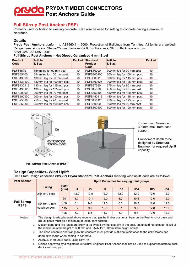
Full Stirrup Post Anchor (PSF) Primarily used for bolting to existing concrete. Can also be used for setting to concrete having a maximum clearance. Details Pryda Post Anchors conform to AS3660.1 – 2000, Protection of Buildings from Termites. All joints are welded. Range dimensions are: Stem– 25 mm diameter x 2.0 mm thickness, Stirrup thickness = 4 mm. Steel G250 AS1397 -2001 Full Stirrup Post Anchors – Hot Dipped Galvanised 4 mm Steel
Product Code
Article & Size
Packed
Standard Product Code
Article & Size
Packed
PSFS6590 65mm leg for 90 mm post 10 PSFS30090 300mm leg for 90 mm post 10 PSFS65100 65mm leg for 100 mm post 10 PSFS300100 300mm leg for 100 mm post 10 PSFS13090 130mm leg for 90 mm post 10 PSFS300115 300mm leg for 115 mm post 10 PSFS130100 130mm leg for 100 mm post 10 PSFS300125 300mm leg for 125 mm post 10 PSFS130115 130mm leg for 115 mm post 10 PSFS37590 375mm leg for 90 mm post 10 PSFS130125 130mm leg for 125 mm post 10 PSFS45090 450mm leg for 90 mm post 10 PSFS20090 200mm leg for 90 mm post 10 PSFS450100 450mm leg for 100 mm post 10 PSFS200100 200mm leg for 100 mm post 10 PSFS450115 450mm leg for 115 mm post 10 PSFS25090 250mm leg for 90 mm post 10 PSFS450125 450mm leg for 125 mm post 10 PSFS250100 250mm leg for 100 mm post 10 PSFS60090 600mm leg for 90 mm post 10 PSFS600100 600mm leg for 100 mm post 10 Full Stirrup Post Anchor (PSF) Design Capacities- Wind Uplift Limit State Design capacities (ΦNj) for Pryda Standard Post Anchors resisting wind uplift loads are as follows: Post Anchor
Post (mm)
Uplift Capacities for varying joint groups
Fixing J4 J3 J2 JD5 JD4 JD3 JD2
Full Stirrup PSFS
2@ M10 bolts 12.0 12.0 12.0 12.0 12.0 12.0 12.0
4@ 50x10 mm coach screws
90 6.3 10.1 12.0 6.7 10.6 12.0 12.0 100 6.1 9.6 12.0 6.5 10.3 12.0 12.0 115 5.7 9.0 12.0 6.1 9.8 12.0 12.0 125 5.3 8.5 11.7 5.9 9.3 12.0 12.0
Notes: 1. The design loads tabulated above require that: (a) the timber post must bear on the Post Anchor base and (b) all posts must be a minimum of 90x90 mm section.
2. Design dead and live loads are likely to be limited by the capacity of the post, but should not exceed 16 kN at the maximum stem height of 300 mm and 25kN for 130mm stem height or less.
3 The base concrete and fixings to the concrete must provide sufficient resistance to the uplift forces and dead +live loads when setting to concrete.
4 AS/NZS 1170:2002 code, using k1=1.14 5 Unless approved by a registered structural Engineer Post Anchor shall not be used to support balustrade post,
decks and stumps.
7575
65/130/200/250300/375/450/600
109
7592/102/117/127
Embedment depth to be designed by Structural Engineer for required Uplift capacity
75mm min. Clearance 300mm max. from base support

PRYDA TIMBER CONNECTORS Post Anchors Guide
POST ANCHORS GUIDE – MARCH 2012 12
Half Stirrup Post Anchor (PSH) Ideally suited to uses where the post is located against a wall or step and can only be bolted from one side. Can be bolted to existing concrete or decking or set into concrete. Details Pryda Post Anchors conform to AS3660.1 – 2000, Protection of Buildings from Termites. All joints are welded. Range dimensions are: Stem– 25 mm diameter x 2.0 mm thickness, Stirrup thickness = 4 mm. Steel G250 AS1397 -2001 Half Stirrup Post Anchors – Hot Dipped Galvanised 4 mm Steel Product Code
Article & Size
Packed
PSHS65 65 Leg Length 10 PSHS130 130 Leg Length 10 PSHS200 200 Leg Length 10 PSHS300 300 Leg Length 10
Half Stirrup Post Anchor (PSH) Design Capacities- Wind Uplift Limit State Design capacities (ΦNj) for Pryda Standard Post Anchors resisting wind uplift loads are as follows: Post Anchor
Post (mm)
Uplift Capacities for 80kg/m2 Roof loading
Fixing
J4 J3 J2 JD5 JD4 JD3 JD2 Half Stirrup
PSHS 2@ M10 bolts
Any 5.3 5.3 5.3 5.3 5.3 5.3 5.3
2@ 50x10 mm coach screws 5.3 5.3 5.3 5.3 5.3 5.3 5.3
Notes: 1. The design loads tabulated above require that: (a) the timber post must bear on the Post Anchor base and (b) all posts must be a minimum of 90x90 mm section.
2. Design dead and live loads are likely to be limited by the capacity of the post, but should not exceed 16 kN. 3 The base concrete and fixings to the concrete must provide sufficient resistance to the uplift forces and
dead +live loads when setting to concrete. 4 AS/NZS 1170:2002 code, using k1=1.14 5 Unless approved by a registered structural Engineer Post Anchor shall not be used to support balustrade post,
decks and stumps..
7575
65/130/200/300
112
75
91
PRYDA TIMBER CONNECTORS Post Anchors Guide
POST ANCHORS GUIDE – MARCH 2012 13
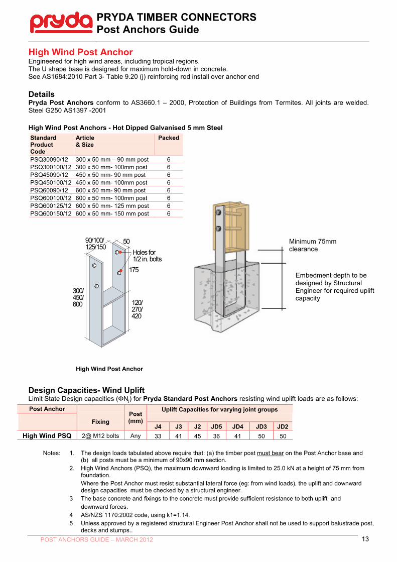
High Wind Post Anchor Engineered for high wind areas, including tropical regions. The U shape base is designed for maximum hold-down in concrete. See AS1684:2010 Part 3- Table 9.20 (j) reinforcing rod install over anchor end Details Pryda Post Anchors conform to AS3660.1 – 2000, Protection of Buildings from Termites. All joints are welded. Steel G250 AS1397 -2001 High Wind Post Anchors - Hot Dipped Galvanised 5 mm Steel Standard Product Code
Article & Size
Packed
PSQ30090/12 300 x 50 mm – 90 mm post 6 PSQ300100/12 300 x 50 mm- 100mm post 6 PSQ45090/12 450 x 50 mm- 90 mm post 6 PSQ450100/12 450 x 50 mm- 100mm post 6 PSQ60090/12 600 x 50 mm- 90 mm post 6 PSQ600100/12 600 x 50 mm- 100mm post 6 PSQ600125/12 600 x 50 mm- 125 mm post 6 PSQ600150/12 600 x 50 mm- 150 mm post 6 High Wind Post Anchor Design Capacities- Wind Uplift Limit State Design capacities (ΦNj) for Pryda Standard Post Anchors resisting wind uplift loads are as follows: Post Anchor
Post (mm)
Uplift Capacities for varying joint groups
Fixing J4 J3 J2 JD5 JD4 JD3 JD2
High Wind PSQ 2@ M12 bolts Any 33 41 45 36 41 50 50 Notes:
1.
The design loads tabulated above require that: (a) the timber post must bear on the Post Anchor base and (b) all posts must be a minimum of 90x90 mm section.
2. High Wind Anchors (PSQ), the maximum downward loading is limited to 25.0 kN at a height of 75 mm from foundation. Where the Post Anchor must resist substantial lateral force (eg: from wind loads), the uplift and downward design capacities must be checked by a structural engineer.
3 The base concrete and fixings to the concrete must provide sufficient resistance to both uplift and downward forces.
4 AS/NZS 1170:2002 code, using k1=1.14. 5 Unless approved by a registered structural Engineer Post Anchor shall not be used to support balustrade post,
decks and stumps..
120/270/420
300/450/600
175
5090/100/125/150
Holes for 1/2 in. bolts
Minimum 75mm clearance
Embedment depth to be designed by Structural Engineer for required uplift capacity
PRYDA TIMBER CONNECTORS Post Anchors Guide
POST ANCHORS GUIDE – MARCH 2012 14
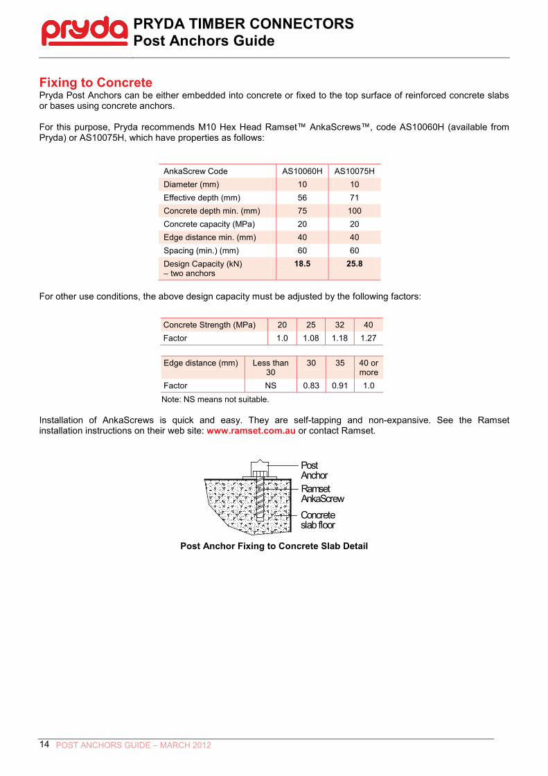
Fixing to Concrete Pryda Post Anchors can be either embedded into concrete or fixed to the top surface of reinforced concrete slabs or bases using concrete anchors. For this purpose, Pryda recommends M10 Hex Head Ramset™ AnkaScrews™, code AS10060H (available from Pryda) or AS10075H, which have properties as follows:
AnkaScrew Code AS10060H AS10075H Diameter (mm) 10 10 Effective depth (mm) 56 71 Concrete depth min. (mm) 75 100 Concrete capacity (MPa) 20 20 Edge distance min. (mm) 40 40 Spacing (min.) (mm) 60 60 Design Capacity (kN) – two anchors
18.5 25.8
For other use conditions, the above design capacity must be adjusted by the following factors:
Concrete Strength (MPa) 20 25 32 40 Factor 1.0 1.08 1.18 1.27
Edge distance (mm) Less than
30 30 35 40 or
more Factor NS 0.83 0.91 1.0
Note: NS means not suitable. Installation of AnkaScrews is quick and easy. They are self-tapping and non-expansive. See the Ramset installation instructions on their web site: www.ramset.com.au or contact Ramset.
Ramset AnkaScrewConcrete slab floor
PostAnchor
Post Anchor Fixing to Concrete Slab Detail
PRYDA TIMBER CONNECTORS Post Anchors Guide
POST ANCHORS GUIDE – MARCH 2012 15