provided by the author(s) and university college dublin ... · table 1: thermal endurance factor...
TRANSCRIPT
Provided by the author(s) and University College Dublin Library in accordance with publisher
policies. Please cite the published version when available.
Title Thermal shock resistance of polycrystalline cubic boron nitride
Authors(s) Carolan, Declan; Ivankovic, Alojz; Murphy, Neal
Publication date 2012-08
Publication information Journal of the European Ceramic Society, 32 (10): 2581-2586
Publisher Elsevier
Item record/more information http://hdl.handle.net/10197/4613
Publisher's statement This is the author's version of a work that was accepted for publication in Journal of the
European Ceramic Society. Changes resulting from the publishing process, such as peer
review, editing, corrections, structural formatting, and other quality control mechanisms may
not be reflected in this document. Changes may have been made to this work since it was
submitted for publication. A definitive version was subsequently published in Journal of the
European Ceramic Society (32, 10, (2012)) DOI:
http://dx.doi/org/10.1016/j.jeurceramsoc.2012.03.013
Publisher's version (DOI) 10.1016/j.jeurceramsoc.2012.03.013
Downloaded 2020-03-21T16:26:30Z
The UCD community has made this article openly available. Please share how this access
benefits you. Your story matters! (@ucd_oa)
Some rights reserved. For more information, please see the item record link above.

Thermal Shock Resistance of Polycrystalline Cubic
Boron Nitride
D. Carolana,∗, A. Ivankovica, N. Murphya
aSchool of Mechanical and Materials Engineering, University College Dublin, Ireland
Abstract
The effect of thermal shock on the flexural strength has been investigated ex-
perimentally. It was found that the variation in flexural strength with quench
temperature was influenced by the CBN grain size. Polycrystalline material
containing small CBN grains showed a discontinuous drop in measured flex-
ural strength above a material dependent critical quench temperature dif-
ference, ∆Tc. The sharp decrease in measured strength is accompanied by
unstable crack propagation. Material containing a significantly larger CBN
grain size, exhibited a gradual decrease in strength above the critical quench
conditions. The experimental observations agreed with an established theory
developed for thermal shock of alumina. The theoretically calculated crit-
ical temperatures agree well with the observed experimental data for each
material when a flaw size equal to the CBN grain size is employed.
Keywords: Cubic Boron Nitride, fracture, thermal shock
∗Corresponding AuthorEmail address: [email protected] (D. Carolan)
Preprint submitted to Journal of the European Ceramic Society. January 19, 2012

1. Introduction
Polycrystalline Cubic Boron Nitride (PCBN) is a super hard material
used in the machining of hardened steels, aerospace grade alloys and other
abrasive materials [1, 2, 3]. In these applications the tools are subjected to
high operating temperatures, abrasion and impact loading. This can lead
to the brittle fracture of the tool. Accurate determination of the fracture
characteristics of PCBN under a wide range of loading rates and temperatures
is therefore essential in order to evaluate the performance of the tool under
these highly demanding operating conditions. The current work examines the
thermal shock performance of two grades of PCBN. Thermal shock occurs
when a material is exposed to temperature extremes in a short period of
time. Under these conditions, the material is not in thermal equilibrium,
and internal stresses may be sufficient to cause fracture of the material. The
ability to withstand thermal shock is a function of several variables, including
the thermal conductivity, k, the coefficient of thermal expansion, α and the
specific heat capacity, c. Winkleman and Schott [4] proposed an empirical
parameter they called the coefficient of thermal endurance which gives a
qualitative estimate of the ability of a material to withstand thermal shock.
Eth =F
αE
√k
ρc(1)
where Eth is the coefficient of thermal endurance, not to be confused with the
Young’s modulus E, which appears on the right hand side of Equation 1 and
F is the material tensile strength. Selected coefficients of thermal endurance
are given in Table 1 [6]. It is significant to note the large difference in thermal
endurance between cubic boron nitride and a variety of typical PCBN binder
2

phases. This is an indicator that fracture of polycrystalline cubic boron
nitride may be a thermally controlled phenomenon. A theoretical analysis of
Material Eth
Cubic Boron Nitride 648
Diamond (Type IIA) 30.29
Aluminium Nitride 2.325
Silicon Carbide 1.4
Alumina (99%) 0.640
Alumina (96%) 0.234
Table 1: Thermal endurance factor for selected materials.
crack propagation in brittle ceramics under the influence of thermal stresses
was conducted by Hasselman and others [5, 7]. They found that for a material
with small cracks, which propagate kinetically on initiation, the crack length
and material strength are expected to change with the severity of quench,
shown schematically in Figure 1. Specimens with initial crack lengths longer
than some critical value were found to propagate stably. Further to this,
Gupta [8] found for alumina of varying grain sizes the extent of unstable crack
propagation was inversely proportional to the grain size of the material. More
recently several researchers have applied the analysis to composite ceramic
materials [9, 10, 11, 12] as well as functionally graded ceramics [13]. A
significant result from the work by Hasselman and others [5] is the difference
between resistance to crack initiation and resistance to crack propagation.
3
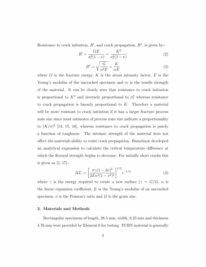
Resistance to crack initiation, R′, and crack propagation, R′′, is given by:-
R′ =GE
σ2t (1 − ν)
=K2
σ2t (1 − ν)
(2)
R′′ =
√G
α2E=
K
αE(3)
where G is the fracture energy, K is the stress intensity factor, E is the
Young’s modulus of the uncracked specimen and σt is the tensile strength
of the material. It can be clearly seen that resistance to crack initiation
is proportional to K2 and inversely proportional to σ2t whereas resistance
to crack propagation is linearly proportional to K. Therefore a material
will be more resistant to crack initiation if it has a larger fracture process
zone size since most estimates of process zone size indicate a proportionality
to (K/σ)2 [14, 15, 16], whereas resistance to crack propagation is purely
a function of toughness. The intrinsic strength of the material does not
affect the materials ability to resist crack propagation. Hasselman developed
an analytical expression to calculate the critical temperature difference at
which the flexural strength begins to decrease. For initially short cracks this
is given as [5, 17]:-
∆Tc =
[πγ(1 − 2ν)2
2Eα2(1 − ν2)2
]1/2c−1/2 (4)
where γ is the energy required to create a new surface (γ = G/2), α is
the linear expansion coefficient, E is the Young’s modulus of an uncracked
specimen, ν is the Poisson’s ratio and D is the grain size.
2. Materials and Methods
Rectangular specimens of length, 28.5 mm, width, 6.25 mm and thickness
4.76 mm were provided by Element 6 for testing. PCBN material is generally
4

sintered under high temperature (1200◦C - 1500◦C), high pressure (4 GPa -
7 GPa) conditions. Two grades of PCBN material were provided. The first
grade, denoted PCBN A has a grain size of 22 µm, with 90% vol. CBN grains.
The second grade, denoted PCBN B has a grain size of 1 µm with a lower
volume percent of CBN, approximately 60%. The binder phase for PCBN A
is best described as aluminium based ceramic, while for PCBN B the binder
is a typical titanium carbo-nitride binder. Typical micrographs for the two
materials under investigation are given in Figure 2. Thermal constants for
the constituent materials of both PCBN A and PCBN B are shown in Table
2 [18]. In total 84 samples were tested in three point bending, 46 for PCBN
PCBN A PCBN B
GPCBN [J/m2] 70 11
D [µm] 22 1
ECBN [GPa] 800 800
νCBN 0.14 0.14
αCBN [10−6/K] 1.2 1.2
Ebinder [GPa] 315 250
νbinder ≈0.2 ≈0.2
αbinder [10−6/K] 4.8 9.4
Table 2: Thermal properties of PCBN grades and binder constituents [18].
A and 46 for PCBN B. For each grade, 15 were samples were tested in the
as-received condition and a full Weibull analysis of the strength was carried
out [19]. A full description of the Weibull’s method is given in [20]. The
important outputs from the analysis are the characteristic strength, σ0 and
5

the Weibull modulus, m, a measure of the degree of scatter of the data. The
flexural strength of each sample was calculated via Equation 5 in accordance
with BS-EN 843:1 [21] where σf is the flexural strength, Pin is the breaking
load, b is the width, h is the height and s is the span of the supporting rollers.
The samples were loaded to fracture using a constant crosshead displacement
rate of 1 mm/min.
σf =3Pins
2bh2(5)
The remaining samples were then subjected to a variety of heat treatments,
water quench with quench temperature difference, ∆T , varying between
220◦C and 1080◦C, oil quench, 220◦C < ∆T < 1080◦C and water quench
with subsequent anneal. The oil used was a light grade oil. Approximate heat
transfer coefficients for unagitated water, oil and air quenching are give in
Table 3. For each heating cycle, samples were heated at a rate of 40◦C/min
Quench Media h [W/m2K]
Water 5000
Oil 2000
Air 200
Table 3: Approximate heat transfer coefficients for various media.
up to the required holding temperature and then held at that temperature
for a period of one hour. The annealing temperature in all cases was the same
as the quench temperature and the anneal hold time was 2 hours. After an-
nealing the samples were allowed to cool slowly in the closed furnace. They
were subsequently fractured in three point bend using the method previously
described.
6

3. Results and Discussion
Flexural strength results for both grades of PCBN investigated are pre-
sented in Figure 3. The Weibull modulus, m, was lower for PCBN B, m =
7.4, than for PCBN A, m = 15.7, indicating a greater scatter in strength
data for the smaller grained material. Figures 4 and 5 present the results
of the various heat treatments, oil quench, water quench and water quench
with subsequent annealing from the quench temperature on both PCBN A
and PCBN B. PCBN A exhibits stable crack propagation for water anneal-
ing at all levels of quench as explained in Figure 1. The maximum quench
temperature difference, 1080◦C, resulted in a drop in strength to 87.6 MPa,
20% of the as-received value. Oil quenching had no effect on the measured
flexural strength of PCBN A. An oil quench on PCBN B has the effect of in-
creasing the average flexural strength. The oil quench, which is a less severe
quench than a water quench, may have had the effect of relieving the existing
residual stress field, caused by the sintering and machining of the sample. A
severe water quench causes a large discontinuous drop in flexural strength
for a quench temperature difference of between 240◦C and 375◦C. This type
of behaviour can be termed unstable crack growth as explained previously
in Figure 1. Below 240◦C no drop in flexural strength was recorded. The
flexural strength recorded for a quench temperature difference of 780◦C and
above was very low, (≈ 25 MPa). It was noted that the failure was very
low energy and the fracture initiated from the centre of the sample. This is
clearly illustrated in Figure 6. The failed material also exhibited long un-
opened cracks extending from the initiation site to the edge of the sample
as shown in Figure 7. A significant surface colour change was also noted
7

on quenching at these temperatures, from dark grey to light blue and upon
microscopic investigation, significant voids close to the surface were noted
as shown in Figure 8. It is thought that this colour changes is a result of
the oxidation of titanium based binder near the surface. This has not been
investigated further in this work. It was found that simply heating either ma-
terial up to a temperature following by slow cooling in the furnace showed
no change in the measured value of flexural strength for PCBN B. Therefore
furnace heating alone does little to anneal the residual stresses and there ex-
ists some intermediate rate of cooling which appears to be beneficial in terms
of the measured flexural strength at least for PCBN A. Using the thermal
properties for the binders in both cases from Table ?? in conjunction with
Equation 4, we find that for an initial crack length, c, equal to the average
CBN grain size, D, of the material, ∆Tc= 326◦C for PCBN A and 319◦C
for PCBN B. This prediction agrees with the experimental data shown in
Figures 4 and 5. If, on the other hand, the critical temperature is calculated
using the thermal properties of CBN grains, ∆Tc = 1070◦C for PCBN A
and 1990◦C for PCBN B. The available data on the thermal properties of
the composite materials, i.e. binder and CBN together, are obtained under
steady-state experimental conditions and do not take account of any tran-
sient behaviour which may occur for short time intervals. It is important to
note that the thermal properties presented in Table 2 are room temperature
values. However work by Carolan [22] has shown that the bulk thermoelas-
tic properties of both PCBN A and PCBN B are not significantly affected
by a global increase in temperature up to 800◦C. Thus, the use of room
temperature properties in the thermal shock calculations is justified.
8

4. Conclusion
The thermal shock resistance of two grades of PCBN material is de-
termined experimentally by measuring the flexural strength of the material
after being subjected to a quench treatment. It was found that the thermal
shock resistance of the material was governed by the thermal properties of
the binder phase and not by the thermal properties of either the composite
materials or the CBN grains. However the size of the CBN grains plays an
important role in determining the type and extent of crack propagation. It
was shown that the crack can propagate either kinetically or quasi-statically
depending on the initial crack length. Excellent agreement was found with
an existing theory of thermal shock developed for monophase materials if the
initial crack length was assumed to be a flaw of one CBN grain in length.
Microscopic examination of fracture surfaces revealed that the locus of fail-
ure for severely quenched material was located in the centre of the specimen
where tensile residual stresses are known to occur as a result of the rapid
cooling. It is concluded that the theory developed by Hasselman sufficiently
describes the thermal shock characteristics of PCBN.
5. Acknowledgements
The authors are grateful to Dr. Alun Carr and Dr. Kenneth Stanton for
helpful discussions. This research was made possible by the financial support
of Element 6 Ltd, The Irish Research Council for Science, Engineering and
Technology and Enterprise Ireland.
9

References
[1] P. Heath, Properties and uses of Amborite, Carbide and Tool Journal
19 (2) (1987) 12–22.
[2] M. Fleming, A. Wickham, PCBN in the automotive industry, Industrial
Diamond Review 2 (2006) 26–32.
[3] M. Cook, P. Bossom, Trends and recent developments in the material
manufacture and cutting tool application of polycrystalline diamond and
polycrystalline cubic boron nitride, International Journal of Refractory
Metals and Hard Materials 18 (2000) 147–152.
[4] A. Winkleman, O. Schott, Ueber thermische widerstaas-scoefficienten
verschnieder glaser in iherer Abhangigkei von der chemischen zusam-
mensetzung, Ann’n. Phys. Chem. 51 (1894) 1893–1894.
[5] D. Hasselman, Unified theory of thermal shock fracture initiation and
crack propagation in brittle ceramics, Journal of the American Ceramic
Society 52 (1969) 600–604.
[6] C. Harper, Handbook of Ceramics, Glasses and Diamonds, Mc Graw
Hill, New York, 2001.
[7] D. Larson, J. Coppola, D. Hasselman, R. Bradt, Fracture Toughness and
Spalling behaviour of High Al2O3 Refractories, Journal of the American
Ceramic Society 57 (1974) 417–421.
[8] T. Gupta, Strength degradation and crack propagation in thermally
10

shocked Al2O3, Journal of the American Ceramic Society 55 (1972) 249–
253.
[9] C. Aksel, P.D. Warren, Thermal shock parameters [R’, R” and R”’] of
magnesia-spinel composites, Journal of the European Ceramic Society
23 (2003) 301–308.
[10] L. Wang, J.L. Shi, J.H. Gao, D.S. Yan, influence of tungsten carbide
particles on resistance of alumina matrix ceramics to thermal shock,
Journal of the European Ceramic Society 21 (2001) 1213–1217.
[11] J.K. Chen, K.L. Tang, J.T. Chang, Effects of zinc oxide on thermal shock
behavior of zinc sulfide-silicon dioxide ceramics, Ceramics International
35 (2009) 2999–3004.
[12] X.Q. Zhou, T.Z. Si, N. Liu, P.P. Ren, Y.D. Xu, J.P. Feng, Effect of
grain size on thermla shock resistance of Al2O3-TiC ceramics, Ceramics
International 31 (2005) 33–38.
[13] J. Zhao, X.ZAi, J. Deng, J. Wang, Thermal shock behaviours of func-
tionally graded ceramic tool materials, Journal of the European Ceramic
Society 24 (2004) 847–854.
[14] G. Irwin, Structural aspects of brittle fracture, Applied Materials Re-
search 3 (1964) 65–81.
[15] K. Ando, B. Kim, M. Iwasa, N. Ogura, Process zone size failure criterion
and probabilistic fracture assessment curves for ceramics, Fatigue and
Fracture of Engineering Materials and Structures 15 (1992) 139–149.
11

[16] T. Anderson, Fracture Mechanics - Fundamentals and Applications, 2nd
Edition, CRC Press, Boca Raton, 1995.
[17] W. Kingery, H. Bowen, D. Uhlmann, Introduction to Ceramics, 2nd
Edition, John Wiley and Sons, New York, 1976.
[18] R. Riedel, Handbook of Ceramic hard Materials, in: Volume 2, Wiley
VCH, Weinheim, 2000.
[19] W. Weibull, A statistical theory of the strength of materials, Ingenio-
ersvetenskapsakad, Handl, 151 (1939) 1–45.
[20] J.B. Wachtman, Mechanical Properties of Ceramics, John Wiley and
Sons, New York, 1996.
[21] BSI, Advanced Technical Ceramics - Mechanical properties of mono-
lithic ceramics at room temperature. PArt 1: Determination of flexural
strength. BS 843-1, British Standards Institution, 2006.
[22] D. Carolan, Mechanical and Fracture Properties of Polycrystalline Cubic
Boron Nitride as a Function of Rate and Temperature, PhD Thesis,
University College Dublin, 2011.
12

!"#$%&'()*+,&
-+"()*+,&
.(/0("#+1"(&234("()$(& .(/0("#+1"(&234("()$(&
.(/0("#+1"(&234("()$(&.(/0("#+1"(&234("()$(&
5#6&
5#6&
576&
576&
Figure 1: Crack propagation and strength for unstable (a) and stable (b)
crack propagation conditions [5].
13

(a) PCBN A
(b) PCBN B
Figure 2: Scanning electron micrographs of PCBN A and PCBN B showing
CBN particles (dark phase).
-4 -3 -2 -1 0 1 2 3
5.9 6 6.1 6.2 6.3
ln(l
n(1
/Ps)
)
ln(!)
(a) PCBN A
-4
-3
-2
-1
0
1
2
6 6.2 6.4 6.6 6.8
ln(l
n(1
/Ps)
)
ln(!)
(b) PCBN B
Figure 3: Weibull plot of strength data for (a) PCBN A (n = 15, m = 15.7,
σ0 = 438 MPa) and (b) PCBN B (n = 15, m = 7.4, σ0 = 670 MPa).
14

!"
#!!"
$!!"
%!!"
&!!"
'!!"
(!!"
!" $!!" &!!" (!!" )!!" #!!!" #$!!"
!!"#
$%&'(
)*+&
",&'$&-+&
*+,-."/0-123-4" *+,-."/0-123-45611-+7-4" 897"/0-123-4"
":2";"%$(<"="
Figure 4: Flexural strength of PCBN A quenched in water and subsequent
annealing from quench temperature as a function of quench temperature
difference [∆T ].
!"
#!!"
$!!"
%!!"
&!!"
'!!!"
'#!!"
!" #!!" $!!" %!!" &!!" '!!!" '#!!"
!!"#
$%&'(
)*+&
",&'$&-+&
()*+,"-.+/01+2" 345"-.+/01+2"
"60"7"8'9:";"
Figure 5: Flexural strength of PCBN B quenched in oil and water as a
function of quench temperature difference [∆T ].
15

Tramline cracks
Large oblong holes in fracture surface
Failure initiation
Figure 6: SEM Micrographs showing main features of quench failure of PCBN
B.
16

Figure 7: Knitted SEM micrograph of long unopened crack extending from
failure initiation region to edge of sample.
!"#$%&%"'()
Figure 8: Fracture surface of PCBN B flexural strength sample, quenched
from 1100◦ C. Microscopic voids are clearly evident close to the surface which
are not present in the unquenched sample.
17