prototyping redesign and production plan...
TRANSCRIPT

BACHELOR THESIS
A solar lantern for the rural population of Cambodia
PROTOTYPING, REDESIGN AND PRODUCTION PLAN FOR THE
ANGKOR LIGHT
Martijn Kranen Industrial Design Engineering University of Twente October 2007
Mrs. dr. Angèle Reinders – University of Twente Ir. Henry de Gooijer – Kamworks Arjen Luxwolda – Kamworks Commissioned by Kamworks

BACHELOR THESIS
PROTOTYPING, REDESIGN AND PRODUCTION PLAN FOR THE
ANGKOR LIGHT
A SOLAR LANTERN FOR THE RURAL POPULATION OF CAMBODIA
Martijn Kranen Industrial Design Engineering University of Twente October 2007 Mrs. dr. Angèle Reinders – University of Twente Ir. Henry de Gooijer – Kamworks Arjen Luxwolda – Kamworks Commissioned by Kamworks

Bachelor Report Angkor Light
Intr
oduc
tion
2
PREFACE This project really was an eye-opener for me in different ways. As a designer I went to a world completely
different from the one I am used to live in and it therefore really required another view on designing. For
example efficiency was not a main priority, contrary to the need to produce the product locally (almost)
regardless of the amount of extra hours per product added.
Personally I experienced that living in a
poor country marks the relativity of the
wealth of our Western world. Our hunt
for more and better things sometimes
intends to overshoot in the materialistic
direction. People living in the most
sober circumstances with great
pleasure and joy point out that
belongings are not (always) the way to
happiness. Severe poverty on the other
hand makes life extreme difficult and
having some products to help during
the daily activities really can make a
difference.
My motivation to start this project was to go abroad to a total different country in the first place. Also the
ability to contribute to a sustainable product was a big consideration. During the project my view on the best
way to help third world countries changed a little. We can and should provide the knowledge to help these
people but should not judge the
culture of a country from a strictly
Western point of view. Trying to
understand why people act the way
the do really helps in this process and
providing education can help them to
develop themselves and their country.
Working with local people and
attending a class at the University of
Leap was a nice way to get acquainted
with the Cambodian culture. At the
start I was overwhelmed with the
attention given to all western people,
everyone was looking at us and in the
more rural areas people are even
waving and shouting (especially the
children). After a while I got used to
this phenomenon, but it was nice to
see that I was not the only one seeing
new things.
I had real fun with the Cambodian employees of Kamworks, with the other students and the kids at the
orphanage, who were always smiling. Exploring the country by motorbike revealed a lot of things tourists
FIGURE 2: THE STUDENTS AT KAMWORKS (EXCEPT BAS)
FIGURE 1: CHILDREN FROM THE VILLAGE

Bachelor Report Angkor Light
Intr
oduc
tion
3
normally don’t see and meeting people who normally
don’t see tourists. It was a beautiful way to explore
Cambodia and its natural and cultural treasures.
I want to thank the following people who helped me to
complete this project: Arjen for his help and endless
patience while answering a lot of questions. I also want to
thank him for the constructive discussions we had about
the production process. Henry for his support and critical
eye while watching at a distance from the Netherland.
Leap for his endless smiles and stories about Cambodia
and its people and for showing us around. Sarin and Sita
for their help in the workshop and a wonderful insight in
the Cambodian way of living. Last but not least I want to
thank Angèle Reinders for her support from the
Netherland, especially helping to achieve things difficult to
arrange at the University.
A special thanks goes to Loes and my family for their
support and motivation while being far away from home.
Martijn Kranen
FIGURE 4: LEAP, CAMBO DIAN STUDENT, TRANSLATO R
AND FRIEND
FIGURE 3: DAILY WASHING OF THE COWS

Bachelor Report Angkor Light
Intr
oduc
tion
4
SUMMARY
INTRODUCTION
This report is the result of a bachelor graduation project at the University of Twente commissioned by
Kamworks, a small Cambodian company founded by the Dutch charity foundation Pico Sol. The company itself
aims at the production and sale of affordable PV products for the rural consumer market in Cambodia. The
project covers the prototyping, the redesign and the design of the production plan for a solar lantern.
THE PROBL EM
Cambodia is a country with limited power resources. About 90% of the Cambodian households have no access
to electricity infrastructure for reliable lighting. These people are also very poor and live below the poverty line
of less than 1$ per day. Needs like lightning are not obviously catered for, because of this limited power
availability. The alternative, using a fuel lamp, is very expensive because of the high fuel price.
Another problem Cambodia faces is the unemployment rate. General wages are low and because of the
turbulent history about 60% of the population is 20 years or younger. Job opportunities for this group are very
low.
ANALYSIS OF THE EXIS TING LANTERN
The project started at Kamworks aims to solve a part of both problems described. In association with the Delft
University the first version of a solar lantern has been developed, delivering both an affordable lightning
solution to the rural population and work opportunities to young Cambodians. This version of the lantern was
designed by Stephen Boom in 2005 as a result of a master graduation project. The complete design process
was done in the Netherland, exact for a field study of about 6 weeks. The lantern had not been produced and
tested locally and exact knowledge of the Cambodian situation was not always available during the design
process.
This project started with a global analysis of the situation and the problem. Next the existing prototype of the
lantern was reproduced in Cambodia, followed by a general analysis of the result and the production process.
Several tests were done with this prototype, including a drop test, a water test and a user test to determine
deficiencies of the product.
REDESIGN OF THE LANTERN
Using the requirements formulated by the company and the deficiencies found a redesign was carried out.
Every aspect was looked after, but special attention was given to a low price for the product and the possibility
to produce it locally. Inquiries were done to obtain the lowest price for components used.
The product was altered to be waterproof, to be more resistible against dropping on the ground and to be
easier to produce at Kamworks.

Bachelor Report Angkor Light
Intr
oduc
tion
5
DESIGN OF TH E PRODUCTI ON PLAN
The production of a product in Cambodia differs a lot from a situation in the Netherland. Production aspects
like availability of machines and labour were examined and potential problems were investigated. Based on
the findings the design of the product was altered and a production plan was made. Several tools including
moulds and bending aids were designed and tested. An scheme was made to describe the assembly of the
total product.
RESULTS
The results of this assignment are a prototype, a complete redesign of the lantern and a production plan
including the design of the tools needed.

Bachelor Report Angkor Light
Intr
oduc
tion
6
TABLE OF CONTENTS
PREFACE 2
SUMMARY 4
TABLE OF CONTENTS ................................................................................................. 6
1 INTRODUCTION .................................................................................................... 8 1.1 Background......................................................................................................................................... 8 1.2 Assignment ......................................................................................................................................... 9 1.3 Naming convention ........................................................................................................................... 10
2 GENERAL ANALYSIS ............................................................................................. 11 2.1 Introduction...................................................................................................................................... 11 2.2 Cambodia ......................................................................................................................................... 11 2.3 Language .......................................................................................................................................... 11 2.4 Market situation ............................................................................................................................... 12 2.5 Electricity in rural Cambodia ............................................................................................................. 13 2.6 Solar Energy ...................................................................................................................................... 13 2.7 Lightning in rural Cambodia .............................................................................................................. 14 2.8 The SOLantern .................................................................................................................................. 15
3 TECHNICAL ANALYSIS OF THE SOLANTERN ................................................................. 19 3.1 Introduction...................................................................................................................................... 19 3.2 Recommendations and results out of previous research .................................................................... 19 3.3 Reproducing the prototype ............................................................................................................... 20 3.4 Prototype testing .............................................................................................................................. 25 3.5 Competitors ...................................................................................................................................... 27 3.6 Standards ......................................................................................................................................... 28 3.7 Changed boundary conditions ........................................................................................................... 29 3.8 List of requirements of the Angkor Light ............................................................................................ 30 3.9 Deficiencies of the product ............................................................................................................... 31 3.10 Conclusions....................................................................................................................................... 32
4 DESIGN OF THE ANGKOR LIGHT .............................................................................. 33
4.1 Introduction...................................................................................................................................... 33 4.2 General product layout ..................................................................................................................... 33 4.3 Reflector ........................................................................................................................................... 34 4.4 Top casing ......................................................................................................................................... 35 4.5 Inner top casing ................................................................................................................................ 35 4.6 Base casing ....................................................................................................................................... 36 4.7 Handle .............................................................................................................................................. 37 4.8 Internal frame ................................................................................................................................... 37 4.9 Electronics ........................................................................................................................................ 38 4.10 Front plate ........................................................................................................................................ 41 4.11 Mechanical connections .................................................................................................................... 42 4.12 Electrical connections ....................................................................................................................... 42 4.13 Battery ............................................................................................................................................. 43

Bachelor Report Angkor Light
Intr
oduc
tion
7
4.14 Materials .......................................................................................................................................... 44 4.15 Colours ............................................................................................................................................. 45 4.16 Cost price.......................................................................................................................................... 45 4.17 Packaging ......................................................................................................................................... 47 4.18 The final product............................................................................................................................... 48
5 PRODUCTION .................................................................................................... 51 5.1 Introduction...................................................................................................................................... 51 5.2 Production situation ......................................................................................................................... 51 5.3 Employees ........................................................................................................................................ 51 5.4 Production equipment ...................................................................................................................... 51 5.5 Mould design .................................................................................................................................... 53 5.6 Production process ........................................................................................................................... 55 5.7 Metal parts ....................................................................................................................................... 56 5.8 Production guide .............................................................................................................................. 57 5.9 Assembly .......................................................................................................................................... 59
6 CONCLUSIONS AND RECOMMENDATIONS ................................................................... 60 6.1 Meeting the requirements ................................................................................................................ 60 6.2 Recommendations ............................................................................................................................ 62
7 LIST OF DEFINITIONS ........................................................................................... 64
8 LITERATURE ...................................................................................................... 65

Bachelor Report Angkor Light
Intr
oduc
tion
8
1 INTRODUCTION
1.1 BACKGROUND This report is the result of a bachelor project at the department of Industrial Design Engineering of the
University of Twente. It covers the redesign of a solar lantern for the rural population of Cambodia. The project
was commissioned by Kamworks, a small solar company in Cambodia.
1.1.1 KAMWORKS Kamworks is a young Cambodian PV company with Dutch founders. This initiative arises out of Pico Sol, an also
Dutch independent charity organization which makes an effort to help the small-scale application of solar
energy in third world countries. The company itself aims at affordable PV products for the rural consumer
market in Cambodia. About 90 percent of the population of this country has no access to electricity.
The goal of Kamworks is being expressed in their mission statement: “Affordable energy for sustainable
development”. At the moment the main focus lies on installing so called Solar Home Systems at orphanages,
churches, schools etc. These activities will be extended with the production of commercial consumer PV
products.
Kamworks is located in a village named Sré Ampil, 40 km south-east from Phnom Penh, on the grounds of an
orphanage (see Appendix O ). One of the problems these orphans come across is finding a job when they are
leaving the orphanage. Cambodia is mainly a traditional agricultural society and children usually continue with
the business of their parents. Kamworks tries to establish some jobs by employing them to produce
sustainable energy products. In this way both the environment and the orphans gain profit.
The University of Twente is an entrepreneurial research university. It offers education and research in areas
ranging from public policy studies and applied physics to biomedical technology. The discipline Industrial
Design Engineering focuses on the design of mass produced (consumer) products. The bachelor project is the
final assignment of three years of the bachelor program.
FIGURE 5: THE KAMWORKS BUILDING AT THE ORPHANA GE

Bachelor Report Angkor Light
Intr
oduc
tion
9
1.2 ASSIGNMENT 1.2.1 BAC KGROUND OF THE PROBLEM At this moment the rural population of Cambodia does not have a solution for affordable permanent indoor
lighting. Indoors and in improvised stores under their house people make use of kerosene lamps and lighting
powered by generators and batteries. Outdoor lightning solutions only consist of small torches powered by
expensive batteries. Although there is a demand for both permanent indoor and movable outdoor lightning no
affordable products are available.
With five full hours of sun per day and a balanced distribution over the year, Cambodia is one of the sunniest
countries in the world. Because of this fact, the potential for successful solar powered products is very high. To
utilise this potential in 2005 Stephen Boom of Delft University of Technology carried out a Master thesis with
the goal to design a solar lantern. In October of that year he finished this project resulting in the SOLantern. At
the moment a prototype of this lantern is made, but it is not ready yet for mass production.
1.2.2 ASSIGNMENT DESC RIPTION The goals of this assignment are to redesign the SOLantern to make it useable and affordable for the target
group and make it producible in Cambodia. The assignment consists of the analysis of the current design, the
redesign of the lantern and the production plan.
At the completion of the assignment a pre-production series of about 20 pieces must be able to be produced
using the designed production plan. Next extensive user tests can be performed with these products by the
company.
1.2.3 S ITUATION To get a good idea of the local situation, the end users and the production capabilities the assignment will be
carried out in Cambodia. A team of 6 students will be working on different parts of the lantern and its
distribution system (see Appendix A for more information).
1.2.4 FRAMEWORK The approach that will be followed consists of several parts (Figure 6).
The general analysis consists of reading lecture and papers concerning the lantern, e.g. the reports of Stephen
Boom (Boom, 2005) and Mando Rotman (Rotman, 2006). Also the local situation in Cambodia will be explored
and the rural population will be questioned about the prototype.
The technical analysis will be done by the local reproduction of the prototype, by performing several tests with
this prototype and by the analysis of the competitors. Also an examination about the availability of materials
and a cost price analysis will be performed.
After gathering this data a redesign of the lantern will be performed to fulfil the demands.
FIGURE 6: PROCESS OF THE PROJECT
General analysis Technical analysis Redesign Production
implementation

Bachelor Report Angkor Light
Intr
oduc
tion
10
To produce a pre-production series and a subsequent production of about 400 products the implementation of
the production is carried out. This will result in the production of this pre-production series which will be used
to perform some final tests.
The timeframe of this assignment will be three months.
1.3 NAMING CONV ENTION To make a clear difference between the product designed by Stephen and the redesigned one these two
versions will be referred to as SOLantern and Angkor Light respectively. The SOLantern is the name originally
chosen by Stephen. Angkor Light is the one chosen by Kamworks, reflecting the Cambodian identity of the
lantern and is also the name under which the product will be sold.

Bachelor Report Angkor Light
Gen
eral
ana
lysi
s
11
2 GENERAL ANALYSIS
2.1 INTRODUCTION Because the project is carried out in a country with huge differences compared to the Netherlands a general
analysis about the local situation is carried out. This analysis consists of an exploration of the geographic
situation, the language, the market, the energy and lightning situation. At the end of the chapter the
SOLantern is introduced and placed into the local situation.
2.2 CAMBODIA Cambodia is a country in South East Asia, bordered by
Thailand on the west and north, Laos at the north and
Vietnam at the east. It has a population of almost 15
million people (Population Reference Bureau, 2007)
covering an area of 181.035 square km (World Bank,
Environment Department, 2004) , this is about 4.5 times
the size of the Netherlands. The country is located in the
tropics. Cambodia has an average minimum temperature
of 23° and an average maximum temperature of 32° with
almost no variation during the year (The Weather
Channel, 2007).
The country is mainly known to the outside world
because of the cruelties of the Khmer Rouge regime in
the ’70, led by “Brother Number One” Pol Pot.
Nowadays the country has still not completely overcome
its history, the leaders of the regime have never been
prosecuted (Pol Pot died in freedom in 1999) and the soldiers of the regime are still walking around and could
be anyone’s neighbours without them knowing.
In two weeks after the Khmer Rouge was defeated by the Vietnamese in 1978, next the Khmer Rouge started a
guerrilla war which finally ended after the peace settlement in 1991. In 1993 the first democratic elections
were held, but even today the country is not really a democracy because corruption and intimidation are every
day’s business.
Due to the economically and technical recession during and after this period and the lack of financial support
of Western countries like neighbouring country Vietnam received, Cambodia is still a low developed country.
2.3 LANGUAGE The Khmer language is part of the Austro-Asiatic language group,
together with e.g. Vietnamese and Mon found in Thailand, Cambodia,
Burma, Vietnam and Lao (Gordon, 2005). These languages differ a lot
from Western languages in sound and writing. It has a completely
different kind of alphabet and several other sounds are used (see
Figure 8 for an example of Khmer writing). The English education is
developing but at the time almost no one speaks it at a high level making communication with local people
very difficult.
FIGURE 8: THE WO RD "CAMBODIA" IN
KHMER
FIGURE 7: GEOGRAPHIC LOCA TION OF CAMBODIA

Bachelor Report Angkor Light
Gen
eral
ana
lysi
s
12
2.4 MARKET SITUATION 2.4.1 CORRUPTION According to the Corruption Perceptions Index Cambodia was ranked 151 out of 163, meaning that it belongs
to the 15 most corrupt countries in the world (Transparency International, 2006). Compared to the 9th place of
the Netherlands it is obvious that trade is not as straightforward as in western countries. A lot of regulations
exists and officers in function don’t hesitate to ask more money purely for personal gain to get things aranged.
Going higher up in the command chain will get around this problem but is time consuming.
This fact has certain implications for product development and production in Cambodia. A longer period to get
the necessary paperwork has to be taken into account and even unpredictable incidental higher costs for
licensing and the import of products will be possible. The gouvernment is aware of the corruption problem and
is trying to organize things better for foreign companies, especially because this in the interrest of the country.
But the same corruption is causing these things to change very slow.
2.4.2 SELLING PRODUC TS Large electronic concerns do not exist in
Cambodia, instead little market shops are located
in a lot of villages. These shops sell a lot of
different products varying from ventilators to gas
stoves which make finding a certain product
sometimes difficult. Prices for products are
always established by bargaining.
A big problem for buyers in general is the
unknown quality of a product. A brand name is
no guarantee because the Cambodian market is
flooded with fake Chinese products copying
quality brands. A big challenge is to develop a
quality product and convince the people of this
fact.
FIGURE 9: A TYPICAL CAMBO DIAN MARKET SHOP

Bachelor Report Angkor Light
Gen
eral
ana
lysi
s
13
2.5 ELECTRICITY IN RURAL CAMBODIA In the rural areas of Cambodia electricity is not an obvious presence. Over 85% of the total population of
Cambodia lives in rural areas (Institut de Technologie du Cambodge, 2002) and over 85% of the total
population suffers of the lack of access to the electricity grid. Together with electricity prices of 16 c/kWh in
Phnom Penh and an average of 51 c/kWh in the rural areas Cambodia has one of the lowest electrification
rates in Asia and among the highest electricity costs in the world (Economic Consulting Associates, World Bank,
2002).
The electricity distribution differs from the distance to a
city. At the moment only 7 of the biggest cities have access
to the national power grid supplying power generated by
the national power company Electricité du Cambodge
(EDC). It is very unlikely that this company will extend the
grid to cover more than 80% of the population because of
the high costs and low gain.
The second type of power suppliers are Rural Electricity
Enterprises (REEs). Relatively small generators supply
power to one or two villages only, making a large grid not
necessary. This type of power supply is suitable for rural
areas but with the average price of 51 c/kWh very
expensive.
The third method consists of car batteries charged by local
generator shops, but this is also an expensive solution, up
to $3.5 per kWh (Economic Consulting Associates, World
Bank, 2002). The batteries are not charged with the right
current and with very inefficient diesel generators causing
very short battery life, loss of energy and a lot of pollution.
2.6 SOLAR ENERGY At the moment solar energy in Cambodia is a rare phenomenon. Some small NGOs are installing Solar Home
Systems in small villages, supplying power to one to several small households to let them use some electrical
lights and perhaps a small television if affordable.
These systems are often paid by foreign countries
as a part of an aid project.
Solar Home Systems are an effective way to
supply rural villages with electricity. The costs are
generally about $1.2/kWh (Kamworks, 2007),
mainly because of the high material and
installation costs.
Another option is to extend the electricity grid to
reach these people. This is even more expensive
and the costs also depend on the distance
between the existing grid and the area that needs to be covered. Solar energy has no need for a large grid,
resulting in the same cost per kW independent at every location with the same amount of radiation (Figure
10).
OUTSIDE THE PROVINCIAL TOWNS, POWER SUPPLY
IS RARE AND MEAGER, WITH ONLY ABOUT 6
PERCENT OF CAMBODIA’S RURAL HOUSEHOLDS
HAVING ACCESS TO ELECTRICITY SUPPLY, AND
ANOTHER 3 PERCENT OWNING SOME TYPE OF
INDIVIDUAL POWER GENERATING UNIT.
OF THE REMAINING 91 PERCENT OF THE RURAL
POPULATION, SOME 55 PERCENT USE AUTOMOBILE
BATTERIES (COSTING US$ 2.0-3.5 /KWH) FOR
OCCASIONAL AND LIMITED USE, OR DO WITHOUT
ELECTRICITY COMPLETELY (36 PERCENT)
. WORLD BANK (http://go.worldbank.org/C1KN2PJ7M0)
“
”
FIGURE 10: SOLAR ENERGY COSTS VERSUS GRID EXTENSION COS TS

Bachelor Report Angkor Light
Gen
eral
ana
lysi
s
14
2.7 LIGHTNING IN RURAL CAMBODIA Lighting in the rural areas is a matter of improvisation and creative use of available resources. At the moment
several kinds of lightning solutions exist.
2.7.1 TRADITIONAL CAMBODIAN LAMP The first one is the Traditional Cambodian lamp, a simple tin fuel
lamp (Figure 12). Kerosene is available throughout the country and
is therefore an easy way to get some light. Besides a bad smell this
solution has some other disadvantages:
Little light is produced
These kinds of lamps are unsafe because the top part becomes
too hot and can fall off easily. At that moment a fire can arise.
The lamp is useless in rainy conditions
Burning fuel is polluting to the environment
Due to the high fuel price the use of this kind of lighting is
expensive. Families using this kind of lighting spend $20-24 per
year on fuel (MIT Sloan - GLab team, 2007).
2.7.2 FLUORESC ENT TUBE Some kind of electric lighting is available. Light bulbs are very
energy consuming and are therefore not used. Fluorescent tubes
are used instead, but little is known about electricity and its safety
aspects and very bad wiring and fixation of these lights is used
often. Besides this increase of the risk of short-circuit and fire
several other problems with this kind of lightning exist:
Batteries are used carelessly, with the result of damaged
batteries and less capacity
Batteries are being charged with the inefficient generators.
The characteristics of these batteries are not taken into
account while charging resulting in overload and heavy wear.
FIGURE 11: MONTHLY AVERAGES INSOLATION IN PHNOM PENH
FIGURE 13: A HANGING FLUORES CENT
TUBE
FIGURE 12: TRADITIONA L CAMBODIAN

Bachelor Report Angkor Light
Gen
eral
ana
lysi
s
15
The charging process is very polluting because of the very inefficient generators used
2.7.3 F ISHERMAN ’S LIGHT A lighting product commonly used is the headlight for assistance by fishing
or finding frogs and is powered by a small battery. A different purpose is
the use as lighting inside a house. In this situation a car battery is used as
power supply.
The biggest problem with this headlight is the weak light bulb. User
interviews performed by Stephen Boom indicate that the bulb needs to be
replaced up to 3 times a day. The fishermen spend about $10 dollar a
month on charging of the battery and replacement of the light bulbs.
This product is a multifunctional; by removing the reflector the headlight is
transformed into an ambient light usable for indoor lightning. This
principle is used in the development of the SOLantern.
2.8 THE SOLANTERN The lantern developed by Stephen is a sustainable
solar product aimed at the needs of the rural
population.
Because a rechargeable battery and a solar panel
are used no extra costs are needed to keep it
working. The lantern should replace the two
current polluting and inefficient lighting solutions:
the traditional Cambodian lamp and the
fluorescent tube.
The chosen materials and production methods
are supposed to make it possible to produce the
lantern in Cambodia. This is not tested yet and no
local manufactures are located at this moment.
At this moment only a basic prototype of the
design is produced in the Netherlands. Several
requirements formulated by Stephen are not
evaluated yet.
FIGURE 15: PRO TOTYPE OF THE SOLANTERN
FIGURE 14: FISHERMAN’S LIGHT

Bachelor Report Angkor Light
Gen
eral
ana
lysi
s
16
2.8.1 PURPOSE OF USE The product can be used inside the house for reading, cooking and talking and outside the house for walking
and tasks like finding animals. Several general lightning categories can be determined when these tasks are
analysed (Plas, 1998). To fulfil all demanded purposes the product should be able to comply with all these
lighting categories (Table 1).
2.8.2 TARGET GROUP The target group defined by Kamworks are:
“Poor people living in rural and developing areas without a reliable access to an electricity grid”.
Poor people are those with an income of about $1 per day. The first target market will be Cambodia because
of the lack of electricity grid and the huge potential for PV products. About 5 million rural people in Cambodia
(1.1 million families) belong to the target group. Monthly expenditures of these families for lighting vary from
$1-3 per month (Boom, 2005). The product positioning is illustrated in Figure 16.
Symbol Light distribution Light fixation
General lighting Evenly distributed light around the lamp in horizontal plane
Fixated on the ground
General lighting Evenly distributed light around the lamp in horizontal plane
Fixated at the ceiling
General lighting Big bundle of light from above
Fixated at the ceiling
Task light Bright spot to see more details
Fixated at the ceiling
General lighting Big bundle of light
Mobile possible to carry in one hand.
Spot light very bright spot Mobile possible to carry in one hand
TABLE 1: LIGHTNING CATEGO RIES (BOOM, 2005)

Bachelor Report Angkor Light
Gen
eral
ana
lysi
s
17
2.8.3 SELLING MODEL At the moment a Master thesis is written
by Miriam Reitenbach about the
marketing of Kamworks’ solar products.
Several directions are being explored
varying from fixed a market stall to
altered tuk-tuks driving between villages
to sell the products.
The entrepreneurs selling will also be able
to repair products and give information
about PV to customers. An educational
program made by Jony Heerink providing
general knowledge about solar energy
and Kamworks’ vision is used to train
these people (Heerink, 2007).
2.8.4 SELLING PRIC E The target price of the solar lantern made by Stephen Boom was estimated at $50. Several market researches
confirmed this price as the maximum amount of money people are able to spend on this kind of product (MIT
Sloan - GLab team, 2007) (Rotman, 2006).
The current price estimated by Stephen is almost $63 (see Table 2), this is higher than the indication of the
amount of money the target group can spend on a lantern. Attention should be given to obtain an accurate
prediction of the real cost price and the selling price and lowering it. This can be done by enquiring a lot of
companies to get the lowest price and comparing alternatives based on price during the redesign process.
FIGURE 16: POSITIONING OF THE ANGKOR LIGHT BETWEEN THE EXISTING
SOLAR PRODUCTS (BOOM, 2005)
High
Low
$ 100 $ 200
Khmer Solar
Business to business solar companies
Angkor Light
Electronic shops in bigger cities
Complexity of the products
Price of the products
SOLAR
COMPANIES

Bachelor Report Angkor Light
Gen
eral
ana
lysi
s
18
TABLE 2: THE COST BREAKDO WN OF THE SOLANTERN
Components Price ($) Reference
Plastic components $2,77 Westward.com
Electronics $7,56 Conrad electronics
Metal components $0,09 PMB
Screws, Nuts, bolds etc $1,29 Assumption
CFL $2,10 Kamworks Chinese supplier
Battery $2,80 Kamworks Chinese supplier
Subtotal $16,61
Capital costs (machinery) $0,53 Assumption
Labor $0,25 Assumption
Transport, packaging, breakage (15%) $2,49 Business plan Kamworks
Subtotal $3,27
Distribution and marketing (14%) $6,05 Business plan Kamworks
Profit(20%) $8,64 Business plan Kamworks
Margin retailer(10%) $4,32 Business plan Kamworks
VAT(10%) $4,32 Business plan Kamworks
Subtotal $23,33
Total excl, solar panel $43,21
Solar panel: $19,50 Kamworks Chinese supplier
Total: $62,71

Bachelor Report Angkor Light
Tech
nica
l ana
lysi
s of
the
SOLa
nter
n
19
3 TECHNICAL ANALYSIS OF THE SOLANTERN
3.1 INTRODUCTION After a general analysis of situation presented in the previous chapter a technical analysis of the existing
lantern will be carried out. This will be done in the following steps:
Recommendations from previous reports about the lantern are analyzed, questions are formed based
on these recommendations
The prototype is reproduced locally to:
o do a user test, a drop test and a water test
o analyze deficiencies of the product
o analyze problems in the production process
Technical analysis of the SOLantern and its functions
A new competitor analysis is made to determine the strengths and weaknesses of the product
Answers to these questions, results from these tests and conclusions from the previous chapter are
used to determine a list of requirements and wishes for the final product
This list of requirements will be a starting-point of the concept development phase and is used to check if the
final product fulfils its needs.
3.2 RECOMMENDATI ONS AND RESULTS OUT OF PREVIOUS RESEARCH Three reports have been written (partially) about the solar lantern. The first one is the initial master-thesis of
Steven Boom about the SOLantern, the second is the internship report of Mando Rotman about Product
Market Combinations (PMCs) in Cambodian rural areas and the last one is a market research project of the
MIT about solar product and the marketing of them. In all of these report recommendations and points of
attention are written down for further investigation. A complete list (with answers) can be found in Appendix
B .The ones useful for the redesign of the lantern are extracted, put together and sorted by way to acquire the
answers.
3.2.1 REPORT STEPHEN BOOM The graduation assignment of Boom (Boom, 2005) was to design the SOLantern. His report is a reflection of
the design process, including a general analysis of the problem, the technical aspects of the lantern and a small
user evaluation at the end. Most of his considerations regarding the design are written down making it a very
useful document as a start of the redesign.
A lot of research is done in the Netherland, so very few local available materials are listed. Because this is
necessary to know when starting mass production in Cambodia it will be an important part to investigate.
3.2.2 REPORT MANDO ROTMAN Extensive field research was carried out by Rotman (Rotman, 2006) to determine possible PMCs for Kamworks
in the rural areas. Useful data about people’s earnings and willingness to pay where collected.
3.2.3 REPORT MIT The research carried out by the Massachusetts Institute of Technology (MIT Sloan - GLab team, 2007) was
done to determine

Bachelor Report Angkor Light
Tech
nica
l ana
lysi
s of
the
SOLa
nter
n
20
3.3 REPRODUCI NG THE PROTOTYPE One prototype of the lantern is made in the Netherlands by Stephen Boom. No tests with this prototype have
been done in Cambodia, only earlier prototypes have been shown to the target group. Bringing the prototype
to Cambodia is very difficult and therefore no option. By producing the prototype with local machines
advantages and problems will be known and can be taken into account while redesigning the product. For
these reasons the prototype is reproduced using local machines and locally available materials.
Because the first prototype was not fully functional and some boundary conditions have been changed, some
additions are made:
a bigger battery is used causing the bottom part to be larger
a connection to attach the solar panel is made (not implemented in the first prototype)
3.3.1 AVAILABLE MAC HINERY Cambodia is a development country and therefore it is not possible to easily get every imaginable machine to
produce the product. It is helpful to know which kinds of machines are available at the moment at Kamworks;
this can be taken into account in the design process to make the product producible. Kamworks is able to buy
some second handed machines when needed. The available machinery at Kamworks is listed in Appendix C .
The power needed is produced by the existing solar panels and an additional generator. The batteries of the
solar system have a capacity of 19.2 kWh (1800 Wp), the generator is capable of producing an extra 15 kWh.
The vacuum form machine needed about 4.73 kW for heating and another 0.75 kW for all other operations. All
other machines used only a fraction of this amount. Because of the high start-up power needed by the vacuum
forming machine and high energy use the generator must always be used during production with this machine.
3.3.2 MATERIALS
3.3.2.1 P L A S T I C S
During the reproduction period non-transparent polystyrene and acrylic with a thickness of 1.5 mm where
available at the company. Transparent acrylic (2 mm) and an acrylic-like material with a thickness of 1 mm
were found in Phnom Penh, almost the only place in Cambodia to find these kinds of materials. No other
plastics for vacuum forming were available, especially at the short-term.
Some printed overhead sheets were used to make the front panel (the button overlay). This part was put onto
the casing using two components glue.
3.3.2.2 M E T A L
Metal is widely available at local stores, including large sheets and strips. While producing the prototype not
all strips with the right width were in stock, so a metal sheet was cut into smaller pieces.
Instead of RVS as material for the handle aluminium was used, because of its availability and nice appeal.
3.3.2.3 BU Y P A R T S
Some identical 4.5 Ah batteries were available at the company with the desired voltage and size. The
connections were also positioned at the same place as the one used in Booms design so one of these batteries
was used.
CFL

Bachelor Report Angkor Light
Tech
nica
l ana
lysi
s of
the
SOLa
nter
n
21
The CFL used was a standard 5W light with a E14 connection submitting a bluish light. The lamp holder used
was a E14 fitting mounted onto the internal frame with two metal strips and some screws. The original design
consisted of a different connection not available in Cambodia.
KNO B S The knobs to attach the handle with the internal frame were taken from the Netherlands, because it was
known that they were not available in Cambodia.
3.3.3 THE PRODUC TION PROC ESS The local production of the prototype is very useful to analyze the difficulties in this process. Not only
problems regarding the product itself are discovered, also the complete production environment is tested. The
problems experienced are described in the next paragraphs, with a direction in which the solution can
probably be found.
3.3.3.1 V A C U U M F O R M I N G
At Kamworks the 3 plastic parts are made using the vacuum form machine. Vacuum forming is a process in
which thermoplastic materials are formed on top of a mould through which the air is sucked out of the space
between those two. The complete process is explained in Appendix L together with applications for the Angkor
Light.
D I F F E R E NT M A T E R I A L S Several materials with varying thicknesses are used because PC (the material selected by Boom) was not
available. Using these materials revealed some (potential) problems.
In general thinner sheets are formed better than the thicker ones and higher or vertically varying shapes
create more variation in the wall thickness. PS and ABS are very easy to thermoform; acrylic and PC on the
other hand are more difficult.
P L A S T I C D E L I V E R Y Thick plastics which are not very pliable like Acrylic were
not formed very well using high shapes, because not
enough plastic could be delivered in the lower corners
(Figure 17). Using sheets with higher thicknesses enlarged
this effect.
A solution would probably be a bigger vacuum pump
resulting in more suction but this is not feasible given the
high costs. Also a bigger sheet and bigger frame could
solve this problem but the company will end up with a lot
of waste material. Therefore this solution is also not
preferable.
P R E-S T R E T C H F O R M D I S A P P E A R S The pressure beneath the material is blow up the plastic into a bubble shape. This is necessary to produce an
equal wall thickness in the final product. At the moment only one action at a time can be performed, e.g.
blowing and ascending the mould is not possible. When the pressure pomp stops working, the plastic shrinks
back and the bubble shape is partially lost.
Blowing more air into the mould than desirable to compensate the shrinkage is one solution, but the
undesirable side effect is that the plastic will be stretched too much and wall thickness may vary in the final
FIGURE 17: PROBLEMS WITH THICK PLAS TIC DELIVERY

Bachelor Report Angkor Light
Tech
nica
l ana
lysi
s of
the
SOLa
nter
n
22
product. A better solution is an adjustment to the machine to make it possible to perform multiple actions at
one time.
C H I L L M A R K S After the pre-stretch phase the mould starts
ascending. When the mould hits the material
only a certain amount will be in touch with it,
the remainder will be touching only air (Figure
18). This causes the plastic in touch with the
mould to stay at the same place whilst the other
part is stretched because the mould keeps
ascending. After the vacuum forming step chill
marks between the two parts are visible.
The effect described is almost impossible to
avoid, although the effect can be minimized by
good timing of the pre-stretch and ascend of the mould, a good design of the product and heating up the
mould to the plastic temperature.
C R A C K S I N T H E R E F L E C T I V E L A Y E R Vacuum forming the reflector revealed a serious problem: it is almost impossible to form this part without
making cracks in the reflective layer. This is caused by the much higher stiffness of this layer compared to the
plastic sheet. More and longer heating and adjusting the pre-stretch height offer no solution to this problem.
Once in a while a useful product was made, but this is definitely no workable situation in a production
environment.
Only adding a layer after vacuum forming of the part will be an option, e.g. gluing a thin plastic layer on the
reflector or by using paint can be a solution.
3.3.3.2 M E T A L C U T T I NG , BE N D I N G A N D F I XI N G
Forming the handle was a matter of alternately bending and measuring the aluminium strip. The same process
was performed while producing the inner metal frame. Moulds are necessary to produce these parts in large
quantities to ensure the right shape.
Rounding the endings of the strip was done with a grindstone; in mass production cutting would be preferred.
Drilling and cutting should be done before bending because this requires less complicated alignment tools.
Because no spot welding machine was available the internal frame was put together with bolts. The advantage
of this method is the possibility to separate the parts when necessary, a disadvantage is the amount of extra
space required and the extra costs.
3.3.3.3 CFL H O L D E R
A standard CFL holder was used to attach the lamp, the connection with the frame was made of the same
metal. By the use of a standard holder the construction was very solid and reliable and should be seriously
considered as a possibility in the final product. Another kind of fitting will be used because the ballast of the
lamp will be manufactured in-house, but these holders are available in all possible variations and mountings.
3.3.3.4 F I NI S H I NG
P L A S T I C P A R T S
FIGURE 18: CHILL MARKS

Bachelor Report Angkor Light
Tech
nica
l ana
lysi
s of
the
SOLa
nter
n
23
The difficulty of removing the plastic scrap from the vacuum formed plastic depends on the material used.
Polystyrene is easy to cut and to plane away, so is ABS. Acrylic is very difficult to cut and to sand, because it
cracks really easy. A solution is to use a high speed grinder making which melts the material. Drilling reveals
the same problem, PS and ABS are easy to work with and only a high speed drill can be used in case of acrylic.
P A I NT I N G T H E T O P C A S I N G The top casing needs to be transparent because the lamp
needs to shine trough it but the bottom part of it should be
coloured, otherwise the battery and internal frame are visible.
This is done by painting the plastic on the inside, temporary
covering the part that should pass trough the light. Because of
the difficult form of this part taping off is very difficult and
paint easily flows to places where it should not be.
An easy to use temporary seal should be made or a
replacement of the paint should be found.
S C R E W C O N NE C T I O N T O A T T A C H T H E H A ND L E The bolts used to connect the handle with the internal frame were attached to it using an electrode welding
machine. The intense heat and the thick electrode caused the metal inside the bolt to melt and to make the
screw thread disappear. A tap was needed to reconstruct the thread again which of course is not preferable
when producing in large quantities.
F R O NT C O V E R A silicon foil was intended to be cover the power switch, a thin printed plastic sheet was used instead. Double
components glue was used to attach the cover onto the casing, but the power switch could not be used
anymore because of the stiffness of the sheet. Attaching only the upper and lower part of the cover solved this
problem.
FIGURE 19: FRAYED PAINT OF THE TOP CASING
Bachelor Report Angkor Light
Tech
nica
l ana
lysi
s of
the
SOLa
nter
n
24
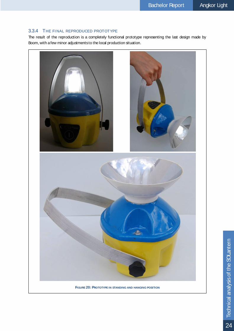
3.3.4 THE FINAL REPRODUC ED PROTOTYPE The result of the reproduction is a completely functional prototype representing the last design made by
Boom, with a few minor adjustments to the local production situation.
FIGURE 20: PRO TOTYPE IN STANDING AND HANGING POSITION

Bachelor Report Angkor Light
Tech
nica
l ana
lysi
s of
the
SOLa
nter
n
25
3.4 PROTOTYPE TESTI NG In order to see if the product fulfils its requirements certain tests need to be performed. Each test is preceded
by a description of the purpose and an evaluation at the and with any problems discovered.
3.4.1 USER TEST A very simple user test with the prototype of
Boom has been done, therefore only basic
information about the lantern at this stage is
known. The purpose for this test is to get more
insight into the thoughts of rural people about
the lantern in general, about how they are able to
use it and if they are capable and willing to pay
the estimated selling price.
The most important conclusions of the user test
are that the lamp is used by people as intended.
The function of the lantern with and without the
reflector is understood well and things people want to do with it are exactly the intended ones.
Disadvantages mentioned are the bad fixation of the reflector and the weight. Three out of ten people are
capable of and willing to pay the price of $50, but only if the quality of the product is very high and it will last
long. The other people want to buy the product for a price between $20 and $25, otherwise they cannot it.
The complete questionnaire including literal answers can be found in Appendix G .
3.4.2 WATER TEST During this test an amount of water with a pressure between 1 and 2
bar is being sprayed over the product at a downwards angle. Also
water from the side and from below is sprinkled, simulating rain
splashing on the floor. To determine if and where water is coming
into the lantern, paper tissues are placed against the casing and on
top of the inner parts. A complete test set-up can be found in
Appendix I .
Unfortunately water is leaking into the casing at the following
points:
The holes used by the connection bolts between the top
and the bottom casing
The holes used by the connection bolts between the
bottom casing and the handle
The little gap between the to ends of the rubber on top of
the bottom part
This means that water is coming through every possible hole in the product. The first two problems are very
similar; a solution can probably be found in the same direction.
FIGURE 22 : WATER TEST
FIGURE 21: USER TES T AT A FAMILY HO ME WITH THE PROTOTYPE

Bachelor Report Angkor Light
Tech
nica
l ana
lysi
s of
the
SOLa
nter
n
26
3.4.3 DROP TEST The requirement made by Boom concerning the height where the lantern could be dropped from was 50 cm.
This value was taken because almost every rural family has some combined tables/couches in their home,
which have an average height of the assumed criteria. Because a rural house always has a tamped down
earthen floor and this will also be the hardest kind of foundation during outside use of the lantern this kind of
surface was add to the criteria.
Results of the test are listed below, a complete report can be found in Appendix H .
A casing made of acrylic was very brittle and was damaged easily
PS and ABS have much better impact resistance; partly because they are more flexible
The damage mostly occurred at the point were the battery touched the casing. This was possible
because the upper casing and the frame did not fixate the bottom casing into its original shape during
the collision.
The frame including its connections did not suffer from multiple drops
PC, although not actually tested, will probably not be strong enough to withstand the same drop test
FIGURE 24: RESULT USING THE ACRYLIC CASING
FIGURE 23: DUMMY BATTERY AND PO LYSTYRENE CASING

Bachelor Report Angkor Light
Tech
nica
l ana
lysi
s of
the
SOLa
nter
n
27
3.5 COMPETITORS Several competing products are on the market, but most of them are not available in Cambodia. An extensive
examination of these products was performed by Stephen Boom including a comparison of the strengths and
weaknesses. One of the outputs of this research was a collage of the most important ones (Figure 25).
Most of these products have a cheap appearance, feel
cheap and are cheap. Some are of a much better quality,
are much more expensive and are made for the western
(camping) market. The cheap ones cost as less as $10,
the expensive ones have typical prices of $10 and more.
The characteristics of a stereotypical lantern are (Boom
2005):
A big plastic handle to carry the product
Top part with the on/off switch. This part can be
opened to replace the light bulb.
A cap to give the impression that the light
reflects downwards.
(Semi) transparent cap to cover the light bulb
inside. Mostly it makes use of fluorescent tubes
of 5-7W
A solid base for lead acid battery or dry cells and
electronics. The base can be opened to replace
battery.
An separate solar panel (if included)
Chinese products are famous in Cambodia because of their lack of quality. In accordance with this finding an
important conclusion was made about these competitors; to excel above their level a quality product with
according look and feel should be made. The new lantern should be able to distinguish itself on appearance
and functionality from these stereotypical models with a bad reputation. The risk of (illegal) copies by Chinese
manufacturers should be taken in account during the design of the lantern.
Because this investigation took place in 2005 the products currently available could be changed. Also a
comparison between these products and the existing Angkor Light is possible to reveal the current advantages
and disadvantages.
3.5.1 COMPARISON The biggest advantage of the Angkor Light is its light beam
shining more than the full lower (or upper) hemisphere
(Figure 26). All other products have a cap blocking light at
the top side, some of them also have bars to support this
cap prevent light to pass in some horizontal directions. The
other advantages not seen at any other product are the
ability to use a optional reflector to converge the light if
necessary and the possibility to turn and fixate the lantern
to aim downwards or forwards.
FIGURE 25: COLLA GE OF CO MPETITION (BOOM 2005)
FIGURE 26: THE LIGHT DISTRIBUTION AROUND THE
PRODUCT IN AN ANGLE OF 110 DEGREES MEASURED
FROM THE VERTICAL AXIS (LOWER HEMISPHERE)
1m α=100 0

Bachelor Report Angkor Light
Tech
nica
l ana
lysi
s of
the
SOLa
nter
n
28
The most important advantages of competing lanterns are:
One product featured an extra connection to charge mobile phones or other small devices
Some lanterns are very light weighted
The size of some lanterns is very small
If possible these features should be incorporated into the new design.
3.6 STANDARDS Several standards were used to check and to show the quality of the product. Guaranteed quality is very
important in the Cambodian market situation, due to the existence of a lot of (Chinese) products of inferior
quality. Together with the existence of known selling points the trust of the consumer can be acquired.
3.6.1 INGRESS PROTEC TION RATE To satisfy the need of checking the level of being water proof the Ingress
Protection rate is used. The IP rating defined in international standard IEC 60529
and classifies the level of protection that electrical appliances provide against the
intrusion of solid objects or dust, accidental contact, and water. The one used is
IP23, standing for the protection against:
Objects of 12.5 mm and bigger (fingers or similar objects)
Water falling as a spray at any angle up to 60° from the vertical
(rainwater)
To determine if the product complies with this standard, tests need to be done.
3.6.2 PVGAP AND IEC PV GAP (Global Approval Program for Photovoltaics) is a not-for-profit international organization, dedicated to
the sustained growth of global photovoltaics (PV) markets to meet energy needs world-wide in an
environmentally sound manner. Its mission is to promote and encourage the use of internationally accepted
standards, quality management processes and organizational training in the design, fabrication, installation,
sales and services of PV systems. To this end, it partners with PV related industries, international organizations,
testing laboratories, government agencies, financing institutions, non-governmental organizations, and private
foundations, in developing and developed countries.
FIGURE 29: EXTRA CONNECTION
FOR POWER OUTPUT
FIGURE 29: VERY SMALL AND
LIGHT WEIGHTED
FIGURE 29: TYPICAL COMPETING
SOLAR LANTERN
FIGURE 30: THE PV
GAP MARK

Bachelor Report Angkor Light
Tech
nica
l ana
lysi
s of
the
SOLa
nter
n
29
PV GAP co-operates closely with the International Electrotechnical Commission (IEC) in respect of
standardization (principally with IEC Technical Committee N° 82, Solar Photovoltaic Energy Systems) and
certification (with the IEC Quality Assessment System for Electronic Components, IECQ).
By obtaining a PV GAP mark the product can be distinguished from the bad Chinese product available on the
market. The standard consists of several documents called PV Gap Standard Specifications, covering product
specifications for the both the electronics and the general design (PV GAP, 2004).
3.7 CHANGED BOU NDARY CONDITIONS Several additions to the lantern have been requested by Kamworks due to problems encountered during the
design of the electronics. Implications will be described during the design phase. The alternations are new
boundary conditions for the redesigned lantern and consist of:
A bigger battery with more capacity, 4.5Ah instead of 3Ah
A CFL with separate ballast
Different electronics

Bachelor Report Angkor Light
Tech
nica
l ana
lysi
s of
the
SOLa
nter
n
30
3.8 LIST OF REQUIREMENTS OF THE ANGKOR LIGHT During the previous design stage performed by Stephen Boom a list of requirements was formulated (Boom,
2005). A lot of these requirements are in line with the findings presented in this chapter. The list is extended
with the changed boundary conditions and requirements from the company. A direct reference is added if
available.
3.8.1 PRODUC TION Vacuum forming should be used as production technology for the plastic parts
Final assembly should be in Cambodia
3.8.2 AESTHETIC S The product should have a modern western look and feel (Boom 2005, 2.3.3.1)
The product style should fit with the mood board made by Stephen Boom (Boom 2005, 3.6.3), the
colours should be bright and powerful the Cambodian way (Appendix P )
The product should express stability (Boom 2005, 2.2.3.1)
Make people feel proud to own a product like this; Refer to the Cambodian look and feel
The product should have a quality appeal and consist of plastic parts
The product should look and feel robust
3.8.3 THE PRODUC T SHOULD MEET THE DEMANDS OF THE PV-GAP The on/off switch should withstand cycle of 100000 times
Charge controller protect from damage from voltage under open circuit conditions
Protected against damage from reversal polarity conditions of battery and solar panel
The battery should be protected by a fuse. This may be on the circuit board
Solar panel connection should withstand minimum of 1000 connection cycles
The battery capacity (C2) shall not decrease over the testing period more than 10% of the initial
battery capacity. C0-C2/ C0 <10%
The measured days of autonomy shall match or exceed the defined minimum days of autonomy as
indicated by the manufacturer
The lamp shall operate undamaged according to the manufacturer specs. At maximum battery volt
and max radiation
The manufacturer shall specify the daily number of hours the system can service the load under test
conditions
The product should be able to operate during rainy conditions a according to IP23
The product should be able to withstand the shipping vibration test
3.8.4 ELEC TRIC AL C OMPONENTS
L I G H T
The light bulb should be visible
The light bulb should be able to be replaced
The CFL should meet the PV-GAP standard
B A T T E R Y
The battery should not make contact with the electric system when stored
The battery should have a minimum capacity of 2,5 Ah (at 12V)
After purchase, a fully charged battery should be able to operate the product 3 hours without being
recharged in between (Boom 2005, 3.5.4)

Bachelor Report Angkor Light
Tech
nica
l ana
lysi
s of
the
SOLa
nter
n
31
The battery should be protected from direct sunlight
The user should be able to obtain information when the battery is almost empty
The user should be able to obtain information about the charging status of the product
The battery should be able to be replaced
The battery should meet the PV-GAP standard
S O L A R P A NE L
The panel should be able to take inside the house (Boom 2005, 2.2.3.3)
The panel should be able to be fixated and aimed at the sun
The product should operate on 12 Volts (Boom 2005, 3.4.1)
The panel should meet the PV-GAP standard
3.8.5 OTHER The selling price should not exceed the maximum of $50
The product should be sold as one integrated package containing the solar panel determined in
(Boom 2005, 3.4.4), mobile lighting unit and instruction guides
3.8.6 USE The product should be able to be carried by the user (Boom 2005, 3.3.2)
The lighting product should be able to stand on a rough underground like stones and sand and mud
(Boom 2005, 3.3.2)
The lighting product should be able to be hanged (Boom 2005, 2.2.3.1 and 3.3.2)
The light should shine evenly distributed in an angle of 110 degrees measured from the vertical axis,
around the product
The minimum illumination level should be at least 20 lux at a distance of 1m
Components that are irreplaceable, like casing and frame, should be able to operate after a fall of 50
cm (walking height and table height) on earth ground (Boom 2005, 3.3.2)
3.8.7 L IST OF PREFERENC ES The product should made be out of local materials which are easy provided
The production of the product should fit with the main objective to contribute to the development of
Cambodia by offering local labour
Users can easily take the lantern and solar panel to their work (rice field or marketplace)
The product should be easy to repair
The product should fit all lighting categories
The product should have a connection to supply power to other products (e.g. a mobile phone)
3.9 DEFICI ENCIES OF THE PRODUCT After analyzing the recommendations, reproducing the prototype and performing a user, a drop and a water
test and comparing the results with the requirements several deficiencies of the product can be summarized.
Solutions to the problems to meet the requirements will result in the final product presented in chapter 4. The
following problems were found:
3.9.1 CASING The handle touches the top casing causing scratches
The knobs used to hold the handle into position are heavily clamped when the handle is turned and
damaging the casing (this happens because of the turning in combination with the screw thread)
One side of the base casing is weaker then the other parts (no frame is behind the plastic)

Bachelor Report Angkor Light
Tech
nica
l ana
lysi
s of
the
SOLa
nter
n
32
The casing is damaged due to the pressure performed by the internal frame during use
The casing is not watertight, especially at the separation between the two ends of the rubber and the
opening for the bolts connecting the top casing with the internal frame
The casing is not large enough to contain the bigger battery
3.9.2 ELEC TRONIC C OMPONENTS Users can easily open the product and access the electronics producing approximately 300V during
start-up of the CFL (Hil, 2007)
Users can easily access the electrodes of the battery and/or detach the battery itself to use it in other
ways, causing battery exhaustion and illegitimate warranty claims
Because the power connector is placed on the circuit board and because it has no supporting frame
behind it a lot of torque is applied every time a connector is plugged in. The circuit board might be
damaged after time
The lantern is designed for a CFL including a ballast instead of a CFL with separate ballast
No interface for the new electronics is available
3.9.3 PRODUC TION The edge of the painted and the transparent area of the top casing is frayed
The paint comes off at the contact points between the top casing and the base casing
3.9.4 AESTHETIC S The picture of the on/off button is not exactly placed above the button itself
When the on/off switch is pushed it sometimes does not work because of the stiffness of the plastic
in front
The on/off switch works unnaturally: in an outward position the lantern is turned on, in an inwards
position it is turned off
The light of the lamp shines through the lower casing, revealing the threads and other inner parts
giving the product an shabby look
The colours chosen in the prototype do not reflect the taste of the Cambodian population
3.9.5 COSTS The price of $62.71 (see Table 2) is much higher than the target price of $50
3.9.6 OTHER PROBLEMS When the lantern is placed at an downward angle the lantern is not balanced
The handle is cutting into the users hand, especially when the lantern is placed at an downward angle
Because there are 4 stability pins at the base casing it is overdetermined and not stable at a bumpy
surface
The reflector does not stay in position when aimed to the front neither turned when aimed
backwards
3.10 CONCLUSIONS During the tests and the analysis done with the prototype several deficiencies were found. To fulfil the
requirements described in §0 several adjustments to the design, the production process need to be carried
out.
Elements that make the Angkor Light unique should work properly; extra attention should be given to these
elements in the design process of the final product. Also the cost price need to be more specific and should be
reduced to make the product affordable for the target group.

Bachelor Report Angkor Light
Des
ign
of th
e A
ngko
r Li
ght
33
FIGURE 33: OVERVIEW OF THE ANGKOR LIGHT
4 DESIGN OF THE ANGKOR LIGHT
4.1 INTRODUCTION The previous chapter dealt with several shortcomings of the current product. In the following chapter the
solutions to these problems will be presented. Changes to several parts are summarized first followed by
solutions to general problems. At last a total cost price calculation is given.
4.2 GENERAL PRODUCT LAYOUT The products consists of a internal frame wrapping around the battery and serving as a support for the casing
and other components. The following order will be used
in this chapter (see also Figure 33):
Casing
o Reflector
o Top casing
o Inner top casing
o Base casing
Handle
Front plate
Internal components
o Internal frame
o Light source
o Electronics
FIGURE 32: SOLANTERN
FIGURE 31: ANGKO R LIGHT

Bachelor Report Angkor Light
Des
ign
of th
e A
ngko
r Li
ght
34
4.3 REFLECTOR 4.3.1 REFLEC TIVE LAYER The material chosen by Boom consists of a plastic PS sheet with a very thin reflective layer glued on top of it.
As seen in the previous chapter cracks develop very easy and make this material not really applicable. Gluing a
thin reflective layer on top of a plastic sheet will also cause problems; tests revealed that vacuum forming is
not possible because the layer is to stiff and will not form when it is glued onto the product afterwards seams
will always be visible because it does not shape very well into double curved surfaces.
Some different brands of reflective paint are
available in the neighbourhood of Phnom Penh;
two types of spraying paint and one type of paint in
a can were found. The chrome spray has much
better reflective properties than the other ones;
even better than the original reflective layer (see
Table 3 for the test results). To prevent the layer
from scratches an extra layer of clear paint was
added, unfortunately decreasing the extend of
reflection with about 40 lux.
Because of the much longer lifetime of the reflector the choice was made to add the clear paint nevertheless.
4.3.2 F IXATION The reflector does not stay in position
when placed forwards or backwards. It
even falls off when the lantern is turned
downwards. This problem is caused by
the shape of the reflector and the base
casing which are modelled to be able to
be released by the mould. The current
solution with two rubber strips does not
provide enough friction to fixate the
reflector.
The reflector must also be able to be placed at the base casing upwards and downwards causing more
problems because the connection point of the reflector has a draft and is therefore not symmetrical in de
vertical direction. Several options were drafted and tested on usability and makability. The solution chosen
consists of a click mechanism with a rim making use of the flexibility of the plastic (Figure 34).
4.3.3 REMOVING OF THE REFLEC TOR By adding a click mechanism to fixate the reflector the force needed to
detach it will be higher. Removing the reflector without adjustments is
difficult; therefore an extra rim was created (Figure 35). The rim is easy to
release from the mould and formed in a regular shape, making the mould not
more difficult to produce.
FIGURE 34: REFLECTO R FIXATION PROBLEM
AND SOLUTION
Reflector colour Illumination (lux at 1m)
Without reflector 20.2 White plastic (abs) 70.4 Bright silver (spray) 76.5 Silver (can) 148.8 Mirror film 163.5 Chrome (spray) 216.0
TABLE 3: REFLECTOR COATING ILLUMINATION
FIGURE 35: RIM TO REMO VE
THE REFLECTOR

Bachelor Report Angkor Light
Des
ign
of th
e A
ngko
r Li
ght
35
4.4 TOP CASING The addition of the rim to the reflector also implies changes to the top casing
(Figure 34). The solution chosen for this part has four separate horizontal rims
instead of one big horizontal ring, because this fits better into the design of the
existing vertical grooves. Tests with the prototype showed both a complete ring
and separate rims provide a good solution to the fixating problem.
Another design consideration was the possibility to use a cavity to lower the
screws attaching the upper parts onto the frame (Figure 36). Lowering the
screws is optically better, but two big problems were encountered. The first
problem was the connection to the internal frame. The cavity is rounded at the bottom side due to problems
occurring during vacuum forming while using sharp
corners. The rubber ring between the internal frame and
the casing had to be shaped according to the cavity; this
was not possible using the available material and tools.
The second problem was the precision required to position
the top casing into the inner top casing. In theory the
depth of a cavity can be at most 75% of the width of the
opening on the surface, excess thinning will occur beyond
this depth (Formech International Ltd., 2001). Even shallow
cavities will result into a thinner casing, especially at these
two points where the top casing connects to the frame this
is very unwanted.
The shape of the top casing was altered to make it visually
more consistent with the lower part. Making the top casing
rounder also has several advantages:
The chill marks encountered during the production of the prototype will be minimized because the
plastic is stretched less at the top (see §3.3.3.1)
The total shape resembles Angkor Wat better, making it more recognisable as a Cambodian product
The top of the part will be stronger because there will be less stretching of the plastic making it less
thin
4.5 INNER TOP CASING One problem discovered after the production of the
prototype was that the light of the CFL shines trough the
base casing revealing a lot of the inner parts. This effect is
unwanted because it looks very cheap.
Two more problems encountered were the frayed
painting of the top casing and the paint coming off at the
contact points with the base casing. Several test where
done to obtain a straight paint line, like using paper tape,
a removable plug and even some fluids preventing the
paint to stick to the plastic. No solution was found
making it both possible to produce the product locally
and being also a solution usable in a production process.
FIGURE 36: CAVITY
FIGURE 38: INNER TO P CASING
FIGURE 37: TOP CASING

Bachelor Report Angkor Light
Des
ign
of th
e A
ngko
r Li
ght
36
All problems can be solved by using a separate part.
This extra layer blocks the light normally shining
through the base casing and is used to colour the
lantern.
The part can also be painted by artists to make a
special collectors item or can be decorated with
stickers. The extra costs to produce this part are
partially by the lack of a layer of paint and the added
quality appeal to the lantern.
4.6 BASE CASING The total shape is adjusted to the bigger battery which is
about 1.5 times higher than the old one and has
therefore been rotated 90° to lower the point of gravity
and make the lantern more stable. Still it has effect on
the height and the required strength of the base casing
because of the increased overall weight and volume. The
drop tests described in §3.4.3 revealed that PS with a
thickness of 1.5 mm was needed, instead of 1 mm in the
original design. Vacuum forming test with this material
showed that sharp corners and deep cavities could cause
problems.
The new design was adjusted to fit the Cambodian style
together with the top casing. More curves are used
compared to the SOLantern, this was possible because
the frame was used to position the battery instead of the
casing itself. Rounded corners also facilitate the vacuum
forming process and these curves make it less obvious
that it is a casing for the rectangular battery. The
indentations were kept because they strengthen the
casing, identify the front panel and reflect the shape of
the top casing.
The number of stability pins has been decreased from
four to three, making the connection with the ground not
overdetermined anymore. These pins are placed as far as
possible to the outside of the product to provide as much
stability as possible. Drafts to ease the release of the part
from the mould were missing in the original design and
were added.
The battery support nodes were kept to absorb the
energy of the battery in case the lantern will be dropped
onto the ground.
FIGURE 40: BASE CASING WITH HOLES FOR
CONNECTIONS
FIGURE 41: BOTTOM LAYOUT WITH STABILITY PINS
AND BATTERY SUPPO RT NODES
FIGURE 39: EXAMPLE OF A DESIGN

Bachelor Report Angkor Light
Des
ign
of th
e A
ngko
r Li
ght
37
4.7 HANDLE 4.7.1 HANDLE FIXATION The handle needs to be turned into a certain direction and must be
able to be fixated in that position. Heavy clamping of the casing has to
be prevented when the handle is turned (see §3.9.1).
Several concepts have been developed to eliminate this problem, all
with several advantages and disadvantages. The main considerations
are to ability to produce it locally and the expected lifespan. By limiting
the rotation to a certain degrees the problem arises that not all
lightning function can be fulfilled. After testing of several possibilities
the most basic one turned out to be the best: a rubber ring made of an
old car tire will fixate the handle in every desirable position without
damaging the casing (Figure 42). This material is also very cheap and
easy available in rings.
A nut is welded onto the internal frame to provide screw thread for the bolt attached to the knob. A rubber
ring is also placed at the inner side of the casing to prevent harmful contact between the internal frame and
the plastic casing (and also to make the lantern waterproof).
4.8 INTERNAL FRAME The internal frame is made of steel and is more capable of resisting shocks than plastic. Therefore the support
function of the casing for the heavy battery was decreased by transferring it to the frame. To achieve this, the
frame was almost completely released from
the base casing and rubber rings were placed
in between to absorb the energy transferred
from the frame to the casing. Only the bottom
part of the frame is still slightly connected due
to height restrictions.
By adding a frame at the back the casing is
stronger in general and the back of the
product is also supported. Only little weight is
added by this alteration.
The nuts to attach the frame were
repositioned to the height of the point of
gravity to balance the lantern. These are
welded onto the frame to achieve a solid
connection. By unscrewing the knobs of the
handle little adjustments of the rotation can
be made very easy and the lantern is not
tumbling any more.
The frame can be separated into two parts by
unscrewing four bolts making it possible to
FIGURE 42: FIXATION KNOB
FIGURE 43: EXPLO DED VIEW OF INTERNA L FRAME

Bachelor Report Angkor Light
Des
ign
of th
e A
ngko
r Li
ght
38
change the battery. Each part consists of two strips welded together (after being bended). Two strips are
added to the top part to support the CFL holder.
4.9 ELECTRONICS Simultaneously with the development of the Angkor Light new electronics were designed by two students of
the “Haagse Hogeschool”. The goal of this project was (among others) to design an external ballast having
several advantages over a commonly used internal ballast:
The external ballast developed is able to dim the CFL
The ballast will be separate of the CFL giving more design opportunities
The ballast designed will be more power efficient
Beside the development of this ballast a new controller for the CFL and a charge controller for the battery type
used were designed making the lightning and loading much more efficient.
4.9.1 CFL By quantifying the lighting categories in which the lantern need
to be used the sufficiency of the light output of the final product
can be checked. These values stated in Table 4 are based on the
recommendation of Duco Schreuder (Schreuder, 2005) on
lighting for very poor people.
Type of light Illumination level Orientation light >10 lux General light. >20 lux Task light >30 lux Spot light >50 lux
TABLE 4: ILLUMINATION LEVELS BY (SCHREUDER, 2005) AS FOUND IN
(BOOM, 2005)
FIGURE 45: COMPLETE INTERNAL FRA ME
FIGURE 44: BALLAS T OF A NORMAL CFL
FIGURE 46: LIGHT DIS TRIBUTION OF 3W CFL
LAMP (KAMWO RKS, 2007)
25 lx at 1m 20 lx;
at 1m
12 lx; 1m Z

Bachelor Report Angkor Light
Des
ign
of th
e A
ngko
r Li
ght
39
A 3W CFL has a light distribution of at least 20 lux in the horizontal direction measured at a distance of 1m
(Figure 45) and is very energy efficient. The alternative, an array of led lights, is not as efficient as a CFL and its
light distribution characteristics are far less suitable for general lightning purposes. A led with a capacity of
about 10W is needed to match a 3W CFL (Boom, 2005).
Because the light intensity at the top side of the CFL does not fulfil the requirement of 20 lux for general light
instead of the 3W variant a 5W CFL has been chosen. This CFL has an intensity of 20 lx at 1m (see Appendix J
for light measurements tests).The costs for a 3W or 5W CFL are almost the same and by using the electronics
dimming of the light will be possible when the extra light output is not needed.
FIGURE 48: CFL WITH AND WITHOUT BALLAST
FIGURE 47: CFL AND HOLDER

Bachelor Report Angkor Light
Des
ign
of th
e A
ngko
r Li
ght
40
4.9.2 CONNEC TION FOR EXTERNAL DEVICE A big advantage of one competitive product was the ability to connect an external
device to the battery (see §3.5.1). This can be very useful for charging mobile
phones or powering a small radio. The electronic controller already supported
power output control preventing the battery from being discharged too much.
This new function can therefore easily be integrated in the existing system. The
connection also reduces the risk of people opening the casing to connect a device
to the battery directly.
The connector chosen is a 2.5 mm phone jack, normally not associated with
power output. The intention with this choice was to prevent people from plugging
in external devices without knowledge about the possibilities of the lantern. Only after consultation of the
vendor a very cheap converter switch can be bought. This method is necessary because of the very limited
knowledge of electrical devices of rural people.
4.9.3 L IGHT INTENSITY BUTTONS AND LED INDIC ATORS Due to the extra function to dim the CFL some extra buttons had to be added. LEDs are used to indicate the
state of charge of the battery and to indicate if the solar panel is connected correctly. In the ideal situation this
will be indicated by to separate LEDs, but unfortunately this is not possible because of the shortage of
connections on the microcontroller as a result of the extra light intensity buttons. The microcontroller has 14
connections, which are used in the ways explained in Table 5.
A choice had to be made between the use of:
1. A set of extra buttons to adjust the light intensity and one LED indicator
2. A single power/light intensity button and two LED indicators
The first option was chosen because the use of one button as power switch and light intensity regulator is
confusing to the user (this effect was seen during tests with competitive products using this method). To
combine the battery state and the indication of the correct connection of the solar panel into one indicator the
scheme defined in Figure 50 will be used.
A blink will be 0.5 seconds long, making the indication of the almost empty state (0-5%) a continuously blinking
process. To get some extra attention from the user when the battery reaches this state the CFL will also be
flickering every second for a period of 5 seconds, making it very clear that there will be no more light in about
10 minutes.
F IGURE 50: BATTER Y STATE WITH LED
INDICATION TYP E
F IGURE 49: PHONE JACK
Nr. Connection 1. Battery current 2. Pulse-width modulation for buck converter (CFL
control) 3. Solar panel current 4. Dim switch + 5. Dim switch - 6. CFL control 7. CFL control 8. External connection 9. Fault detection CFL 10. Wake-up after connection of panel or external
connection 11. LED 12. On/Off switch 13. Power supply + 14. Power supply -
TABLE 5: M ICROCONTROLLER CONNECTIONS

Bachelor Report Angkor Light
Des
ign
of th
e A
ngko
r Li
ght
41
4.10 FRONT PLATE The front plate is the most important part for the user interaction with the lantern. It must at least contain an
on-off button and a solar panel connector. Another requirement i that it has to be waterproof; especially the
connector(s) and the buttons are a point of attention because they are used a lot and pressure is applied to it.
4.10.1 LAYOUT Due to the extra connection and the extra buttons the
design of the front plate had to be redesigned and
several new considerations had to be made.
Not all domestic appliances are suitable to be connected
via the external output, e.g. a television could
impossibly run on this kind of battery. The connector of
the solar panel may also not be put in the output. Clear
marking of the input and the output connectors will be
the best solution, but a shortage of space arose from
the addition of all the new part leaving no room for
clear icons.
The position of the connectors is considerably
influenced by the position of the internal frame. The
frame is positioned vertically in the middle of the front
plate and the connectors cannot be put in front of it without drilling holes and weakening the frame.
Repositioning the frame was no option, therefore the connectors had to be placed at the side of the front
plate. By using two different connectors it will be completely prevented that users will choose the wrong
connector by mistake.
Due to this extra output connector a new hole must me made in the front plate. To control the light intensity
two more buttons were added, causing the total button count to rise to three. In the original design the
connector was a separate part and not connected to the front plate directly but mounted on the circuit board.
Both connectors are mounted onto the front plate using a screw to make a waterproof connection.
4.10.2 MEMBRANE SWITC H A big difference with the SOLantern is the type of buttons used.
Instead of a micro switch mounted unto the circuit board a
membrane switch is used. The big advantages of this kind of
button are its very small size, the ability to integrate it into the
front cover, its durability and the clustering of all connection
threads into one strip. Only one hole for this strip has to be
made into the casing and because it is positioned in the centre
of the cover it will be completely protected from water. Another
problem solved with this kind of button is the absence of torque
performed on the circuit board when the button is pressed. Also
the placement of the picture of the button will be exactly on top
of the button itself.
FIGURE 52: MEMBRANE SWITCH CO MPOSITION
FIGURE 51: FRO NT COVER WITH CO NNECTIONS

Bachelor Report Angkor Light
Des
ign
of th
e A
ngko
r Li
ght
42
4.11 MECHANICAL CONNECTIONS 4.11.1 PREVENTING AC C ESS TO THE INNER PARTS Touching the inner parts is potentially dangerous because of the high current used to start the CFL. In
Cambodia the “creative” use of products is very common, e.g. using the battery for other purposes without the
power regulating electronics. A warranty is given by Kamworks so any undesirable use causing a broken
battery should be minimized. Access to the inner parts has to be restricted to end users but not to repair
mechanics.
Sealing of one or more parts with for example plastic sheet will
solve the problem partially. The biggest problem is the
connection of the CFL and the wiring to it from the electronics
through which a voltage of about 300V will run when starting up
the lamp for a short period (Hil, 2007). Another point of
attention is the potential access to the connection from the
battery to the electronics. These electronics prevent the battery
from being charged or discharged too much, but nothing should
interfere with them to make this work.
Because it is not necessary for end users to access any internal part these can be sealed using the casing. A
screw that can not (easily) be removed will be a good solution to this, e.g. a Torx screw (Figure 52). The
drawback of this seal is that end users will not be able to replace the CFL themselves. With a life expectancy of
3 years the replacement of the CFL by a Kamworks entrepreneur will be sufficient.
4.11.2 MAKING THE INSIDE WATERPROOF To solve the problems discovered during the water test multiple alterations to the design were made.
Rubber rings were placed around the screws and between the internal frame and casing, preventing water to
enter through the holes.
The front panel was replaced by a membrane switch, covering the hole
necessary for the wires to the on/of switch. Jacks with screws are used to
create a watertight connection. Rubber rings can be used as a seal if
necessary.
Finally silicone kit is used instead of a rubber hose to fill the gap between the
base and upper casing. Silicone kit is more elastic and extra material can be
applied in corners to follow the shape of the casing more accurate.
4.12 ELECTRICAL CONNECTIONS The charge and output controller are mounted on the same circuit board making the wiring easier (Figure 56).
The arrows in this figure represent physical wires between the components and are implemented in the
following ways:
The wire attached to the solar panel is connected to the circuit board
with a DC power plug and a normal DC power jack (Figure 53). This
jack is connected by welds on the circuit board and small crimp
terminals at the side of the power jack (Figure 54)
The connection between the battery and the circuit board is made
by a wire weld to the circuit board and crimp terminals at the battery
side
FIGURE 53: TORX SCREWS
FIGURE 55: CRIMP TERMINALS
FIGURE 54: DC POWER JACK
WITH SCREW

Bachelor Report Angkor Light
Des
ign
of th
e A
ngko
r Li
ght
43
The same wire is used to connect the battery with the output controller
The wire to the CFL holder is welded onto the circuit board and screwed
into the holder
Small crimp terminals are used to connect a wire to the jack for the external
device. This wire is welded onto the circuit board
The wire from the user interface (front plate) is attached to the circuit
board by a plug and socket connector (Figure 56)
By using a permanent connection at one side and a releasable one at the other side all components can be
detached and replaced if necessary.
4.13 BATTERY The battery chosen by Kamworks is the Genisis NP 4.5-12. This
sealed lead-acid battery is has a current of 12V with a capacity of
4.5Ah.
The electronics developed prevent the battery to discharge more
than 50%. At this rate the battery has a life expectancy of about
550 cycles. This amount increases quickly when discharged less:
at a discharge depth of 30% the life expectancy rises to 1200
cycles. The expectation is that people will use the light for an
average of less than 4 hours a day, making the expected life span
of the battery about three years.
F IGURE 57: ELECTRONICS IN THE ANGKOR L IGHT
F IGURE 58: THE BATTERY USED
F IGURE 56: FLAT PLUG

Bachelor Report Angkor Light
Des
ign
of th
e A
ngko
r Li
ght
44
4.14 MATERIALS 4.14.1 PLASTIC S The materials possible for the plastic parts were tested using a drop test described in paragraph 3.4.3. Several
other considerations were made during the selection of the appropriate plastic for the Angkor Light. The
characteristics are summarized in Table 6. Several inquiries have been carried out to obtain the price for all
materials, which are summarized in Appendix D .
The choice for PS was made because of its low price, its easiness to vacuum form, its shiny surface look and
transparency. No other material has all these properties. The only real disadvantage found is its UV sensitivity.
The lantern will only be used at night, when it is kept away from the sun during day (and while charging the
battery) the problem can be avoided. The packaging should inform people about this potential problem.
The parts damaged (by sunlight) should be obtained very easy from the Kamworks store at a very low price.
Due to the low material costs and production costs this will be possible.
4.14.2 METALS The metal for the handle selected by Boom was galvanised steel. This material is hard to get in Cambodia, and
only as large sheets. A possibility is to the cut the sheets into strips width the desired width, but the tooling
costs would be very high. The borders are also very sensible for rust because they are not galvanised. An
alternative was found by use of aluminium instead. This material is light weighted, easy available in the right
size and has a quality appeal. The material costs are higher than the galvanised steel, but this is compensated
by the lack of extra tooling cost.
The internal frame is still made of galvanised steel, these strips are less thick and cutting is therefore much
easier.
Material Price per piece
(1.5x244x250mm) see Appendix D.2
Advantages
(Formech International Ltd., 2001) (Zeus Industrial Products, Inc., 2005)
Disadvantages
(Formech International Ltd., 2001) (Zeus Industrial Products, Inc., 2005)
PC $0.46 Very strong, not brittle Transparent and highly shiny Good resistance against weather influences
Expensive Hygroscopic
PS (or HIPS)
$0.18 Transparent, shiny surface look Cheap Easy to vacuum form
Does not withstand UV very well
ABS $0.21 Very shiny Strong material Easy to paint and glue
Not transparent
PMMA (Acrylic) $0.30 Highly transparent All colours available
Very brittle Difficult to vacuum form
PETG $0.28 Easy to vacuum form High transparency Good recyclable Stronger than acrylic
Expensive Bad UV resistance, not used for durable consumer goods
APET (Amorphous PET)
$0.35 Easier to vacuum form than PETG High transparency Good recyclable Stronger than acrylic
Expensive Bad UV resistance, not used for durable consumer goods
TABLE 6: PLASTIC CHARA CTERISTICS

Bachelor Report Angkor Light
Des
ign
of th
e A
ngko
r Li
ght
45
4.15 COLOURS During the basic user research of Stephen Boom several colour schemes were presented to the people. All
participants favour bright colours and like shiny materials (Figure 58). A possible explanation for this fact is
that most products available are not very coloured, not shiny and look cheap especially most Chinese
products. People want to show off with the lantern and want a real quality appeal.
All plastic parts can be made in a lot of bright colours because the availability of sheets is high. The front plate
however can be produced in one colour only. Very high start-up costs are required to produce them, only
when a second batch is ordered it can be changed. Dark red is chosen because of the contrast with the base
casing and because it matches best with all bright colours.
4.16 COST PRICE Getting a reliable forecast of the cost price of the
product and bringing it down was one of the most
important tasks of the assignment. A lot of things
were uncertain and based on rough estimations and
availability of parts in Europe.
A global part list was included in the report of
Stephen Boom (Boom, 2005), but it was not
containing all parts used. Also a lot of suppliers were
unknown. This list was used as a starting point and
extended with other all parts used for the product.
After the redesign of the lantern all items in the list
turned out to be replaced by new parts.
The costs of all parts used in the product have been
analysed. To obtain several possible distributors of
components and get different price indications,
many inquiries have been performed. Using these
inquiries an accurate estimation of the product price
could be made. The list with suppliers is also useful
Components Subtotal Total Plastic components $3,77 Electronics $9,94 Metal components $2,07 Screws, Nuts, bolds etc $2,05 Electronic parts $6,99 Solar panel $17,82 Subtotal $42,64 Transport $0,31 Packaging $1,50 Breakage $1,32 Subtotal $3,13 Marketing $1,42 Overhead $6,24 Profit $5,09 Subtotal $12,74 Margin retailer $6,50 Subtotal $6,50 Selling price $65,01
TABLE 7: THE COST BREAKDO WN OF THE FINAL PRODUCT
FIGURE 59: COLOUR CHOICE OUT OF THE USER TES T (BOOM, 2005)

Bachelor Report Angkor Light
Des
ign
of th
e A
ngko
r Li
ght
46
to decide which alternative can be chosen in case of a conflict with the current one or increased cost prices.
The total cost price breakdown including the complete part list can be found in Appendix E .
The total cost price (Table 7) marks the problem found during this process: the product price is $65, after
intensive research for cheap suppliers. The price per component chart (Table 8) reveals the share of each main
part of this total amount.
A big problem are the import taxes. The government collects about 10% VAT and 35% import tax. An
exemption is made for NGOs, but Kamworks is a commercial company and has to pay them. The price of the
solar panel is considered to be as low as possible after more than 25 inquiries. A comparison of the electronics
of several other distributors by the electrical engineering experts can possibly lower the price of the
electronics and the electronic parts (e.g. the battery). Margin for the retailer, overhead and profit are
determined by the Kamworks management, when the product is put into practice it can be seen if these values
are correct and reasonable.
TABLE 8: PRICE PER COMPONENT
$0,00
$5,00
$10,00
$15,00
$20,00

Bachelor Report Angkor Light
Des
ign
of th
e A
ngko
r Li
ght
47
4.17 PACKAGING Simultaneously with the redesign of the Angkor Light a
packaging concept was developed by Stefan Ruiter as
a bachelor assignment (Ruiter, 2007).
The packaging together with the manual provides
information about the product as defined in PVGap, it
protects the product during transportation and makes
clear what the product is used for and how when
placed in a market stall.
FIGURE 60: USER MANUA L (RUITER, 2007)
FIGURE 61: PACKAGING DESIGN (RUITER, 2007)

Bachelor Report Angkor Light
Des
ign
of th
e A
ngko
r Li
ght
48
4.18 THE FINAL PRODUC T The Angkor Light is the redesign of the SOLantern made by Stephen Boom. It is a solar lantern designed for the
rural population of Cambodia and is characterized by its sustainability, its suitability for multiple lightning
situations and low costs on the longer term. Possible reparations can be done by entrepreneurs educated by
Kamworks against very low repair costs. The lantern will be produced in Cambodia itself with as much
materials local available as possible.
FIGURE 62: EXPLO DED VIEW OF THE ANKOR LIGHT
FIGURE 63: ANGKO R LIGHT DURING OPERA TION

Bachelor Report Angkor Light
Des
ign
of th
e A
ngko
r Li
ght
49

Bachelor Report Angkor Light
Des
ign
of th
e A
ngko
r Li
ght
50
FIGURE 64: ANGKO R LIGHT IN HANGING POSITION

Bachelor Report Angkor Light
Prod
uctio
n
51
5 PRODUCTION
5.1 INTRODUCTION During the product development phase the production process was analysed. Some problems encountered are
used to redesign the product if possible, others are used to change the production process itself. This chapter
deals with all production analysis aspects not described in the previous chapters and the implementation of
the final product into a production environment suitable for Kamworks.
5.2 PRODUCTION SI TUATION Production in a third world country like Cambodia is completely different from a production situation in a
Western country. Educational standards are low, quality commodities are rare, the country is very corrupt and
the infrastructure is very bad. On the other hand it has a lot of advantages: labour costs are very low,
employees are easily available, the local community is much easier reached and last but not least Cambodians
are very patriotic and prefer “real” Cambodian products over foreign ones.
5.3 EMPLOYEES Kamworks currently has four employees capable of operate almost all available machines. Only the vacuum
forming machine is unknown to them, but it will be easy to operate because it will be programmed to perform
a complete production cycle by its own.
More employees can be hired easily if necessary because of the high unemployment rate in the country. An
educational level of grade 9 (comparable with 2nd class of the Dutch secondary school) will be a good starting
point for an internal training. The children at the orphanage will complete at least this grade, making it
possible for all of them to work at the company in theory.
Payment is a fraction of labour costs in Europe; good paid workshop workers earn about $80 a week. In
addition to the salary Kamworks also provides additional health and industrial disability insurance services
making them above-average employers.
A problem observed while making the prototype was the lack of accuracy of these employees now and then. In
Cambodia a lower quality standard (compared to western countries) is commonly used. This is not acceptable
while producing the Angkor Light in mass production. Checks for each critical part should be provided after
production as well as quality checks concerning the complete product performed at random.
5.4 PRODUCTION EQUIPMENT Several basic machines like the a drilling machine and a hand press brake are available (see Appendix C ). To
produce the Angkor Light some parts need to be made by a third party, e.g. the vacuum forming moulds. To
ease the production process some tools were designed, making the time required to produce a part lower and
the accuracy higher.

Bachelor Report Angkor Light
Prod
uctio
n
52
5.4.1 TOOL DESIGN The internal frame consists of a metal strip bend in angles of approximately
90°. The first consideration was to use dieing to shape the frame, but this
technique has several drawbacks:
A lot of dies are needed
The dies are expensive to make
Aligning the metal to the die is very difficult because the die pulls the
metal into its form making the metal slide easily
To verify if a die suites its purpose it has to be actually made. This
results in a high risk of losing the invested money if the die is
imperfect
The stroke of the available machine is not big enough contain the
frame (necessary for some bends)
An alternative bending tool was developed taking away all of these
disadvantages. All the corners have a ±90° angle, only the distance between
them varies so the tool has several positioning stops at the right distances. It
consists of locally available materials and is easy to manufacture. A hydraulic
cylinder can be attached to the handle to make it more productive (Figure 64).
A (rubber) stop can be used to stop the handle at the desired angle.
FIGURE 66: SECTION VIEW OF THE BENDING TOOL
FIGURE 65: TOP VIEW OF THE
BENDING TOOL
FIGURE 67: PRO TOTYPE OF THE BENDING TOOL

Bachelor Report Angkor Light
Prod
uctio
n
53
A bending tool was also constructed to get the right shape into the handle. Aluminium is pretty easy to bend, making it possible to do this by hand. The strip is fixated onto the tool using the hole used for hanging the lantern. To form the material a metal cylinder is used, possibly coated with rubber to prevent scratches. The aluminium strip can be turned 180° to make a symmetrical shape. This tool is also operated by hand and is therefore using no electricity.
To fixate the plastic parts during the drilling of the holes several supports were designed and tested. A frame
made of Fiberglas and epoxy built upon a metal construction turned out to be the most accurate and strong
solution. The metal construction was used to attach the support to the column drill. Only a metal frame did
not work because the frame could not be shaped correctly due to the double curved shape of the casings.
5.5 MOULD DESIGN Several considerations were taken into account during the design process to ease
the vacuum forming of the plastic parts. The new material thickness was
implemented and tested to reveal (potential) problems.
The changes in the design of the lantern considering the vacuum forming process
consisted of adding drafts to all vertical faces to ease the release of the parts
(Figure 69). New ideas like the click mechanism to fixate the reflector were tested
using prototypes (see Figure 70 and Figure 71).
Vent holes were added to aid the plastic shaping process. These holes are placed
in cavities and places where the material touches the mould last. The ideal
situation would be a mould where the plastic would hit the mould everywhere at
the exact time. To approach this situation the material is pre-formed using a
blower, the amount of seconds required was tested and written down to apply in
the production process. By adjusting this pre-bubble face the timing and wanted
material thickness can be tweaked.
FIGURE 70: DRAFT ADDED
FIGURE 69: BENDING TOOL SIDE
FIGURE 68: BENDING TOOL PERSPECTIVE

Bachelor Report Angkor Light
Prod
uctio
n
54
FIGURE 75: MOULD OF THE REFLECTOR (EXPLODED VIEW)
FIGURE 72: INSERTS TO MAKE THE CLICK
MECHANISM (EXPLODED VIEW)
FIGURE 73: MOULD OF THE BASE CASING
FIGURE 74: COMPLETE MOULD OF THE TO P CASING
FIGURE 71: PRO TOTYPE OF THE NEW CLICK
MECHANISM

Bachelor Report Angkor Light
Prod
uctio
n
55
5.6 PRODUCTION PROCESS 5.6.1 ENERGY C ONSUMPTION AND SUPPLY The power needed for production is produced by the
existing solar panels and an additional generator. During
the prototype production the values were gathered to
obtain an insight in the production situation.
The batteries of the solar system have a capacity of 19.2
kWh, the generator is capable of producing an extra 15
kWh. The vacuum form machine needs about 4.73 kW
for heating and another 0.75 kW for all other operations.
All other machines are using only a fraction of this
amount.
All costs required for the operation of these machines
have been used to calculate the final product price.
5.6.2 PLASTIC PARTS Production of the plastic parts consists of vacuum forming and finishing. The vacuum forming step takes place
using the moulds designed and the vacuum forming machine available.
To remove the waste material and obtain a nice upper edge several some finishing need to be done. To
investigate the local possibilities the following tools were tested:
Knives (hot or cold) are working but it takes a lot of time. Hot knives are a little bit faster.
A hot wire separates the plastic but also melts it together again
An angle grinder is much faster then a knife because it melts and removes the plastic in the grinding
process but is less accurate then previous methods
A hand saw is working but it costs a lot of human power
A figure saw is very suitable but an often occurring problem is that the product is too big to fit into
the machine
The conclusion was that saws with fine tooth are in general the best solution to separate the product and the
waste material. To make a smooth upper edge a simple knife can be used to scratch the burs off. To apply this
method to mass production a band saw is most useful, these machines are not very expensive and are
available in Phnom Penh.
The holes needed are made with a column drill. Several options to
fixate the parts were investigated; the problem encountered was
the many double curved surfaces. By making epoxy moulds
described earlier the exact internal shape of the parts could be
reproduced. The plastic parts can be places on the moulds very easy
and the placement is accurate.
Cutting the hole of the inner top casing will be done using a die. Because of the round shape of the die it can
be made pretty easy, while corners are difficult to produce (see Figure 76). An epoxy mould will be used to
position the part.
FIGURE 76: KAMWORKS SOLAR SYS TEM
FIGURE 77: INNER TOP FRAME CUT SHAPE

Bachelor Report Angkor Light
Prod
uctio
n
56
5.7 METAL PARTS 5.7.1 CUTTING The internal frame consists of metal strips with a width of 20 mm and varying length. Only metal sheet is local
available making cutting it to the correct size necessary. The guillotine shears in the Kamworks workshop are
only suitable to cut sheet in 90° angles or into vary small pieces. Sawing by hand is not possible because of the
necessary tolerances; machined sawing or cutting is not possible because no such machines are available at
the workshop and buying them would be to expensive. An external company capable of machined cutting was
found in Phnom Penh, the only drawback of outsourcing the cutting is the slightly higher cost but the quality is
much higher. The last option mentioned is used.
Aluminium for the handle was found with the right width as described earlier, cutting it into the right lengths is
done with a hand saw. Rounding the edges can be done with a sanding machine or a grindstone (both
available). Quality checks will be done using a template of the curves.
5.7.2 BENDING Bending is done by the tool design. Because the hole on the top side is used to fixate the part it should
therefore be drilled first.
5.7.3 DRILLING In contradiction to the hole used for hanging the holes for the knobs to attach the handle onto the internal
frame will be drilled after the bending process. This is done to make sure that they are made at the right
positions.

Bachelor Report Angkor Light
Prod
uctio
n
57
5.8 PRODUCTION GUIDE All actions needed to produce a part are summarized in the following pages. The assembly of parts that cannot be parted are also described in this section, e.g. connections by welding. 5.8.1 INTERNAL FRAME – LOWER PART
F R O NT -T O -B A C K A ND S I D E-T O -S I D E F R A M E 1. Cut a metal strip of 1.5mm thick galvanised steel to the desired length
2. Drill the holes using a drilling template
3. Bend the frame using the bending tool into the right shape
4. Check the precision of the frame using a reference template
B O T H 5. Place both parts in the welding template and weld them together
6. Remove wired edges if necessary
+ =
FIGURE 78: INTERNAL FRAME –LOWER PA RT
5.8.2 INTERNAL FRAME – UPPER PART
F R O NT -T O -B A C K A ND S I D E-T O -S I D E F R A M E
1. Cut a metal strip of 1.5mm thick galvanised steel to the desired length
2. Drill the holes using a drilling template
3. Check the precision of the frame using a reference template
B O T H 1. Place both parts in the welding template and weld them together
2. Remove wired edges if necessary
+ = FIGURE 79: INTERNAL FRAME – UPPER PART

Bachelor Report Angkor Light
Prod
uctio
n
58
5.8.3 TOP C ASING , INNER TOP CASING AND BASE C ASING
1. Vacuum form the casing with a 250x250mm PS sheet with the following thickness:
Top casing and base casing: 1.5mm
Inner top casing: 0.5mm
2. Remove the rest material
3. Drill the holes using the supports
FIGURE 80: TO P CASING FIGURE 81: BASE CASING
FIGURE 82: INNER TO P CASING
5.8.4 HANDLE
1. Cut a metal strip of 2mm thick aluminium to the desired length
2. Round the edges
3. Check the precision of the edges using a reference template
4. Drill the holes
5. Bend the frame using the bending tool into the right shape
6. Check the precision of the frame using a reference template
FIGURE 83: HANDLE

Bachelor Report Angkor Light
Prod
uctio
n
59
5.8.5 REFLEC TOR
1. Vacuum form the reflector with a 1.5x250x250mm PS sheet
2. Remove the rest material
3. Place the reflector in the paint support and paint a chrome
layer
4. Place the reflector in the drying cabinet
5. After drying: place the reflector in the paint support and
paint a transparent layer
6. Place the reflector in the drying cabinet
5.9 ASSEMBLY After production of the different parts required assembling them is the next step. The assembly has been
broken down into several sub-assemblies, making it possible to complete one part at a time. The process can
be managed and optimized according to work capacity and possibilities. The complete assembly process can
be seen in Figure 84.
FIGURE 85: ANGKO R LIGHT ASSEMBLY CHART
FIGURE 84: REFLECTO R

Bachelor Report Angkor Light
Conc
lusi
ons
and
reco
mm
enda
tions
60
6 CONCLUSIONS AND RECOMMENDATIONS
6.1 MEETING THE REQUIREMENTS After te redesign it has to be checked if the requirements defined at the beginning are met. Colour codes are
used to mark in which level the requirement is met in the following way:
Green mains = requirement met
Orange = partially met / not checked yet
Red = not met
When a requirement is partially or not met an explanation is given, with recommendations to meet it in the
future. Also ways to determine how requirements that are not checked yet can be verified will be given in the
recommendations section.
6.1.1 PRODUC TION Vacuum forming should be used as production technology for the plastic parts
Final assembly should be in Cambodia
6.1.2 AESTHETIC S The product should have a modern western look and feel
The product style should fit with the mood board made by Stephen Boom the colours should be
bright and powerful the Cambodian way
The product should express stability
Make people feel proud to own a product like this; Refer to the Cambodian look and feel
The product should have a quality appeal and consist of plastic parts
The product should look and feel robust
6.1.3 THE PRODUC T SHOULD MEET THE DEMANDS OF THE PV-GAP The on/off switch should withstand cycle of 100000 times
Charge controller protect from damage from voltage under open circuit conditions
Protected against damage from reversal polarity conditions of battery and solar panel
The battery should be protected by a fuse. This may be on the circuit board
Solar panel connection should withstand minimum of 1000 connection cycles
The battery capacity (C2) shall not decrease over the testing period more than 10% of the initial
battery capacity. C0-C2/ C0 <10%
The measured days of autonomy shall match or exceed the defined minimum days of autonomy as
indicated by the manufacturer
The lamp shall operate undamaged according to the manufacturer specs. At maximum battery volt
and max radiation
The manufacturer shall specify the daily number of hours the system can service the load under test
conditions
The product should be able to operate during rainy conditions a according to IP23
The product should be able to withstand the shipping vibration test
6.1.4 ELEC TRIC AL C OMPONENTS
L I G H T
The light bulb should be visible

Bachelor Report Angkor Light
Conc
lusi
ons
and
reco
mm
enda
tions
61
The light bulb should be able to be replaced
The CFL should meet the PV-GAP standard
B A T T E R Y
The battery should not make contact with the electric system when stored
The battery should have a minimum capacity of 2,5 Ah (at 12V)
After purchase, a fully charged battery should be able to operate the product 3 hours without being
recharged in between
The battery should be protected from direct sunlight
The user should be able to obtain information when the battery is almost empty
The user should be able to obtain information about the charging status of the product
The battery should be able to be replaced
The battery should meet the PV-GAP standard
S O L A R P A NE L
The panel should be able to take inside the house
The panel should be able to be fixated and aimed at the sun
The product should operate on 12 Volts
The panel should meet the PV-GAP standard
6.1.5 OTHER The selling price should not exceed the maximum of $50
The product should be sold as one integrated package containing the solar panel determined in
(Boom 2005, 3.4.4), mobile lighting unit and instruction guides
6.1.6 USE The product should be able to be carried by the user
The lighting product should be able to stand on a rough underground like stones and sand and mud
The lighting product should be able to be hanged
The light should shine evenly distributed in an angle of 110 degrees measured from the vertical axis,
around the product
The minimum illumination level should be at least 20 lux at a distance of 1m
Components that are irreplaceable, like casing and frame, should be able to operate after a fall of 50
cm (walking height and table height) on earth ground
6.1.7 L IST OF PREFERENC ES The product should made be out of local materials which are easy provided
The production of the product should fit with the main objective to contribute to the development of
Cambodia by offering local labour
Users can easily take the lantern and solar panel to their work (rice field or marketplace)
The product should be easy to repair
The product should fit all lighting categories
The product should have a connection to supply power to other products (e.g. a mobile phone)

Bachelor Report Angkor Light
Conc
lusi
ons
and
reco
mm
enda
tions
62
6.2 RECOMMENDATI ONS Some requirements for the redesigned Angkor Light have not been tested yet. These tests should be
incorporated into the field test planned for the nil series. The following list needs to be checked:
The product should have a modern western look and feel
The product style should fit with the mood board made by Stephen Boom, the colours should be
bright and powerful the Cambodian way
The product should express stability
The product should be able to withstand the shipping vibration test
The minimum illumination level should be at least 20 lux at a distance of 1m
Users can easily take the lantern and solar panel to their work (rice field or marketplace)
The following requirements are not met:
The selling price should not exceed the maximum of $50
De high selling price is discussed in previous chapters and changes in margins for the retailer and the company
should be reconsidered by Kamworks to lower this amount.
The increase in price can be analysed by looking at the increase in price per component compared to the
SOLantern (Figure 85). The increase of the profit and overhead in combination with the decrease in price of
the distribution and marketing can partially be explained by a redistribution of these budget items (the items
profit and overhead are combined to be able to make a comparison with the SOLantern). When all these costs
are added to each other a total decrease of almost $2 can be seen. Marketing will be done via the market
stalls, which use a different way of funding. The profit and overhead together are still $2,7 higher than the
SOLantern despite the advise of the MIT research to lower this costs (MIT Sloan - GLab team, 2007). It should
be considered to find ways to lower the overhead, e.g. by sponsorships or more local and cheaper employees.
This implications however are out of reach of this assignment and should be investigated by the company
itself.
FIGURE 86: ABSOLUTE PRICE INCREASE PER COMPONENT OF THE ANGKOR LIGHT COMPARED TO THE SOLANTERN
-$ 5,00
-$ 4,00
-$ 3,00
-$ 2,00
-$ 1,00
$ 0,00
$ 1,00
$ 2,00
$ 3,00
$ 4,00

Bachelor Report Angkor Light
Conc
lusi
ons
and
reco
mm
enda
tions
63
The extra money for the retailer was a decision made by Kamworks in order to give more financial support the
local entrepreneurs. It also has to be considered if this addition will be the best way to earn more money,
considering the lower returns. Previous market research done by the MIT (MIT Sloan - GLab team, 2007) and
Mando Rotman (Rotman, 2006) suggests giving a profit to the entrepreneur depending on the amount of
items sold.
A comparison of the electronics of several other distributors by the electrical engineering experts has to be
considered to lower the price of the electronics and the electronic parts (e.g. the battery).
The product should be sold as one integrated package containing the solar panel determined in mobile
lighting unit and instruction guides
The considerations made by Stefan Ruiter are:
1. The solar panel size is approximately 400x500mm, this will not fit in one casing together with the
lantern in an easy way
2. A package for the solar panel is already provided by the manufacturer. A Kamworks sticker will be
added
(Ruiter, 2007)
FIGURE 87: PRICING RANGE OF THE ANGKOR LIGHT INDICATED BY SEVERAL STUDIES (MIT SLOAN - GLAB TEAM, 2007)

Bachelor Report Angkor Light
List
of d
efin
ition
s
64
7 LIST OF DEFINITIONS Rural population
Country people with a low income of about $50 per month
Solar Home Systems
Autonomous solar energy installation powering a building. This kind of installation is used when no power grid
is available.
PV
Abbreviation of Photovoltaics, meaning technology based on solar energy
Nil series
Series of products made in mass production which is fully functional and user test could be performed with.
Compact fluorescent lamp (CFL)
Also known as a compact fluorescent light bulb or an energy saving light bulb, is a type of lamp designed to fit
into roughly the same space as an incandescent lamp, but with the advantages of a fluorescent lamp.1
FOB
Free On Board (named loading port): the classic maritime trade term, Free On Board: seller must load the
goods on board the ship nominated by the buyer, cost and risk being divided at ship's rail. The seller must clear
the goods for export (Maritime transport only).2
CIF
Cost, Insurance and Freight (named destination port): seller must pay the costs and freight to bring the goods
to the port of destination. The seller must procure and pay for insurance for the buyer (Maritime transport
only)..2
Glass Transition Temperature (Tg)
The glass transition temperature is the temperature below which the physical properties of amorphous
materials vary in a manner similar to those
of a crystalline phase (glassy state), and
above which amorphous materials behave
like liquids (rubbery state).3
Tuk-Tuk
A tricycle used for the transportation of
people and goods (see Figure 87).
Insolation
The incoming solar radiation that reaches
the earth and the atmosphere.
Ballast
An electrical ballast is a device intended to
limit the amount of current flowing in an
electric circuit. 1 http://en.wikipedia.org/wiki/Compact_fluorescent_light_bulb 2 http://en.wikipedia.org/wiki/Incoterm 3 http://en.wikipedia.org/wiki/Glass_transition_temperature
FIGURE 88: A TUK-TUK IN PHNOM PENH

Bachelor Report Angkor Light
Lite
ratu
re
65
8 LITERATURE Boom Stephen Affordable lightning for people living in rural areas of Cambodja [Report] / Delft University. -
2005.
Economic Consulting Associates, World Bank Cambodia: The country and its RE context [Report]. - [s.l.] :
World Bank, 2002.
Formech International Ltd. A Vacuum Forming Guide [Book]. - 2001.
Gordon Raymond G., Jr. Ethnologue: Languages of the World [Book]. - 2005. - see also
http://www.ethnologue.com/.
Heerink Jony Development of training materials for micro entrepreneurs in solar energy for rural Cambodia
[Report]. - 2007.
Hil Erik van de New electronics for the Angkor Light [Report]. - 2007.
Institut de Technologie du Cambodge Renewable energy technologies in Asia [Book]. - Phnom Penh : Regional
Energy Resources Information Center (RERIC), 2002.
Kamworks Kamworks homepage [Online]. - 2007. - April 2007. - http://www.kamworks.com.
Kamworks Solar energy costs. - 2007.
MIT Sloan - GLab team Presentation about investigation marketing stategy Kamworks. - 2007.
Plas Robert van der Rural PV Lighting: Opportunity Lost? [Online] // IAEEL newsletter 2/98. - 1998. -
http://iaeel.org/IAEEL/NEWSL/1998/tva1998/LiRen_a_2_98.html.
Population Reference Bureau Cambodian population [Online]. - 2007. - 05 11 2007. -
http://www.prb.org/DataFind/prjprbdata/wcprbdata7.asp?DW=DR&SL=&SA=1.
PV GAP PV GAP Recommended Specification (PVRS) [Book]. - 2004.
Rotman Mando Exploratory research for appropriate Product Market Combinations in Cambodian rural areas
[Report] / University of Twente. - 2006.
Ruiter Stefan The design of the packaging, user manual and educative game for the Angkor Light [Report]. -
2007.
Samy Sat [et al.] A solar start, PV in Cambodia [Journal] // Renewable Energy World. - 2005. - pp. 82-87.
Schreuder Duco Verlichting thuis voor de allerarmsten [Conference] // NSVV Nationaal Lichtcongres. - 2005.
The Weather Channel Monthly Averages for Phnom Penh [Online]. - 2007. - 11 05 2007. -
http://www.weather.com/outlook/travel/businesstraveler/wxclimatology/monthly/CBXX0001.
Transparency International Corruption Perceptions Index [Report]. - 2006. -
http://www.transparency.org/news_room/in_focus/2006/cpi_2006__1/cpi_table.
World Bank Developing International Power Markets in East Asia [Report]. - 1998.
World Bank, Environment Department Environment at a Glance 2004: Cambodia [Book]. - 2004.
Zeus Industrial Products, Inc. UV Properties of Plastics: Transmission & Resistance [Report]. - 2005.
