protocol mapping tool - oemctrlaccounts.oemctrl.com/oemweb/oemlib.nsf... · you can use the...
TRANSCRIPT
Protocol Mapping Tool Application Guide

Table of Contents Mapping BACnet objects to third party protocols ..................................................................................................... 1 Getting to know PMT workspace ................................................................................................................................ 2
Using PMT .............................................................................................................................................................. 4 To use the BACnet tab .......................................................................................................................... 5 To use the N2 tab .................................................................................................................................. 9 To use the Modbus tab ....................................................................................................................... 11 To use the LonWorks tab .................................................................................................................... 13
LonWorks BACnet Points View .................................................................................................. 14 LonWorks Network Variable View ............................................................................................ 17
Advanced topics ................................................................................................................................................. 20 Using a spreadsheet and PMT ............................................................................................................ 20 Using multiple control programs ........................................................................................................ 22
Managing Reference Names ..................................................................................................... 22 Managing object identification numbers .................................................................................. 24 Using spreadsheets to change object identification numbers .................................................. 26 Using SiteBuilder to report errors ............................................................................................. 32
Third party mapping conversion rules ................................................................................................ 33 Understanding how PMT maps N2 and Modbus ...................................................................... 33 Understanding how PMT maps LonWorks ................................................................................ 34
© 2013 OEMCtrl. All rights reserved throughout the world. OEMCtrl is a registered trademark. WebCTRL, EIKON, and BACview are registered trademarks of Automated Logic. BACnet is a registered trademark of ASHRAE. All other brand and product names are trademarked by their respective companies.

You can use the built-in Protocol Mapping Tool (PMT) in the EIKON® LogicBuilder interface to map BACnet objects to third party protocols. You can map all protocols using PMT alone, or you can manage mappings in a spreadsheet and import them into PMT. The third party mappings are saved in the control program as part of the source files of the controller.
PMT works with one control program at a time. If you have multiple programs in a single device, see Using multiple control programs (page 22).
To open PMT, select Control Program from the EIKON® LogicBuilder toolbar > Edit Protocol Mapping (PMT).
Mapping BACnet objects to third party protocols
Protocol Mapping Tool ● Rev. 6/19/2013 1 © 2013 OEMCtrl

Getting to know PMT workspace
This illustration shows the BACnet tab, most of which is the same in the other protocols. See below for differences.
TIPS for all tabs
• Change the size of the PMT window by dragging the outside borders.
• Change the width of a column by dragging the bar between column headings.
• Object Instance in the EIKON® LogicBuilder interface is the same as the Object ID in PMT on the BACnet tab. In the EIKON® LogicBuilder interface, you can check Auto-assign and let PMT fill in the identification number
when you click Build/Rebuild , or check Use specific value and assign the number.
• Change the object numbering from starting at 1 by right-clicking in any column and selecting and filling in Set a starting build value. You must either do this before mapping, or clear all the mappings, assign the value, and map again. See Using multiple control programs (page 22) for more details.
• Edit any field that is not grayed out.
• Click to undo 1 action, or click the drop-down arrow next to it to undo multiple actions at one time. Click or its drop-down arrow to redo actions. The number of actions you can undo or redo depends on the size
of your computer's memory. Applies only to the tab you are on.
• When PMT is open, you cannot access the EIKON® LogicBuilder interface.
• PMT is locked in front of all other applications on your monitor. You can minimize the PMT window to access them.
Getting to know PMT workspace
Protocol Mapping Tool ● Rev. 6/19/2013 2 © 2013 OEMCtrl
Getting to know PMT workspace
• Every change you make in PMT immediately changes the microblock in the EIKON® LogicBuilder application. Clicking or Close does not offer you the option of not saving the PMT changes. If you do not want the changes you made in PMT in your control program, you must do one of the following:
○ Right-click in any column on the BACnet tab and select Clear All Object Ids.
○ Close PMT and immediately click in the EIKON® LogicBuilder interface to undo all PMT actions.
○ Do not save the control program when you close it in the EIKON® LogicBuilder application.
BACnet tab
• Rearrange the object order by selecting a row, or using Ctrl+click, Shift+click, or both, to select multiple rows,
and then clicking on the right side of the table on the BACnet tab. PMT assigns Object ID's based on the order. The N2, Modbus, and LonWorks - BACnet Points View tabs follow the order set on the BACnet tab.
• Click to select only the columns you want to display.
• Ctrl+left-click a column heading to sort the rows based on the information in that column. Repeat to reverse order.
NOTE Your last 2 sort selections override all others, with the last one being primary. You can return to PMT's default view by sorting on Display Name and then Object Type.
• Make the list easier to view by hiding objects that are not network visible. Select the checkbox for Show only network visible on the BACnet tab.
• Select Network Visible checkboxes individually to select objects to map, or right-click in any column and select Enable All Network Visible from the menu. All properties in a single object are enabled or disabled together.
• Remove all mappings on all tabs (except LonWorks > Network Variable View) at once by right-clicking in any column on the BACnet tab and selecting Clear All Object Ids.
N2, Modbus, and LonWorks > BACnet Points View tabs
• You can enable individual objects by clicking the Enabled checkbox or enable all objects at once by right-clicking in any column and selecting Enable All Mappings from the menu.
• Hide objects that are not enabled by checking Show only enabled on the N2, Modbus, and LonWorks - BACnet Points View tabs.
• Remove all mappings on a third party tab by right-clicking in any column and selecting Clear all Mappings. The BACnet tab is not affected.
LonWorks tab> Network Variable View
This view has different rules because it is LonWorks-centric and not based on BACnet. See LonWorks Network Variable View (page 17) for more details.
Protocol Mapping Tool ● Rev. 6/19/2013 3 © 2013 OEMCtrl

Getting to know PMT workspace
Using PMT
CAUTIONS
• If you assign a specific Object Instance to a network visible object in the EIKON® LogicBuilder interface, PMT displays that value as the Object ID and, therefore, the object is already mapped on the BACnet tab. The object is also immediately available on the third party tabs, where you can enable and map it.
• After you have mapped in PMT, if you add a network visible BACnet object to your control program, and you selected an auto-assigned Object Instance in the EIKON® LogicBuilder interface, you must enable and map the object in PMT, in BACnet and all other protocols. If you specified an Object Instance in the EIKON® LogicBuilder interface, you only have to enable and map it in the third party protocols.
• When you have multiple control programs in a single device, you must have unique control program names, object identification numbers, and Reference Names across all programs. See Using multiple control programs (page 22) for details.
• Your last 2 sort selections override all others, with the last one being primary. You can return to PMT's default view by sorting on Display Name and then Object Type.
Overview for using PMT
1 With your control program open in the EIKON® LogicBuilder interface, verify that it is error-free.
NOTE We recommend that you make a copy of your control program in case you need to go back to an original version.
2 Select Control Program in the EIKON® LogicBuilder toolbar > Use Unitary Naming.
3 Select Control Program in the EIKON® LogicBuilder toolbar > Edit Protocol Mapping (PMT).
NOTES
○ When PMT is open, you cannot access the EIKON® LogicBuilder interface.
○ PMT is locked in front of all other applications on your monitor. You can minimize the PMT window to access them.
4 If you have not assigned the Object Instance number in the EIKON® LogicBuilder interface when you made the control program, you must map the BACnet objects on the BACnet tab before you can map the other protocols. See detailed instructions for mapping on each protocol's tab.
5 When finished, close PMT and save your control program.
NOTE Be sure to use a unique name if you are using multiple control programs in a single device.
Protocol Mapping Tool ● Rev. 6/19/2013 4 © 2013 OEMCtrl

Getting to know PMT workspace
To use the BACnet tab
TIPS
• The BACnet tab displays all the BACnet objects in your control program.
NOTE A single BACnet object might have multiple properties that can be mapped to a third party protocol. Also, some microblocks contain more than one BACnet object, such as the BACnet Setpoint and BACnet PID.
• The changes you make on the BACnet tab, except hiding columns, sets the format for the rest of the protocols. Before mapping, make edits, such as changing the column that the information is sorted on
(Ctrl+left-click), rearranging the object order ( ), or adding and subtracting properties ( ). See table below for detailed explanations of edits you can make in each column. The N2, Modbus, and LonWorks > BACnet Points View tabs automatically update to match format changes you make on the BACnet tab.
• Your last 2 sort selections override all others, with the last one being primary. You can return to PMT's default view by sorting on Display Name and then Object Type.
• Make sure you have checked Use Unitary Naming in the EIKON® LogicBuilder interface in the Control Program drop-down list.
• Click to select only the columns you want to display. This does not affect the tables on any other tab.
• Object ID in PMT, on the BACnet tab, is the same as the Object Instance in the EIKON® LogicBuilder interface. In the EIKON® LogicBuilder interface, you can select Use specific value and assign the number
there, or check Auto-assign and let PMT fill in the identification number when you click or import a spreadsheet.
• You can right-click in any column to access this menu.
To map BACnet objects:
1 On the BACnet tab, adjust the layout or object order, if desired. All other tabs follow the BACnet format, except the LonWorks tab > Network Variable View.
NOTES
○ Rearrange the object order by selecting a row, or using Ctrl+click, Shift+click, or both, to select multiple
rows, and then clicking on the right side of the table on the BACnet tab. PMT assigns Object ID's based on the order.
○ Ctrl+left-click a column heading to sort the rows based on the information in that column. Repeat to reverse order. Your last 2 sort selections override all others, with the last one being primary. You can return to PMT's default view by sorting on Display Name and then Object Type.
○ If needed, make changes in any of the editable fields, such as adding properties or editing the Display Name. See details in table below of the edits you can make.
2 Make sure that all the objects you want to map are network visible. To make all objects on the BACnet tab network visible, right-click in any column and select Enable All Network Visible from the menu or click individual checkboxes to select specific objects.
Protocol Mapping Tool ● Rev. 6/19/2013 5 © 2013 OEMCtrl
Getting to know PMT workspace
NOTES
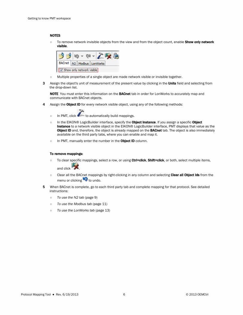
○ To remove network invisible objects from the view and from the object count, enable Show only network visible.
○ Multiple properties of a single object are made network visible or invisible together.
3 Assign the object's unit of measurement of the present value by clicking in the Units field and selecting from the drop-down list.
NOTE You must enter this information on the BACnet tab in order for LonWorks to accurately map and communicate with BACnet objects.
4 Assign the Object ID for every network visible object, using any of the following methods:
○ In PMT, click to automatically build mappings.
○ In the EIKON® LogicBuilder interface, specify the Object Instance. If you assign a specific Object Instance to a network visible object in the EIKON® LogicBuilder interface, PMT displays that value as the Object ID and, therefore, the object is already mapped on the BACnet tab. The object is also immediately available on the third party tabs, where you can enable and map it.
○ In PMT, manually enter the number in the Object ID column.
To remove mappings:
○ To clear specific mappings, select a row, or using Ctrl+click, Shift+click, or both, select multiple items,
and click .
○ Clear all the BACnet mappings by right-clicking in any column and selecting Clear all Object Ids from the menu or clicking to undo.
5 When BACnet is complete, go to each third party tab and complete mapping for that protocol. See detailed instructions:
○ To use the N2 tab (page 9)
○ To use the Modbus tab (page 11)
○ To use the LonWorks tab (page 13)
Protocol Mapping Tool ● Rev. 6/19/2013 6 © 2013 OEMCtrl
Getting to know PMT workspace
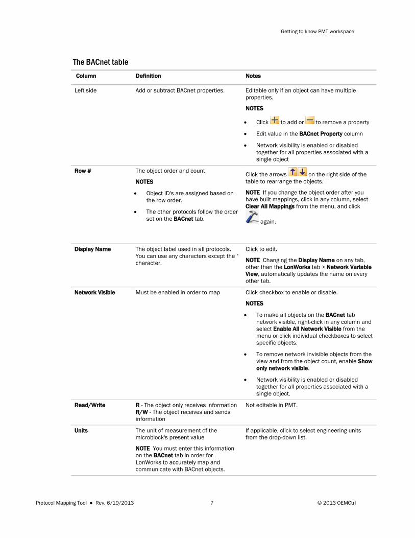
The BACnet table Column Definition Notes
Left side Add or subtract BACnet properties. Editable only if an object can have multiple properties.
NOTES
• Click to add or to remove a property
• Edit value in the BACnet Property column
• Network visibility is enabled or disabled together for all properties associated with a single object
Row # The object order and count
NOTES
• Object ID's are assigned based on the row order.
• The other protocols follow the order set on the BACnet tab.
Click the arrows on the right side of the table to rearrange the objects.
NOTE If you change the object order after you have built mappings, click in any column, select Clear All Mappings from the menu, and click
again.
Display Name The object label used in all protocols. You can use any characters except the " character.
Click to edit.
NOTE Changing the Display Name on any tab, other than the LonWorks tab > Network Variable View, automatically updates the name on every other tab.
Network Visible Must be enabled in order to map
Click checkbox to enable or disable.
NOTES
• To make all objects on the BACnet tab network visible, right-click in any column and select Enable All Network Visible from the menu or click individual checkboxes to select specific objects.
• To remove network invisible objects from the view and from the object count, enable Show only network visible.
• Network visibility is enabled or disabled together for all properties associated with a single object.
Read/Write R - The object only receives information R/W - The object receives and sends information
Not editable in PMT.
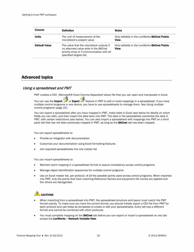
Units The unit of measurement of the microblock's present value
NOTE You must enter this information on the BACnet tab in order for LonWorks to accurately map and communicate with BACnet objects.
If applicable, click to select engineering units from the drop-down list.
Protocol Mapping Tool ● Rev. 6/19/2013 7 © 2013 OEMCtrl

Getting to know PMT workspace
Column Definition Notes
Default Value The value that the microblock outputs if no alternate value exits in the BACnet priority array or if communication with all specified targets fail.
Click to enter a value.
Reference Name A unique alphanumeric string that defines the BACnet object. You assign this in the EIKON® LogicBuilder interface.
NOTES
• The LonWorks network variable name is derived from your BACnet Reference Name and has a limit of 16 characters. The BACnet names are truncated for LonWorks, which can create duplicates. You can avoid this by making the Reference Name short and unique in the EIKON® LogicBuilder interface before you open PMT.
• If you have more than one control program for a single device, see Using multiple control programs (page 22) for advanced details on Reference Name.
Not editable in PMT.
Object Type An identifier that describes the specific type of BACnet object, such as an analog input, binary output, etc..
Not editable in PMT.
Object ID Displays the BACnet object identification number
• A number is present in this field when you open PMT if you have specified that value in the EIKON® LogicBuilder interface, in the microblock, under BACnet Configuration > Object Instance > Use specific value.
• 0 indicates that either there is no assigned ID or the object is not network visible.
• Object ID's are assigned by PMT in the order of their appearance on the tab (the Row #) and by object type.
• Click to assign a number (1 to 9,999,999).
• Right-click in any column to select Set starting build value from the menu.
• If you have assigned a specific Object Instance to an object in the EIKON® LogicBuilder interface, that object already has the Object ID and, is therefore, already mapped on the BACnet tab. It is visible on the other tabs, but is not mapped.
BACnet Property The microblock property you want to read from or write to
Click to select from the drop-down list.
Protocol Mapping Tool ● Rev. 6/19/2013 8 © 2013 OEMCtrl
Getting to know PMT workspace
To use the N2 tab
1 If needed, make changes in the editable fields. See table below for details.
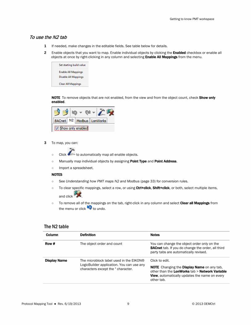
2 Enable objects that you want to map. Enable individual objects by clicking the Enabled checkbox or enable all objects at once by right-clicking in any column and selecting Enable All Mappings from the menu.
NOTE To remove objects that are not enabled, from the view and from the object count, check Show only enabled.
3 To map, you can:
○ Click to automatically map all enable objects.
○ Manually map individual objects by assigning Point Type and Point Address.
○ Import a spreadsheet.
NOTES
○ See Understanding how PMT maps N2 and Modbus (page 33) for conversion rules.
○ To clear specific mappings, select a row, or using Ctrl+click, Shift+click, or both, select multiple items,
and click .
○ To remove all of the mappings on the tab, right-click in any column and select Clear all Mappings from the menu or click to undo.
The N2 table Column Definition Notes
Row # The object order and count
You can change the object order only on the BACnet tab. If you do change the order, all third party tabs are automatically revised.
Display Name The microblock label used in the EIKON® LogicBuilder application. You can use any characters except the " character.
Click to edit.
NOTE Changing the Display Name on any tab, other than the LonWorks tab > Network Variable View, automatically updates the name on every other tab.
Protocol Mapping Tool ● Rev. 6/19/2013 9 © 2013 OEMCtrl
Getting to know PMT workspace
Column Definition Notes
Read/Write R - The object only receives information R/W - The object receives and sends information
Not editable in PMT.
Units The unit of measurement of the microblock's present value
If applicable, click to select engineering units from the drop-down list.
Default Value The value that the microblock outputs if no alternate value exits in the BACnet priority array or if communication with all specified targets fail.
Click to enter a value or select from the drop-down list.
Reference Name This is designated in the microblock in the EIKON® LogicBuilder interface.
Not editable in PMT.
Object Type An identifier that describes the specific type of BACnet object, such as an analog input, binary output, etc..
Not editable in PMT.
BACnet Property You can assign this only on the BACnet tab.
Not editable on the N2 tab.
Enabled Only enabled objects can be mapped. You can enable individual objects by clicking the Enabled checkbox or enable all objects at once by right-clicking in any column and selecting Enable All Mappings from the menu.
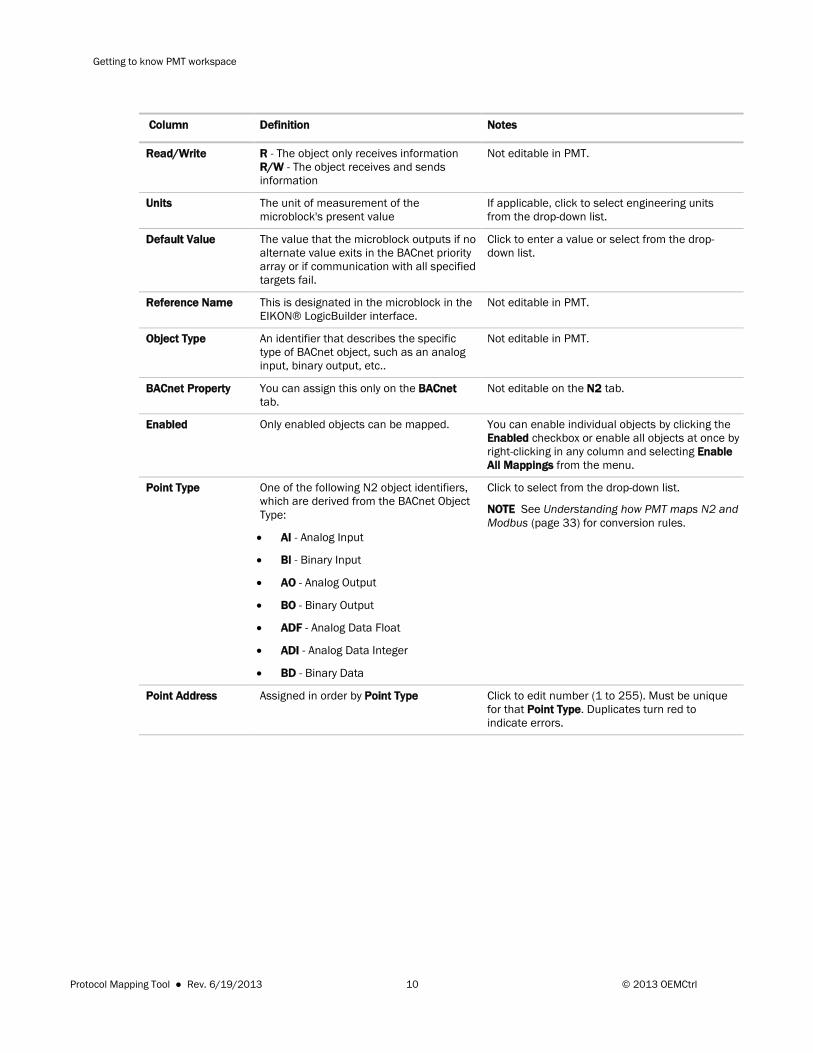
Point Type One of the following N2 object identifiers, which are derived from the BACnet Object Type:
• AI - Analog Input
• BI - Binary Input
• AO - Analog Output
• BO - Binary Output
• ADF - Analog Data Float
• ADI - Analog Data Integer
• BD - Binary Data
Click to select from the drop-down list.
NOTE See Understanding how PMT maps N2 and Modbus (page 33) for conversion rules.
Point Address Assigned in order by Point Type Click to edit number (1 to 255). Must be unique for that Point Type. Duplicates turn red to indicate errors.
Protocol Mapping Tool ● Rev. 6/19/2013 10 © 2013 OEMCtrl
Getting to know PMT workspace
To use the Modbus tab
1 If needed, make changes in the editable fields. See table below for details.
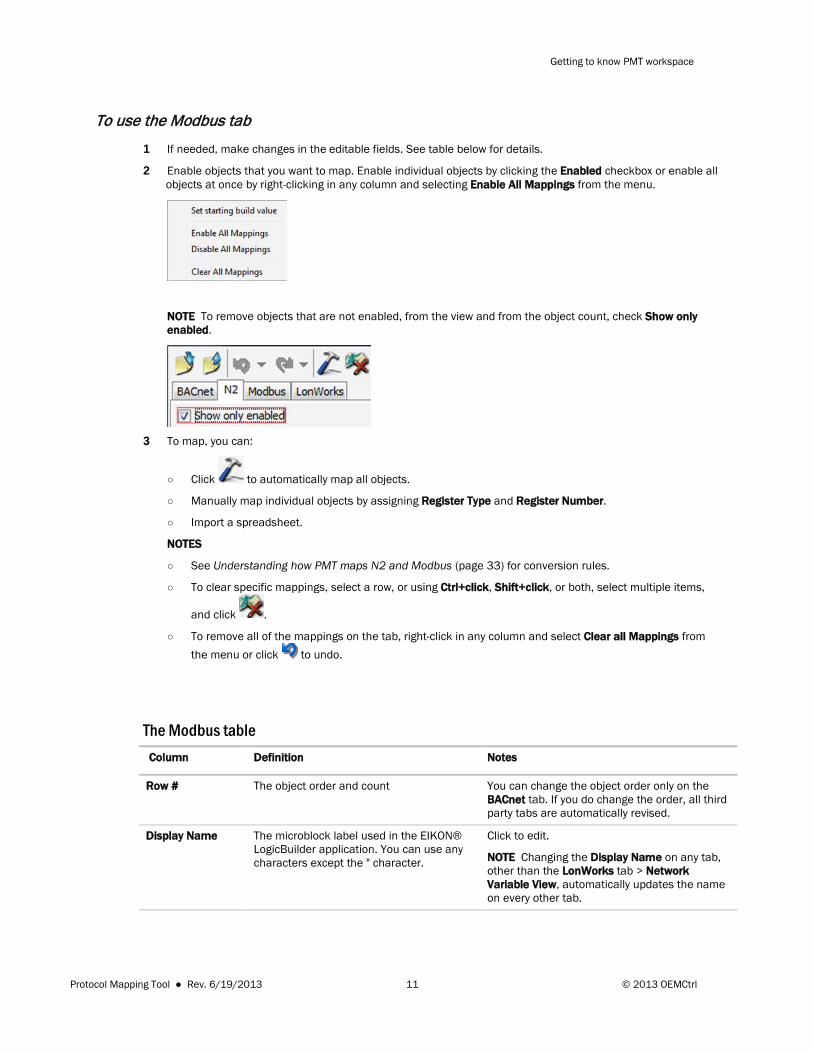
2 Enable objects that you want to map. Enable individual objects by clicking the Enabled checkbox or enable all objects at once by right-clicking in any column and selecting Enable All Mappings from the menu.
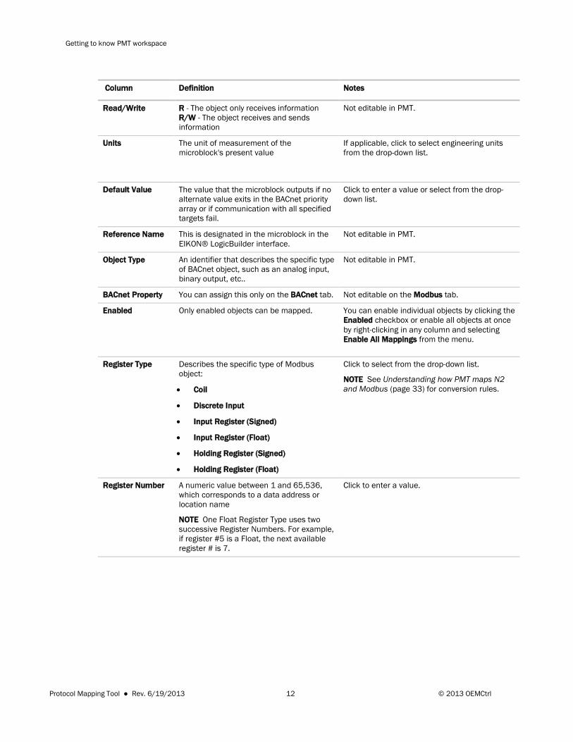
NOTE To remove objects that are not enabled, from the view and from the object count, check Show only enabled.
3 To map, you can:
○ Click to automatically map all objects.
○ Manually map individual objects by assigning Register Type and Register Number.
○ Import a spreadsheet.
NOTES
○ See Understanding how PMT maps N2 and Modbus (page 33) for conversion rules.
○ To clear specific mappings, select a row, or using Ctrl+click, Shift+click, or both, select multiple items,
and click .
○ To remove all of the mappings on the tab, right-click in any column and select Clear all Mappings from the menu or click to undo.
The Modbus table Column Definition Notes
Row # The object order and count You can change the object order only on the BACnet tab. If you do change the order, all third party tabs are automatically revised.
Display Name The microblock label used in the EIKON® LogicBuilder application. You can use any characters except the " character.
Click to edit.
NOTE Changing the Display Name on any tab, other than the LonWorks tab > Network Variable View, automatically updates the name on every other tab.
Protocol Mapping Tool ● Rev. 6/19/2013 11 © 2013 OEMCtrl
Getting to know PMT workspace
Column Definition Notes
Read/Write R - The object only receives information R/W - The object receives and sends information
Not editable in PMT.
Units The unit of measurement of the microblock's present value
If applicable, click to select engineering units from the drop-down list.
Default Value The value that the microblock outputs if no alternate value exits in the BACnet priority array or if communication with all specified targets fail.
Click to enter a value or select from the drop-down list.
Reference Name This is designated in the microblock in the EIKON® LogicBuilder interface.
Not editable in PMT.
Object Type An identifier that describes the specific type of BACnet object, such as an analog input, binary output, etc..
Not editable in PMT.
BACnet Property You can assign this only on the BACnet tab. Not editable on the Modbus tab.
Enabled Only enabled objects can be mapped.
You can enable individual objects by clicking the Enabled checkbox or enable all objects at once by right-clicking in any column and selecting Enable All Mappings from the menu.
Register Type Describes the specific type of Modbus object:
• Coil
• Discrete Input
• Input Register (Signed)
• Input Register (Float)
• Holding Register (Signed)
• Holding Register (Float)
Click to select from the drop-down list.
NOTE See Understanding how PMT maps N2 and Modbus (page 33) for conversion rules.
Register Number A numeric value between 1 and 65,536, which corresponds to a data address or location name
NOTE One Float Register Type uses two successive Register Numbers. For example, if register #5 is a Float, the next available register # is 7.
Click to enter a value.
Protocol Mapping Tool ● Rev. 6/19/2013 12 © 2013 OEMCtrl
Getting to know PMT workspace
To use the LonWorks tab The LonWorks tab has 2 different views.
• The BACnet Points View (page 14)has the same basic layout as the N2 and Modbus tabs. You can use this view to complete the LonWorks mappings if you do not need to conform to an existing LonWorks points list,
such as a LonWorks functional profile. We recommend this view for most users. You can click to automatically build mappings only in this LonWorks view.
• The Network Variable View (page 17) has a LonWorks-centric format. If LonWorks has been mapped in the LonWorks > BACnet Points View, this view displays the same mappings, but the LonWorks addressing is primary. If you have not mapped LonWorks in the BACnet Points View, this view is blank until you manually enter mappings or import from a spreadsheet. Mapping in this view is primarily for more advanced users that are very familiar with LonWorks and have to map according to a pre-defined list of LonWorks network variables.
CAUTIONS
• You must define a Program Id for the device to communicate on the LonWorks network.
• You must use the same Program Id for all control programs in a single device.
Program Id A definition of the control sequences in the device.
The limits are:
• Use 8 characters or less if you do not begin the Id with 8 or 9
• If you begin the Id with 8 or 9, it is an SPID (Standard Program ID), and you must use exactly 16 hexadecimal characters with no spaces or colons
Self Doc String A text string with a device, network variable, or configuration property that is stored within a device interface (XIF) file. Network tools can read the self-documentation strings from the device itself or from the device interface file.
Type a meaningful character string. There are no limits. Use any text, punctuation, numbers, or characters.
TIPS
• Click to select only the columns you want to display.
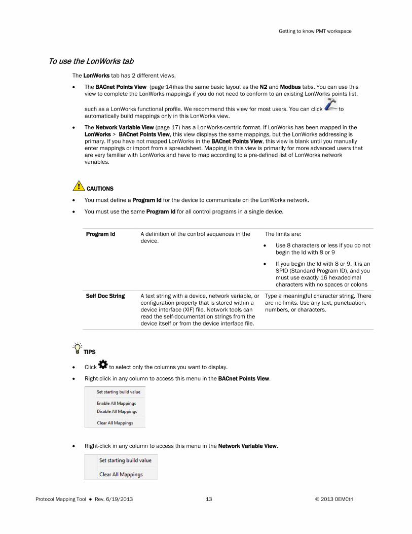
• Right-click in any column to access this menu in the BACnet Points View.
• Right-click in any column to access this menu in the Network Variable View.
Protocol Mapping Tool ● Rev. 6/19/2013 13 © 2013 OEMCtrl

Getting to know PMT workspace
• If you have more than one control program for a single controller and you want to use the Set a starting build value feature, you must assign the value before you map. See Using multiple control programs (page 22).
LonWorks BACnet Points View
On the LonWorks tab, only the BACnet Points View allows you to build mappings automatically by clicking . This populates the Network Variable View with LonWorks and BACnet data. If you do not automatically map, you can manually map or import from a spreadsheet in the BACnet Points View or in the Network Variable View.
See Using multiple control programs (page 22) if you have more than one LonWorks control program in a single device.
CAUTION The LonWorks Option Card allows a total of 62 Network Variables and an SLTA allows up to 4,000 Network Variables.
1 Enable all objects that you want to map. You can enable individual objects by clicking the Enabled checkbox or enable all objects at once by right-clicking in any column and selecting Enable All Mappings from the menu.
NOTE To remove objects that are not enabled, from the view and from the object count, check Show only enabled.
2 To map, you can:
○ Click to automatically map the protocol
○ Manually map individual objects in the BACnet Points View by assigning the NV Name, Direction, SNVT, and Element.
○ Import a spreadsheet.
NOTES
○ When you map an object in the BACnet Points View, the objects and mappings appear on the Network Variable View. You can also map LonWorks manually or by importing a spreadsheet in the Network Variable View without mapping on the BACnet Points View.
○ To clear specific mappings, select a row, or using Ctrl+click, Shift+click, or both, select multiple items,
and click .
Protocol Mapping Tool ● Rev. 6/19/2013 14 © 2013 OEMCtrl
Getting to know PMT workspace
○ To remove all of the mappings on the tab, right-click in any column and select Clear all Mappings from the menu or click to undo.
3 You can select the Network Variable View to manage more detailed LonWorks data. See Network Variable View (page 17).
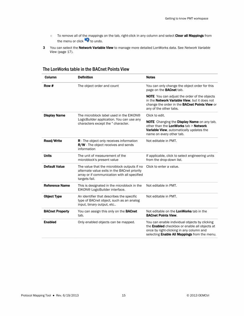
The LonWorks table in the BACnet Points View Column Definition Notes
Row # The object order and count You can only change the object order for this page on the BACnet tab.
NOTE You can adjust the order of the objects in the Network Variable View, but it does not change the order in the BACnet Points View or any of the other tabs.
Display Name The microblock label used in the EIKON® LogicBuilder application. You can use any characters except the " character.
Click to edit.
NOTE Changing the Display Name on any tab, other than the LonWorks tab > Network Variable View, automatically updates the name on every other tab.
Read/Write R - The object only receives information R/W - The object receives and sends information
Not editable in PMT.
Units The unit of measurement of the microblock's present value
If applicable, click to select engineering units from the drop-down list.
Default Value The value that the microblock outputs if no alternate value exits in the BACnet priority array or if communication with all specified targets fail.
Click to enter a value.
Reference Name This is designated in the microblock in the EIKON® LogicBuilder interface.
Not editable in PMT.
Object Type An identifier that describes the specific type of BACnet object, such as an analog input, binary output, etc..
Not editable in PMT.
BACnet Property You can assign this only on the BACnet tab.
Not editable on the LonWorks tab in the BACnet Points View.
Enabled Only enabled objects can be mapped. You can enable individual objects by clicking the Enabled checkbox or enable all objects at once by right-clicking in any column and selecting Enable All Mappings from the menu.
Protocol Mapping Tool ● Rev. 6/19/2013 15 © 2013 OEMCtrl
Getting to know PMT workspace
Column Definition Notes
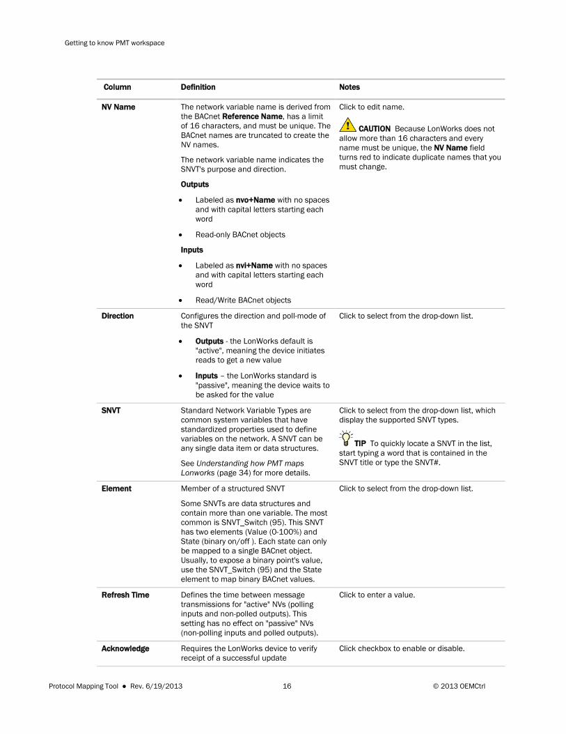
NV Name The network variable name is derived from the BACnet Reference Name, has a limit of 16 characters, and must be unique. The BACnet names are truncated to create the NV names.
The network variable name indicates the SNVT's purpose and direction.
Outputs
• Labeled as nvo+Name with no spaces and with capital letters starting each word
• Read-only BACnet objects
Inputs
• Labeled as nvi+Name with no spaces and with capital letters starting each word
• Read/Write BACnet objects
Click to edit name.
CAUTION Because LonWorks does not allow more than 16 characters and every name must be unique, the NV Name field turns red to indicate duplicate names that you must change.
Direction Configures the direction and poll-mode of the SNVT
• Outputs - the LonWorks default is "active", meaning the device initiates reads to get a new value
• Inputs – the LonWorks standard is "passive", meaning the device waits to be asked for the value
Click to select from the drop-down list.
SNVT Standard Network Variable Types are common system variables that have standardized properties used to define variables on the network. A SNVT can be any single data item or data structures.
See Understanding how PMT maps Lonworks (page 34) for more details.
Click to select from the drop-down list, which display the supported SNVT types.
TIP To quickly locate a SNVT in the list, start typing a word that is contained in the SNVT title or type the SNVT#.
Element Member of a structured SNVT
Some SNVTs are data structures and contain more than one variable. The most common is SNVT_Switch (95). This SNVT has two elements (Value (0-100%) and State (binary on/off ). Each state can only be mapped to a single BACnet object. Usually, to expose a binary point's value, use the SNVT_Switch (95) and the State element to map binary BACnet values.
Click to select from the drop-down list.
Refresh Time Defines the time between message transmissions for "active" NVs (polling inputs and non-polled outputs). This setting has no effect on "passive" NVs (non-polling inputs and polled outputs).
Click to enter a value.
Acknowledge Requires the LonWorks device to verify receipt of a successful update
Click checkbox to enable or disable.
Protocol Mapping Tool ● Rev. 6/19/2013 16 © 2013 OEMCtrl
Getting to know PMT workspace
Column Definition Notes
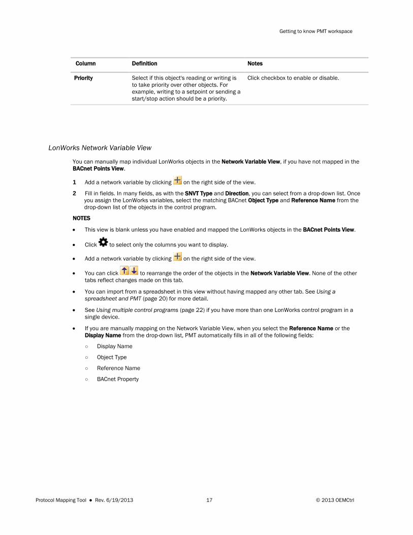
Priority Select if this object's reading or writing is to take priority over other objects. For example, writing to a setpoint or sending a start/stop action should be a priority.
Click checkbox to enable or disable.
LonWorks Network Variable View
You can manually map individual LonWorks objects in the Network Variable View, if you have not mapped in the BACnet Points View.
1 Add a network variable by clicking on the right side of the view.
2 Fill in fields. In many fields, as with the SNVT Type and Direction, you can select from a drop-down list. Once you assign the LonWorks variables, select the matching BACnet Object Type and Reference Name from the drop-down list of the objects in the control program.
NOTES
• This view is blank unless you have enabled and mapped the LonWorks objects in the BACnet Points View.
• Click to select only the columns you want to display.
• Add a network variable by clicking on the right side of the view.
• You can click to rearrange the order of the objects in the Network Variable View. None of the other tabs reflect changes made on this tab.
• You can import from a spreadsheet in this view without having mapped any other tab. See Using a spreadsheet and PMT (page 20) for more detail.
• See Using multiple control programs (page 22) if you have more than one LonWorks control program in a single device.
• If you are manually mapping on the Network Variable View, when you select the Reference Name or the Display Name from the drop-down list, PMT automatically fills in all of the following fields:
○ Display Name
○ Object Type
○ Reference Name
○ BACnet Property
Protocol Mapping Tool ● Rev. 6/19/2013 17 © 2013 OEMCtrl
Getting to know PMT workspace
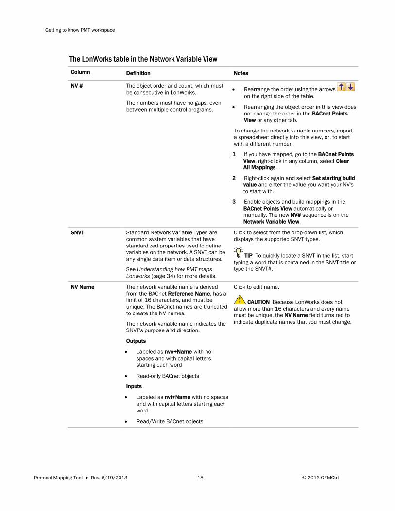
The LonWorks table in the Network Variable View Column Definition Notes
NV # The object order and count, which must be consecutive in LonWorks.
The numbers must have no gaps, even between multiple control programs.
• Rearrange the order using the arrows on the right side of the table.
• Rearranging the object order in this view does not change the order in the BACnet Points View or any other tab.
To change the network variable numbers, import a spreadsheet directly into this view, or, to start with a different number:
1 If you have mapped, go to the BACnet Points View, right-click in any column, select Clear All Mappings.
2 Right-click again and select Set starting build value and enter the value you want your NV's to start with.
3 Enable objects and build mappings in the BACnet Points View automatically or manually. The new NV# sequence is on the Network Variable View.
SNVT Standard Network Variable Types are common system variables that have standardized properties used to define variables on the network. A SNVT can be any single data item or data structures.
See Understanding how PMT maps Lonworks (page 34) for more details.
Click to select from the drop-down list, which displays the supported SNVT types.
TIP To quickly locate a SNVT in the list, start typing a word that is contained in the SNVT title or type the SNVT#.
NV Name The network variable name is derived from the BACnet Reference Name, has a limit of 16 characters, and must be unique. The BACnet names are truncated to create the NV names.
The network variable name indicates the SNVT's purpose and direction.
Outputs
• Labeled as nvo+Name with no spaces and with capital letters starting each word
• Read-only BACnet objects
Inputs
• Labeled as nvi+Name with no spaces and with capital letters starting each word
• Read/Write BACnet objects
Click to edit name.
CAUTION Because LonWorks does not allow more than 16 characters and every name must be unique, the NV Name field turns red to indicate duplicate names that you must change.
Protocol Mapping Tool ● Rev. 6/19/2013 18 © 2013 OEMCtrl
Getting to know PMT workspace
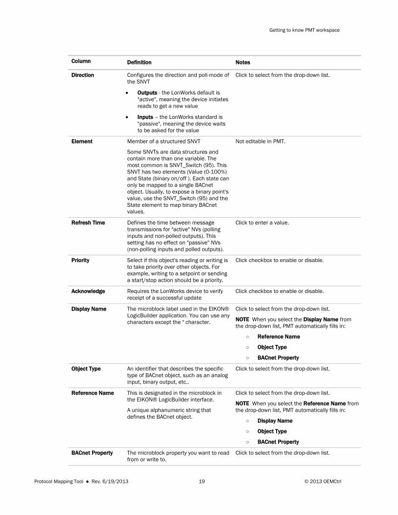
Column Definition Notes
Direction Configures the direction and poll-mode of the SNVT
• Outputs - the LonWorks default is "active", meaning the device initiates reads to get a new value
• Inputs – the LonWorks standard is "passive", meaning the device waits to be asked for the value
Click to select from the drop-down list.
Element Member of a structured SNVT
Some SNVTs are data structures and contain more than one variable. The most common is SNVT_Switch (95). This SNVT has two elements (Value (0-100%) and State (binary on/off ). Each state can only be mapped to a single BACnet object. Usually, to expose a binary point's value, use the SNVT_Switch (95) and the State element to map binary BACnet values.
Not editable in PMT.
Refresh Time Defines the time between message transmissions for "active" NVs (polling inputs and non-polled outputs). This setting has no effect on "passive" NVs (non-polling inputs and polled outputs).
Click to enter a value.
Priority Select if this object's reading or writing is to take priority over other objects. For example, writing to a setpoint or sending a start/stop action should be a priority.
Click checkbox to enable or disable.
Acknowledge Requires the LonWorks device to verify receipt of a successful update
Click checkbox to enable or disable.
Display Name The microblock label used in the EIKON® LogicBuilder application. You can use any characters except the " character.
Click to select from the drop-down list.
NOTE When you select the Display Name from the drop-down list, PMT automatically fills in:
○ Reference Name
○ Object Type
○ BACnet Property
Object Type An identifier that describes the specific type of BACnet object, such as an analog input, binary output, etc..
Click to select from the drop-down list.
Reference Name This is designated in the microblock in the EIKON® LogicBuilder interface.
A unique alphanumeric string that defines the BACnet object.
Click to select from the drop-down list.
NOTE When you select the Reference Name from the drop-down list, PMT automatically fills in:
○ Display Name
○ Object Type
○ BACnet Property
BACnet Property The microblock property you want to read from or write to.
Click to select from the drop-down list.
Protocol Mapping Tool ● Rev. 6/19/2013 19 © 2013 OEMCtrl
Getting to know PMT workspace
Column Definition Notes
Units The unit of measurement of the microblock's present value
Only editable in the LonWorks BACnet Points View.
Default Value The value that the microblock outputs if no alternate value exits in the BACnet priority array or if communication with all specified targets fail.
Only editable in the LonWorks BACnet Points View.
Advanced topics
Using a spreadsheet and PMT PMT creates a CSV (Microsoft® Excel Comma Separated Value) file that you can open and manipulate in Excel.
You can use the Import or Export feature in PMT to edit or build mappings in a spreadsheet. If you have multiple control programs in one device, you have to use spreadsheets to manage them. See Using multiple control programs (page 22).
You can export a spreadsheet after you have mapped in PMT, make edits in Excel (see below for details on which fields you can edit), and then import the data back into PMT. The data in the spreadsheet overwrites the data in PMT, with certain restrictions (see below). You can also import a spreadsheet with mappings into PMT on a third party tab that has not been previously mapped in PMT, as long as the BACnet tab has been mapped.
You can export spreadsheets to:
• Provide an integrator with documentation
• Customize your documentation using Excel formatting features
• Join exported spreadsheets into one master list
You can import spreadsheets to:
• Maintain point mapping in a spreadsheet format to assure consistency across control programs
• Manage object identification sequences for multiple control programs
• Use an Excel master list, per protocol, of all the possible points used across control programs. When imported into PMT, only the points that have matching Reference Names and equipment file names are applied and the others are disregarded.
CAUTIONS
• When importing from a spreadsheet into PMT, the spreadsheet structure and layout must match the PMT format exactly. To make sure you have the correct format, you should initially export a CSV file from PMT for each protocol and use these as templates to create or edit your spreadsheets. Every tab has a different format and cannot be combined with other protocols.
• You must complete mapping on the BACnet tab before you can export or import a spreadsheet on any tab except the LonWorks > Network Variable View.
Protocol Mapping Tool ● Rev. 6/19/2013 20 © 2013 OEMCtrl

Getting to know PMT workspace
• The Reference Name of the microblock in the EIKON® LogicBuilder interface must match the Reference Name on your spreadsheet. If you have objects with Reference Name discrepancies, all the changes for that object are rejected. If the Reference Name matches, any disallowed changes are ignored and acceptable changes are imported.
• When you export, if you have checked Show only network visible on the BACnet tab or Show only enabled on the N2, Modbus, or LonWorks tabs, it must also be checked when you import a spreadsheet.
• PMT does not import any change made in a field that is non-editable (grayed out) in PMT.
To export, edit, and import a spreadsheet
1 You must import or export one protocol at a time from each tab.
2 Click Export to create a CSV file.
3 Save the file as a .csv to a convenient location.
NOTE If you see this dialog, click Yes.
4 In PMT, minimize the window or click Close or to exit.
5 Open your spreadsheet in Excel. If you browse to your file from Excel and do not see it listed, be sure to select All Files (not All Excel Files) from the Excel drop-down list.
6 Edit and save as a .csv file.
7 In PMT, verify that you are on the same protocol tab as your spreadsheet.
8 Click to import your data.
9 Browse to the spreadsheet and click Open.
NOTE If PMT finds Reference Name mismatches, a warning screen lists the objects that could not be mapped. Print this list to help you resolve errors and import again. See CAUTIONS listed above for more details on discrepancies.
10 Repeat these steps for each protocol.
Protocol Mapping Tool ● Rev. 6/19/2013 21 © 2013 OEMCtrl
Getting to know PMT workspace
Lonworks > Network Variable View
This tab behaves differently than all of the others because it is LonWorks-centric and not BACnet-based.
CAUTIONS
• You cannot have duplicate NV Names. Because PMT makes the NV Name by truncating the BACnet Reference Name, duplicates are common. The field turns red in PMT as a warning that it is a duplicate. You can modify the names in the PMT interface in the LonWorks tab > Network Variable View or by importing a spreadsheet.
• To import successfully, all Network Variable Numbers must be consecutive and have NO gaps.
• To clear objects that you may not want, you cannot use Clear All Mappings on the Network Variable View because this only clears the BACnet information. To clear the LonWorks information, you must select the object (or multi-select several objects) and click Delete .
Using multiple control programs PMT processes one control program at a time and does not keep track of multiple control programs that might be loaded in a single device. Because you must have unique Reference Names and unique object identification numbers across all the programs, you have to manage these outside of the PMT interface.
NOTE In LonWorks, you must use the same Program Id's for all control programs in a single device.
Managing Reference Names
BACnet Reference Name
There are different methods for ensuring every Reference Name is unique throughout all control programs. You can only change the Reference Name in the EIKON® LogicBuilder interface. You cannot change Reference Names in PMT or in a spreadsheet that you will import because PMT only imports names that match exactly what is already in it.
NOTES
• Make the BACnet Reference Names as short as possible because LonWorks Network Variable Names are derived from the BACnet Reference Name and LonWorks does not allow more than 16 characters. 3 of those are always nvo or nvi and one character is for the control program number. We recommend your BACnet Reference Name have no more than 12 characters.
• We recommend that you append a number to each name which corresponds to the control program's order in which it is attached to the device. You can use the scripting file (see instructions below) to accomplish this.
Protocol Mapping Tool ● Rev. 6/19/2013 22 © 2013 OEMCtrl
Getting to know PMT workspace
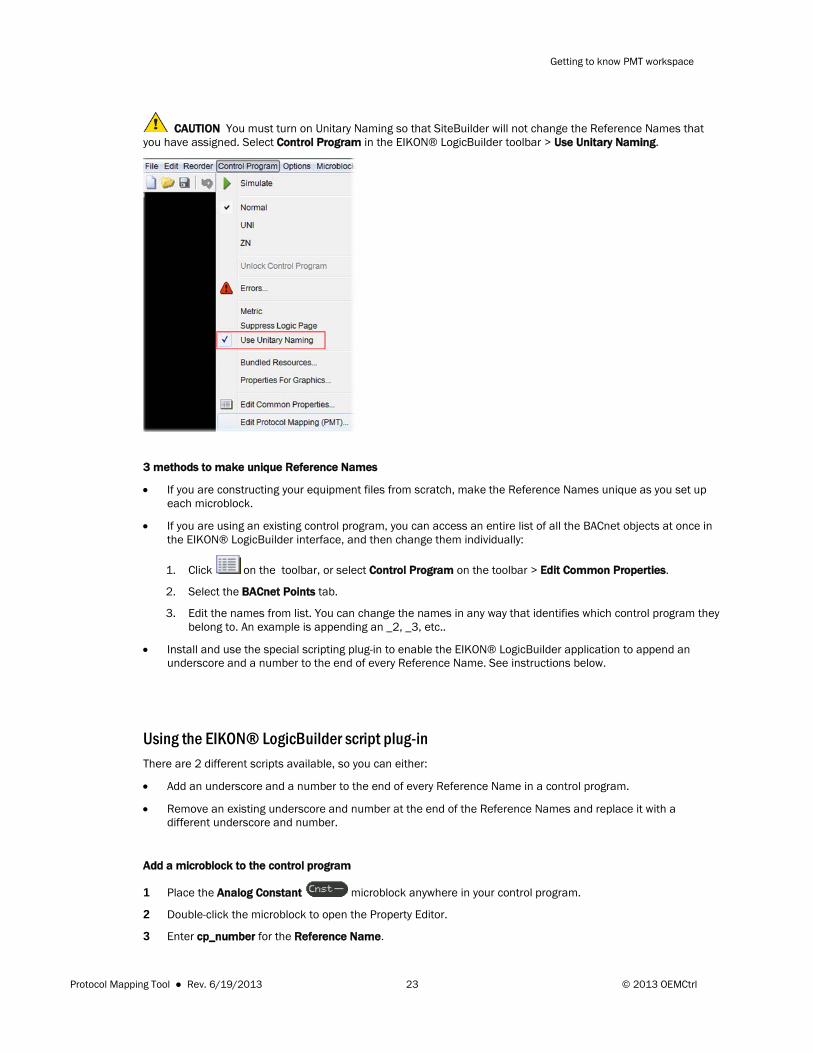
CAUTION You must turn on Unitary Naming so that SiteBuilder will not change the Reference Names that you have assigned. Select Control Program in the EIKON® LogicBuilder toolbar > Use Unitary Naming.
3 methods to make unique Reference Names
• If you are constructing your equipment files from scratch, make the Reference Names unique as you set up each microblock.
• If you are using an existing control program, you can access an entire list of all the BACnet objects at once in the EIKON® LogicBuilder interface, and then change them individually:
1. Click on the toolbar, or select Control Program on the toolbar > Edit Common Properties.
2. Select the BACnet Points tab.
3. Edit the names from list. You can change the names in any way that identifies which control program they belong to. An example is appending an _2, _3, etc..
• Install and use the special scripting plug-in to enable the EIKON® LogicBuilder application to append an underscore and a number to the end of every Reference Name. See instructions below.
Using the EIKON® LogicBuilder script plug-in There are 2 different scripts available, so you can either:
• Add an underscore and a number to the end of every Reference Name in a control program.
• Remove an existing underscore and number at the end of the Reference Names and replace it with a different underscore and number.
Add a microblock to the control program
1 Place the Analog Constant microblock anywhere in your control program.
2 Double-click the microblock to open the Property Editor.
3 Enter cp_number for the Reference Name.
Protocol Mapping Tool ● Rev. 6/19/2013 23 © 2013 OEMCtrl

Getting to know PMT workspace
4 Enter the number that you want to be appended to the Reference Names in this control program in Present Value.
NOTE The number must correlate with the order that the control programs will be attached to the device.
Install the scripting file
1 Obtain the scripting files (.logic-plugin and .logic-script) from your Automated Logic® representative.
2 Copy the .logic-plugin file into your Field Assistant folder > extras > add-ons.
3 Open the EIKON® LogicBuilder application.
4 Select Tools > Configure Tools.
5 Click Add in the dialog box.
6 Select the .logic-plugin file and click Open.
7 Click OK.
8 Copy the .logic.script file into the Field Assistant folder > resources > logicbuilder > plugins > script > folder.
9 In the EIKON® LogicBuilder interface, select Tools > Scripts > Configure.
10 Click Add in the dialog box.
11 Browse to your .logic-script file in the Field Assistant folder.
12 Click OK.
13 In the EIKON® LogicBuilder interface, select Tools > Scripts > your .logic-script file.
14 Click Execute in the dialog. When finished, the message Execution Completed Successfully displays under Output.
15 In the EIKON® LogicBuilder interface, select Control Program > Edit Protocol Mapping (PMT) to check the names in the Reference Name column.
LonWorks Network Variable Names
If you do not use scripting, you can make the LonWorks Network Variable Names unique by changing the names in PMT on the LonWorks tab > Network Variable View, in the NV Name field. Or, you can change them in a spreadsheet and import them. This is the only tab you can alter the Reference Names on. See Managing multiple control programs with spreadsheets (page 26).
Managing object identification numbers
Object identification numbers
The object identification number for each protocol is the:
• BACnet Object ID
• N2 Point Address
• Modbus Register Number
• LonWorks Network Variable Number (NV#)
Protocol Mapping Tool ● Rev. 6/19/2013 24 © 2013 OEMCtrl

Getting to know PMT workspace
PMT automatically starts the object identification sequence for each object type in every protocol with 1. Therefore, programs will all have duplicate identification numbers, which you must change for using multiple control programs in one device.
You can assign and enter unique numbers, using one or more of the following methods:
• Method 1: For BACnet objects only, you can assign a number in the EIKON® LogicBuilder interface, in the microblock Property Editor under BACnet Configuration > Object Instance > Use specific value. This method is the best and easiest to implement when you are making your control program from scratch. If you are using a pre-existing control program, one of the other methods may be easier.
• Method 2: In PMT, after you enable the objects, click in the applicable object identification column and individually type in a number for each network visible object.
• Method 3: In PMT, after you enable the objects, but before you map, you can set the numbering to begin with a specific value. On each protocol tab, right-click in any column and select Set starting build value, fill in a
number that has not been used in a previous control program, and click to map. Every object type's identification sequence starts with the value you have assigned for that protocol. This method only works for BACnet and LonWorks, because it results in gaps in your numbering sequences between control programs. N2 and Modbus must not have gaps and need to be assigned in a spreadsheet. For LonWorks, use the following steps to set your numbering.
1. On the LonWorks tab, In the BACnet Points View, right-click in any column to access this menu in the BACnet Points View.
2. Select Clear All Mappings.
3. Select Set starting build value.
4. Enter the next NV# (you can only see this on the Network Variable View) following the last one used in the previous control program. You must have no gaps.
5. In the BACnet Points View, click .
6. Select the Network Variable View the see the NV#'s.
• Method 4: Spreadsheets are often the easiest method to track object identification numbers. You must have separate spreadsheets for each protocol for importing or exporting. See Managing multiple control programs with spreadsheets (page 26) for complete details.
NOTES
○ You cannot import into PMT from a spreadsheet with more than one protocol on it, though you might want to make one for your own use.
○ You can make a master spreadsheet, for each protocol, that contains the mapped objects for all the control programs, by copying and pasting from individually exported spreadsheets. See detailed instructions below. You can import the master into a control program and PMT ignores all data with a different equipment file name.
○ For general details on exporting and importing a CSV file, see Using a spreadsheet and PMT (page 20).
○ If you change the Reference Name in the spreadsheet, or the entire object is rejected from PMT when you import.
Protocol Mapping Tool ● Rev. 6/19/2013 25 © 2013 OEMCtrl
Getting to know PMT workspace
Using spreadsheets to change object identification numbers
Follow these steps to use Excel to help you track and assign the correct object identification numbers to import into PMT. You must make the Reference Names unique before you work with the numbers, so your spreadsheets have the final object names. See Managing Reference Names (page 22).
The spreadsheets exported from your first control program are the basis to build the master spreadsheet. The data from each successive control program is added to the initial spreadsheet to make it easier for you to track the ending number and starting numbers for each object type sequence.
CAUTIONS
• For this method to work, your control programs must have different names.
• Change each control program in the order in which it will be attached to the device.
Set up spreadsheets from initial control program
1 With your first control program open in EIKON® LogicBuilder, open PMT by clicking Control Program > Edit Protocol Mapping (PMT) > BACnet tab.
2 If you have not already assigned the BACnet Object ID's in the EIKON® LogicBuilder interface, make sure that
in the PMT interface, the BACnet objects you want to map are Network Visible and then click to map. For general details, see To use the BACnet tab (page 5).
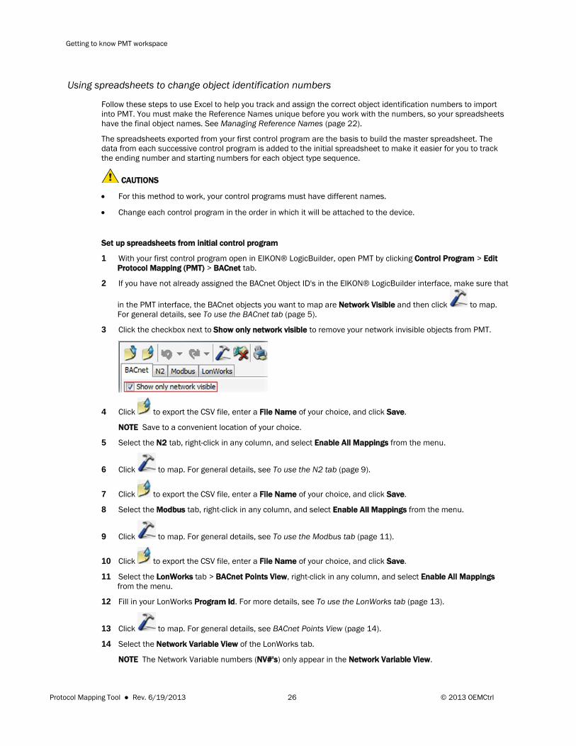
3 Click the checkbox next to Show only network visible to remove your network invisible objects from PMT.
4 Click to export the CSV file, enter a File Name of your choice, and click Save.
NOTE Save to a convenient location of your choice.
5 Select the N2 tab, right-click in any column, and select Enable All Mappings from the menu.
6 Click to map. For general details, see To use the N2 tab (page 9).
7 Click to export the CSV file, enter a File Name of your choice, and click Save.
8 Select the Modbus tab, right-click in any column, and select Enable All Mappings from the menu.
9 Click to map. For general details, see To use the Modbus tab (page 11).
10 Click to export the CSV file, enter a File Name of your choice, and click Save.
11 Select the LonWorks tab > BACnet Points View, right-click in any column, and select Enable All Mappings from the menu.
12 Fill in your LonWorks Program Id. For more details, see To use the LonWorks tab (page 13).
13 Click to map. For general details, see BACnet Points View (page 14).
14 Select the Network Variable View of the LonWorks tab.
NOTE The Network Variable numbers (NV#'s) only appear in the Network Variable View.
Protocol Mapping Tool ● Rev. 6/19/2013 26 © 2013 OEMCtrl
Getting to know PMT workspace
15 Click to export the CSV file, enter a File Name of your choice, and click Save.
16 Close PMT and save your control program.
Add control programs to your spreadsheet and assign successive object identification numbers
In Excel, open your spreadsheets from the first control program to have them readily available. You will use these as the basis to build the master spreadsheet.
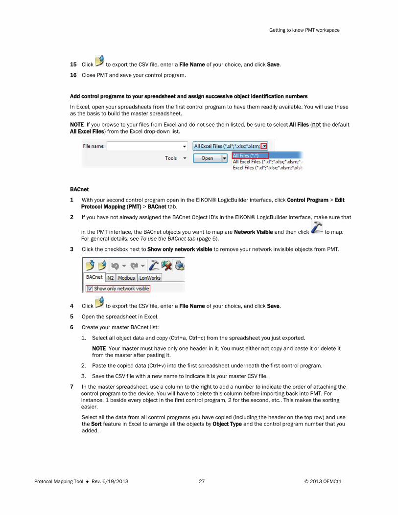
NOTE If you browse to your files from Excel and do not see them listed, be sure to select All Files (not the default All Excel Files) from the Excel drop-down list.
BACnet
1 With your second control program open in the EIKON® LogicBuilder interface, click Control Program > Edit Protocol Mapping (PMT) > BACnet tab.
2 If you have not already assigned the BACnet Object ID's in the EIKON® LogicBuilder interface, make sure that
in the PMT interface, the BACnet objects you want to map are Network Visible and then click to map. For general details, see To use the BACnet tab (page 5).
3 Click the checkbox next to Show only network visible to remove your network invisible objects from PMT.
4 Click to export the CSV file, enter a File Name of your choice, and click Save.
5 Open the spreadsheet in Excel.
6 Create your master BACnet list:
1. Select all object data and copy (Ctrl+a, Ctrl+c) from the spreadsheet you just exported.
NOTE Your master must have only one header in it. You must either not copy and paste it or delete it from the master after pasting it.
2. Paste the copied data (Ctrl+v) into the first spreadsheet underneath the first control program.
3. Save the CSV file with a new name to indicate it is your master CSV file.
7 In the master spreadsheet, use a column to the right to add a number to indicate the order of attaching the control program to the device. You will have to delete this column before importing back into PMT. For instance, 1 beside every object in the first control program, 2 for the second, etc.. This makes the sorting easier.
Select all the data from all control programs you have copied (including the header on the top row) and use the Sort feature in Excel to arrange all the objects by Object Type and the control program number that you added.
Protocol Mapping Tool ● Rev. 6/19/2013 27 © 2013 OEMCtrl
Getting to know PMT workspace
TIP
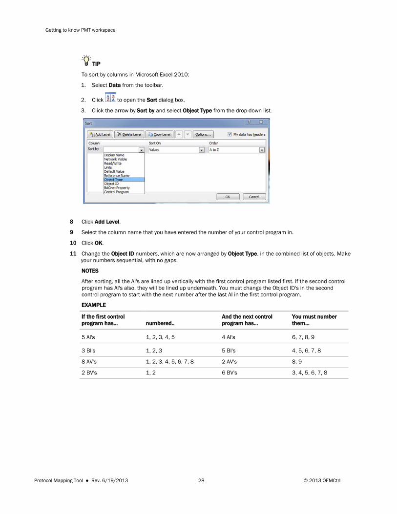
To sort by columns in Microsoft Excel 2010:
1. Select Data from the toolbar.
2. Click to open the Sort dialog box.
3. Click the arrow by Sort by and select Object Type from the drop-down list.
8 Click Add Level.
9 Select the column name that you have entered the number of your control program in.
10 Click OK.
11 Change the Object ID numbers, which are now arranged by Object Type, in the combined list of objects. Make your numbers sequential, with no gaps.
NOTES
After sorting, all the AI's are lined up vertically with the first control program listed first. If the second control program has AI's also, they will be lined up underneath. You must change the Object ID's in the second control program to start with the next number after the last AI in the first control program.
EXAMPLE
If the first control program has... numbered..
And the next control program has...
You must number them...
5 AI's 1, 2, 3, 4, 5 4 AI's 6, 7, 8, 9
3 BI's 1, 2, 3 5 BI's 4, 5, 6, 7, 8
8 AV's 1, 2, 3, 4, 5, 6, 7, 8 2 AV's 8, 9
2 BV's 1, 2 6 BV's 3, 4, 5, 6, 7, 8
Protocol Mapping Tool ● Rev. 6/19/2013 28 © 2013 OEMCtrl
Getting to know PMT workspace
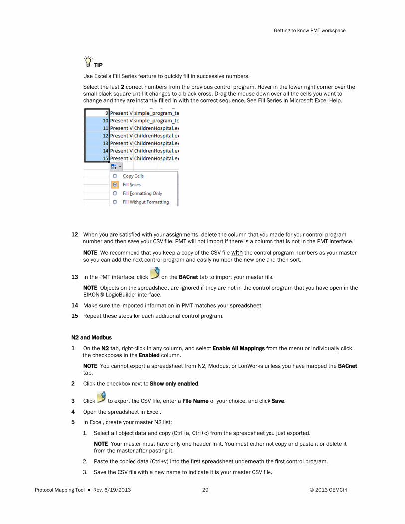
TIP
Use Excel's Fill Series feature to quickly fill in successive numbers.
Select the last 2 correct numbers from the previous control program. Hover in the lower right corner over the small black square until it changes to a black cross. Drag the mouse down over all the cells you want to change and they are instantly filled in with the correct sequence. See Fill Series in Microsoft Excel Help.
12 When you are satisfied with your assignments, delete the column that you made for your control program number and then save your CSV file. PMT will not import if there is a column that is not in the PMT interface.
NOTE We recommend that you keep a copy of the CSV file with the control program numbers as your master so you can add the next control program and easily number the new one and then sort.
13 In the PMT interface, click on the BACnet tab to import your master file.
NOTE Objects on the spreadsheet are ignored if they are not in the control program that you have open in the EIKON® LogicBuilder interface.
14 Make sure the imported information in PMT matches your spreadsheet.
15 Repeat these steps for each additional control program.
N2 and Modbus
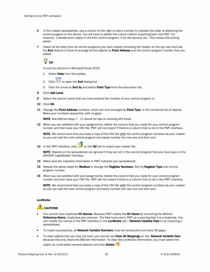
1 On the N2 tab, right-click in any column, and select Enable All Mappings from the menu or individually click the checkboxes in the Enabled column.
NOTE You cannot export a spreadsheet from N2, Modbus, or LonWorks unless you have mapped the BACnet tab.
2 Click the checkbox next to Show only enabled.
3 Click to export the CSV file, enter a File Name of your choice, and click Save.
4 Open the spreadsheet in Excel.
5 In Excel, create your master N2 list:
1. Select all object data and copy (Ctrl+a, Ctrl+c) from the spreadsheet you just exported.
NOTE Your master must have only one header in it. You must either not copy and paste it or delete it from the master after pasting it.
2. Paste the copied data (Ctrl+v) into the first spreadsheet underneath the first control program.
3. Save the CSV file with a new name to indicate it is your master CSV file.
Protocol Mapping Tool ● Rev. 6/19/2013 29 © 2013 OEMCtrl
Getting to know PMT workspace
6 In the master spreadsheet, use a column to the right to add a number to indicate the order of attaching the control program to the device. You will have to delete this column before importing back into PMT. For instance, 1 beside every object in the first control program, 2 for the second, etc.. This makes the sorting easier.
7 Select all the data from all control programs you have copied (including the header on the top row) and use the Sort feature in Excel to arrange all the objects by Point Address and the control program number that you added.
TIP
To sort by columns in Microsoft Excel 2010:
1. Select Data from the toolbar.
2. Click to open the Sort dialog box.
3. Click the arrow by Sort by and select Point Type from the drop-down list.
8 Click Add Level.
9 Select the column name that you have entered the number of your control program in.
10 Click OK.
11 Change the Point Address numbers, which are now arranged by Point Type, in the combined list of objects. Make your numbers sequential, with no gaps.
NOTE See BACnet steps 7 - 11 above for tips on working with Excel.
12 When you are satisfied with your assignments, delete the column that you made for your control program number and then save your CSV file. PMT will not import if there is a column that is not in the PMT interface.
NOTE We recommend that you keep a copy of the CSV file with the control program numbers as your master so you can add the next control program and easily number the new one and then sort.
13 In the PMT interface, click on the N2 tab to import your master file.
NOTE Objects on the spreadsheet are ignored if they are not in the control program that you have open in the EIKON® LogicBuilder interface.
14 Make sure the imported information in PMT matches your spreadsheet.
15 Repeat the above steps for Modbus to change the Register Numbers. Sort by Register Type and control program number.
16 When you are satisfied with your assignments, delete the column that you made for your control program number and then save your CSV file. PMT will not import if there is a column that is not in the PMT interface.
NOTE We recommend that you keep a copy of the CSV file with the control program numbers as your master so you can add the next control program and easily number the new one and then sort.
LonWorks
CAUTIONS
• You cannot have duplicate NV Names. Because PMT makes the NV Name by truncating the BACnet Reference Name, duplicates are common. The field turns red in PMT as a warning that it is a duplicate. You can modify the names in the PMT interface in the LonWorks tab > Network Variable View or by importing a spreadsheet.
• To import successfully, all Network Variable Numbers must be consecutive and have NO gaps.
• To clear objects that you may not want, you cannot use Clear All Mappings on the Network Variable View because this only clears the BACnet information. To clear the LonWorks information, you must select the object (or multi-select several objects) and click Delete .
Protocol Mapping Tool ● Rev. 6/19/2013 30 © 2013 OEMCtrl

Getting to know PMT workspace
• The LonWorks Option Card allows a total of 62 Network Variables and an SLTA allows up to 4,000 Network Variables.
Using Set a starting build value for LonWorks
Because LonWorks has only one object type, the Network Variable, it is easier to change the numbering of the NV#'s using the following method, instead of a spreadsheet:
1 If you have mapped the LonWorks tab > BACnet Points View, you must right-click in any column and select Clear All Mappings from the menu. Skip this step if you have not mapped.
2 Right-click, select Set starting build value from the menu and enter the number that follows the last NV# used in the previous control program.
3 Right-click in any column, and select Enable All Mappings from the menu or individually click the checkboxes in the Enabled column.
4 Click to map. The NV#'s are displayed on the Network Variable View.
Using a spreadsheet for LonWorks
You may want to use a spreadsheet to also change Network Variable Names. Use the above method to change the LonWorks NV#'s. If you want to build a master spreadsheet, follow these steps.
1 On the LonWorks tab > BACnet Points View, right-click in any column, and select Enable All Mappings from the menu or individually click the checkboxes in the Enabled column.
2 Click to map.
NOTE There is no data in the Network Variable View until you either build mappings in the BACnet Points View, or enter objects manually in the Network Variable View.
3 Select the LonWorks tab > Network Variable View.
4 Click to export the CSV file, enter a File Name of your choice, and click Save.
5 Open the spreadsheet in Excel.
6 In Excel, create your master LonWorks list:
1. Select all object data and copy (Ctrl+a, Ctrl+c) from the spreadsheet you just exported.
NOTE Your master must have only one header in it. You must either not copy and paste it or delete it from the master after pasting it.
2. Paste the copied data (Ctrl+v) into the first spreadsheet underneath the first control program.
3. Save the CSV file with a new name to indicate it is your master CSV file.
7 Sort by (Network Variable) NV# and control program number.
8 In the master spreadsheet, change the NV# in the newly added control program to unique and sequential numbers, leaving no gaps. See above for tips for using Excel.
9 When you are satisfied with your assignments, delete the column that you made for your control program number and then save your CSV file. PMT will not import if there is a column that is not in the PMT interface.
Protocol Mapping Tool ● Rev. 6/19/2013 31 © 2013 OEMCtrl
Getting to know PMT workspace
NOTE We recommend that you keep a copy of the CSV file with the control program numbers as your master so you can add the next control program and easily number the new one and then sort.
10 In the PMT interface, click on the LonWorks tab to import your master file.
NOTE Objects on the spreadsheet are ignored if they are not in the control program that you have open in the EIKON® LogicBuilder interface.
11 In the PMT interface, fill in the Program ID, if you haven't already. See To use the LonWorks tab (page 13).
12 Close and save your control program and repeat all of the above steps for any remaining control programs.
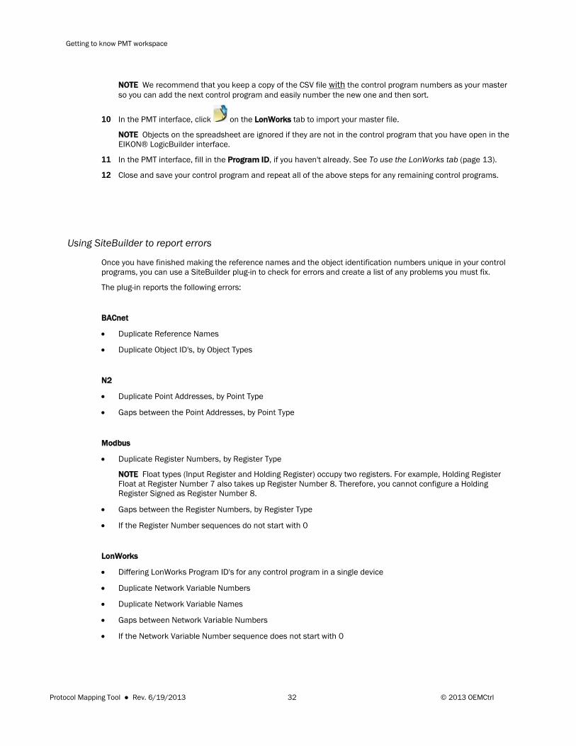
Using SiteBuilder to report errors
Once you have finished making the reference names and the object identification numbers unique in your control programs, you can use a SiteBuilder plug-in to check for errors and create a list of any problems you must fix.
The plug-in reports the following errors:
BACnet
• Duplicate Reference Names
• Duplicate Object ID's, by Object Types
N2
• Duplicate Point Addresses, by Point Type
• Gaps between the Point Addresses, by Point Type
Modbus
• Duplicate Register Numbers, by Register Type
NOTE Float types (Input Register and Holding Register) occupy two registers. For example, Holding Register Float at Register Number 7 also takes up Register Number 8. Therefore, you cannot configure a Holding Register Signed as Register Number 8.
• Gaps between the Register Numbers, by Register Type
• If the Register Number sequences do not start with 0
LonWorks
• Differing LonWorks Program ID's for any control program in a single device
• Duplicate Network Variable Numbers
• Duplicate Network Variable Names
• Gaps between Network Variable Numbers
• If the Network Variable Number sequence does not start with 0
Protocol Mapping Tool ● Rev. 6/19/2013 32 © 2013 OEMCtrl
Getting to know PMT workspace
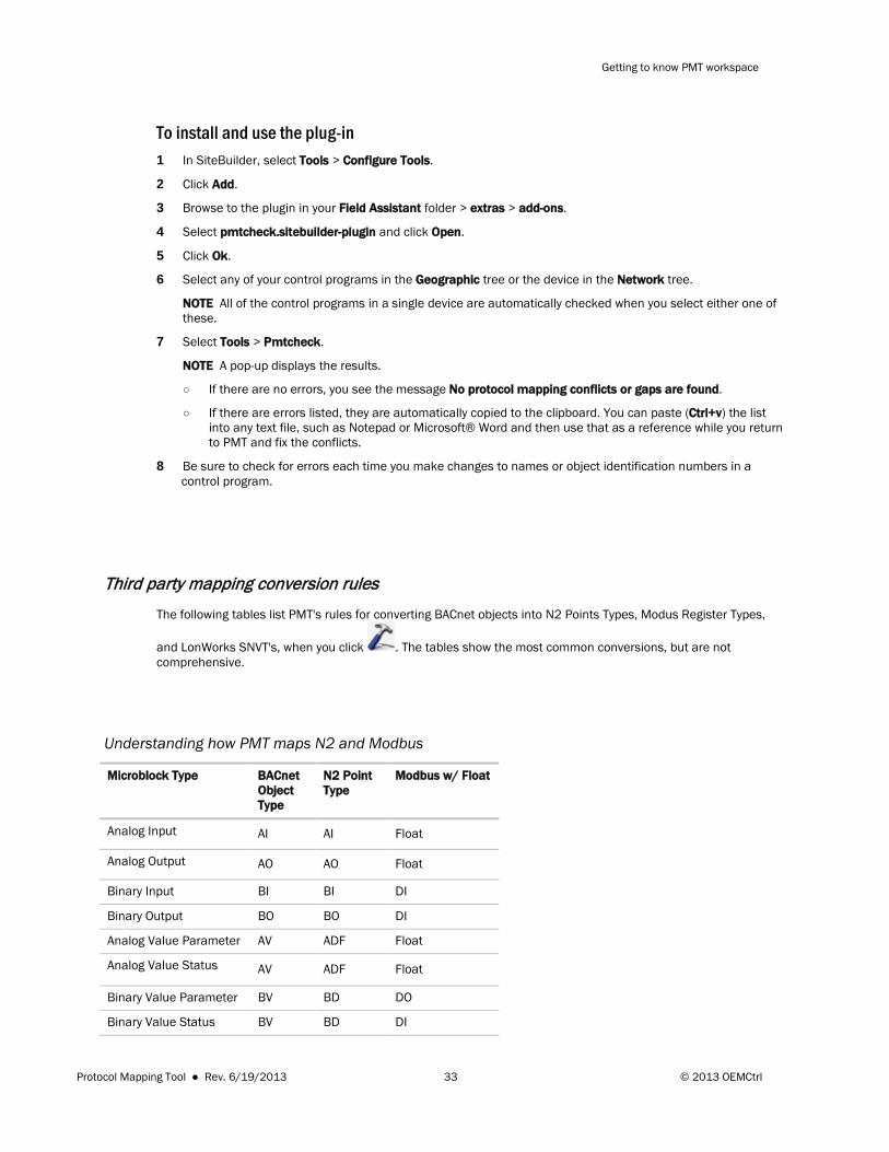
To install and use the plug-in 1 In SiteBuilder, select Tools > Configure Tools.
2 Click Add.
3 Browse to the plugin in your Field Assistant folder > extras > add-ons.
4 Select pmtcheck.sitebuilder-plugin and click Open.
5 Click Ok.
6 Select any of your control programs in the Geographic tree or the device in the Network tree.
NOTE All of the control programs in a single device are automatically checked when you select either one of these.
7 Select Tools > Pmtcheck.
NOTE A pop-up displays the results.
○ If there are no errors, you see the message No protocol mapping conflicts or gaps are found.
○ If there are errors listed, they are automatically copied to the clipboard. You can paste (Ctrl+v) the list into any text file, such as Notepad or Microsoft® Word and then use that as a reference while you return to PMT and fix the conflicts.
8 Be sure to check for errors each time you make changes to names or object identification numbers in a control program.
Third party mapping conversion rules The following tables list PMT's rules for converting BACnet objects into N2 Points Types, Modus Register Types,
and LonWorks SNVT's, when you click . The tables show the most common conversions, but are not comprehensive.
Understanding how PMT maps N2 and Modbus
Microblock Type BACnet Object Type
N2 Point Type
Modbus w/ Float
Analog Input AI AI Float
Analog Output AO AO Float
Binary Input BI BI DI
Binary Output BO BO DI
Analog Value Parameter AV ADF Float
Analog Value Status AV ADF Float
Binary Value Parameter BV BD DO
Binary Value Status BV BD DI
Protocol Mapping Tool ● Rev. 6/19/2013 33 © 2013 OEMCtrl
Getting to know PMT workspace
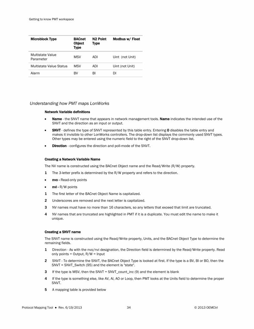
Microblock Type BACnet Object Type
N2 Point Type
Modbus w/ Float
Multistate Value Parameter MSV ADI Uint (not Unit)
Multistate Value Status MSV ADI Uint (not Unit)
Alarm BV BI DI
Understanding how PMT maps LonWorks
Network Variable definitions
• Name - the SNVT name that appears in network management tools. Name indicates the intended use of the SNVT and the direction as an input or output.
• SNVT - defines the type of SNVT represented by this table entry. Entering 0 disables the table entry and makes it invisible to other LonWorks controllers. The drop-down list displays the commonly used SNVT types. Other types may be entered using the numeric field to the right of the SNVT drop-down list.
• Direction - configures the direction and poll-mode of the SNVT.
Creating a Network Variable Name
The NV name is constructed using the BACnet Object name and the Read/Write (R/W) property.
1 The 3-letter prefix is determined by the R/W property and refers to the direction.
• nvo - Read-only points
• nvi - R/W points
1 The first letter of the BACnet Object Name is capitalized.
2 Underscores are removed and the next letter is capitalized.
3 NV names must have no more than 16 characters, so any letters that exceed that limit are truncated.
4 NV names that are truncated are highlighted in PMT if it is a duplicate. You must edit the name to make it unique.
Creating a SNVT name
The SNVT name is constructed using the Read/Write property, Units, and the BACnet Object Type to determine the remaining fields.
1 Direction - As with the nvo/nvi designation, the Direction field is determined by the Read/Write property. Read only points = Output, R/W = Input
2 SNVT - To determine the SNVT, the BACnet Object Type is looked at first. If the type is a BV, BI or BO, then the SNVT = SNVT_Switch (95) and the element is "state".
3 If the type is MSV, then the SNVT = SNVT_count_inc (9) and the element is blank
4 If the type is something else, like AV, AI, AO or Loop, then PMT looks at the Units field to determine the proper SNVT.
5 A mapping table is provided below
Protocol Mapping Tool ● Rev. 6/19/2013 34 © 2013 OEMCtrl
Getting to know PMT workspace
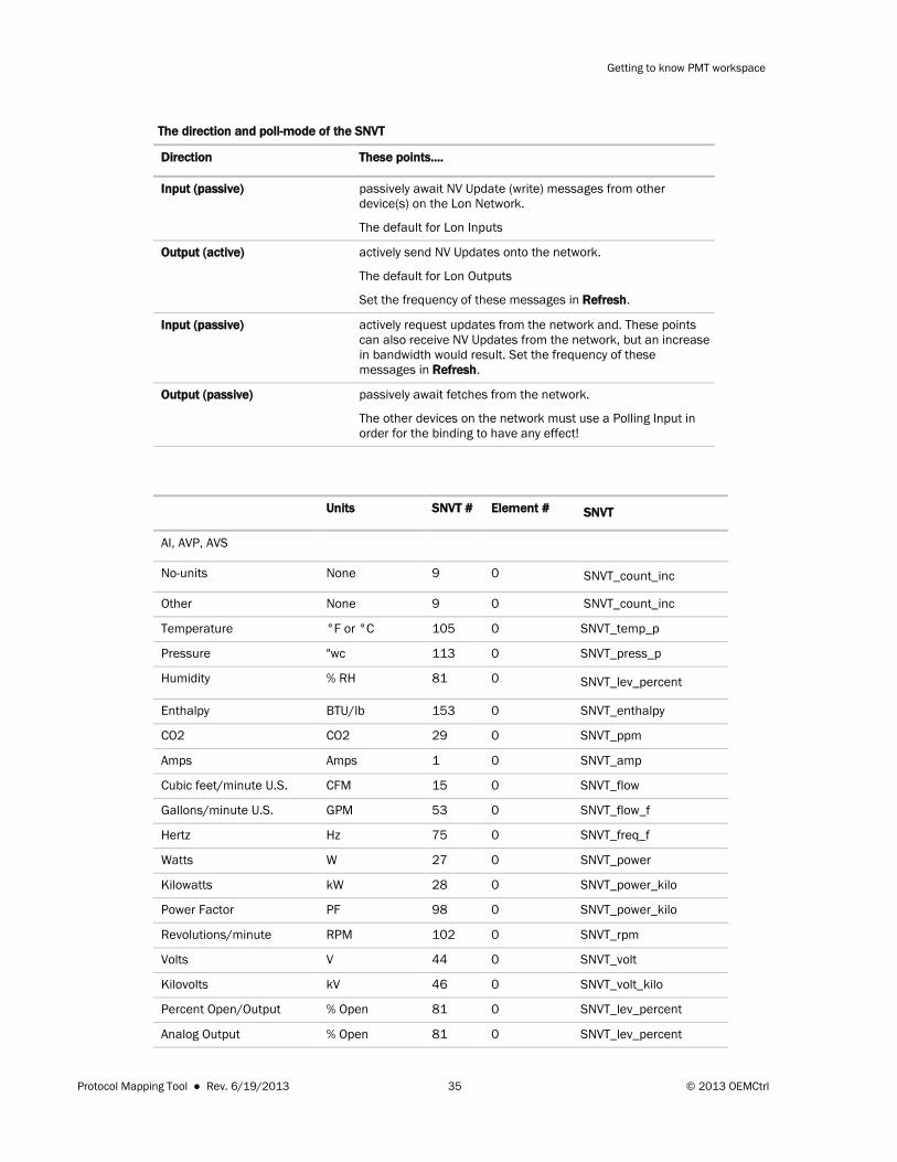
The direction and poll-mode of the SNVT
Direction These points....
Input (passive)
passively await NV Update (write) messages from other device(s) on the Lon Network.
The default for Lon Inputs
Output (active)
actively send NV Updates onto the network.
The default for Lon Outputs
Set the frequency of these messages in Refresh.
Input (passive) actively request updates from the network and. These points can also receive NV Updates from the network, but an increase in bandwidth would result. Set the frequency of these messages in Refresh.
Output (passive) passively await fetches from the network.
The other devices on the network must use a Polling Input in order for the binding to have any effect!
Units SNVT # Element # SNVT
AI, AVP, AVS
No-units None 9 0 SNVT_count_inc
Other None 9 0 SNVT_count_inc
Temperature °F or °C 105 0 SNVT_temp_p
Pressure "wc 113 0 SNVT_press_p
Humidity % RH 81 0 SNVT_lev_percent
Enthalpy BTU/lb 153 0 SNVT_enthalpy
CO2 CO2 29 0 SNVT_ppm
Amps Amps 1 0 SNVT_amp
Cubic feet/minute U.S. CFM 15 0 SNVT_flow
Gallons/minute U.S. GPM 53 0 SNVT_flow_f
Hertz Hz 75 0 SNVT_freq_f
Watts W 27 0 SNVT_power
Kilowatts kW 28 0 SNVT_power_kilo
Power Factor PF 98 0 SNVT_power_kilo
Revolutions/minute RPM 102 0 SNVT_rpm
Volts V 44 0 SNVT_volt
Kilovolts kV 46 0 SNVT_volt_kilo
Percent Open/Output % Open 81 0 SNVT_lev_percent
Analog Output % Open 81 0 SNVT_lev_percent
Protocol Mapping Tool ● Rev. 6/19/2013 35 © 2013 OEMCtrl
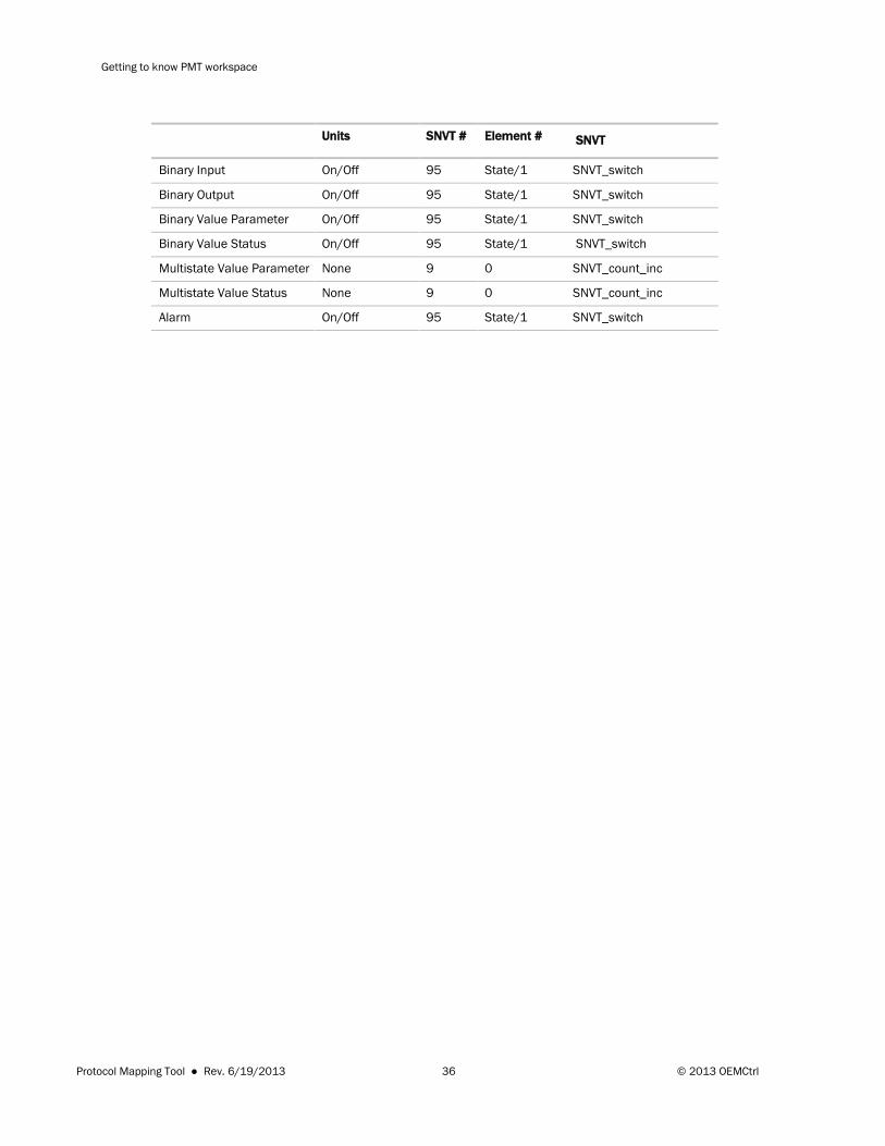
Getting to know PMT workspace
Units SNVT # Element # SNVT
Binary Input On/Off 95 State/1 SNVT_switch
Binary Output On/Off 95 State/1 SNVT_switch
Binary Value Parameter On/Off 95 State/1 SNVT_switch
Binary Value Status On/Off 95 State/1 SNVT_switch
Multistate Value Parameter None 9 0 SNVT_count_inc
Multistate Value Status None 9 0 SNVT_count_inc
Alarm On/Off 95 State/1 SNVT_switch
Protocol Mapping Tool ● Rev. 6/19/2013 36 © 2013 OEMCtrl


OEMCtrl® · 1025 Cobb Place Blvd, Kennesaw, GA 30144 · 770-429-3060 · www.oemctrl.com
6/19/2013