protocol: labstock high density fermentation and extract
TRANSCRIPT

High Density Fermentation and Extract Preparation Protocol - Page 1
Protocol: Labstock High Density Fermentation
and Extract Preparation
Procedure for growing E. coli strain KC6 (A19 met+, tonA, tnaA, speA, endA, sdaA, sdaB, gshA) in the
B.Braun 10 L Biostat C fermentor. KC6 specific growth rate is approximately 0.8-1.0 /hr. This procedure can also
be adapted for other E. coli strains, such as the commercially-available BL21(DE3) with or without IPTG induction.
The specific growth rate that we have observed for BL21 is approximately 0.6 /hr.
Overview Day 1 - Setup Day 2 - Fermentation Day 3 - Extract Prep
Media Preparation.
pH Probe Calibration.
Shake Flask and Fermentor Setup.
Fermentor Sterilization.
Feed/Stock solution preparation.
Feed Equipment Assembling.
Overnight Flask Inoculation.
Inoculation Flask Inoculation.
Final Feed Equipment Setup.
Computer Setup.
Pumps Calibration.
Fermentor pH Adjustment.
PO2 probe Calibration.
Inoculation.
Fermentation.
Harvesting and Shutdown.
Cell Washes.
Clean up.
Homogenization.
Extract Dialysis.
DAY 1
1. Media Preparation
1) Autoclave 8L of MQ water. When finished place it on ice until it is cool enough to place in the 4C dairy case
for later use. Note: This will be used to prepare S30 buffer for cell washing steps.
2) Make defined media (see attached sheets).
a) Add the five salts (powders) to a 2L flask with a large stir bar.
Fermentor Media Salts
Reagents Supplier Cat. No. Lot No. Required (g) Actual (g)
(NH4)2SO4 Sigma A3920 12
KH2PO4 Sigma P5379 24
K2HPO4•3(H2O) Sigma P5504 48
Na3citrate•2(H2O) Mallinckrodt 0734 4
KCl Sigma P9541 8
Table 1. Fermentor Salts
b) Add MQ water up to about 1L.
c) Take the flask to the sterile hood. With the pipet gun, add the Fe, Mo, and trace metals solutions (which
have been sterile filtered). Use the attached preparation sheet to create these solutions if it has not already
been done.
Add to Salts
Reagents Lot No. Required (mL) Actual (mL)
FeCl3 stock 32
Mo stock 2
Metals stock 2.4
Table 2. Fermentor Metals.
High Density Fermentation and Extract Preparation Protocol - Page 2
d) Return the flask to a stir plate. Stir until all the powders have dissolved.
e) Put aside during fermentor setup.
Note: Take note of the total volume of salt solution prepared as this information will be needed when
adding up the fermentor volume with water to 7.2L.
2. pH Probe Calibration
3) Setup fermentor for sterilization.
a) Drain the fermentor.
i) Take the cap off the drain below the fermentor, the exit port that points directly outwards. Place the
white bucket beneath the drain.
ii) Open the bottom drain valve (black knob).
Note: This valve is opened when the dial moves away from the base of the fermentor and closes when
the dial moves towards the base of the fermentor.
iii) To expedite draining, loosen or open one of the top ports to allow air in.
b) Once the fermentor has been drained, close the top port.
c) Make sure the sampling port is closed (latch is perpendicular to port exit).
d) Make sure each of the top ports have a good septum installed.
Note: A good septum, if pierced should re-seal. Replacement septums can be found in the drawer under the
Bioflow fermentor.
e) Turn on the fermentor control box by turning the red knob to the vertical, on position.
f) Calibrate the pH probe.
i) Press the “calibration” key on the main control panel until the pH screen is reached.
ii) Place the pH probe in the pH7.0 buffer. Use the arrow keys to move to the “BUFZ” line. Hit enter.
The cursor should move to “ok”. When the pH7 calibration is complete, the cursor will automatically
move to the next line.
Note: Although not recommended, the system can be forced to accept a calibration point by pressing
“enter” before the system automatically determines the calibration point. If a calibration point is forced
by the user, check that the calibration points are within range before proceeding.
iii) Rinse the pH probe with MQ water.
Note: Do not dry the probe.
iv) Place the pH probe in the pH4.0 buffer. Make sure the cursor is at “BUFS”. Hit enter. The cursor
should move to “ok”. When the pH4 calibration is complete, the cursor will automatically move to the
next line (RECAL) automatically.
v) Insert the pH probe into one of the lower side-entry ports on the right side of the fermentor.
g) Inspect the DO probe
i) Remove the green probe-tip protector cap.
ii) Make sure the membrane is not torn
iii) Press the “Process Values” button on the main control panel. The DO probe reading is shown on the
fourth line: “pO2”.
iv) Blow on the membrane and watch the reading as it increases slightly and then fall.
v) If the DO probe does not look good, refill it with electrolyte or change the membrane.
Note: See the users’ manual on how to change the membrane or refill the probe with electrolyte.
h) Insert the DO probe into one of the lower right-side entry ports.
High Density Fermentation and Extract Preparation Protocol - Page 3
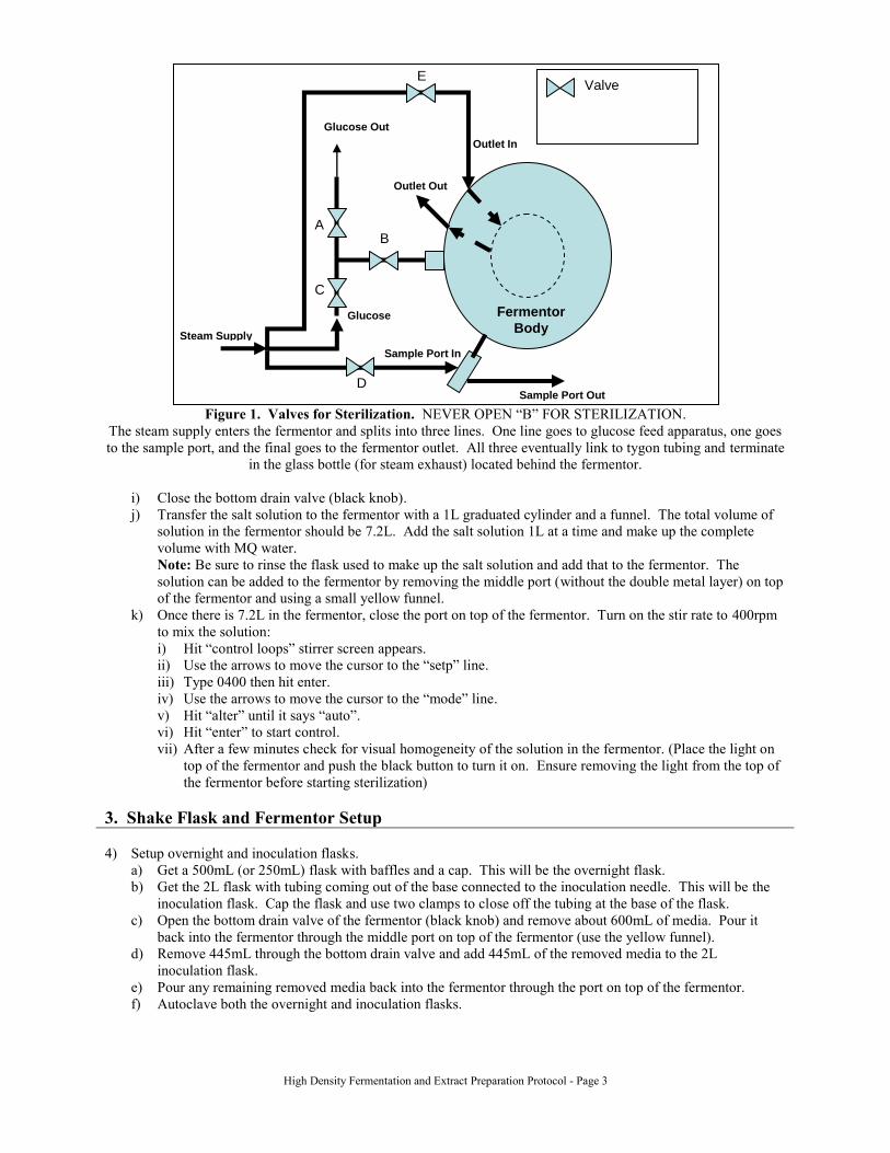
Figure 1. Valves for Sterilization. NEVER OPEN “B” FOR STERILIZATION.
The steam supply enters the fermentor and splits into three lines. One line goes to glucose feed apparatus, one goes
to the sample port, and the final goes to the fermentor outlet. All three eventually link to tygon tubing and terminate
in the glass bottle (for steam exhaust) located behind the fermentor.
i) Close the bottom drain valve (black knob).
j) Transfer the salt solution to the fermentor with a 1L graduated cylinder and a funnel. The total volume of
solution in the fermentor should be 7.2L. Add the salt solution 1L at a time and make up the complete
volume with MQ water.
Note: Be sure to rinse the flask used to make up the salt solution and add that to the fermentor. The
solution can be added to the fermentor by removing the middle port (without the double metal layer) on top
of the fermentor and using a small yellow funnel.
k) Once there is 7.2L in the fermentor, close the port on top of the fermentor. Turn on the stir rate to 400rpm
to mix the solution:
i) Hit “control loops” stirrer screen appears.
ii) Use the arrows to move the cursor to the “setp” line.
iii) Type 0400 then hit enter.
iv) Use the arrows to move the cursor to the “mode” line.
v) Hit “alter” until it says “auto”.
vi) Hit “enter” to start control.
vii) After a few minutes check for visual homogeneity of the solution in the fermentor. (Place the light on
top of the fermentor and push the black button to turn it on. Ensure removing the light from the top of
the fermentor before starting sterilization)
3. Shake Flask and Fermentor Setup
4) Setup overnight and inoculation flasks.
a) Get a 500mL (or 250mL) flask with baffles and a cap. This will be the overnight flask.
b) Get the 2L flask with tubing coming out of the base connected to the inoculation needle. This will be the
inoculation flask. Cap the flask and use two clamps to close off the tubing at the base of the flask.
c) Open the bottom drain valve of the fermentor (black knob) and remove about 600mL of media. Pour it
back into the fermentor through the middle port on top of the fermentor (use the yellow funnel).
d) Remove 445mL through the bottom drain valve and add 445mL of the removed media to the 2L
inoculation flask.
e) Pour any remaining removed media back into the fermentor through the port on top of the fermentor.
f) Autoclave both the overnight and inoculation flasks.
Steam Supply
Glucose Out
Sample Port Out
Outlet Out
Outlet In
Sample Port In
Glucose In
Fermentor
Body
C
A B
D
E Valve
High Density Fermentation and Extract Preparation Protocol - Page 4
4. Fermentor Sterilization
5) Sterilize the fermentor.
a) Add 1mL of Antifoam 289 (or Antifoam 204) to the fermentor through a top port using a 5 or 10mL pipet.
Make sure to place the tip into the media and pipet in and out repeatedly to get all of the Antifoam into the
media. The antifoam will make the culture media turn cloudy at 37° C. Media will regain clarity when it
cools to room temperature.
Note: Either antifoam is fine. Make sure that fermentor agitation is off when adding the antifoam.
b) Close and make sure that all ports on the top and on the sides of the fermentor are firmly hand tightened.
c) Turn on the main air, water, and steam supply valves (on the wall). Turn each knob to the fully open
position, then back ¼ turn.
Note: The water and steam knobs are labeled; the air knob is to the left and faces upwards.
i) Check the air supply pressure valve on the back of the fermentor it should read about 2.0 to 2.5bar (lift
knob above the gauge and turn to adjust if needed). Turn right to tighten, left to loosen.
ii) Check the cooling water supply pressure valve on the back of the fermentor it should read about 0.5bar
(see Page 3-7 in the manual for formal filling instructions).
Note: The water supply pressure can be increased by performing the following. Locate the water
supply inlet and outlet valves. They are black knobs that run from the silver water column (w/ P-
gauge) at the top back of the fermentor. The top knob is the outlet valve and the bottom valve is the
inlet valve. Open the inlet valve all the way. Open the outlet valve all the way. Let the water run for
about 5 minutes. Close the outlet valve. Close the inlet valve. After the temperature setpoint for the
fermentor has been set and turned on, listen for clicking/metal-scratching on metal sounds coming
from behind the fermentor. This either indicates that the water loop was not properly primed or that
one of the steam or water source were not turned on. If the water loop is not properly primed/filled, the
sterilization temperature will not reach 121C.
d) Turn off the E-Gas sampling valve. Follow the green line from the EGAS-1 unit to a green valve. Close
this valve.
Note: This valve should already be closed. However, to close these types of valves, turn the valve until the
handle is perpendicular to the direction of flow. To open, turn the valve until the handle is parallel to the
direction of flow.
e) Turn off the water flow to the condenser. Follow the red line coming from the bottom of the condenser.
The red line terminates at a green valve. Close this valve.
f) Take the light off the top of the fermentor if not already done.
g) Raise the Air Inlet to the “Ster.” position.
h) Make sure that the relief valve is closed.
Note: It is the black knob on the fermentor with a black ball at the end. To close the valve, turn the nob
until it is loose. To open the valve, turn the knob so that it rides down the screw. The black ball at the end
can also be pulled to temporarily relieve pressure.
i) Set the air flow to 4SLPM on the control panel, by using the ‘control loop’ button.
Note: The air flow can be set to 10SLPM allowing the fermentor to reach the desired pressure in next step.
Return the air flow to 4SLPM when the next step is completed.
j) Adjust the back-regulator to set the fermentor pressure to 0.8bar (between 0.2 to 1.0bar) by adjusting the
blue knob to the right of the fermentor. The backpressure gauge is located on top of the fermentor, behind
the agitator motor.
Notes:
Pressurizing the fermentor prevents contamination caused by leaks. Pressuring the fermentor
above 1.0bar can lead to feed issues and can also limit the inlet air flow rate.
Make sure there are no air leaks by squeezing water on top of the fermentor. If one of the top
ports, relief valve, or pressure gauge bubbles, then remove and put Teflon tape on the threads.
If air does not flow into the fermentor (setp is 4 SLPM, but air in is 0.3 SLPM), check the air filter
on top of the condenser. If it is too wet, it will clog, and air will be unable to enter the fermentor.
Check to see if the fermentor holds pressure before beginning sterilization. Squirt MQ water
around the major ports and inlets on top of the fermentor. Inspect the port seams for air bubbling
out. If air bubbles out, exhaust the fermentor and add Teflon tape to the threading to enhance the
seal. If that doesn’t work, then you must change the fittings’ o-rings.
k) Set the fermentor temperature to 37C on the control panel, by using the ‘control loop’ button. Wait for the
fermentor to reach 37C before proceeding with the sterilization.
Note: When fermentor temperature control is turned on, the red centrifugal pump on the back of the
fermentor should start running. While running, a mild water-splashing sound should be heard. If not the

High Density Fermentation and Extract Preparation Protocol - Page 5
pump may not be circulating water as it should be. After turning on the temperature control to 37C monitor
the water supply pressure gauge located at the top of the water column. If over a couple of seconds the
pressure rises >1.0bar, this indicates that gas is trapped in the water loop/circulation line (vapor lock). The
line must therefore be purged of the gases. This can be done by repriming/refilling the water loop or by
removing and reattaching the pump (the latter is not recommended unless problems persist).
l) On the control box press the “Sterilization” button and move the cursor to the “Mode” line.
m) Press “Alter” until “Start” is displayed, then press “Enter”. The fermentor will then begin purging liquid
into the adjacent drain basin on the floor. This is normal.
Note: When the fermentor begins sterilization, the air flow to the fermentor will automatically be shut off.
The pressure in the fermentor will drop to ~0bar. When the temperature reaches 100C, the fermentor media
will begin boiling. However, a valve controlling fermentor pressure will automatically close and the
fermentor pressure should rise and exceed 2bar to sterilize without the media to boil. Once the complete
sterilization cycle has been finished, the fermentor will automatically restart the air flow. If the sterilization
is manually halted prior to completion, complete the following steps. The fermentor will automatically start
the fermentor cooling process. Wait until the temperature of the fermentor reaches 37°C, then restart the
sterilization process again.
n) When the fermentor reaches sterilization temperature (121°C, about 50mins after starting), sterilize the
sample line, harvest line, and glucose feeding apparatus for 15min.
Note: At this point, proceed with Day 1, Section 5 and Section 6 (steps 7 to 10) of the protocol as well as
autoclaving the necessary feed bottles (and return to this step once the fermentor has reached sterilization
temperature. Make sure to check on the fermentor periodically to check on the temperature. The operator
must be present when the fermentor reaches 121C to open the necessary valves during the 15min interval.
If the window is missed the sterilization needs to be restarted. If the fermentor seems incapable of reaching
121C, it is likely that the water loop was not properly filled. Either restart the sterilization after filling the
water loop or sterilize for 15min at no less than 115C. If this is the case, once complete, change the
sterilization setting to “stop”.
i) See Figure 1.
ii) Open Valve C to the glucose feed line.
iii) Open Valve A to allow the steam to exhaust from the glucose feed line and to sterilize the line.
iv) Open Valve D to sterilize the sampling port.
v) Open Valve E to sterilize the fermentor outlet port.
vi) After 15min, close all valves on the left side of the fermentor.
Note: Do not open Valve B.
Steam will then pass from the inlet through the glucose feeding apparatus/outlet/sample port to the glass jar
behind the fermentor. A great deal of steam will spew out in this process. This is normal.
o) When the sterilization cycle finishes, the control unit will beep and display a message. Press “Enter” to
acknowledge the message and to silence the alarm.
p) Open the exhaust water condenser valve so that during the cooling process, media is not evaporated.
q) If the fermentor is not going to be inoculated the same day, turn the stirrer and temperature controls off. To
prevent contamination keep the Air Inlet in the “Ster.” position and leave the airflow on to maintain
positive pressure (about 0.2 to 0.4 bar gauge) in the fermentor. Turn off the main water and steam supply
valves, but leave the air on. The fermentor can be left like this overnight.
Note: As added precautionary measure, the cooling water supply can be kept on and the fermentor
temperature can be set to sub-RT.
5. Feed/Stock Solution Preparation
6) Make glucose and amino acid stock and feed solutions.
a) Make 1L of 50%(w/v) glucose stock solution.
Note: Only 85mL is needed. Therefore, save any remaining for any fermentation that may be performed
within 1 to 2 months. Use good judgment when using older reagents.
Glucose Stock Solution
Reagent Supplier Cat. No. Lot No. Required (g) Actual (g)
Glucose Sigma G-8270 500
Table 2. Glucose Stock Solution.
i) Add 500mL MQ water to a 2L beaker.
ii) Heat the water in the microwave for 2 to 3min.

High Density Fermentation and Extract Preparation Protocol - Page 6
iii) Put a stir bar in the beaker and place the beaker on the heat plate. Turn on the stirrer.
iv) Weigh out 500g of glucose and slowly add it to the water.
Note: Adding too much glucose at once will stop the stir bar from mixing. Dissolution can be
facilitated by microwaving the solution again for 1 to 2min. Do not let the glucose solution get too hot
or it may turn yellowish.
v) After the glucose has dissolved, transfer the solution to a 1L graduated cylinder and fill up to 1L with
MQ water.
vi) Sterile filter the solution using a 1000mL, 0.2um PES filter bottle system.
vii) Label the solution and initial and date.
b) Make 1L of glucose feed solution: 50%(w/v) glucose with 18.9g MgSO4•7H2O
Glucose Feed Solution
Reagent Supplier Cat. No. Lot No. Required (g) Actual (g)
Glucose Sigma G-8270 500
MgSO4• 7 H2O Mallinckrodt 6066 18.9
Table 3. Glucose Feed Solution.
i) Add 500mL MQ water to a 2L beaker.
ii) Heat the water in the microwave for 2min.
iii) Put a stir bar in the beaker and place the beaker on the heat plate. Turn on the stirrer.
iv) Weigh out 500g of glucose and slowly add it to the water.
Note: Adding too much glucose at once will stop the stir bar from mixing. Dissolution can be
facilitated by microwaving the solution again for 1 to 2min. Do not let the glucose solution get too hot
or it may turn yellowish.
v) After the glucose has dissolved, add 18.9g MgSO4•7H2O
vi) Transfer the solution to a 1L graduated cylinder and fill up to 1L with MQ water.
vii) Sterile filter the solution using a 1000mL, 0.2um PES filter bottle system.
viii) Label the solution and initial and date.
c) Make 1L of amino acid stock solution
Amino Acid Stock Solution
Reagent Supplier Cat. No. Lot No. Required (g) Actual (g)
Asparagine H2O Sigma A4284 9.075
Glycine Sigma G7126 13.105
Histidine HCl H2O Sigma H8125 2.514
Isoleucine Ajinomoto N/A, 1KG R020E005 6.519
Leucine Sigma L8000 6.738
Lysine HCl Sigma L5625 5.720
Methionine Sigma M9625 2.614
Phenylalanine Sigma P2126 2.618
Proline Sigma P0380 8.700
Threonine Ajinomoto N/A, 1KG R730C001 6.888
Tryptophan Sigma T0254 2.648
Tyrosine Sigma T3754 3.204
Valine Sigma V0500 4.236
Betaine HCl Sigma B3501 6.144
KOH --- ---
Estimated pH 9.68 – 10.50
Final pH
Table 4. Amino Acid Stock Solution.
i) Place the heat/stir plate near the pH meter.
ii) Add 600mL MQ water to a 2L beaker.
iii) Put a stir bar in the beaker and place the beaker on the heat plate. Turn on the stirrer to create a vortex
while limiting splashing
High Density Fermentation and Extract Preparation Protocol - Page 7
iv) Submerge the calibrated pH probe just below the water surface. Make sure the stir bar does not hit the
probe.
v) Add the amino acid powders to the water in the order shown. After addition of each amino acid, check
the pH of the solution. Add KOH pellets between each amino acid to keep the pH around 12 to 13.
Make sure each amino acid dissolves before adding the next amino acid. When adding tryptophan
begin adding only enough KOH pellets to dissolve the amino acids. Limit the amount used at this point
to reach the target end pH.
Note: Tyrosine requires more time to dissolve. The final solution pH should be approximately 9.68 to
10.5. If the pH is above 9.68, more 9M H2SO4 will need to be added in a later step and should not
affect the fermentation yield. However, the pH should not exceed 11.
vi) Once all the amino acids have been added and are completely dissolved, transfer the solution to a 1L
graduated cylinder. Fill up to 1L with MQ water.
vii) Sterile filter the solution using a 0.2um PES filter bottle system..
viii) Label the solution and initial and date.
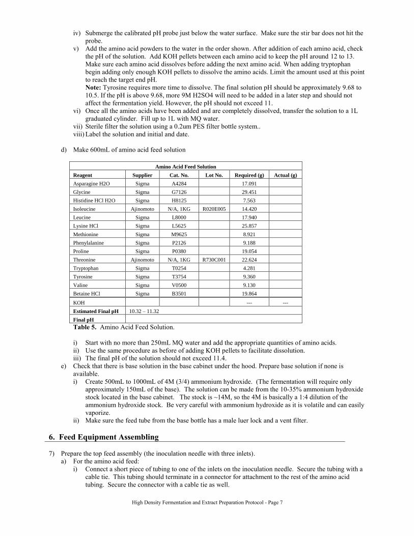
d) Make 600mL of amino acid feed solution
Amino Acid Feed Solution
Reagent Supplier Cat. No. Lot No. Required (g) Actual (g)
Asparagine H2O Sigma A4284 17.091
Glycine Sigma G7126 29.451
Histidine HCl H2O Sigma H8125 7.563
Isoleucine Ajinomoto N/A, 1KG R020E005 14.420
Leucine Sigma L8000 17.940
Lysine HCl Sigma L5625 25.857
Methionine Sigma M9625 8.921
Phenylalanine Sigma P2126 9.188
Proline Sigma P0380 19.054
Threonine Ajinomoto N/A, 1KG R730C001 22.624
Tryptophan Sigma T0254 4.281
Tyrosine Sigma T3754 9.360
Valine Sigma V0500 9.130
Betaine HCl Sigma B3501 19.864
KOH --- ---
Estimated Final pH 10.32 – 11.32
Final pH
Table 5. Amino Acid Feed Solution.
i) Start with no more than 250mL MQ water and add the appropriate quantities of amino acids.
ii) Use the same procedure as before of adding KOH pellets to facilitate dissolution.
iii) The final pH of the solution should not exceed 11.4.
e) Check that there is base solution in the base cabinet under the hood. Prepare base solution if none is
available.
i) Create 500mL to 1000mL of 4M (3/4) ammonium hydroxide. (The fermentation will require only
approximately 150mL of the base). The solution can be made from the 10-35% ammonium hydroxide
stock located in the base cabinet. The stock is ~14M, so the 4M is basically a 1:4 dilution of the
ammonium hydroxide stock. Be very careful with ammonium hydroxide as it is volatile and can easily
vaporize.
ii) Make sure the feed tube from the base bottle has a male luer lock and a vent filter.
6. Feed Equipment Assembling
7) Prepare the top feed assembly (the inoculation needle with three inlets).
a) For the amino acid feed:
i) Connect a short piece of tubing to one of the inlets on the inoculation needle. Secure the tubing with a
cable tie. This tubing should terminate in a connector for attachment to the rest of the amino acid
tubing. Secure the connector with a cable tie as well.

High Density Fermentation and Extract Preparation Protocol - Page 8
ii) Assemble the amino acid feed bottle and tubing:
(1) Prepare a 1L bottle to be autoclaved for the amino acid feed. This bottle should have a feed
assembly cap containing a line extending into the bottle and a vent line with filter.
(2) Attach the amino acid tubing to the line extending into the feed bottle. This tubing should contain
a T for attachment of a plastic pipet for calibration. Use 1/16” ID tubing (for fine control of the
flowrate).
iii) Cover all free ends of tubing (on the needle and on the bottle) with foil.
b) Base Feed Setup.
i) Connect a line ending in a female leur lock to one of the inlets on the inoculation needle.
ii) Secure the line with a cable tie.
iii) Cover the luer lock with foil.
Important: Before opening the cap to the luer lock on the base bottle, untighten the lid to the base bottle to
release any pressure build-up from vaporized ammonia. While the lid is still loose, open the cap to the luer
lock and fasten it to the connection on the inoculation/feed needle. Retighten the lid of the base bottle.
c) Post Sterilization setup.
i) Connect a short piece of tubing to the third inlet on the inoculation needle. Secure the line with a cable
tie. Cover the free end with foil.
ii) Prepare an empty 500mL bottle to be autoclaved for the post-sterilization additions. This bottle should
contain an outlet at the base to which a piece of tubing is connected. Make sure this tubing can
connect to the tubing on the inoculation needle. Secure the connector with a cable tie. Clamp this line
at the base of the bottle and cover the end with foil during autoclaving. Also cover the top of the bottle
with foil.
Figure 2. Amino Acid Feed Setup.
8) Prepare the glucose feed bottle (Figure 3)
a) Obtain an empty 1L bottle with a feeding assembly cap containing a line extending into the bottle and a
vent line with filter.
b) Assemble the glucose feed tubing. This tubing should terminate in a quick connect for attachment to the
glucose feeding apparatus. The tubing should also contain a T (on the feed side of the pump) for
attachment of a plastic pipet for calibration.
c) Attach this tubing to the line extending into the feed bottle.
d) Cover the quick connect and all free ends with foil.
Figure 3. Glucose Feed Setup.
9) Autoclave the following materials:
(1) Inoculation flask (w/ ~445mL of fermentor batch salts).
(2) Amino Acid Feed Bottle with inoculation needle assembly (empty).
High Density Fermentation and Extract Preparation Protocol - Page 9
(3) Glucose Feed Bottle with quick-connect (empty).
(4) Post-sterilization bottle and attached tubing (empty).
(5) Base Feed Bottle (empty).
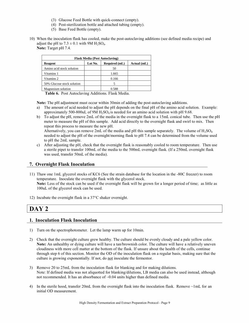
10) When the inoculation flask has cooled, make the post-autoclaving additions (see defined media recipe) and
adjust the pH to 7.3 ± 0.1 with 9M H2SO4.
Note: Target pH 7.4.
Flask Media (Post Autoclaving)
Reagent Lot No. Required (mL) Actual (mL)
Amino acid stock solution 50
Vitamins 1 1.665
Vitamins 2 0.166
50% Glucose stock solution 5
Magnesium solution 0.588
Table 6. Post Autoclaving Additions. Flask Media.
Note: The pH adjustment must occur within 30min of adding the post-autoclaving additions.
a) The amount of acid needed to adjust the pH depends on the final pH of the amino acid solution. Example:
approximately 500-800uL of 9M H2SO4 is needed for an amino acid solution with pH 9.68.
b) To adjust the pH, remove 2mL of the media in the overnight flask to a 15mL conical tube. Then use the pH
meter to measure the pH of this sample. Add acid directly to the overnight flask and swirl to mix. Then
repeat this process to measure the new pH.
Alternatively, you can remove 2mL of the media and pH this sample separately. The volume of H2SO4
needed to adjust the pH of the overnight/morning flask to pH 7.4 can be determined from the volume used
to pH the 2mL sample.
c) After adjusting the pH, check that the overnight flask is reasonably cooled to room temperature. Then use
a sterile pipet to transfer 100mL of the media to the 500mL overnight flask. (If a 250mL overnight flask
was used, transfer 50mL of the media).
7. Overnight Flask Inoculation
11) Thaw one 1mL glycerol stocks of KC6 (See the strain database for the location in the -80C freezer) to room
temperature. Inoculate the overnight flask with the glycerol stock.
Note: Less of the stock can be used if the overnight flask will be grown for a longer period of time; as little as
100uL of the glycerol stock can be used.
12) Incubate the overnight flask in a 37°C shaker overnight.
DAY 2
1. Inoculation Flask Inoculation
1) Turn on the spectrophotometer. Let the lamp warm up for 10min.
2) Check that the overnight culture grew healthy. The culture should be evenly cloudy and a pale yellow color.
Note: An unhealthy or dying culture will have a tan/brownish color. The culture will have a relatively uneven
cloudiness with more cell matter at the bottom of the flask. If unsure about the health of the cells, continue
through step 6 of this section. Monitor the OD of the inoculation flask on a regular basis, making sure that the
culture is growing exponentially. If not, do not inoculate the fermentor.
3) Remove 20 to 25mL from the inoculation flask for blanking and for making dilutions.
Note: If defined media was not aliquotted for blanking/dilutions, LB media can also be used instead, although
not recommended. It has an absorbance of ~0.04 units higher than defined media.
4) In the sterile hood, transfer 20mL from the overnight flask into the inoculation flask. Remove ~1mL for an
initial OD measurement.

High Density Fermentation and Extract Preparation Protocol - Page 10
5) Incubate/shake the flask at 37°C, 280rpm. Use cable ties to secure the inoculation needle assembly so it doesn’t
roll around in the shaker.
6) Take a 1mL sample in a plastic cuvette and measure the initial OD600 and note the time on the datasheet.
Note: The accuracy of the spectrophotometer reading is most accurate between 0.1 to 0.5OD. If the sample OD
is outside this range, then perform the necessary dilutions to obtain an accurate reading.
2. Final Feed Equipment Setup Note: The following steps need to be completed before the inoculum OD reaches 2 to 4.
7) Turn on the water and steam supplies for the fermentor (on the wall). Turn each knob to the open position, then
¼ turn back.
Note: The steam supply should read ~40psig.
8) Check that the airflow is still 4SLPM.
9) Turn on the temperature control to check that the setting is 37°C.
10) Set the stirring rate to 100 RPM.
11) Autoclave enough 1L, 500mL and 200mL centrifuge bottles (for 7.2L) for the harvesting and centrifugation
step at the end of fermentation.
12) Prepare the post-sterilization additions for the fermentor in the sterile hood:
Fermentor Media (Post Sterilization)
Reagent Lot No. Required (mL) Actual (mL)
Vitamins 1 26.64
Vitamins 2 2.664
Amino acid stock solution 800
50% Glucose stock solution 80
Magnesium solution 9.44
Table 7. Post Sterilization. Fermentor Media.
a) Add vitamins 1 and vitamins 2 to the 500mL sterile addition bottle (see attached recipes)
b) Put 800mL of the stock amino acid solution into the amino acid feed bottle. This solution will be used to
calibrate the amino acid pump.
c) Put 80mL of the stock glucose solution and 9.44mL of the MgSO4 solution in the glucose feed bottle. This
solution will be used to calibrate the glucose pump.
13) Setup the feed pumps and ring stands.
a) Stack the two pumps on the cart next to the control box. Make sure both pumps are connected to power.
b) Connect the PS2-like data connector to the back of each pump. Make sure that the Amino acid data line is
connected to the Amino Acid pump and the Glucose data line is connected to the Glucose pump.
c) Place the ring stands on the cart between the pump and the fermentor.
14) Set up the Glucose feed.
a) Thread the tubing from the feed bottle through the glucose feed pump.
b) Clamp the line next to the pump on the fermentor side.
c) Remove the exhaust line on the glucose feed apparatus by disconnecting the quick-connect. Replace it with
the quick-connect attached to the glucose feed bottle.
d) Connect a sterile 10mL plastic pipet to the T in the tubing. Clamp the pipet to the ring stand.
e) Use the relief valve to vent the fermentor to atmospheric pressure.

High Density Fermentation and Extract Preparation Protocol - Page 11
f) Open the valves (A and X) from the glucose feed bottle to the fermentor. Make sure all other valves (C, D)
are closed.
Figure 4. Glucose Feed Setup.
15) Insert the top feed assembly (the needle with the three inlets).
a) Use the relief valve to vent the fermentor to atmospheric pressure.
b) Locate the port on the top of the fermentor that has a double metal layer. Remove the top metal cap. Keep
the grey septum in place.
c) Use ethanol and a match to flame sterilize the septum.
d) Insert the needle through the septum and tighten the nut.
e) Thread the tubing for the base feed through the base control pump on the control panel.
Note: The pump can run outside computer control by using the ‘Man.’ setting. Be sure to thread the tubing
in a direction such that the pump pushes liquid from the base bottle tothe fermentor.
f) Connect the base bottle to the base line (luer lock connection). Put the base bottle in the rack under the
control box.
g) Connect the amino acid bottle to the amino acid feed line on the top feed assembly.
h) Thread the tubing from the amino acid feed bottle through the amino acid feed pump.
i) Clamp the line next to the pump on the fermentor side.
j) Connect a sterile 10mL plastic pipet to the T in the amino acid feed tubing. Clamp the pipet to the ring
stand.
Figure 5. Amino Acid and Base Feed Setup.
16) Add the post-sterilization additions to the fermentor.
a) Use the relief valve to vent the fermentor to atmospheric pressure.
b) Attach the sterile addition bottle containing the vitamin solutions to the third inlet on the top feed assembly.
c) Unclamp the line and hold the bottle up high so that the vitamins drain into the fermentor.

High Density Fermentation and Extract Preparation Protocol - Page 12
Note: It may be necessary to turn down/off the air flow rate to get all the vitamin solution into the
fermentor.
d) Re-clamp the line close to the fermentor.
e) Detach the addition bottle and set it aside.
17) Close the safety valve to re-pressurize the fermentor. The backpressure reading should be approximately 0.4bar.
18) Turn on the condenser water flow by opening the green valve on the red line behind the fermentor.
19) Check that the backpressure on the fermentor is 1.5bar.
Note: The gauge is located on top of the fermentor behind the motor. The backpressure can be adjusted using
the blue knob below and to the right of the fermentor. The backpressure takes time respond, so adjust the knob a
periodically after it starts moving to determine the gauge response.
20) Set the airflow to 10SLPM.
Note: If the airflow rate reading does not reach 10SLPM, the air filter above the condenser can be removed or
the air supply pressure can be increased to 3.5bar using the black knob on the left behind the fermentor with the
1 to 4 bar scale. The above troubleshooting steps can be avoided by letting the air filter dry out completely after
sterilization.
3. Computer Setup
21) Setup the MATLAB glucose and amino acid feed program.
a) Get the Toshiba laptop computer and power cord. Make sure the DAQCard is inserted into the slot on the
left side of the computer marked “0”. Put the laptop on the desk next to the fermentor. Plug in the power.
b) Connect the feed pumps to the computer control cables making sure the “glucose” cable goes to the glucose
pump and the “AA” cable goes to the amino acid pump.
c) There should be a cable coming from a box on the wall next to the desk. Plug this cable into the DAQCard.
d) Check that both the glucose and amino acid pump s have been set to remote control. The switch is located
on the back of the pump.
e) Turn on the computer. Log in as “labuser” with the standard password. Open MATLAB 6.5.1 (the OLD
version).
f) Type in “glc_feed” in the MATLAB prompt. Hit “save” or “OK” at each prompt. Several windows should
open up. Wait for the program to say “complete”. If it does not say this, check that all three SQL services
are turned OFF when the OS starts (This can be checkedby clicking on the icon in the taskbar in the bottom
right of the screen). Then reconnect the cable to the DAQCard and restart the computer.
g) Type ‘go’ (with the quotation marks).
h) Change “glc feed” and “aa feed” to “manual” control. Set them both to “0”.
4. Pumps Calibration
22) Calibrate each pump separately
a) Make sure the pump tightness is set to 5.
b) Clamp the fermentor side of the T in the tubing.
Note: This is in addition to the clamp next to the pump.
c) Pull the solution into the 10mL pipet using a pipet gun.
d) Clamp the feed bottle side of the T. Unclamp the fermentor side of the T.
e) Check that the fermentor pressure does not push liquid back out of the fermentor into the pipet. Do this by
slowly releasing the clamp on the fermentor side of the pump and checking for flow back into the pipet.
Note: It is very important that this does not happen. If it does, this means that pump is not holding the
tubing tight enough and the calibration will not be performed properly. Therefore re-clamp the line near the
pump and try the following:
(1) Make sure the pump tightness settings are set to 5.
(2) Remove the line from the pump. Then reposition the line making sure that it lies in a straight line
through the pumping region.
(3) Then recheck for liquid movement.
f) Set the pump to “10” in the MATLAB control window.
g) Measure the amount of time it takes for 10mL of solution to be fed. Record this on the excel spreadsheet.
High Density Fermentation and Extract Preparation Protocol - Page 13
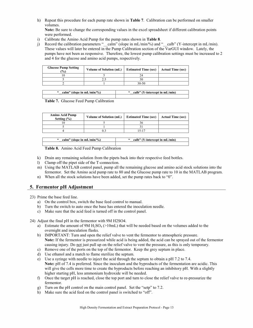
h) Repeat this procedure for each pump rate shown in Table 7. Calibration can be performed on smaller
volumes.
Note: Be sure to change the corresponding values in the excel spreadsheet if different calibration points
were performed.
i) Calibrate the Amino Acid Pump for the pump rates shown in Table 8.
j) Record the calibration parameters “__calm” (slope in mL/min/%) and “__calb” (Y-intercept in mL/min).
These values will later be entered in the Pump Calibration section of the VarGUI window. Lately, the
pumps have not been as responsive. Therefore, the lowest pump calibration settings must be increased to 2
and 4 for the glucose and amino acid pumps, respectively.
Glucose Pump Setting
(%) Volume of Solution (mL) Estimated Time (sec) Actual Time (sec)
10 5 24
5 2.5 30
2 1 30-50
“__calm” (slope in mL/min/%) “__calb” (Y-intercept in mL/min)
Table 7. Glucose Feed Pump Calibration
Amino Acid Pump
Setting (%) Volume of Solution (mL) Estimated Time (sec) Actual Time (sec)
10 5 36
5 1 31
4 0.3 15-17
“__calm” (slope in mL/min/%) “__calb” (Y-intercept in mL/min)
Table 8. Amino Acid Feed Pump Calibration
k) Drain any remaining solution from the pipets back into their respective feed bottles.
l) Clamp off the pipet side of the T-connection.
m) Using the MATLAB control panel, pump all the remaining glucose and amino acid stock solutions into the
fermentor. Set the Amino acid pump rate to 80 and the Glucose pump rate to 10 in the MATLAB program.
n) When all the stock solutions have been added, set the pump rates back to “0”.
5. Fermentor pH Adjustment
23) Prime the base feed line.
a) On the control box, switch the base feed control to manual.
b) Turn the switch to auto once the base has entered the inoculation needle.
c) Make sure that the acid feed is turned off in the control panel.
24) Adjust the final pH in the fermentor with 9M H2SO4.
a) Estimate the amount of 9M H2SO4 (>10mL) that will be needed based on the volumes added to the
overnight and inoculation flasks.
b) IMPORTANT: Turn and open the relief valve to vent the fermentor to atmospheric pressure.
Note: If the fermentor is pressurized while acid is being added, the acid can be sprayed out of the fermentor
causing injury. Do not just pull up on the relief valve to vent the pressure, as this is only temporary.
c) Remove one of the ports on the top of the fermentor. Keep the grey septum in place.
d) Use ethanol and a match to flame sterilize the septum.
e) Use a syringe with needle to inject the acid through the septum to obtain a pH 7.2 to 7.4.
Note: pH of 7.4 is preferred. Since the inoculum and the byproducts of the fermentation are acidic. This
will give the cells more time to create the byproducts before reaching an inhibitory pH. With a slightly
higher starting pH, less ammonium hydroxide will be needed.
f) Once the target pH is reached, close the top port and turn to close the relief valve to re-pressurize the
fermentor.
g) Turn on the pH control on the main control panel. Set the “setp” to 7.2.
h) Make sure the acid feed on the control panel is switched to “off”.

High Density Fermentation and Extract Preparation Protocol - Page 14
6. PO2 Probe Calibration
25) Let the fermentor sit at the correct temperature (37°C), air flow (10SLPM ) and backpressure (1.5bar gauge)
until each of the parameters has reached equilibrium for 10 minutes (measure the inoculum OD during this
time). Then calibrate the PO2 probe.
Note: The fermentor needs to be at its fermentation conditions for the calibration to work properly. The
fermentor will be controlled based on PO2 which is affected by these conditions along with the mixing rate.
i) Turn the stir rate to 600rpm.
ii) Set the 0% reading for the PO2 probe.
(1) Turn on the argon or nitrogen supply.
(a) There should be a tank located in front of the whiteboard behind the fermentor. This tank has
a line attached that leads to the fermentor. Turn on the tank by opening the main valve and the
small black knob.
(b) The green line coming out of the tank splits in two directions. Close the valve leading to the
hood and open the valve leading to the “10L fermentor”.
(c) Open the knob connecting the green line to the fermentor, the nitrogen supply. It is located on
the wall below the main air supply knob.
(2) Turn off the main air supply on the wall. The air supply knob near the floor seems to have a small
leak. To reach 0% O2, you must close the master air supply near the ceiling.
(3) Change the Air Inlet to the “Ferm.” Position.
(4) Move down to the “NITR” line. Make sure the reading is 0%. Press "Enter".
(5) Wait a couple of minutes, the control unit will accept the calibration when the reading is stable for
60 sec. FYI, recently, the 0% calibration has been taking upwards of 20 minutes.
Note: Although not recommended, in order to bypass or accept a calibration value, press "Enter"
when the cursor is on "ok" to force the unit to accept the reading.
iii) Set the 100% reading for the PO2 probe.
(1) Press “Calibration” until the PO2 screen appears.
(2) Turn off the nitrogen supply and turn on the air supply.
(3) Move down to the “AIR” line. Make sure the reading is 100%. Press "Enter".
Wait a couple of minutes. The control unit will accept the calibration when the reading is stable
for 60sec.
Note: Although not recommended, in order to bypass or accept a calibration value, press "Enter"
when the cursor is on "ok" to force the unit to accept the reading.
iv) Check the zero (0 to 15nA) and slope (25 to 200nA) for appropriate values. If the control box says that
the values are out-of-range, recalibrate the 0% and 100% points again. A typical zero ranges from 5-6
nA while a typical slope resides in the 150 nA range
Troubleshooting: If the zero point is calibrating higher than the acceptance range, check to see if there
is residual air flow to the fermentor. Do this by turning off both the air and the nitrogen source. Check
the flow meter on the back left of the fermentor support structure. If the ball in the gauge is bouncing,
then there is a possible air leak. Turn off the main air supply to the fermentor using the valve near the
ceiling above the fermentor and repeat the calibration.
Troubleshooting: During calibration of the ‘zero’ point, the control unit will still continue to
recognize changes even if the percent O2 level drops below 0. If this occurs, to gauge the DO probe
response, force the calibration to accept zeroes and monitor the corresponding change in the amperage
(nA) value.
Troubleshooting: If the calibration fails, the calibration can be repeated multiple times to get the
‘zero’ and ‘slope’ values into range. Calibration of each value occurs separately. Monitor the amperage
values to ensure they are not oscillating back to previous values. If this occurs, check the probe
functionality.
PO2/DO Probe disassembly: 1) Remove the black rubber ring on the back of the blue handle which
holds the wire in place, by pulling it away from the handle. 2) Unscrew the blue handle away from the
body of the probe. 3) Disconnect the cable from the probe body by turning the quick connect-like
system and pulling away from the probe body. 4) Unscrew the tip housing/protector to expose the
anode-cathode. 5) Refill the electrolyte solution into the tip housing/protector. 6) Rescrew the tip
housing. Some electrolyte will bead from the membrane as this is normal.

High Density Fermentation and Extract Preparation Protocol - Page 15
26) Add the Amino Acid feed and Glucose feed to their respective feed bottles.
a) Securely clamp off the line between each feed bottle and its pump.
b) Carefully unscrew each feed bottle. Without contaminating any of the feed lines add each feed solution into
their respective feed bottle. Once complete, close the bottles.
7. Inoculation
27) Measure the OD of the inoculation flask. Make sure the culture is growing in exponential phase by plotting the
growth curve. Try to target an OD between 2 and 4 for inoculation.
28) Turn and open the relief valve to vent the fermentor to atmospheric pressure.
29) Remove one of the ports on top of the fermentor and flame sterilize the grey septum. To do this, add a small
drop of 70% ethanol to the grey septum and light with a match.
30) Remove the inoculation flask from the incubator and remove the cap from the injection assembly.
31) Insert the inoculation needle through the septum and tighten the nut.
32) Restart the MATLAB program so that the zero time point will correspond to the inoculation time.
a) Shutdown the MATLAB control program by clicking on the “Exit Pump Control Program” button in the
bottom left corner of the VarGUI window. Close Matlab.
b) Restart MATLAB and type “glc_feed” in the MATLAB prompt. Wait for the program to say “Setup is
complete”.
c) Enter the calibration parameters – “__calm” (slope in mL/min/%) and “__calb” (Y-intercept in mL/min) –
for the glucose and amino acid feed pumps in the Pump Calibration section of the VarGUI window.
Remember to press return after each number entry.
d) Type in ‘go’ (with the single quotation marks) and hit return
Note: The pH, DO2, glucose feed, and amino acid feed graphs can be called up in order to monitor the
fermentation. The “glc feed” and “aa feed” should be set to “Auto.”
33) Hold the inoculation flask up above the fermentor and remove the tubing clamps to inoculate the fermentor.
34) Once all the inoculum has been added, remove the injection assembly and replace the steel plug over the
septum.
35) Turn and close the relief valve to re-pressurize the fermentor.
36) Take a sample to measure the initial OD in the fermentor
a) Place the big white bucket below the sampling port.
b) Open the sampling valve.
c) Drain about 20mL into the bucket.
d) Collect 5-10mL of fermentation product in a 15mL falcon tube.
e) Close the sampling port.
Note: Make sure that the sample port valve is firmly closed to prevent product loss.
37) Setup the amino acid feed solution.
a) Either, transfer (by pouring) the Amino Acid Feed Solution to the bottle that previously contained the
Amino Acid Stock Solution, or Transfer the cap from the stock bottle to the feed bottle.
Note: Perform this step quickly using sterile technique to minimize the chance of contamination. If the
amino acid feed solution is not completely dissolved, add the amino acid feed solution to the amino acid
feed bottle. Put the feed bottle on a heat plate (heat setting ~ 4) to redissolve the amino acids. Once all the
precipitate has dissolved, lower the heat to ~ 1. Check the pH of the solution. Small amount of KOH may
be added to facilitate dissolution.
38) Either, transfer (by pouring) the Glucose Feed Solution to the bottle that previously contained the Glucose
Stock Solution, or Transfer the cap from the stock bottle to the feed bottle.

High Density Fermentation and Extract Preparation Protocol - Page 16
Note: Perform this step quickly using sterile technique to minimize the chance of contamination.
39) Manually prime the glucose feed, amino acid feed, and base feed lines. Set each of the pumps to a manageable
pump rate and set the pumps to manual. Then turn on the pumps so that they pump in the correct direction.
Once complete turn off the pumps.
Note: The direction which the pumps are set to pump is dependent on how the tubing has been threaded.
40) Turn the switches on the back of the glucose and amino acid pumps to remote.
41) Turn on the pumps.
8. Fermentation
42) Half way through the fermentation (approximately 3-4 hours in) place the rotors for centrifugation step into the
centrifuges at 4C or into the 4C dairy case to cool.
43) Continue to take samples approximately once every hour. Record the OD on the fermentation spreadsheet.
44) The pO2 should drop over time.
Note: Recently, the pO2 has hovered near 100% even 2 hours into the fermentation. Since pO2 drop is more
sensitive at the lower values, we have been reducing fermentor backpressure to ~0.8bar to lower the pO2
reading. From here, we monitor the pO2 until it reaches 40%. Then, we increase fermentor backpressure to
1.5bar and monitor pO2 until it again reaches 40%. After it reaches 40%, we increase agitation to 1000rpm.
You must remember to disable the computer program’s glucose feed pulse test prior to making changes to pO2.
Otherwise, the program mistakes the jump in pO2 as a glucose limitation and starts the “soft landing” feeding.
The program begins pulse tests after a large pO2 spike (indicative of glucose limitation) or 3 hours, whichever
comes first. You turn off the pulse tests by setting “pO2_rise” and “pO2_drop” to “manual” with a value of
“0.” Return the settings to “auto” once the pO2 stabilizes after the perturbation.
45) Check that the amino acid pump is actually feeding amino acids.
Note: If the calculated pump speed is too low (i.e. the pump is not turning), then manually set the amino acid
feed rate to the smallest value with the pump moving. A typical glucose feed rate is 30mL/hr. Typical pump
speeds are 1.69 for the glucose pump and 3.19 for the amino acid pump.
A tell-tale sign of amino acid limitation is a change in E. coli metabolism, which can manifest itself as erratic
spikes in pO2 readings. If a cell needs to create an amino acid synthesis pathway, it will stop growing and
produce the necessary enzymes and precursors. Thus, pO2 should rise. If this is suspected, you can manually
feed amino acids to determine if this abolishes the pO2 spikes. If this does not, then there may be a glucose
limitation.
46) The glucose feeding computer program should not require much more attention. At three hours, the program
should start checking for sudden changes in PO2 (rise in calculated PO2 and PO2). When the initial
glucose is depleted, there will be a sudden, large sharp rise in PO2. When the program detects this rise in PO2,
it will beep and perform a glucose pulse test to start the glucose feeding. The glucose pulse test is used to
determine if the glucose in the fermentor has been depleted by evaluating the system response to a surge/pulse
in glucose. Once the pulse test is complete and glucose is being fed at the normal exponential rate
(“pulse.status” will be off). After a pulse test is observed, disable future pulses by switching the “po2_rise” and
“po2_drop” variables to manual mode and making sure their values are zero. The amino acid feed rate is fixed
relative to the glucose feed rate.
Note: Recently, the computer program has been malfunctioning and freezing. It often does not reach the point
where it feeds glucose and thus allows the culture to reach a glucose-limited state. A tell-tale sign of glucose
limitation is a large spike in pO2 or continuous small spikes of pO2. Should this occur, you can manually feed
glucose at a rate where the pO2 drops at an increasing rate. Growth should be exponential, which means
oxygen consumption should be exponential as well. You will need to fiddle around with the glucose feed rate
to keep the culture slightly above glucose limiting conditions. Feeding too much glucose will lead to acetate
accumulation.
47) When the PO2 falls to about 40%, increase the stir rate to 1000rpm.
a) Make sure a pulse test is not running (“pulse_test_running” = 0 in VarGUI)
b) Switch the the “po2_rise” and “po2_drop” variables in VarGUI to “manual” mode and set to them to zero

High Density Fermentation and Extract Preparation Protocol - Page 17
c) Right click on the STIRR controller in MFCS/win and change the setpoint in the window that appears.
Increase the stir rate to 1000rpm.
Note: If these two variables are not turned off, the system may perform a premature pulse test.
d) Once the PO2 is stable again, switch “po2_rise” and “po2_drop” back to auto mode.
48) Prepare the dialysis tubing and make 100x stocks of the S30 components:
a) Dialysis tubing:
i) Cut ten ~6in strips of the 50mm flat width 6000-8000 MWCO dialysis tubing.
ii) Soak it in MQ water for 2hrs.
iii) Change the MQ water and soak for another 2hrs.
iv) Change the MQ water and store the tubing in the 4°C.
b) Prepare S30, 100x stock solutions.
i) First check if S30 100x stocks have already been prepared. They are usually stored on the shelves just
to the left of the balances. If not, prepare each of the following solutions separately in MilliQ water and
sterile filter each through a 0.2um filter.
Note: 1000mL of each stock is needed for a single extract preparation. For 1.0 M Tris Acetate pH8.2
(dissolve the appropriate amount of Trizma Base powder and bring it to the correct pH using glacial
acetic acid). Less volume of each stock solution can be made if the dialysis portion of the protocol will
not be executed.
1M Tris-Acetate (pH 8.2)
Reagent Supplier Cat. No. Lot No. Required (g) Actual (g)
Trizma Base Sigma T6066 121.14
Glacial Acetic Acid EMD AX0073-9 NA NA
Dissolve Trizma in 250mL MQ water. Adjust pH to 8.2 with glacial acetic acid. Add up with MQ water to
1000mL total.
1.4M Mg(Acetate)2
Reagent Supplier Cat. No. Lot No. Required (g) Actual (g)
Mg(Acetate)2 Tetrahydrate Sigma 228648 300.16
Dissolve in 250mL MQ water. Add up with MQ water to 1000mL total using a graduated cylinder.
6.0M K(Acetate)
Reagent Supplier Cat. No. Lot No. Required (g) Actual (g)
K(Acetate) Mallinckrodt 6700 588.90
Dissolve in 250mL MQ water. Add up with MQ water to 1000mL total using a graduated cylinder.
Table 9. S30 Buffer 100x Stock Solutions.
9. Harvesting and Shutdown
49) Once enough OD readings have been taken, use the growth curve to anticipate when the fermentation will reach
OD 35.
50) About 1 to 2hrs before harvest, start stockpiling ice in large styrofoam containers with lids. Also put the 1L
centrifuge rotor in the 4°C fridge.
51) About 30min before harvest, put the large metal cooling coil in a plastic bin and cover it with ice.
Note: The bin of ice can be placed on a chair or cart for better access to the fermentor and to limit stress on the
pump. Try to keep the bin level.
52) In a separate bin, put the 1L centrifuge bottles on ice.
53) The coil should have plastic tubing attached to both ends. On one side the tubing leads to a Y followed by a
long metal straw which later will be inserted into the top of the fermentor. The tubing on the other side of the
coil will connect to the drain.

High Density Fermentation and Extract Preparation Protocol - Page 18
Figure 6. Harvester Setup
a) Attach the plastic tubing extending from the metal coil to the drain on the fermentor. Secure it with cable
ties.
b) Use two clamps to close off the side of the Y that does not feed back into the fermentor.
Note: This is done so that the cell solution can be cooled in the recirculation loop in the following steps.
54) When the fermentor has reached OD 35, begin the harvest.
a) Open the relief valve to vent the fermentor to atmospheric pressure.
b) Turn off the agitation.
c) Remove a port and septum from the top of the fermentor. Insert the metal dip tube and screw it in place.
Visually check to make sure that the agitator blades will not strike the dip tube when they are turning.
d) Restart the agitation at 300rpm.
e) Turn off the pH control. Set the temperature setpoint to 4°C.
f) Turn off the amino acid feed pump. Clamp off the amino acid feed line close to the inoculation needle.
g) Remove the amino acid feed tube from its pump.
h) Move the amino acid pump between the fermentor drain and cooling coil (use the portable step stool to
hold it between the fermentor and the chair holding the cooling coil). Place the portion of tubing the
cooling coil system that is between the fermentor outlet (drain) and the Y connector into the amino acid
pump.
i) Set the tightness on the pump to 5.
j) Keep the glucose feed going under computer control.
k) Slowly open the bottom drain valve on the fermentor. Turn on the pump and manually set it close to its
max rate. Try to limit the number of pinch points in the tubing of the cooling coil system.
l) Add ice periodically on top of the cooling coil to keep it cold.
Note: Some water can be added as well for better heat transfer.
m) Monitor the temperature inside the fermentor on the main control panel. When the temperature reaches
around 25C (i.e. when the fermentor is cooler than the cooling water), turn off the temperature control.
n) If significant foaming is observed inside the fermentor, turn the airflow rate down to 2SLPM.
o) Once the temperature reaches 10-13°C, harvest the 7.2L of the fermentation product into the four 1L
centrifuge bottles and six 500mL bottles and any remaining into 250mL tubes.
i) Stop the glucose feed by turning off the glucose feed pump.
ii) Gradually release the clamps on the Y harvesting apparatus to collect cells into each bottle.
55) Shutdown the MATLAB control program by clicking on the “Exit Pump Control Program” button in the bottom
left corner of the VarGUI window. Close Matlab.
10. Cell Washes
56) Use the balance to balance pairs of bottles. Pellet the cells in the Sorvall centrifuges both in our lab and in the
Boxer lab at max speed (> 7500rpm for the 1L bottles, > 6000 rpm for the 500mL bottles) and 4C for 30min.
High Density Fermentation and Extract Preparation Protocol - Page 19
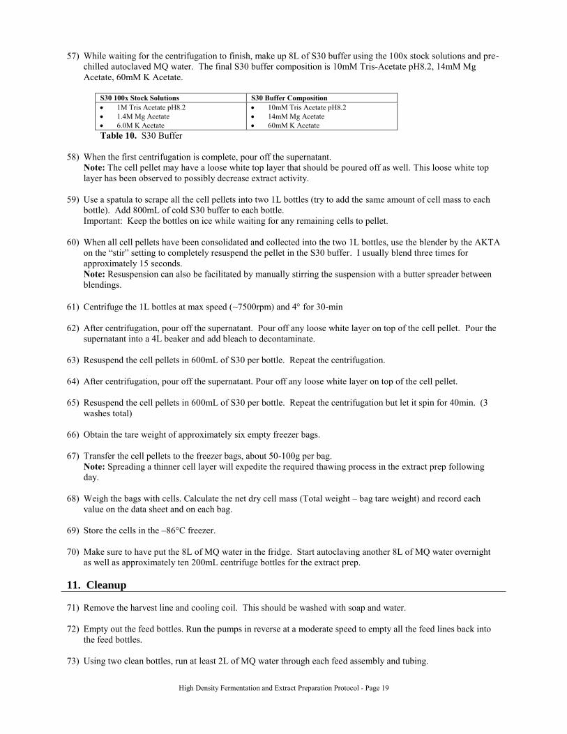
57) While waiting for the centrifugation to finish, make up 8L of S30 buffer using the 100x stock solutions and pre-
chilled autoclaved MQ water. The final S30 buffer composition is 10mM Tris-Acetate pH8.2, 14mM Mg
Acetate, 60mM K Acetate.
S30 100x Stock Solutions S30 Buffer Composition
1M Tris Acetate pH8.2
1.4M Mg Acetate
6.0M K Acetate
10mM Tris Acetate pH8.2
14mM Mg Acetate
60mM K Acetate
Table 10. S30 Buffer
58) When the first centrifugation is complete, pour off the supernatant.
Note: The cell pellet may have a loose white top layer that should be poured off as well. This loose white top
layer has been observed to possibly decrease extract activity.
59) Use a spatula to scrape all the cell pellets into two 1L bottles (try to add the same amount of cell mass to each
bottle). Add 800mL of cold S30 buffer to each bottle.
Important: Keep the bottles on ice while waiting for any remaining cells to pellet.
60) When all cell pellets have been consolidated and collected into the two 1L bottles, use the blender by the AKTA
on the “stir” setting to completely resuspend the pellet in the S30 buffer. I usually blend three times for
approximately 15 seconds.
Note: Resuspension can also be facilitated by manually stirring the suspension with a butter spreader between
blendings.
61) Centrifuge the 1L bottles at max speed (~7500rpm) and 4 for 30-min
62) After centrifugation, pour off the supernatant. Pour off any loose white layer on top of the cell pellet. Pour the
supernatant into a 4L beaker and add bleach to decontaminate.
63) Resuspend the cell pellets in 600mL of S30 per bottle. Repeat the centrifugation.
64) After centrifugation, pour off the supernatant. Pour off any loose white layer on top of the cell pellet.
65) Resuspend the cell pellets in 600mL of S30 per bottle. Repeat the centrifugation but let it spin for 40min. (3
washes total)
66) Obtain the tare weight of approximately six empty freezer bags.
67) Transfer the cell pellets to the freezer bags, about 50-100g per bag.
Note: Spreading a thinner cell layer will expedite the required thawing process in the extract prep following
day.
68) Weigh the bags with cells. Calculate the net dry cell mass (Total weight – bag tare weight) and record each
value on the data sheet and on each bag.
69) Store the cells in the –86°C freezer.
70) Make sure to have put the 8L of MQ water in the fridge. Start autoclaving another 8L of MQ water overnight
as well as approximately ten 200mL centrifuge bottles for the extract prep.
11. Cleanup
71) Remove the harvest line and cooling coil. This should be washed with soap and water.
72) Empty out the feed bottles. Run the pumps in reverse at a moderate speed to empty all the feed lines back into
the feed bottles.
73) Using two clean bottles, run at least 2L of MQ water through each feed assembly and tubing.
High Density Fermentation and Extract Preparation Protocol - Page 20
Note: This should be done the same day as the fermentation. Leaving any residual feed in the lines overnight
will cause their contents to solidify and as a result the tubing will need to be replumbed.
74) From the top port, using the water hose that is connected to the fume hood add ~10L of water to the fermentor.
75) Turn on the agitation rate to 1000rpm and allow it to mix for at least 10 min.
76) Drain the fermentor.
77) Repeat the filling and draining of the fermentor one more time. For the last filling, you can connect the house
cold water tube to the glucose feed exit and fill it up from there to flush out the lines. When you drain, also
drain from the sample port as well as the exit port.
78) Turn off the control panel on the fermentor.
79) Remove the pH and PO2 probes from the fermentor and rinse them with water. Place the green probe-tip
protector cap back on the PO2 probe. Store the probes in the falcon tubes located under the control panel. The
pH electrode should be stored in 3 M KCl. The PO2 probe should be stored in water.
80) Use 70% ethanol and then DI water to rinse out the ports that housed the pH and PO2 probes during
fermentation. Rinse off the caps for each port with 70% ethanol and then DI water and place them back in.
81) Remove the top-feed assembly and all feed lines. All tubing should be washed with soap and water.
82) Remove the base feed line from the base pump.
a) Clamp off the feed tube attached to the inoculation needle both at the inoculation needle and just before the
luer lock.
b) Carefully loosen the cap of the base bottle.
c) Unscrew the luer lock.
d) Cap the luer lock.
e) Tighten the cap of the base bottle.
83) Disconnect the glucose feeding apparatus on the bottom left of the fermentor. All glucose tubing should be
washed with soap and water.
84) Disconnect all wires from the fermentor lid except for the two wires that are attached to the motor (black, ridged
assembly). There is only 1 wire – the wire to the antifoam control (antifoam control is not used). Make sure the
air, steam, and water are turned off. Disconnect all air and water tubing.
85) Use the hex wrench to remove the two screws holding the motor in place. Remove the motor with its two wires
still attached and carefully set it aside on top of the support stand for the fermentor.
86) Disassemble the exhaust filter housing and inspect the filter for damage or excessive accumulation of dirt.
87) Unscrew the pressure sensor from the block at the top of the exhaust cooler and set it aside.
88) Disassemble the condenser.
a) Unclamp the filter housing and remove the cap. Carefully store away the o-ring until reassembly.
b) Remove the filter.
c) Unscrew the base of the condenser connecting it to the fermentor lid.
89) Remove the level sensor (yellow ceramic rod in back) and the plugs, collars, and septa from the lid for washing.
90) Use a small screwdriver and unscrew the small screw holding the air inlet ferm/ster position. Lift the top
portion off to clean. Check the air filter to see if there is cell debris.
91) Set the air inlet to the “ferm” position. Unscrew the four large bolts that hold the lid on and lift the lid off.
Note: The sparge tube/air inlet and the agitator should still be attached.

High Density Fermentation and Extract Preparation Protocol - Page 21
92) Place the lid next to the sink on its side so that it can be washed.
93) Use the crescent wrench to loosen the sparge tube nut and disconnect it. Remove the two screws at the bottom
of it.
94) Wash all parts of the fermentor (except o-rings and filters) as follows:
a) Sparingly wash with Alconox solution (dissolve the soap in a separate container first to avoid leaving
residues).
b) Rinse with water.
c) Rinse with 5% (v/v) acetic acid (optional).
d) Rinse with water.
e) Rinse with 2x with MQ or DI water.
95) Also wash the fermentor itself using soap, water, 5% acetic acid, and DI water. (There is a hose for water from
the hood behind the fermentor).
96) Rinse the o-rings and the septums with DI water.
97) Reassemble the fermentor.
a) Reattach the sparge tube/air inlet onto the fermentor lid.
Note: While attaching the sparge tube back onto the fermentor lid, ensure that the ring of the sparge tube is
concentric with the agitator blades. Also, the hex nut should be pretty tight.
b) Ensure that the o-ring for the fermentor lid is in place and properly situated. The o-ring should go on the
fermentor, and the lid should be placed on it.
c) Place the lid back onto the fermentor. Carefully screw the fermentor lid in place by tightening all bolts
evenly and in pairs that are across from one another.
d) Ensure that the o-ring under the condenser is properly situated.
e) Reassemble the condenser.
98) Rinse the fermentor once with water form the hose connected to the hood’s outlet.
99) Drain the water.
100) Rinse the fermentor with 10L MQ water.
101) Set the stir rate to 1000rpm and allow it to agitate for at least 5-10min.
102) Drain the water.
103) Fill the fermentor with 6-8 L of DI water and sterilize if it will not be used in the next 2-3 days.
a) Turn on the control panel.
b) Make sure the main air, water, and steam supply valves on (on the wall) are still on. .
c) Turn off the water flow to the condenser
d) Raise the air inlet to the “Ster.” Position.
e) Set the air flow to 4 SLPM.
f) Adjust the back-regulator to set the pressure to 0.4 bar.
g) On the control box press the “Sterilization” button and move the cursor to the “Mode” line.
h) Press “Alter” until “Start” is displayed, then press “Enter”.
104) After sterilization, turn off the control unit and close the air, water and steam supply valves.
105) Clean the centrifuge bottles as some will be used the following day.
DAY 3
1. Homogenization Note: For this portion of the protocol keep the extract and critical components on ice whenever possible.

High Density Fermentation and Extract Preparation Protocol - Page 22
1) Use a hammer to break the sheets of cell pellet into smaller pieces. Transfer these pieces to a clean (but not
necessarily autoclaved) 1L centrifuge bottle.
Note: Breaking up the frozen cell pellets into smaller pieces will facilitate the required thawing process.
2) Add 1mL of S30 per 1g of cell mass. Let the cell pellet melt on ice. Occasionally stir with a spatula to speed
up the thawing process.
3) In the meantime, transfer the 8L of autoclaved MQ water to the 4C fridge. Also autoclave 200mL centrifuge
bottles if there are not enough from the previous night.
4) Use the Fischer 700 homogenizer to break up ice and completely re-suspend the cell pellet in the S30 buffer.
Make sure the cell suspension stays cold.
Note: Hand shake the cells to facilitate re-suspension. Avoid foaming if possible.
5) Disrupt cells using the Emulsiflex C-50 homogenizer
a) Plug in the homogenizer and open the valve to the main air supply.
b) Place the cooling coil in a bucket of ice.
c) Run approx. 180-mL of DI water through the tubing. Press the red button on the gray box to start the
homogenizer. Press the red button again to stop the homogenizer when it starts drawing air.
d) Turn the valve to the mostly open position (to the left) and wash with another 100mL of DI water. Use a
plunger to push the remaining water out of the line. Turn the valve back to the mostly closed position (to
the right) before adding cells. Important: Do not over-tighten the valve.
e) Place a new syringe on the inlet line.
f) Add the cell solution to the syringe. Use a spatula to minimize the amount of foam added. Keep the
remaining cell solution on ice.
Note: Avoid using a funnel for adding the cell solution as it may cause spilling.
g) Begin homogenizing.
i) Press the red button to start homogenizing.
ii) Make sure the maximum pressure achieved during homogenization stays around 17500-25000psi.
Note: The maximum pressure may vary depending on the viscosity of the cell lysate. The lysate
flowrate should be around 40-60mL per minute or approximately 1 to 2 piston pumps every second.
The pressure valve can be opened or closed to facilitate maintaining the target pressure and flowrate.
Each pump should draw ~4mL.
iii) Avoid homogenizing the foam on top of the cell solution.
iv) Collect the cell lysate in 200mL centrifuge tubes (also on ice).
Note: The cell lysate should be a significantly darker tan color compared to the cell solution.
Troubleshooting: If the homogenizer draws air, the number of piston strokes will increase to about 5
Troubleshooting: If the homogenizer draws air, it will pump rapidly without product
exiting the outlet. Therefore, turn off the homogenizer. Pour more cell solution into the
syringe. Release the pressure by opening the pressure relief valve. Let some of the cell
extract enter the homogenizer. Then turn on the homogenizer and increase the pressure
with the valve. When the lysate appears at the outlet, Turn up the pressure until the
homogenizer resumes the correct number of strokes/sec. Let the homogenizer run for a
couple of strokes without collecting (3-4 strokes).
Troubleshooting: If the homogenization stalls due to a blockage, it will pump rapidly
without product exiting the outlet. However there will be cell solution in the syringe.
Therefore, release the pressure, using the relief valve until lysate appears in the
outlet. Turn up the pressure until the homogenizer resumes the correct number of
strokes/sec. Let the homogenizer run for a couple of strokes without collecting, until
the lysate darkens in color again (3-4 strokes). Then begin collecting the lysate again.
6) Balance the 200mL tubes and pellet the cell debris at 30,000-g (>14000rpm) and 4C for 30min
7) While waiting for the centrifugation, clean the homogenizer according to the posted protocol.
8) Immediately after centrifugation, collect the supernatant using a pipet and transfer it to new 200mL centrifuge
tubes. Centrifuge the supernatant again at 30,000-g (>14000rpm) and 4C for 30-min.

High Density Fermentation and Extract Preparation Protocol - Page 23
9) Immediately after centrifugation, collect the supernatant using a pipet and transfer it into 50mL disposable
conical tubes on ice. Fill each tube with no more than 40mL.
10) For each mL of extract, add 0.2mL S30 buffer to the tube.
11) Wrap the conical tubes in foil and incubate at 37C on a rotary shaker (~120-rpm) for 80min.
Note: This step is crucial in helping increase the activity of the extract.
2. Extract Dialysis
12) Using the dialysis tubing that was previously prepared, clip one end using a large dialysis clip.
13) Transfer the cell extract to the large dialysis tubing, approximately 50mL per bag.
14) Clamp dialysis tubes tightly and do not leave excessive air pockets/spaces which lead to excessive dilution.
15) Dispense 2L of S30 buffer into two separate beakers. Place a laminar flow stir bar into each beaker.
16) Separate the dialysis tubes into two sets of approximate equal volume. Dialyze each set of tubes against 2L of
S30 buffer for 30min at 4°C.
Note: Also try to keep the ratio of extract to buffer ratio constant between each dialysis vessel.
17) Place the dialysis setup onto stir plates and turn on the agitation.
Note: The dialysis tubes should floating and the short enough so that the stir bar does not come into contact
with them during the dialysis process. The agitation should maintain good circulation but should not disrupt the
dialysis tubes. Poor setup can cause the dialysis tubing to rupture.
18) After 30min, exchange the S30 buffer with fresh S30 buffer. Repeat this process three more times for a total of
four buffer exchanges.
19) Dispense dialyzed cell extract into 200mL centrifuge tube and centrifuge at 10,000-g (8500rpm) and 4C for
20min; immediately collect the supernatant using a pipet and a large autoclaved centrifuge tube (500mL or 1L).
Do not take up any of the pellet. Sacrifice some of the supernatant if needed.
Note: The pellet material can decrease extract activity.
20) Consolidate and mix the cell extract and then immediately aliquot the cell extract (50L, 1mL, 15mL and 50mL
stocks) and label with strain and lot number.
21) Flash freeze the aliquots in liquid nitrogen.
22) Store in the aliquots of extract in the -86 freezer.
23) Test for the activity of the cell extract in a cell free reaction and measure the protein concentration using the
Lowry assay.
Document History Date Signature
Protocol Developed By Jimmy Zawada N/A N/A
Previous Revision Jessica Wu 09-Mar-2007 N/A
Previous Revision Ed Wong 10-Jul-2008 N/A
Current Revision Cem Albayrak &
William Yang 24-Aug-2009
Revision Approved By Jim Swartz