proto-sphera, without toroidal magnets, produces and ... · franco alladio, paolo micozzi,...
TRANSCRIPT

PROTO-SPHERA, without toroidal magnets, produces and confines plasma tori inside magnetostatic fields | Nature Physics
Page 1 of 31
PROTO-SPHERA, without toroidal magnets, produces and confines plasma tori inside magnetostatic fields
FSN Department, CR-ENEA Frascati
Franco Alladio, Paolo Micozzi, Alessandro Mancusoretired, Vincenzo Zanzaretired, Fabrizio
Andreoli, Gerarda Apruzzese, Luca Boncagni, Paolo Buratti, Fabio Crescenzi, Ocleto
D’Arcangelo, Edmondo Giovannozzi, Luigi Andrea Grosso, Alessandro Lampasi, Violeta Lazic,
Simone Magagnino, Valerio Piergotti, Mario Pillon, Selanna Roccella, Giuliano Rocchi,
Alessandro Sibio, Benedetto Tilia, Angelo Tuccillo, Onofrio Tudisco
FSN Department, CREATE Consortium and retired from CR-ENEA Frascati
Giuseppe Maffia
FSN Department, CREATE Consortium, Physics Department Università Roma-1, la Sapienza
Brunello Tirozzi
PlasmaTech Spin-off of Pisa University and Pisa University
Francesco Giammanco, Paolo Marsili
Pisa University
Danilo Giulietti
Università di Padova e Consorzio RFX and FSN Department, CR-ENEA Frascati
Giuseppe Galatola Teka, Matteo Iafrati
Nature Physics (2018)

PROTO-SPHERA, without toroidal magnets, produces and confines plasma tori inside magnetostatic fields | Nature Physics
Page 2 of 31
Abstract
The PROTO-SPHERA experiment has produced and sustained up to ½ sec
axisymmetric magnetically confined current carrying tori around its plasma
centerpost discharge. The centerpost discharge is driven by a DC voltage
applied between electrodes (DC helicity injection) and the tori are formed in
presence of a pre-existing axisymmetric magnetostatic poloidal field only
and in absence of any toroidal magnet. This result provides the first hints
that future Fusion machines could be built with permanent magnets only.

PROTO-SPHERA, without toroidal magnets, produces and confines plasma tori inside magnetostatic fields | Nature Physics
Page 3 of 31
Main
The use of permanent magnets in toroidal plasma confinement would be a
simplification for future controlled fusion reactors. It would avoid any
dissipation connected with normal conducting field coils and would have
great advantages with respect to superconducting coils, which also remove
the ohmic dissipation but require sophisticated cryogenic systems. Magnetic
confinement systems based on permanent magnets have never been
considered so far, for two reasons: 1) For axisymmetric magnetic
confinement1,2, variable currents are needed for breaking-down the plasma,
sustaining its toroidal current and counteracting abrupt plasma
displacements, that can trigger MHD instabilities3. In non-axisymmetric
Stellarators4 no variable field is needed. However another reason was even
more compelling: 2) a toroidal field magnet (irrespective of its axisymmetry)
cannot be built with permanent magnets: the single-valued magnetic scalar
potential that describes any magnetostatic field outside permanent magnets
would be many-valued in the doubly connected domain inside a toroidal field
magnet, this implies the necessity of a net poloidal current through the torus
hole. This picture could be changed by the results recently obtained in the
PROTO-SPHERA experiment5, where a confined plasma torus, carrying a net
toroidal current, has been formed and maintained in absence of any kind of
toroidal magnet and in a pre-existing axisymmetric static magnetic field,
which fills a simply connected region; in this region such a field is equivalent
to a single-valued magnetostatic scalar potential, which could have been
produced by permanent magnets. The results found in PROTO-SPHERA have
been obtained by normal conducting poloidal field (PF) coils only, so this

PROTO-SPHERA, without toroidal magnets, produces and confines plasma tori inside magnetostatic fields | Nature Physics
Page 4 of 31
paper does not yet deal with the design of a configuration based on
axisymmetric permanent magnets.
One of the appealing features of future simply connected axisymmetric
magnetic confinement fusion reactors (mirror symmetric with respect to
their equator as well) is that they will be endowed, on their symmetry axis
and at their edges, with two degenerate X-points6 (null or neutral magnetic
field points). Such fusion reactors could become Fusion Space Thrusters,
expelling charged fusion products preferentially from one of the degenerate
X-points, acting as a “plasma-nozzle” 7. In the deep space environment the
use of permanent magnets for fusion reactors is the most reasonable
possibility, as superconducting magnets would imply the maintenance and
the servicing of a cryogenic system, an endeavor that would be very
impractical to implement in deep space, if not outright impossible.
The PROTO-SPHERA experiment was recently built in its Phase-1 version8,9 in
the ENEA-Frascati Research Center (Fig.1a). Its purpose is to form a
Spherical-Torus (ST, with closed flux surfaces) not around a metal centerpost,
as in Tokamaks, but around a Plasma-Centerpost (PC, with open field and fed
by electrodes), which is an arc discharge with the magnetic structure of a
linear screw pinch, i.e. has both an azimuthal (toroidal) and a longitudinal
(poloidal) field component. The original idea was that of getting rid of all the
central metal components (toroidal field coils and ohmic transformer), which
are the most critical in a Spherical-Tokamak. Thin copper bars outside the
vacuum vessel return the Plasma-Centerpost current from a lower collecting
ring to an upper ring: they are the only components reminiscent of the outer
part of a toroidal magnet in a Tokamak (Fig.1b). Therefore PROTO-SPHERA is
a simply connected magnetic configuration: in Phase-2 it will be composed

PROTO-SPHERA, without toroidal magnets, produces and confines plasma tori inside magnetostatic fields | Nature Physics
Page 5 of 31
Fig.1: The general layout of the experiment.
a, The PROTO-SPHERA load assembly (year 2015). b, The copper bars (shown in red) outside the vacuum vessel10, return the Plasma-Centerpost current from a lower collecting ring to an upper outer coaxial ring; the coaxial cable that feeds the Phase-1 Group-B-PFInt coils is shown in blue. c, Scheme of Spherical-Torus (dark red) around the Plasma-Centerpost (bright red), which terminates on annular electrodes. d, PROTO-SPHERA Argon Plasma Centerpost discharge: pictures from 4 cameras (at different azimuthal angles) are superposed. e, Inside view of the Phase-1 load assembly. f, Inside view of the Phase-2 load assembly.
a b c
d e f
PROTO-SPHERA, without toroidal magnets, produces and confines plasma tori inside magnetostatic fields | Nature Physics
Page 6 of 31
by a Spherical-Torus (with equatorial diameter 2Rsph=0.7 m and a toroidal
plasma current10 IST=¼ MA) and by a Plasma-Centerpost (with total length
LPinch≈2 m and midplane diameter ≈0.08 m), fed by annular electrodes (with
radius =0.40 m and height =0.04 m), and carrying a longitudinal current
Ie=60 kA (electrode plasma current). The Plasma-Centerpost takes the shape
of a mushroom in front of both annular electrodes (Fig.1c). However the
present Phase-1 of the experiment is a partial set-up of the final machine,
built for obtaining the Plasma-Centerpost discharge only (Fig.1d). The
vacuum vessel11 contains only the 8 internal poloidal field of the Group-B-
PFInt shaping coils (Fig.1e): they are all connected in series and fed by a
unique power supply. To complete the machine a further group (Group-A-
PFint, also connected in series) of 10 poloidal field compressing coils will be
built (Fig.1f), the 4 largest among them will provide the vertical field required
to contain the IST =¼ MA Spherical-Torus of Phase-2.
The Phase-1 cathode (Fig.2a) is directly heated (Fig.2b), but is only partially
filled (Fig.2b) with doubly wound Tungsten-VM (WVM) filament modules5,12
(Fig.2c): 54 in Phase-1 vs. the 324 that will fill the cathode in Phase-2. The
anode5,12 is a gas-puffed hollow annular anode (Fig.2d) whose plasma facing
material is Copper-Tungsten (W-Cu, with 90% W); from its rear the gas
discharge is puffed into many hundreds holes facing the plasma, which is
then able to enter inside these holes (Fig.2e). On top of the anode plasma it
has been already possible to observe the “plasma-nozzle”7 from the
degenerate X-point (Fig.2f).
To obtain the Plasma-Centerpost one has to heat the Tungsten filaments
(starting ~30 sec before the plasma); when they have reached ~2900 ºC the
Group-B-PFInt coils are energized, the shaping field (Fig.3a) is produced

PROTO-SPHERA, without toroidal magnets, produces and confines plasma tori inside magnetostatic fields | Nature Physics
Page 7 of 31
inside the 4 cm thick Aluminum vessel; within a few tens of ms the
Centerpost power supply is fired and the screw pinch plasma is produced.
Fig.2: The cathode and the anode of PROTO-SPHERA.
a, The annular cathode resting on the bottom lid. b, Image from the cathode camera during
the Argon shot #842: plasma tubes originate from individual Tungsten filaments at ~2900 ºC.
c, Single module of three Tungsten filaments inserted into the Copper body of the cathode.
d, The annular cathode hanging from the top lid. e, Image from the anode camera during
Argon shot #954. f, View of the “plasma nozzle”7 from the upper degenerate X-point on top
of the anodic plasma, taken while the Plasma-Centerpost is being switched off.
Two gases were used: Argon and Hydrogen. The 10 kA Plasma-Centerpost in
Ar (Fig.3b) was obtained in January 2018, with break-down voltage ~90 V; the
electrode plasma current Ie was sustained at 10 kA while the anode-to-
cathode voltage increased to ~200 V. The equatorial diameter of the Ar
Plasma-Centerpost was 2Rsph~50 cm.
a b c
dd
e f
PROTO-SPHERA, without toroidal magnets, produces and confines plasma tori inside magnetostatic fields | Nature Physics
Page 8 of 31
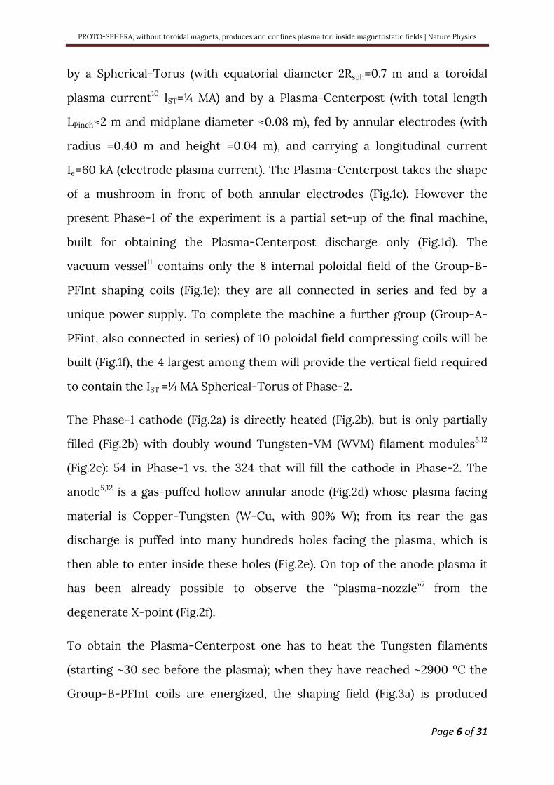
Fig.3: The Plasma-Centerpost produced in Phase-1.
a, Shaping magnetic field produced by the eight Group-B-PFInt coils, the four upper coils are denominated in this figures, the lower four ones being mirror symmetric across the equatorial plane. b, Argon centerpost discharge #954 at Ie=8.5 kA: pictures from 3 cameras (at different azimuthal angles) are superposed. c, Hydrogen discharge #969 at Ie=8.5 kA. d, Inside view of the Phase-1 experiment: the Plasma-Centerpost is drawn in pink color; the Aluminum START11 cylindrical vessel, the lower AISI304 ferrule and the electrodes are removed: two polycarbonate insulators separate the Aluminum vessel from the two ferrules on top and bottom. b, The electrostatic potential13 in H discharges at Ie=10 kA (shown with different colors) is not up/down antisymmetric, i.e. the plasma charges the Group-B-PFInt coils on the anode side with a different pattern of electric potential with respect to the cathode side.
a b c
d e

PROTO-SPHERA, without toroidal magnets, produces and confines plasma tori inside magnetostatic fields | Nature Physics
Page 9 of 31
The equatorial line-averaged electron density <ne> in Argon, surprisingly too
high for a 4 mm interferometer14, was measured by a common-path Second-
Harmonic-Interferometer (SHI)15,16 and exhibited a linear dependence upon
the electrode plasma current: <ne>∝Ie, with <ne>=4•1020 m-3 at Ie=10 kA. As the
magnetic field lines start from and end upon electrodes the Plasma-
Centerpost temperature cannot be larger than a few eV: it has been
determined only at the edge of the anodic mushroom-shaped plasma by
Langmuir probe measurements: the local electron temperature was
measured to vary from 2 to 8 eV, while the local electron plasma density
varied from ne=5•1019 m-3 to ne=2•1019 m-3. Hydrogen too has no interest for
Controlled Fusion17, but it is indicative of the behavior of the Deuterium that
will be used in Phase-2 of the experiment. The 10 kA Plasma-Centerpost in H
(Fig.3c) was also obtained in January 2018, its break-down voltage was ~320 V
and electrode plasma current Ie was sustained at 10 kA while the anode-to-
cathode voltage decreased to ~220 V. The equatorial diameter of the H
Plasma-Centerpost was 2Rsph~60 cm. The equatorial line-averaged electron
density <ne> of the Hydrogen Plasma-Centerpost was <ne>=1.5•1020 m-3 at
Ie=10 kA. Preliminary results of spectroscopic observations18 on the plasma
equator indicate that in Hydrogen discharges the visible spectrum shows
only the Hydrogen lines, whereas the UV spectrum shows limited amounts of
metallic impurities. Both Ar and H Plasma-Centerpost discharges were
sustained until the anode-to-cathode voltage was applied (1 sec). The much
feared anode arc-anchoring of the plasma19,20 (i.e. the discharge
concentrating upon a restricted anode spot, and inflicting local damage)
never occurred; the explanation resides in the rotation of the Plasma-
Centerpost in the azimuthal (toroidal direction), which is evident from the
visible light movies collected by a fast camera. The Plasma-Centerpost

PROTO-SPHERA, without toroidal magnets, produces and confines plasma tori inside magnetostatic fields | Nature Physics
Page 10 of 31
rotates approximately at an angular frequency ω=2π(5•102) radians/sec. The
cause of such a rotation appears to be the electrostatic charging of the PF
coils casings by the plasma itself: all the 8 Group-B-PFInt coils inside the
vacuum vessel reach different floating electric potentials (Fig.3d, indicates
the names of the Group-B-PFInt coils); also the top part of the vessel (an
AISI304 ferrule-and-lid) and its bottom symmetrical ferrule-and-lid are
insulated from the grounded Aluminum middle vessel and left floating. In
Hydrogen plasma at 10 kA, the anode (top) is charged to +140 V while the
cathode (bottom) at -80 V, the top ferrule-and-lid at +95 V while the bottom
ferrule-and-lid at -55 V, the two PF4 coils (plasma-nozzle-coils7) to +50 V on
top and to -10 V on bottom and the PF2\3 coils (mirror-coils) to +95 V on top
and -40 V on bottom. Therefore the E∧B drift of the plasma, that would be
opposite in the anode and cathode region, is not compensated: the top anode
has the larger electrostatic field and determines the direction of the net
plasma rotation. As the internal magnetic field points upwards, while the
electrostatic field goes downwards, from anode to cathode, the net plasma
rotation is clockwise ( seen from the top of the machine).
The scenario imagined for the production of the Spherical-Torus in Phase-2
of PROTO-SPHERA was to start just like in Phase-1, reaching Ie=8.5 kA for the
Plasma-Centerpost current and thereafter to increase rapidly (in ~1 ms) Ie to
60 kA together with the current in the Group-A-PFInt compression coils.
Such a current increase would have contained the torus and would have
provided at the same time, by induction, a part of its toroidal current: Fig.4a
shows the calculated result. Instead in PROTO-SPHERA Phase-1, four
external impromptu PFExt coils (Fig.4b) were added and the current in the
two PFExt coils nearest to the equatorial plane (Fig.4c) was flown in the

PROTO-SPHERA, without toroidal magnets, produces and confines plasma tori inside magnetostatic fields | Nature Physics
Page 11 of 31
toroidal direction opposite to the one of the toroidal component of plasma
current flowing inside the Plasma-Centerpost.
Fig.4: Plasma tori, foreseen for Phase-2 and obtained in Phase-1.
a, Spherical-Torus calculated for the Phase-2 of the experiment, when nearby Group-A-PFInt compression coils (drawn in red) will be added inside the vessel. b, The four additional PFExt coils added outside the vessel (light blue color), viewed from the top and from the bottom lid. c, Calculated equilibrium of a plasma centerpost carrying Ie=10 kA, surrounded by a torus carrying a toroidal current IST =7 kA, using the four PFExt coils. d, Calculated equilibrium of the Plasma-Centerpost in absence of any torus, but with the PFExt compression coils added outside the vessel. e, Centerpost discharge #1098 in Argon at Ie=3 kA: no torus formation. f, Ar-torus discharge #1160 at Ie=10 kA, superposed with the calculated equilibrium at IST=5 kA. g, Ar-torus discharges #1149 and #1160 at Ie=10 kA; in the two discharges the fast camera looks at the two opposing sides to show the overall magnetic separatrix.
a b c
d
e f g
PROTO-SPHERA, without toroidal magnets, produces and confines plasma tori inside magnetostatic fields | Nature Physics
Page 12 of 31
So that the vertical field could hold in equilibrium a plasma torus, should it
form up. The torus formation, because of the outward force due to its
toroidal plasma current, would have enlarged the Plasma-Centerpost
equatorial outboard, approximately into a portion of sphere. The volume of
closed flux surfaces carved out by the torus from the Plasma-Centerpost
would have been quite small (<8%): the field of the external PFExt coils in
Phase-1 is almost vertical (Fig.4c), whereas the future Group-A-PFInt coils of
Phase-2 has been designed in order to carve from the Plasma-Centerpost the
largest possible volume of closed flux surfaces (>95%, Fig.4a). The two
remaining external PFExt coils (farthest from the equatorial plane) are fed
with the opposite direction of current (see Fig.4c), this choice helps in
restoring the correct position of the two plasma mushrooms in front of both
electrodes, to avoid that they are only partially wetted by the plasma
impinging upon them. If the torus was not going to appear, the calculated
equilibrium configuration21 of the Plasma-Centerpost would have had two
ordinary X-point (poloidal field Bpol=0) on the equatorial plane, at ~32 cm
from the symmetry axis (Fig.4d), making the Plasma-Centerpost quite narrow.
When the electrode plasma current is limited to Ie~3 kA, the plasma indeed
conforms to this narrow shape (see Fig.4e). When the current exceeds
Ie~8.5 kA, i.e. the (anode-to-cathode) rotational transform of the Plasma-
Centerpost overcomes /ιe ≥1/2 ( qe ≤ 2 in terms of safety factor), the Ar Plasma-
Centerpost takes instead the shape that the equilibrium calculations21 predict
for the torus formation (Fig.4f) and exhibits an axisymmetric double-null (DN)
divertor (Fig.4g): a fit of the distance between the two X-points of the DN
divertor indicates a toroidal current IST=5 kA inside the Argon-torus (Fig.4c).

PROTO-SPHERA, without toroidal magnets, produces and confines plasma tori inside magnetostatic fields | Nature Physics
Page 13 of 31
The Argon-tori are sustained until the DC anode-to-cathode voltage is
applied; for now this time interval is <0.5 sec, as the external field takes 0.6 s
to penetrate the 4 cm thick Aluminum vacuum vessel and consequently the
plasma break-down has to be delayed. The tori obtained in PROTO-SPHERA
Phase-1, with aspect-ratio A~7.5 and elongation b/a=κ~3.5, have never been
produced in a Tokamak: such a high aspect-ratio and elongation22, in absence
of a close-fitting conducting wall, would not be sustainable23,24. The plasma
break-down voltage increases from 90 V in absence of the torus to 200 V, but
the anode-to-cathode voltage at the current flat-top increases only from
200 V to 220 V: then the power that the Ar-torus sustainment requires is at
most 200 kW, with respect to the 2.0 MW required by the Plasma-Centerpost.
The most surprising asset is the unexpected production of the torus in
absence of any magnetic flux variation, i.e. in a totally magnetostatic
configuration of the axisymmetric poloidal magnetic field pre-existent to the
plasma.
After the formation of the Argon-tori the same endeavor was successfully
made with Hydrogen plasmas. The presence of Hydrogen-tori is most
evident shortly after the plasma break-down (Fig.5a) or during its ramp-down
(Fig.5b). The confined torus appears since the first milliseconds after the
plasma break-down (the current Ie reaches its flat-top value in ~6 msec) and
disappears at a slower rate than the unconfined Plasma-Centerpost, which is
ramped-down in ~3 msec. Fig.5c evidences that the confined current flowing
inside the torus has a longer persistence than the current flowing between
electrodes: in the last msec the torus becomes kink unstable, as the ratio of
its poloidal field (i.e. its toroidal confined current) with respect to its toroidal
field (i.e. the Plasma-Centerpost current) becomes too large.

PROTO-SPHERA, without toroidal magnets, produces and confines plasma tori inside magnetostatic fields | Nature Physics
Page 14 of 31
Fig.5: Hydrogen-tori from plasma break-down to plasma ramp-down.
a, Frame sequence (left to right) of torus formation in H discharge #1202, starting 5 ms after plasma break-down (the Plasma-Centerpost current reaches Ie=10 kA in 6 ms), the images of the equatorial fast camera (1/3 ms time resolution) are separated by 1 ms, but the images of the two anode and cathode slow cameras do not change, as their time resolution is 11 ms. b, Top: Sequence of visible light images, during termination of H discharge #1224 which ramps down from Ie=10 kA in 3 ms. Bottom: same for H discharge #1219, observed through a H-alpha interferometric filter. c, Final sequence of plasma (last 1 ms), observed through H-alpha interferometric filter, but better shown by cold-warm color involution, discharge #1219; frames separated by 1/3 ms. d, Divertor fan interacting with the lower polycarbonate diaphragm in H discharge #1202. e, Divertor fan interacting with the lower AISI304 divertor plate in H discharge #1280. f, Hydrogen-torus discharge #1280 at Ie=10 kA at a later time, superposed with the calculated equilibrium at IST=7 kA.
The tori are limited by a magnetic separatrix endowed with 2 conical divertor
fans. Already in Argon the lower (cathodic) divertor fan is dominant (see
Fig.4g), the Hydrogen divertor has an even more dominant cathodic fan:
almost a single-null (SN) divertor (Fig.5d); the lower divertor fan interacts
with the lower polycarbonate diaphragm, which was not deemed to serve as
a divertor target. An AISI304 lower divertor plate has been recently inserted
a b
c d e f

PROTO-SPHERA, without toroidal magnets, produces and confines plasma tori inside magnetostatic fields | Nature Physics
Page 15 of 31
inside the machine, obtaining an improvement in the up/down symmetry of
the divertor (Fig.5e) and allowing for a fit21 of the distance between the two
X-points, which indicates a toroidal current IST=7 kA inside the Hydrogen-
torus (Fig.5f). However the lower (cathodic) divertor fan still causes spurious
plasma current paths: from the lower divertor, to the plate and finally to the
cathode, but through local plasma sparks impinging upon the lower PF2 coil.
These parasitic current paths will be removed closing all open spaces
between the PF2 and the PF3 coils on bottom ad on top of the machine.
The obtained H-tori have an aspect-ratio A~7 and an elongation b/a=κ~3.5.
The vertical field required by Argon-Tori, in terms of the current flowing in
the PFext coils (fed in series with the Group-B-PFInt coils), was 12.5% smaller
than the maximum current that the PFInt power supply could deliver. Instead
for Hydrogen-tori the vertical field requires a current 25% larger than the
maximum that the PFInt power supply can deliver. The missing PFExt current
was supplemented by adding up a new Supercapacitors25 based power supply,
able to feed a few extra turns of the two PFExt nearest to the equator.
The ratio 1.25/0.875~1.43, between the vertical field required by Hydrogen-
tori and the one required by Argon-tori, confirms that IST~7 kA in H, if
IST~5 kA in Ar. The plasma break-down voltage increases from 320 V (in
absence of torus) to 360 V, but the anode-to-cathode voltage at the current
flat-top increases only from 220 to 240-255 V: then the power that the
H-torus sustainment requires is at most 200-350 kW, with respect to the
2.2 MW required by the H Plasma-Centerpost. However it has to be remarked
that this power exceeds what is required for the sustainment of H-tori, being
presumably also due to the dissipation of spurious current paths in the lower
divertor fan. The robustness of the Plasma-Centerpost+Torus configuration
of PROTO-SPHERA is evident, as a disruption never happens: the tori are
vertically displaced but survive all the changes of the overall plasma
equilibrium, caused by the spurious current paths in the lower Plasma-

PROTO-SPHERA, without toroidal magnets, produces and confines plasma tori inside magnetostatic fields | Nature Physics
Page 16 of 31
Centerpost. The Hydrogen-tori will anyway be sustained for only ¼ sec (see
Fig.6a), until their interaction with the divertor plate will not be fully cured.
If the vertical field is in slight excess of the optimal value, say +10%, the
Plasma-Centerpost produces odd configurations like Double-Tori and Lop-
sided-Tori, all with visible helical components, however also in this case the
plasma never disrupts. Instead there are cases where, after a reduced current
plasma start-up, with Ie<5 kA for quite long times (up to 0.15 sec), the Plasma-
Centerpost current finally achieves Ie=10 kA and forms a proper Plasma-
Centerpost+Torus configuration; which is thereafter maintained until the
anode-to-cathode DC voltage is applied. Fig.6b illustrates shot #1219, with
total duration of ¼ sec, where the plasma remains in a star-shaped state with
Ie<5 kA for ~70 ms (first 4 time slices), later increases to Ie=8 kA in a Double-
Torus configuration and finally metamorphoses (last 100 ms) into a proper
Plasma-Centerpost+Torus configuration. This initial difficulty to form a torus
suggests that the plasma discharge has a part where the current flows in the
Plasma-Centerpost but the rest of the plasma discharge seems trapped in a
axisymmetric-toroidal-cusp configuration26,27 (Fig.6c), coherent with the
hexapolar character of the poloidal field pre-existent to the plasma (Fig.6d).
Also the poloidal field required for PROTO-SPHERA in Phase-2, for shaping
and compressing the Spherical-Torus at IST=¼ MA, has an hexapolar
character, with the complication that the two electrodes (see Fig.6e) are
magnetically disconnected from each other. This disconnection implies
possible difficulties in setting up a Plasma-Centerpost current in a purely
static poloidal field pre-existent to the plasma. Therefore it seems possible
that PROTO-SPHERA in Phase-2 will really have to form up increasing both
the Plasma-Centerpost current Ie to 60 kA as well as the current in the
Group-A-PFInt compression coils, but on a slow time scale, of a few tens of
msec. Such a slow rise however opens the attractive possibility of a
feedback-controlled Spherical-Torus formation.
PROTO-SPHERA, without toroidal magnets, produces and confines plasma tori inside magnetostatic fields | Nature Physics
Page 17 of 31
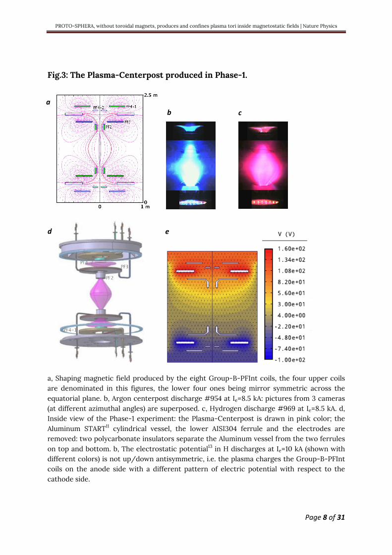
Fig.6: Torus sustained ¼ s & metamorphosis of a toroidal cusp into a torus.
a, Frame sequence (left to right and top to bottom) of equally time-spaced, visible light pictures of H-torus sustainment in discharge #1280, lasting 0.25 sec, with Ie=10 kA and with AISI304 lower divertor plate. b, Same for H-alpha filtered images of the H-torus discharge #1219, with polycarbonate lower divertor plate. In the first 3 frames Ie does not overcome 5 kA and there is no torus, later Ie reaches 10 kA and the configuration metamorphoses into a torus. c, Hexapolar toroidal cusp configuration, in the initial H shot #1221. d, The hexapolar character of the poloidal field pre-existent to the plasma break-down in those two shots. e, The hexapolar character of the poloidal field able to contain the ¼ MA Spherical-Torus of PROTO-SPHERA calculated for Phase-2: the two electrodes (blue) become disconnected from each other, in terms of the pre-existing axisymmetric configuration of static poloidal field.
The evidence that the Hydrogen-tori can appear since the first milliseconds
after the plasma break-down in perfectly static field conditions rules out any
interpretation in terms of inductive phenomena. The only induction being
the one associated with the current increase in the Plasma-Centerpost itself,
just after the break-down: a loop voltage of less than 0.1 V for a few ms would
a b
c d e
PROTO-SPHERA, without toroidal magnets, produces and confines plasma tori inside magnetostatic fields | Nature Physics
Page 18 of 31
drive a current in a direction opposite to the current winding around the
Plasma-Centerpost; such reverse direction current in the torus could not be
held in equilibrium by the external PFExt coils. The field imposed by the
Group-B-PFInt coils is going upwards near the symmetry axis, whereas the
current density is going downwards from anode to cathode, so in the
Plasma-Centerpost the sign of j iB is negative and the plasma current winds
in the Centerpost in the anticlockwise direction (seen from above). Also the
current in the torus is anticlockwise, as the current in the PFExt is in the
clockwise direction and confines the torus. Then the sign of the toroidal
current in the torus is the same as the sign of the toroidal current in the
Plasma-Centerpost: the sign of j iB is negative all over the plasma28,29. This is
a clear sign that it is a DC Helicity Injection in charge of transferring plasma
current from the centerpost to the torus, just as it was imagined when the
PROTO-SPHERA experiment was designed. The presence of ordinary
X-points in the DN divertor is a second hint that magnetic reconnections are
responsible for the sustainment of the torus: in the 2D approximation
magnetic reconnections occur naturally at ordinary X-points30, albeit 3D
effects31 are present, as indicated from the diffused (ergodic) character of the
X-points observed in PROTO-SPHERA. The third hint to magnetic
reconnection is, for Hydrogen-tori, the repetition of distinctive bursts that
shake the plasma shape, with an irregular quasi-periodicity of
2-3 msec; such bursts are accompanied by emissions of plasma into the
separatrix fans. These occurrences are quite reminiscent of the bursting
nature of the “Flux Transfer Events” in the Earth Magnetosphere32 and of
“Solar Flare X-Ray Emission”33, not to mention the repetitive, but not fully
periodic, occurrence of “Sawtooth Oscillations” 34,35 and of “ELM’s activity”36,37
in Tokamaks.

PROTO-SPHERA, without toroidal magnets, produces and confines plasma tori inside magnetostatic fields | Nature Physics
Page 19 of 31
The results illustrated in this paper deal with the first production of plasma
tori in the PROTO-SPHERA experiment, they indicate that:
1) There is no unavoidable need of a toroidal magnet for producing
quasi-axisymmetric magnetically confined tori: a Plasma-Centerpost
discharge, sustained by DC voltage between two electrodes, is
sufficient for obtaining such an aim.
2) The tori can be produced in a pre-existing axisymmetric configuration
of magnetostatic poloidal field: no variations are required in the
poloidal fields that (as per the virial theorem) surround and contain the
plasma.
3) The magnetically confined tori can be maintained in quasi-steady state,
i.e. until the anode-to-cathode DC voltage is applied: magnetic
reconnections are able to provide a completely steady-state current
drive to the toroidal plasma.
4) No disruption phenomena occur in the PROTO-SPHERA magnetic
confinement configuration. The Plasma-Centerpost+Torus
configuration can even produce tori (like the ones here illustrated) that
have an aspect ratio A=7 with an elongation κ=3.5, which in a Tokamak
could absolutely not be produced and sustained.
After many decades, during which magnetic reconnections were the
nightmare of magnetic containment schemes, a useful application of these
natural plasma phenomena could have appeared in magnetic confinement,
hopefully to be consolidated by more significant plasma discharges in future
experimental rounds and, if possible, to be further extended to obtain from
them a vigorous and self-organized plasma heating38,39,40 for the Phase-2 of
PROTO-SPHERA, where a total power of ~15 MW is expected to be input into

PROTO-SPHERA, without toroidal magnets, produces and confines plasma tori inside magnetostatic fields | Nature Physics
Page 20 of 31
the overall plasma. Phase-2 of the experiment will assess the full potential of
this new configuration, when the closed flux surfaces volume that the torus
carves out from the spherically shaped Plasma-Centerpost will increase from
<8% to >95%. If the properties observed in Phase-1 will remain valid and
furthermore if the energy confinement time will be long enough, this
configuration may even be able to solve many issues that have remained
unsolved in the Tokamak case: the removal of the disruption problem and the
necessity of powerful plasma heating and current drive that, instead of
requiring complicated external systems, will become embedded into the
magnetic configuration itself and will rely upon the spontaneous natural
phenomenon of magnetic reconnections.
All these points, when put together, give an even stronger conclusion:
magnetic confinement devices to study Controlled Fusion could in principle
be built using axisymmetric permanent magnets only, able to provide a
poloidal magnetostatic field pre-existent to the plasma. A Plasma-Centerpost
fed by electrodes will produce and sustain the confined torus in such a
poloidal field. In case the two electrodes become disconnected from each
other, in terms of the pre-imposed axisymmetric configuration of permanent
magnets poloidal field, currents of short duration, flowing in a few simply
conducting coils, could be required in addition to the permanent magnets:
however the currents of these coils would be gradually switched off after the
plasma break-down and would vanish when the proper final confinement
configuration, to be sustained by permanent magnets only, is achieved.

PROTO-SPHERA, without toroidal magnets, produces and confines plasma tori inside magnetostatic fields | Nature Physics
Page 21 of 31
Methods
Load assembly and power supplies
The PROTO-SPHERA load assembly was built in the years 2007-2009 by ASG
Superconductors in Genova (Italy) inside the 2 m diameter START vacuum
vessel11, kindly gifted by the Euratom-UKAEA British Association.
The Group-B-PFInt coils are fed by a DC machine that delivers 2 kA at 350 V
DC, built by EEI in Vicenza (Italy), in the years 2011-2014. A further power
supply for the new Group-A-PFInt compression coils will be built in Phase-2,
as a DC machine able to deliver 1.2 kA at 600 V to the 10 new coils connected
in series.
The Plasma Centerpost power supply, built by EEI as well, is instead limited
to the first unit (Ie =10 kA at 350 V DC, for 1.1 sec); a second unit will be built in
Phase-2, able to increase the electrode plasma current up to Ie=60 kA.
The electrical power supply for heating up the cathode is a six-phased AC
machine, also built by EEI, able to deliver 1.7 kA up to 25 V rms to the nine
Tungsten filaments present per phase at this moment; its current capability
will be increased to 10 kA per phase in the Phase-2 version, where 54
Tungsten filaments will be present per phase, in order to increase the
electrode plasma current up to Ie=60 kA.
A new power supply based upon Supercapacitors25 (2 kA at 96 V DC for a few
sec, with a rise time longer than 20 ms), built by OCEM in Bologna, has been
introduced in 2018, able to increase the vertical field produced by the PFExt
coils external to the vessel, in order to meet the requirements imposed by
the formation of the Hydrogen tori.

PROTO-SPHERA, without toroidal magnets, produces and confines plasma tori inside magnetostatic fields | Nature Physics
Page 22 of 31
With the exception of the six-phased AC Cathode heating power supply all
the conductors that carry the currents of the power supply are coaxial cables
(see Fig.1b); in particular the Plasma Centerpost power supply is fed through
two coaxial metal rings on top of the machine, in order to minimize any error
field.
From Fig.3a it is possible to see that an ordinary X-point (poloidal field Bpol=0)
is present on the equatorial plane inside the vacuum vessel at only ~30 cm
from the Aluminum wall. In order to change the magnetic boundary
conditions four external additional PFExt coils were added (Fig.4b). However
the presence of the 4 cm thick Aluminum vacuum vessel and of the two
groups of AISI304 ferrule-and-lid on top and bottom (see Fig.6a) introduces a
skin current that opposes the applied external magnetic and that is totally
dissipated in the Aluminum only after 0.6 sec. Therefore, in order to achieve
steady state conditions with the combined (internal+external) shaping field,
the break-down of the plasma must be delayed by ~0.6 sec: the maximum
duration of the plasma discharge is then reduced from 1.1 sec to just 0.5 sec.
A new insulating vacuum vessel (made out of very thick transparent PMMA,
poly-methyl-methacrylate, being built by Reynolds Polymer Technology in
Grand Junction, CO, USA) will be installed in 2019, then the problem of the
skin current inside the present Aluminum vessel will disappear; four new
PFExt external field coils with less resistance will be set up around the PMMA
vessel, such that the existing Supercapacitor power supply will be able to
feed the whole new PFExt series of coils; it will therefore become possible to
test already in Phase-1 an impulsive torus formation with a 20 ms rise time.

PROTO-SPHERA, without toroidal magnets, produces and confines plasma tori inside magnetostatic fields | Nature Physics
Page 23 of 31
Insulation problems
Argon has no interest whatsoever for Controlled Fusion, it was employed
only as its break-down voltage is very low, from 2015 to end of 2017 Ar was
the gas of choice for learning how to cure a number of insulation problems: a
2 mm thick polycarbonate foil lines the inside of the Aluminum vessel and
two 1 cm thick polycarbonate diaphragms have been glued to this foil near
the two PF2 “mirror coils” (Fig.3a contains all the PF coils names): the
translucent polycarbonate disturbs the images collected by a fast wide-angle
videocamera looking at the Plasma Centerpost, because multiple reflections
can occur.
Both upper and lower parts are separated from the electrically grounded
Aluminum cylinder by two 1 cm thick insulating Polycarbonate rings (see
Fig.3a): the total height of the PROTO-SPHERA vessel is therefore extended
(with respect to START11, which was originally 2 m tall) by the two ferrules
and reaches 2.52 m.
Magnetic measurements
A large number of magnetic probes (about 70) are present near the anode and
near the cathode plasma regions, but there are not magnetic measurements
near the torus (in Phase-1 no magnetic probes were integrated in the main
chamber between the two PF2 “mirror coils”, as the formation of a torus was
not foreseen) however the distance between the two X-points21 of the DN
divertor gives an accurate estimate of the current flowing inside the torus.
The measurements of the original Rogowsky coils that measure the Plasma
Centerpost currents that go through the two PF2 “mirror coils” (see Fig.3a)
have been doubly checked by two supplementary Rogowsky coils that have
been built from the armored cable kindly offered by the firm Axon Cable of

PROTO-SPHERA, without toroidal magnets, produces and confines plasma tori inside magnetostatic fields | Nature Physics
Page 24 of 31
Montmirail (France) and inserted inside the machine just before attempting
the formation of the plasma torus.
Plasma diagnostics
Initial attempts of measuring the Ar Plasma Centerpost equatorial line-
averaged electron density <ne> by a 4 mm interferometer14 were unsuccessful,
because the density was higher than expected but they gave anyhow an
interesting information: although the 4 mm microwave beam was in cutoff no
reflected signal was observed, hinting to the existence of a significant
gradient of electron density from bottom (larger) to top of the Plasma
Centerpost (smaller), able to deflect the microwave beam in the vertical
direction; also the visible images of Ar discharges (Fig. 2a and 3a) show a
relevant vertical inhomogeneity of the light emission.
The line-averaged electron density <ne> of the Ar Centerpost has been
therefore measured on the equatorial plane, by a common-path Second
Harmonic Interferometer (SHI)15,16. The SHI, developed by the “Plasma
Diagnostics & Technologies SRL” (a spin-off of the University of Pisa), is a
device insensitive-to-vibrations, which has allowed an easy installation on
the machine, thanks to a compact modular design. In Hydrogen discharges,
electrode plasma currents much lower than 10 kA exhibited large variation
and were rather difficult to be maintained with steady currents, so the only
reliable line-averaged electron density measurements were performed at
Ie=10 kA, where the equatorial line-averaged electron density was
<ne>=1.5•1020 m-3.
Optical emission (OE) from the Proto-Sphera device is detected by a compact
spectrometer array18 covering the range 235-790 nm, with the resolution
from 0.09 nm in UV to 0.14 nm in IR.

PROTO-SPHERA, without toroidal magnets, produces and confines plasma tori inside magnetostatic fields | Nature Physics
Page 25 of 31
The fast camera that records the largest central portion of the plasma in
visible light, or with an interferometric H-alpha filter in front of the CCD, has
full images of 1024•1024 pixels and sampling rate of ~3kHz.
A radiation survey monitor has been used to verify the presence of hard
x-rays radiation emission during the formation of the plasma arc and torus
configuration. The monitor used was a Victoreen gamma x ray ionization
chamber with an energy measuring range from about 20 keV up to 3 MeV.
The integral of the total dose was measured during some pulses in a position
near a glass window facing the plasma equator but signals above the
background were never detected. This is consistent with the high density of
the plasma produced by PROTO-SPHERA.
References
1 J. Wesson, Tokamaks, 4th ed., Oxford University Press, Oxford (2011)
2 D.H. Crandall, , C.W. Hartman, Y.K.M. Peng, A.L. Hoffman,
R.A. Krakowski, J.D. Sethian, A.E. Robson, Reversed field pinch,
Compact Toroids, and Dense Z-pinch, J Fusion Energy 8, 9–25 (1989)
3 J. Manickam, Allen H. Boozer, and Stefan Gerhardt, Kink modes and
surface currents associated with vertical displacement events, Phys.
Plasmas 19, 082103 ( 2012)
4 Allen H. Boozer, What is a stellarator?, Physics of Plasmas 5, 1647 (1998)

PROTO-SPHERA, without toroidal magnets, produces and confines plasma tori inside magnetostatic fields | Nature Physics
Page 26 of 31
5 F. Alladio, A. Mancuso, P. Micozzi, L. Pieroni, C. Alessandrini, G.
Apruzzese, L. Bettinali, P. Buratti, A. Coletti, P. Costa, C. Crescenzi, A.
Cucchiaro, R. De Angelis, T. Fortunato, D. Frigione, M. Gasparotto, G.
Gatti, R. Giovagnoli, L.A. Grosso, G. Maddaluno, G. Maffia, S. Mantovani,
G. Monari, C. Nardi, S. Papastergiou, M. Pillon, A. Pizzuto, M. Roccella, F.
Rogier, M. Santinelli, L. Semeraro, A. Sibio, B. Tilia, O. Tudisco, L.
Zannelli, V. Zanza, PROTO-SPHERA, ENEA, Serie Energia, Associazione
Euratom-ENEA sulla Fusione, RT/ERG/FUS/2001/14, ISSN: 1124-7932
(2001)
6 M. Tuszewski, Field Reversed Configurations, Nucl. Fusion 28, 2033
(1988)
7 F. Rogier, G. Bracco, A. Mancuso, P. Micozzi, and F. Alladio, Simply
Connected High-Beta Magnetic Configurations, 11TH INTERNATIONAL
CONGRESS ON PLASMA PHYSICS: ICPP 2002, AIP Conference
Proceedings 669, 557 (2003)
8 F. Alladio, P. Costa, A. Mancuso, P. Micozzi, S. Papastergiou and F.
Rogier, Design of the PROTO-SPHERA experiment and of its first step
(MULTI-PINCH), Nucl. Fusion 46, S613–S624 (2006)
9 A. Lampasi, G. Maffia, F. Alladio, L. Boncagni, F. Causa, E. Giovannozzi,
L.A. Grosso, A. Mancuso, P. Micozzi, V. Piergotti, G. Rocchi, A. Sibio, B.
Tilia and V. Zanza, Progress of the Plasma Centerpost for the PROTO-
SPHERA Spherical Tokamak, Energies 9(7), 508 (2016)

PROTO-SPHERA, without toroidal magnets, produces and confines plasma tori inside magnetostatic fields | Nature Physics
Page 27 of 31
10 P. Micozzi, F. Alladio, A. Mancuso and F. Rogier, Ideal MHD stability
limits of the PROTO-SPHERA configuration, Nucl. Fusion 50, 1-10 (2010)
11 A. Sykes, E. Del Bosco, R.J. Colchin, G. Cunningham, R. Duck, T.
Edlington, D.H.J. Goodall, M.P. Gryaznevich, J. Holt, J. Hugill, J. Li, S.J.
Manhood, B.J. Parham, D.C. Robinson, T.N. Todd and M.F. Turner, First
results from the START experiment, Nucl. Fusion 32, 694 (1992)
12 F. Alladio, L.A. Grosso, A. Mancuso, S. Mantovani, P. Micozzi, G.
Apruzzese, L. Bettinali, P. Buratti, R. De Angelis, G. Gatti, G. Monari, M.
Pillon, A. Sibio, B. Tilia, O. Tudisco, Results of Proto-Pinch Testbench
for the PROTO-SPHERA experiment, Proc. of the 27th EPS Conference
on Contr. Fusion and Plasma Phys. Budapest, 12-16 June 2000, ECA Vol.
24B, 161-164 (2000)
13 Karban, P., Mach, F., Kůs, P., Pánek, D., Doležel, I., Numerical solution
of coupled problems using code Agros2D, Computing 95 Issue 1
Supplement, 381-408 (2013)
14 O. Tudisco, A. Lucca Fabris, C. Falcetta, L. Accatino, R. De Angelis, M.
Manente, F. Ferri, M. Florean, C. Neri, C. Mazzotta, D. Pavarin, F.
Pollastrone, G. Rocchi, A. Selmo, L. Tasinato, F. Trezzolani, and A.A.
Tuccillo, A microwave interferometer for small and tenuous plasma
density measurements, Review of Scientific Instruments 84, 033505
(2013)

PROTO-SPHERA, without toroidal magnets, produces and confines plasma tori inside magnetostatic fields | Nature Physics
Page 28 of 31
15 F. Brandi, F. Giammanco, W.S. Harris, T. Roche, E. Trask, and F.J.
Wessel, Electron density measurements of a field-reversed
configuration plasma using a novel compact ultrastable second-
harmonic interferometer, Review of Scientific Instruments 80, 113501
(2009)
16 T. Del Rosso, F. Giammanco, M.G. Anderson, F. Conti, A. Balvis, I. Isakov,
V. Matvienko, G. Strashnoy, W. Waggoner, L. Bonelli, E. Paganini, and
M.W. Binderbauer, Long-path second-harmonic interferometer with
nanosecond time resolution: reliable diagnostic tool for electron
density measurement in pulsed plasma devices, Optics Letters 37, No. 18
3855 (2011)
17 H.A. Bethe and C.L. Critchfield, The formation of Deuterons by Proton
combination, Phys. Rev. 54, 248 (1938)
18 V. Lazic, A. De Ninno, Calibration approach for extremely variable laser
induced plasmas and a strategy to reduce the matrix effect in general,
Spectrochimica Acta Part B 137, 28–38 (2017)
19 D.L. Murphree, R.P. Carter, Observations on magnetically induced
anodic arc region behavior, Journal of Applied Physics 45, 1915 (1974)
20 H.C. Miller, A review of anode phenomena in vacuum arces,
Contributions to Plasma Physics 23, 223-249 (1989)
PROTO-SPHERA, without toroidal magnets, produces and confines plasma tori inside magnetostatic fields | Nature Physics
Page 29 of 31
21 F.Alladio and P. Micozzi, Reconstruction of Spherical Torus Equilibria in
Absence of Magnetic Measurements in the Central Cavity, Nucl. Fusion
37, 1759 (1997)
22 S.C. Cowley , P.K. Kaw , R.S. Kelly , and R.M. Kulsrud, An analytic
solution of high beta equilibrium in a large aspect ratio tokamak,
Physics of Fluids B 3 , 2066 (1991)
23 R.D. Stambaugh, L.L. Lao, E.A. Lazarus, Relation of vertical stability and
aspect ratio in Tokamaks, Nucl. Fusion 32, 1642-1646 (1992)
24 R. Fitzpatrick, A sharp boundary model for the vertical and kink
stability of large aspect-ratio vertically elongated tokamak plasmas,
Physics of Plasmas 15, 092502 (2008);
25 G. Maffia, A. Lampasi, and P. Zito, A new generation of pulsed power
supplies for experimental physics based on supercapacitors, IEEE 15th
International Conference on Environment and Electrical Engineering
(EEEIC), 1067-1072 (2015)
26 J.B. Taylor, Some Stable Plasma Equilibria in Combined Mirror‐Cusp
Fields, Physics of Fluids 6, 1529 (1963)
27 R. Jones, Plasma confinement in an axisymmetric toroidal multipole
cusp, Il Nuovo Cimento B 78, pp 249–254 (1983)

PROTO-SPHERA, without toroidal magnets, produces and confines plasma tori inside magnetostatic fields | Nature Physics
Page 30 of 31
28 J.B. Taylor, Relaxation of Toroidal Plasma and Generation of Reverse
Magnetic Fields, Phys. Rev. Lett. 33, 1139 (1974)
29 J.B. Taylor and M.F. Turner, Plasma current drive by helicity injection in
relaxed states, Nucl. Fusion 29, 219-229 (1989)
30 R.L. Stenzel and W. Gekelman, Magnetic Field Line Reconnection
Experiments 1. Field Topologies, Journal of Geophysical Research 86,
649-658, (1981)
31 V.E. Parnell, J.M. Smith, T. Neukirch, and E.R. Priest, The structure of
three-dimensional magnetic neutral points, Phys. Plasmas 3, 759-770
(1996)
32 D.J. Southwood, C.J. Farrijgia And M.A. Saunders, What Are Flux
Transfer Events?, Planet. Space Sci. 36, 505-508, (1988)
33 P.E. Fehlau, W.H. Chambers, J.C. Fuller, W.E. Kunz, R.W. Milkey And
N.K. Blocker, Periodic Solar Flare X-ray Emission, Nature 232, 42–
43 (1971)
34 V. Goeler, et al. Studies of internal disruptions and m= 1 oscillations
in tokamak discharges with soft—x-ray techniques, Phys. Rev. Lett. 20,
1201 (1974)
35 B.B. Kadomtsev, Disruptive instability in tokamaks, Soviet Journal of
Plasma Physics 1, 389-391 (1975)

PROTO-SPHERA, without toroidal magnets, produces and confines plasma tori inside magnetostatic fields | Nature Physics
Page 31 of 31
36 F. Wagner, G. Becker, K. Behringer, D. Campbell, A. Eberhagen, W.
Engelhardt, G. Fussmann, 0. Gehre, J. Gernhardt, G.V. Gierke, G. Haas,
M. Huang, F. Karger, M. Keilhacker, Q. Kluber, M. Kornherr, K. Lackner,
G. Lisitano, G.G. Lister, H.M. Mayer, D. Meisel, E.R. Müller, H. Murmann,
H. Niedermeyer, W. Poschenrieder, H. Rapp, H. Bohr, F. Schneider, G.
Siller, E. Speth, A. Staebler, K.H. Steuer, G. Venus, O. Vollmer, and Z. Yu.,
Regime of Improved Confinement and High Beta in Neutral-Beam-
Heated Divertor Discharges of the ASDEX Tokamak, Phys. Rev. Lett. 49,
1408-1412 (1982)
37 A. Kirk, H.R. Wilson, R. Akers, N.J. Conway, G.F. Counsell, S.C. Cowley, J.
Dowling, B. Dudson, A. Field, F. Lott, B. Lloyd, R. Martin, H. Meyer, M.
Price, D. Taylor, M. Walsh and the MAST team, Structure of ELMs in
MAST and the implications for energy deposition, Plasma Phys. Control.
Fusion 47, 315 (2005)
38 R.L. Stenzel, W. Gekelman, and N. Wild, Magnetic Field Line
Reconnection Experiments 4. Resistivity, Heating, and Energy Flow,
Journal of Geophysical Research 87, 111-117 (1982)
39 E.G. Zweibel and M. Yamada, Magnetic Reconnection in Astrophysical
and Laboratory Plasmas, Annu. Rev. Astron. Astrophys. 47, 291–332
(2009)
40 E.G. Zweibel and M. Yamada, Perspectives on magnetic reconnection,
Proc. R. Soc. A 472, 20160479 (2016)