protector protector series t c e t o series p liquid-cooled … · 2020. 7. 10. · protector®...
TRANSCRIPT

1 of 9
®
*Assembled in the USA using domestic and foreign parts
INCLUDES: Two-Line LCD Multilingual Digital Evolution™
Controller (English/Spanish/French/Portuguese)With External Viewing Window for EasyIndication of Generator Status and BreakerPosition
Isochronous Electronic Governor
Sound Attenuated Enclosure
Closed Coolant Recovery System
Smart Battery Charger
UV/Ozone Resistant Hoses
±1% Voltage Regulation Field Convertible Fuel Type With No Mechanical
Adjustment Required.
5 Year Limited Warranty
UL 2200 Listed
Listed and labeled by the Southwest ResearchInstitute allowing installation as close as 18 in(457 mm) to a structure*
Protector® Series
Standby Power Rating Model RG048 (Aluminum - Bisque) - 48 kW 60 HzModel RG060 (Aluminum - Bisque) - 60 kW 60 HzModel RG080 (Aluminum - Bisque) - 80 kW 60Hz
Prot
ecto
r® S
erie
s
Meets EPA Emission RegulationsRG048 is CA / MA Emission Compliant
FEATURES INNOVATIVE DESIGN & PROTOTYPE TESTING are key components of
GENERAC’S success in “IMPROVING POWER BY DESIGN.” But it doesn’tstop there. Total commitment to component testing, reliability testing,environmental testing, destruction and life testing, plus testing toapplicable CSA, NEMA, EGSA, and other standards, allows you to chooseGENERAC POWER SYSTEMS with the confidence that these systems willprovide superior performance.
SOLID-STATE, FREQUENCY COMPENSATED VOLTAGEREGULATION. This state-of-the-art power maximizing regulation system isstandard on all Generac models. It provides optimized FAST RESPONSE tochanging load conditions and MAXIMUM MOTOR STARTING CAPABILITYby electronically torque-matching the surge loads to the engine. Digitalvoltage regulation at ±1%.
TEST CRITERIA:
PROTOTYPE TESTED NEMA MG1-22 EVALUATION SYSTEM TORSIONAL TESTED MOTOR STARTING ABILITY
SINGLE SOURCE SERVICE RESPONSE from Generac’s extensive dealernetwork provides parts and service know-how for the entire unit, from theengine to the smallest electronic component.
MOBILE LINK® CONNECTIVITY: Free with select Protector Seriesstandby generator sets, Mobile Link Wi-Fi allows users to monitor thegenerator set status from anywhere in the world using a smartphone, tablet,or PC. Easily access information such as the current operating status andmaintenance alerts. Users can connect an account to an authorized servicedealer for fast, friendly, and proactive service. With Mobile Link, users aretaken care of before the next power outage.
GENERAC TRANSFER SWITCHES. Long life and reliability aresynonymous with GENERAC POWER SYSTEMS. One reason for thisconfidence is the GENERAC product line is offered with its own transfersystems and controls for total system compatibility.
PROTECTOR® SERIESStandby Generators
Liquid-Cooled Gaseous Engine
*Must be located away from doors, windows, and fresh airintakes and in accordance with local codes. PendingLaboratory Testing for RG060 and RG080.https://assets.swri.org/library/DirectoryOfListedProducts/ConstructionIndustry/973_DoC_204_13204-01-01_Rev9.pdf
2 of 9
®
application & engineering data48 / 60 / 80 kW
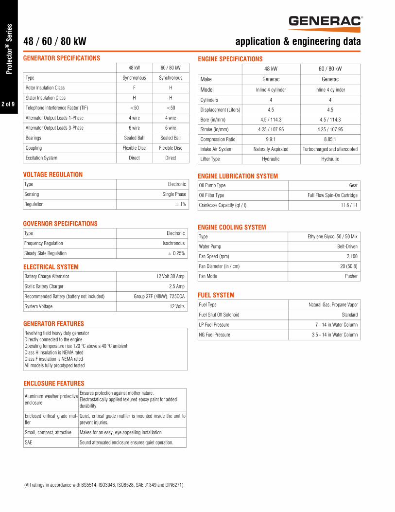
ENGINE SPECIFICATIONS48 kW 60 / 80 kW
Make Generac Generac
Model Inline 4 cylinder Inline 4 cylinder
Cylinders 4 4
Displacement (Liters) 4.5 4.5
Bore (in/mm) 4.5 / 114.3 4.5 / 114.3
Stroke (in/mm) 4.25 / 107.95 4.25 / 107.95
Compression Ratio 9.9:1 8.85:1
Intake Air System Naturally Aspirated Turbocharged and aftercooled
Lifter Type Hydraulic Hydraulic
ENGINE LUBRICATION SYSTEMOil Pump Type Gear
Oil Filter Type Full Flow Spin-On Cartridge
Crankcase Capacity (qt / l) 11.6 / 11
ENGINE COOLING SYSTEMType Ethylene Glycol 50 / 50 Mix
Water Pump Belt-Driven
Fan Speed (rpm) 2,100
Fan Diameter (in / cm) 20 (50.8)
Fan Mode Pusher
FUEL SYSTEMFuel Type Natural Gas, Propane Vapor
Fuel Shut Off Solenoid Standard
LP Fuel Pressure 7 - 14 in Water Column
NG Fuel Pressure 3.5 - 14 in Water Column
ENCLOSURE FEATURES
Aluminum weather protectiveenclosure
Ensures protection against mother nature.Electrostatically applied textured epoxy paint for added durability.
Enclosed critical grade muf-fler
Quiet, critical grade muffler is mounted inside the unit toprevent injuries.
Small, compact, attractive Makes for an easy, eye appealing installation.
SAE Sound attenuated enclosure ensures quiet operation.
GENERATOR FEATURESRevolving field heavy duty generatorDirectly connected to the engineOperating temperature rise 120 °C above a 40 °C ambientClass H insulation is NEMA ratedClass F insulation is NEMA ratedAll models fully prototyped tested
ELECTRICAL SYSTEMBattery Charge Alternator 12 Volt 30 Amp
Static Battery Charger 2.5 Amp
Recommended Battery (battery not included) Group 27F (48kW), 725CCA
System Voltage 12 Volts
GOVERNOR SPECIFICATIONSType Electronic
Frequency Regulation Isochronous
Steady State Regulation ± 0.25%
VOLTAGE REGULATIONType Electronic
Sensing Single Phase
Regulation ± 1%
GENERATOR SPECIFICATIONS48 kW 60 / 80 kW
Type Synchronous Synchronous
Rotor Insulation Class F H
Stator Insulation Class H H
Telephone Interference Factor (TIF) <50 <50
Alternator Output Leads 1-Phase 4 wire 4 wire
Alternator Output Leads 3-Phase 6 wire 6 wire
Bearings Sealed Ball Sealed Ball
Coupling Flexible Disc Flexible Disc
Excitation System Direct Direct
(All ratings in accordance with BS5514, ISO3046, ISO8528, SAE J1349 and DIN6271)
Prot
ecto
r® S
erie
s

3 of 9
®
GENERATOR OUTPUT VOLTAGE/kW - 60 Hz
kW LPG Amp LPG kW Nat. Gas Amp Nat. Gas CB Size (Both)
RG048
120/240 V, 1Ø, 1.0 pf 48 200 48 200 200
120/208 V, 3Ø, 0.8 pf 48 167 48 167 175
120/240 V, 3Ø, 0.8 pf 48 144 48 144 150
277/480 V, 3Ø, 0.8 pf 48 72 48 72 80
RG060
120/240 V, 1Ø, 1.0 pf 60 250 60 250 300
120/208 V, 3Ø, 0.8 pf 60 208 60 208 200
120/240 V, 3Ø, 0.8 pf 60 180 60 180 200
277/480 V, 3Ø, 0.8 pf 60 90 60 90 100
RG080
120/240 V, 1Ø, 1.0 pf Contact Factory Contact Factory 80 333 400
120/208 V, 3Ø, 0.8 pf Contact Factory Contact Factory 80 277 300
120/240 V, 3Ø, 0.8 pf Contact Factory Contact Factory 80 240 300
277/480 V, 3Ø, 0.8 pf Contact Factory Contact Factory 80 120 150
operating data48 / 60 / 80 kW
ENGINE FUEL CONSUMPTION
Natural Gas Propane
(ft³ / hr) (m³ / hr) (gal / hr) (ft³ / hr) (l / hr)
RG048
Exercise cycle 101 2.86 0.67 24.5 2.54
25% of rated load 201 5.7 2.88 104.7 10.9
50% of rated load 336 9.5 4.16 151.3 15.7
75% of rated load 447 12.7 5.28 192 20
100% of rated load 604 17.1 6.61 240.4 25
RG060
Exercise cycle 103 2.9 0.9 33.2 3.5
25% of rated load 257 7.3 2.1 78 8.1
50% of rated load 432 12.2 4.4 161.2 16.8
75% of rated load 618 17.5 6.8 247.2 25.7
100% of rated load 808 22.9 8.4 305.6 31.8
RG080
Exercise cycle 103 2.9 0.9 33.2 3.5
25% of rated load 292 8.3 2.6 93.6 9.7
50% of rated load 534 15.1 5.7 208.8 21.7
75% of rated load 799 22.6 8.3 303.2 31.5
100% of rated load 1,063 30.1 10.8 393.2 40.9
SURGE CAPACITY IN AMPS
Voltage Dip @ < .4 pf
15% 30%
RG048
120 / 240 V, 1Ø 100 300
120 / 208 V, 3Ø 118 242
120 / 240 V, 3Ø 97 189
277 / 480 V, 3Ø 63.6 122.8
RG060
120 / 240 V, 1Ø Contact Factory Contact Factory
120 / 208 V, 3Ø Contact Factory Contact Factory
120 / 240 V, 3Ø Contact Factory Contact Factory
277 / 480 V, 3Ø Contact Factory Contact Factory
RG080
120 / 240 V, 1Ø 283 600
120 / 208 V, 3Ø 236 500
120 / 240 V, 3Ø 204 432
277 / 480 V, 3Ø Contact Factory Contact Factory
Note: Fuel p ipe must be s ized for fu l l load.
For Btu content, multiply ft³ / hr x 2,520 (LP) or ft³ / hr x 1,000 (NG).
For megajoule content, multiply m³ / hr x 93.15 (LP) or m³ / hr x 37.26 (NG).
Refer to “Emissions Data Sheets” for maximum fuel flow for EPA and SCAQMDpermitting purposes.
STANDBY RATING: Standby ratings apply to installations served by a reliable utility source. The standby rating is applicable to varying loads for the duration of a power outage.There is no overload capability for this rating. Ratings are in accordance with ISO-3046-1. Design and specifications are subject to change without notice.
Prot
ecto
r® S
erie
s
4 of 9
®
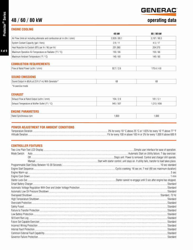
operating data48 / 60 / 80 kW
ENGINE COOLING48 kW 60 / 80 kW
Air Flow (inlet air including alternator and combustion air in cfm / cmm) 2,829 / 80.1 3,197 / 90.5
System Coolant Capacity (gal / liters) 2.9 / 11 4.5 / 17
Heat Rejection to Coolant (BTU per hr / MJ per hr) 201,060 204,570
Maximum Operation Air Temperature on Radiator (°F / °C) 150 / 66 150 / 66
Maximum Ambient Temperature (°F / °C) 140 / 60 140 / 60
COMBUSTION REQUIREMENTSFlow at Rated Power (scfm / cmm) 92.7 / 2.6 170.4 / 4.8
SOUND EMISSIONSSound Output in dB(A) at 23 ft (7 m) With Generator* 68 68
*In exercise mode
EXHAUSTExhaust Flow at Rated Output (scfm / cmm) 104 / 2.9 181 / 5.1
Exhaust Temperature at Muffler Outlet (°F / °C) 945 / 507 1,213 / 656
ENGINE PARAMETERSRated Synchronous rpm 1,800 1,800
POWER ADJUSTMENT FOR AMBIENT CONDITIONSTemperature Deration .................................................................................................................... 3% for every 10 °C above 25 °C or 1.65% for every 10 °F above 77 °FAltitude Deration...........................................................................................................................1% for every 100 m above 183 m or 3% for every 1,000 ft above 600 ft
CONTROLLER FEATURESTwo-Line Plain Text LCD Display.............................................................................................................................................Simple user interface for ease of operation.Mode Switch: Auto ....................................................................................................................................................Automatic Start on Utility failure. 7 day exerciser.
Off .................................................................................................................................Stops unit. Power is removed. Control and charger still operate.Manual .................................................................................................Start with starter control, unit stays on. If utility fails, transfer to load takes place.
Programmable Start Delay Between 10-30 Seconds......................................................................................................................................................... 10 sec standardEngine Start Sequence...............................................................................................................................Cyclic cranking: 16 sec on, 7 rest (90 sec maximum duration)Engine Warm-up.............................................................................................................................................................................................................................. 5 secEngine Cool-Down.......................................................................................................................................................................................................................... 1 minStarter Lock-Out. ........................................................................................................................................Starter cannot re-engage until 5 sec after engine has stopped.Smart Battery Charger.................................................................................................................................................................................................................StandardAutomatic Voltage Regulation With Over and Under Voltage Protection ........................................................................................................................................StandardAutomatic Low Oil Pressure Shutdown ........................................................................................................................................................................................StandardOverspeed Shutdown ....................................................................................................................................................................................................... Standard, 72 HzHigh Temperature Shutdown ...................................................................................................................................................................................................... StandardOvercrank Protection...................................................................................................................................................................................................................StandardSafety Fused...............................................................................................................................................................................................................................StandardFailure to Transfer Protection ......................................................................................................................................................................................................StandardLow Battery Protection ................................................................................................................................................................................................................Standard50 Event Run Log .......................................................................................................................................................................................................................StandardFuture Set Capable Exerciser...................................................................................................................................................................................................... StandardIncorrect Wiring Protection ........................................................................................................................................................................................................ StandardInternal Fault Protection ..............................................................................................................................................................................................................StandardCommon External Fault Capability...............................................................................................................................................................................................StandardGovernor Failure Protection........................................................................................................................................................................................................ Standard
Prot
ecto
r® S
erie
s

5 of 9
®
available accessories48 / 60 / 80 kW
Model # Product Description
G0071690Mobile Link® 4G LTE Cellular Accessory
Generac’s Mobile Link allows you to check the status of your generator from anywhere thatyou have access to an Internet connection from a PC or with any smart device. You will evenbe notified when a change in the generator’s status occurs via e-mail or text message. Note:Harness Adapter Kit required.Available in the U.S. only.
G006478-0Kit, Adapter Mobile Link L/C (Required for QT andRG Series)
The Harness Adapter Kit is required to make liquid-cooled units compatible with MobileLink®.
G007992-0 Cold Weather KitIf the temperature regularly falls below 32 °F (0 °C), install a cold weather kit to maintain optimal battery temperature. Kit consists of battery warmer with thermostat built into thewrap.
G007990-0 Extreme Cold Weather KitRecommended where the temperature regularly falls below 32 °F (0 °C) for extended periodsof time. For liquid cooled units only.
G005651-0 Base Plug Kit Add base plugs to the base of the generator to keep out debris.
G005703-0 - Bisque Paint KitIf the generator enclosure is scratched or damaged, it is important to touch-up the paint toprotect from future corrosion. The paint kit includes the necessary paint to properly maintainor touch-up a generator enclosure.
G007991-0Scheduled Maintenance Kit
The Liquid-Cooled Scheduled Maintenance Kits offer all the hardware necessary to performcomplete maintenance on Generac liquid-cooled generators.
G006664-0 Local Wireless MonitorCompletely wireless and battery powered, Generac's wireless remote monitor provides youwith instant status information without ever leaving the house.
G006665-0Wireless Remote Extension Harness
Recommended for use with the Wireless Remote on units up to 60 kW, required for use onunits 70 kW or greater.
G007993-0 E-StopE-stop allows for immediate fuel shutoff and generator shutdown in the event of an emergen-cy.
G007005-0Wi-Fi LP Fuel LevelMonitor
The Wi-Fi enabled LP fuel level monitor provides constant monitoring of the connected LPfuel tank. Monitoring the LP tank’s fuel level is an important step in making sure your generator is ready to run during an unexpected power failure. Status alerts are availablethrough a free application to notify when your LP tank is in need of a refill.
G007000-0 (50 amp)G007006-0(100 amp)
Smart Management Module
Smart Management Modules (SMM) are used to optimize the performance of a standbygenerator. They manage large electrical loads upon startup and shed them to aid in recovery when overloaded. In many cases, using SMM’s can reduce the overall size andcost of the system.
A0000018981 Ultrasonic Cleaner Solution
An ultra-concentrated anti-corrosive cleaning solution engineered to reach the smallestcavities to clean the toughest contaminants. This water based formula is non-toxic, biodegradable, safe for both metal and plastic surfaces, and is superior in rinsability.
A0000019001 All Surface ProtectantAll surface protectant for vinyl, rubber, plastics creates a barrier that seals & protects sur-faces from water, UV rays while renewing the look of the surface.
Prot
ecto
r® S
erie
s
6 of 9
®
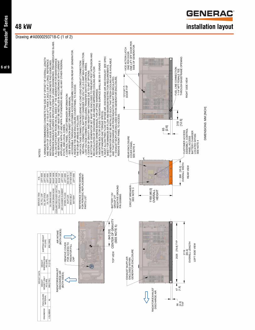
2119
[83.
4]O
VER
ALL
LEN
GTH
1212
[47.
7]D
OO
R T
YP
888
[35.
0]O
VER
ALL
WID
TH
2026
[79.
8] T
YP58 [2
.3]
TYP
47 [1.8
]31
8[1
2.5]
65 [2.6
]
1168
[46.
0]O
VER
ALL
HEI
GH
T
843
[33]
CEN
TER
OF
GR
AVIT
Y(S
EE N
OTE
5)
WEI
GH
T D
ATA
ENG
INE/
KWEN
CLO
SUR
EM
ATER
IAL
WEI
GH
TG
ENSE
T O
NLY
KG [L
BS]
WEI
GH
T SH
IPPI
NG
SKI
DKG
[LBS
]
SHIP
PIN
G W
EIG
HT
KG [L
BS]
4.5L
/48K
WAL
808
[178
1]51
[112
]85
9 [1
893]
SER
VIC
E IT
EM4.
5L
OIL
FIL
L C
AP L
EFT
SID
EO
IL D
IP S
TIC
KLE
FT S
IDE
OIL
FIL
TER
LEFT
SID
EO
IL D
RAI
N H
OSE
RIG
HT
SID
ER
ADIA
TOR
DR
AIN
HO
SER
IGH
T SI
DE
CO
OLA
NT
REC
OVE
RY
BOTT
LER
IGH
T SI
DE
RAD
IATO
R F
ILL
CAP
RO
OF
TOP
AIR
CLE
ANER
ELE
MEN
TLE
FT S
IDE
SPAR
K PL
UG
SLE
FT S
IDE
MU
FFLE
RSE
E N
OTE
11
DR
IVE
BELT
EITH
ER S
IDE
BATT
ERY
LEFT
SID
E
NO
TES:
1. M
INIM
UM
REC
OM
MEN
DED
CO
NC
RET
E PA
D S
IZE
IS 6
" OFF
SET
OF
OVE
RAL
L LE
NG
TH A
ND
WID
TH O
F G
ENER
ATO
R. {
1193
.8 (4
7") W
IDE
X 24
23.2
(95.
4") L
ON
G}.
REF
EREN
CE
IN
STAL
LATI
ON
GU
IDE
SUPP
LIED
WIT
H T
HE
UN
IT F
OR
CO
NC
RET
E PA
D G
UID
ELIN
ES.
REF
EREN
CE
MAN
UFA
CTU
RER
'S S
PEC
IFIC
ATIO
NS
IF U
SIN
G E
NG
INEE
RED
, PR
EFAB
RIC
ATED
SLA
BS.
2. A
LLO
W S
UFF
ICIE
NT
RO
OM
ON
ALL
SID
ES O
F TH
E G
ENER
ATO
R F
OR
MAI
NTE
NAN
CE
AN
D S
ERVI
CIN
G. T
HIS
UN
IT M
UST
BE
INST
ALLE
D IN
AC
CO
RD
ANC
E W
ITH
CU
RR
ENT
APP
LIC
ABLE
NFP
A 37
AN
D N
FPA
70 S
TAN
DAR
DS
AS W
ELL
AS A
NY
OTH
ER F
EDER
AL,
STA
TE, A
ND
LO
CAL
CO
DES
.3.
CO
NTR
OL
PAN
EL /
CIR
CU
IT B
REA
KER
INFO
RM
ATIO
N:
- S
EE S
PEC
IFIC
ATIO
N S
HEE
T O
R O
WN
ERS
MAN
UAL
- A
CC
ESSI
BLE
THR
OU
GH
CU
STO
MER
AC
CES
S AS
SEM
BLY
DO
OR
ON
REA
R O
F G
ENER
ATO
R.
4. R
EMO
VE T
HE
REA
R E
NC
LOSU
RE
CO
VER
PAN
EL T
O A
CC
ESS
TH
E ST
UB-
UP
AREA
S AS
FO
LLO
WS:
- H
IGH
VO
LTAG
E C
ON
NEC
TIO
N IN
CLU
DIN
G A
C L
OAD
LEA
D C
ON
DU
IT C
ON
NEC
TIO
N
NEU
TRAL
CO
NN
ECTI
ON
, BAT
TER
Y C
HAR
GER
120
VO
LT A
C (0
.5 A
MP
MAX
) CO
NN
ECTI
ON
. -
LO
W V
OLT
AGE
CO
NN
ECTI
ON
INC
LUD
ING
TR
ANSF
ER S
WIT
CH
CO
NTR
OL
WIR
ES.
5. C
ENTE
R O
F G
RAV
ITY
AND
WEI
GH
T M
AY C
HAN
GE
DU
E TO
UN
IT O
PTIO
NS.
6. B
OTT
OM
OF
GEN
ERAT
OR
SET
MU
ST B
E EN
CLO
SED
TO
PR
EVEN
T PE
ST IN
TRU
SIO
N A
ND
REC
IRC
ULA
TIO
N O
F D
ISC
HAR
GE
AIR
AN
D/O
R IM
PRO
PER
CO
OLI
NG
AIR
FLO
W.
7. R
EFER
ENC
E O
WN
ERS
MAN
UAL
FO
R L
IFTI
NG
WAR
NIN
GS.
8. M
OU
NTI
NG
BO
LTS
OR
STU
DS
TO M
OU
NTI
NG
SU
RFA
CE
SHAL
L BE
5/8
-11
GR
ADE
5 (
USE
STA
ND
ARD
SAE
TO
RQ
UE
SPEC
S)9.
MU
ST A
LLO
W F
REE
FLO
W O
F IN
TAKE
AIR
, DIS
CH
ARG
E AI
R A
ND
EXH
AUST
. SEE
SPE
C S
HEE
T FO
R M
INIM
UM
AIR
FLO
W A
ND
MAX
IMU
M R
ESTR
ICTI
ON
REQ
UIR
EMEN
TS.
10. G
ENER
ATO
R M
UST
BE
INST
ALLE
D S
UC
H T
HAT
FR
ESH
CO
OLI
NG
AIR
IS A
VAIL
ABLE
AN
D T
HAT
DIS
CH
ARG
E AI
R F
RO
M R
ADIA
TOR
IS N
OT
REC
IRC
ULA
TED
.11
. EXH
AUST
MU
FFLE
R E
NC
LOSE
D W
ITH
IN G
ENER
ATO
R E
NC
LOSU
RE,
REM
OVE
FR
ON
T PA
NEL
TO
AC
CES
S.
TOP
VIEW
LEFT
SID
E VI
EW
REA
R V
IEW
RIG
HT
SID
E VI
EW
RAD
IATO
R/E
XHAU
STD
ISC
HAR
GE
AIR
(BO
TH S
IDES
)
AIR
INTA
KE(B
OTH
SID
ES)
REF
EREN
CE
OW
NER
S M
ANU
ALFO
R P
ERIO
DIC
REP
LAC
EMEN
TPA
RTS
LIS
T
DIM
ENSI
ON
S: M
M [I
NC
H]
EXH
AUST
MU
FFLE
REN
CLO
SED
WIT
HIN
GEN
ERAT
OR
EN
CLO
SUR
E
RAD
IATO
R/E
XHAU
STD
ISC
HAR
GE
AIR
CU
STO
MER
AC
CES
SAS
SEM
BLY,
CO
NTR
OL
PAN
EL A
CC
ESS
BATT
ERY
CH
ARG
ERLO
CAT
ED W
ITH
INSE
E N
OTE
4
REA
R E
NC
LOSU
RE
CO
VER
PAN
ELSE
E N
OTE
4C
IRC
UIT
BR
EAKE
RSE
E N
OTE
3
VIC
E AC
TIO
N L
ATC
H O
NE
PER
DO
OR
O
NE
LIFT
OFF
DO
OR
PER
SID
E O
F G
ENER
ATO
R
FUEL
LIN
E C
ON
NEC
TIO
N1-
1/4"
NPT
FEM
ALE
TEE
THR
OU
GH
BAS
EFR
AME
OPE
NIN
G
REM
OVE
CO
VER
FOR
AC
CES
S TO
RAD
IATO
R F
ILL
CAP
BATT
ERY
12V
GR
OU
P 27
FN
EGAT
IVE
GR
OU
ND
P/N
G05
8665
installation layout48 kWDrawing #A0000293718-C (1 of 2)
Prot
ecto
r® S
erie
s
7 of 9
®
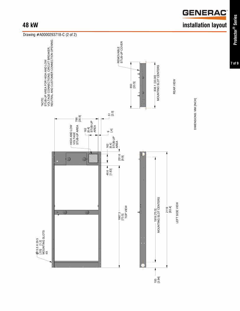
Drawing #A0000293718-C (2 of 2)
Prot
ecto
r® S
erie
s
installation layout48 kW
46.6
[1.8
3]
1867
.3[7
3.5]
251.
6[9
.9]
850
[33.
5]
2119
[83.
4]
786
[30.
9] 51 [2.0
]9 [.4
]16
2[6
.4]
STU
B-U
PAR
EA
162
[6.4
]ST
UB-
UP
AREA
100
[3.9
4]19
19[7
5.5]
MO
UN
TIN
G S
LOT
CEN
TER
S83
8.1
[33.
00]
MO
UN
TIN
G S
LOT
CEN
TER
S
*NO
TE:
STU
B-U
P AR
EA F
OR
HIG
H A
ND
LO
WVO
LTAG
E C
ON
NEC
TIO
NS,
CIR
CU
IT B
REA
KER
,N
EUTR
AL A
ND
CU
STO
MER
CO
NN
ECTI
ON
OPE
NIN
G.
DIM
ENSI
ON
S: M
M [I
NC
H]
LEFT
SID
E VI
EW
13.5
X 2
9.5
[.53]
[
1.2]
MO
UN
TIN
G S
LOTS
4X
HIG
H A
ND
LO
WVO
LTAG
EST
UB-
UP
AREA
TOP
VIEW
REM
OVA
BLE
STU
B-U
P C
OVE
R
REA
R V
IEW

8 of 9
®
Prot
ecto
r® S
erie
s
installation layoutDrawing #A0000293264 (1 of 2)
60 / 80 kW
9 of 9
®
Prot
ecto
r® S
erie
s
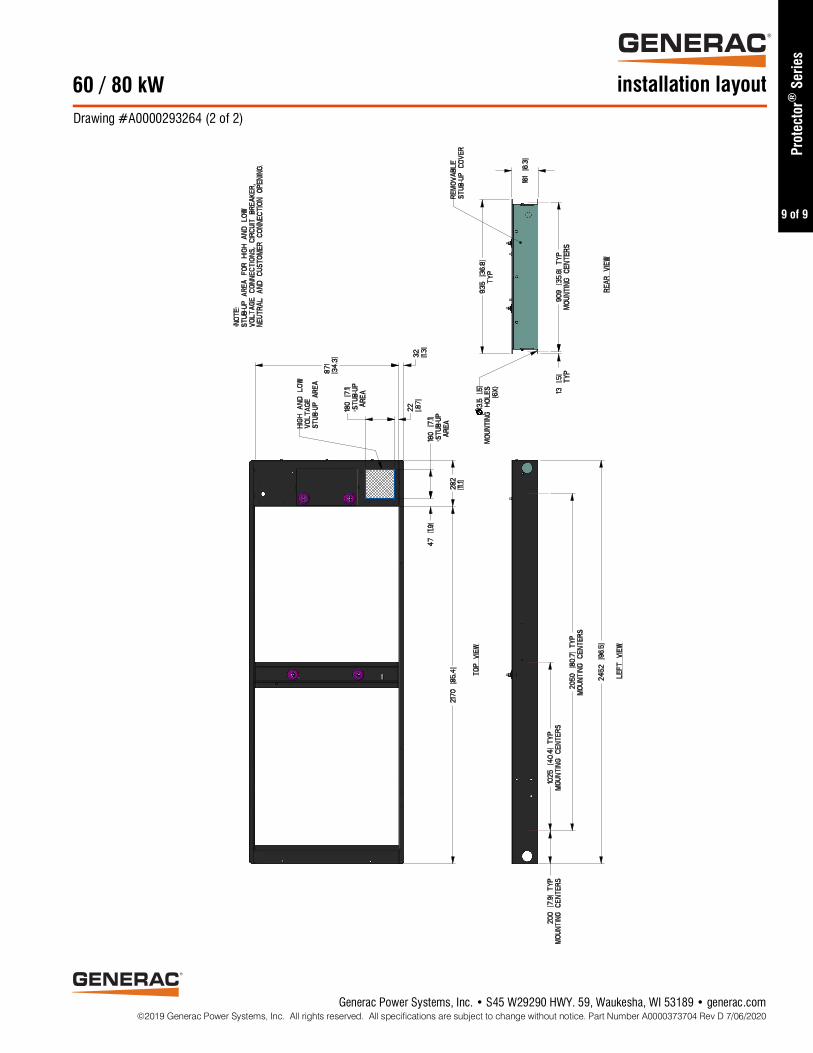
installation layout60 / 80 kWDrawing #A0000293264 (2 of 2)
Generac Power Systems, Inc. • S45 W29290 HWY. 59, Waukesha, WI 53189 • generac.com©2019 Generac Power Systems, Inc. All rights reserved. All specifications are subject to change without notice. Part Number A0000373704 Rev D 7/06/2020
®