protected varan strain gauge module pvai 011 - … · 2016-04-18 · for 1 mv/v res. bridge 8,00...
TRANSCRIPT

PROTECTED VARAN STAIN GAUGE MODULE PVAI 011
15.02.2011 Page 1
Protected VARAN Strain Gauge Module PVAI 011 For a resistance bridge 1.1 mV/V
A bridge circuit with a resolution of 1.1 mV/V can be connected using a 4-wire technology. The supply voltage for the bridge is 10 V. The minimum
bridge resistance is 100 .
Technical Data Interfaces
Interfaces 1 x VARAN-In (M12) (maximum length: 100 m)
Input specifications
Number of channels 1 (4-wire connection)
Measurement range 1.1 mV/V
Measurement value 0 – 4000
Resolution 12-bit
Conversion time per channel 1 ms
Input filter Cutoff frequency 1 kHz (1ms) Low pass 3 system
Supply voltage 10 V/±2.5 %
Maximum voltage supply capacity 100 mA maximum, short circuit proof
Min. Bridge resistance 100
Precision of Analog channel meas-urement
±0.35 % of maximum Measurement value
Repeating accuracy 1.1 mV/V ±0.3 %
Liniearity error 1,1 mV/V ±0.35 %

PROTECTED VARAN STAIN GAUGE MODULEPVAI 011
Page 2 15.02.2011
Electrical requirements
Bus supply voltage 18 – 30 V
Current consumption of the bus supply
Typically 75 mA / + 24 V Maximum 130 mA / 24 V
Miscellaneous
Article number 14-109-011
Hardware version 1.x
Standard UL in preparation
Environmental conditions
Storage temperature -20 – +85 °C
Operating temperature 0 – +60 °C
Humidity 0 – 95 %, uncondensed
EMV stability According to EN 61000-6-2:2001 (industrial area)
Shock resistance EN 60068-2-27 150 m/s²
Protection EN 60529 IP65
Step response of input filter PVAI 011 1mV/V, 2mV/V, 10mV/V oder 20mV/V Sprungantwort
Eingangsfilter CAM 123
0,00 2,00 4,00 6,00 8,00
10,00 12,00
0,00 500,00 1000,00
Time in µs
Vo
lta
ge
in
mV
PVAI 011 input signal delay
0 2 4 6
8 10 12
0 2 4 6
Time in ms
about 300 µs
In/
ou
tpu
t v
olta
ge
For 1 mV/V res. bridge

PROTECTED VARAN STAIN GAUGE MODULE PVAI 011
15.02.2011 Page 3
Mechanical Dimensions

PROTECTED VARAN STAIN GAUGE MODULEPVAI 011
Page 4 15.02.2011
Connector Layout
LED Color Description
V1, VARAN Link Green Lights when the connection between the two PHs is established.
V2, VARAN Active Yellow Lights when data is sent or received over the VARAN bus.
Earthing

PROTECTED VARAN STAIN GAUGE MODULE PVAI 011
15.02.2011 Page 5
X1: VARAN-In (M12 plug, 8-pin)
Pin view X2: Phoenix socket M12, 4-pin
It's absolutely necessary to connect the shielding!
Mating plug to X2: Phoenix type SACC-M12-MSD-4CON-PG-7-SH Phoenix order number: 15 21 25 8
Pin Function
1 n.c. 2 TX+ 3 TX- 4 n.c. 5 RX+ 6 GND 7 +24 V power supply 8 RX-
Pin Function
1 +10V reference voltage 2 AGND 3 Bridge input - 4 Bridge input +
Housing = Earthing (shielding)

PROTECTED VARAN STAIN GAUGE MODULEPVAI 011
Page 6 15.02.2011
Cable layout (VARAN to RJ45)
Pin 7 of the RJ45 can be connected to Pin 6 of the M12; Pin 4 of the RJ45 can be connect-ed to pin 7 of the M12.
IMPORTANT: Pins 1 and 4 of the M12 connector CANNOT be connected!
This cable is customer-specific and does not correspond to VARAN specifications!
More information on the VARAN bus can be found in the VARAN bus specifications!
M12 RJ45
Pin Function Pin Function
1 n.c. 7 GND
2 TX+ <=> 1 TX +
3 TX- <=> 2 TX-
4 n.c. 4 +24 V
5 RX+ <=> 3 RX +
6 GND <=> 8 GND
7 +24 V power supply <=> 5 +24 V
8 RX- <=> 6 RX -

PROTECTED VARAN STAIN GAUGE MODULE PVAI 011
15.02.2011 Page 7
Wiring Guidelines The signals recorded by the analog modules are very small, as compared to the digital signals. To ensure error-free operation, a careful wiring method must be followed:
The earth connection must be connected properly to mass.
The connection lines to the source of the analog signals must be as short as possible and parallel wiring to digital signal lines must be avoided.
The signal lines must be shielded.
The shielding should be connected to a shielding bus. If no shielding bus is available, the shield can also be clamped to the connectors (see below).
1.1 mV/V Bridge Circuit

PROTECTED VARAN STAIN GAUGE MODULEPVAI 011
Page 8 15.02.2011
Addressing
Address RD/WR Function / Bits
$00 RD16 Analog measurement value of the reference voltage
$02 RD16 Analog measurement value, Channel 1 (0 – 10 V)
$04 RD8
Bit 0: ADC error Bit1: Reference OK Bit2: Reference output OK (max. current 100 mA) Bit3.. 7: reserved
Calibration Data (Serial Flash) The data is located, according to the VARAN bus specifications, in the serial Flash memory under the ID number 10 (area: calibration data). The data for this module is organized as follows:
Address BYTE Description
0000 4 Check sum
0004 4 Scan version
0008 4 Scan length
Bit 31..0: scan length
000C 4 Number of channels
0010 4 AI0 Offset = Reference voltage at the time of calibration
0014 4 AIO Multiplier = not used
0018 4 AIO Divisor = not used
001C 4 AI1 Offset
0020 4 AI1 Multiplier
0024 4 AI1 Divisor

PROTECTED VARAN STAIN GAUGE MODULE PVAI 011
15.02.2011 Page 9
VARAN Recommended Shielding The VARAN real-time Ethernet bus system offers robust performance in harsh industrial environments. Through the use of IEEE 802.3 standard Ethernet physics, the potential between an Ethernet line and sending/receiving components is kept separate. The VARAN Manager resends messages to a bus participant immediately when an error occurs. It is principally recommended that the shielding guidelines below be followed. For applications in which the bus line is run outside the control cabinet, correct shielding is required. This is especially important, if due to physical requirements, the bus lines must be placed next to sources of strong electromagnetic noise. It is recommended that whenever possible, to avoid wiring VARAN-Bus lines parallel to power cables. SIGMATEK recommends the use of CAT5e industrial Ethernet bus lines.
For the shielding variants, an S-FTP bus line is recommended, which is a symmetric, multi-wire cable with unshielded pairs. For the total shielding, a combination of foil and braiding is used; it is recommended that an unvarnished variant be used.

PROTECTED VARAN STAIN GAUGE MODULEPVAI 011
Page 10 15.02.2011
1. Wiring from the Control Cabinet to an External VARAN Com-ponent If the Ethernet lines are connected from a VARAN component to a VARAN node outside the control cabinet, the shielding should be placed at the entry point to the control cabinet housing. All noise can then be deflected from the electronic components before reaching the module.
PROTECTED VARAN STAIN GAUGE MODULE PVAI 011
15.02.2011 Page 11
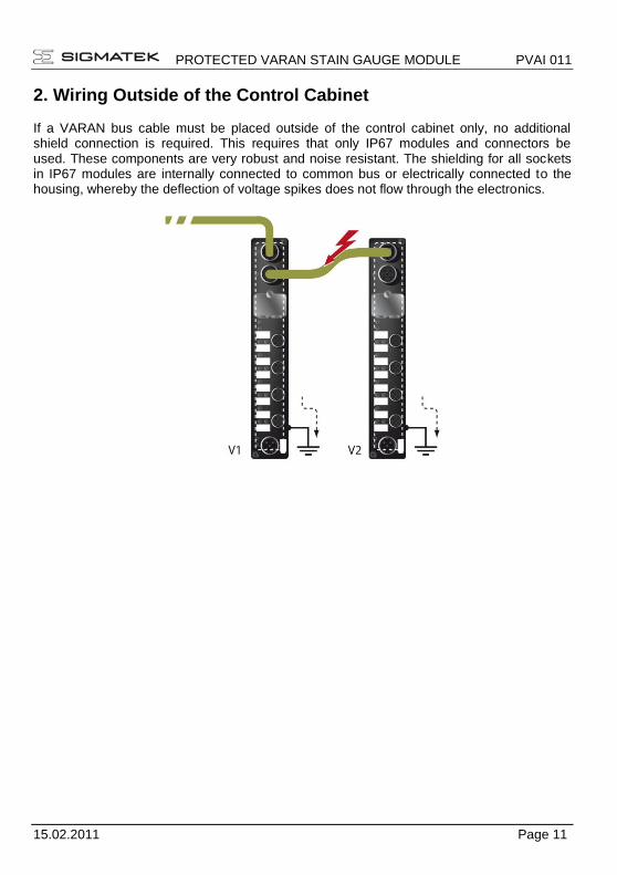
2. Wiring Outside of the Control Cabinet If a VARAN bus cable must be placed outside of the control cabinet only, no additional shield connection is required. This requires that only IP67 modules and connectors be used. These components are very robust and noise resistant. The shielding for all sockets in IP67 modules are internally connected to common bus or electrically connected to the housing, whereby the deflection of voltage spikes does not flow through the electronics.

PROTECTED VARAN STAIN GAUGE MODULEPVAI 011
Page 12 15.02.2011
3. Shielding for Wiring Within the Control Cabinet Sources of strong electromagnetic noise located within the control cabinet (drives, Trans-formers, etc.) can induce interference in a VARAN bus line. Spike voltages are deflected over the metallic housing of a RJ45 connector. Noise is conducted through the control cabi-net housing without further action from the electronic components To eliminate sources of noise during data transfer, it is recommended that the shielding from all electronic compo-nents be connected within the control cabinet.
PROTECTED VARAN STAIN GAUGE MODULE PVAI 011
15.02.2011 Page 13
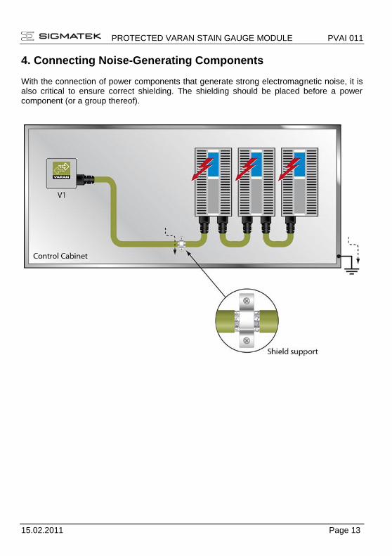
4. Connecting Noise-Generating Components With the connection of power components that generate strong electromagnetic noise, it is also critical to ensure correct shielding. The shielding should be placed before a power component (or a group thereof).
PROTECTED VARAN STAIN GAUGE MODULEPVAI 011
Page 14 15.02.2011
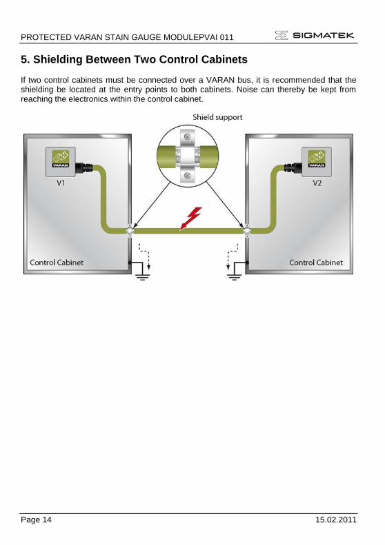
5. Shielding Between Two Control Cabinets If two control cabinets must be connected over a VARAN bus, it is recommended that the shielding be located at the entry points to both cabinets. Noise can thereby be kept from reaching the electronics within the control cabinet.