prosthodontic manual · 2015-01-08 · 10 11 the economical implant system • permanent...
TRANSCRIPT

PROSTHODONTIC MANUAL
www.bego-implantology.com
2 3
1. BEGO Semados® implants 6
1.1 BEGO Semados® S implants – “The All-Rounders” 7
1.2 BEGO Semados® RI implants – “The Specialists” 8
1.3 Implant-prosthesis interface 9
1.4 BEGO Semados® Mini implants – “The Narrow Ridge Experts” 10
1.5 TiPurePlus – The high-purity BEGO implant surface 12
2. Prosthodontic BEGO Semados® S / RI-Line (Sub system) 13
2.1 Examples of restoration with BEGO Semados® S or RI-Line (Sub system) 13
2.1.1 Single tooth replacement 13
2.1.2 Bridges 13
2.1.3 Secondary connection 14
2.1.4 Removable prostheses 14
3. Prosthodontic BEGO Semados® S / RI-Line (Supra system) 15
3.1 Examples of restoration with BEGO Semados® S or RI-Line (Supra system) 15
4. Prosthodontic BEGO Semados® Mini-Line 15
4.1 Examples of restoration with BEGO Semados® Mini-Line 15
5. BEGO Semados® materials 16
5.1 General information 16
5.2 Torques 17
5.3 Titanium 18
5.4 Wirobond® MI 19
5.5 Composition of materials 20
6. General instructions for use of BEGO Semados® implant superstructure 22
6.1 Investing / Casting / Defl asking 22
6.2 Sheffi eld test 25
7. General safety instructions 26
8. Fabrication of a custom impression tray for the BEGO Semados® system 27
9. Fabrication of a drill template for the BEGO Semados® system 28
9.1 Light-curing autopolymer basis 28
9.2 Thermoplastic procedure 30
10. BEGO Semados® S / RI Sub-Dent closed tray impressions 33
10.1 Impression-taking for implants with Sub-Dent closed tray impressions 33
10.2 Model-making with Sub-Dent closed tray impressions 35
11. BEGO Semados® S / RI Sub-Dent open tray impressions 37
11.1 Impression-taking for implants with Sub-Dent open tray impressions 37
11.2 Model-making with Sub-Dent open tray impressions 38
12. BEGO Semados® Mini open tray impressions 40
12.1 Impression-taking for implants with Mini open tray impressions 40
12.2 Model-making with Mini open tray impressions 41The present Prosthetic Manual shall supersede all previous versions.
The manufacturer can accept no liability for any damage or injury resulting from failure to observe these instructions.
TABLE OF CONTENTS
4 5
13. BEGO Semados® S / RI Supra-Dent closed tray impressions 43
13.1 Impression-taking for implants with Supra-Dent closed tray impressions 43
13.2 Model-making with Supra-Dent closed tray impressions 45
14. BEGO Semados® S / RI Supra-Dent open tray impressions 47
14.1 Impression-taking for implants with Supra-Dent open tray impressions 47
14.2 Model-making with Supra-Dent open tray impressions 49
15. BEGO Semados® S / RI / Mini 1DALBO®-Plus ball attachment impression set 51
15.1 Impression-taking with 1DALBO®-Plus ball attachment impression set 51
15.2 Model-making with 1DALBO®-Plus ball attachment impression set 53
16. BEGO Semados® S / RI Sub-Dent magnetic impressions 55
16.1 Impression-taking with Sub-Dent magnetic impressions 55
16.2 Model-making with Sub-Dent magnetic impressions 57
17. BEGO Semados® S / RI 2Locator® impressions 58
17.1 Impression-taking with 2Locator® impression coping 58
17.2 Model-making with 2Locator® impression coping 60
18. Temporary restorations on BEGO Semados® S / RI implants 61
18.1 Sub-Tec provisional abutment ø 5.5 / 7 – long-term temporary restoration 61
18.2 Sub-Tec provisional abutment ø 5.5 / 7 – immediate temporary restoration 63
18.3 Sub-Tec provisional titanium abutment 65
18.4 Sub-Tec provisional titanium abutment no Hex 67
19. Superstructures on BEGO Semados® S / RI implants (Supra system) 69
19.1 Supra-Tec Universal 69
19.2 Supra-Tec gold cast-on 73
20. Superstructures on BEGO Semados® S / RI implants (Sub / Supra system) 78
20.1 Sub / Supra-Tec ball attachment 78
21. Superstructures on BEGO Semados® S / RI implants (Sub system) 80
21.1 Sub-Tec magnetic abutment 80
21.2 Sub-Tec 2Locator® abutment 82
21.3 Sub-Tec 2Locator® abutment – Optional intraoral completion 85
21.4 BeCe Sub-Tec ceramic abutment 87
21.5 Sub-Tec titanium abutment, conical 90
21.6 Sub-TecPlus solid abutments – assortment set 0° / 15° / 20° 94
21.7 Sub-TecPlus solid abutments 95
21.8 Sub-Tec Universal 99
21.9 Sub-Tec Universal no Hex 104
21.10 Recommended adhesives for Sub-Tec universal abutments 109
21.11 Sub-Tec Wirobond® MI laser base no Hex 110
21.12 Sub-Tec gold cast-on abutment 113
21.13 Sub-Tec gold cast-on abutment no Hex 119
21.14 Sub-Tec titanium / Wirobond® MI bar abutment 125
21.15 Sub-Tec CAD Positioner 128
21.16 Sub-Tec CAD / CAM titanium adhesive abutment / scanning abutment 130
1 DALBO® is a registered trademark of Cendres & Métaux SA, Biel / Bienne, Switzerland2Locator® is a registered trademark of Zest Anchors Inc., CA, USA
22. Superstructures on BEGO Semados® Mini implants 134
22.1 Wirobond® MI Mini bar system 134
22.2 Mini gold bar abutment 137
22.3 Mini ball attachment (PRECI-CLIX) 140
22.4 Wirobond® MI Mini abutment conical 142
23. Secondary connection 145
23.1 Secondary connection 1.2 mm (set) 145
6 7
1. BEGO SEMADOS® IMPLANTS
BEGO Semados® implants: the last word in modern
and cost-effective dental implantology!
• Cost-effective
• Simple to use
• Practical
• Quality product manufactured entirely in Germany
• Clinically tested
• Versatile
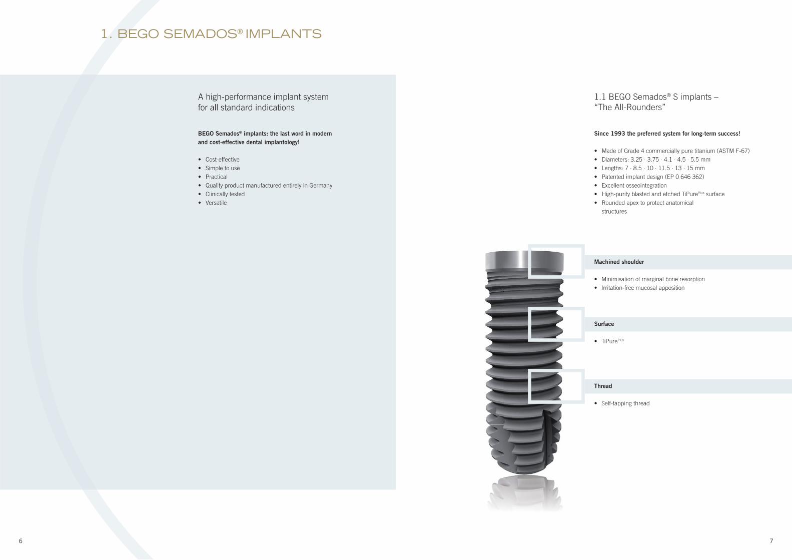
Since 1993 the preferred system for long-term success!
• Made of Grade 4 commercially pure titanium (ASTM F-67)
• Diameters: 3.25 · 3.75 · 4.1 · 4.5 · 5.5 mm
• Lengths: 7 · 8.5 · 10 · 11.5 · 13 · 15 mm
• Patented implant design (EP 0 646 362)
• Excellent osseointegration
• High-purity blasted and etched TiPurePlus surface
• Rounded apex to protect anatomical
structures
Machined shoulder
• Minimisation of marginal bone resorption
• Irritation-free mucosal apposition
Surface
• TiPurePlus
Thread
• Self-tapping thread
1.1 BEGO Semados® S implants –
“The All-Rounders”
A high-performance implant system
for all standard indications
8 9
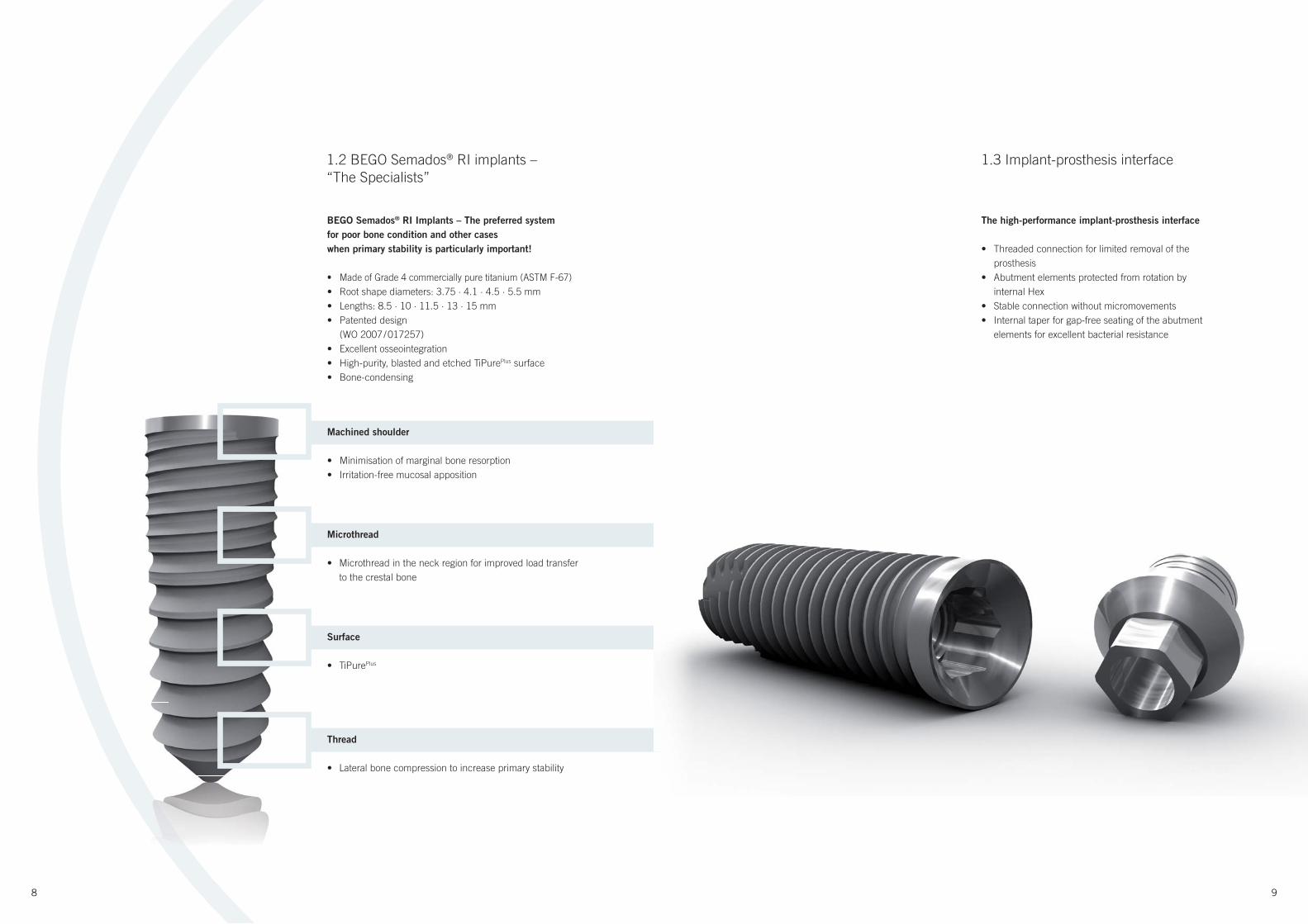
The high-performance implant-prosthesis interface
• Threaded connection for limited removal of the
prosthesis
• Abutment elements protected from rotation by
internal Hex
• Stable connection without micromovements
• Internal taper for gap-free seating of the abutment
elements for excellent bacterial resistance
BEGO Semados® RI Implants – The preferred system
for poor bone condition and other cases
when primary stability is particularly important!
• Made of Grade 4 commercially pure titanium (ASTM F-67)
• Root shape diameters: 3.75 · 4.1 · 4.5 · 5.5 mm
• Lengths: 8.5 · 10 · 11.5 · 13 · 15 mm
• Patented design
(WO 2007 / 017257)
• Excellent osseointegration
• High-purity, blasted and etched TiPurePlus surface
• Bone-condensing
Machined shoulder
• Minimisation of marginal bone resorption
• Irritation-free mucosal apposition
Microthread
• Microthread in the neck region for improved load transfer
to the crestal bone
Surface
• TiPurePlus
Thread
• Lateral bone compression to increase primary stability
1.2 BEGO Semados® RI implants –
“The Specialists”
1.3 Implant-prosthesis interface
10 11
The economical implant system
• Permanent restoration of edentulous, atrophied
alveolar ridges with prefabricated bar system
• Shorter treatment time thanks to
avoidance of time-consuming augmentation
• Low-cost form of treatment
• Strong, prosthetic solutions using Wirobond®
MI abutments
• Single tooth and ball attachment restorations
possible with implant diameters of 2.9 and 3.1 mm
BEGO Semados® Mini implants:
the last word in modern and cost-effective
dental implantology!
• Cost-effective
• Simple to use
• Practical
• Quality product manufactured entirely in Germany
• Clinically tested
• Versatile
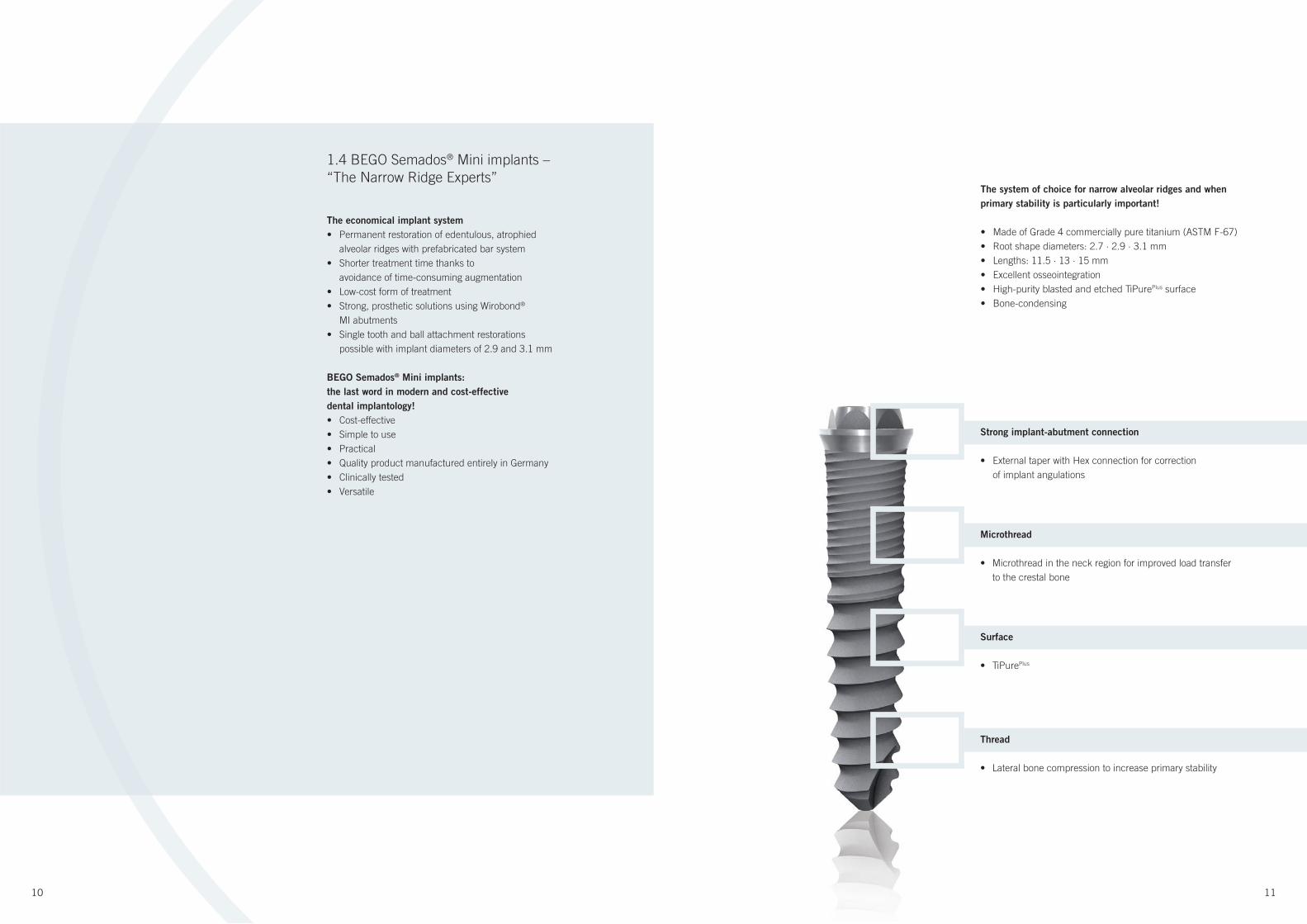
The system of choice for narrow alveolar ridges and when
primary stability is particularly important!
• Made of Grade 4 commercially pure titanium (ASTM F-67)
• Root shape diameters: 2.7 · 2.9 · 3.1 mm
• Lengths: 11.5 · 13 · 15 mm
• Excellent osseointegration
• High-purity blasted and etched TiPurePlus surface
• Bone-condensing
1.4 BEGO Semados® Mini implants –
“The Narrow Ridge Experts”
Strong implant-abutment connection
• External taper with Hex connection for correction
of implant angulations
Microthread
• Microthread in the neck region for improved load transfer
to the crestal bone
Surface
• TiPurePlus
Thread
• Lateral bone compression to increase primary stability
12 13
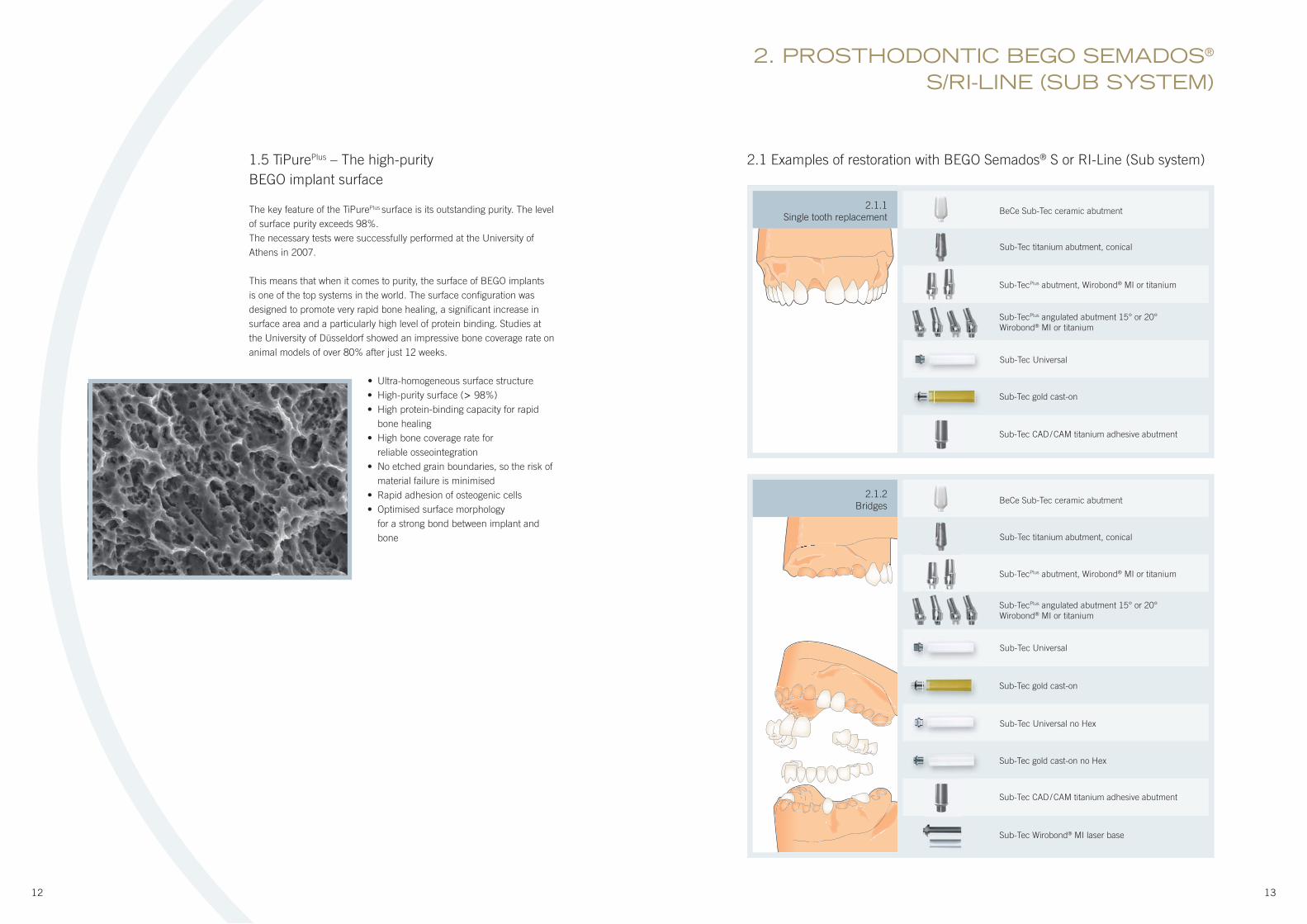
1.5 TiPurePlus – The high-purity
BEGO implant surface
The key feature of the TiPurePlus surface is its outstanding purity. The level
of surface purity exceeds 98%.
The necessary tests were successfully performed at the University of
Athens in 2007.
This means that when it comes to purity, the surface of BEGO implants
is one of the top systems in the world. The surface confi guration was
designed to promote very rapid bone healing, a signifi cant increase in
surface area and a particularly high level of protein binding. Studies at
the University of Düsseldorf showed an impressive bone coverage rate on
animal models of over 80% after just 12 weeks.
• Ultra-homogeneous surface structure
• High-purity surface (> 98%)
• High protein-binding capacity for rapid
bone healing
• High bone coverage rate for
reliable osseointegration
• No etched grain boundaries, so the risk of
material failure is minimised
• Rapid adhesion of osteogenic cells
• Optimised surface morphology
for a strong bond between implant and
bone
2. PROSTHODONTIC BEGO SEMADOS®
S/RI-LINE (SUB SYSTEM)
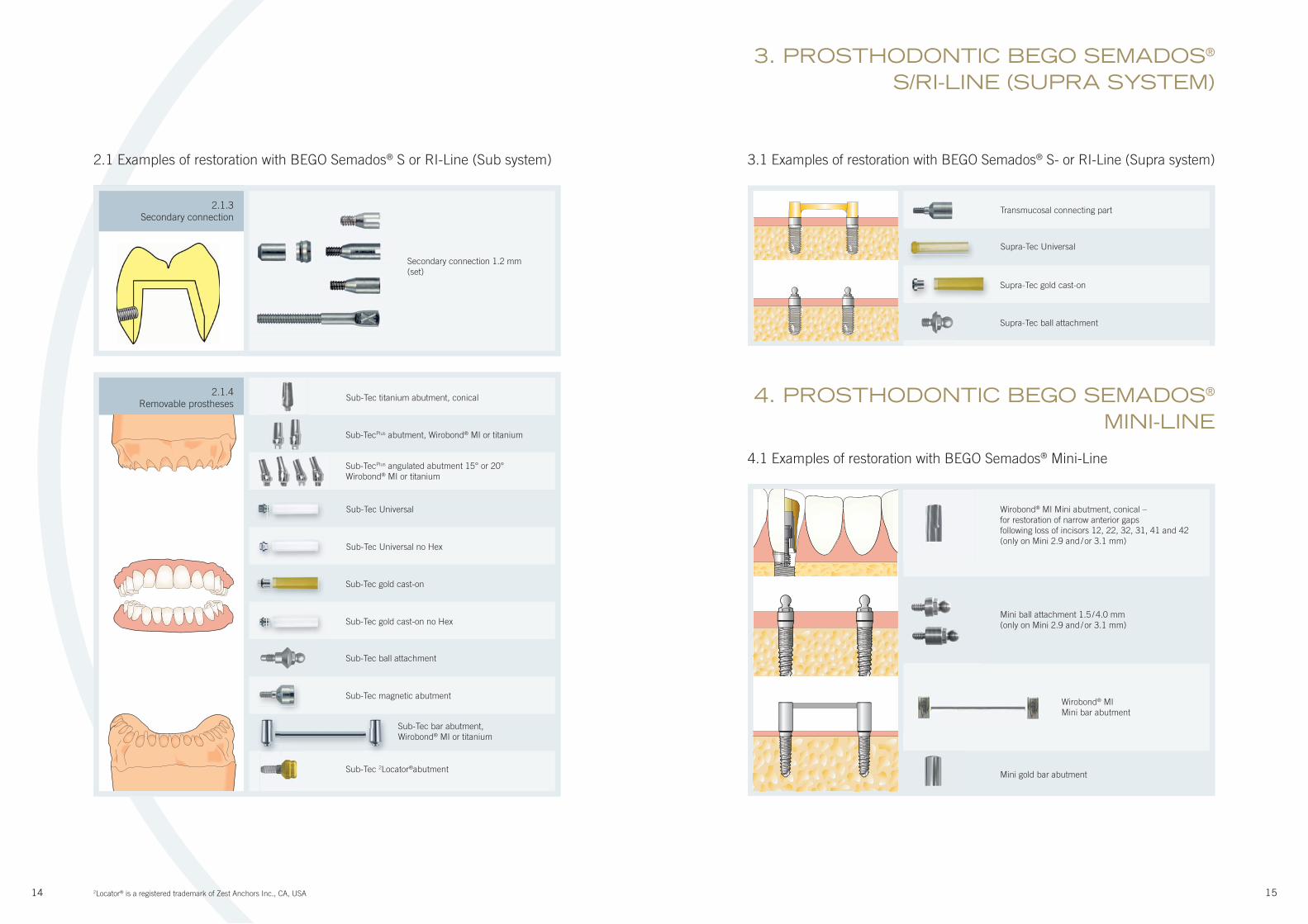
2.1 Examples of restoration with BEGO Semados® S or RI-Line (Sub system)
2.1.1
Single tooth replacement
Sub-Tec titanium abutment, conical
BeCe Sub-Tec ceramic abutment
Sub-TecPlus abutment, Wirobond® MI or titanium
Sub-TecPlus angulated abutment 15° or 20°
Wirobond® MI or titanium
Sub-Tec gold cast-on
Sub-Tec CAD / CAM titanium adhesive abutment
2.1.2
Bridges
Abb kommt neu
Sub-Tec Universal
Sub-Tec Universal
Sub-Tec Universal no Hex
Sub-Tec gold cast-on
Sub-Tec gold cast-on no Hex
BeCe Sub-Tec ceramic abutment
Sub-Tec titanium abutment, conical
Sub-TecPlus abutment, Wirobond® MI or titanium
Sub-TecPlus angulated abutment 15° or 20°
Wirobond® MI or titanium
Sub-Tec Wirobond® MI laser base
Sub-Tec CAD / CAM titanium adhesive abutment
b kommt neub kommt neubbbbbbbAbb kommt neu
14 15
3. PROSTHODONTIC BEGO SEMADOS®
S/RI-LINE (SUPRA SYSTEM)
4. PROSTHODONTIC BEGO SEMADOS® MINI-LINE
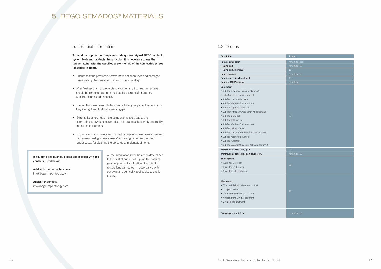
2.1.4
Removable prostheses
Sub-Tec gold cast-on
Sub-Tec gold cast-on no Hex
Sub-Tec magnetic abutment
Sub-Tec bar abutment,
Wirobond® MI or titanium
Sub-Tec 2Locator®abutment
Sub-Tec ball attachment
3.1 Examples of restoration with BEGO Semados® S- or RI-Line (Supra system)
4.1 Examples of restoration with BEGO Semados® Mini-Line
Sub-Tec Universal
Sub-Tec Universal no Hex
2.1.3
Secondary connectionTransmucosal connecting part
Wirobond® MI Mini abutment, conical –
for restoration of narrow anterior gaps
following loss of incisors 12, 22, 32, 31, 41 and 42
(only on Mini 2.9 and / or 3.1 mm)
Mini ball attachment 1.5 / 4.0 mm
(only on Mini 2.9 and / or 3.1 mm)
Mini gold bar abutment
Wirobond® MI
Mini bar abutment
2.1 Examples of restoration with BEGO Semados® S or RI-Line (Sub system)
Secondary connection 1.2 mm
(set)
Sub-Tec titanium abutment, conical
Sub-TecPlus abutment, Wirobond® MI or titanium
Sub-TecPlus angulated abutment 15° or 20°
Wirobond® MI or titanium
2Locator® is a registered trademark of Zest Anchors Inc., CA, USA
Supra-Tec Universal
Supra-Tec gold cast-on
Supra-Tec ball attachment
16 17
5. BEGO SEMADOS® MATERIALS
5.1 General information
To avoid damage to the components, always use original BEGO Implant
system tools and products. In particular, it is necessary to use the
torque ratchet with the specifi ed pretensioning of the connecting screws
(specifi ed in Ncm).
• Ensure that the prosthesis screws have not been used and damaged
previously by the dental technician in the laboratory.
• After fi nal securing of the implant abutments, all connecting screws
should be tightened again to the specifi ed torque after approx.
5 to 10 minutes and checked.
• The implant-prosthesis interfaces must be regularly checked to ensure
they are tight and that there are no gaps.
• Extreme loads exerted on the components could cause the
connecting screw(s) to loosen. If so, it is essential to identify and rectify
the cause of loosening.
• In the case of abutments secured with a separate prosthesis screw, we
recommend using a new screw after the original screw has been
undone, e.g. for cleaning the prosthesis / implant abutments.
All the information given has been determined
to the best of our knowledge on the basis of
years of practical application. It applies to
restorations carried out in accordance with
our own, and generally applicable, scientifi c
fi ndings.
Implant cover screw hand-tight / ≤10
Healing post hand-tight / 10
Healing post, individual 15
Impression post hand-tight / 10
Sub-Tec provisional abutment 15
Sub-Tec CAD Positioner hand-tight
Sub system
• Sub-Tec provisional titanium abutment
• BeCe Sub-Tec ceramic abutment
• Sub-Tec titanium abutment
• Sub-Tec Wirobond® MI abutment
• Sub-Tec angulated abutment
• Sub-TecPlus titanium / Wirobond® MI abutments
• Sub-Tec Universal
• Sub-Tec gold cast-on
• Sub-Tec Wirobond® MI laser base
• Sub-Tec ball attachment
• Sub-Tec titanium / Wirobond® MI bar abutment
• Sub-Tec magnetic abutment
• Sub-Tec 2 Locator®
• Sub-Tec CAD / CAM titanium adhesive abutment
30
Transmucosal connecting part 30
Transmucosal connecting part cover screw hand-tight / 10
Supra system
• Supra-Tec Universal
• Supra-Tec gold cast-on
• Supra-Tec ball attachment
25
Mini system
• Wirobond® MI Mini abutment conical
• Mini gold cast-on
• Mini ball attachment 1.5 / 4.0 mm
• Wirobond® MI Mini bar abutment
• Mini gold bar abutment
25
Secondary screw 1.2 mm hand-tight / 10
Description Torque
5.2 Torques
If you have any queries, please get in touch with the
contacts listed below.
Advice for dental technicians
Advice for dentists:
2Locator® is a registered trademark of Zest Anchors Inc., CA, USA
18 19
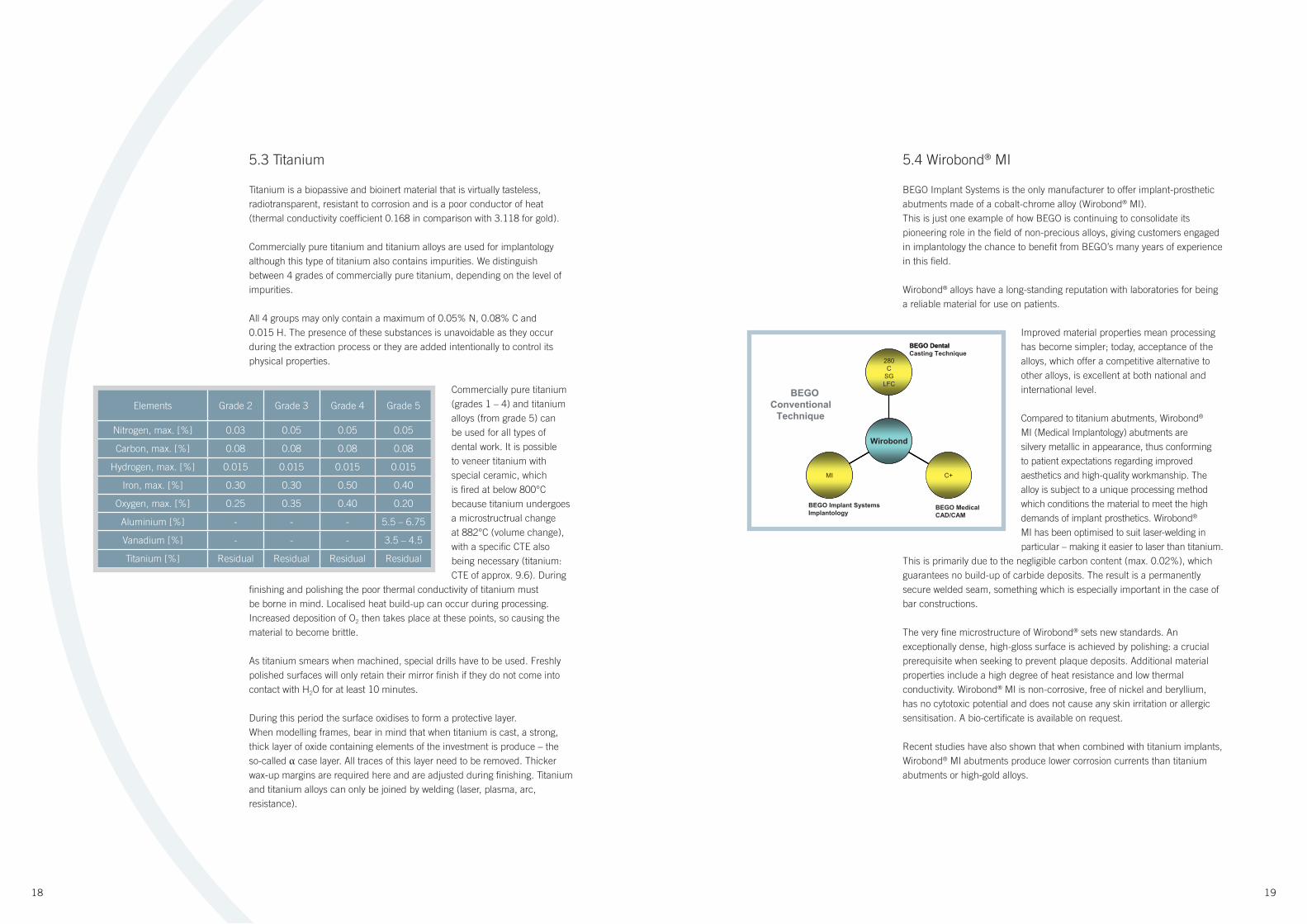
5.3 Titanium
Titanium is a biopassive and bioinert material that is virtually tasteless,
radiotransparent, resistant to corrosion and is a poor conductor of heat
(thermal conductivity coeffi cient 0.168 in comparison with 3.118 for gold).
Commercially pure titanium and titanium alloys are used for implantology
although this type of titanium also contains impurities. We distinguish
between 4 grades of commercially pure titanium, depending on the level of
impurities.
All 4 groups may only contain a maximum of 0.05% N, 0.08% C and
0.015 H. The presence of these substances is unavoidable as they occur
during the extraction process or they are added intentionally to control its
physical properties.
Commercially pure titanium
(grades 1 – 4) and titanium
alloys (from grade 5) can
be used for all types of
dental work. It is possible
to veneer titanium with
special ceramic, which
is fi red at below 800°C
because titanium undergoes
a microstructrual change
at 882°C (volume change),
with a specifi c CTE also
being necessary (titanium:
CTE of approx. 9.6). During
fi nishing and polishing the poor thermal conductivity of titanium must
be borne in mind. Localised heat build-up can occur during processing.
Increased deposition of O2 then takes place at these points, so causing the
material to become brittle.
As titanium smears when machined, special drills have to be used. Freshly
polished surfaces will only retain their mirror fi nish if they do not come into
contact with H2O for at least 10 minutes.
During this period the surface oxidises to form a protective layer.
When modelling frames, bear in mind that when titanium is cast, a strong,
thick layer of oxide containing elements of the investment is produce – the
so-called α case layer. All traces of this layer need to be removed. Thicker
wax-up margins are required here and are adjusted during fi nishing. Titanium
and titanium alloys can only be joined by welding (laser, plasma, arc,
resistance).
Elements Grade 2 Grade 3 Grade 4 Grade 5
Nitrogen, max. [%] 0.03 0.05 0.05 0.05
Carbon, max. [%] 0.08 0.08 0.08 0.08
Hydrogen, max. [%] 0.015 0.015 0.015 0.015
Iron, max. [%] 0.30 0.30 0.50 0.40
Oxygen, max. [%] 0.25 0.35 0.40 0.20
Aluminium [%] - - - 5.5 – 6.75
Vanadium [%] - - - 3.5 – 4.5
Titanium [%] Residual Residual Residual Residual
MI C+
280CSGLFC
Wirobond
BEGO Implant SystemsImplantology
BEGO MedicalCAD/CAM
BEGOConventional
Technique
BEGO DentalCasting Technique
MI C+
280CSGLFC
Wirobond
MI C+
280CSGLFC
BEGO Dental
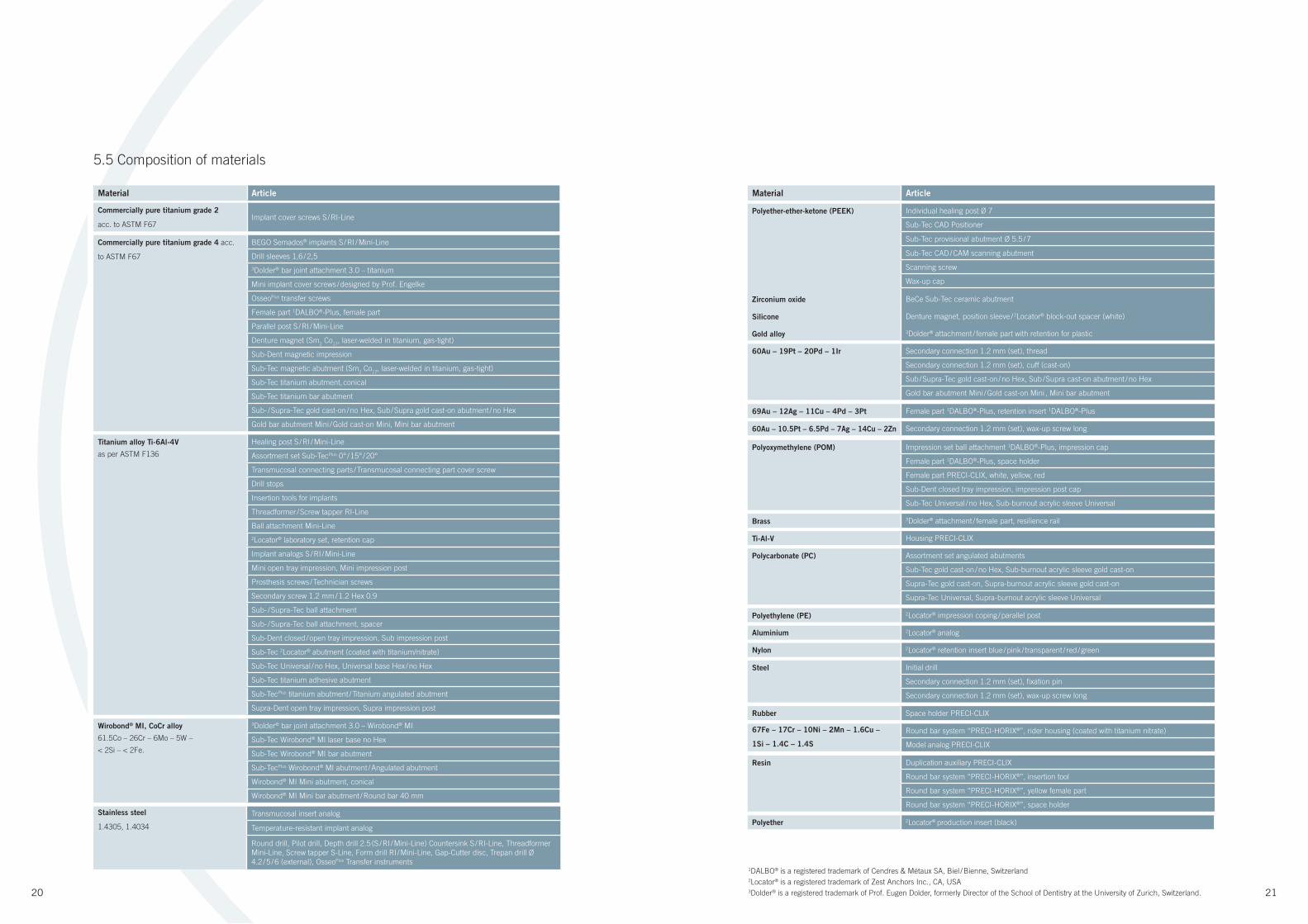
5.4 Wirobond® MI
BEGO Implant Systems is the only manufacturer to offer implant-prosthetic
abutments made of a cobalt-chrome alloy (Wirobond® MI).
This is just one example of how BEGO is continuing to consolidate its
pioneering role in the fi eld of non-precious alloys, giving customers engaged
in implantology the chance to benefi t from BEGO’s many years of experience
in this fi eld.
Wirobond® alloys have a long-standing reputation with laboratories for being
a reliable material for use on patients.
Improved material properties mean processing
has become simpler; today, acceptance of the
alloys, which offer a competitive alternative to
other alloys, is excellent at both national and
international level.
Compared to titanium abutments, Wirobond®
MI (Medical Implantology) abutments are
silvery metallic in appearance, thus conforming
to patient expectations regarding improved
aesthetics and high-quality workmanship. The
alloy is subject to a unique processing method
which conditions the material to meet the high
demands of implant prosthetics. Wirobond®
MI has been optimised to suit laser-welding in
particular – making it easier to laser than titanium.
This is primarily due to the negligible carbon content (max. 0.02%), which
guarantees no build-up of carbide deposits. The result is a permanently
secure welded seam, something which is especially important in the case of
bar constructions.
The very fi ne microstructure of Wirobond® sets new standards. An
exceptionally dense, high-gloss surface is achieved by polishing: a crucial
prerequisite when seeking to prevent plaque deposits. Additional material
properties include a high degree of heat resistance and low thermal
conductivity. Wirobond® MI is non-corrosive, free of nickel and beryllium,
has no cytotoxic potential and does not cause any skin irritation or allergic
sensitisation. A bio-certifi cate is available on request.
Recent studies have also shown that when combined with titanium implants,
Wirobond® MI abutments produce lower corrosion currents than titanium
abutments or high-gold alloys.
20 21
Commercially pure titanium grade 4 acc.
to ASTM F67
BEGO Semados® implants S / RI / Mini-Line
Drill sleeves 1,6 / 2,5
3Dolder® bar joint attachment 3.0 – titanium
Mini implant cover screws / designed by Prof. Engelke
OsseoPlus transfer screws
Female part 1DALBO®-Plus, female part
Parallel post S / RI / Mini-Line
Denture magnet (Sm2 Co
17, laser-welded in titanium, gas-tight)
Sub-Dent magnetic impression
Sub-Tec magnetic abutment (Sm2 Co
17, laser-welded in titanium, gas-tight)
Sub-Tec titanium abutment, conical
Sub-Tec titanium bar abutment
Sub- / Supra-Tec gold cast-on / no Hex, Sub / Supra gold cast-on abutment / no Hex
Gold bar abutment Mini / Gold cast-on Mini, Mini bar abutment
Wirobond® MI, CoCr alloy
61.5Co – 26Cr – 6Mo – 5W –
< 2Si – < 2Fe.
3Dolder® bar joint attachment 3.0 – Wirobond® MI
Sub-Tec Wirobond® MI laser base no Hex
Sub-Tec Wirobond® MI bar abutment
Sub-TecPlus Wirobond® MI abutment / Angulated abutment
Wirobond® MI Mini abutment, conical
Wirobond® MI Mini bar abutment / Round bar 40 mm
Titanium alloy Ti-6Al-4V
as per ASTM F136
Healing post S / RI / Mini-Line
Assortment set Sub-TecPlus 0° / 15° / 20°
Transmucosal connecting parts / Transmucosal connecting part cover screw
Drill stops
Insertion tools for implants
Threadformer / Screw tapper RI-Line
Ball attachment Mini-Line
2Locator® laboratory set, retention cap
Implant analogs S / RI / Mini-Line
Mini open tray impression, Mini impression post
Prosthesis screws / Technician screws
Secondary screw 1.2 mm / 1.2 Hex 0.9
Sub- / Supra-Tec ball attachment
Sub- / Supra-Tec ball attachment, spacer
Sub-Dent closed / open tray impression, Sub impression post
Sub-Tec 2Locator® abutment (coated with titanium/nitrate)
Sub-Tec Universal / no Hex, Universal base Hex / no Hex
Sub-Tec titanium adhesive abutment
Sub-TecPlus titanium abutment / Titanium angulated abutment
Supra-Dent open tray impression, Supra impression post
Commercially pure titanium grade 2
acc. to ASTM F67Implant cover screws S / RI-Line
Material Article
Polyether 2Locator® production insert (black)
Stainless steel
1.4305, 1.4034
Transmucosal insert analog
Temperature-resistant implant analog
Round drill, Pilot drill, Depth drill 2.5 (S / RI / Mini-Line) Countersink S / RI-Line, Threadformer
Mini-Line, Screw tapper S-Line, Form drill RI / Mini-Line, Gap-Cutter disc, Trepan drill Ø
4.2 / 5 / 6 (external), OsseoPlus Transfer instruments
Polyoxymethylene (POM) Impression set ball attachment 1DALBO®-Plus, impression cap
Female part 1DALBO®-Plus, space holder
Female part PRECI-CLIX, white, yellow, red
Sub-Dent closed tray impression, impression post cap
Sub-Tec Universal / no Hex, Sub-burnout acrylic sleeve Universal
Polycarbonate (PC) Assortment set angulated abutments
Sub-Tec gold cast-on / no Hex, Sub-burnout acrylic sleeve gold cast-on
Supra-Tec gold cast-on, Supra-burnout acrylic sleeve gold cast-on
Supra-Tec Universal, Supra-burnout acrylic sleeve Universal
Resin Duplication auxiliary PRECI-CLIX
Round bar system “PRECI-HORIX®”, insertion tool
Round bar system “PRECI-HORIX®”, yellow female part
Round bar system “PRECI-HORIX®”, space holder
Steel Initial drill
Secondary connection 1.2 mm (set), fi xation pin
Secondary connection 1.2 mm (set), wax-up screw long
67Fe – 17Cr – 10Ni – 2Mn – 1.6Cu –
1Si – 1.4C – 1.4S
Round bar system “PRECI-HORIX®”, rider housing (coated with titanium nitrate)
Model analog PRECI-CLIX
60Au – 19Pt – 20Pd – 1Ir Secondary connection 1.2 mm (set), thread
Secondary connection 1.2 mm (set), cuff (cast-on)
Sub / Supra-Tec gold cast-on / no Hex, Sub / Supra cast-on abutment / no Hex
Gold bar abutment Mini / Gold cast-on Mini , Mini bar abutment
Polyether-ether-ketone (PEEK) Individual healing post Ø 7
Sub-Tec CAD Positioner
Sub-Tec provisional abutment Ø 5.5 / 7
Sub-Tec CAD / CAM scanning abutment
Scanning screw
Wax-up cap
Material Article
Silicone Denture magnet, position sleeve / 2Locator® block-out spacer (white)
Zirconium oxide BeCe Sub-Tec ceramic abutment
Brass 3Dolder® attachment / female part, resilience rail
Polyethylene (PE) 2Locator® impression coping / parallel post
69Au – 12Ag – 11Cu – 4Pd – 3Pt Female part 1DALBO®-Plus, retention insert 1DALBO®-Plus
Gold alloy 3Dolder® attachment / female part with retention for plastic
Ti-Al-V Housing PRECI-CLIX
Aluminium 2Locator® analog
Nylon 2Locator® retention insert blue / pink / transparent / red / green
Rubber Space holder PRECI-CLIX
60Au – 10.5Pt – 6.5Pd – 7Ag – 14Cu – 2Zn Secondary connection 1.2 mm (set), wax-up screw long
5.5 Composition of materials
1DALBO® is a registered trademark of Cendres & Métaux SA, Biel / Bienne, Switzerland2Locator® is a registered trademark of Zest Anchors Inc., CA, USA3Dolder® is a registered trademark of Prof. Eugen Dolder, formerly Director of the School of Dentistry at the University of Zurich, Switzerland.
22 23
6. GENERAL PROCESSINGINSTRUCTIONS FOR BEGO SEMADOS®
IMPLANT SUPERSTRUCTURE
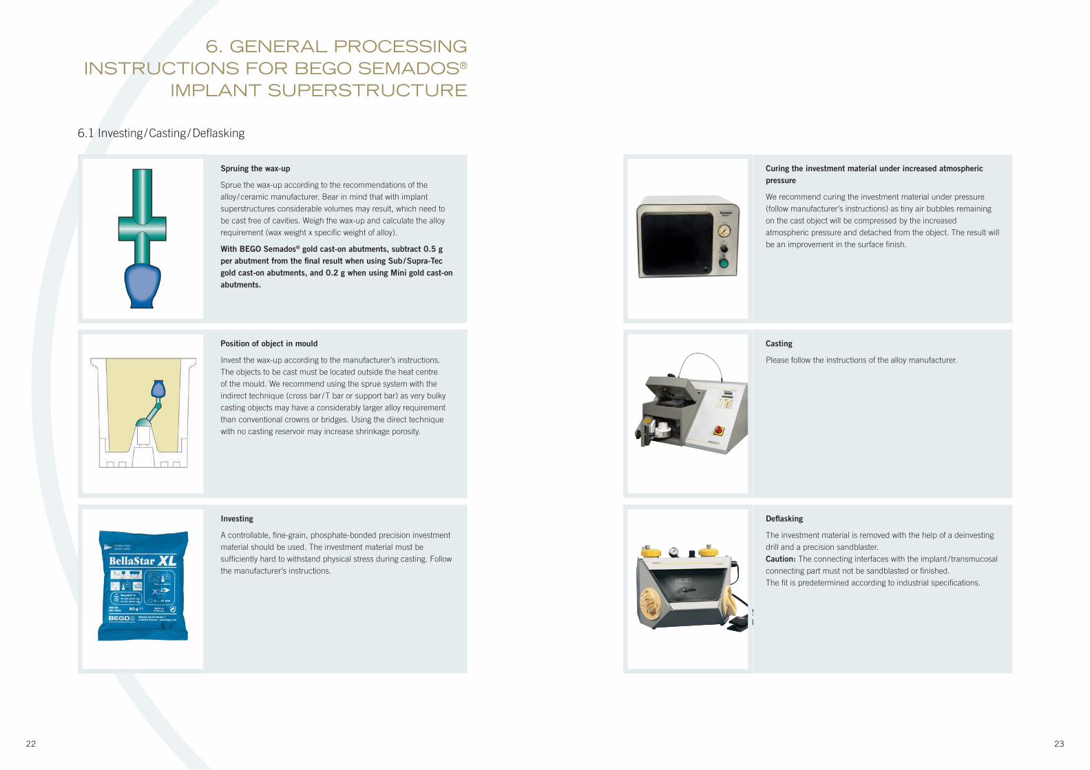
Spruing the wax-up
Sprue the wax-up according to the recommendations of the
alloy / ceramic manufacturer. Bear in mind that with implant
superstructures considerable volumes may result, which need to
be cast free of cavities. Weigh the wax-up and calculate the alloy
requirement (wax weight x specifi c weight of alloy).
With BEGO Semados® gold cast-on abutments, subtract 0.5 g
per abutment from the fi nal result when using Sub / Supra-Tec
gold cast-on abutments, and 0.2 g when using Mini gold cast-on
abutments.
Curing the investment material under increased atmospheric
pressure
We recommend curing the investment material under pressure
(follow manufacturer’s instructions) as tiny air bubbles remaining
on the cast object will be compressed by the increased
atmospheric pressure and detached from the object. The result will
be an improvement in the surface fi nish.
Position of object in mould
Invest the wax-up according to the manufacturer’s instructions.
The objects to be cast must be located outside the heat centre
of the mould. We recommend using the sprue system with the
indirect technique (cross bar / T bar or support bar) as very bulky
casting objects may have a considerably larger alloy requirement
than conventional crowns or bridges. Using the direct technique
with no casting reservoir may increase shrinkage porosity.
Casting
Please follow the instructions of the alloy manufacturer.
Investing
A controllable, fi ne-grain, phosphate-bonded precision investment
material should be used. The investment material must be
suffi ciently hard to withstand physical stress during casting. Follow
the manufacturer’s instructions.
Defl asking
The investment material is removed with the help of a deinvesting
drill and a precision sandblaster.
Caution: The connecting interfaces with the implant / transmucosal
connecting part must not be sandblasted or fi nished.
The fi t is predetermined according to industrial specifi cations.
6.1 Investing / Casting / Defl asking
24 25
Check
When fi tting the frames onto the abutments / implants /
transmucosal connecting parts, ensure that the marginal seal is
gap-free.
Trial fi tting of frame
When fi tting frames, you / the dentist should check correct seating
of the construction. Perform a Sheffi eld test in the patient’s
mouth if required. The Sheffi eld test is the only way of checking
stress-free seating of a superstructure. If correct seating of the
construction cannot be confi rmed with certainty by probing, a
radiographic check should be carried out. The restoration can only
be completed once the fi t has been checked.
Completion and integration
While continuing work, please follow the processing instructions
given by the manufacturers of the materials used.
The prosthesis screw (internal Hex) is always used for the fi nal
insertion of implant abutments which are screwed in place with a
separate screw (tool: hexagon screwdriver 1.25 mm).
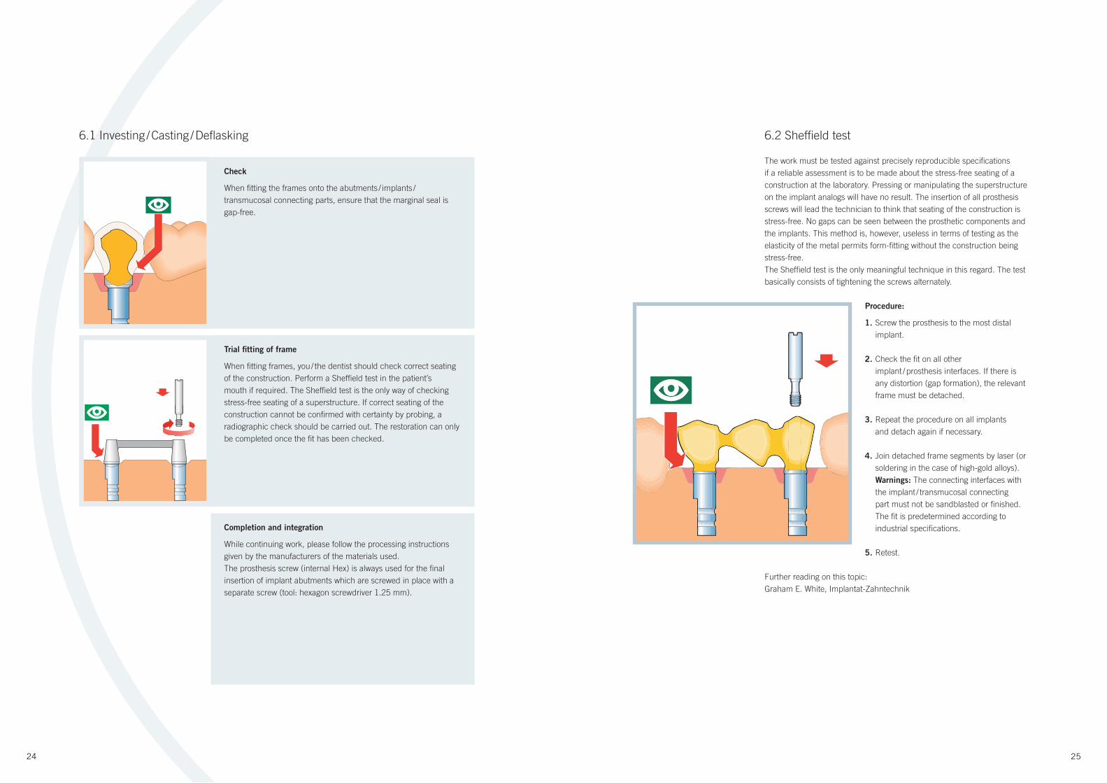
6.2 Sheffi eld test
The work must be tested against precisely reproducible specifi cations
if a reliable assessment is to be made about the stress-free seating of a
construction at the laboratory. Pressing or manipulating the superstructure
on the implant analogs will have no result. The insertion of all prosthesis
screws will lead the technician to think that seating of the construction is
stress-free. No gaps can be seen between the prosthetic components and
the implants. This method is, however, useless in terms of testing as the
elasticity of the metal permits form-fi tting without the construction being
stress-free.
The Sheffield test is the only meaningful technique in this regard. The test
basically consists of tightening the screws alternately.
Procedure:
1. Screw the prosthesis to the most distal
implant.
2. Check the fi t on all other
implant / prosthesis interfaces. If there is
any distortion (gap formation), the relevant
frame must be detached.
3. Repeat the procedure on all implants
and detach again if necessary.
4. Join detached frame segments by laser (or
soldering in the case of high-gold alloys).
Warnings: The connecting interfaces with
the implant / transmucosal connecting
part must not be sandblasted or fi nished.
The fi t is predetermined according to
industrial specifi cations.
5. Retest.
Further reading on this topic:
Graham E. White, Implantat-Zahntechnik
6.1 Investing / Casting / Defl asking
26 27
Rubber dam
It is advisable to use a rubber dam during trial fi ttings and fi nal insertion in
order to protect the patient from possible aspiration of the parts.
Personal expertise
To guarantee personal expertise when producing an implant restoration, we
recommend taking part in a further training course offered by BEGO and / or
studying current specialist literature on this subject.
Processing BEGO Semados® implant components
When using BEGO Semados® implant components, please follow the
methods described in order to preserve the high quality of the parts
supplied. Failure to do so may result in damage, for which BEGO Implant
Systems can accept no liability.
Compatibility
BEGO Semados® implants are not compatible with other implant
systems.
Precautions
Abutments angled more than 30° from the vertical axis of the implant
should not be used. Especially important is proper load distribution.
Please take note of the following: relining of the overdenture after implant
placement to avoid premature loading, passive fi t of the bridge on the
implant abutments, correct adjustment of occlusion with the opposing jaw,
and avoiding excessive transverse loading forces. Implant treatment has
normal contraindications and risks. These are extensively documented in
dental literature.
Follow the instructions for use supplied with each BEGO Semados®
product.
7. GENERAL SAFETY INSTRUCTIONS
8. FABRICATION OF A CUSTOM IMPRESSION TRAY FOR THE
BEGO SEMADOS® SYSTEM
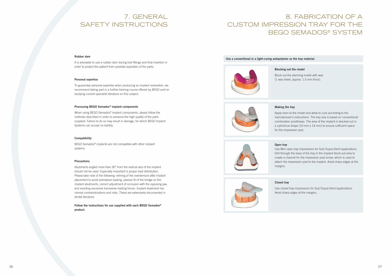
Blocking out the model
Block out the planning model with wax
(1 wax sheet, approx. 1.5 mm thick).
Making the tray
Apply resin to the model and allow to cure according to the
manufacturer’s instructions. The tray size is based on conventional
combination prostheses. The area of the implant is blocked out in
a cylindrical shape (10 mm x 14 mm) to ensure suffi cient space
for the impression post.
Open tray
Use Mini open tray impressions for Sub / Supra-Dent / applications.
Drill through the base of the tray in the implant block-out area to
create a channel for the impression post screw, which is used to
attach the impression post to the implant. Avoid sharp edges at the
margins.
Closed tray
Use closed tray impressions for Sub / Supra-Dent / applications.
Avoid sharp edges at the margins.
Use a conventional or a light-curing autopolymer as the tray material.

28 29
9. FABRICATION OF A DRILL TEMPLATE FOR THE BEGO SEMADOS® SYSTEM
Drilling axis
Align the model with a model table in the milling unit.
Producing the model segments
Saw the model segments through at the marked implant positions.
Positioning hole
Drill the positioning hole with a diameter of 1.2 or 1.5 mm.
Wax-up
Make a wax-up or set-up with prosthetic teeth to replace the
missing tooth units. Take an impression of the situation using
silicone indexes.
Positioning aid
Insert straight wires with the diameter selected (see above) to aid
positioning for the drill sleeves.
Shape of the jawbone
Mark the shape of the jawbone on the model segments. The
thickness of the gingiva is documented beforehand by the dentist by
probing (e.g. needles with depth stop).
Alignment of drill sleeves
Position the 1.6 mm and 2.5 mm drill sleeves.
The basal surface of the sleeves is waxed with the model to
prevent any ingress of resin during polymerisation.
Completion
Make a rail out of light-curing tray material and polymerise the drill
sleeves 2.5 (follow manufacturer’s instructions).
Implant axis
Determine the theoretical implant axis with the help of silicone
indexes. In the best-case scenario the implant axis points to the
central fossa of the respective adjacent tooth.
Only use drill sleeves from the BEGO Semados® system as they have been specially designed for
BEGO Semados® drills (CAUTION: Drills for single use are not suitable here). Drill sleeves from other
implant systems have different dimensions and would damage the drills or lead to inaccurate drilling.
This would result in inferior preparation of the implant bed, possibly jeopardising the success of the
restoration.
9.1 Light-curing autopolymer basis
30 31
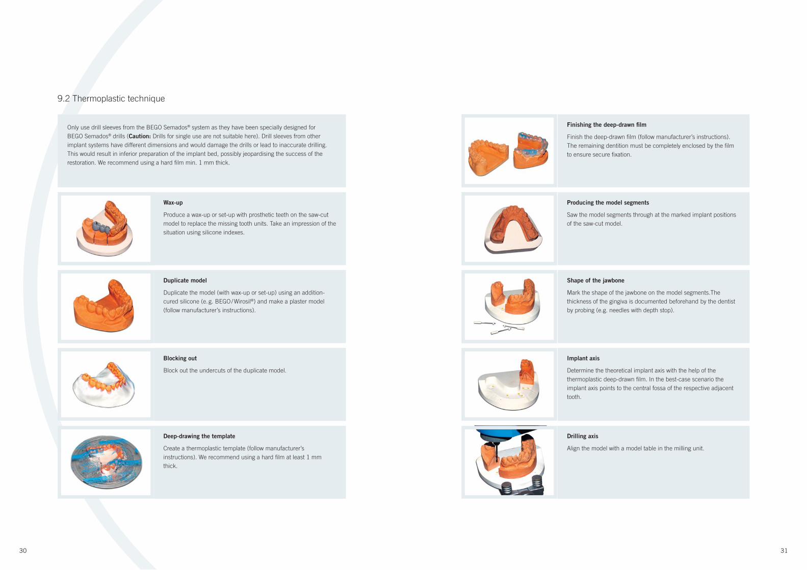
Finishing the deep-drawn fi lm
Finish the deep-drawn fi lm (follow manufacturer’s instructions).
The remaining dentition must be completely enclosed by the fi lm
to ensure secure fi xation.
Wax-up
Produce a wax-up or set-up with prosthetic teeth on the saw-cut
model to replace the missing tooth units. Take an impression of the
situation using silicone indexes.
Producing the model segments
Saw the model segments through at the marked implant positions
of the saw-cut model.
Duplicate model
Duplicate the model (with wax-up or set-up) using an addition-
cured silicone (e. g. BEGO / Wirosil®) and make a plaster model
(follow manufacturer’s instructions).
Shape of the jawbone
Mark the shape of the jawbone on the model segments.The
thickness of the gingiva is documented beforehand by the dentist
by probing (e.g. needles with depth stop).
Blocking out
Block out the undercuts of the duplicate model.
Implant axis
Determine the theoretical implant axis with the help of the
thermoplastic deep-drawn fi lm. In the best-case scenario the
implant axis points to the central fossa of the respective adjacent
tooth.
Drilling axis
Align the model with a model table in the milling unit.
Deep-drawing the template
Create a thermoplastic template (follow manufacturer’s
instructions). We recommend using a hard fi lm at least 1 mm
thick.
Only use drill sleeves from the BEGO Semados® system as they have been specially designed for
BEGO Semados® drills (Caution: Drills for single use are not suitable here). Drill sleeves from other
implant systems have different dimensions and would damage the drills or lead to inaccurate drilling.
This would result in inferior preparation of the implant bed, possibly jeopardising the success of the
restoration. We recommend using a hard fi lm min. 1 mm thick.
9.2 Thermoplastic technique
32 33
10. BEGO SEMADOS® S/RI SUB-DENTCLOSED TRAY IMPRESSIONS
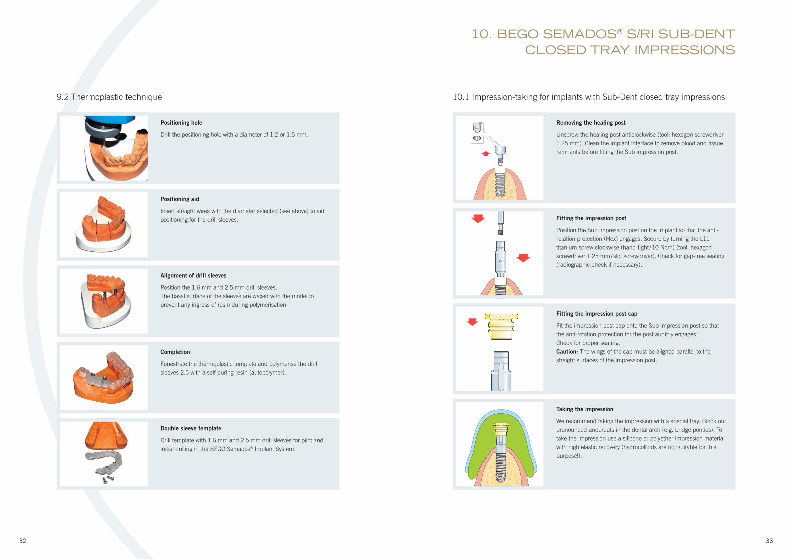
Positioning hole
Drill the positioning hole with a diameter of 1.2 or 1.5 mm.
Positioning aid
Insert straight wires with the diameter selected (see above) to aid
positioning for the drill sleeves.
Alignment of drill sleeves
Position the 1.6 mm and 2.5 mm drill sleeves.
The basal surface of the sleeves are waxed with the model to
prevent any ingress of resin during polymerisation.
Completion
Fenestrate the thermoplastic template and polymerise the drill
sleeves 2.5 with a self-curing resin (autopolymer).
Double sleeve template
Drill template with 1.6 mm and 2.5 mm drill sleeves for pilot and
initial drilling in the BEGO Semados® Implant System.
10.1 Impression-taking for implants with Sub-Dent closed tray impressions
Removing the healing post
Unscrew the healing post anticlockwise (tool: hexagon screwdriver
1.25 mm). Clean the implant interface to remove blood and tissue
remnants before fi tting the Sub impression post.
Fitting the impression post
Position the Sub impression post on the implant so that the anti-
rotation protection (Hex) engages. Secure by turning the L11
titanium screw clockwise (hand-tight / 10 Ncm) (tool: hexagon
screwdriver 1.25 mm / slot screwdriver). Check for gap-free seating
(radiographic check if necessary).
Fitting the impression post cap
Fit the impression post cap onto the Sub impression post so that
the anti-rotation protection for the post audibly engages.
Check for proper seating.
Caution: The wings of the cap must be aligned parallel to the
straight surfaces of the impression post.
Taking the impression
We recommend taking the impression with a special tray. Block out
pronounced undercuts in the dental arch (e.g. bridge pontics). To
take the impression use a silicone or polyether impression material
with high elastic recovery (hydrocolloids are not suitable for this
purpose!).
9.2 Thermoplastic technique
34 35
10.2 Model-making with Sub-Dent closed tray impressions
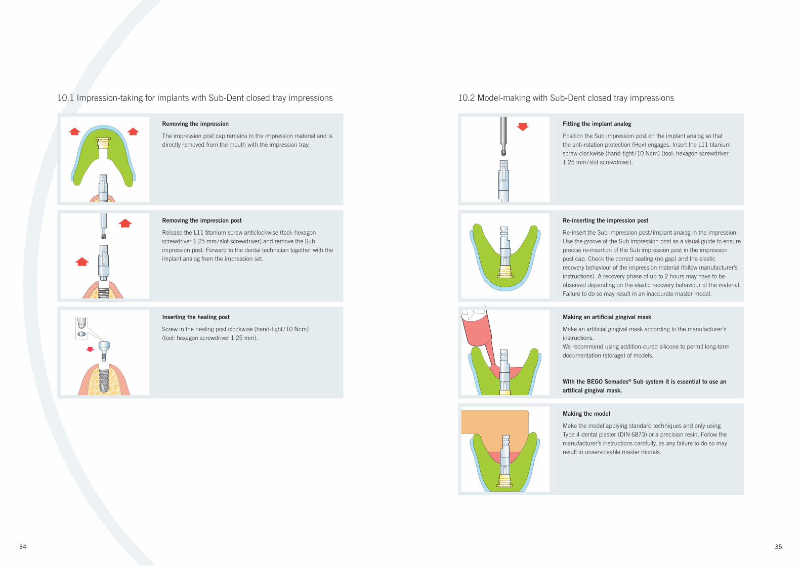
Fitting the implant analog
Position the Sub impression post on the implant analog so that
the anti-rotation protection (Hex) engages. Insert the L11 titanium
screw clockwise (hand-tight / 10 Ncm) (tool: hexagon screwdriver
1.25 mm / slot screwdriver).
Removing the impression
The impression post cap remains in the impression material and is
directly removed from the mouth with the impression tray.
Re-inserting the impression post
Re-insert the Sub impression post / implant analog in the impression.
Use the groove of the Sub impression post as a visual guide to ensure
precise re-insertion of the Sub impression post in the impression
post cap. Check the correct seating (no gap) and the elastic
recovery behaviour of the impression material (follow manufacturer’s
instructions). A recovery phase of up to 2 hours may have to be
observed depending on the elastic recovery behaviour of the material.
Failure to do so may result in an inaccurate master model.
Removing the impression post
Release the L11 titanium screw anticlockwise (tool: hexagon
screwdriver 1.25 mm / slot screwdriver) and remove the Sub
impression post. Forward to the dental technician together with the
implant analog from the impression set.
Making an artifi cial gingival mask
Make an artifi cial gingival mask according to the manufacturer’s
instructions.
We recommend using addition-cured silicone to permit long-term
documentation (storage) of models.
With the BEGO Semados® Sub system it is essential to use an
artifi cal gingival mask.
Inserting the healing post
Screw in the healing post clockwise (hand-tight / 10 Ncm)
(tool: hexagon screwdriver 1.25 mm).
Making the model
Make the model applying standard techniques and only using
Type 4 dental plaster (DIN 6873) or a precision resin. Follow the
manufacturer’s instructions carefully, as any failure to do so may
result in unserviceable master models.
10.1 Impression-taking for implants with Sub-Dent closed tray impressions
36 37
11. BEGO SEMADOS® S/RI SUB-DENTOPEN TRAY IMPRESSIONS
11.1 Impression-taking for implants with Sub-Dent open tray impressions
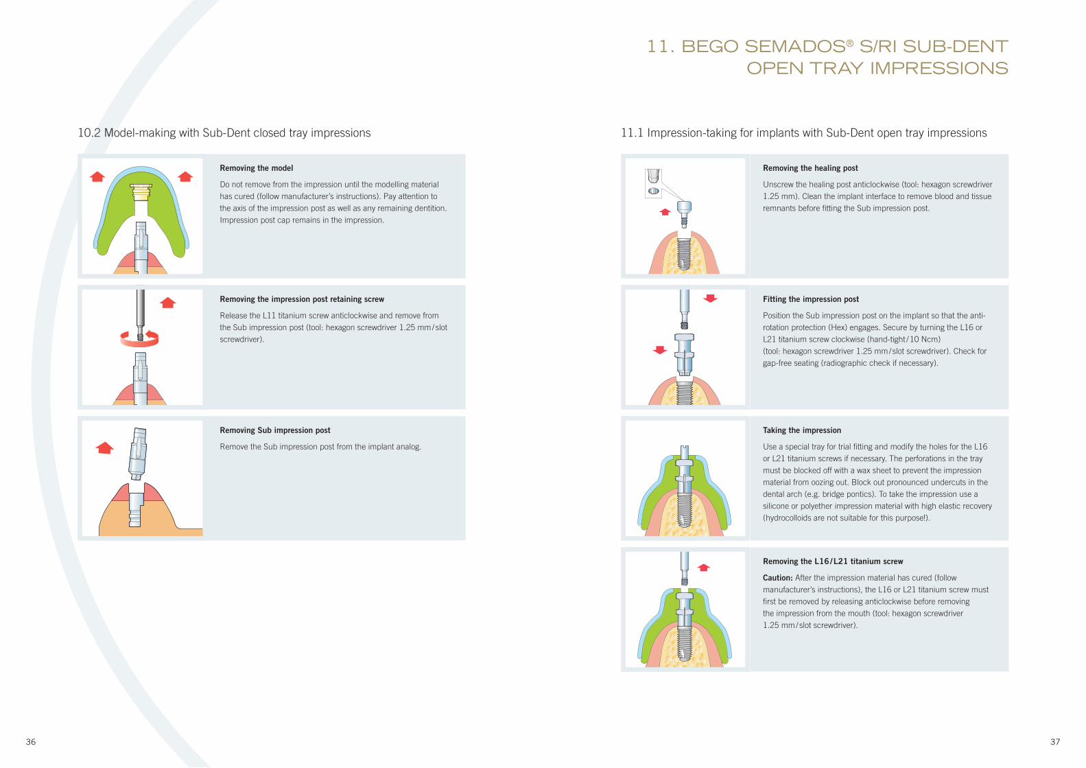
Removing the healing post
Unscrew the healing post anticlockwise (tool: hexagon screwdriver
1.25 mm). Clean the implant interface to remove blood and tissue
remnants before fi tting the Sub impression post.
Removing the model
Do not remove from the impression until the modelling material
has cured (follow manufacturer’s instructions). Pay attention to
the axis of the impression post as well as any remaining dentition.
Impression post cap remains in the impression.
Fitting the impression post
Position the Sub impression post on the implant so that the anti-
rotation protection (Hex) engages. Secure by turning the L16 or
L21 titanium screw clockwise (hand-tight / 10 Ncm)
(tool: hexagon screwdriver 1.25 mm / slot screwdriver). Check for
gap-free seating (radiographic check if necessary).
Removing the impression post retaining screw
Release the L11 titanium screw anticlockwise and remove from
the Sub impression post (tool: hexagon screwdriver 1.25 mm / slot
screwdriver).
Taking the impression
Use a special tray for trial fi tting and modify the holes for the L16
or L21 titanium screws if necessary. The perforations in the tray
must be blocked off with a wax sheet to prevent the impression
material from oozing out. Block out pronounced undercuts in the
dental arch (e.g. bridge pontics). To take the impression use a
silicone or polyether impression material with high elastic recovery
(hydrocolloids are not suitable for this purpose!).
Removing Sub impression post
Remove the Sub impression post from the implant analog.
Removing the L16 / L21 titanium screw
Caution: After the impression material has cured (follow
manufacturer’s instructions), the L16 or L21 titanium screw must
fi rst be removed by releasing anticlockwise before removing
the impression from the mouth (tool: hexagon screwdriver
1.25 mm / slot screwdriver).
10.2 Model-making with Sub-Dent closed tray impressions
38 39
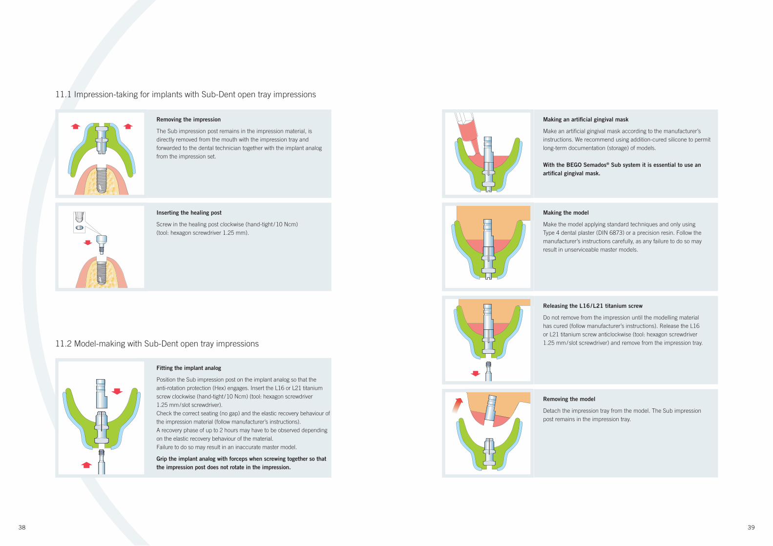
Removing the impression
The Sub impression post remains in the impression material, is
directly removed from the mouth with the impression tray and
forwarded to the dental technician together with the implant analog
from the impression set.
Inserting the healing post
Screw in the healing post clockwise (hand-tight / 10 Ncm)
(tool: hexagon screwdriver 1.25 mm).
11.1 Impression-taking for implants with Sub-Dent open tray impressions
11.2 Model-making with Sub-Dent open tray impressions
Fitting the implant analog
Position the Sub impression post on the implant analog so that the
anti-rotation protection (Hex) engages. Insert the L16 or L21 titanium
screw clockwise (hand-tight / 10 Ncm) (tool: hexagon screwdriver
1.25 mm / slot screwdriver).
Check the correct seating (no gap) and the elastic recovery behaviour of
the impression material (follow manufacturer’s instructions).
A recovery phase of up to 2 hours may have to be observed depending
on the elastic recovery behaviour of the material.
Failure to do so may result in an inaccurate master model.
Grip the implant analog with forceps when screwing together so that
the impression post does not rotate in the impression.
Making an artifi cial gingival mask
Make an artifi cial gingival mask according to the manufacturer’s
instructions. We recommend using addition-cured silicone to permit
long-term documentation (storage) of models.
With the BEGO Semados® Sub system it is essential to use an
artifi cal gingival mask.
Making the model
Make the model applying standard techniques and only using
Type 4 dental plaster (DIN 6873) or a precision resin. Follow the
manufacturer’s instructions carefully, as any failure to do so may
result in unserviceable master models.
Releasing the L16 / L21 titanium screw
Do not remove from the impression until the modelling material
has cured (follow manufacturer’s instructions). Release the L16
or L21 titanium screw anticlockwise (tool: hexagon screwdriver
1.25 mm / slot screwdriver) and remove from the impression tray.
Removing the model
Detach the impression tray from the model. The Sub impression
post remains in the impression tray.
40 41
12. BEGO SEMADOS® MINI OPEN TRAY IMPRESSION
12.1 Impression-taking for implants with Mini open tray impressions
12.2 Model-making with Mini open tray impressions
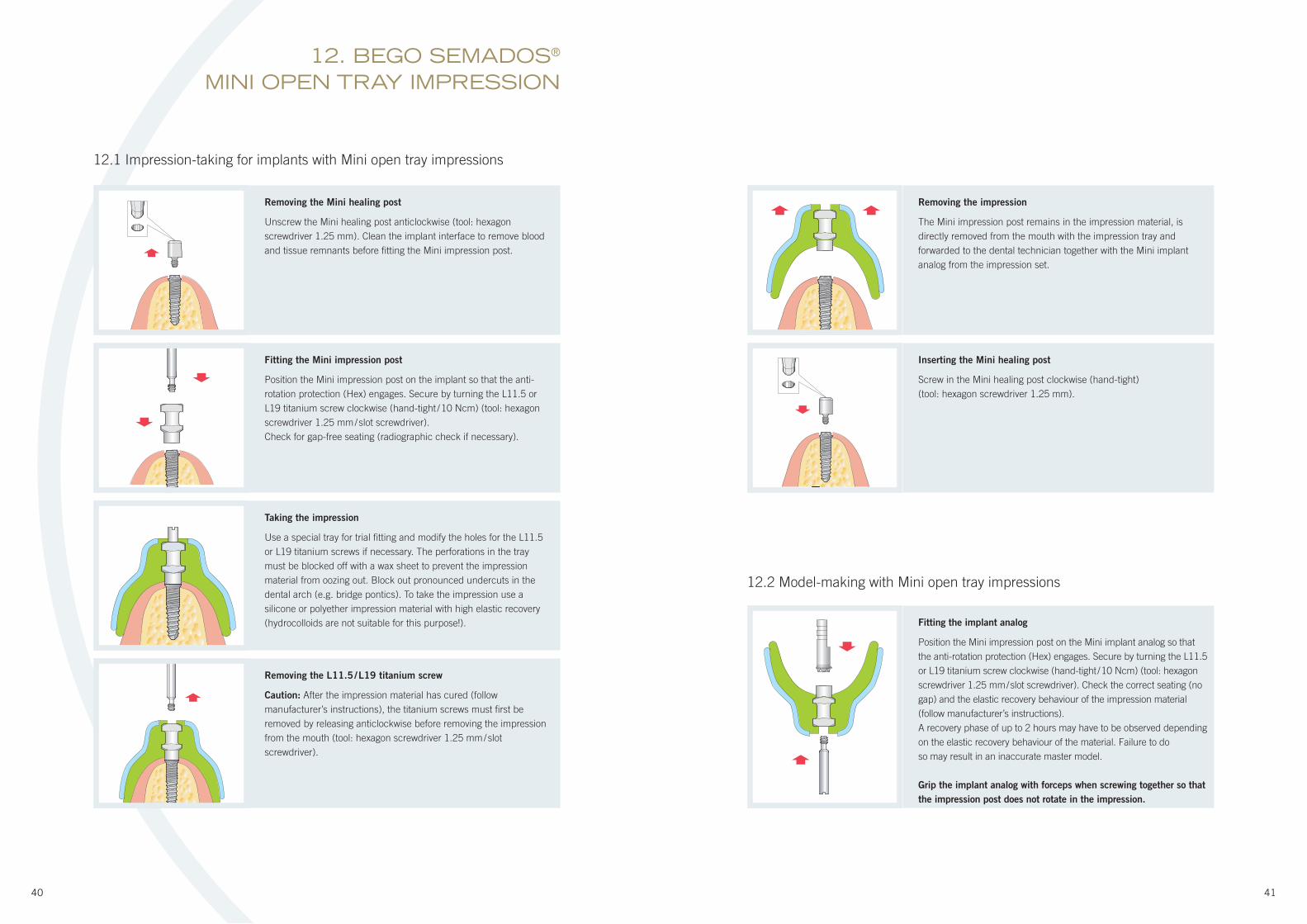
Removing the impression
The Mini impression post remains in the impression material, is
directly removed from the mouth with the impression tray and
forwarded to the dental technician together with the Mini implant
analog from the impression set.
Removing the Mini healing post
Unscrew the Mini healing post anticlockwise (tool: hexagon
screwdriver 1.25 mm). Clean the implant interface to remove blood
and tissue remnants before fi tting the Mini impression post.
Inserting the Mini healing post
Screw in the Mini healing post clockwise (hand-tight)
(tool: hexagon screwdriver 1.25 mm).
Fitting the Mini impression post
Position the Mini impression post on the implant so that the anti-
rotation protection (Hex) engages. Secure by turning the L11.5 or
L19 titanium screw clockwise (hand-tight / 10 Ncm) (tool: hexagon
screwdriver 1.25 mm / slot screwdriver).
Check for gap-free seating (radiographic check if necessary).
Taking the impression
Use a special tray for trial fi tting and modify the holes for the L11.5
or L19 titanium screws if necessary. The perforations in the tray
must be blocked off with a wax sheet to prevent the impression
material from oozing out. Block out pronounced undercuts in the
dental arch (e.g. bridge pontics). To take the impression use a
silicone or polyether impression material with high elastic recovery
(hydrocolloids are not suitable for this purpose!).
Removing the L11.5 / L19 titanium screw
Caution: After the impression material has cured (follow
manufacturer’s instructions), the titanium screws must fi rst be
removed by releasing anticlockwise before removing the impression
from the mouth (tool: hexagon screwdriver 1.25 mm / slot
screwdriver).
Fitting the implant analog
Position the Mini impression post on the Mini implant analog so that
the anti-rotation protection (Hex) engages. Secure by turning the L11.5
or L19 titanium screw clockwise (hand-tight / 10 Ncm) (tool: hexagon
screwdriver 1.25 mm / slot screwdriver). Check the correct seating (no
gap) and the elastic recovery behaviour of the impression material
(follow manufacturer’s instructions).
A recovery phase of up to 2 hours may have to be observed depending
on the elastic recovery behaviour of the material. Failure to do
so may result in an inaccurate master model.
Grip the implant analog with forceps when screwing together so that
the impression post does not rotate in the impression.
42 43
13.1 Impression-taking for implants with Supra-Dent closed tray impressions
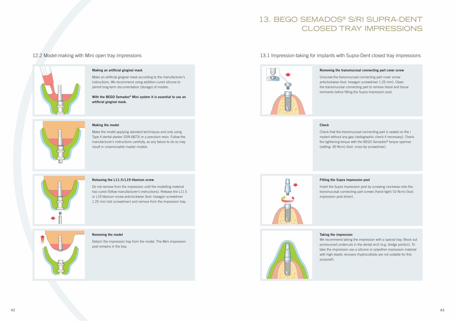
Removing the transmucosal connecting part cover screw
Unscrew the transmucosal connecting part cover screw
anticlockwise (tool: hexagon screwdriver 1.25 mm). Clean
the transmucosal connecting part to remove blood and tissue
remnants before fi tting the Supra impression post.
Check
Check that the transmucosal connecting part is seated on the i
mplant without any gap (radiographic check if necessary). Check
the tightening torque with the BEGO Semados® torque spanner
(setting: 30 Ncm) (tool: cross-tip screwdriver).
Fitting the Supra impression post
Insert the Supra impression post by screwing clockwise onto the
transmucosal connecting part screws (hand-tight / 10 Ncm) (tool:
impression post driver).
Taking the impression
We recommend taking the impression with a special tray. Block out
pronounced undercuts in the dental arch (e.g. bridge pontics). To
take the impression use a silicone or polyether impression material
with high elastic recovery (hydrocolloids are not suitable for this
purpose!).
12.2 Model-making with Mini open tray impressions
Making an artifi cial gingival mask
Make an artifi cial gingival mask according to the manufacturer’s
instructions. We recommend using addition-cured silicone to
permit long-term documentation (storage) of models.
With the BEGO Semados® Mini system it is essential to use an
artifi cial gingival mask.
Making the model
Make the model applying standard techniques and only using
Type 4 dental plaster (DIN 6873) or a precision resin. Follow the
manufacturer’s instructions carefully, as any failure to do so may
result in unserviceable master models.
Releasing the L11.5 / L19 titanium screw
Do not remove from the impression until the modelling material
has cured (follow manufacturer’s instructions). Release the L11.5
or L19 titanium screw anticlockwise (tool: hexagon screwdriver
1.25 mm / slot screwdriver) and remove from the impression tray.
Removing the model
Detach the impression tray from the model. The Mini impression
post remains in the tray.
13. BEGO SEMADOS® S/RI SUPRA-DENTCLOSED TRAY IMPRESSIONS
44 45
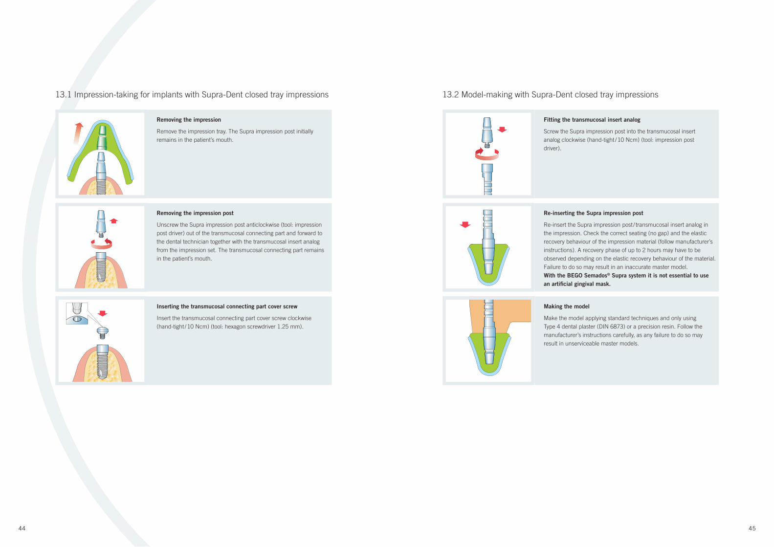
13.2 Model-making with Supra-Dent closed tray impressions
Fitting the transmucosal insert analog
Screw the Supra impression post into the transmucosal insert
analog clockwise (hand-tight / 10 Ncm) (tool: impression post
driver).
Re-inserting the Supra impression post
Re-insert the Supra impression post / transmucosal insert analog in
the impression. Check the correct seating (no gap) and the elastic
recovery behaviour of the impression material (follow manufacturer’s
instructions). A recovery phase of up to 2 hours may have to be
observed depending on the elastic recovery behaviour of the material.
Failure to do so may result in an inaccurate master model.
With the BEGO Semados® Supra system it is not essential to use
an artifi cial gingival mask.
Making the model
Make the model applying standard techniques and only using
Type 4 dental plaster (DIN 6873) or a precision resin. Follow the
manufacturer’s instructions carefully, as any failure to do so may
result in unserviceable master models.
13.1 Impression-taking for implants with Supra-Dent closed tray impressions
Removing the impression
Remove the impression tray. The Supra impression post initially
remains in the patient’s mouth.
Removing the impression post
Unscrew the Supra impression post anticlockwise (tool: impression
post driver) out of the transmucosal connecting part and forward to
the dental technician together with the transmucosal insert analog
from the impression set. The transmucosal connecting part remains
in the patient’s mouth.
Inserting the transmucosal connecting part cover screw
Insert the transmucosal connecting part cover screw clockwise
(hand-tight / 10 Ncm) (tool: hexagon screwdriver 1.25 mm).

46 47
14.1 Impression-taking for implants with Supra-Dent open tray impressions
Removing the transmucosal connecting part cover screw
Unscrew the transmucosal connecting part cover screw
anticlockwise (tool: hexagon screwdriver 1.25 mm). Clean
the transmucosal connecting part to remove blood and tissue
remnants before fi tting the Supra impression post.
Check
Check that the transmucosal connecting part is seated on the
implant without any gap (radiographic check if necessary). Check
the tightening torque with the BEGO Semados® torque spanner
(setting: 30 Ncm) (tool: cross-tip screwdriver).
Fitting the Supra impression post
Position the Supra impression post on the transmucosal
connecting part and secure by turning the L11 or L16 titanium
screw clockwise (hand-tight / 10 Ncm) (tool: hexagon screwdriver
1.25 mm / slot screwdriver). Check for gap-free seating
(radiographic check if necessary).
Taking the impression
Use a special tray for trial fi tting and modify the holes for the L11 or
L21 titanium screw if necessary. The perforations in the tray must be
blocked off with a wax sheet to prevent the impression material from
oozing out. Block out pronounced undercuts in the dental arch (e.g.
bridge pontics). To take the impression use a silicone or polyether
impression material with high elastic recovery (hydrocolloids are not
suitable for this purpose!).
13.2 Model-making with Supra-Dent closed tray impressions
Removing Supra impression post
When the special tray is removed, the impression posts remain
on the model and are then detached from the implant analog by
turning anticlockwise (tool: impression post driver).
14. BEGO SEMADOS® S/RI SUPRA-DENTOPEN TRAY IMPRESSIONS
Removing the model
Do not remove from the impression until the modelling material
has cured (follow manufacturer’s instructions). Pay attention to the
axis of the impression post as well as any remaining dentition.
48 49
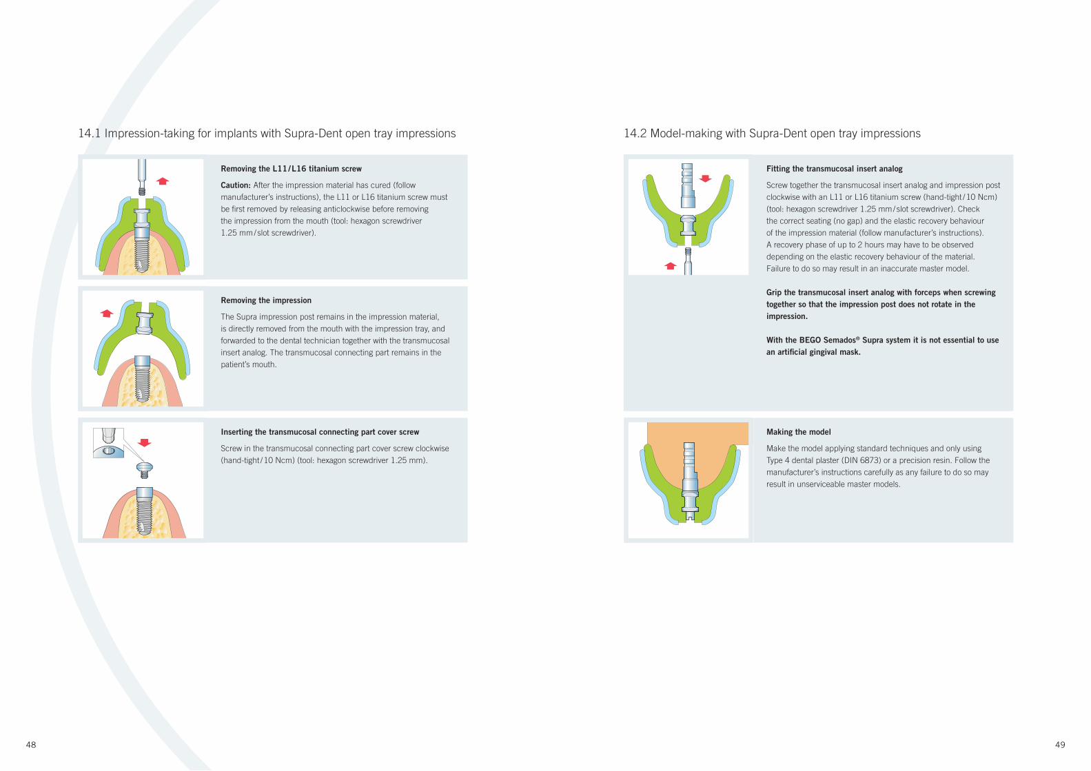
14.2 Model-making with Supra-Dent open tray impressions
Fitting the transmucosal insert analog
Screw together the transmucosal insert analog and impression post
clockwise with an L11 or L16 titanium screw (hand-tight / 10 Ncm)
(tool: hexagon screwdriver 1.25 mm / slot screwdriver). Check
the correct seating (no gap) and the elastic recovery behaviour
of the impression material (follow manufacturer’s instructions).
A recovery phase of up to 2 hours may have to be observed
depending on the elastic recovery behaviour of the material.
Failure to do so may result in an inaccurate master model.
Grip the transmucosal insert analog with forceps when screwing
together so that the impression post does not rotate in the
impression.
With the BEGO Semados® Supra system it is not essential to use
an artifi cial gingival mask.
14.1 Impression-taking for implants with Supra-Dent open tray impressions
Removing the L11 / L16 titanium screw
Caution: After the impression material has cured (follow
manufacturer’s instructions), the L11 or L16 titanium screw must
be fi rst removed by releasing anticlockwise before removing
the impression from the mouth (tool: hexagon screwdriver
1.25 mm / slot screwdriver).
Removing the impression
The Supra impression post remains in the impression material,
is directly removed from the mouth with the impression tray, and
forwarded to the dental technician together with the transmucosal
insert analog. The transmucosal connecting part remains in the
patient’s mouth.
Inserting the transmucosal connecting part cover screw
Screw in the transmucosal connecting part cover screw clockwise
(hand-tight / 10 Ncm) (tool: hexagon screwdriver 1.25 mm).
Making the model
Make the model applying standard techniques and only using
Type 4 dental plaster (DIN 6873) or a precision resin. Follow the
manufacturer’s instructions carefully as any failure to do so may
result in unserviceable master models.
50 51
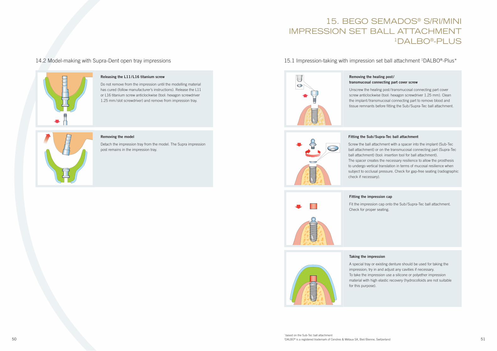
Removing the healing post /
transmucosal connecting part cover screw
Unscrew the healing post / transmucosal connecting part cover
screw anticlockwise (tool: hexagon screwdriver 1.25 mm). Clean
the implant / transmucosal connecting part to remove blood and
tissue remnants before fi tting the Sub / Supra-Tec ball attachment.
Fitting the Sub / Supra-Tec ball attachment
Screw the ball attachment with a spacer into the implant (Sub-Tec
ball attachment) or on the transmucosal connecting part (Supra-Tec
ball attachment) (tool: insertion tool for ball attachment).
The spacer creates the necessary resilience to allow the prosthesis
to undergo vertical translation in terms of mucosal resilience when
subject to occlusal pressure. Check for gap-free seating (radiographic
check if necessary).
Fitting the impression cap
Fit the impression cap onto the Sub / Supra-Tec ball attachment.
Check for proper seating.
Taking the impression
A special tray or existing denture should be used for taking the
impression; try in and adjust any cavities if necessary.
To take the impression use a silicone or polyether impression
material with high elastic recovery (hydrocolloids are not suitable
for this purpose).
Removing the model
Detach the impression tray from the model. The Supra impression
post remains in the impression tray.
15.1 Impression-taking with impression set ball attachment 1DALBO®-Plus*14.2 Model-making with Supra-Dent open tray impressions
15. BEGO SEMADOS® S/RI/MINIIMPRESSION SET BALL ATTACHMENT
1DALBO®-PLUS
Releasing the L11 / L16 titanium screw
Do not remove from the impression until the modelling material
has cured (follow manufacturer’s instructions). Release the L11
or L16 titanium screw anticlockwise (tool: hexagon screwdriver
1.25 mm / slot screwdriver) and remove from impression tray.
* based on the Sub-Tec ball attachment1DALBO® is a registered trademark of Cendres & Métaux SA, Biel / Bienne, Switzerland
52 53
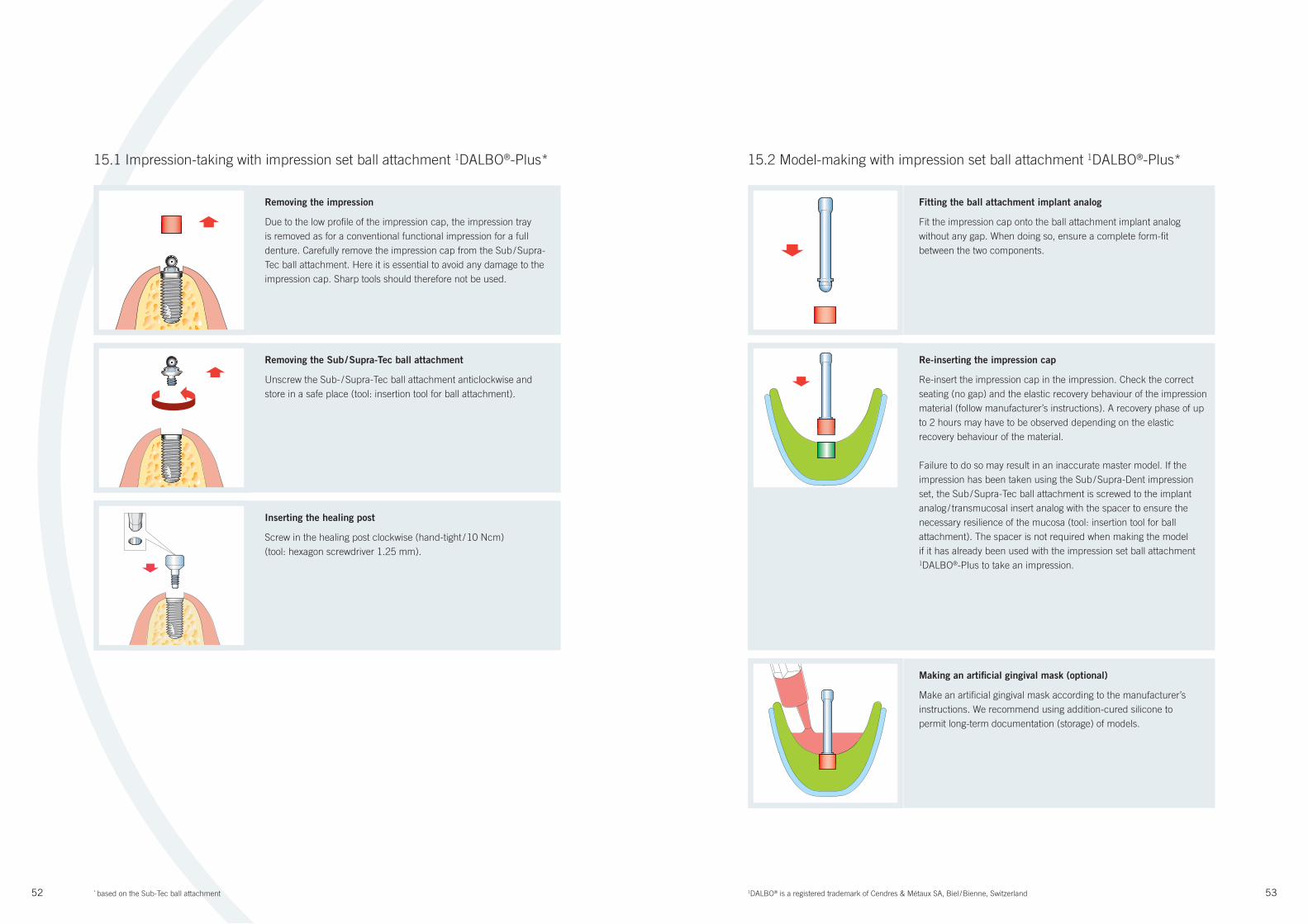
15.2 Model-making with impression set ball attachment 1DALBO®-Plus*
Fitting the ball attachment implant analog
Fit the impression cap onto the ball attachment implant analog
without any gap. When doing so, ensure a complete form-fi t
between the two components.
Making an artifi cial gingival mask (optional)
Make an artifi cial gingival mask according to the manufacturer’s
instructions. We recommend using addition-cured silicone to
permit long-term documentation (storage) of models.
15.1 Impression-taking with impression set ball attachment 1DALBO®-Plus*
Removing the impression
Due to the low profi le of the impression cap, the impression tray
is removed as for a conventional functional impression for a full
denture. Carefully remove the impression cap from the Sub / Supra-
Tec ball attachment. Here it is essential to avoid any damage to the
impression cap. Sharp tools should therefore not be used.
Removing the Sub / Supra-Tec ball attachment
Unscrew the Sub- / Supra-Tec ball attachment anticlockwise and
store in a safe place (tool: insertion tool for ball attachment).
Inserting the healing post
Screw in the healing post clockwise (hand-tight / 10 Ncm)
(tool: hexagon screwdriver 1.25 mm).
Re-inserting the impression cap
Re-insert the impression cap in the impression. Check the correct
seating (no gap) and the elastic recovery behaviour of the impression
material (follow manufacturer’s instructions). A recovery phase of up
to 2 hours may have to be observed depending on the elastic
recovery behaviour of the material.
Failure to do so may result in an inaccurate master model. If the
impression has been taken using the Sub / Supra-Dent impression
set, the Sub / Supra-Tec ball attachment is screwed to the implant
analog / transmucosal insert analog with the spacer to ensure the
necessary resilience of the mucosa (tool: insertion tool for ball
attachment). The spacer is not required when making the model
if it has already been used with the impression set ball attachment 1DALBO®-Plus to take an impression.
1DALBO® is a registered trademark of Cendres & Métaux SA, Biel / Bienne, Switzerland* based on the Sub-Tec ball attachment
54 55
16.1 Impression-taking with Sub-Dent magnetic impressions
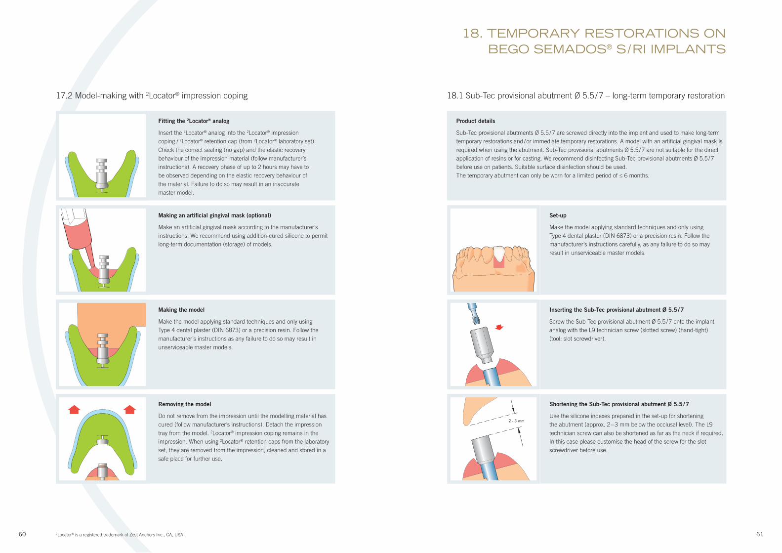
Removing the healing post
Unscrew the healing post anticlockwise (tool: hexagon screwdriver
1.25 mm). Clean the implant interface to remove blood and tissue
remnants before fi tting the Sub impression post.
Taking the impression
We recommend taking the impression with a special tray. To take
the impression use a silicone or polyether impression material
with high elastic recovery (hydrocolloids are not suitable for this
purpose).
15.2 Model-making with impression set ball attachment 1DALBO®-Plus
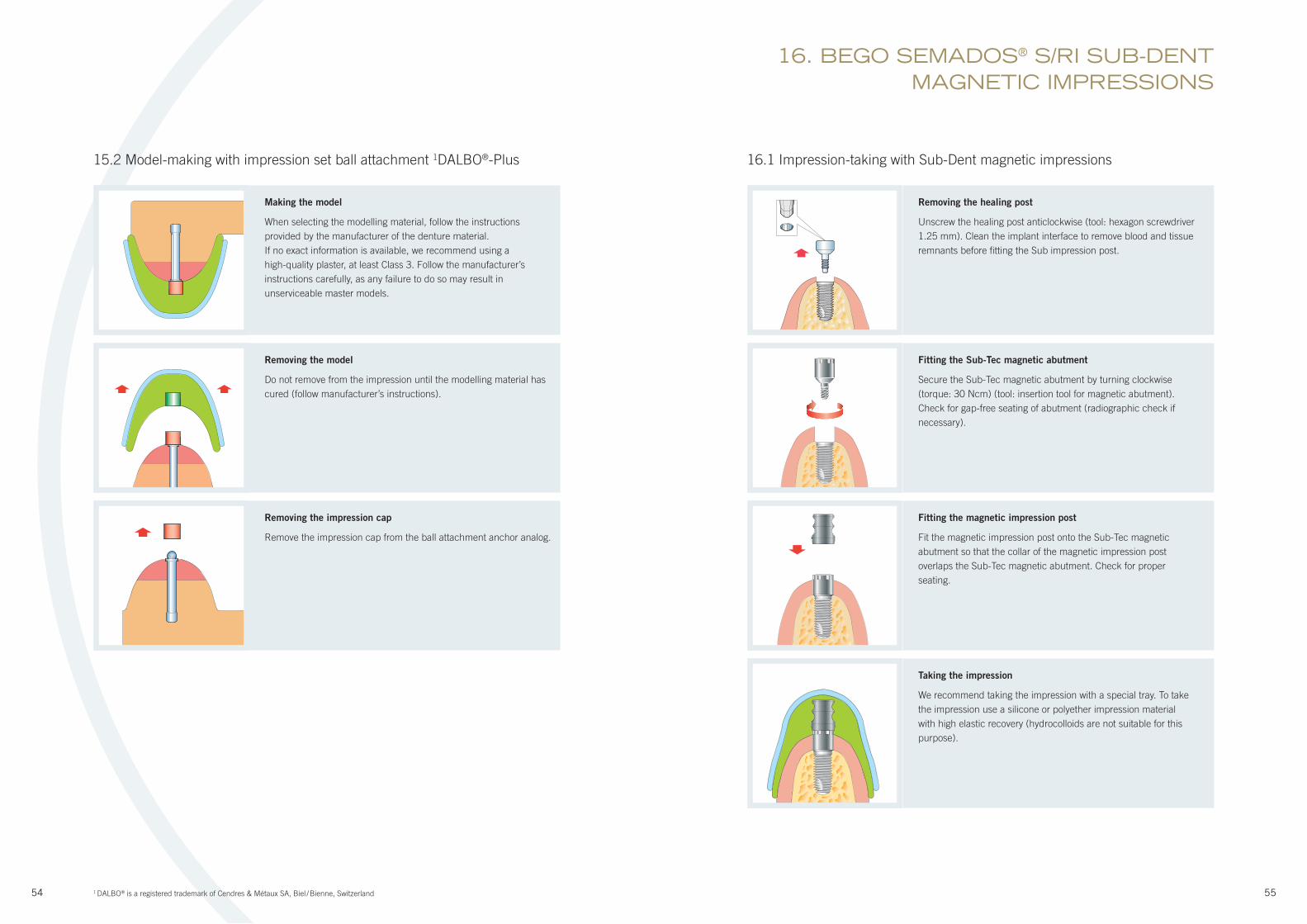
Making the model
When selecting the modelling material, follow the instructions
provided by the manufacturer of the denture material.
If no exact information is available, we recommend using a
high-quality plaster, at least Class 3. Follow the manufacturer’s
instructions carefully, as any failure to do so may result in
unserviceable master models.
Removing the model
Do not remove from the impression until the modelling material has
cured (follow manufacturer’s instructions).
Removing the impression cap
Remove the impression cap from the ball attachment anchor analog.
16. BEGO SEMADOS® S/RI SUB-DENT MAGNETIC IMPRESSIONS
Fitting the Sub-Tec magnetic abutment
Secure the Sub-Tec magnetic abutment by turning clockwise
(torque: 30 Ncm) (tool: insertion tool for magnetic abutment).
Check for gap-free seating of abutment (radiographic check if
necessary).
Fitting the magnetic impression post
Fit the magnetic impression post onto the Sub-Tec magnetic
abutment so that the collar of the magnetic impression post
overlaps the Sub-Tec magnetic abutment. Check for proper
seating.
1 DALBO® is a registered trademark of Cendres & Métaux SA, Biel / Bienne, Switzerland

56 57
16.2 Model-making with Sub-Dent magnetic impressions
Fitting the magnetic model analog
Insert the magnetic model analog into the magnetic impression post.
Check the correct seating (no gap) and the elastic recovery behaviour
of the impression material. A recovery phase of up to 2 hours may
have to be observed depending on the elastic recovery behaviour
of the material. Failure to do so may result in an inaccurate master
model.
When using the BEGO Semados® 4steco® magnetic system,
an artifi cial gingival mask is not essential.
16.1 Impression-taking with Sub-Dent magnetic impressions
Removing the impression
Remove the impression tray. Magnetic impression post remains in
the impression material. The Sub-Tec magnetic abutment remains
in the patient’s mouth. In this case, the healing post is not reused.
Removing the Sub-Tec magnetic abutment (optional)
Unscrew the Sub-Tec magnetic abutment anticlockwise and store
in a safe place (tool: insertion tool for magnetic abutment).
Inserting the healing post (optional)
Screw in the healing post clockwise (hand-tight / 10 Ncm) (tool:
hexagon screwdriver 1.25 mm).
Making the model
Make the model applying standard techniques and only using
Type 4 dental plaster (DIN 6873) or a precision resin. Follow the
manufacturer’s instructions carefully, as any failure to do so may
result in unserviceable master models.
Removing the model
Do not remove from the impression until the modelling material
has cured (follow manufacturer’s instructions). Detach the
impression tray from the model. Impression post remains in the
impression.
4 steco® is a registered trademark of steco-system-technik GmbH & Co. KG, Hamburg, Germany

58 59
Removing the impression
Remove the impression tray. 2Locator® impression coping
remains in the impression material.
Removing the Sub-Tec 2Locator® abutment
Unscrew the Sub-Tec 2Locator® abutment anticlockwise and store in
a safe place (tool: insertion tool for 2Locator®).
Inserting the healing post
Screw in the healing post clockwise (hand-tight / 10 Ncm)
(tool: hexagon screwdriver 1.25 mm).
17.1 Impression-taking with 2Locator® impression coping
Removing the healing post
Unscrew the healing post anticlockwise (tool: hexagon screwdriver
1.25 mm). Clean the implant interface to remove blood and tissue
remnants before fi tting the Sub-Tec 2Locator®.
Fitting the Sub-Tec 2Locator®
First determine the gingival height in order to select the appropriate
Sub-Tec 2Locator® abutment. The retention section (R) must never
be below the gingiva. Secure the 2Locator® by turning clockwise
(torque: 30 Ncm) (tool: 2Locator® insertion tool). Check for gap-free
seating of abutment (radiographic check if necessary).
RG
Fitting the 2Locator® impression coping
Fit the 2Locator® impression coping onto the Sub-Tec 2Locator®
abutment. Check for proper seating.
Taking the impression
A special tray or existing denture should be used for taking the
impression; try in and modify if necessary. For a small denture base,
the retention caps from the 2Locator® laboratory set can also be used
in conjunction with the 2Locator® production insert (Caution: retention
in the impression material is reduced). To take the impression use a
silicone or polyether impression material with high elastic recovery
(hydrocolloids are not suitable for this purpose).
17. BEGO SEMADOS® S/RI 2LOCATOR® IMPRESSIONS
2Locator® is a registered trademark of Zest Anchors Inc., CA, USA
60 61
17.2 Model-making with 2Locator® impression coping
Fitting the 2Locator® analog
Insert the 2Locator® analog into the 2Locator® impression
coping / 2Locator® retention cap (from 2Locator® laboratory set).
Check the correct seating (no gap) and the elastic recovery
behaviour of the impression material (follow manufacturer’s
instructions). A recovery phase of up to 2 hours may have to
be observed depending on the elastic recovery behaviour of
the material. Failure to do so may result in an inaccurate
master model.
Making an artifi cial gingival mask (optional)
Make an artifi cial gingival mask according to the manufacturer’s
instructions. We recommend using addition-cured silicone to permit
long-term documentation (storage) of models.
Making the model
Make the model applying standard techniques and only using
Type 4 dental plaster (DIN 6873) or a precision resin. Follow the
manufacturer’s instructions as any failure to do so may result in
unserviceable master models.
Removing the model
Do not remove from the impression until the modelling material has
cured (follow manufacturer’s instructions). Detach the impression
tray from the model. 2Locator® impression coping remains in the
impression. When using 2Locator® retention caps from the laboratory
set, they are removed from the impression, cleaned and stored in a
safe place for further use.
18.1 Sub-Tec provisional abutment Ø 5.5 / 7 – long-term temporary restoration
Product details
Sub-Tec provisional abutments Ø 5.5 / 7 are screwed directly into the implant and used to make long-term
temporary restorations and / or immediate temporary restorations. A model with an artifi cial gingival mask is
required when using the abutment. Sub-Tec provisional abutments Ø 5.5 / 7 are not suitable for the direct
application of resins or for casting. We recommend disinfecting Sub-Tec provisional abutments Ø 5.5 / 7
before use on patients. Suitable surface disinfection should be used.
The temporary abutment can only be worn for a limited period of ≤ 6 months.
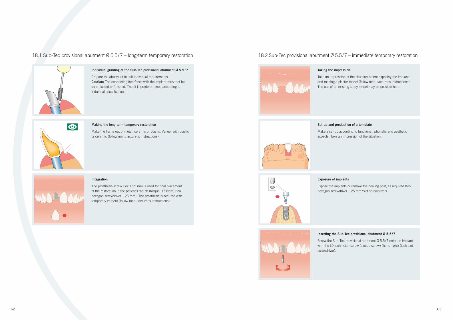
Set-up
Make the model applying standard techniques and only using
Type 4 dental plaster (DIN 6873) or a precision resin. Follow the
manufacturer’s instructions carefully, as any failure to do so may
result in unserviceable master models.
Inserting the Sub-Tec provisional abutment Ø 5.5 / 7
Screw the Sub-Tec provisional abutment Ø 5.5 / 7 onto the implant
analog with the L9 technician screw (slotted screw) (hand-tight)
(tool: slot screwdriver).
Shortening the Sub-Tec provisional abutment Ø 5.5 / 7
Use the silicone indexes prepared in the set-up for shortening
the abutment (approx. 2 – 3 mm below the occlusal level). The L9
technician screw can also be shortened as far as the neck if required.
In this case please customise the head of the screw for the slot
screwdriver before use.
2 - 3 mm
18. TEMPORARY RESTORATIONS ON BEGO SEMADOS® S / RI IMPLANTS
2Locator® is a registered trademark of Zest Anchors Inc., CA, USA
62 63
Individual grinding of the Sub-Tec provisional abutment Ø 5.5 / 7
Prepare the abutment to suit individual requirements.
Caution: The connecting interfaces with the implant must not be
sandblasted or fi nished. The fi t is predetermined according to
industrial specifi cations.
Making the long-term temporary restoration
Make the frame out of metal, ceramic or plastic. Veneer with plastic
or ceramic (follow manufacturer’s instructions).
Integration
The prosthesis screw Hex 1.25 mm is used for fi nal placement
of the restoration in the patient’s mouth (torque: 15 Ncm) (tool:
hexagon screwdriver 1.25 mm). The prosthesis is secured with
temporary cement (follow manufacturer’s instructions).
18.2 Sub-Tec provisional abutment Ø 5.5 / 7 – immediate temporary restoration
Taking the impression
Take an impression of the situation before exposing the implants
and making a plaster model (follow manufacturer’s instructions).
The use of an existing study model may be possible here.
Set-up and production of a template
Make a set-up according to functional, phonetic and aesthetic
aspects. Take an impression of the situation.
Exposure of implants
Expose the implants or remove the healing post, as required (tool:
hexagon screwdriver 1.25 mm / slot screwdriver).
Inserting the Sub-Tec provisional abutment Ø 5.5 / 7
Screw the Sub-Tec provisional abutment Ø 5.5 / 7 onto the implant
with the L9 technician screw (slotted screw) (hand-tight) (tool: slot
screwdriver).
18.1 Sub-Tec provisional abutment Ø 5.5 / 7 – long-term temporary restoration
64 65
Individual grinding of the Sub-Tec provisional abutment Ø 5.5 / 7
Equigingival preparation of the abutment should be performed to
suit individual requirements. The L9 technician screw can also
be shortened as far as the neck if required. In this case please
customise the head of the screw for the slot screwdriver before
use.
Making the immediate temporary restoration
Make the immediate temporary restoration by taking an impression
of the set-up using suitable temporary acrylic material (follow
manufacturer’s instructions).
Integration
The prosthesis screw Hex 1.25 mm is used for fi nal placement
of the restoration in the patient’s mouth (torque: 15 Ncm) (tool:
hexagon screwdriver 1.25 mm). The prosthesis is secured with
temporary cement (follow manufacturer’s instructions).
18.2 Sub-Tec provisional abutment Ø 5.5 / 7 – immediate temporary restoration 18.3 Sub-Tec provisional titanium abutment
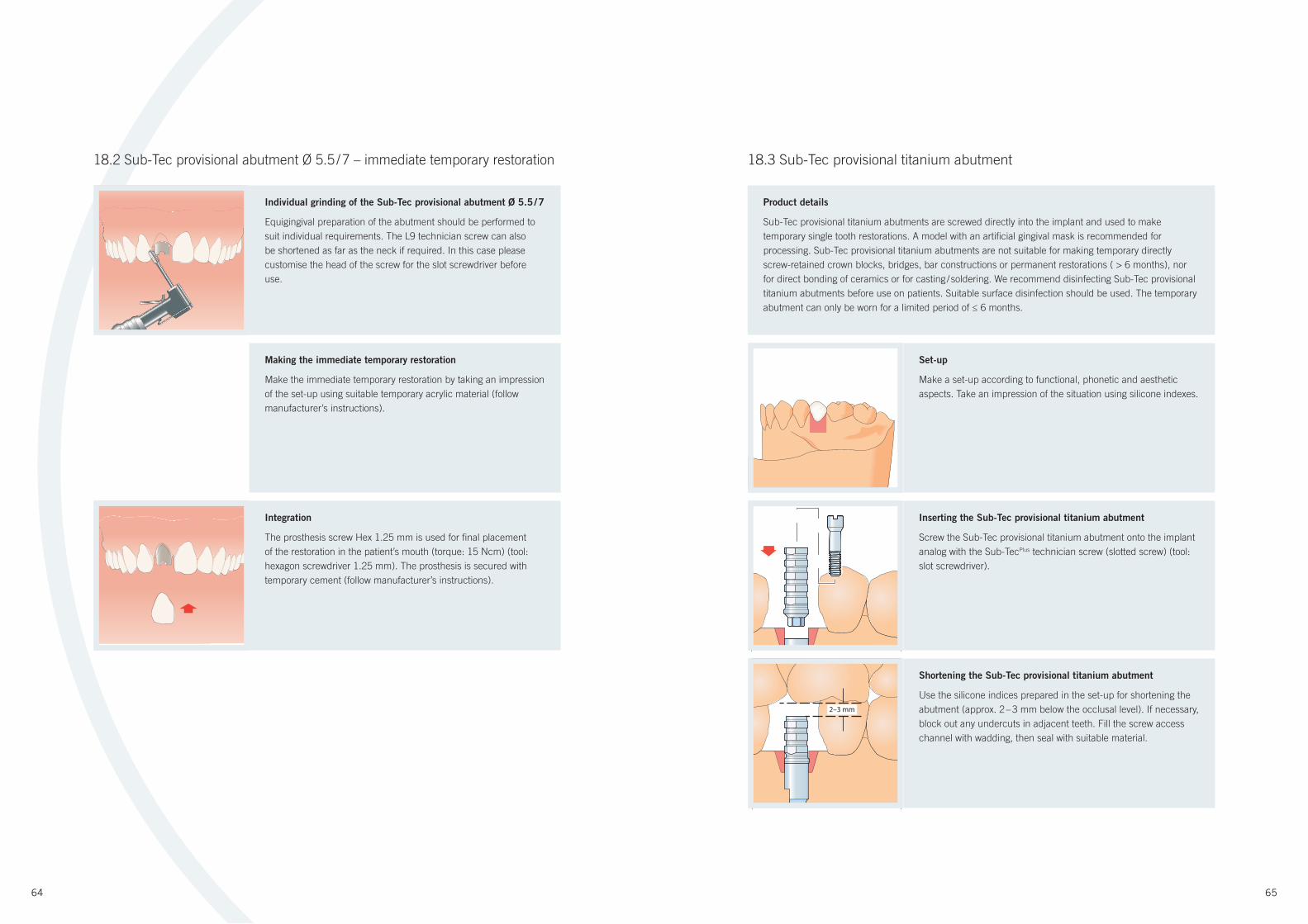
Product details
Sub-Tec provisional titanium abutments are screwed directly into the implant and used to make
temporary single tooth restorations. A model with an artifi cial gingival mask is recommended for
processing. Sub-Tec provisional titanium abutments are not suitable for making temporary directly
screw-retained crown blocks, bridges, bar constructions or permanent restorations ( > 6 months), nor
for direct bonding of ceramics or for casting / soldering. We recommend disinfecting Sub-Tec provisional
titanium abutments before use on patients. Suitable surface disinfection should be used. The temporary
abutment can only be worn for a limited period of ≤ 6 months.
Set-up
Make a set-up according to functional, phonetic and aesthetic
aspects. Take an impression of the situation using silicone indexes.
Inserting the Sub-Tec provisional titanium abutment
Screw the Sub-Tec provisional titanium abutment onto the implant
analog with the Sub-TecPlus technician screw (slotted screw) (tool:
slot screwdriver).
Shortening the Sub-Tec provisional titanium abutment
Use the silicone indices prepared in the set-up for shortening the
abutment (approx. 2 – 3 mm below the occlusal level). If necessary,
block out any undercuts in adjacent teeth. Fill the screw access
channel with wadding, then seal with suitable material.
2–3 mm
66 67
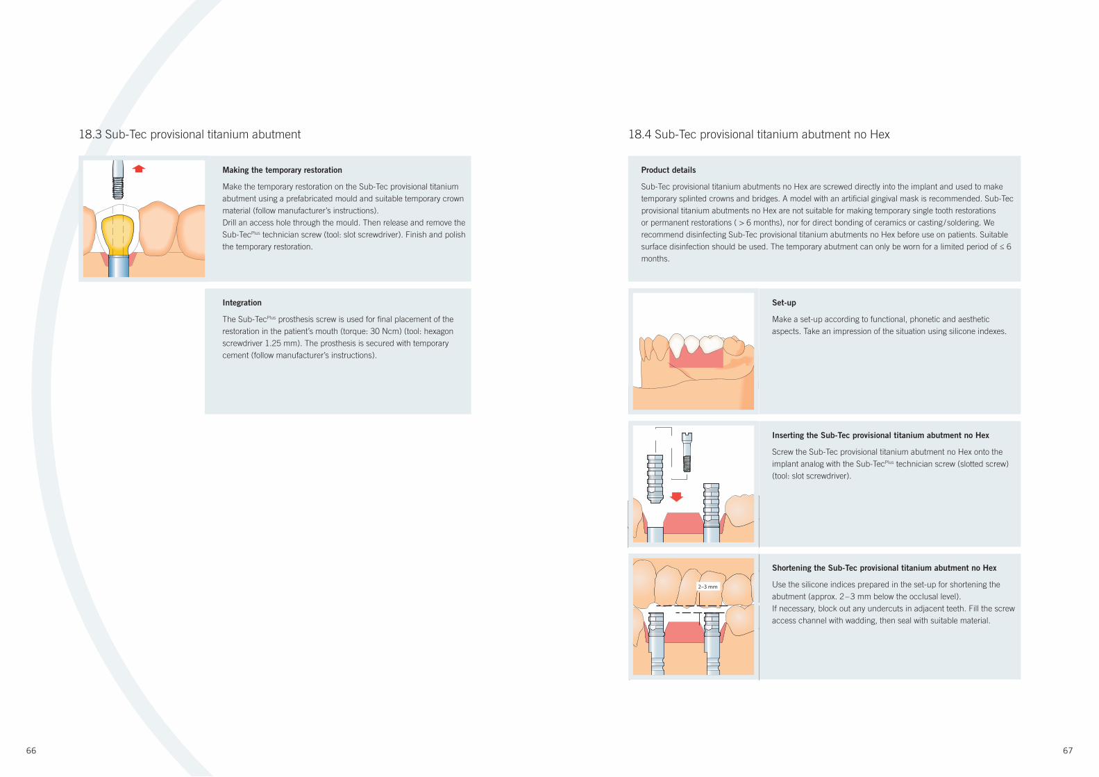
Making the temporary restoration
Make the temporary restoration on the Sub-Tec provisional titanium
abutment using a prefabricated mould and suitable temporary crown
material (follow manufacturer’s instructions).
Drill an access hole through the mould. Then release and remove the
Sub-TecPlus technician screw (tool: slot screwdriver). Finish and polish
the temporary restoration.
Integration
The Sub-TecPlus prosthesis screw is used for fi nal placement of the
restoration in the patient’s mouth (torque: 30 Ncm) (tool: hexagon
screwdriver 1.25 mm). The prosthesis is secured with temporary
cement (follow manufacturer’s instructions).
18.3 Sub-Tec provisional titanium abutment 18.4 Sub-Tec provisional titanium abutment no Hex
Product details
Sub-Tec provisional titanium abutments no Hex are screwed directly into the implant and used to make
temporary splinted crowns and bridges. A model with an artifi cial gingival mask is recommended. Sub-Tec
provisional titanium abutments no Hex are not suitable for making temporary single tooth restorations
or permanent restorations ( > 6 months), nor for direct bonding of ceramics or casting / soldering. We
recommend disinfecting Sub-Tec provisional titanium abutments no Hex before use on patients. Suitable
surface disinfection should be used. The temporary abutment can only be worn for a limited period of ≤ 6
months.
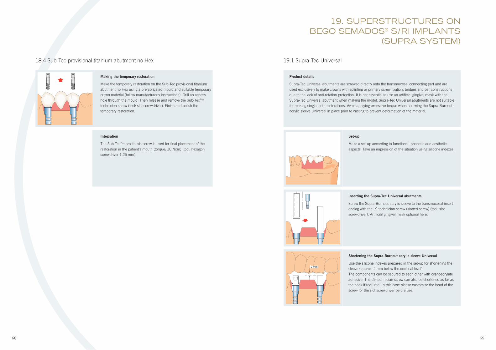
Set-up
Make a set-up according to functional, phonetic and aesthetic
aspects. Take an impression of the situation using silicone indexes.
Inserting the Sub-Tec provisional titanium abutment no Hex
Screw the Sub-Tec provisional titanium abutment no Hex onto the
implant analog with the Sub-TecPlus technician screw (slotted screw)
(tool: slot screwdriver).
Shortening the Sub-Tec provisional titanium abutment no Hex
Use the silicone indices prepared in the set-up for shortening the
abutment (approx. 2 – 3 mm below the occlusal level).
If necessary, block out any undercuts in adjacent teeth. Fill the screw
access channel with wadding, then seal with suitable material.
2–3 mm
68 69
19.1 Supra-Tec Universal
Product details
Supra-Tec Universal abutments are screwed directly onto the transmucosal connecting part and are
used exclusively to make crowns with splinting or primary screw fi xation, bridges and bar constructions
due to the lack of anti-rotation protection. It is not essential to use an artifi cial gingival mask with the
Supra-Tec Universal abutment when making the model. Supra-Tec Universal abutments are not suitable
for making single tooth restorations. Avoid applying excessive torque when screwing the Supra-Burnout
acrylic sleeve Universal in place prior to casting to prevent deformation of the material.
Set-up
Make a set-up according to functional, phonetic and aesthetic
aspects. Take an impression of the situation using silicone indexes.
Inserting the Supra-Tec Universal abutments
Screw the Supra-Burnout acrylic sleeve to the transmucosal insert
analog with the L9 technician screw (slotted screw) (tool: slot
screwdriver). Artifi cial gingival mask optional here.
Shortening the Supra-Burnout acrylic sleeve Universal
Use the silicone indexes prepared in the set-up for shortening the
sleeve (approx. 2 mm below the occlusal level).
The components can be secured to each other with cyanoacrylate
adhesive. The L9 technician screw can also be shortened as far as
the neck if required. In this case please customise the head of the
screw for the slot screwdriver before use.
19. SUPERSTRUCTURES ON BEGO SEMADOS® S / RI IMPLANTS
(SUPRA SYSTEM)
Making the temporary restoration
Make the temporary restoration on the Sub-Tec provisional titanium
abutment no Hex using a prefabricated mould and suitable temporary
crown material (follow manufacturer’s instructions). Drill an access
hole through the mould. Then release and remove the Sub-TecPlus
technician screw (tool: slot screwdriver). Finish and polish the
temporary restoration.
Integration
The Sub-TecPlus prosthesis screw is used for fi nal placement of the
restoration in the patient’s mouth (torque: 30 Ncm) (tool: hexagon
screwdriver 1.25 mm).
18.4 Sub-Tec provisional titanium abutment no Hex
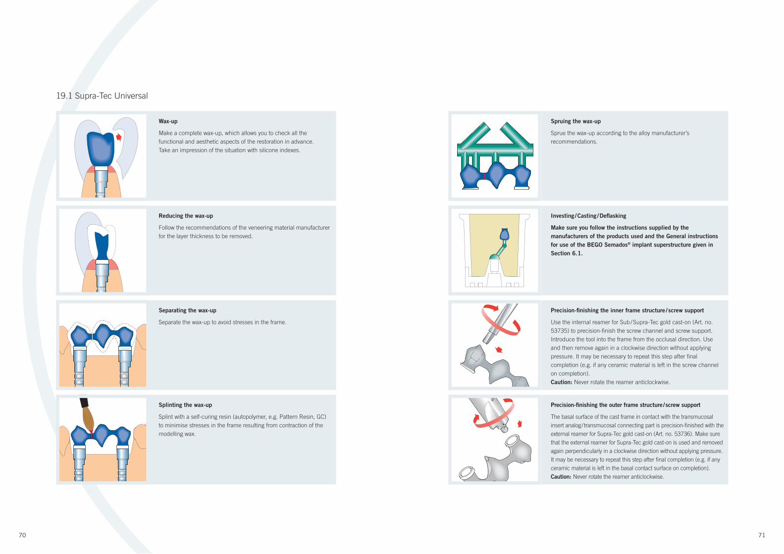
70 71
19.1 Supra-Tec Universal
Spruing the wax-up
Sprue the wax-up according to the alloy manufacturer’s
recommendations.
Wax-up
Make a complete wax-up, which allows you to check all the
functional and aesthetic aspects of the restoration in advance.
Take an impression of the situation with silicone indexes.
Investing / Casting / Defl asking
Make sure you follow the instructions supplied by the
manufacturers of the products used and the General instructions
for use of the BEGO Semados® implant superstructure given in
Section 6.1.
Reducing the wax-up
Follow the recommendations of the veneering material manufacturer
for the layer thickness to be removed.
Precision-fi nishing the inner frame structure / screw support
Use the internal reamer for Sub / Supra-Tec gold cast-on (Art. no.
53735) to precision-fi nish the screw channel and screw support.
Introduce the tool into the frame from the occlusal direction. Use
and then remove again in a clockwise direction without applying
pressure. It may be necessary to repeat this step after fi nal
completion (e.g. if any ceramic material is left in the screw channel
on completion).
Caution: Never rotate the reamer anticlockwise.
Separating the wax-up
Separate the wax-up to avoid stresses in the frame.
Precision-fi nishing the outer frame structure / screw support
The basal surface of the cast frame in contact with the transmucosal
insert analog / transmucosal connecting part is precision-fi nished with the
external reamer for Supra-Tec gold cast-on (Art. no. 53736). Make sure
that the external reamer for Supra-Tec gold cast-on is used and removed
again perpendicularly in a clockwise direction without applying pressure.
It may be necessary to repeat this step after fi nal completion (e.g. if any
ceramic material is left in the basal contact surface on completion).
Caution: Never rotate the reamer anticlockwise.
Splinting the wax-up
Splint with a self-curing resin (autopolymer, e.g. Pattern Resin, GC)
to minimise stresses in the frame resulting from contraction of the
modelling wax.
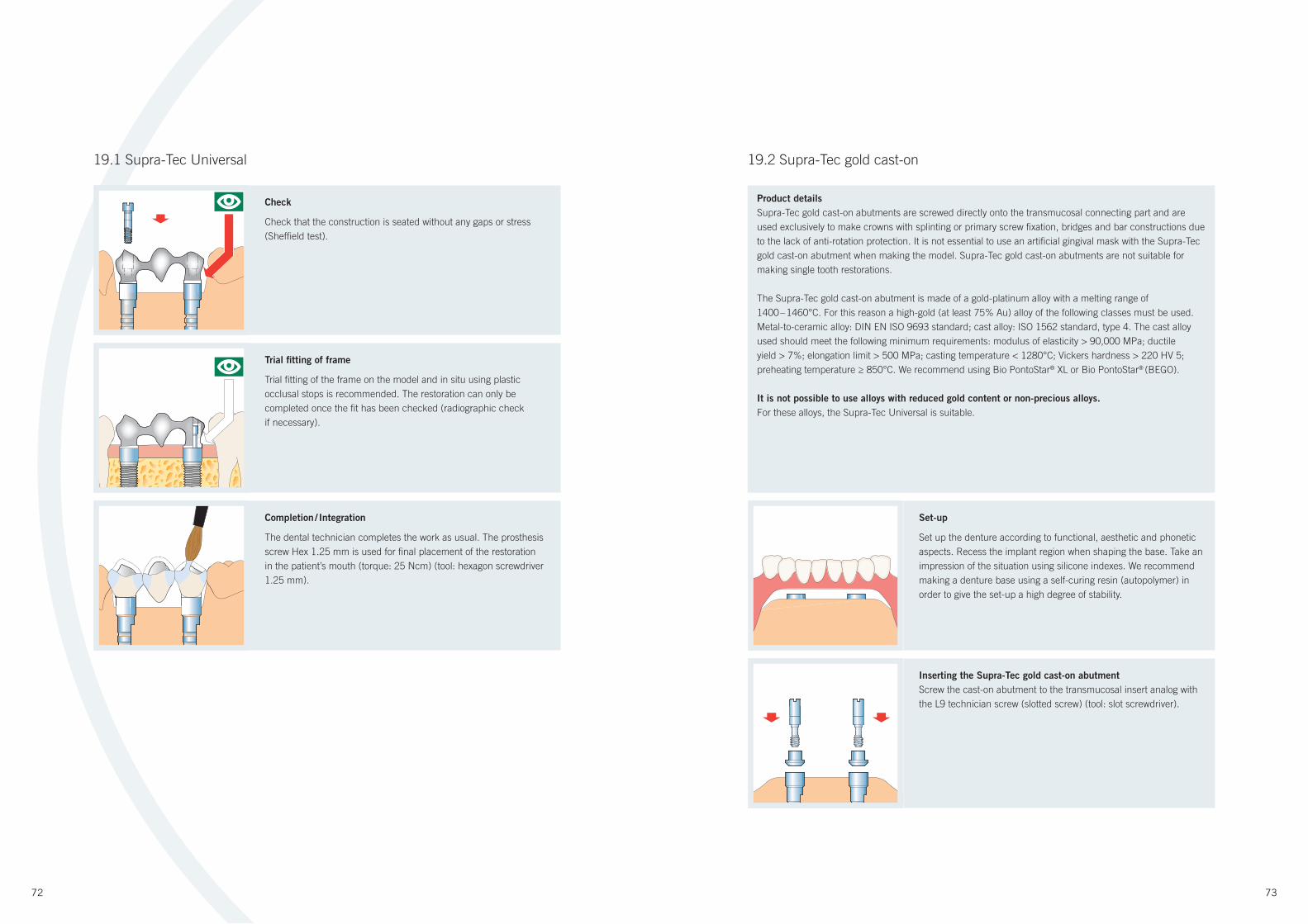
72 73
Check
Check that the construction is seated without any gaps or stress
(Sheffi eld test).
Trial fi tting of frame
Trial fi tting of the frame on the model and in situ using plastic
occlusal stops is recommended. The restoration can only be
completed once the fi t has been checked (radiographic check
if necessary).
Completion / Integration
The dental technician completes the work as usual. The prosthesis
screw Hex 1.25 mm is used for fi nal placement of the restoration
in the patient’s mouth (torque: 25 Ncm) (tool: hexagon screwdriver
1.25 mm).
19.2 Supra-Tec gold cast-on
Product details
Supra-Tec gold cast-on abutments are screwed directly onto the transmucosal connecting part and are
used exclusively to make crowns with splinting or primary screw fi xation, bridges and bar constructions due
to the lack of anti-rotation protection. It is not essential to use an artifi cial gingival mask with the Supra-Tec
gold cast-on abutment when making the model. Supra-Tec gold cast-on abutments are not suitable for
making single tooth restorations.
The Supra-Tec gold cast-on abutment is made of a gold-platinum alloy with a melting range of
1400 – 1460°C. For this reason a high-gold (at least 75% Au) alloy of the following classes must be used.
Metal-to-ceramic alloy: DIN EN ISO 9693 standard; cast alloy: ISO 1562 standard, type 4. The cast alloy
used should meet the following minimum requirements: modulus of elasticity > 90,000 MPa; ductile
yield > 7%; elongation limit > 500 MPa; casting temperature < 1280°C; Vickers hardness > 220 HV 5;
preheating temperature ≥ 850°C. We recommend using Bio PontoStar® XL or Bio PontoStar® (BEGO).
It is not possible to use alloys with reduced gold content or non-precious alloys.
For these alloys, the Supra-Tec Universal is suitable.
Set-up
Set up the denture according to functional, aesthetic and phonetic
aspects. Recess the implant region when shaping the base. Take an
impression of the situation using silicone indexes. We recommend
making a denture base using a self-curing resin (autopolymer) in
order to give the set-up a high degree of stability.
Inserting the Supra-Tec gold cast-on abutment
Screw the cast-on abutment to the transmucosal insert analog with
the L9 technician screw (slotted screw) (tool: slot screwdriver).
19.1 Supra-Tec Universal
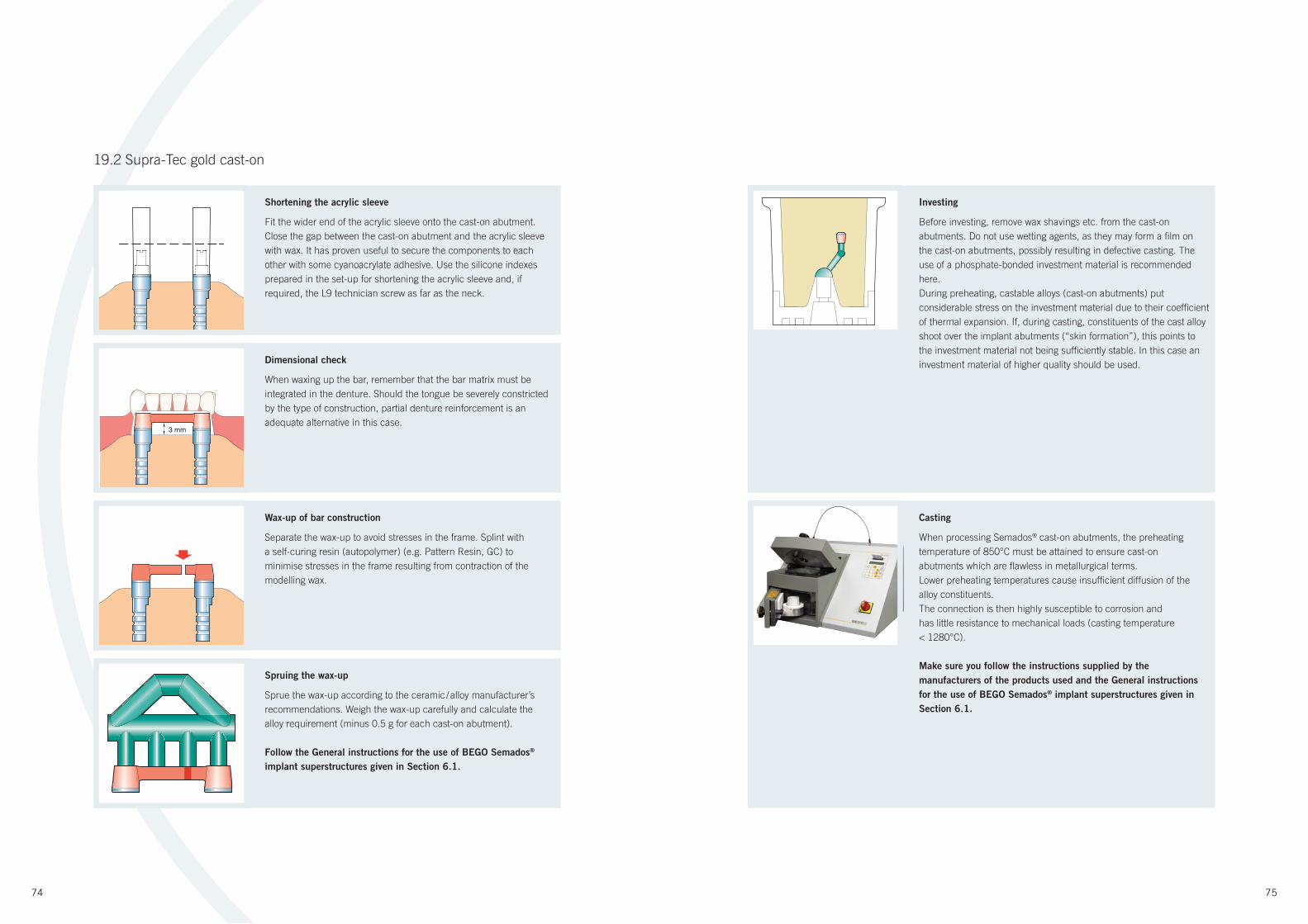
74 75
Shortening the acrylic sleeve
Fit the wider end of the acrylic sleeve onto the cast-on abutment.
Close the gap between the cast-on abutment and the acrylic sleeve
with wax. It has proven useful to secure the components to each
other with some cyanoacrylate adhesive. Use the silicone indexes
prepared in the set-up for shortening the acrylic sleeve and, if
required, the L9 technician screw as far as the neck.
Investing
Before investing, remove wax shavings etc. from the cast-on
abutments. Do not use wetting agents, as they may form a fi lm on
the cast-on abutments, possibly resulting in defective casting. The
use of a phosphate-bonded investment material is recommended
here.
During preheating, castable alloys (cast-on abutments) put
considerable stress on the investment material due to their coeffi cient
of thermal expansion. If, during casting, constituents of the cast alloy
shoot over the implant abutments (“skin formation”), this points to
the investment material not being suffi ciently stable. In this case an
investment material of higher quality should be used.
Dimensional check
When waxing up the bar, remember that the bar matrix must be
integrated in the denture. Should the tongue be severely constricted
by the type of construction, partial denture reinforcement is an
adequate alternative in this case.
Wax-up of bar construction
Separate the wax-up to avoid stresses in the frame. Splint with
a self-curing resin (autopolymer) (e.g. Pattern Resin, GC) to
minimise stresses in the frame resulting from contraction of the
modelling wax.
Casting
When processing Semados® cast-on abutments, the preheating
temperature of 850°C must be attained to ensure cast-on
abutments which are fl awless in metallurgical terms.
Lower preheating temperatures cause insuffi cient diffusion of the
alloy constituents.
The connection is then highly susceptible to corrosion and
has little resistance to mechanical loads (casting temperature
< 1280°C).
Make sure you follow the instructions supplied by the
manufacturers of the products used and the General instructions
for the use of BEGO Semados® implant superstructures given in
Section 6.1.
Spruing the wax-up
Sprue the wax-up according to the ceramic / alloy manufacturer’s
recommendations. Weigh the wax-up carefully and calculate the
alloy requirement (minus 0.5 g for each cast-on abutment).
Follow the General instructions for the use of BEGO Semados®
implant superstructures given in Section 6.1.
19.2 Supra-Tec gold cast-on
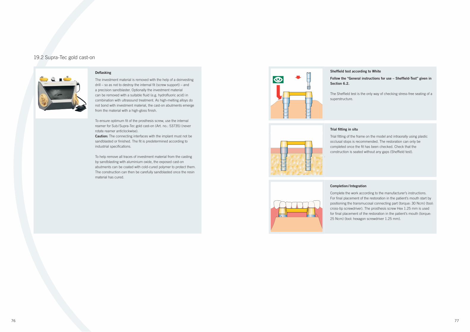
76 77
Defl asking
The investment material is removed with the help of a deinvesting
drill – so as not to destroy the internal fi t (screw support) – and
a precision sandblaster. Optionally the investment material
can be removed with a suitable fl uid (e.g. hydrofl uoric acid) in
combination with ultrasound treatment. As high-melting alloys do
not bond with investment material, the cast-on abutments emerge
from the material with a high-gloss fi nish.
To ensure optimum fi t of the prosthesis screw, use the internal
reamer for Sub / Supra-Tec gold cast-on (Art. no.: 53735) (never
rotate reamer anticlockwise).
Caution: The connecting interfaces with the implant must not be
sandblasted or fi nished. The fi t is predetermined according to
industrial specifi cations.
To help remove all traces of investment material from the casting
by sandblasting with aluminium oxide, the exposed cast-on
abutments can be coated with cold-cured polymer to protect them.
The construction can then be carefully sandblasted once the resin
material has cured.
Trial fi tting in situ
Trial fi tting of the frame on the model and intraorally using plastic
occlusal stops is recommended. The restoration can only be
completed once the fi t has been checked. Check that the
construction is seated without any gaps (Sheffi eld test).
Sheffi eld test according to White
Follow the “General instructions for use – Sheffi eld-Test” given in
Section 6.2.
The Sheffi eld test is the only way of checking stress-free seating of a
superstructure.
Completion / Integration
Complete the work according to the manufacturer’s instructions.
For fi nal placement of the restoration in the patient’s mouth start by
positioning the transmucosal connecting part (torque: 30 Ncm) (tool:
cross-tip screwdriver). The prosthesis screw Hex 1.25 mm is used
for fi nal placement of the restoration in the patient’s mouth (torque:
25 Ncm) (tool: hexagon screwdriver 1.25 mm).
19.2 Supra-Tec gold cast-on
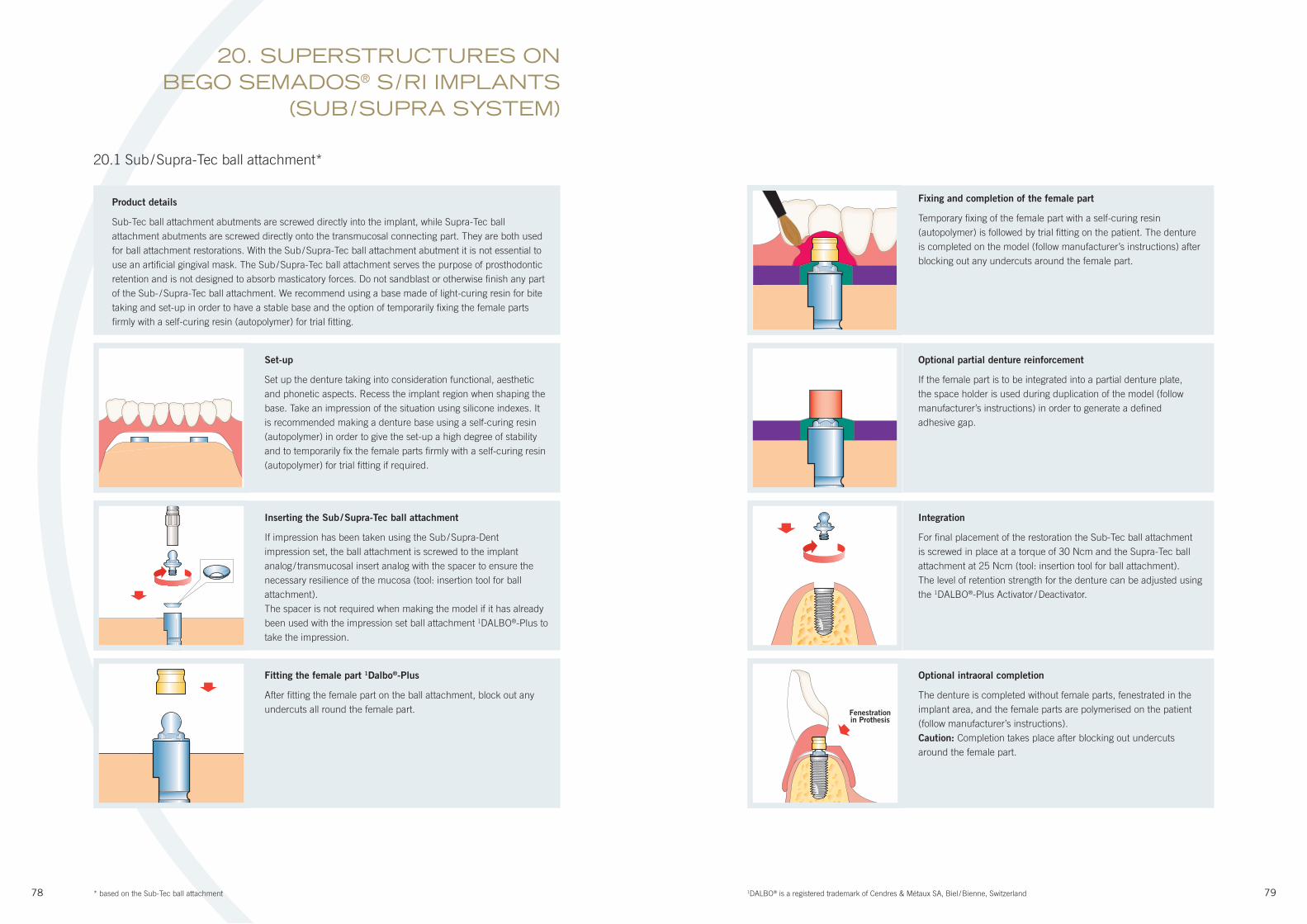
78 79
Product details
Sub-Tec ball attachment abutments are screwed directly into the implant, while Supra-Tec ball
attachment abutments are screwed directly onto the transmucosal connecting part. They are both used
for ball attachment restorations. With the Sub / Supra-Tec ball attachment abutment it is not essential to
use an artifi cial gingival mask. The Sub / Supra-Tec ball attachment serves the purpose of prosthodontic
retention and is not designed to absorb masticatory forces. Do not sandblast or otherwise fi nish any part
of the Sub- / Supra-Tec ball attachment. We recommend using a base made of light-curing resin for bite
taking and set-up in order to have a stable base and the option of temporarily fi xing the female parts
fi rmly with a self-curing resin (autopolymer) for trial fi tting.
Set-up
Set up the denture taking into consideration functional, aesthetic
and phonetic aspects. Recess the implant region when shaping the
base. Take an impression of the situation using silicone indexes. It
is recommended making a denture base using a self-curing resin
(autopolymer) in order to give the set-up a high degree of stability
and to temporarily fi x the female parts fi rmly with a self-curing resin
(autopolymer) for trial fi tting if required.
Inserting the Sub / Supra-Tec ball attachment
If impression has been taken using the Sub / Supra-Dent
impression set, the ball attachment is screwed to the implant
analog / transmucosal insert analog with the spacer to ensure the
necessary resilience of the mucosa (tool: insertion tool for ball
attachment).
The spacer is not required when making the model if it has already
been used with the impression set ball attachment 1DALBO®-Plus to
take the impression.
Fitting the female part 1Dalbo®-Plus
After fi tting the female part on the ball attachment, block out any
undercuts all round the female part.
Optional intraoral completion
The denture is completed without female parts, fenestrated in the
implant area, and the female parts are polymerised on the patient
(follow manufacturer’s instructions).
Caution: Completion takes place after blocking out undercuts
around the female part.
20.1 Sub / Supra-Tec ball attachment*
Optional partial denture reinforcement
If the female part is to be integrated into a partial denture plate,
the space holder is used during duplication of the model (follow
manufacturer’s instructions) in order to generate a defi ned
adhesive gap.
Fixing and completion of the female part
Temporary fi xing of the female part with a self-curing resin
(autopolymer) is followed by trial fi tting on the patient. The denture
is completed on the model (follow manufacturer’s instructions) after
blocking out any undercuts around the female part.
Integration
For fi nal placement of the restoration the Sub-Tec ball attachment
is screwed in place at a torque of 30 Ncm and the Supra-Tec ball
attachment at 25 Ncm (tool: insertion tool for ball attachment).
The level of retention strength for the denture can be adjusted using
the 1DALBO®-Plus Activator / Deactivator.
20. SUPERSTRUCTURES ON BEGO SEMADOS® S / RI IMPLANTS
(SUB / SUPRA SYSTEM)
* based on the Sub-Tec ball attachment 1DALBO® is a registered trademark of Cendres & Métaux SA, Biel / Bienne, Switzerland
Fenestrationin Prothesis
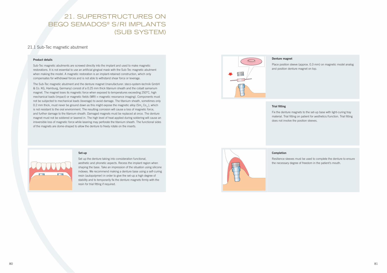
80 81
Product details
Sub-Tec magnetic abutments are screwed directly into the implant and used to make magnetic
restorations. It is not essential to use an artifi cial gingival mask with the Sub-Tec magnetic abutment
when making the model. A magnetic restoration is an implant-retained construction, which only
compensates for withdrawal forces and is not able to withstand shear force or leverage.
The Sub-Tec magnetic abutment and the denture magnet (manufacturer: steco-system-technik GmbH
& Co. KG, Hamburg, Germany) consist of a 0.25 mm thick titanium sheath and the cobalt samarium
magnet. The magnet loses its magnetic force when exposed to temperatures exceeding 250°C, high
mechanical loads (impact) or magnetic fi elds (MRI = magnetic resonance imaging). Components must
not be subjected to mechanical loads (leverage) to avoid damage. The titanium sheath, sometimes only
0.2 mm thick, must never be ground down as this might expose the magnetic alloy (Sm2 Co
17), which
is not resistant to the oral environment. The resulting corrosion will cause a loss of magnetic force,
and further damage to the titanium sheath. Damaged magnets must be replaced at once. The denture
magnet must not be soldered or lasered in. The high level of heat applied during soldering will cause an
irreversible loss of magnetic force while lasering may perforate the titanium sheath. The functional sides
of the magnets are dome-shaped to allow the denture to freely rotate on the inserts.
Set-up
Set up the denture taking into consideration functional,
aesthetic and phonetic aspects. Recess the implant region when
shaping the base. Take an impression of the situation using silicone
indexes. We recommend making a denture base using a self-curing
resin (autopolymer) in order to give the set-up a high degree of
stability and to temporarily fi x the denture magnets fi rmly with the
resin for trial fi tting if required.
21.1 Sub-Tec magnetic abutment
Trial fi tting
Fix the denture magnets to the set-up base with light-curing tray
material. Trial fi tting on patient for aesthetics / function. Trial fi tting
does not involve the position sleeves.
Denture magnet
Place position sleeve (approx. 0.3 mm) on magnetic model analog
and position denture magnet on top.
Completion
Resilience sleeves must be used to complete the denture to ensure
the necessary degree of freedom in the patient’s mouth.
21. SUPERSTRUCTURES ON BEGO SEMADOS® S / RI IMPLANTS
(SUB SYSTEM)
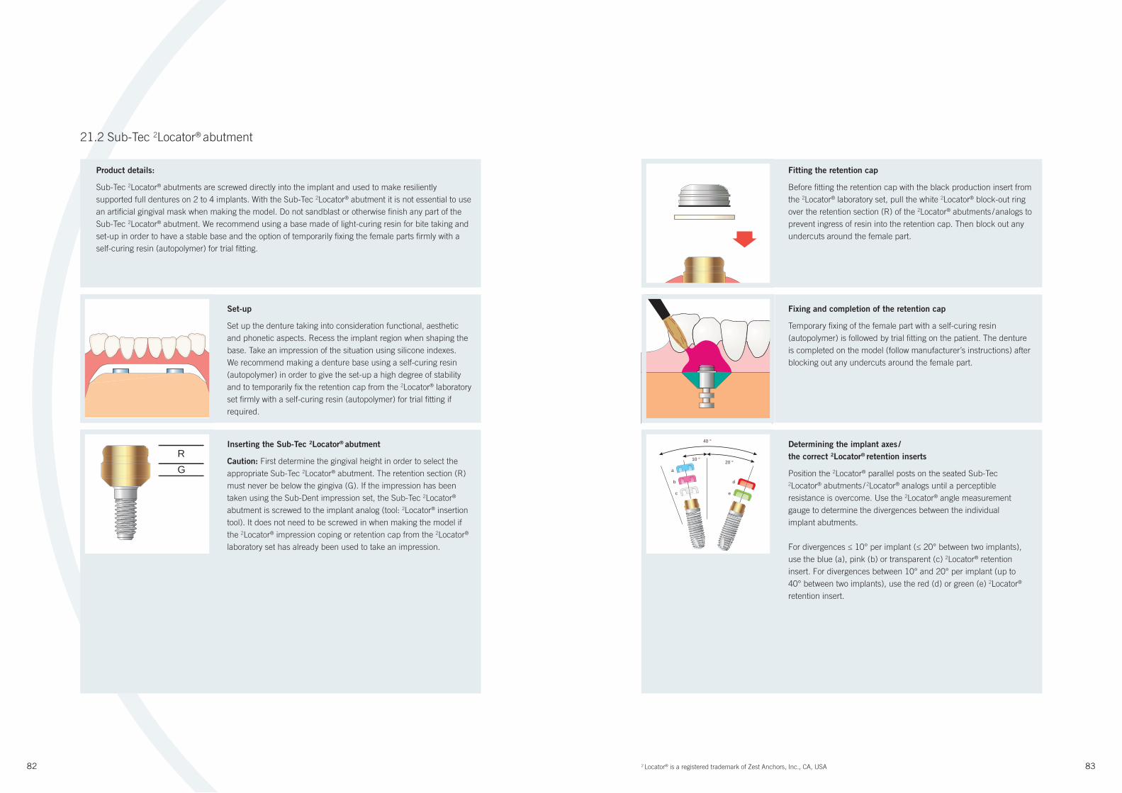
82 83
Product details:
Sub-Tec 2Locator® abutments are screwed directly into the implant and used to make resiliently
supported full dentures on 2 to 4 implants. With the Sub-Tec 2Locator® abutment it is not essential to use
an artifi cial gingival mask when making the model. Do not sandblast or otherwise fi nish any part of the
Sub-Tec 2Locator® abutment. We recommend using a base made of light-curing resin for bite taking and
set-up in order to have a stable base and the option of temporarily fi xing the female parts fi rmly with a
self-curing resin (autopolymer) for trial fi tting.
Set-up
Set up the denture taking into consideration functional, aesthetic
and phonetic aspects. Recess the implant region when shaping the
base. Take an impression of the situation using silicone indexes.
We recommend making a denture base using a self-curing resin
(autopolymer) in order to give the set-up a high degree of stability
and to temporarily fi x the retention cap from the 2Locator® laboratory
set fi rmly with a self-curing resin (autopolymer) for trial fi tting if
required.
21.2 Sub-Tec 2Locator® abutment
Fixing and completion of the retention cap
Temporary fi xing of the female part with a self-curing resin
(autopolymer) is followed by trial fi tting on the patient. The denture
is completed on the model (follow manufacturer’s instructions) after
blocking out any undercuts around the female part.
Fitting the retention cap
Before fi tting the retention cap with the black production insert from
the 2Locator® laboratory set, pull the white 2Locator® block-out ring
over the retention section (R) of the 2Locator® abutments / analogs to
prevent ingress of resin into the retention cap. Then block out any
undercuts around the female part.
40 °
10 °
a
b d
c e
20 °
Determining the implant axes /
the correct 2Locator® retention inserts
Position the 2Locator® parallel posts on the seated Sub-Tec 2Locator® abutments / 2Locator® analogs until a perceptible
resistance is overcome. Use the 2Locator® angle measurement
gauge to determine the divergences between the individual
implant abutments.
For divergences ≤ 10° per implant (≤ 20° between two implants),
use the blue (a), pink (b) or transparent (c) 2Locator® retention
insert. For divergences between 10° and 20° per implant (up to
40° between two implants), use the red (d) or green (e) 2Locator®
retention insert.
RG
Inserting the Sub-Tec 2Locator® abutment
Caution: First determine the gingival height in order to select the
appropriate Sub-Tec 2Locator® abutment. The retention section (R)
must never be below the gingiva (G). If the impression has been
taken using the Sub-Dent impression set, the Sub-Tec 2Locator®
abutment is screwed to the implant analog (tool: 2Locator® insertion
tool). It does not need to be screwed in when making the model if
the 2Locator® impression coping or retention cap from the 2Locator®
laboratory set has already been used to take an impression.
2 Locator® is a registered trademark of Zest Anchors, Inc., CA, USA
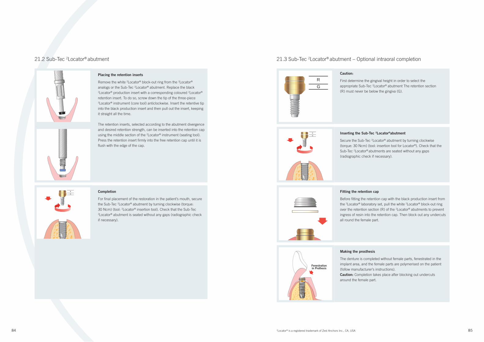
84 85
Placing the retention inserts
Remove the white 2Locator® block-out ring from the 2Locator®
analogs or the Sub-Tec 2Locator® abutment. Replace the black 2Locator® production insert with a corresponding coloured 2Locator®
retention insert. To do so, screw down the tip of the three-piece 2Locator® instrument (core tool) anticlockwise. Insert the retentive tip
into the black production insert and then pull out the insert, keeping
it straight all the time.
The retention inserts, selected according to the abutment divergence
and desired retention strength, can be inserted into the retention cap
using the middle section of the 2Locator® instrument (seating tool).
Press the retention insert fi rmly into the free retention cap until it is
fl ush with the edge of the cap.
Inserting the Sub-Tec 2Locator®abutment
Secure the Sub-Tec 2Locator® abutment by turning clockwise
(torque: 30 Ncm) (tool: insertion tool for Locator®). Check that the
Sub-Tec 2Locator® abutments are seated without any gaps
(radiographic check if necessary).
RG
Caution:
First determine the gingival height in order to select the
appropriate Sub-Tec 2Locator® abutment The retention section
(R) must never be below the gingiva (G).
Fitting the retention cap
Before fi tting the retention cap with the black production insert from
the 2Locator® laboratory set, pull the white 2Locator® block-out ring
over the retention section (R) of the 2Locator® abutments to prevent
ingress of resin into the retention cap. Then block out any undercuts
all round the female part.
Making the prosthesis
The denture is completed without female parts, fenestrated in the
implant area, and the female parts are polymerised on the patient
(follow manufacturer’s instructions).
Caution: Completion takes place after blocking out undercuts
around the female part.
Completion
For fi nal placement of the restoration in the patient’s mouth, secure
the Sub-Tec 2Locator® abutment by turning clockwise (torque:
30 Ncm) (tool: 2Locator® insertion tool). Check that the Sub-Tec 2Locator® abutment is seated without any gaps (radiographic check
if necessary).
RG
21.2 Sub-Tec 2Locator® abutment 21.3 Sub-Tec 2Locator® abutment – Optional intraoral completion
RG
2Locator® is a registered trademark of Zest Anchors Inc., CA, USA
Fenestrationin Prothesis

86 87
Determining the implant axes /
the correct Locator® retention inserts
Position the 2Locator® parallel posts on the seated Sub-Tec 2Locator®
abutments until a perceptible resistance is overcome. Use the 2Locator® angle measurement gauge to determine the divergences
between the individual implant abutments. For divergences ≤ 10°
per implant (≤ 20° between two implants), use the blue (a), pink
(b) or transparent (c) 2Locator® retention insert. For divergences
between 10° and 20° per implant (up to 40° between two implants),
use the red (d) or green (e) 2Locator® retention insert.
40 °
10 °
a
b d
c e
20 °
21.4 BeCe Sub-Tec ceramic abutment
Set-up
Make a set-up with acrylic teeth according to functional, phonetic
and aesthetic aspects. Take an impression of the situation using
silicone indexes.
Product details
BeCe Sub-Tec ceramic abutment for making cement-retained restorations.
Caution: The direct bonding of ceramics is not possible. Never use ceramic abutments in the molar
area or for terminal implants in the pre-molar area. A model with an artifi cial gingival mask is required
when using the abutment. The ceramic abutment can be individually shortened / ground with a diamond
ceramic shaper (e.g. BeCe Air Zirkon, BEGO) if continuous water cooling is used. A minimum material
thickness of 0.4 mm must be preserved. BeCe Sub-Tec ceramic abutments must not be sterilised using
an autoclave procedure (high-pressure steam sterilisation) or gamma / beta radiation. Avoid thermal
shock conditions such as switching suddenly from hot to cold and steam cleaning.
Inserting the ceramic abutment
Screw the BeCe Sub-Tec ceramic abutment onto the implant analog
with the Sub-TecPlus technician screw (slotted screw) (tool: slot
screwdriver).
2–3
Shortening the ceramic abutment
Use the silicone indices prepared in the set-up for shortening the
abutment (approx. 2 – 3 mm below the occlusal level).
Placing the retention inserts
Remove the white 2Locator® block-out ring from the 2Locator® analogs
or the Sub-Tec 2Locator® abutment. Replace the black 2Locator®
production insert with a corresponding coloured 2Locator® retention
insert. To do so, screw down the tip of the three-piece 2Locator®
instrument (core tool) anticlockwise. Insert the retentive tip into the
black production insert and then pull out the insert, keeping it
straight all the time.
The retention inserts, selected according to the abutment divergence
and desired retention strength, can be inserted into the retention cap
using the middle section of the 2Locator® instrument (seating tool).
Press the retention insert fi rmly into the free retention cap until it is
fl ush with the edge of the cap.
21.3 Sub-Tec 2Locator® abutment – Optional intraoral completion
2Locator® is a registered trademark of Zest Anchors Inc., CA, USA
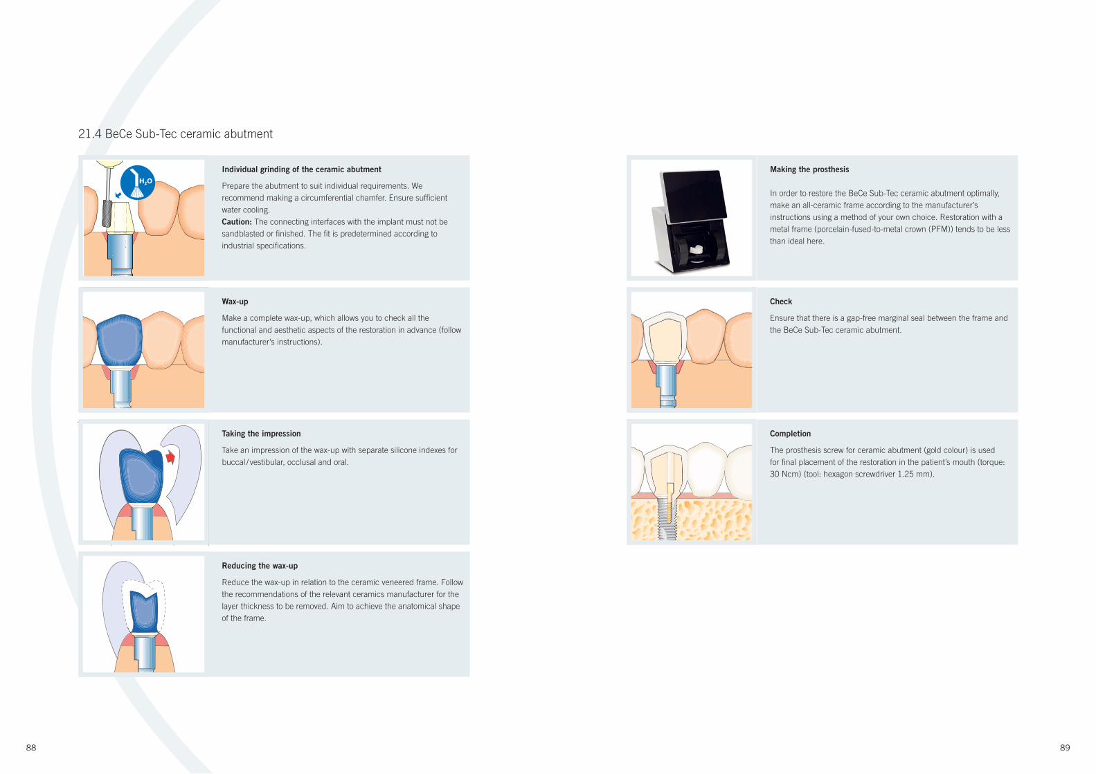
88 89
Individual grinding of the ceramic abutment
Prepare the abutment to suit individual requirements. We
recommend making a circumferential chamfer. Ensure suffi cient
water cooling.
Caution: The connecting interfaces with the implant must not be
sandblasted or fi nished. The fi t is predetermined according to
industrial specifi cations.
Making the prosthesis
In order to restore the BeCe Sub-Tec ceramic abutment optimally,
make an all-ceramic frame according to the manufacturer’s
instructions using a method of your own choice. Restoration with a
metal frame (porcelain-fused-to-metal crown (PFM)) tends to be less
than ideal here.
H2O
Wax-up
Make a complete wax-up, which allows you to check all the
functional and aesthetic aspects of the restoration in advance (follow
manufacturer’s instructions).
Taking the impression
Take an impression of the wax-up with separate silicone indexes for
buccal / vestibular, occlusal and oral.
Reducing the wax-up
Reduce the wax-up in relation to the ceramic veneered frame. Follow
the recommendations of the relevant ceramics manufacturer for the
layer thickness to be removed. Aim to achieve the anatomical shape
of the frame.
Check
Ensure that there is a gap-free marginal seal between the frame and
the BeCe Sub-Tec ceramic abutment.
Completion
The prosthesis screw for ceramic abutment (gold colour) is used
for fi nal placement of the restoration in the patient’s mouth (torque:
30 Ncm) (tool: hexagon screwdriver 1.25 mm).
21.4 BeCe Sub-Tec ceramic abutment
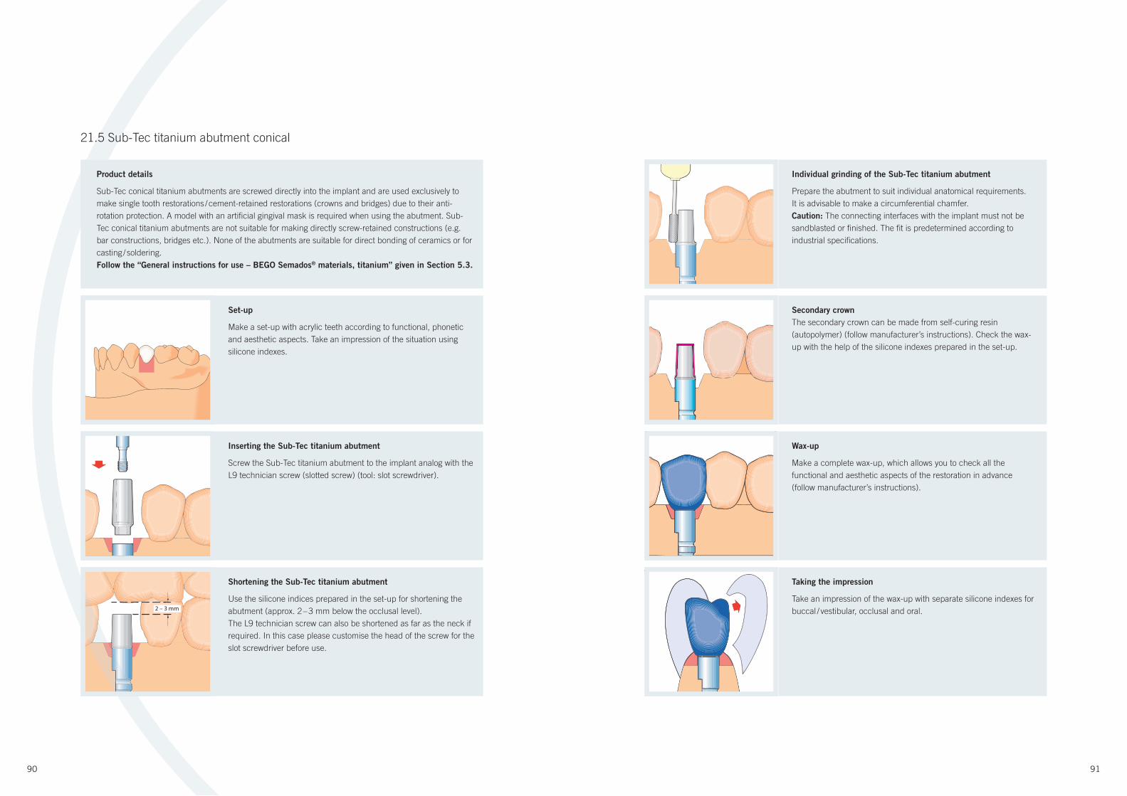
90 91
2 – 3 mm
21.5 Sub-Tec titanium abutment conical
Set-up
Make a set-up with acrylic teeth according to functional, phonetic
and aesthetic aspects. Take an impression of the situation using
silicone indexes.
Inserting the Sub-Tec titanium abutment
Screw the Sub-Tec titanium abutment to the implant analog with the
L9 technician screw (slotted screw) (tool: slot screwdriver).
Shortening the Sub-Tec titanium abutment
Use the silicone indices prepared in the set-up for shortening the
abutment (approx. 2 – 3 mm below the occlusal level).
The L9 technician screw can also be shortened as far as the neck if
required. In this case please customise the head of the screw for the
slot screwdriver before use.
Individual grinding of the Sub-Tec titanium abutment
Prepare the abutment to suit individual anatomical requirements.
It is advisable to make a circumferential chamfer.
Caution: The connecting interfaces with the implant must not be
sandblasted or fi nished. The fi t is predetermined according to
industrial specifi cations.
Secondary crown
The secondary crown can be made from self-curing resin
(autopolymer) (follow manufacturer’s instructions). Check the wax-
up with the help of the silicone indexes prepared in the set-up.
Wax-up
Make a complete wax-up, which allows you to check all the
functional and aesthetic aspects of the restoration in advance
(follow manufacturer’s instructions).
Product details
Sub-Tec conical titanium abutments are screwed directly into the implant and are used exclusively to
make single tooth restorations / cement-retained restorations (crowns and bridges) due to their anti-
rotation protection. A model with an artifi cial gingival mask is required when using the abutment. Sub-
Tec conical titanium abutments are not suitable for making directly screw-retained constructions (e.g.
bar constructions, bridges etc.). None of the abutments are suitable for direct bonding of ceramics or for
casting / soldering.
Follow the “General instructions for use – BEGO Semados® materials, titanium” given in Section 5.3.
Taking the impression
Take an impression of the wax-up with separate silicone indexes for
buccal / vestibular, occlusal and oral.
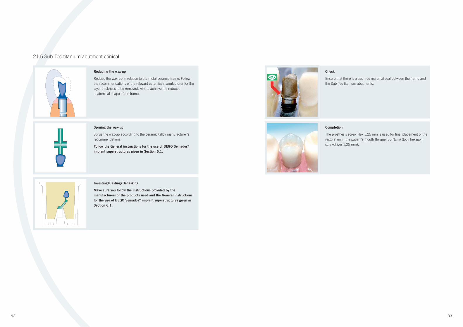
92 93
Check
Ensure that there is a gap-free marginal seal between the frame and
the Sub-Tec titanium abutments.
Reducing the wax-up
Reduce the wax-up in relation to the metal ceramic frame. Follow
the recommendations of the relevant ceramics manufacturer for the
layer thickness to be removed. Aim to achieve the reduced
anatomical shape of the frame.
Spruing the wax-up
Sprue the wax-up according to the ceramic / alloy manufacturer’s
recommendations.
Follow the General instructions for the use of BEGO Semados®
implant superstructures given in Section 6.1.
Investing / Casting / Defl asking
Make sure you follow the instructions provided by the
manufacturers of the products used and the General instructions
for the use of BEGO Semados® implant superstructures given in
Section 6.1.
Completion
The prosthesis screw Hex 1.25 mm is used for fi nal placement of the
restoration in the patient’s mouth (torque: 30 Ncm) (tool: hexagon
screwdriver 1.25 mm).
21.5 Sub-Tec titanium abutment conical
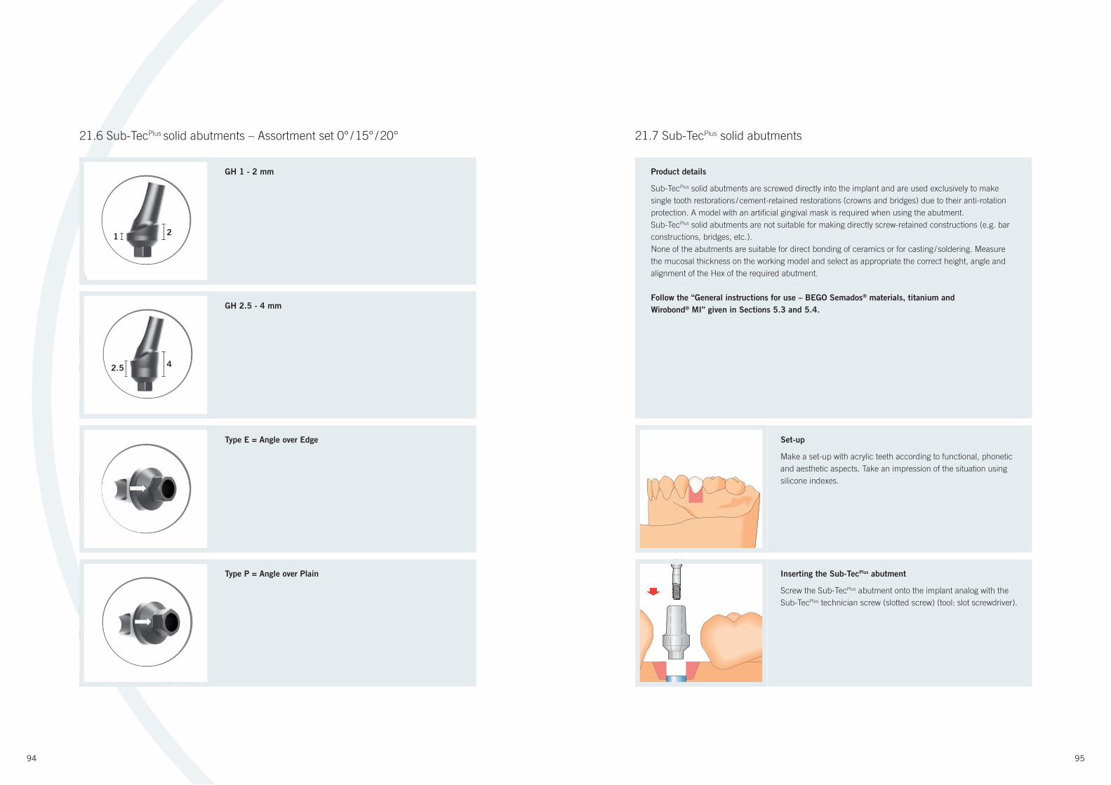
94 95
21.7 Sub-TecPlus solid abutments
Set-up
Make a set-up with acrylic teeth according to functional, phonetic
and aesthetic aspects. Take an impression of the situation using
silicone indexes.
GH 2.5 - 4 mm
Inserting the Sub-TecPlus abutment
Screw the Sub-TecPlus abutment onto the implant analog with the
Sub-TecPlus technician screw (slotted screw) (tool: slot screwdriver).
Type E = Angle over Edge
Type P = Angle over Plain
Product details
Sub-TecPlus solid abutments are screwed directly into the implant and are used exclusively to make
single tooth restorations / cement-retained restorations (crowns and bridges) due to their anti-rotation
protection. A model with an artifi cial gingival mask is required when using the abutment.
Sub-TecPlus solid abutments are not suitable for making directly screw-retained constructions (e.g. bar
constructions, bridges, etc.).
None of the abutments are suitable for direct bonding of ceramics or for casting / soldering. Measure
the mucosal thickness on the working model and select as appropriate the correct height, angle and
alignment of the Hex of the required abutment.
Follow the “General instructions for use – BEGO Semados® materials, titanium and
Wirobond® MI” given in Sections 5.3 and 5.4.
GH 1 - 2 mm
21.6 Sub-TecPlus solid abutments – Assortment set 0° / 15° / 20°
GH 1-2 mm
GH 2,5-4 mm
Typ K =Abwinkelung auf Kante
TA
eTyp F =Abwinkelung auf Fläche
2
4
1
2.5
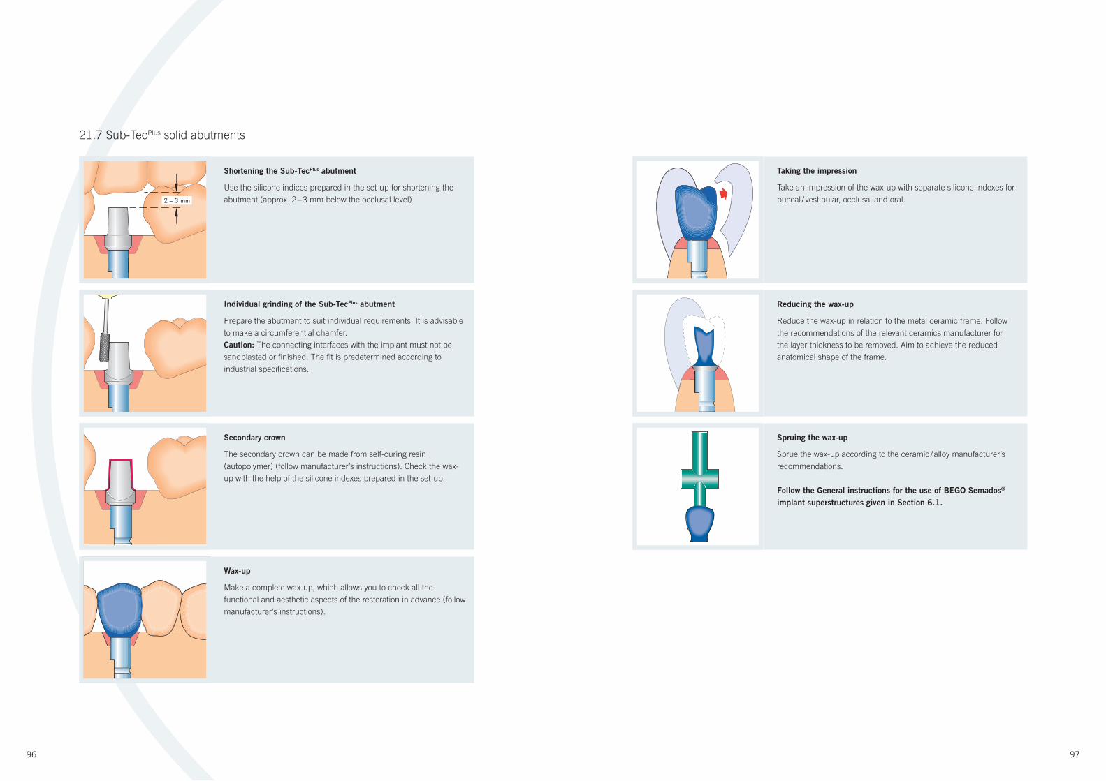
96 97
21.7 Sub-TecPlus solid abutments
Taking the impression
Take an impression of the wax-up with separate silicone indexes for
buccal / vestibular, occlusal and oral.
Individual grinding of the Sub-TecPlus abutment
Prepare the abutment to suit individual requirements. It is advisable
to make a circumferential chamfer.
Caution: The connecting interfaces with the implant must not be
sandblasted or fi nished. The fi t is predetermined according to
industrial specifi cations.
Secondary crown
The secondary crown can be made from self-curing resin
(autopolymer) (follow manufacturer’s instructions). Check the wax-
up with the help of the silicone indexes prepared in the set-up.
Wax-up
Make a complete wax-up, which allows you to check all the
functional and aesthetic aspects of the restoration in advance (follow
manufacturer’s instructions).
Reducing the wax-up
Reduce the wax-up in relation to the metal ceramic frame. Follow
the recommendations of the relevant ceramics manufacturer for
the layer thickness to be removed. Aim to achieve the reduced
anatomical shape of the frame.
Spruing the wax-up
Sprue the wax-up according to the ceramic / alloy manufacturer’s
recommendations.
Follow the General instructions for the use of BEGO Semados®
implant superstructures given in Section 6.1.
Shortening the Sub-TecPlus abutment
Use the silicone indices prepared in the set-up for shortening the
abutment (approx. 2 – 3 mm below the occlusal level).2 – 3 mm

98 99
21.7 Sub-TecPlus solid abutments 21.8 Sub-Tec Universal
Check
Ensure that there is a gap-free marginal seal between the frame and
the Sub-TecPlus abutments.
Completion
The Sub-TecPlus prosthesis screw is used for fi nal placement of the
restoration in the patient’s mouth (torque: 30 Ncm) (tool: hexagon
screwdriver 1.25 mm).
Set-up
Make a set-up with acrylic teeth according to functional, phonetic
and aesthetic aspects. Take an impression of the situation using
silicone indexes.
Inserting the Universal base Hex
Screw the Sub-Burnout acrylic sleeve and the Universal base Hex
onto the implant analog with the technician screw Universal (black)
(tool: slot screwdriver).
Product details
Sub-Tec Universal abutments are screwed directly into the implant and are used exclusively to make
single-tooth restorations with primary screw fi xation due to their anti-rotation protection. A model with
an artifi cial gingival mask is required when using the abutment. Sub-Tec Universal abutments are
not suitable for making directly screw-retained crown blocks, bridges or bar constructions. None of
the abutments are suitable for direct casting-on. Avoid applying excessive torque when screwing the
Sub-Burnout acrylic sleeve Universal in place prior to casting to prevent deformation of the material.
An attachment adhesive is required to complete the work (see Section 21.10). Adhesive bonding
merely serves to create a bacteria-proof seal for the connection between the Universal base Hex and
Sub-Burnout acrylic sleeve or the cast frame. The seat of the screw is in the Sub-Burnout acrylic
sleeve Universal or, later on, in the cast frame.
Investing / Casting / Defl asking
Make sure you follow the instructions provided by the
manufacturers of the products used and the General instructions
for the use of BEGO Semados® implant superstructures given in
Section 6.1.

100 101
21.8 Sub-Tec Universal
Shortening the Sub-Burnout acrylic sleeve Universal
Use the silicone indexes prepared in the set-up for shortening the
sleeve (approx. 2 mm below the occlusal level).
Spruing the wax-up
Sprue the wax-up according to the ceramic / alloy manufacturer’s
recommendations.
Follow the General instructions for the use of BEGO Semados®
implant superstructures given in Section 6.1.
Wax-up
Make a complete wax-up, which allows you to check all the
functional and aesthetic aspects of the restoration in advance (follow
manufacturer’s instructions).
Taking the impression
Take an impression of the wax-up with separate silicone indexes for
buccal / vestibular, occlusal and oral.
Reducing the wax-up
Reduce the wax-up in relation to the metal ceramic frame. Follow
the recommendations of the relevant ceramics manufacturer for the
layer thickness to be removed. Aim to achieve the reduced
anatomical shape of the frame.
Investing / Casting / Defl asking
Caution: Before investing, the Universal base Hex must be removed
from the wax-up. Make sure you take follow the instructions
provided by the manufacturers of the products used and the
General instructions for the use of BEGO Semados® implant
superstructures given in Section 6.1. The investment material is
removed with the help of a deinvesting drill, so as not to destroy
the internal fi t (screw support), and a precision sandblaster.
Precision-fi nishing the inner frame structures / screw support
The screw channel and screw support are precision-fi nished with
the internal reamer for Sub-Tec Universal (Art. no.: 55536).
Introduce the tool into the frame from the occlusal direction. Use
and then remove again in a clockwise direction without applying
pressure. It may be necessary to repeat this step before fi nal
cementing (e.g. if any ceramic material is left in the screw channel
on completion).
Caution: Never rotate the reamer anticlockwise.
Precision-fi nishing the bonded joint level
The basal surface of the cast frame in contact with the titanium
abutment is precision-fi nished with the external reamer for Sub-Tec
Universal (Art. no. 55537 or 55538). Make sure that the reamer is
used and removed again perpendicularly in a clockwise direction
without applying pressure. It may be necessary to repeat this step
before fi nal cementing (e.g. if any ceramic material is left in the basal
contact surface on completion).
Caution: Never rotate the reamer anticlockwise.
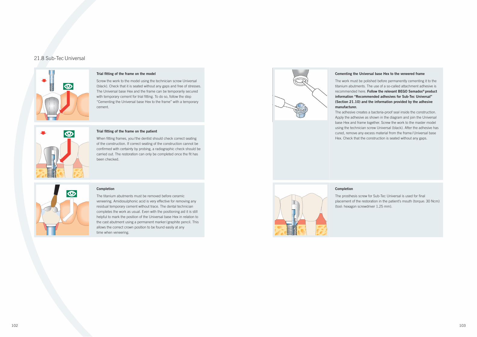
102 103
Trial fi tting of the frame on the model
Screw the work to the model using the technician screw Universal
(black). Check that it is seated without any gaps and free of stresses.
The Universal base Hex and the frame can be temporarily secured
with temporary cement for trial fi tting. To do so, follow the step
“Cementing the Universal base Hex to the frame” with a temporary
cement.
Cementing the Universal base Hex to the veneered frame
The work must be polished before permanently cementing it to the
titanium abutments. The use of a so-called attachment adhesive is
recommended here. Follow the relevant BEGO Semados® product
information “Recommended adhesives for Sub-Tec Universal”
(Section 21.10) and the information provided by the adhesive
manufacturer.
The adhesive creates a bacteria-proof seal inside the construction.
Apply the adhesive as shown in the diagram and join the Universal
base Hex and frame together. Screw the work to the master model
using the technician screw Universal (black). After the adhesive has
cured, remove any excess material from the frame / Universal base
Hex. Check that the construction is seated without any gaps.
Trial fi tting of the frame on the patient
When fi tting frames, you / the dentist should check correct seating
of the construction. If correct seating of the construction cannot be
confi rmed with certainty by probing, a radiographic check should be
carried out. The restoration can only be completed once the fi t has
been checked.
Completion
The titanium abutments must be removed before ceramic
veneering. Amidosulphonic acid is very effective for removing any
residual temporary cement without trace. The dental technician
completes the work as usual. Even with the positioning aid it is still
helpful to mark the position of the Universal base Hex in relation to
the cast abutment using a permanent marker / graphite pencil. This
allows the correct crown position to be found easily at any
time when veneering.
Completion
The prosthesis screw for Sub-Tec Universal is used for fi nal
placement of the restoration in the patient’s mouth (torque: 30 Ncm)
(tool: hexagon screwdriver 1.25 mm).
21.8 Sub-Tec Universal
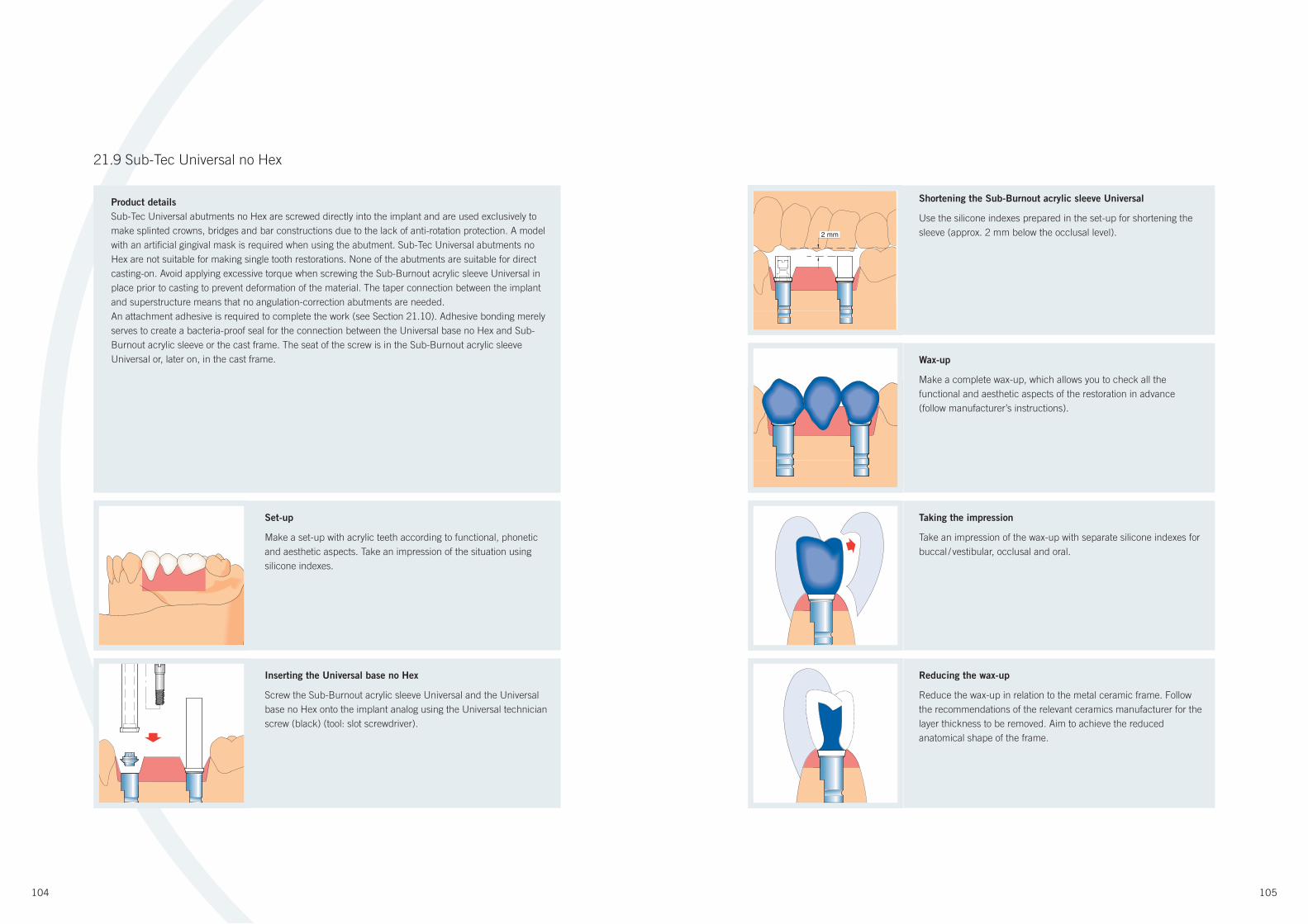
104 105
Product details
Sub-Tec Universal abutments no Hex are screwed directly into the implant and are used exclusively to
make splinted crowns, bridges and bar constructions due to the lack of anti-rotation protection. A model
with an artifi cial gingival mask is required when using the abutment. Sub-Tec Universal abutments no
Hex are not suitable for making single tooth restorations. None of the abutments are suitable for direct
casting-on. Avoid applying excessive torque when screwing the Sub-Burnout acrylic sleeve Universal in
place prior to casting to prevent deformation of the material. The taper connection between the implant
and superstructure means that no angulation-correction abutments are needed.
An attachment adhesive is required to complete the work (see Section 21.10). Adhesive bonding merely
serves to create a bacteria-proof seal for the connection between the Universal base no Hex and Sub-
Burnout acrylic sleeve or the cast frame. The seat of the screw is in the Sub-Burnout acrylic sleeve
Universal or, later on, in the cast frame.
Set-up
Make a set-up with acrylic teeth according to functional, phonetic
and aesthetic aspects. Take an impression of the situation using
silicone indexes.
21.9 Sub-Tec Universal no Hex
Wax-up
Make a complete wax-up, which allows you to check all the
functional and aesthetic aspects of the restoration in advance
(follow manufacturer’s instructions).
Shortening the Sub-Burnout acrylic sleeve Universal
Use the silicone indexes prepared in the set-up for shortening the
sleeve (approx. 2 mm below the occlusal level).
Taking the impression
Take an impression of the wax-up with separate silicone indexes for
buccal / vestibular, occlusal and oral.
Inserting the Universal base no Hex
Screw the Sub-Burnout acrylic sleeve Universal and the Universal
base no Hex onto the implant analog using the Universal technician
screw (black) (tool: slot screwdriver).
Reducing the wax-up
Reduce the wax-up in relation to the metal ceramic frame. Follow
the recommendations of the relevant ceramics manufacturer for the
layer thickness to be removed. Aim to achieve the reduced
anatomical shape of the frame.
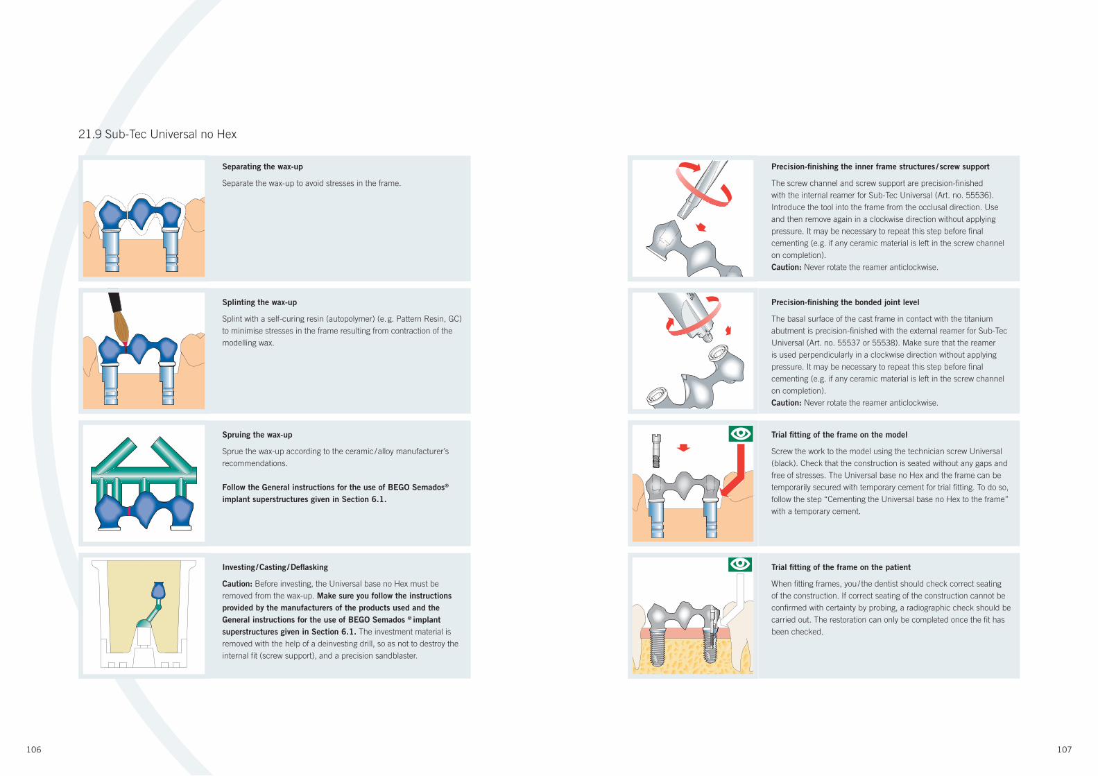
106 107
Spruing the wax-up
Sprue the wax-up according to the ceramic / alloy manufacturer’s
recommendations.
Follow the General instructions for the use of BEGO Semados®
implant superstructures given in Section 6.1.
21.9 Sub-Tec Universal no Hex
Trial fi tting of the frame on the model
Screw the work to the model using the technician screw Universal
(black). Check that the construction is seated without any gaps and
free of stresses. The Universal base no Hex and the frame can be
temporarily secured with temporary cement for trial fi tting. To do so,
follow the step “Cementing the Universal base no Hex to the frame”
with a temporary cement.
Precision-fi nishing the bonded joint level
The basal surface of the cast frame in contact with the titanium
abutment is precision-fi nished with the external reamer for Sub-Tec
Universal (Art. no. 55537 or 55538). Make sure that the reamer
is used perpendicularly in a clockwise direction without applying
pressure. It may be necessary to repeat this step before fi nal
cementing (e.g. if any ceramic material is left in the screw channel
on completion).
Caution: Never rotate the reamer anticlockwise.
Precision-fi nishing the inner frame structures / screw support
The screw channel and screw support are precision-fi nished
with the internal reamer for Sub-Tec Universal (Art. no. 55536).
Introduce the tool into the frame from the occlusal direction. Use
and then remove again in a clockwise direction without applying
pressure. It may be necessary to repeat this step before fi nal
cementing (e.g. if any ceramic material is left in the screw channel
on completion).
Caution: Never rotate the reamer anticlockwise.
Splinting the wax-up
Splint with a self-curing resin (autopolymer) (e. g. Pattern Resin, GC)
to minimise stresses in the frame resulting from contraction of the
modelling wax.
Separating the wax-up
Separate the wax-up to avoid stresses in the frame.
Investing / Casting / Defl asking
Caution: Before investing, the Universal base no Hex must be
removed from the wax-up. Make sure you follow the instructions
provided by the manufacturers of the products used and the
General instructions for the use of BEGO Semados ® implant
superstructures given in Section 6.1. The investment material is
removed with the help of a deinvesting drill, so as not to destroy the
internal fi t (screw support), and a precision sandblaster.
Trial fi tting of the frame on the patient
When fi tting frames, you / the dentist should check correct seating
of the construction. If correct seating of the construction cannot be
confi rmed with certainty by probing, a radiographic check should be
carried out. The restoration can only be completed once the fi t has
been checked.
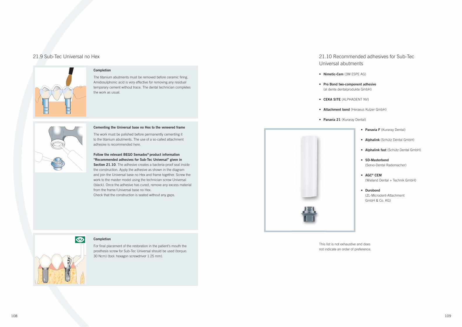
108 109
Completion
Make a set-up with acrylic teeth according to functional, phonetic
and aesthetic aspects. Take an impression of the situation using
silicone indexes.
21.9 Sub-Tec Universal no Hex
Cementing the Universal base no Hex to the veneered frame
The work must be polished before permanently cementing it
to the titanium abutments. The use of a so-called attachment
adhesive is recommended here.
Follow the relevant BEGO Semados® product information
“Recommended adhesives for Sub-Tec Universal” given in
Section 21.10. The adhesive creates a bacteria-proof seal inside
the construction. Apply the adhesive as shown in the diagram
and join the Universal base no Hex and frame together. Screw the
work to the master model using the technician screw Universal
(black). Once the adhesive has cured, remove any excess material
from the frame / Universal base no Hex.
Check that the construction is seated without any gaps.
Completion
The titanium abutments must be removed before ceramic fi ring.
Amidosulphonic acid is very effective for removing any residual
temporary cement without trace. The dental technician completes
the work as usual.
Completion
For fi nal placement of the restoration in the patient’s mouth the
prosthesis screw for Sub-Tec Universal should be used (torque:
30 Ncm) (tool: hexagon screwdriver 1.25 mm).
21.10 Recommended adhesives for Sub-Tec
Universal abutments
• Nimetic-Cem (3M ESPE AG)
• Pro Bond two-component adhesive
(al dente dentalprodukte GmbH)
• CEKA SITE (ALPHADENT NV)
• Attachment bond (Heraeus Kulzer GmbH)
• Panavia 21 (Kuraray Dental)
• Panavia F (Kuraray Dental)
• Alphalink (Schütz Dental GmbH)
• Alphalink fast (Schütz Dental GmbH)
• SD-Masterbond
(Servo-Dental Rademacher)
• AGC® CEM
(Wieland Dental + Technik GmbH)
• Durobond
(ZL-Microdent-Attachment
GmbH & Co. KG)
This list is not exhaustive and does
not indicate an order of preference.
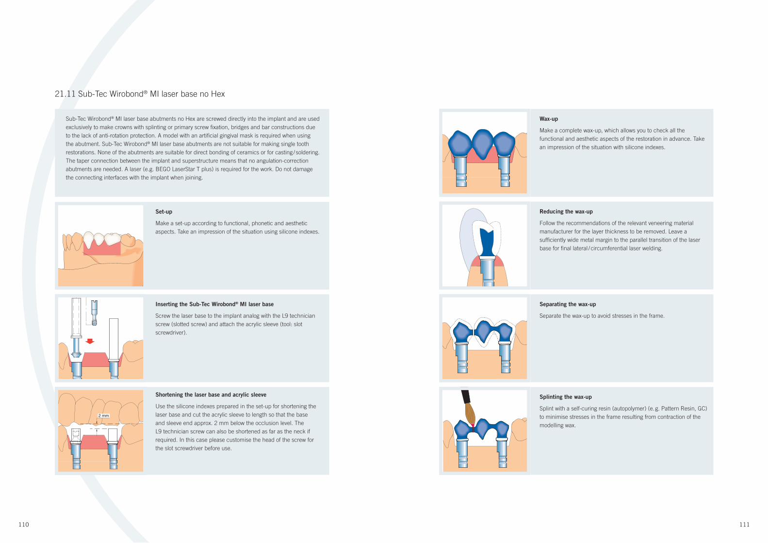
110 111
Sub-Tec Wirobond® MI laser base abutments no Hex are screwed directly into the implant and are used
exclusively to make crowns with splinting or primary screw fi xation, bridges and bar constructions due
to the lack of anti-rotation protection. A model with an artifi cial gingival mask is required when using
the abutment. Sub-Tec Wirobond® MI laser base abutments are not suitable for making single tooth
restorations. None of the abutments are suitable for direct bonding of ceramics or for casting / soldering.
The taper connection between the implant and superstructure means that no angulation-correction
abutments are needed. A laser (e.g. BEGO LaserStar T plus) is required for the work. Do not damage
the connecting interfaces with the implant when joining.
Set-up
Make a set-up according to functional, phonetic and aesthetic
aspects. Take an impression of the situation using silicone indexes.
21.11 Sub-Tec Wirobond® MI laser base no Hex
Reducing the wax-up
Follow the recommendations of the relevant veneering material
manufacturer for the layer thickness to be removed. Leave a
suffi ciently wide metal margin to the parallel transition of the laser
base for fi nal lateral / circumferential laser welding.
Wax-up
Make a complete wax-up, which allows you to check all the
functional and aesthetic aspects of the restoration in advance. Take
an impression of the situation with silicone indexes.
Separating the wax-up
Separate the wax-up to avoid stresses in the frame.
Shortening the laser base and acrylic sleeve
Use the silicone indexes prepared in the set-up for shortening the
laser base and cut the acrylic sleeve to length so that the base
and sleeve end approx. 2 mm below the occlusion level. The
L9 technician screw can also be shortened as far as the neck if
required. In this case please customise the head of the screw for
the slot screwdriver before use.
Inserting the Sub-Tec Wirobond® MI laser base
Screw the laser base to the implant analog with the L9 technician
screw (slotted screw) and attach the acrylic sleeve (tool: slot
screwdriver).
Splinting the wax-up
Splint with a self-curing resin (autopolymer) (e. g. Pattern Resin, GC)
to minimise stresses in the frame resulting from contraction of the
modelling wax.
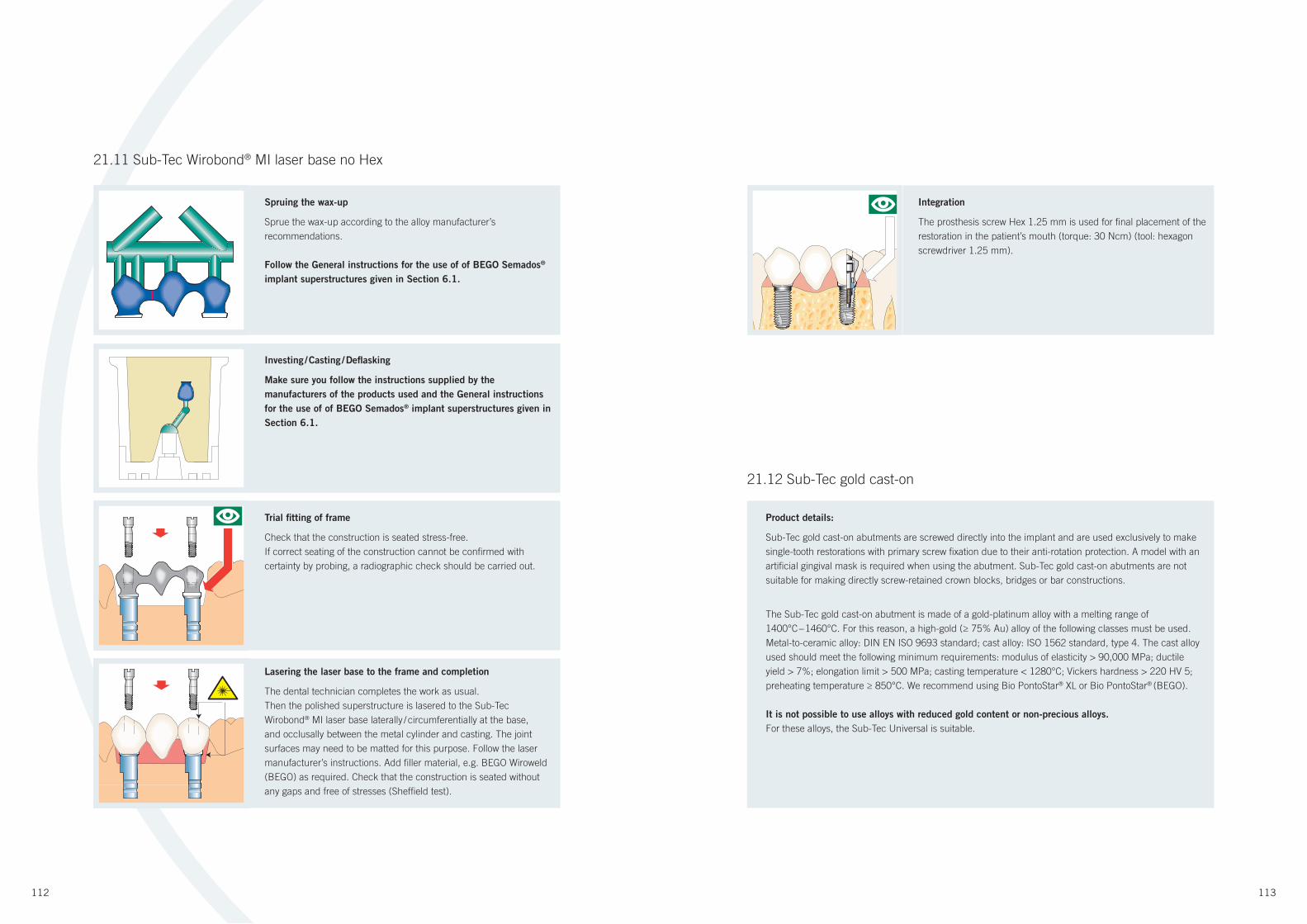
112 113
Investing / Casting / Defl asking
Make sure you follow the instructions supplied by the
manufacturers of the products used and the General instructions
for the use of of BEGO Semados® implant superstructures given in
Section 6.1.
Spruing the wax-up
Sprue the wax-up according to the alloy manufacturer’s
recommendations.
Follow the General instructions for the use of of BEGO Semados®
implant superstructures given in Section 6.1.
21.11 Sub-Tec Wirobond® MI laser base no Hex
Lasering the laser base to the frame and completion
The dental technician completes the work as usual.
Then the polished superstructure is lasered to the Sub-Tec
Wirobond® MI laser base laterally / circumferentially at the base,
and occlusally between the metal cylinder and casting. The joint
surfaces may need to be matted for this purpose. Follow the laser
manufacturer’s instructions. Add fi ller material, e.g. BEGO Wiroweld
(BEGO) as required. Check that the construction is seated without
any gaps and free of stresses (Sheffi eld test).
Integration
The prosthesis screw Hex 1.25 mm is used for fi nal placement of the
restoration in the patient’s mouth (torque: 30 Ncm) (tool: hexagon
screwdriver 1.25 mm).
Trial fi tting of frame
Check that the construction is seated stress-free.
If correct seating of the construction cannot be confi rmed with
certainty by probing, a radiographic check should be carried out.
Product details:
Sub-Tec gold cast-on abutments are screwed directly into the implant and are used exclusively to make
single-tooth restorations with primary screw fi xation due to their anti-rotation protection. A model with an
artifi cial gingival mask is required when using the abutment. Sub-Tec gold cast-on abutments are not
suitable for making directly screw-retained crown blocks, bridges or bar constructions.
The Sub-Tec gold cast-on abutment is made of a gold-platinum alloy with a melting range of
1400°C – 1460°C. For this reason, a high-gold (≥ 75% Au) alloy of the following classes must be used.
Metal-to-ceramic alloy: DIN EN ISO 9693 standard; cast alloy: ISO 1562 standard, type 4. The cast alloy
used should meet the following minimum requirements: modulus of elasticity > 90,000 MPa; ductile
yield > 7%; elongation limit > 500 MPa; casting temperature < 1280°C; Vickers hardness > 220 HV 5;
preheating temperature ≥ 850°C. We recommend using Bio PontoStar® XL or Bio PontoStar® (BEGO).
It is not possible to use alloys with reduced gold content or non-precious alloys.
For these alloys, the Sub-Tec Universal is suitable.
21.12 Sub-Tec gold cast-on

114 115
Reducing the wax-up
Reduce the wax-up in relation to the metal ceramic frame. Follow the
recommendations of the relevant ceramics manufacturer for the layer
thickness to be removed. Aim to achieve the reduced
anatomical shape of the frame.
Shortening the Sub-Burnout acrylic sleeve gold cast-on
Place the acrylic sleeve on the cast-on abutment. Close the gap
between the Sub cast-on abutment and the Sub-burnout acrylic
sleeve gold cast-on with wax. It has proven useful to secure the
components to each other with some cyanoacrylate adhesive. Use
the the silicone indexes prepared in the set-up for shortening the
sleeve (approx. 2 mm below the occlusal level). The L9 technician
screw can also be shortened as far as the neck if required. In this
case please customise the head of the screw for the slot screwdriver
before use.
Wax-up
Make a complete wax-up, which allows you to check all the
functional and aesthetic aspects of the restoration in advance
(follow manufacturer’s instructions).
Taking the impression
Take an impression of the wax-up with separate silicone indexes for
buccal / vestibular, occlusal and oral.
Inserting the Sub cast-on abutment
Screw the Sub-cast-on abutment to the implant analog with the L9
technician screw (tool: slot screwdriver).
Spruing the wax-up
Sprue the wax-up according to the ceramic / alloy manufacturer’s
recommendations. Weigh the wax-up carefully and calculate the alloy
requirement (minus 0.5 g for each cast-on abutment).
Follow the General instructions for the use of BEGO Semados®
implant superstructures given in Section 6.1.
21.12 Sub-Tec gold cast-on

116 117
Casting
When processing Semados® cast-on abutments, the preheating
temperature of 850°C must be attained to ensure cast-on
abutments which are fl awless in metallurgical terms. Lower
temperatures cause insuffi cient diffusion of the alloy constituents.
The connection is then highly susceptible to corrosion and
has little resistance to mechanical loads (casting temperature
< 1280°C).
Make sure you follow the instructions provided by the
manufacturers of the products used and the General instructions
for the use of BEGO Semados® implant superstructures given in
Section 6.1.
Defl asking
The investment material is removed with the help of a deinvesting
drill, so as not to destroy the internal fi t (screw support), and
a precision sandblaster. Optionally the investment material
can be removed with a suitable fl uid (e. g. hydrofl uoric acid) in
combination with ultrasound treatment. As high-melting alloys do
not bond with investment material, the cast-on abutments emerge
from the material with a high-gloss fi nish.
To ensure optimum fi t of the prosthesis screw, use the internal
reamer for Sub / Supra-Tec gold cast-on (Art. no.: 53735) (never
rotate reamer anticlockwise).
Caution: The connecting interfaces with the implant must not be
sandblasted or fi nished. The fi t is predetermined according to
industrial specifi cations.
To help remove all traces of investment material from the casting
by sandblasting with aluminium oxide, the exposed cast-on
abutments can be coated with cold-cured polymer to protect them.
The construction can then be carefully sandblasted once the resin
material has cured.
21.12 Sub-Tec gold cast-on
Investing
Before investing, remove wax shavings etc. from the cast-on
abutments. Do not use wetting agents, as they may form a fi lm on
the cast-on abutments, possibly resulting in defective casting. The
use of a phosphate-bonded investment material is recommended
here During preheating, castable alloys (cast-on abutments) put
considerable stress on the investment material due to their coeffi cient
of thermal expansion. If, during casting, constituents of the cast alloy
shoot over the implant abutments (“skin formation”), this points to
the investment material not being suffi ciently stable. In this case an
investment material of higher quality should be used.
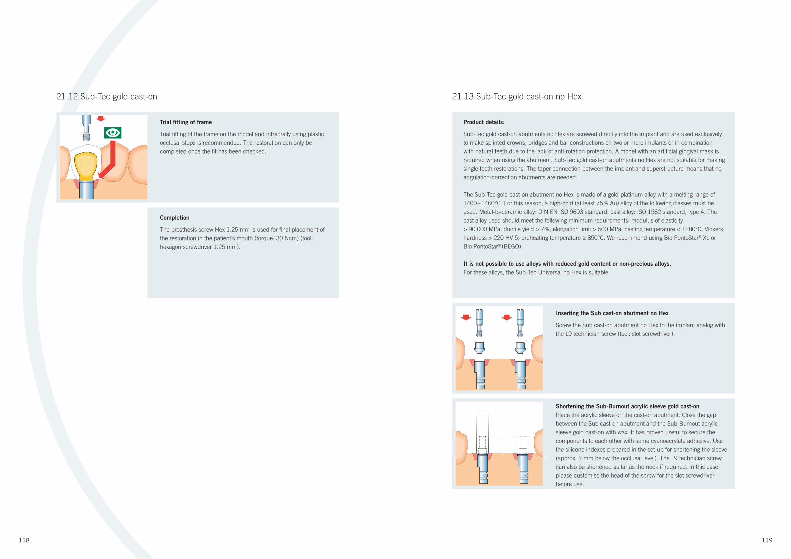
118 119
21.13 Sub-Tec gold cast-on no Hex
Inserting the Sub cast-on abutment no Hex
Screw the Sub cast-on abutment no Hex to the implant analog with
the L9 technician screw (tool: slot screwdriver).
Shortening the Sub-Burnout acrylic sleeve gold cast-on
Place the acrylic sleeve on the cast-on abutment. Close the gap
between the Sub cast-on abutment and the Sub-Burnout acrylic
sleeve gold cast-on with wax. It has proven useful to secure the
components to each other with some cyanoacrylate adhesive. Use
the silicone indexes prepared in the set-up for shortening the sleeve
(approx. 2 mm below the occlusal level). The L9 technician screw
can also be shortened as far as the neck if required. In this case
please customise the head of the screw for the slot screwdriver
before use.
Trial fi tting of frame
Trial fi tting of the frame on the model and intraorally using plastic
occlusal stops is recommended. The restoration can only be
completed once the fi t has been checked.
Completion
The prosthesis screw Hex 1.25 mm is used for fi nal placement of
the restoration in the patient’s mouth (torque: 30 Ncm) (tool:
hexagon screwdriver 1.25 mm).
Product details:
Sub-Tec gold cast-on abutments no Hex are screwed directly into the implant and are used exclusively
to make splinted crowns, bridges and bar constructions on two or more implants or in combination
with natural teeth due to the lack of anti-rotation protection. A model with an artifi cial gingival mask is
required when using the abutment. Sub-Tec gold cast-on abutments no Hex are not suitable for making
single tooth restorations. The taper connection between the implant and superstructure means that no
angulation-correction abutments are needed.
The Sub-Tec gold cast-on abutment no Hex is made of a gold-platinum alloy with a melting range of
1400 – 1460°C. For this reason, a high-gold (at least 75% Au) alloy of the following classes must be
used. Metal-to-ceramic alloy: DIN EN ISO 9693 standard; cast alloy: ISO 1562 standard, type 4. The
cast alloy used should meet the following minimum requirements: modulus of elasticity
> 90,000 MPa; ductile yield > 7%; elongation limit > 500 MPa; casting temperature < 1280°C; Vickers
hardness > 220 HV 5; preheating temperature ≥ 850°C. We recommend using Bio PontoStar® XL or
Bio PontoStar® (BEGO).
It is not possible to use alloys with reduced gold content or non-precious alloys.
For these alloys, the Sub-Tec Universal no Hex is suitable.
21.12 Sub-Tec gold cast-on

120 121
Taking the impression
Take an impression of the wax-up with separate silicone indexes for
buccal / vestibular, occlusal and oral.
Wax-up
Make a complete wax-up, which allows you to check all the
functional and aesthetic aspects of the restoration in advance (follow
manufacturer’s instructions).
21.13 Sub-Tec gold cast-on no Hex
Separating the wax-up
Separate the wax-up to avoid stresses in the frame.
Spruing the wax-up
Sprue the wax-up according to the ceramic / alloy manufacturer’s
recommendations.
Weigh the wax-up carefully and calculate the alloy requirement
(minus 0.5 g for each cast-on abutment).
Follow the General instructions for the use of BEGO Semados®
implant superstructures given in Section 6.1.
Splinting
Splint with a self-curing resin (autopolymer) (e.g. Pattern Resin, GC)
to minimise stresses in the frame resulting from contraction of the
modelling wax.
Reducing the wax-up
Follow the recommendations of the relevant ceramics manufacturer
for the layer thickness to be removed.
Aim to achieve the reduced anatomical shape of the frame.

122 123
21.13 Sub-Tec gold cast-on no Hex
Casting
When processing Semados® cast-on abutments, the preheating
temperature of 850°C must be attained to ensure cast-on
abutments which are fl awless in metallurgical terms. Lower
temperatures cause insuffi cient diffusion of the alloy constituents.
The connection is then highly susceptible to corrosion and has
little resistance to mechanical loads (casting temperature
< 1280°C).
Make sure you follow the instructions provided by the
manufacturers of the products used and the General instructions
for the use of BEGO Semados® implant superstructures given in
Section 6.1.
Defl asking
The investment material is removed with the help of a deinvesting
drill, so as not to destroy the internal fi t (screw support), and
a precision sandblaster. Optionally the investment material
can be removed with a suitable fl uid (e. g. hydrofl uoric acid) in
combination with ultrasound treatment. As high-melting alloys do
not bond with investment material, the cast-on abutments emerge
from the material with a high-gloss fi nish.
To obtain optimum fi t of the prosthesis screw, use the internal
reamer for Sub / Supra-Tec gold cast-on (Art. no.: 53735) (never
rotate reamer anticlockwise).
Caution: The connecting interfaces with the implant must not be
sandblasted or fi nished. The fi t is predetermined according to
industrial specifi cations.
To help remove all traces of investment material from the casting
by sandblasting with special corundum (aluminium oxide), the
exposed cast-on abutments can be coated with cold-cured
polymer to protect them. The construction can then be carefully
sandblasted once the resin material has cured.
Investing
Before investing, remove wax shavings etc. from the cast-on
abutments. Do not use wetting agents, as they may form a fi lm on
the cast-on abutments, possibly resulting in defective casting. A
phosphate-bonded investment material is recommended. During
preheating, castable alloys (cast-on abutments) put considerable
stress on the investment material due to their coeffi cient of thermal
expansion. If, during casting, constituents of the cast alloy shoot over
the implant abutments (“skin formation”), this points to the
investment material not being suffi ciently stable. In this case an
investment material of higher quality should be used.
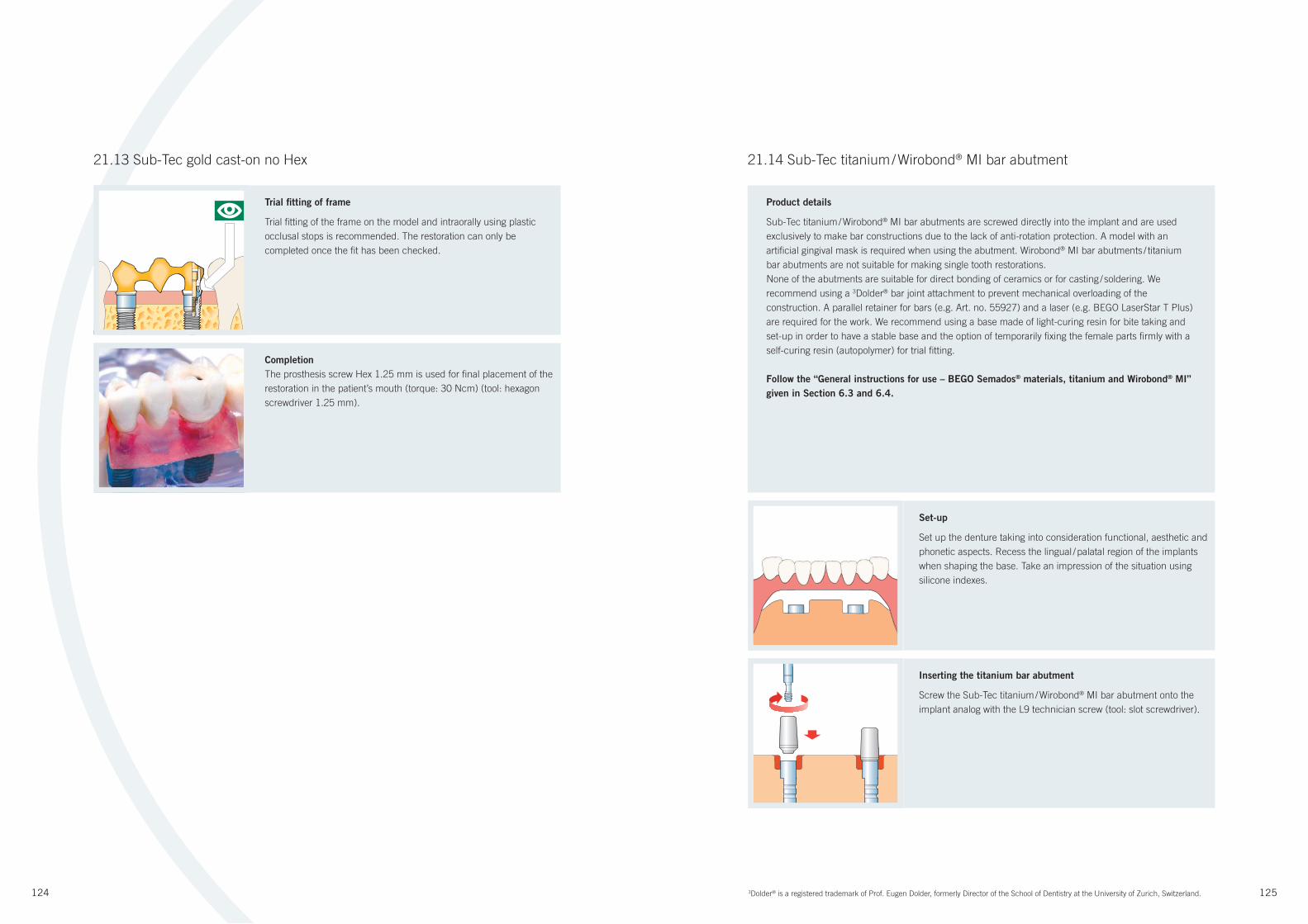
124 125
21.13 Sub-Tec gold cast-on no Hex
Trial fi tting of frame
Trial fi tting of the frame on the model and intraorally using plastic
occlusal stops is recommended. The restoration can only be
completed once the fi t has been checked.
Completion
The prosthesis screw Hex 1.25 mm is used for fi nal placement of the
restoration in the patient’s mouth (torque: 30 Ncm) (tool: hexagon
screwdriver 1.25 mm).
21.14 Sub-Tec titanium / Wirobond® MI bar abutment
Set-up
Set up the denture taking into consideration functional, aesthetic and
phonetic aspects. Recess the lingual / palatal region of the implants
when shaping the base. Take an impression of the situation using
silicone indexes.
Inserting the titanium bar abutment
Screw the Sub-Tec titanium / Wirobond® MI bar abutment onto the
implant analog with the L9 technician screw (tool: slot screwdriver).
Product details
Sub-Tec titanium / Wirobond® MI bar abutments are screwed directly into the implant and are used
exclusively to make bar constructions due to the lack of anti-rotation protection. A model with an
artifi cial gingival mask is required when using the abutment. Wirobond® MI bar abutments / titanium
bar abutments are not suitable for making single tooth restorations.
None of the abutments are suitable for direct bonding of ceramics or for casting / soldering. We
recommend using a 3Dolder® bar joint attachment to prevent mechanical overloading of the
construction. A parallel retainer for bars (e.g. Art. no. 55927) and a laser (e.g. BEGO LaserStar T Plus)
are required for the work. We recommend using a base made of light-curing resin for bite taking and
set-up in order to have a stable base and the option of temporarily fi xing the female parts fi rmly with a
self-curing resin (autopolymer) for trial fi tting.
Follow the “General instructions for use – BEGO Semados® materials, titanium and Wirobond® MI”
given in Section 6.3 and 6.4.
3Dolder® is a registered trademark of Prof. Eugen Dolder, formerly Director of the School of Dentistry at the University of Zurich, Switzerland.
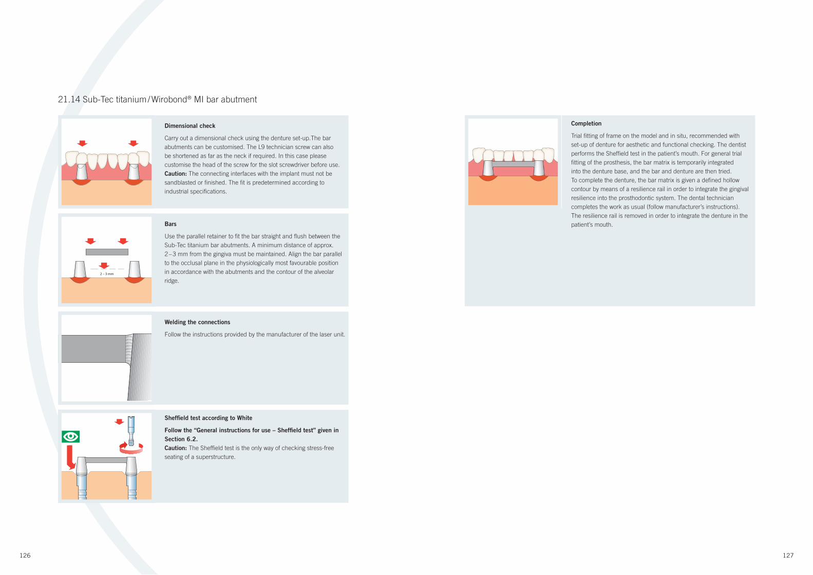
126 127
Bars
Use the parallel retainer to fi t the bar straight and fl ush between the
Sub-Tec titanium bar abutments. A minimum distance of approx.
2 – 3 mm from the gingiva must be maintained. Align the bar parallel
to the occlusal plane in the physiologically most favourable position
in accordance with the abutments and the contour of the alveolar
ridge.
2 – 3 mm
Sheffi eld test according to White
Follow the “General instructions for use – Sheffield test” given in
Section 6.2.
Caution: The Sheffi eld test is the only way of checking stress-free
seating of a superstructure.
Completion
Trial fi tting of frame on the model and in situ, recommended with
set-up of denture for aesthetic and functional checking. The dentist
performs the Sheffield test in the patient’s mouth. For general trial
fi tting of the prosthesis, the bar matrix is temporarily integrated
into the denture base, and the bar and denture are then tried.
To complete the denture, the bar matrix is given a defi ned hollow
contour by means of a resilience rail in order to integrate the gingival
resilience into the prosthodontic system. The dental technician
completes the work as usual (follow manufacturer’s instructions).
The resilience rail is removed in order to integrate the denture in the
patient’s mouth.
Welding the connections
Follow the instructions provided by the manufacturer of the laser unit.
21.14 Sub-Tec titanium / Wirobond® MI bar abutment
Dimensional check
Carry out a dimensional check using the denture set-up.The bar
abutments can be customised. The L9 technician screw can also
be shortened as far as the neck if required. In this case please
customise the head of the screw for the slot screwdriver before use.
Caution: The connecting interfaces with the implant must not be
sandblasted or fi nished. The fi t is predetermined according to
industrial specifi cations.
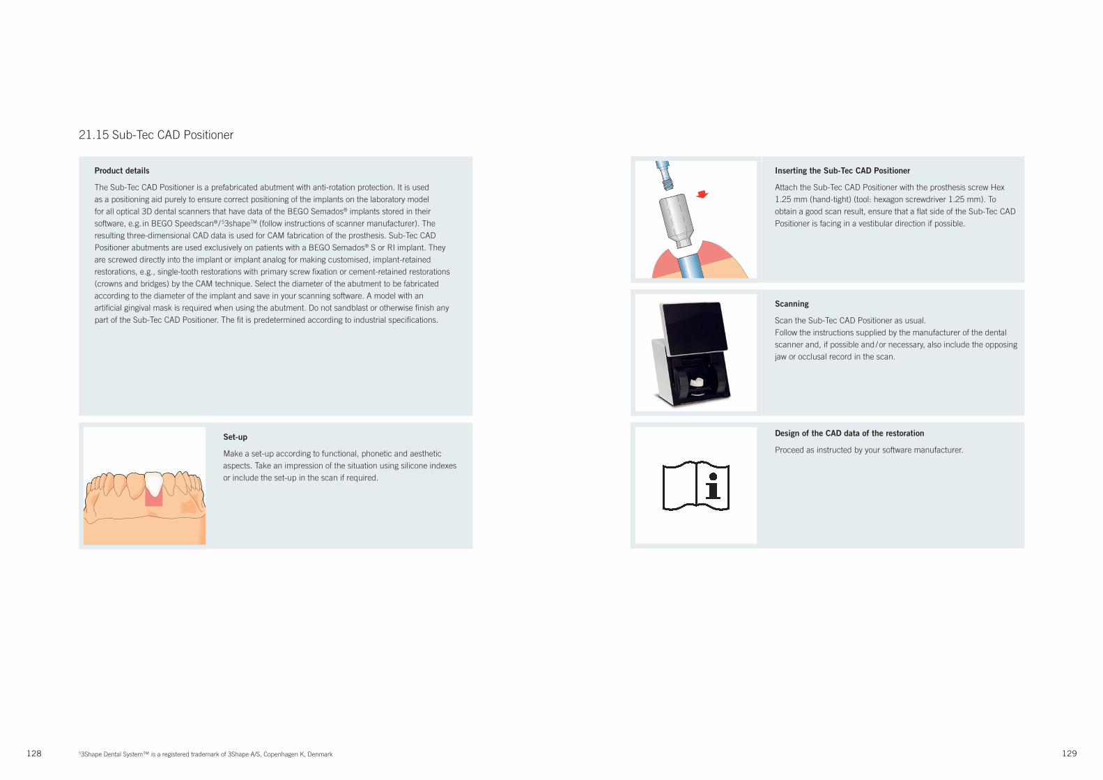
128 129
21.15 Sub-Tec CAD Positioner
Product details
The Sub-Tec CAD Positioner is a prefabricated abutment with anti-rotation protection. It is used
as a positioning aid purely to ensure correct positioning of the implants on the laboratory model
for all optical 3D dental scanners that have data of the BEGO Semados® implants stored in their
software, e.g. in BEGO Speedscan® / 53shapeTM (follow instructions of scanner manufacturer). The
resulting three-dimensional CAD data is used for CAM fabrication of the prosthesis. Sub-Tec CAD
Positioner abutments are used exclusively on patients with a BEGO Semados® S or RI implant. They
are screwed directly into the implant or implant analog for making customised, implant-retained
restorations, e.g., single-tooth restorations with primary screw fi xation or cement-retained restorations
(crowns and bridges) by the CAM technique. Select the diameter of the abutment to be fabricated
according to the diameter of the implant and save in your scanning software. A model with an
artifi cial gingival mask is required when using the abutment. Do not sandblast or otherwise fi nish any
part of the Sub-Tec CAD Positioner. The fi t is predetermined according to industrial specifi cations.
Inserting the Sub-Tec CAD Positioner
Attach the Sub-Tec CAD Positioner with the prosthesis screw Hex
1.25 mm (hand-tight) (tool: hexagon screwdriver 1.25 mm). To
obtain a good scan result, ensure that a fl at side of the Sub-Tec CAD
Positioner is facing in a vestibular direction if possible.
Set-up
Make a set-up according to functional, phonetic and aesthetic
aspects. Take an impression of the situation using silicone indexes
or include the set-up in the scan if required.
Design of the CAD data of the restoration
Proceed as instructed by your software manufacturer.
Scanning
Scan the Sub-Tec CAD Positioner as usual.
Follow the instructions supplied by the manufacturer of the dental
scanner and, if possible and / or necessary, also include the opposing
jaw or occlusal record in the scan.
53Shape Dental System™ is a registered trademark of 3Shape A/S, Copenhagen K, Denmark
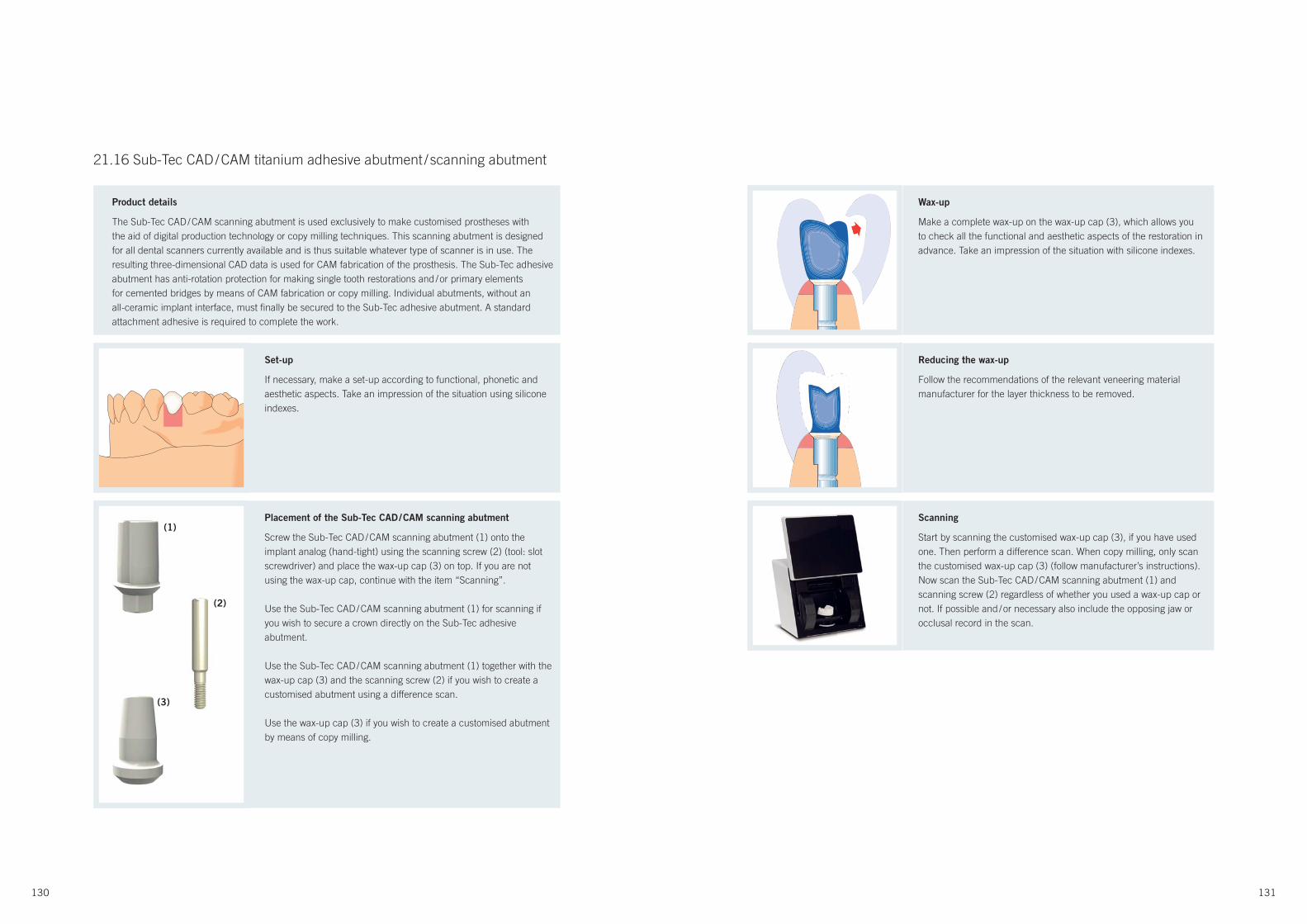
130 131
21.16 Sub-Tec CAD / CAM titanium adhesive abutment / scanning abutment
Reducing the wax-up
Follow the recommendations of the relevant veneering material
manufacturer for the layer thickness to be removed.
Wax-up
Make a complete wax-up on the wax-up cap (3), which allows you
to check all the functional and aesthetic aspects of the restoration in
advance. Take an impression of the situation with silicone indexes.
Scanning
Start by scanning the customised wax-up cap (3), if you have used
one. Then perform a difference scan. When copy milling, only scan
the customised wax-up cap (3) (follow manufacturer’s instructions).
Now scan the Sub-Tec CAD / CAM scanning abutment (1) and
scanning screw (2) regardless of whether you used a wax-up cap or
not. If possible and / or necessary also include the opposing jaw or
occlusal record in the scan.
Placement of the Sub-Tec CAD / CAM scanning abutment
Screw the Sub-Tec CAD / CAM scanning abutment (1) onto the
implant analog (hand-tight) using the scanning screw (2) (tool: slot
screwdriver) and place the wax-up cap (3) on top. If you are not
using the wax-up cap, continue with the item “Scanning”.
Use the Sub-Tec CAD / CAM scanning abutment (1) for scanning if
you wish to secure a crown directly on the Sub-Tec adhesive
abutment.
Use the Sub-Tec CAD / CAM scanning abutment (1) together with the
wax-up cap (3) and the scanning screw (2) if you wish to create a
customised abutment using a difference scan.
Use the wax-up cap (3) if you wish to create a customised abutment
by means of copy milling.
Set-up
If necessary, make a set-up according to functional, phonetic and
aesthetic aspects. Take an impression of the situation using silicone
indexes.
Product details
The Sub-Tec CAD / CAM scanning abutment is used exclusively to make customised prostheses with
the aid of digital production technology or copy milling techniques. This scanning abutment is designed
for all dental scanners currently available and is thus suitable whatever type of scanner is in use. The
resulting three-dimensional CAD data is used for CAM fabrication of the prosthesis. The Sub-Tec adhesive
abutment has anti-rotation protection for making single tooth restorations and / or primary elements
for cemented bridges by means of CAM fabrication or copy milling. Individual abutments, without an
all-ceramic implant interface, must fi nally be secured to the Sub-Tec adhesive abutment. A standard
attachment adhesive is required to complete the work.
(1)
(2)
(3)
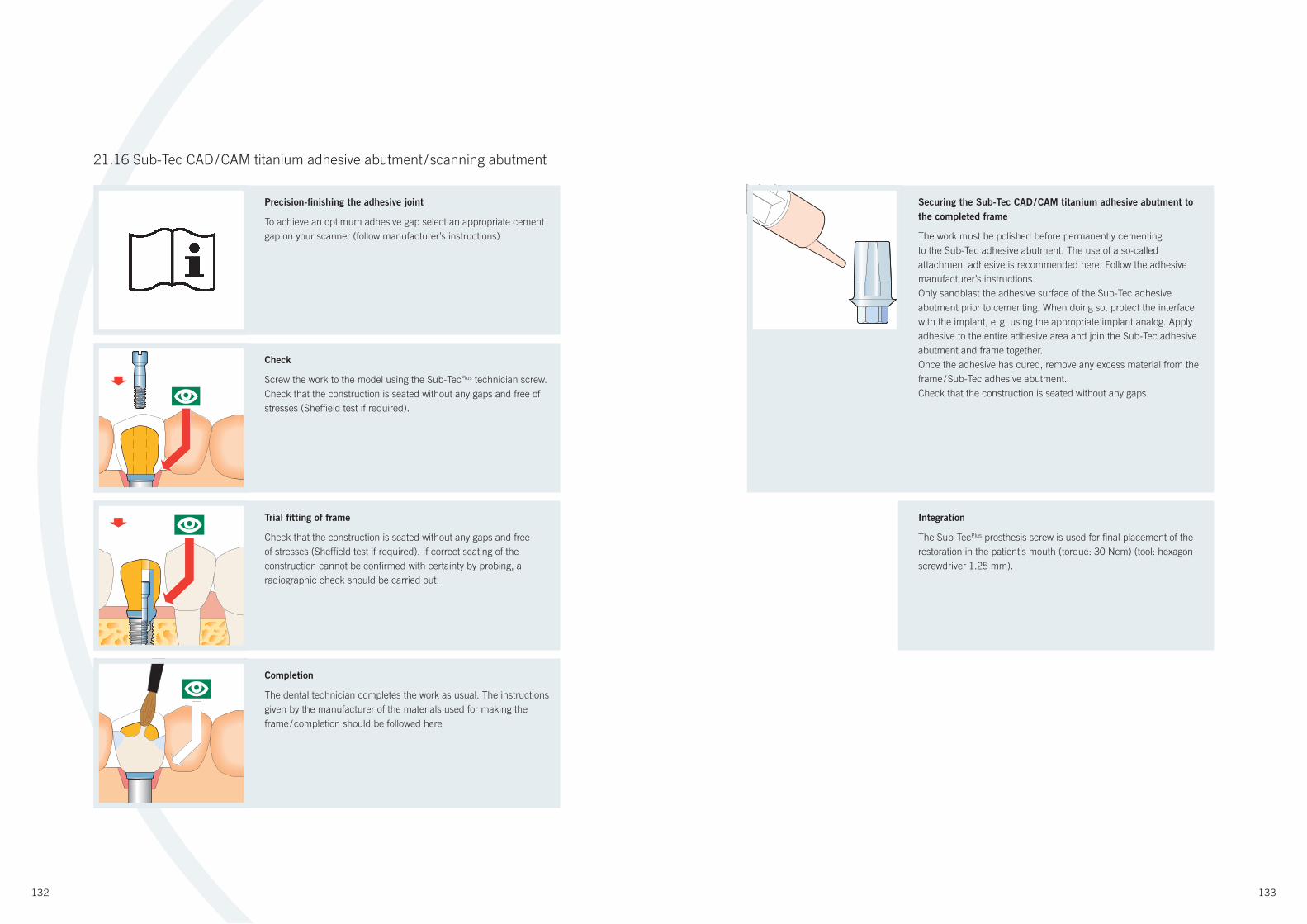
132 133
Securing the Sub-Tec CAD / CAM titanium adhesive abutment to
the completed frame
The work must be polished before permanently cementing
to the Sub-Tec adhesive abutment. The use of a so-called
attachment adhesive is recommended here. Follow the adhesive
manufacturer’s instructions.
Only sandblast the adhesive surface of the Sub-Tec adhesive
abutment prior to cementing. When doing so, protect the interface
with the implant, e. g. using the appropriate implant analog. Apply
adhesive to the entire adhesive area and join the Sub-Tec adhesive
abutment and frame together.
Once the adhesive has cured, remove any excess material from the
frame / Sub-Tec adhesive abutment.
Check that the construction is seated without any gaps.
Check
Screw the work to the model using the Sub-TecPlus technician screw.
Check that the construction is seated without any gaps and free of
stresses (Sheffi eld test if required).
Trial fi tting of frame
Check that the construction is seated without any gaps and free
of stresses (Sheffi eld test if required). If correct seating of the
construction cannot be confi rmed with certainty by probing, a
radiographic check should be carried out.
Completion
The dental technician completes the work as usual. The instructions
given by the manufacturer of the materials used for making the
frame / completion should be followed here
Integration
The Sub-TecPlus prosthesis screw is used for fi nal placement of the
restoration in the patient’s mouth (torque: 30 Ncm) (tool: hexagon
screwdriver 1.25 mm).
21.16 Sub-Tec CAD / CAM titanium adhesive abutment / scanning abutment
Precision-fi nishing the adhesive joint
To achieve an optimum adhesive gap select an appropriate cement
gap on your scanner (follow manufacturer’s instructions).
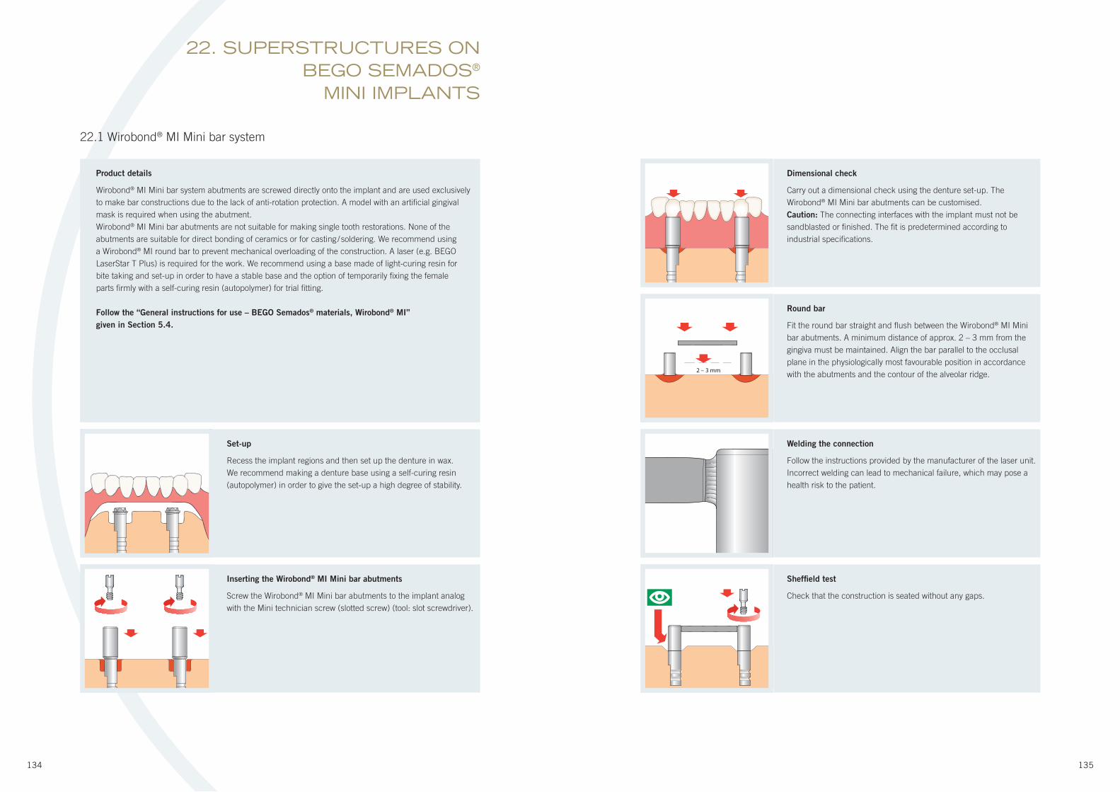
134 135
22.1 Wirobond® MI Mini bar system
2 – 3 mm
Round bar
Fit the round bar straight and fl ush between the Wirobond® MI Mini
bar abutments. A minimum distance of approx. 2 – 3 mm from the
gingiva must be maintained. Align the bar parallel to the occlusal
plane in the physiologically most favourable position in accordance
with the abutments and the contour of the alveolar ridge.
Dimensional check
Carry out a dimensional check using the denture set-up. The
Wirobond® MI Mini bar abutments can be customised.
Caution: The connecting interfaces with the implant must not be
sandblasted or fi nished. The fi t is predetermined according to
industrial specifi cations.
Welding the connection
Follow the instructions provided by the manufacturer of the laser unit.
Incorrect welding can lead to mechanical failure, which may pose a
health risk to the patient.
Set-up
Recess the implant regions and then set up the denture in wax.
We recommend making a denture base using a self-curing resin
(autopolymer) in order to give the set-up a high degree of stability.
Product details
Wirobond® MI Mini bar system abutments are screwed directly onto the implant and are used exclusively
to make bar constructions due to the lack of anti-rotation protection. A model with an artifi cial gingival
mask is required when using the abutment.
Wirobond® MI Mini bar abutments are not suitable for making single tooth restorations. None of the
abutments are suitable for direct bonding of ceramics or for casting / soldering. We recommend using
a Wirobond® MI round bar to prevent mechanical overloading of the construction. A laser (e.g. BEGO
LaserStar T Plus) is required for the work. We recommend using a base made of light-curing resin for
bite taking and set-up in order to have a stable base and the option of temporarily fi xing the female
parts fi rmly with a self-curing resin (autopolymer) for trial fi tting.
Follow the “General instructions for use – BEGO Semados® materials, Wirobond® MI”
given in Section 5.4.
22. SUPERSTRUCTURES ON BEGO SEMADOS®
MINI IMPLANTS
Sheffi eld test
Check that the construction is seated without any gaps.
Inserting the Wirobond® MI Mini bar abutments
Screw the Wirobond® MI Mini bar abutments to the implant analog
with the Mini technician screw (slotted screw) (tool: slot screwdriver).
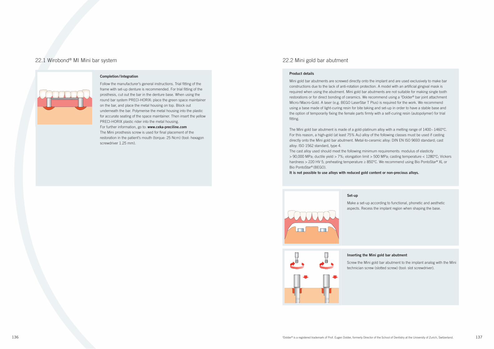
136 137
22.1 Wirobond® MI Mini bar system
Completion / Integration
Follow the manufacturer’s general instructions. Trial fi tting of the
frame with set-up denture is recommended. For trial fi tting of the
prosthesis, cut out the bar in the denture base. When using the
round bar system PRECI-HORIX: place the green space maintainer
on the bar, and place the metal housing on top. Block out
underneath the bar. Polymerise the metal housing into the plastic
for accurate seating of the space maintainer. Then insert the yellow
PRECI-HORIX plastic rider into the metal housing.
For further information, go to: www.ceka-preciline.com
The Mini prosthesis screw is used for fi nal placement of the
restoration in the patient’s mouth (torque: 25 Ncm) (tool: hexagon
screwdriver 1.25 mm).
22.2 Mini gold bar abutment
Set-up
Make a set-up according to functional, phonetic and aesthetic
aspects. Recess the implant region when shaping the base.
Inserting the Mini gold bar abutment
Screw the Mini gold bar abutment to the implant analog with the Mini
technician screw (slotted screw) (tool: slot screwdriver).
Product details
Mini gold bar abutments are screwed directly onto the implant and are used exclusively to make bar
constructions due to the lack of anti-rotation protection. A model with an artifi cial gingival mask is
required when using the abutment. Mini gold bar abutments are not suitable for making single tooth
restorations or for direct bonding of ceramics. We recommend using a 3Dolder® bar joint attachment
Micro / Macro-Gold. A laser (e.g. BEGO LaserStar T Plus) is required for the work. We recommend
using a base made of light-curing resin for bite taking and set-up in order to have a stable base and
the option of temporarily fi xing the female parts fi rmly with a self-curing resin (autopolymer) for trial
fi tting.
The Mini gold bar abutment is made of a gold-platinum alloy with a melting range of 1400 – 1460°C.
For this reason, a high-gold (at least 75% Au) alloy of the following classes must be used if casting
directly onto the Mini gold bar abutment. Metal-to-ceramic alloy: DIN EN ISO 9693 standard; cast
alloy: ISO 1562 standard, type 4.
The cast alloy used should meet the following minimum requirements: modulus of elasticity
> 90,000 MPa; ductile yield > 7%; elongation limit > 500 MPa; casting temperature < 1280°C; Vickers
hardness > 220 HV 5; preheating temperature ≥ 850°C. We recommend using Bio PontoStar® XL or
Bio PontoStar® (BEGO).
It is not possible to use alloys with reduced gold content or non-precious alloys.
3Dolder® is a registered trademark of Prof. Eugen Dolder, formerly Director of the School of Dentistry at the University of Zurich, Switzerland.
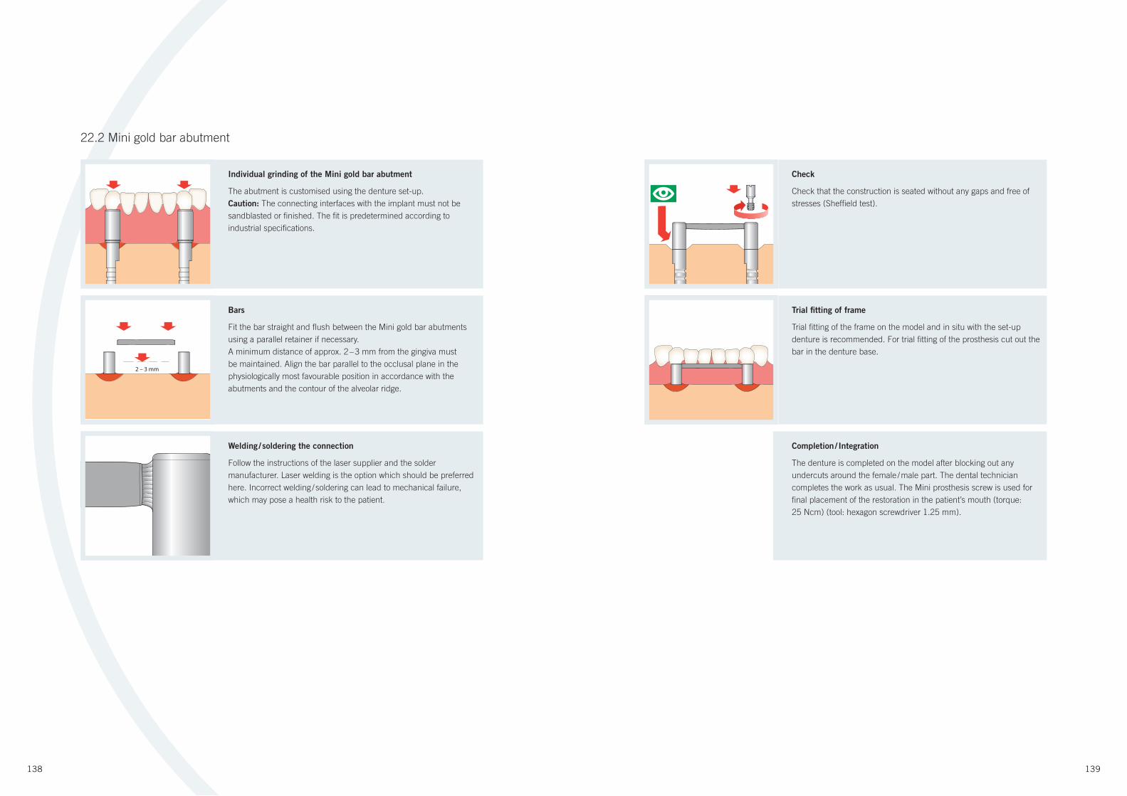
138 139
22.2 Mini gold bar abutment
Individual grinding of the Mini gold bar abutment
The abutment is customised using the denture set-up.
Caution: The connecting interfaces with the implant must not be
sandblasted or fi nished. The fi t is predetermined according to
industrial specifi cations.
Bars
Fit the bar straight and fl ush between the Mini gold bar abutments
using a parallel retainer if necessary.
A minimum distance of approx. 2 – 3 mm from the gingiva must
be maintained. Align the bar parallel to the occlusal plane in the
physiologically most favourable position in accordance with the
abutments and the contour of the alveolar ridge.
2 – 3 mm
Welding / soldering the connection
Follow the instructions of the laser supplier and the solder
manufacturer. Laser welding is the option which should be preferred
here. Incorrect welding / soldering can lead to mechanical failure,
which may pose a health risk to the patient.
Check
Check that the construction is seated without any gaps and free of
stresses (Sheffi eld test).
Trial fi tting of frame
Trial fi tting of the frame on the model and in situ with the set-up
denture is recommended. For trial fi tting of the prosthesis cut out the
bar in the denture base.
Completion / Integration
The denture is completed on the model after blocking out any
undercuts around the female / male part. The dental technician
completes the work as usual. The Mini prosthesis screw is used for
fi nal placement of the restoration in the patient’s mouth (torque:
25 Ncm) (tool: hexagon screwdriver 1.25 mm).
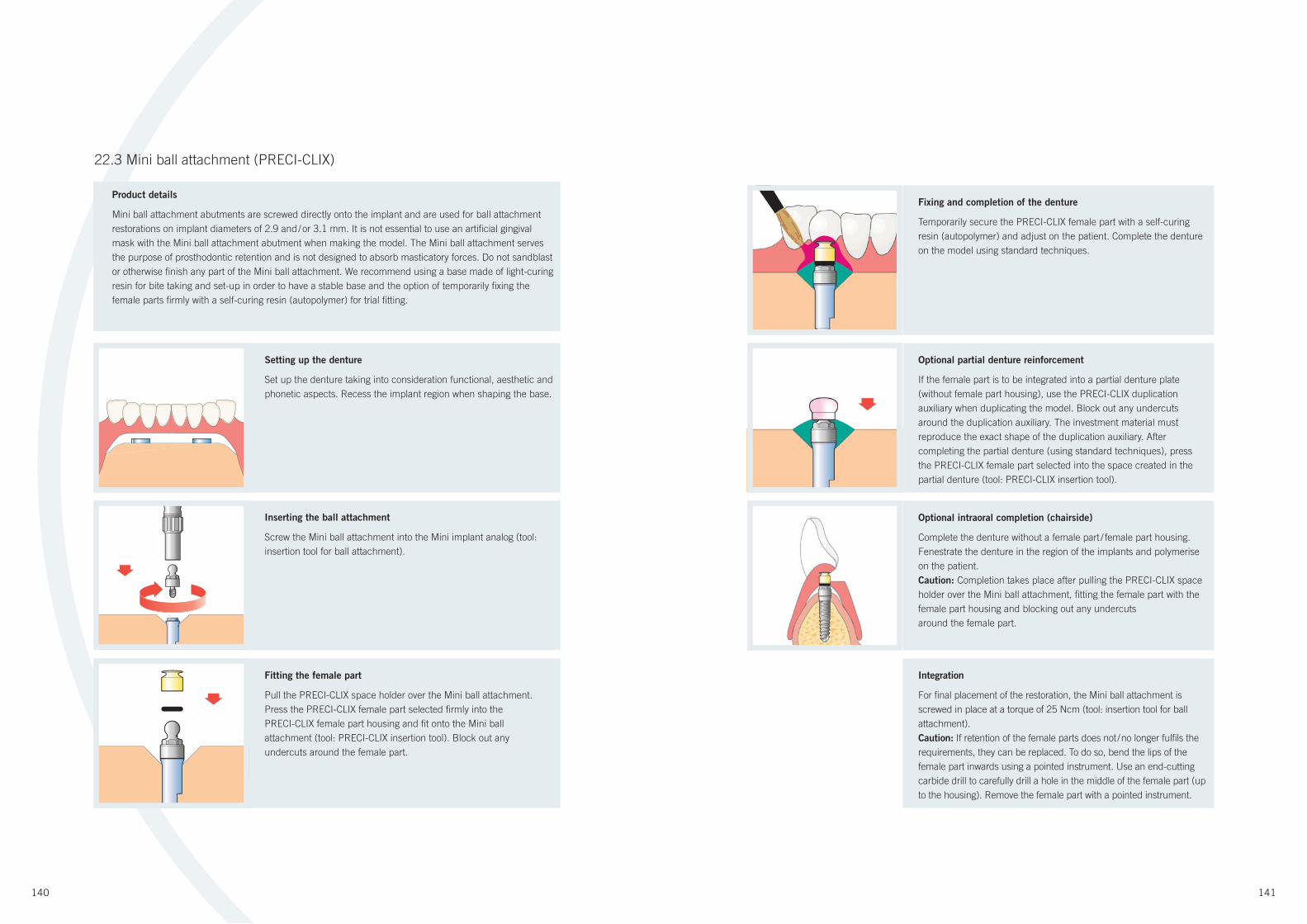
140 141
Setting up the denture
Set up the denture taking into consideration functional, aesthetic and
phonetic aspects. Recess the implant region when shaping the base.
Inserting the ball attachment
Screw the Mini ball attachment into the Mini implant analog (tool:
insertion tool for ball attachment).
Fitting the female part
Pull the PRECI-CLIX space holder over the Mini ball attachment.
Press the PRECI-CLIX female part selected fi rmly into the
PRECI-CLIX female part housing and fi t onto the Mini ball
attachment (tool: PRECI-CLIX insertion tool). Block out any
undercuts around the female part.
22.3 Mini ball attachment (PRECI-CLIX)
Product details
Mini ball attachment abutments are screwed directly onto the implant and are used for ball attachment
restorations on implant diameters of 2.9 and / or 3.1 mm. It is not essential to use an artifi cial gingival
mask with the Mini ball attachment abutment when making the model. The Mini ball attachment serves
the purpose of prosthodontic retention and is not designed to absorb masticatory forces. Do not sandblast
or otherwise fi nish any part of the Mini ball attachment. We recommend using a base made of light-curing
resin for bite taking and set-up in order to have a stable base and the option of temporarily fi xing the
female parts fi rmly with a self-curing resin (autopolymer) for trial fi tting.
Integration
For fi nal placement of the restoration, the Mini ball attachment is
screwed in place at a torque of 25 Ncm (tool: insertion tool for ball
attachment).
Caution: If retention of the female parts does not / no longer fulfi ls the
requirements, they can be replaced. To do so, bend the lips of the
female part inwards using a pointed instrument. Use an end-cutting
carbide drill to carefully drill a hole in the middle of the female part (up
to the housing). Remove the female part with a pointed instrument.
Optional partial denture reinforcement
If the female part is to be integrated into a partial denture plate
(without female part housing), use the PRECI-CLIX duplication
auxiliary when duplicating the model. Block out any undercuts
around the duplication auxiliary. The investment material must
reproduce the exact shape of the duplication auxiliary. After
completing the partial denture (using standard techniques), press
the PRECI-CLIX female part selected into the space created in the
partial denture (tool: PRECI-CLIX insertion tool).
Optional intraoral completion (chairside)
Complete the denture without a female part / female part housing.
Fenestrate the denture in the region of the implants and polymerise
on the patient.
Caution: Completion takes place after pulling the PRECI-CLIX space
holder over the Mini ball attachment, fi tting the female part with the
female part housing and blocking out any undercuts
around the female part.
Fixing and completion of the denture
Temporarily secure the PRECI-CLIX female part with a self-curing
resin (autopolymer) and adjust on the patient. Complete the denture
on the model using standard techniques.
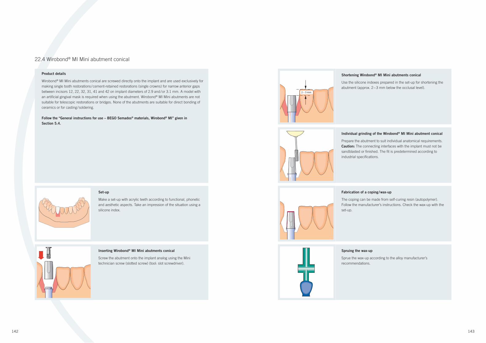
142 143
22.4 Wirobond® MI Mini abutment conical
Set-up
Make a set-up with acrylic teeth according to functional, phonetic
and aesthetic aspects. Take an impression of the situation using a
silicone index.
Inserting Wirobond® MI Mini abutments conical
Screw the abutment onto the implant analog using the Mini
technician screw (slotted screw) (tool: slot screwdriver).
Product details
Wirobond® MI Mini abutments conical are screwed directly onto the implant and are used exclusively for
making single tooth restorations / cement-retained restorations (single crowns) for narrow anterior gaps
between incisors 12, 22, 32, 31, 41 and 42 on implant diameters of 2.9 and / or 3.1 mm. A model with
an artifi cial gingival mask is required when using the abutment. Wirobond® MI Mini abutments are not
suitable for telescopic restorations or bridges. None of the abutments are suitable for direct bonding of
ceramics or for casting / soldering.
Follow the “General instructions for use – BEGO Semados® materials, Wirobond® MI” given in
Section 5.4.
2 – 3 mm
Shortening Wirobond® MI Mini abutments conical
Use the silicone indexes prepared in the set-up for shortening the
abutment (approx. 2 – 3 mm below the occlusal level).
Spruing the wax-up
Sprue the wax-up according to the alloy manufacturer’s
recommendations.
Individual grinding of the Wirobond® MI Mini abutment conical
Prepare the abutment to suit individual anatomical requirements.
Caution: The connecting interfaces with the implant must not be
sandblasted or fi nished. The fi t is predetermined according to
industrial specifi cations.
Fabrication of a coping / wax-up
The coping can be made from self-curing resin (autopolymer).
Follow the manufacturer’s instructions. Check the wax-up with the
set-up.
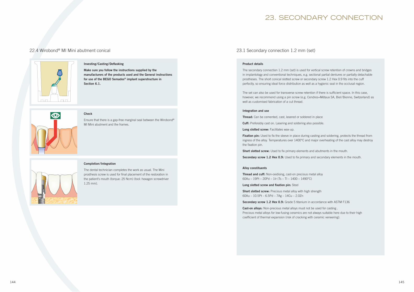
144 145
Investing / Casting / Defl asking
Make sure you follow the instructions supplied by the
manufacturers of the products used and the General instructions
for use of the BEGO Semados® implant superstructure in
Section 6.1.
Completion / Integration
The dental technician completes the work as usual. The Mini
prosthesis screw is used for fi nal placement of the restoration in
the patient’s mouth (torque: 25 Ncm) (tool: hexagon screwdriver
1.25 mm).
Check
Ensure that there is a gap-free marginal seal between the Wirobond®
MI Mini abutment and the frames.
22.4 Wirobond® MI Mini abutment conical 23.1 Secondary connection 1.2 mm (set)
23. SECONDARY CONNECTION
Product details
The secondary connection 1.2 mm (set) is used for vertical screw retention of crowns and bridges
in implantology and conventional techniques, e.g. sectional partial dentures or partially detachable
prostheses. The short conical slotted screw or secondary screw 1.2 Hex 0.9 fi ts into the cuff
perfectly, so ensuring ideal force distribution as well as a hygienic seal in the occlusal region.
The set can also be used for transverse screw retention if there is suffi cient space. In this case,
however, we recommend using a pin screw (e.g. Cendres+Métaux SA, Biel / Bienne, Switzerland) as
well as customised fabrication of a cut thread.
Integration and use
Thread: Can be cemented, cast, lasered or soldered in place
Cuff: Preferably cast on. Lasering and soldering also possible.
Long slotted screw: Facilitates wax-up.
Fixation pin: Used to fi x the sleeve in place during casting and soldering, protects the thread from
ingress of the alloy. Temperatures over 1400°C and major overheating of the cast alloy may destroy
the fi xation pin.
Short slotted screw: Used to fi x primary elements and abutments in the mouth.
Secondary screw 1.2 Hex 0.9: Used to fi x primary and secondary elements in the mouth.
Alloy constituents
Thread and cuff: Non-oxidising, cast-on precious metal alloy
60Au – 19Pt – 20Pd – 1Ir (Ts – Tl – 1400 – 1490°C)
Long slotted screw and fi xation pin: Steel
Short slotted screw: Precious metal alloy with high strength
60Au – 10.5Pt – 6.5Pd – 7Ag – 14Cu – 2.0Zn
Secondary screw 1.2 Hex 0.9: Grade 5 titanium in accordance with ASTM F136
Cast-on alloys: Non-precious metal alloys must not be used for casting .
Precious metal alloys for low-fusing ceramics are not always suitable here due to their high
coeffi cient of thermal expansion (risk of cracking with ceramic veneering).

146 147
23.1 Secondary connection 1.2 mm (set)
Casting and soldering
Casting: For investment, insert the fi xation pin in the investment
material to hold the threaded sleeve in place and to protect the
thread. First oxidise the fi xation pin before use (400°C / 10 minutes).
Next, coat the thread with colloidal graphite (e.g. Cendres+Métaux
SA, Biel / Bienne, Switzerland). Then insert into the threaded sleeve,
invest and cast. After casting, carefully remove the fi xation pin from
the threaded sleeve, keeping it straight. Should the fi xation pin break
after casting despite taking every care, it will dissolve in a heated
30% solution of hydrochloric acid (HCL) after about an hour.
Soldering: The fi xation pin is also used to produce the soldering
block. We recommend venting the blind hole to ensure complete
soldering around the threaded sleeve and to protect the thread
from the ingress of solder. To do so, drill a small hole or slot.
Secondary element: Integration of cuff by casting-on
Once the primary element has been milled and polished, work on
the secondary construction can then start. This involves inserting
the cuff with the screw, which has already been shortened as
required. The cuff is integrated in the wax-up. A fi ne notch should
be made at the junction between the wax and the cuff to prevent
the ingress of molten alloy as far as possible during subsequent
casting-on. Then invest, cast and polish.
Note: The investment material will give the cuff suffi cient retention
if investment has been carried out properly without voids.
Primary element: Inserting the sleeve
Wax-up of the primary crown or bridge element is followed by
placement of the threaded sleeve taking account of anatomical,
functional and aesthetic principles. The threaded sleeve must be
completely surrounded by wax. A fi ne notch can be made at the
junction between the wax and the sleeve to prevent the ingress of
alloy during casting-on.
Important: Check the occlusion with the cuff and the inserted
screw (short slotted screw or secondary screw 1.2 Hex 0.9). The
head of the screw must not be in contact with the opposing tooth.
If necessary, the head of the screw can be individually shortened
provided that it can still be gripped by the spanner.
Cementing and lasering
When waxing up the primary crown or bridge element make
sure that suffi cient material is available for drilling at the
screw support. After making a pilot hole with a centring bur
(e.g. Cendres+Métaux SA, Biel / Bienne, Switzerland) the end
dimension drill hole can be made directly with the twist drill
selected according to the diameter of the screw (oil well and lift
at intervals). Once the bonding surfaces have been sandblasted
and cleaned, cement the threaded sleeve with a suitable adhesive
(follow manufacturer’s instructions).
Instead of cementing the threaded sleeve, it can also be lasered
in place. Filler material from the crown alloy should be used
to ensure a secure connection. There should be absolutely no
leakage at the laser-welded seam to prevent localised pitting
corrosion.

BEGO Implant Systems GmbH & Co. KG
Wilhelm-Herbst-Str. 1 · 28359 Bremen · Germany
Phone +49 (0)421 20 28-246
Fax +49 (0)421 20 28-265
www.bego-implantology.com
E-mail: [email protected]
Ord
er
no.: 8
24
78
, Vers
. 0
1 ·
© 2
01
0 by
BE
GO
·
Septe
mber
20
10
·
ww
w.a
dw
ork
.de
Official care provider to the German Olympic teams since 2002
PROSTHODONTIC MANUAL
PR
OS
TH
OD
ON
TIC
M
AN
UA
L
www.bego-implantology.com