prosthetic hand using shape memory alloy type artificial ... · abstract —the purpose of ......
TRANSCRIPT
Abstract—The purpose of our research was to develop a
prosthetic hand using shape memory alloy (SMA) type artificial
muscle (AM). This paper presents the following experiments in
the development of the prosthetic hand: 1) an experiment
determining the properties of the SMA type AM, 2) the
development of the prosthetic fingers, 3) based on the results of
the first two experiments, the development of the prosthetic
hand. Finally, an experiment investigating the usefulness of the
prosthetic hand is presented.
Index Terms— design, experiment, prosthetic finger,
prosthetic hand, shape memory alloy
I. INTRODUCTION
The functionality of the human hand ensures optimal
performance of activities of daily living. Individuals with
hand disabilities are limited in their ability to perform work.
In these situations a prosthetic hand may be useful. Several
types of prosthetic hands have been proposed. For example,
there are prosthetic hands that are only cosmetic and
hook-shaped hands that have limited functionality[1]
. The
characteristics expected of prosthetic hands are that they
should be comfortable, useful for manipulating objects and
light weight. The purpose of our research was to develop a
new type of prosthetic hand that could be used by individuals
with a hand disability.
Electric motors are generally used as actuators for
conventional prosthetic or robot hands. It is easy to control
the motions of the prosthetic hand using an electric motor.
However, prosthetic hands that have more than one motor are
heavy.
Recently, various actuators using air pressure type or
polymer type AMs have been proposed. Recently, a robot
hand using air pressure type AM was developed[2]
. However,
the system was large and heavy as it required an air
compressor and a gas container to store the compressed air.
The SMA type AM has potential for prosthetic hand design
as it has a large force-to-mass ratio and therefore the hand can
be light. In addition, SMA type AM has no gear train and
therefore movement is silent. Therefore, we used SMA type
AM (BioMetal[3]
) as an actuator in the development of a
prosthetic hand.
All authors are with Mechanical Engineering Course, Graduate School of
Science and Engineering, Ehime University, 3 Bunkyo-cho, Matsuyama
790-8577, Japan. E-mail: Shingo Okamoto < [email protected]>,
Jae Hoon Lee < [email protected]>
II. PROPERTIES OF SMA TYPE ARTIFICIAL MUSCLE
A. Loading Test
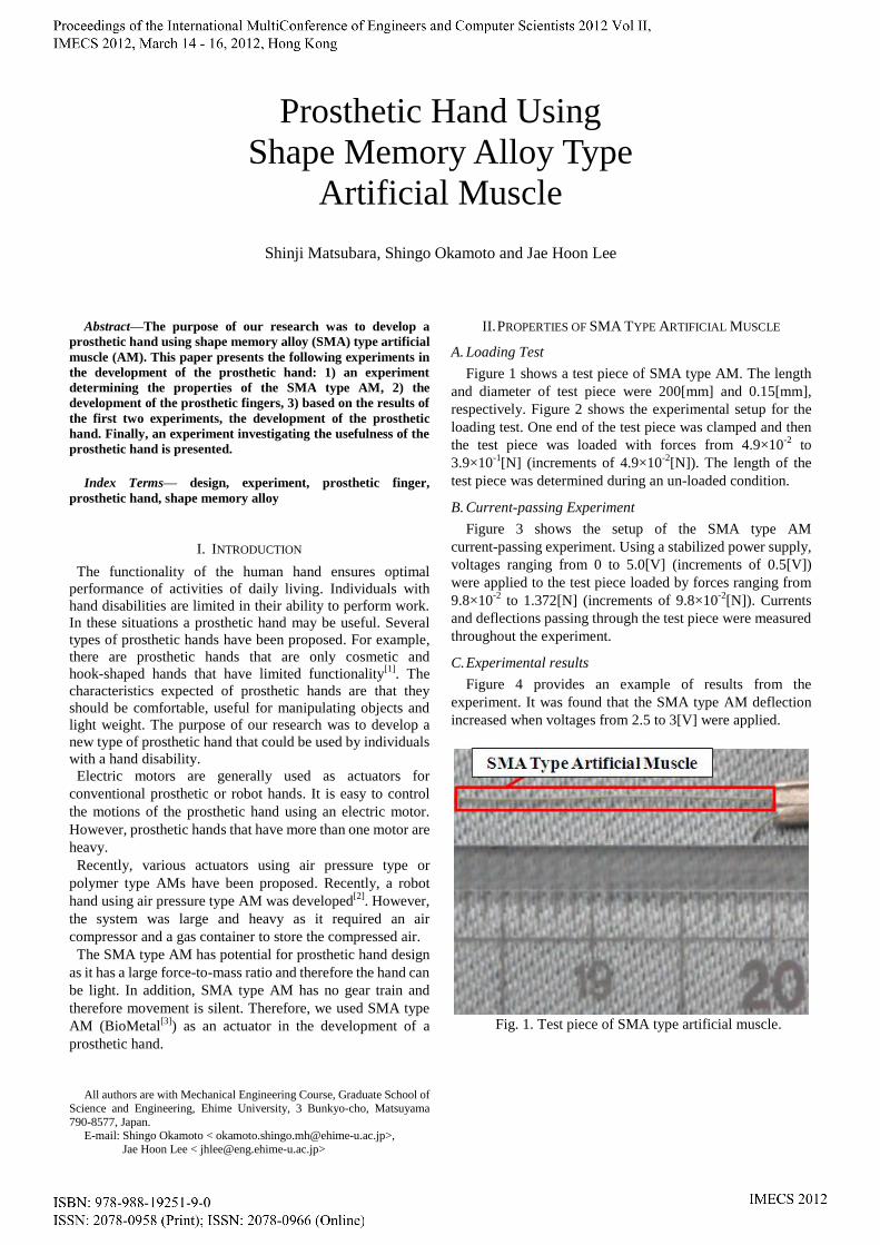
Figure 1 shows a test piece of SMA type AM. The length
and diameter of test piece were 200[mm] and 0.15[mm],
respectively. Figure 2 shows the experimental setup for the
loading test. One end of the test piece was clamped and then
the test piece was loaded with forces from 4.9×10⁻²
to
3.9×10⁻¹
[N] (increments of 4.9×10⁻²
[N]). The length of the
test piece was determined during an un-loaded condition.
B. Current-passing Experiment
Figure 3 shows the setup of the SMA type AM
current-passing experiment. Using a stabilized power supply,
voltages ranging from 0 to 5.0[V] (increments of 0.5[V])
were applied to the test piece loaded by forces ranging from
9.8×10⁻²
to 1.372[N] (increments of 9.8×10⁻²
[N]). Currents
and deflections passing through the test piece were measured
throughout the experiment.
C. Experimental results
Figure 4 provides an example of results from the
experiment. It was found that the SMA type AM deflection
increased when voltages from 2.5 to 3[V] were applied.
Fig. 1. Test piece of SMA type artificial muscle.
Prosthetic Hand Using
Shape Memory Alloy Type
Artificial Muscle
Shinji Matsubara, Shingo Okamoto and Jae Hoon Lee

III. DEVELOPMENT OF PROSTHETIC FINGER
A. Mechanism of Prosthetic Fingers
The human finger consists of three links, which are
connected by three joints: the distal inter-pharangeal (DIP)
proximal inter-pharangeal (PIP) and Metacarpophalangeal
(MP) joints (Figure 5). The prosthetic finger that we
developed had the same structure as human fingers. The
prosthetic finger was operated by two SMA type AMs. One
was attached to the second link for rotation of the DIP and
PIP joints. The second was attached to the third link and was
responsible for rotation of all joints in the finger.
Fig. 2. Setup of load experiment.
Fig. 3. Deformation of the SMA type AM after a voltage of
4.0[V] was applied to it while loaded by 1.372[N] of force.
Fig. 4. The relationship between deflection and voltage when
the test piece was under a load of 1.372[N].
The two SMA type AMs were installed inside the finger
and several stoppers were used for the generation of effective
torque at the joints. The result was that all three joints of the
finger could be controlled by the two SMA type AMs to
allow the finger to grasp an object. Additionally, to allow
extension of the finger, a spring, situated in the palm of the
hand, was attached via a wire to SMA type AM that was
situated in the third link (Figure 5). Figure 6 shows the
motion of the prosthetic finger.
To ensure that the SMA type AM was isolated to allow
independent operation, Teflon films were inserted between
the SMA type AMs in the finger mechanism. The stroke of
each SMA type AM was approximately 5% of its natural
length. Therefore to ensure that there was appropriate stroke
for finger motion, small pulleys that lengthened the SMA
type AM were inserted in the palm.
Figure 7 and Figure 8 show the first finger of the prosthetic
hand. Figure 9 and Figure 10 show the fourth finger of
prosthetic hand.
B. Prosthetic Finger Experiment
Figure 11 and Figure 12 show the motion of the prosthetic
finger. We examined the motion of the prosthetic finger when
each link of the prosthetic finger was fixed. From these
experiments we demonstrated that the prosthetic finger could
grasp an object.
Fig. 5. Human finger and prosthetic finger.
Fig. 6. Motion of the prosthetic finger.
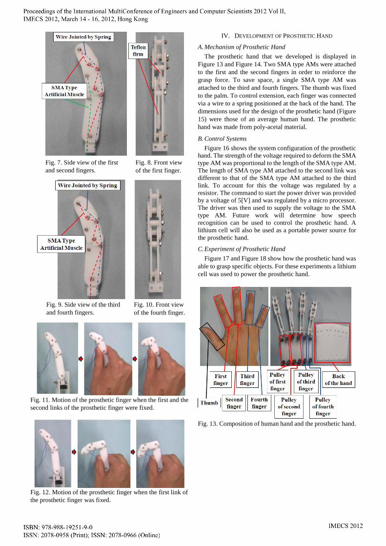
Fig. 11. Motion of the prosthetic finger when the first and the
second links of the prosthetic finger were fixed.
Fig. 12. Motion of the prosthetic finger when the first link of
the prosthetic finger was fixed.
IV. DEVELOPMENT OF PROSTHETIC HAND
A. Mechanism of Prosthetic Hand
The prosthetic hand that we developed is displayed in
Figure 13 and Figure 14. Two SMA type AMs were attached
to the first and the second fingers in order to reinforce the
grasp force. To save space, a single SMA type AM was
attached to the third and fourth fingers. The thumb was fixed
to the palm. To control extension, each finger was connected
via a wire to a spring positioned at the back of the hand. The
dimensions used for the design of the prosthetic hand (Figure
15) were those of an average human hand. The prosthetic
hand was made from poly-acetal material.
B. Control Systems
Figure 16 shows the system configuration of the prosthetic
hand. The strength of the voltage required to deform the SMA
type AM was proportional to the length of the SMA type AM.
The length of SMA type AM attached to the second link was
different to that of the SMA type AM attached to the third
link. To account for this the voltage was regulated by a
resistor. The command to start the power driver was provided
by a voltage of 5[V] and was regulated by a micro processor.
The driver was then used to supply the voltage to the SMA
type AM. Future work will determine how speech
recognition can be used to control the prosthetic hand. A
lithium cell will also be used as a portable power source for
the prosthetic hand.
C. Experiment of Prosthetic Hand
Figure 17 and Figure 18 show how the prosthetic hand was
able to grasp specific objects. For these experiments a lithium
cell was used to power the prosthetic hand.
Fig. 13. Composition of human hand and the prosthetic hand.
Fig. 7. Side view of the first
and second fingers.
Fig. 8. Front view
of the first finger.
Fig. 9. Side view of the third
and fourth fingers.
Fig. 10. Front view
of the fourth finger.

Fig. 14. Side view of the prosthetic hand.
Fig. 15. Dimensions of the prosthetic hand.
V. CONCLUSIONS
We have developed a light and quiet prosthetic hand using
SMA type AM. In future work the number of SMA type AMs
will be increased to improve the grasp force of the prosthetic
hand. This will also improve accuracy and reduce the heat
generated, allowing the hand to have real-life applications.
Fig. 16. System configuration of the prosthetic hand.
Fig. 17. The prosthetic hand grasping a plastic ball.
Fig. 18. The prosthetic hand grasping a plastic cup.
REFERENCES
[1] Nagano prefectural Rehabilitation Center
http://www.pref.nagano.jp/xsyakai/reha/reha_po/reha_po-view.htm [2] Y. Kimura, T. Nakamura, “Development of the robot hand using wire
type artificial rubber muscle” JSME, No. 11-5, pp.1A1-106, 2011.
[3] Toki Corporation http://www.toki.co.jp/biometal/index.php