propulsion systems laboratory engine icing … systems laboratory engine icing modifications thomas...
TRANSCRIPT

National Aeronautics and Space Administration
www.nasa.gov
National Aeronautics and Space Administration
www.nasa.gov
Propulsion Systems
Laboratory
Engine Icing Modifications
Thomas R. Hoffman
PSL Facility Manager
John H. Glenn Research Center at Lewis Field
2011 Annual Technical Meeting
May 10–12, 2011
St. Louis, MO
https://ntrs.nasa.gov/search.jsp?R=20150010141 2018-06-03T21:41:47+00:00Z

National Aeronautics and Space Administration
www.nasa.gov
Propulsion Systems Laboratory
• Two test sections share
common inlet and exhaust
• Continuous Operation at
high air flow rates
Altitude 90,000 ft (-90 deg F)
PSL-3 Mach 3.0 (600 deg F)
PSL-4 Mach 4.0 (1000 deg F)
• Six component thrust system (50,000 lbf)
• Real time, high speed data
acquisition and display
NASA Glenn’s Propulsion Systems Lab (PSL) is one of the Nation’s
Premier Direct Connect Altitude Simulation Facilities for Full-Scale
Gas Turbine Engines and Propulsion System Research
Location of Icing Upgrade

National Aeronautics and Space Administration
www.nasa.gov 3
• Main Icing System Installation (complete 6/2011)
– Construction at 90% complete
– Spray bar installation nearly complete
• Test Cell Calibration/Engine Transition Hardware (complete 11/2011)
– Fabrication set to begin
– Includes instrumentation, camera systems
• Integrated Systems Test (complete 1/2012)
– System Checkouts
– Full up Icing System Integrity and Check
• Calibration Test (complete 6/2012)
– Verify Requirements are met and easily achievable
– Document System Capabilities
• Validation Test (start 10/2012)
– Seeking a cooperative test with engine manufacturer
– Validate Against Existing Flight Data
Progress/PlanPSL Icing System

National Aeronautics and Space Administration
www.nasa.gov
ObjectivesPSL Icing System
Establishment of a ground-based, ice-crystal environment, engine
test capability that includes altitude effects.
Better understanding on how ice accretes inside an engine and
how it effects engine performance and operability.
Investigation and development of test methods and techniques that
enable the effective and efficient study of engine icing due to ice-
crystals along the path of airflow through the core of an engine.
Development of validation data sets required to enable the
creation of a system of computer codes that can be specifically
applied to assess engine icing susceptibility as well as engine
performance and operability effects.
Collaboration with industry partners to utilize system to meet above
objectives and facility utilization goals.
4

National Aeronautics and Space Administration
www.nasa.gov
Technical ChallengesPSL Icing System
Design and build an icing system that is versatile so it can be refined
to meet developing engine icing requirements.
An assessment of PSL’s capability to simulate conditions that lead to
engine core icing events.
The establishment of conditions inside the engine under which ice
can accrete, both before and after accretion occurs at a given point in
the simulated flight trajectory (altitude).
Test methods for conducting pertinent engine core icing tests in PSL.
The creation of methods and techniques needed to measure/monitor
engine core ice accretions.
A complete set of validation data sets including engine design
geometry and operating conditions as well as atmospheric conditions
for simulation of engine core icing events.
A knowledgebase of engine core icing from which engineering tools
to address the problem can be further developed.
5

National Aeronautics and Space Administration
www.nasa.gov 6
Technical ApproachPSL Icing System
Specified Requirement
Specification Minimum Maximum
Altitude (pressure) 4000 ft 40,000 ft
Inlet Total Temperature -60°F 15°F
Mach Number 0.15 0.80
Air Flow Rate 10 lbm/sec 330 lbm/sec
IWC (icing water content) 0.5 g/m3 9.0 g/m3
MVD (median volumetric diameter) 40µ 60µ
Run Time Continuous up to 45 minutes
Icing system was designed and built to requirements estab-
lished by collaboration with industry and government experts

National Aeronautics and Space Administration
www.nasa.gov 7
Proof of concept tests, instrumentation evaluation and PSL
simulation and computer simulation were performed by NASA
and Cox & Co.
Schematic of Cox and Co. Icing facility.
AnalysisPSL Icing System

National Aeronautics and Space Administration
www.nasa.gov 8
AnalysisPSL Icing System
Parametrics include tunnel speed and
temperature, nozzle type, cooling air pres-
sure and temperature, spray bar atomizing
air and water pressures and temperatures.
FSSP and OAP used to determine median
volume droplet size (MVD) and distribution
Multi-wire probe used to determine liquid
and total water content (LWC, TWC) and
freeze fraction.
Prototype Spraybar

National Aeronautics and Space Administration
www.nasa.gov 9
AnalysisPSL Icing System
Grid establishes cloud
size, uniformity and
center for instrument
placement.

National Aeronautics and Space Administration
www.nasa.gov 10
AnalysisPSL Icing System
Computer simulations with Fluent Software were
performed and evaluated by NASA and Cox & Co.

National Aeronautics and Space Administration
www.nasa.gov 11
Test Cell 3
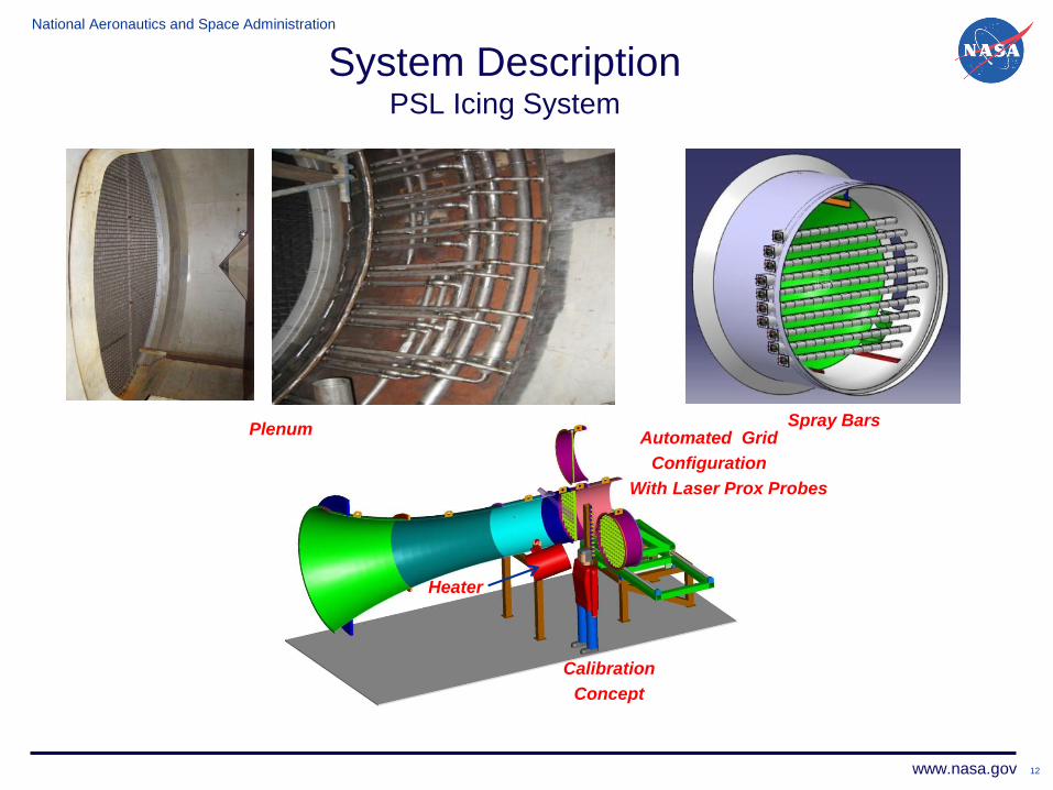
System DescriptionIcing Configuration
National Aeronautics and Space Administration
www.nasa.gov
Calibration
Concept
Automated Grid
Configuration
With Laser Prox Probes
Heater
12
PlenumSpray Bars
System DescriptionPSL Icing System

National Aeronautics and Space Administration
www.nasa.gov 13
System DescriptionPSL Icing System
5 cameras inside the plenum will provide a wide angle view of the
spray bars, nozzles, plenum surfaces and ice cloud.
To be displayed and recorded in control room for system integrity
and ice cloud documentation.
National Aeronautics and Space Administration
www.nasa.gov 14
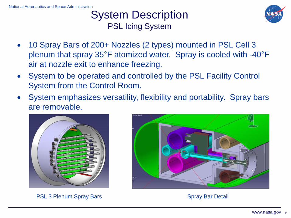
10 Spray Bars of 200+ Nozzles (2 types) mounted in PSL Cell 3
plenum that spray 35°F atomized water. Spray is cooled with -40°F
air at nozzle exit to enhance freezing.
System to be operated and controlled by the PSL Facility Control
System from the Control Room.
System emphasizes versatility, flexibility and portability. Spray bars
are removable.
PSL 3 Plenum Spray Bars Spray Bar Detail
System DescriptionPSL Icing System

National Aeronautics and Space Administration
www.nasa.gov 15
Spray Bars being fabricated
Spray Bar Detail
System DescriptionPSL Icing System

National Aeronautics and Space Administration
www.nasa.gov 16
Subsystems Design Summary
Glycol HX
Glycol HX
Glycol HX
LN2 Cooler
Tank
Cooling Loop
Water
Particles
Atomizing Air
Cooling Air
Spray Bar
Spray Bar
Spray Bar
35 °F
35 °F
35 °F
-40 °F
System DescriptionPSL Icing System

National Aeronautics and Space Administration
www.nasa.gov 17
Icing system control pages allow one operator to set desired conditions.
Icing System Control Spray Bar Control
System ControlsPSL Icing System
Spray Bar Nozzle Pattern Control

National Aeronautics and Space Administration
www.nasa.gov 18
Questions?/Comments !
Contact Tom Hoffman, PSL Facility Manager
216-433-5637, [email protected]

National Aeronautics and Space Administration
www.nasa.gov 19
Backup Slides
Contact Tom Hoffman, PSL Facility Manager
216-433-5637, [email protected]

National Aeronautics and Space Administration
www.nasa.gov 20
System DescriptionPSL Icing System
Water TankAir Dryer
Cooling/Atomizing Air HX
Glycol Chiller
Controls
Outside Test Cell
Water Supply and Return Pipe
Atomizing and Cooling Air Supply