proprietary booklet of valveworks usa. do … · to hydrostatically test the valve body to full api...
TRANSCRIPT
[email protected] BOOKLET OF VALVEWORKS USA. DO NOT REPRODUCE WITHOUT EXPLICIT PERMISSION.
Page 1 [email protected]
MODEL FM2 SERVICE AND OPERATION MANUAL
PROPRIETARY BOOKLET OF VALVEWORKS USA. DO NOT REPRODUCE WITHOUT EXPLICIT PERMISSION.
[email protected] BOOKLET OF VALVEWORKS USA. DO NOT REPRODUCE WITHOUT EXPLICIT PERMISSION.
Page 2
MODEL FM2 SERVICE AND OPERATION MANUAL
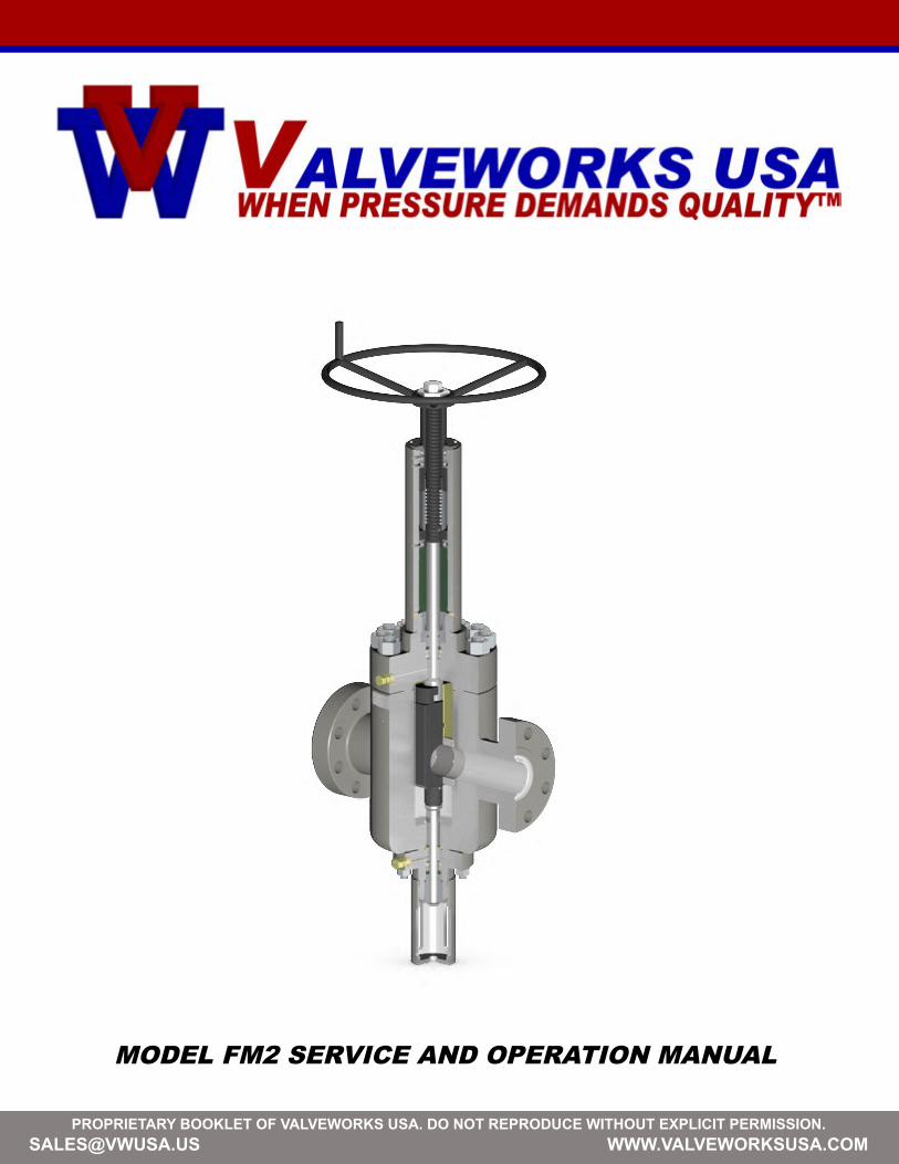
INTRODUCTIONIn appreciation to our customer for purchasing our product, we have prepared this OperationManual to assist you in the Operation, Maintenance, Assembly and Installation of the ValveworksUSA API 6A Model FM2 Gate Valve. We encourage following the recommendations in this bookletto attain the best possible service from our product, which is designed and proven to offer theservice one can expect of a quality product.To contact a representative for more specific information pertaining to a special problem:
1650 SWAN LAKE ROADBOSSIER CITY, LA USA 71111
PHONE 318-425-0266FAX 318-425-0934TOLL FREE 888-425-0266EMAIL [email protected] WWW.VALVEWORKSUSA.COM
QUALITYValveworks USA management and employees are committed to continually improve the effectiveness of our quality management system to produce a quality assured product which meets or exceeds our customer’s expectations and requirements.
SAFETYCaution must be taken as to the surrounding area and its potential dangers of projectiles.Pressure kills! Even a loose, stand alone valve may contain trapped pressure which will turn any component into a projectile missile when disassembled, causing injury or death. Never stand over a component or in its path of release during assembly. Always operate the valves from the open to close position slowly releasing trapped pressure. Always remove fittings first, taking extreme caution to their potential danger as a projectile. If the valve is frozen and can not be operated, take extreme caution to the disassembly of the components. Weighted blankets or protective screens and shields should be utilized. Caution should be taken when handling components during disassembly and assembly, as most components are heavy, greasy, hard to handle and have edges which can cause injury. Always be cautious of how the valve is positioned and standing. Be sure the valve is secured in position so there is no possible chance of tipping over. Never apply test pressure above the manufacturers rated working pressure. The shell test pressure above the working pressure has already been tested by the manufacturer and is not required after the initial assembly test of the valve. The manufacturer has already verified the quality of the valve shell body components and will void the warranty from the manufacturer if the valve is pressure tested above the rated working pressure indicated for the valve. Always wear steel toes shoes, hard hat, eye and ear protection while performing repairs.
[email protected] BOOKLET OF VALVEWORKS USA. DO NOT REPRODUCE WITHOUT EXPLICIT PERMISSION.
Page 3
MODEL FM2 SERVICE AND OPERATION MANUAL
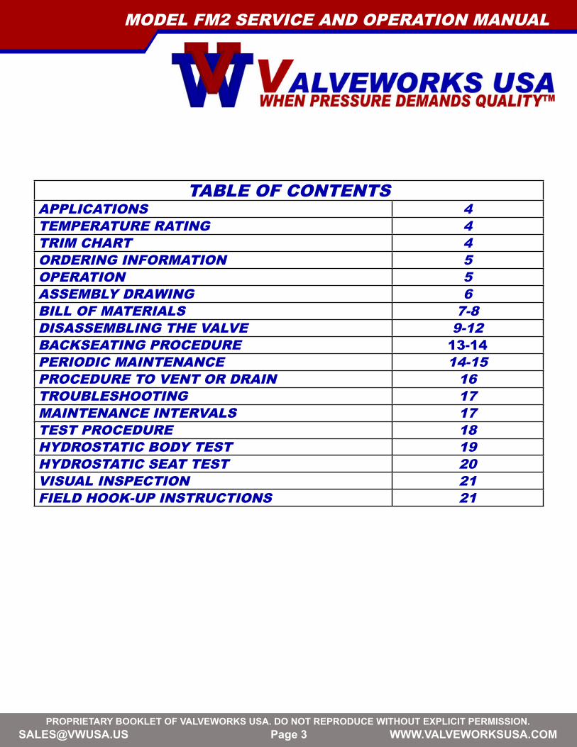
TABLE OF CONTENTSAPPLICATIONS 4TEMPERATURE RATING 4TRIM CHART 4ORDERING INFORMATION 5OPERATION 5ASSEMBLY DRAWING 6BILL OF MATERIALS 7-8DISASSEMBLING THE VALVE 9-12BACKSEATING PROCEDURE 13-14PERIODIC MAINTENANCE 14-15PROCEDURE TO VENT OR DRAIN 16TROUBLESHOOTING 17MAINTENANCE INTERVALS 17TEST PROCEDURE 18HYDROSTATIC BODY TEST 19HYDROSTATIC SEAT TEST 20VISUAL INSPECTION 21FIELD HOOK-UP INSTRUCTIONS 21
[email protected] BOOKLET OF VALVEWORKS USA. DO NOT REPRODUCE WITHOUT EXPLICIT PERMISSION.
Page 4
MODEL FM2 SERVICE AND OPERATION MANUAL
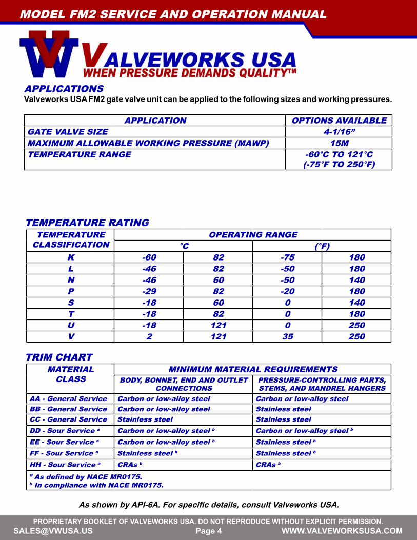
APPLICATIONSValveworks USA FM2 gate valve unit can be applied to the following sizes and working pressures.
APPLICATION OPTIONS AVAILABLEGATE VALVE SIZE 4-1/16”MAXIMUM ALLOWABLE WORKING PRESSURE (MAWP) 15MTEMPERATURE RANGE -60°C TO 121°C
(-75°F TO 250°F)
TEMPERATURE RATINGTEMPERATURE
CLASSIFICATIONOPERATING RANGE
°C (°F)K -60 82 -75 180L -46 82 -50 180N -46 60 -50 140P -29 82 -20 180S -18 60 0 140T -18 82 0 180U -18 121 0 250V 2 121 35 250
TRIM CHARTMATERIAL
CLASSMINIMUM MATERIAL REQUIREMENTS
BODY, BONNET, END AND OUTLETCONNECTIONS
PRESSURE-CONTROLLING PARTS, STEMS, AND MANDREL HANGERS
AA - General Service Carbon or low-alloy steel Carbon or low-alloy steelBB - General Service Carbon or low-alloy steel Stainless steelCC - General Service Stainless steel Stainless steelDD - Sour Service a Carbon or low-alloy steel b Carbon or low-alloy steel b
EE - Sour Service a Carbon or low-alloy steel b Stainless steel b
FF - Sour Service a Stainless steel b Stainless steel b
HH - Sour Service a CRAs b CRAs b
a As defined by NACE MR0175.b In compliance with NACE MR0175.
As shown by API-6A. For specific details, consult Valveworks USA.

[email protected] BOOKLET OF VALVEWORKS USA. DO NOT REPRODUCE WITHOUT EXPLICIT PERMISSION.
Page 5
MODEL FM2 SERVICE AND OPERATION MANUAL
ORDERING INFORMATIONThe following information should be provided with any request for quote or order placement of Valveworks USA FM2 Gate Valves: • API 6A Requirements (PR-PSL)• Temperature Rating (API 6A)• Material (API 6A)• Any Special Test Requirements• Any Special Material Requirements• Any Special Coating or Protection Requirements• Other Specifications and/or Certifications
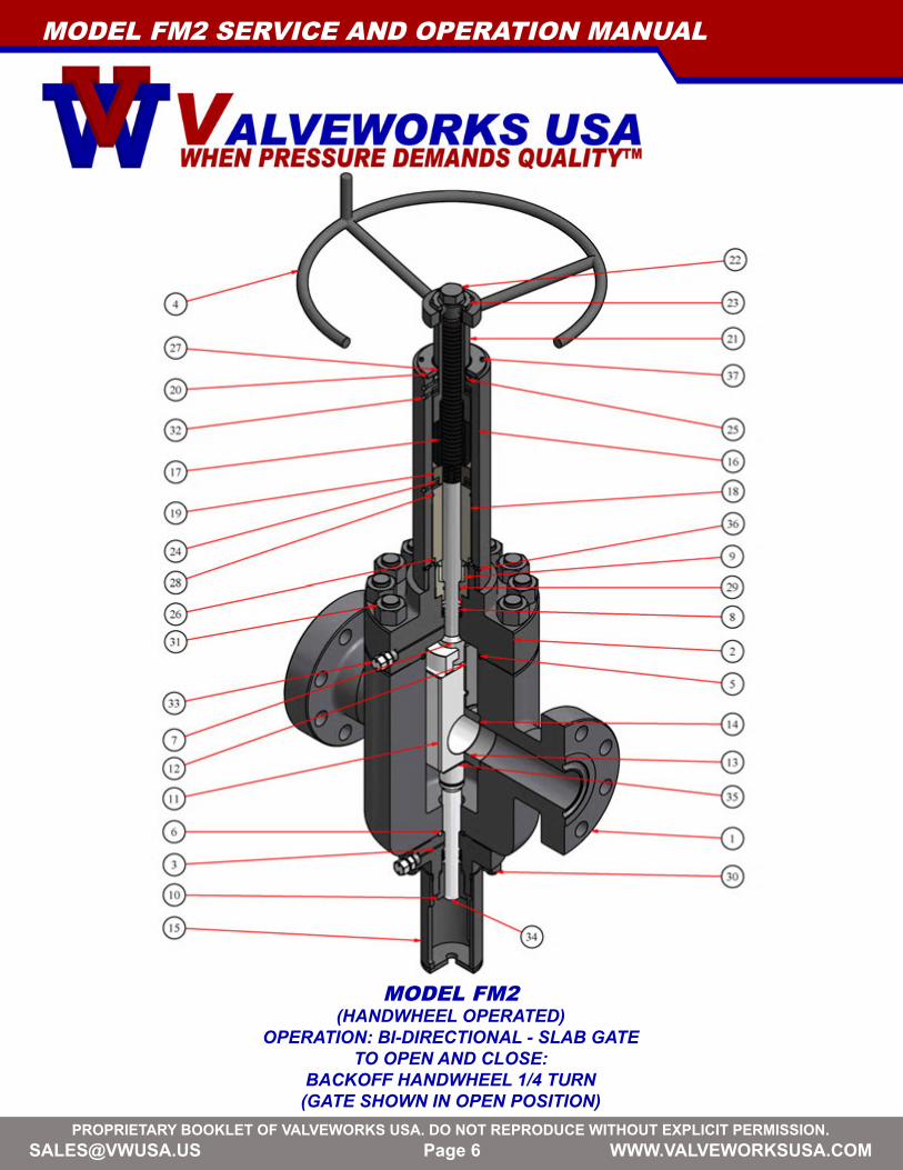
OPERATIONThe Valveworks USA Model FM2 gate valves are Ball Screw operated valves. The gate of the MODEL FM2 Valve is a one piece slab gate that uses two floating seats to generate a highly reliable seal. The slab gate eliminates the chance of trapping pressure within the body cavity which can cause pressure locking.
• Fully open the valve before installing or shipping. The sealing area of the gate, in the full open position, is protected by the body and is less likely to be damaged.
• Do not remove the molybdenum disulfide coating from internal parts. This coating serves as a lubricant and corrosion inhibitor.
• To hydrostatically test the valve body to full API test pressure, the valve must be in a partially open position. When testing the valve in the closed position (seat test) do not exceed the working pressure stamped on the valve identification plate.
• During storage always leave the valve in the fully opened or fully closed position. This will prevent damage to the sealing area of both the gate and seats.
• Always remove the valve from service before work is performed on the stem bearings.• When lubricating the body do not exceed the maximum API working pressure stamped on
the identification plate. • The valve should be fully closed or fully opened during lubrication of the body or seats. Seat
lubrication pressures should not exceed the maximum allowable API test pressure.
This method of operation will prevent damage to the sealing surfaces of the gate and seats, and will increase the life of the valve.
[email protected] BOOKLET OF VALVEWORKS USA. DO NOT REPRODUCE WITHOUT EXPLICIT PERMISSION.
Page 6
MODEL FM2 SERVICE AND OPERATION MANUAL
MODEL FM2(HANDWHEEL OPERATED)
OPERATION: BI-DIRECTIONAL - SLAB GATE TO OPEN AND CLOSE:
BACKOFF HANDWHEEL 1/4 TURN (GATE SHOWN IN OPEN POSITION)
[email protected] BOOKLET OF VALVEWORKS USA. DO NOT REPRODUCE WITHOUT EXPLICIT PERMISSION.
Page 7
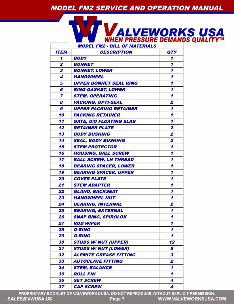
MODEL FM2 - BILL OF MATERIALSITEM DESCRIPTION QTY
1 BODY 12 BONNET 13 BONNET, LOWER 14 HANDWHEEL 15 UPPER BONNET SEAL RING 16 RING GASKET, LOWER 17 STEM, OPERATING 18 PACKING, OPTI-SEAL 29 UPPER PACKING RETAINER 1
10 PACKING RETAINER 111 GATE, D/O FLOATING SLAB 112 RETAINER PLATE 213 BODY BUSHING 214 SEAL, BODY BUSHING 215 STEM PROTECTOR 116 HOUSING, BALL SCREW 117 BALL SCREW, LH THREAD 118 BEARING SPACER, LOWER 119 BEARING SPACER, UPPER 120 COVER PLATE 121 STEM ADAPTER 122 GLAND, BACKSEAT 123 HANDWHEEL NUT 124 BEARING, INTERNAL 225 BEARING, EXTERNAL 126 SNAP RING, SPIROLOX 127 ROD WIPER 128 O-RING 129 O-RING 130 STUDS W/ NUT (UPPER) 1231 STUDS W/ NUT (LOWER) 832 ALEMITE GREASE FITTING 333 AUTOCLAVE FITTING 234 STEM, BALANCE 135 ROLL PIN 136 SET SCREW 437 CAP SCREW 4
MODEL FM2 SERVICE AND OPERATION MANUAL
[email protected] BOOKLET OF VALVEWORKS USA. DO NOT REPRODUCE WITHOUT EXPLICIT PERMISSION.
Page 8
MODEL FM2 SERVICE AND OPERATION MANUAL
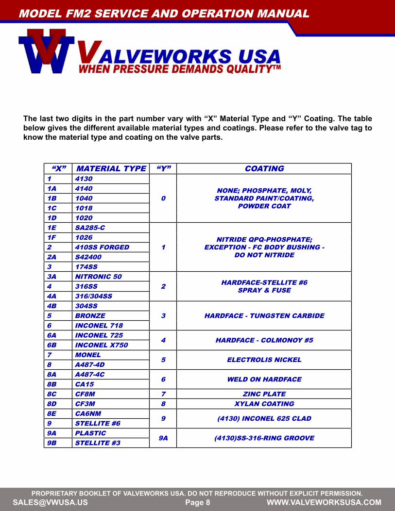
“X” MATERIAL TYPE “Y” COATING1 4130
0NONE; PHOSPHATE, MOLY,
STANDARD PAINT/COATING, POWDER COAT
1A 41401B 10401C 10181D 10201E SA285-C
1NITRIDE QPQ-PHOSPHATE;
EXCEPTION - FC BODY BUSHING - DO NOT NITRIDE
1F 10262 410SS FORGED2A S424003 174SS3A NITRONIC 50
2 HARDFACE-STELLITE #6 SPRAY & FUSE4 316SS
4A 316/304SS4B 304SS
3 HARDFACE - TUNGSTEN CARBIDE5 BRONZE6 INCONEL 7186A INCONEL 725
4 HARDFACE - COLMONOY #56B INCONEL X7507 MONEL
5 ELECTROLIS NICKEL8 A487-4D8A A487-4C
6 WELD ON HARDFACE8B CA158C CF8M 7 ZINC PLATE8D CF3M 8 XYLAN COATING8E CA6NM
9 (4130) INCONEL 625 CLAD9 STELLITE #69A PLASTIC
9A (4130)SS-316-RING GROOVE9B STELLITE #3
The last two digits in the part number vary with “X” Material Type and “Y” Coating. The table below gives the different available material types and coatings. Please refer to the valve tag to know the material type and coating on the valve parts.

[email protected] BOOKLET OF VALVEWORKS USA. DO NOT REPRODUCE WITHOUT EXPLICIT PERMISSION.
Page 9
MODEL FM2 SERVICE AND OPERATION MANUAL
DISASSEMBLING THE VALVE
1. (Horizontal Orientation)Unscrew and remove the
Handwheel Nut with a crescent wrench.
2. Remove the Handwheel. 3. Unscrew and remove Cover Plate Screws with an allen wrench.
4. Remove the Cover Plate.Note: Use a wire brush to clean paint
off the stem adapter.5. Unscrew and remove Set Screws
on the Ball Screw Housing.
7. Rotate handwheel clockwise while unscrewing the Ball Screw Housing
(counter-clockwise).
6. Replace the Handwheel.
8. Rotate the handwheel counter-clockwise to back up the Ball Screw
Housing enough to access the Spirolox Retainer Ring.
9. Remove the Handwheel.

[email protected] BOOKLET OF VALVEWORKS USA. DO NOT REPRODUCE WITHOUT EXPLICIT PERMISSION.
Page 10
MODEL FM2 SERVICE AND OPERATION MANUAL
10. Remove the Retainer Ring with a screwdriver. 11. Remove the Ball Screw Housing. 12. Remove the Roll Pin to
disengage the Ball Screw.
13. Remove the Ball Screw Assembly.
17. Remove the Upper Bonnet. 18. This gives access to the Bonnet Seal Ring, Gate, and Seats.
15. (Vertical Orientation)Unscrew and remove the
Packing Retainer.14. Remove the Bearing Sleeve and
Retainer Ring.
16. Unscrew and remove the Bonnet Nuts using a torque wrench.
[email protected] BOOKLET OF VALVEWORKS USA. DO NOT REPRODUCE WITHOUT EXPLICIT PERMISSION.
Page 11
MODEL FM2 SERVICE AND OPERATION MANUAL
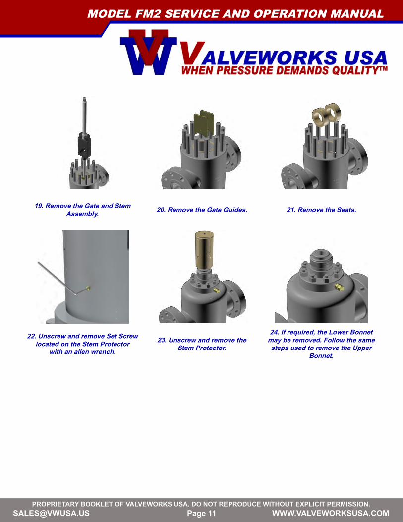
20. Remove the Gate Guides.19. Remove the Gate and Stem Assembly. 21. Remove the Seats.
24. If required, the Lower Bonnet may be removed. Follow the same steps used to remove the Upper
Bonnet.
22. Unscrew and remove Set Screw located on the Stem Protector
with an allen wrench.23. Unscrew and remove the
Stem Protector.
[email protected] BOOKLET OF VALVEWORKS USA. DO NOT REPRODUCE WITHOUT EXPLICIT PERMISSION.
Page 12
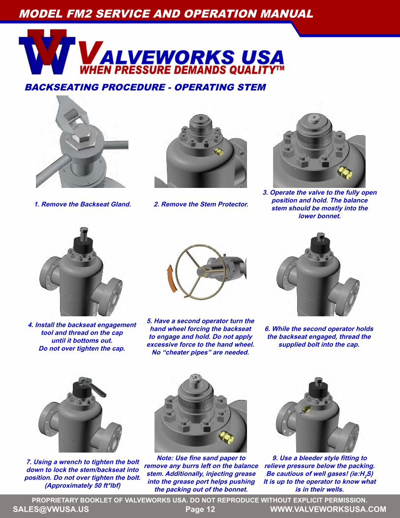
2. Remove the Stem Protector.1. Remove the Backseat Gland.3. Operate the valve to the fully open
position and hold. The balance stem should be mostly into the
lower bonnet.
5. Have a second operator turn the hand wheel forcing the backseat to engage and hold. Do not apply
excessive force to the hand wheel. No “cheater pipes” are needed.
4. Install the backseat engagement tool and thread on the cap
until it bottoms out. Do not over tighten the cap.
6. While the second operator holds the backseat engaged, thread the
supplied bolt into the cap.
BACKSEATING PROCEDURE - OPERATING STEM
7. Using a wrench to tighten the bolt down to lock the stem/backseat into
position. Do not over tighten the bolt. (Approximately 50 ft*lbf)
Note: Use fine sand paper to remove any burrs left on the balance stem. Additionally, injecting grease into the grease port helps pushing
the packing out of the bonnet.
9. Use a bleeder style fitting to relieve pressure below the packing.Be cautious of well gases! (ie:H2S)
It is up to the operator to know what is in their wells.
MODEL FM2 SERVICE AND OPERATION MANUAL
[email protected] BOOKLET OF VALVEWORKS USA. DO NOT REPRODUCE WITHOUT EXPLICIT PERMISSION.
Page 13
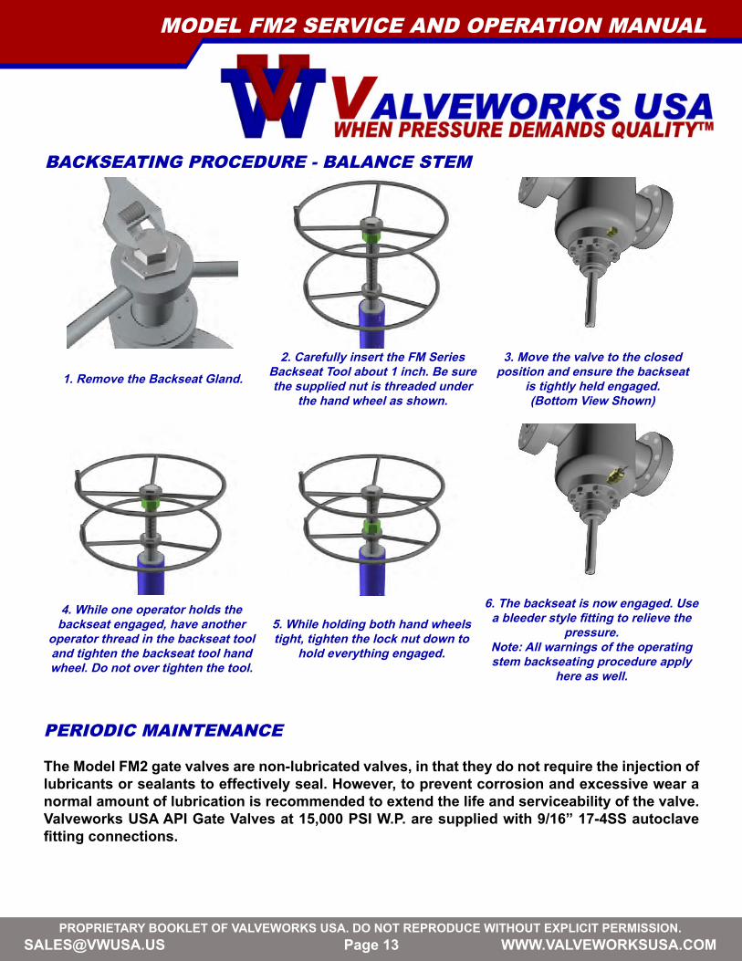
2. Carefully insert the FM Series Backseat Tool about 1 inch. Be sure the supplied nut is threaded under
the hand wheel as shown.1. Remove the Backseat Gland.
3. Move the valve to the closed position and ensure the backseat
is tightly held engaged. (Bottom View Shown)
5. While holding both hand wheels tight, tighten the lock nut down to
hold everything engaged.
4. While one operator holds the backseat engaged, have another
operator thread in the backseat tool and tighten the backseat tool hand wheel. Do not over tighten the tool.
6. The backseat is now engaged. Use a bleeder style fitting to relieve the
pressure. Note: All warnings of the operating stem backseating procedure apply
here as well.
BACKSEATING PROCEDURE - BALANCE STEM
PERIODIC MAINTENANCE
The Model FM2 gate valves are non-lubricated valves, in that they do not require the injection of lubricants or sealants to effectively seal. However, to prevent corrosion and excessive wear a normal amount of lubrication is recommended to extend the life and serviceability of the valve.Valveworks USA API Gate Valves at 15,000 PSI W.P. are supplied with 9/16” 17-4SS autoclave fitting connections.
MODEL FM2 SERVICE AND OPERATION MANUAL

[email protected] BOOKLET OF VALVEWORKS USA. DO NOT REPRODUCE WITHOUT EXPLICIT PERMISSION.
Page 14
MAINTENANCE TOOLS
To perform normal maintenance and lubrication, the following tools are recommended:
Grease pump with adapter and coupling Safety pressure releasing tool
BALL SCREW BEARING LUBRICATIONValveworks USA FM2 valves are equipped with alemite hydraulic type 1/8” NPT bonnet grease fittings. Ball Screw bearing lubrication is accomplished through this fitting using a standard type grease gun. Any good grade No. 3 grease is recommended for this lubrication. Ball screw bearings normally do not require great amounts of grease. If too much lubrication should occur, excess grease will flow around the stem to the atmosphere.
CAUTION: If bearings should need to be changed, the valve must be removed from service. During pressurized valve body lubrication, pressure applied to the valve body with the grease gun must not exceed the maximum working pressure of the valve being lubricated.
VENTING OR DRAINING A VALVEMost products contain a certain amount of water, line scale, sediment and other foreign matter which tend to accumulate in the valve body. A regular draining program will increase the life of a valve against damage caused by:
• Water freezing in the body cavity, causing damage to the body.• An accumulation of foreign matter in the lower part of the body that could prevent the valve
from fully closing; resulting in a throttling action that may cause inefficient sealing.• Foreign matter trapped in the body may become lodged between the sealing surfaces of the
gate and seats, resulting in scored or damaged sealed.• Venting a Model FM2 valve is a positive method of checking the sealing ability of the gate
and seats. If the body vents down to zero pressure with the valve in fully closed position, this is definite indication that sealing surfaces are in good condition.
MODEL FM2 SERVICE AND OPERATION MANUAL
[email protected] BOOKLET OF VALVEWORKS USA. DO NOT REPRODUCE WITHOUT EXPLICIT PERMISSION.
Page 15
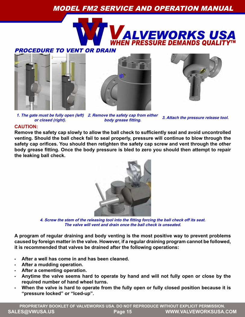
PROCEDURE TO VENT OR DRAIN
2. Remove the safety cap from either body grease fitting.
CAUTION: Remove the safety cap slowly to allow the ball check to sufficiently seal and avoid uncontrolled venting. Should the ball check fail to seal properly, pressure will continue to blow through the safety cap orifices. You should then retighten the safety cap screw and vent through the other body grease fitting. Once the body pressure is bled to zero you should then attempt to repair the leaking ball check.
3. Attach the pressure release tool.
4. Screw the stem of the releasing tool into the fitting forcing the ball check off its seat. The valve will vent and drain once the ball check is unseated.
A program of regular draining and body venting is the most positive way to prevent problems caused by foreign matter in the valve. However, if a regular draining program cannot be followed, it is recommended that valves be drained after the following operations:
• After a well has come in and has been cleaned.• After a mudding operation.• After a cementing operation.• Anytime the valve seems hard to operate by hand and will not fully open or close by the
required number of hand wheel turns.• When the valve is hard to operate from the fully open or fully closed position because it is
“pressure locked” or “Iced-up”.
1. The gate must be fully open (left) or closed (right).
MODEL FM2 SERVICE AND OPERATION MANUAL
[email protected] BOOKLET OF VALVEWORKS USA. DO NOT REPRODUCE WITHOUT EXPLICIT PERMISSION.
Page 16
“ICED-UP” is a condition caused by a restriction in the flow or a differential in the pressure of gas flow at high pressure, which produces extremely low temperatures.
These restrictions or differentials in pressure may be caused by throttling through a valve.This happens by leakage of a closed valve or leakage through the stem packing. Valvesin service on gas containing hydrates or in fresh water service, which are exposed to lowexternal temperatures can also get “iced-up”. In this case it is advisable to inject alcohol orglycol into the valve body through the drain fitting to combat these conditions.
The same procedures are used for injecting alcohol or glycol as are used for valve bodylubrication. Do not operate the valve immediately after injecting as these fluids should beretained in the body to perform the Antifreeze effect.
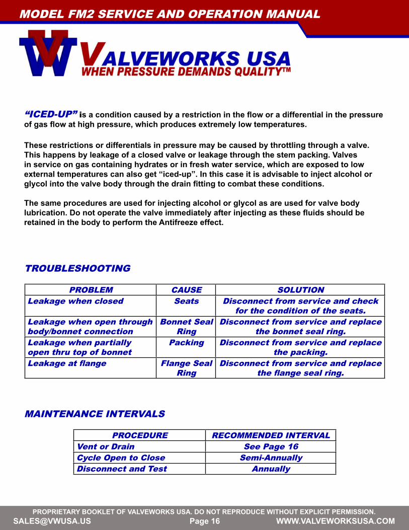
TROUBLESHOOTING
PROBLEM CAUSE SOLUTIONLeakage when closed Seats Disconnect from service and check
for the condition of the seats.Leakage when open through body/bonnet connection
Bonnet Seal Ring
Disconnect from service and replace the bonnet seal ring.
Leakage when partially open thru top of bonnet
Packing Disconnect from service and replace the packing.
Leakage at flange Flange Seal Ring
Disconnect from service and replace the flange seal ring.
MAINTENANCE INTERVALS
PROCEDURE RECOMMENDED INTERVALVent or Drain See Page 16Cycle Open to Close Semi-AnnuallyDisconnect and Test Annually
MODEL FM2 SERVICE AND OPERATION MANUAL

[email protected] BOOKLET OF VALVEWORKS USA. DO NOT REPRODUCE WITHOUT EXPLICIT PERMISSION.
Page 17
1. Grease and insert a ring joint into the body flange.
Note: Refer to the end of the manual for studded outlet to prepare for testing.
5. Tighten the hex nuts on the test flange side with a torque wrench
until they are tight.
4. Screw each hex nut on the vacant side of a stud until all of the studs have a nut on the test flange and
the valve flange.6. A finished flange shown.
8. Remove the grease fitting cap from one test flange and attach a
pressure release tool.7. Repeat steps 1-5 for the opposite
flange.9. Remove the grease fitting cap from the opposite test flange and
attach the flow line.
TEST PROCEDURE
2. Be sure that the test flange has a tightened grease fitting, all of its studs, and a nut on each with all of the nuts on the grease fitting side.
3. Align the test flange studs with the body flange holes. Then, push the
test flanges, its studs, and their hex nuts onto the body flange.
MODEL FM2 SERVICE AND OPERATION MANUAL
[email protected] BOOKLET OF VALVEWORKS USA. DO NOT REPRODUCE WITHOUT EXPLICIT PERMISSION.
Page 18
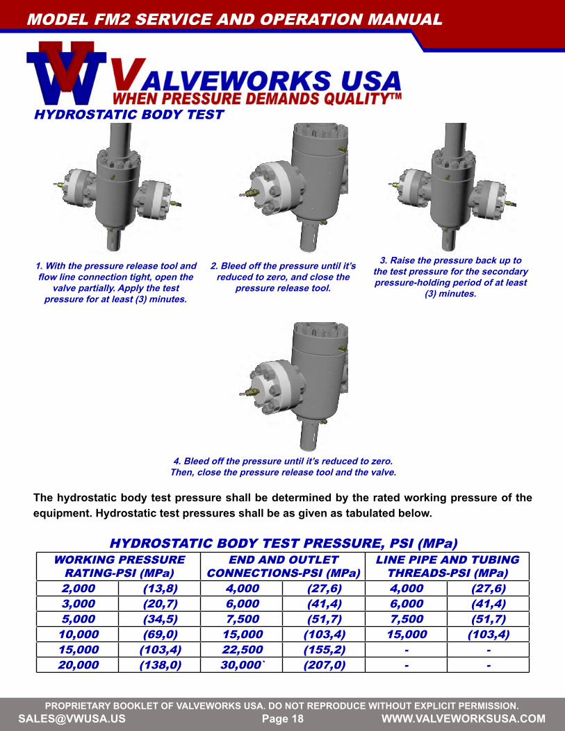
1. With the pressure release tool and flow line connection tight, open the
valve partially. Apply the test pressure for at least (3) minutes.
4. Bleed off the pressure until it’s reduced to zero. Then, close the pressure release tool and the valve.
HYDROSTATIC BODY TEST
2. Bleed off the pressure until it’s reduced to zero, and close the
pressure release tool.
3. Raise the pressure back up to the test pressure for the secondary pressure-holding period of at least
(3) minutes.
The hydrostatic body test pressure shall be determined by the rated working pressure of the equipment. Hydrostatic test pressures shall be as given as tabulated below.
HYDROSTATIC BODY TEST PRESSURE, PSI (MPa)WORKING PRESSURE
RATING-PSI (MPa)END AND OUTLET
CONNECTIONS-PSI (MPa)LINE PIPE AND TUBING
THREADS-PSI (MPa)2,000 (13,8) 4,000 (27,6) 4,000 (27,6)3,000 (20,7) 6,000 (41,4) 6,000 (41,4)5,000 (34,5) 7,500 (51,7) 7,500 (51,7)
10,000 (69,0) 15,000 (103,4) 15,000 (103,4)15,000 (103,4) 22,500 (155,2) - -20,000 (138,0) 30,000` (207,0) - -
MODEL FM2 SERVICE AND OPERATION MANUAL
[email protected] BOOKLET OF VALVEWORKS USA. DO NOT REPRODUCE WITHOUT EXPLICIT PERMISSION.
Page 19
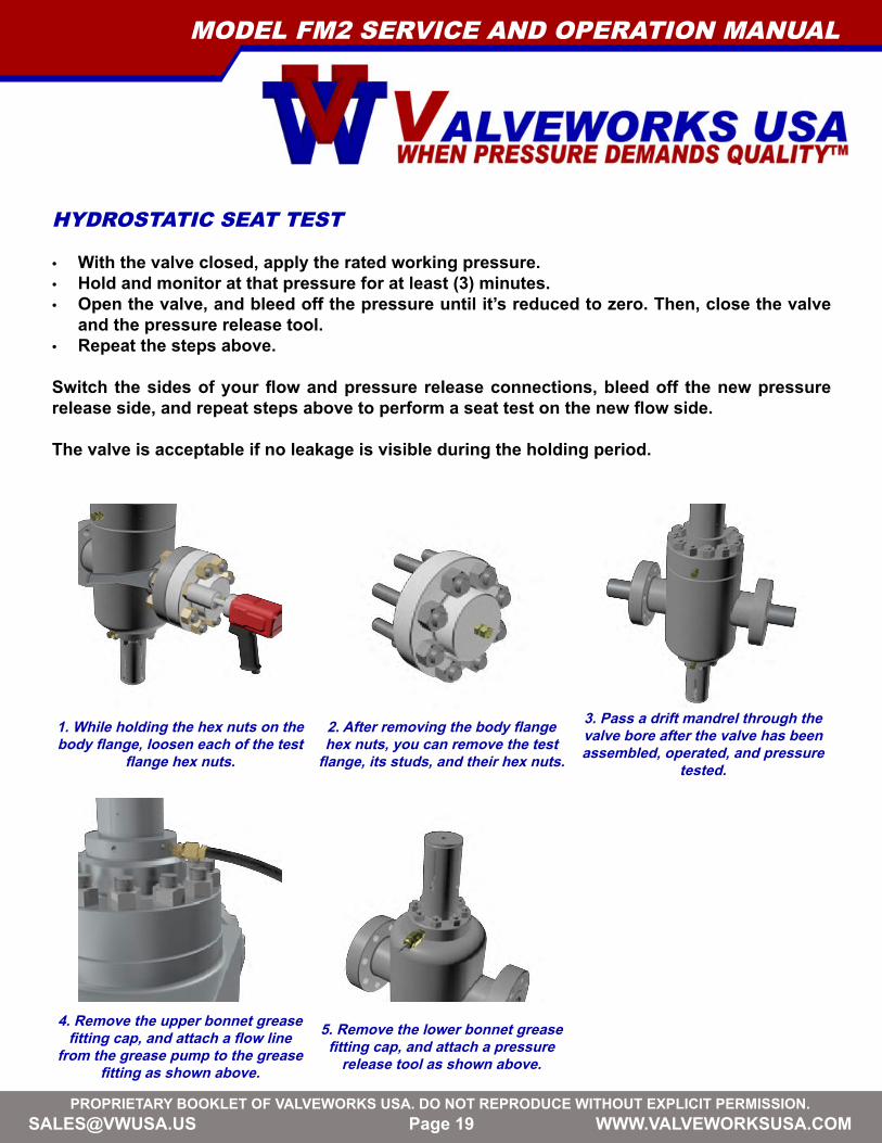
2. After removing the body flange hex nuts, you can remove the test
flange, its studs, and their hex nuts.
1. While holding the hex nuts on the body flange, loosen each of the test
flange hex nuts.
3. Pass a drift mandrel through the valve bore after the valve has been assembled, operated, and pressure
tested.
5. Remove the lower bonnet grease fitting cap, and attach a pressure
release tool as shown above.
4. Remove the upper bonnet grease fitting cap, and attach a flow line
from the grease pump to the grease fitting as shown above.
HYDROSTATIC SEAT TEST
• With the valve closed, apply the rated working pressure.• Hold and monitor at that pressure for at least (3) minutes.• Open the valve, and bleed off the pressure until it’s reduced to zero. Then, close the valve
and the pressure release tool.• Repeat the steps above.
Switch the sides of your flow and pressure release connections, bleed off the new pressure release side, and repeat steps above to perform a seat test on the new flow side.
The valve is acceptable if no leakage is visible during the holding period.
MODEL FM2 SERVICE AND OPERATION MANUAL

[email protected] BOOKLET OF VALVEWORKS USA. DO NOT REPRODUCE WITHOUT EXPLICIT PERMISSION.
Page 20
2. Be sure the lower bonnet grease fitting cap is on and tight.
1. Be sure the upper bonnet grease fitting cap is on and tight.
3. Be sure the Alemite fittings are on and tight.
4. Be sure the Hand wheel Nut is tight.
VISUAL INSPECTION
4. Torque the service flange hex nuts with a certified
torque gun until they are tight.3. Screw a hex nut on both sides of each stud by hand.
5. Be sure the Alemite fittings are on and tight.
2. Align the service flange holes with the body flange holes. Push a stud through each aligned
hole until there is a stud through each hole. 1. Grease and insert ring joint into the valve flange.
FIELD HOOK-UP INSTRUCTIONS5. The gate must be fully open (left) or closed (right).
MODEL FM2 SERVICE AND OPERATION MANUAL

[email protected] BOOKLET OF VALVEWORKS USA. DO NOT REPRODUCE WITHOUT EXPLICIT PERMISSION.
Page 21
MODEL FM2 SERVICE AND OPERATION MANUAL
A
B
C
D
E
NT
WT
FLANGE TO FLANGE
VALVE BORE SIZE
BORE CENTERLINE TO BOTTOM
BORE CENTERLINE TO TOP
HANDWHEEL DIAMETER
NUMBER OF TURNS
APPROXIMATE WEIGHT
DIMENSION TABLE KEY
SIZE WP (PSI) A B C D E NT WT4 1/16 15K 29 4 1/16 25 3/4 54 1/4 28 9 5/8 2050
FLANGED GATE VALVES
[email protected] BOOKLET OF VALVEWORKS USA. DO NOT REPRODUCE WITHOUT EXPLICIT PERMISSION.
Page 22 [email protected] BOOKLET OF VALVEWORKS USA. DO NOT REPRODUCE WITHOUT EXPLICIT PERMISSION.
1650 SWAN LAKE ROADBOSSIER CITY, LA USA 71111
PHONE 318-425-0266FAX 318-425-0934TOLL FREE 888-425-0266EMAIL [email protected] WWW.VALVEWORKSUSA.COM