proposed earthen constructed wetland crep wetland
TRANSCRIPT
IOWA MINNESOTA WISCONSIN
Factual Geotechnical Report:
Proposed Earthen Constructed Wetland CREP Wetland Flo941603B Section 3 – T95N – R16W St. Charles Township, Floyd County, Iowa CVT# 13244.18.IAM
Prepared for:
Mr. Nathan Anderson, PE WHKS & Co.
Certification:
I hereby certify that this report was prepared by me or
under my direct supervision, and that I am a duly
Licensed Professional Engineer under the laws of the
State of Iowa.
Matthew J. Reisdorfer, PE
Geotechnical Engineer
License Number 22234
Date: July 19, 2018

M i n n e s o t a I o w a W i s c o n s i n
TABLE OF CONTENTS
A. Introduction .......................................................................................................................2
A.1. Purpose ................................................................................................................................... 2
A.2. Scope ...................................................................................................................................... 2
A.3. Boring Locations and Elevation ................................................................................................. 2
A.4. Geologic Background ............................................................................................................... 3
B. Subsurface Data .................................................................................................................3
B.1. Stratification ............................................................................................................................ 3
B.2. Penetration Test Results........................................................................................................... 4
B.3. Groundwater Data ................................................................................................................... 5
C. Level of Care .......................................................................................................................5
Appendix .................................................................................................................................6
Soil Boring Location Sketch
Log of Boring # 2, 4-8
Legend to Soil Description

CREP Wetland Flo941603B July 19, 2018
Project: 13244.18.IAM Page - 2
M i n n e s o t a I o w a W i s c o n s i n
Chosen Valley Testing, Inc. Geotechnical Engineering and Testing • 421 North Georgia Avenue • Mason City, IA 50401 • Telephone (641) 201-1050 • [email protected]
Mr. Nathan Anderson, PE July 19, 2018
WHKS & Co
2905 South Broadway
Rochester, MN 55904
Re: Proposal for Factual Geotechnical Evaluation
Proposed Earthen Constructed Wetland
CREP Wetland Flo941603B
Section 3 – T95N – R16W
St. Charles Township, Floyd County, Iowa
CVT Proposal Number: 13244.18.IAM
Dear Mr. Anderson:
This factual report was prepared to assist planning for the proposed earthen constructed wetland in St. Charles
Township, Floyd County, Iowa. Our services were authorized by Mr. Nathan Anderson of WHKS.
A. Introduction
The intent of this report is to present our results to the client in the same logical sequence that led us to arrive
at the opinions and recommendations expressed. Since our services must often be completed before the design,
assumptions are sometimes needed to prepare a proper evaluation and to analyze the data. A complete and
thorough review of this entire document, including the assumptions and the appendices, should be undertaken
immediately upon receipt.
A.1. Purpose
This factual report was prepared to assist planning for the proposed earthen constructed wetland in St. Charles
Township in Floyd County, Iowa. Our services were authorized by Mr. Nathan Anderson of WHKS.
A.2. Scope
To obtain data for analysis, our services included a total of 6 penetration test borings, drilled to depths of 16 to
41 feet below the surface. Our engineering scope consisted of providing a factual discussion of the soils and
materials encountered during our exploration.
A.3. Boring Locations and Elevation
The desired borings locations were indicated to Chosen Valley Testing on site plans provided by the client.
The Boring Location Sketch in the Appendix shows the approximate locations drilled. Elevations were
estimated using the Iowa DNR LiDAR software. These elevations should be considered approximate.

CREP Wetland Flo941603B July 19, 2018
Project: 13244.18.IAM Page - 3
M i n n e s o t a I o w a W i s c o n s i n
A.4. Geologic Background
A geotechnical report is based on subsurface data collected for the specific structure or problem. Available
geologic data from the region can help interpretation of the data and is briefly summarized in this section.
Area geologic maps indicate that the natural upper soils are primarily glacial deposits of sand, silt and clay
mixtures. Bedrock is expected to be within 100 feet from the surface and consist of dolomite and limestone of
the Cedar Valley Group
B. Subsurface Data
Methods: All of the borings were performed using penetration test procedures (Method of Test D1586 of the
American Society for Testing and Materials). This procedure allows for the extraction of intact soil specimen
from deep in the ground. With this method, a hollow-stem auger is drilled to the desired sampling depth. A 2-
inch OD sampling tube is then screwed onto the end of a sampling rod, inserted through the hole in the auger's
tip, and then driven into the soil with a 140-pound hammer dropped repeatedly from a height of 30 inches above
the sampling rod. The sampler is driven 18-inches into the soil, unless the material is too hard. The samples are
generally taken at 2½ to 5-foot intervals. The core of soil obtained is classified and logged by the driller and a
representative portion is then sealed in a jar and delivered to the soils engineer for review.
B.1. Stratification
At the surface, the southeast boring (Boring B-7) encountered peat, to a depth of about 5 ½ feet. The remaining
borings encountered topsoil at the surface, to depths of about 1 to 2 feet.
Clayey sand was encountered below the topsoil layer in the southwest boring (Boring B-6) to a depth of about
5 feet. In the northeast boring (Boring B-8) clean sand was encountered to depths of about 7 ½ feet.
Glacial till consisting of sandy lean clay was encountered below the clayey sand, clean sand, peat and topsoil
layers, where sands were not encountered. The borings terminated in the glacial clays at depths of about 16 to
41 feet below the surface.
The following simplified cross-section summarizes the boring data. For more detailed information, please refer
to the Log of Boring sheets in the Appendix.

CREP Wetland Flo941603B July 19, 2018
Project: 13244.18.IAM Page - 4
M i n n e s o t a I o w a W i s c o n s i n
1015
1020
1025
1030
1035
1040
1045
1050
1055
1060
1065
1070
1075
B-2 B-4 B-5 B-6 B-7 B-8
Approximate Depth (Feet)
Boring Number
Topsoil
Peat
Sand
Clayey Sand
Glacial Clay
Below Boring
B.2. Penetration Test Results
The number of blows needed for the hammer to advance the penetration test sampler is an indicator of soil
characteristics. The number of blows to advance the sampler 1 foot is called the penetration resistance or “N”-
value. The results tend to be more meaningful for natural mineral soils, than for fill soils. In fill soils, compaction
tests are more meaningful.
Penetration resistance values (N-values) of 3 to 77 Blows per Foot (BPF) were recorded in the glacial clays,
indicating they were very soft to hard. A penetration value of 5 BPF was recorded in the clayey sand, indicating
it was loose.
A key to the descriptors used to qualify the relative density of soil (such as soft, stiff, loose, and dense) can be
found on the Legend to Soil Description in the Appendix.
A pocket penetrometer was used to provide additional data on the compressive strength of the cohesive soils.
The glacial clays returned values of ¾ to greater than 4 ½ tons per square foot (tsf).

CREP Wetland Flo941603B July 19, 2018
Project: 13244.18.IAM Page - 5
M i n n e s o t a I o w a W i s c o n s i n
B.3. Groundwater Data
During the drilling operation, the drillers may note the presence of moisture on the sampling instrument, in the
cuttings, or within the borehole. These observations are recorded on the boring logs. The water level may vary
with weather; time of year and other factors and the presence or absence of water during the drilling is subject
to interpretation and is not always conclusive.
Water was observed in most of the borings during drilling, at depths of about 4 to 30 ½ feet below the surface.
These water levels correspond to elevations of about 1026 ½ to 1058 ½. Elevated moisture contents were also
recorded in most of the near surface glacial clays samples. This is likely due to water bearing seams of sand
becoming trapped within the less permeable clays. Groundwater levels at the site are expected to fluctuate
seasonally with nearby creeks and rivers, as well as with local weather patterns.
C. Level of Care
The services provided for this project have been conducted in a manner consistent with that level of care and
skill ordinarily exercised by members of the profession currently practicing in this area, under similar budget
and time constraints. This is our professional responsibility. No other warranty, expressed or implied, is made.

CREP Wetland Flo941603B July 19, 2018
Project: 13244.18.IAM Page - 6
M i n n e s o t a I o w a W i s c o n s i n
Appendix
Soil Boring Location Sketch
Log of Boring: 2, 4-8
Legend to Soil Description

N
Soil Boring Location Sketch Proposed Earthen Constructed Wetland
CREP Wetland Flo941603B
Section 3 – T95N – R16W
St. Charles Township, Floyd County, Iowa
CVT Proposal Number: 13244.18.IAM
C Chosen Valley Testing, Inc.
V T
Legend Boring Locations Benchmark

16.04759618.0
4759483.0
4759348.0
Elev. (ft)
4759390.0
4759418.0
16.0
1071.0
4759511.0
521961.0
Borehole
521964.0
521964.0
1061.0
1057.0 41.0
41.0
Eastng (m)
521931
522227
521931
522227CVT 13244.18.IAM (FLOYD COUNTY WETLANDS).GPJ FNC AB GWGN01.GDT 7/19/18
521964.0
1056.0
1060.0
522194.0
522171.0
16.0
Northing (m)
4759395
4759582
4759395
4759582
DISTANCES (m):
Beginning
Ending
VIEWING ANGLES (degrees):
Horizontal
Vertical
Elevation (ft)
Floyd County Wetland
Packard Ave, between 250th and 260th Sts
0
350
Easting (m)
Distance Along Baseline (m)
1066.0
1,015
1,020
1,070
1,020
1,075
1,015
1,0251,025
1,035
1,040
1,045
1,050
1,055
1,060
1,055
1,065
1,075
1,030
1,060
1,050
100 15050 200
1,045
0
1,040
300
1,070
1,035
1,065
350
16.0
1,030
250
Jul 18
Northing (m)
PROJECT # DATE PLATE
SUBSURFACE FENCE DIAGRAM
B-2
B-4
B-5
B-6
B-7
B-8
13244.18.IAM
0 50 100 150 200 250 300 350
Position
Left, Front
Right, Front
Left, Back
Right, Back
Depth (ft)
0.0
0.0
15
20
12
11
3
23
25
13
17
4
B-2
14
B-6
2
6
20
B-5
5
16
B-7
15
14
B-4
5
20
15
21
26
21
35
77
B-8

Slightly Organic SANDY LEAN CLAY(Topsoil)
1059.3
1052.8
1044.3
B-2 page 1 of 1
1.0
LEAN CLAY with SAND trace gravel, dark gray,wet, rather stiff.
(Glacial Till)
CVT STANDARD 13244.18.IAM (FLOYD COUNTY W
ETLANDS).GPJ LOG A GNNN06.GDT 7/19/18
3
11
1216.0
7.5
CLOL
PP = 0.75 tsf, MC = 19.0%
PP = 2.25 tsf
PP = 2.5 tsf, MC = 18.6%
End of boringBoring sealed upon completion
Tests and NotesDepthElev.
SANDY LEAN CLAY brown, wet, soft.(Glacial Till)
USCSSymbol
DATE: 6/27/2018
Description of Materials(ASTM D 2487/2488)
WL
PROJECT:
13244.18.IAM
BORING:
0.0
B-2
1060.3
L O G O F B O R I N GCHOSEN VALLEY TESTING
SCALE: 1" = 6'
BPF
13244.18.IAM
Design Phase Geotechnical Evaluations
Floyd County Wetland
Packard Ave, between 250th and 260th Sts
Charles City, Iowa
See attached sketchLOCATION:

1.2Slightly Organic SANDY LEAN CLAY
(Topsoil)
PP = 1.0 tsf, MC = 23.0%
PP = 2.25 tsf
PP = 1.5 tsf
CVT STANDARD 13244.18.IAM (FLOYD COUNTY W
ETLANDS).GPJ LOG A GNNN06.GDT 7/19/18
PP = 2.75 tsf
MC = 15.4%
7.5
41.0
1055.2
1048.9
1015.4
PP > 4.5 tsf
CLOL
PP = 3.5 tsf, MC = 15.4%
4
17
13
25
23
14
20
15
SANDY LEAN CLAY seams of sand, dark gray,very wet, rather soft.
(Glacial Till)
BPF
13244.18.IAM
Design Phase Geotechnical Evaluations
Floyd County Wetland
Packard Ave, between 250th and 260th Sts
Charles City, Iowa
Description of Materials(ASTM D 2487/2488)
LOCATION:
USCSSymbol
Tests and NotesDepth
SCALE: 1" = 6'
Water encountered at about15 feet during drilling.PP = 1.25 tsf, MC = 23.2%
WLElev.
DATE: 6/27/2018
B-4 page 1 of 1
LEAN CLAY with SAND trace gravel, dark gray,wet, stiff to very stiff.
(Glacial Till)
Very wet below 12.5'
Wet below 22.5'
Brown below 37.5'
See attached sketch
0.0
L O G O F B O R I N G
BORING:PROJECT:
1056.4
13244.18.IAM
B-4
CHOSEN VALLEY TESTING
1.0 Slightly Organic SANDY LEAN CLAY(Topsoil)
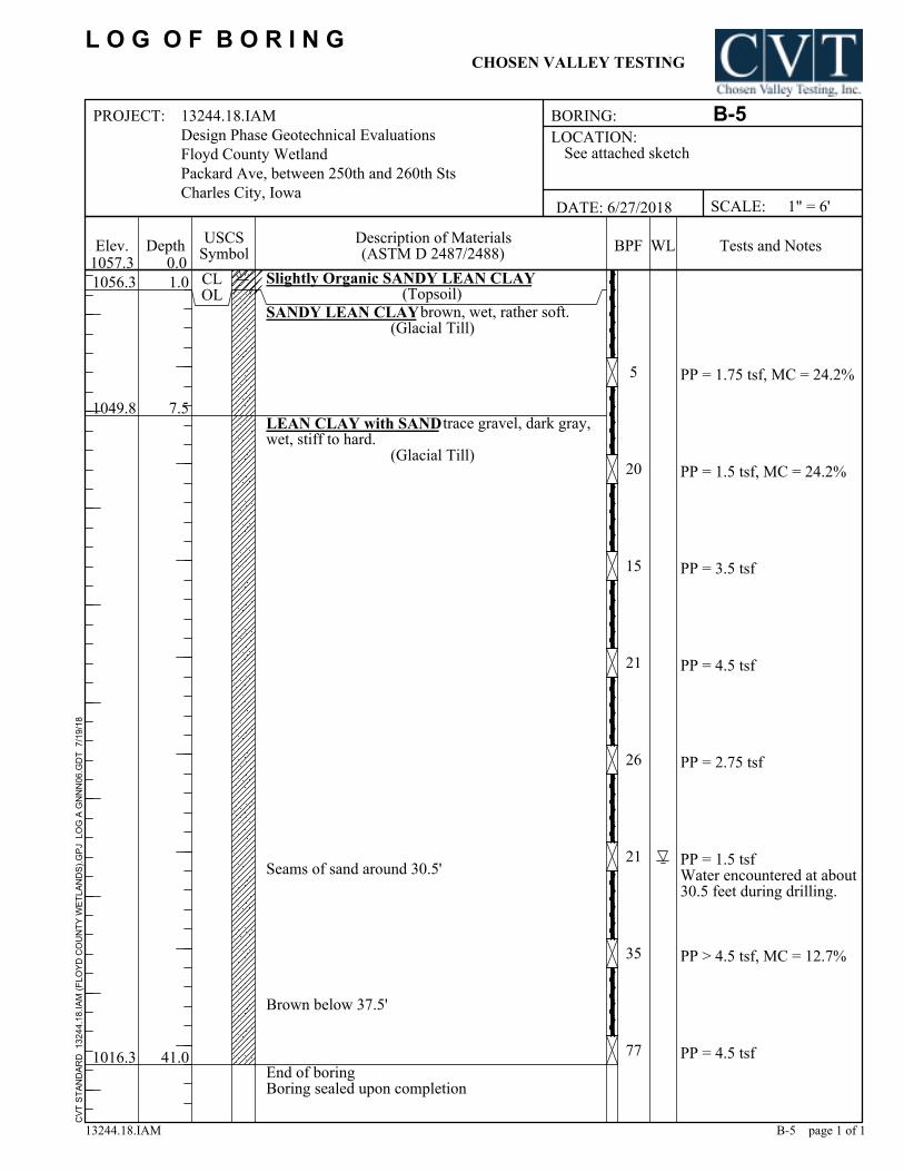
PP = 1.75 tsf, MC = 24.2%
PP = 1.5 tsf, MC = 24.2%
PP = 4.5 tsf
CVT STANDARD 13244.18.IAM (FLOYD COUNTY W
ETLANDS).GPJ LOG A GNNN06.GDT 7/19/18
PP = 1.5 tsfWater encountered at about30.5 feet during drilling.
PP = 4.5 tsf
7.5
41.0
1056.3
1049.8
1016.3
PP > 4.5 tsf, MC = 12.7%
CLOL
PP = 2.75 tsf
5
20
15
21
26
21
35
77
SANDY LEAN CLAY brown, wet, rather soft.(Glacial Till)
BPF
13244.18.IAM
Design Phase Geotechnical Evaluations
Floyd County Wetland
Packard Ave, between 250th and 260th Sts
Charles City, Iowa
Description of Materials(ASTM D 2487/2488)
LOCATION:
USCSSymbol
Tests and NotesDepth
SCALE: 1" = 6'
PP = 3.5 tsf
WLElev.
DATE: 6/27/2018
B-5 page 1 of 1
LEAN CLAY with SAND trace gravel, dark gray,wet, stiff to hard.
(Glacial Till)
Seams of sand around 30.5'
Brown below 37.5'
End of boringBoring sealed upon completion
See attached sketch
0.0
L O G O F B O R I N G
BORING:PROJECT:
1057.3
13244.18.IAM
B-5
CHOSEN VALLEY TESTING

Slightly Organic LEAN CLAY(Topsoil)
1070.0
1066.2
1055.2
1.2
LEAN CLAY with SAND gray, wet, raterh soft tostiff.
(Glacial Till)
CVT STANDARD 13244.18.IAM (FLOYD COUNTY W
ETLANDS).GPJ LOG A GNNN06.GDT 7/19/18
End of boringBoring sealed upon completion
CLOL
5
16
16.0
5.0
SC
PP = 1.5 tsf
PP = 3.5 tsf, MC = 17.5%
PP = 3.5 tsf
Trace gravel below 7.5'Dark gray below 7.5'
Tests and NotesDepth
B-6 page 1 of 1
CLAYEY SAND fine to medium grained, brown,moist, loose.
(Glacial Till)
USCSSymbol
DATE: 6/27/2018
Description of Materials(ASTM D 2487/2488)
WL
B-6
13244.18.IAM
0.0Elev.
LOCATION:
BORING:
BPF
See attached sketch
13244.18.IAM
Design Phase Geotechnical Evaluations
Floyd County Wetland
Packard Ave, between 250th and 260th Sts
Charles City, Iowa
PROJECT:
SCALE: 1" = 6'
CHOSEN VALLEY TESTING
L O G O F B O R I N G
1071.2

BORING:
1060.1
1049.6
PEAT(Swamp Deposit)
LEAN CLAY with SAND trace gravel, dark gray,wet, medium to very stiff.
(Glacial Till)
End of boringBoring sealed upon completion
16.0
CVT STANDARD 13244.18.IAM (FLOYD COUNTY W
ETLANDS).GPJ LOG A GNNN06.GDT 7/19/18
B-7 page 1 of 1
0.0
Seams of sand around 15'
2
6
No sample return
Water encountered at about7 feet during drilling.
PP = 1.5 tsf, MC = 22.0%
PP = 1.5 tsf
5.5
20
DATE: 6/27/2018
Depth
B-7
Tests and NotesElev.Description of Materials(ASTM D 2487/2488)
WL
L O G O F B O R I N G
13244.18.IAM
1065.6
CHOSEN VALLEY TESTING
SCALE: 1" = 6'
BPF
13244.18.IAM
Design Phase Geotechnical Evaluations
Floyd County Wetland
Packard Ave, between 250th and 260th Sts
Charles City, Iowa
See attached sketchLOCATION:
USCSSymbol
PROJECT:

Slightly Organic LEAN CLAY(Topsoil)
1059.0
1053.5
1045.0
2.0
LEAN CLAY with SAND trace gravel, dark gray,wet, very stiff.
(Glacial Till)
CVT STANDARD 13244.18.IAM (FLOYD COUNTY W
ETLANDS).GPJ LOG A GNNN06.GDT 7/19/18
CLOL
15
1416.0
7.5
SP
Water encountered at about4 feet during drilling.
PP = 1.25 tsf, MC = 20.5%
PP = 3.5 tsf, MC = 16.6%
End of boringBoring sealed upon completion
Tests and NotesDepth
B-8 page 1 of 1
POORLY GRADED SAND trace gravel, seams oflean clay, fine to medium grained, brown, wet towater bearing.
(Alluvium)
USCSSymbol
DATE: 6/27/2018
Description of Materials(ASTM D 2487/2488)
WL
B-8
13244.18.IAM
0.0Elev.
LOCATION:
BORING:
BPF
See attached sketch
13244.18.IAM
Design Phase Geotechnical Evaluations
Floyd County Wetland
Packard Ave, between 250th and 260th Sts
Charles City, Iowa
PROJECT:
SCALE: 1" = 6'
CHOSEN VALLEY TESTING
L O G O F B O R I N G
1061.0

GROUPSYMBOL
SOIL GROUP NAMES & LEGEND
PRIMARILY ORGANIC MATTER, DARK IN COLOR, AND ORGANIC ODOR
BLOWS/FOOT* CONSISTENCY
SAMPLE TYPES
Job No. 13244.18.IAM
GRAVELS WITH FINES
>12% FINES
2.0 - 4.0OVER 4.0
TERM
TraceWith
Modifier
0.50 - 1.0
1.0 - 2.0
0 - 0.250.25 - 0.50
GW
GP
GM
GC
SW
SP
SM
SC
CL
ML
OL
CH
MH
OH
PT
CLEAN GRAVELS
<5% FINES
WATER LEVEL (WITH TIME OF)
MEASUREMENT
0 - 4
4 - 10
10 - 30
30 - 50
OVER 50
LIQUID LIMIT (%)
CH
0
10
20
30
40
50
60
70
80
PLASTICITY INDEX (%)
SIZE
< 12 in.3 in. - 12 in.
#4 sieve to 3 in.#200 sieve to #4 sievePassing #200 sieve
TERM
BoulderCobbleGravelSand
Silt or Clay
SAND & GRAVEL
CRITERIA FOR ASSIGNING SOIL GROUP NAMES
-
-
-
MC
OC
CN
DD
PP
RV
SA
P200
>50% OF COARSEFRACTION PASSESON NO 4. SIEVE
RELATIVE DENSITY
(RECORDED AS BLOWS / 0.5 FT)
CL
SILT & CLAY
NUMBER OF BLOWS OF 140 LB HAMMER FALLING 30 INCHES TO DRIVE A 2 INCH O.D.
(1-3/8 INCH I.D.) SPLIT-BARREL SAMPLER THE LAST 12 INCHES OF AN 18-INCH DRIVE
(ASTM-1586 STANDARD PENETRATION TEST).
*
BLOWS/FOOT*
WELL-GRADED GRAVEL
POORLY-GRADED GRAVEL
SILTY GRAVEL
CLAYEY GRAVEL
WELL-GRADED SAND
POORLY-GRADED SAND
SILTY SAND
CLAYEY SAND
LEAN CLAY
SILT
ORGANIC CLAY OR SILT
FAT CLAY
ELASTIC SILT
ORGANIC CLAY OR SILT
PENETRATION RESISTANCE
Hollow Stem
LEGEND TO SOIL
DESCRIPTIONS
FINES CLASSIFY AS ML OR CL
FINES CLASSIFY AS CL OR CH
PI>7 AND PLOTS>"A" LINE
PI>4 AND PLOTS<"A" LINE
LL (oven dried)/LL (not dried)<0.75
PI PLOTS >"A" LINE
PI PLOTS <"A" LINE
LL (oven dried)/LL (not dried)<0.75
COMPRESSIVE
STRENGTH (TSF)
Chosen Valley Testing
-
CLEAN SANDS
<5% FINES
SANDS AND FINES
>12% FINES
INORGANIC
MOISTURE CONTENT
ORGANIC CONTENT
CONSOLIDATION
DRY DENSITY
POCKET PENETROMETER
R-VALUE
SIEVE ANALYSIS
% PASSING #200 SIEVE
LIQUID LIMIT
PLASTISITY INDEX
SWELL TEST
Unconsolidated Undrained triaxial
LL
PI
SW
UU
PERCENT
< 55 - 12> 12
Relative Proportions of Fines
Standard Penetration Test
VERY SOFTSOFTRATHER SOFTMEDIUMRATHER STIFFSTIFFVERY STIFFHARD
UNIFIED SOIL CLASSIFICATION (ASTM D-2487/2488)
ML
MH
-
-
-
-
-
-
-
-
TEST SYMBOLS
PERCENT
< 1515 - 29> 30
ORGANIC
Relative Proportions of Sand and Gravel
0 - 12 - 34 - 56 - 89 - 1213 - 1617 - 30OVER 30
INORGANIC
TERM
TraceWith
Modifier
Grain Size Terminology
Cu>4 AND 1<Cc<3
Cu>4 AND 1>Cc>3
FINES CLASSIFY AS ML OR CL
FINES CLASSIFY AS CL OR CH
ORGANIC
VERY LOOSE
LOOSE
MEDIUM DENSE
DENSE
VERY DENSE
GRAVELS
0 10 20 30 40 50 60 70 80 90 100 110 120
MATERIALTYPES
Cu>6 AND 1<Cc<3
Cu>6 AND 1>Cc>3
CVT 13244.18.IAM (FLOYD COUNTY W
ETLANDS).GPJ 7/19/18
PEAT
SANDS
SILTS AND CLAYS
LIQUID LIMIT>50
SILTS AND CLAYS
LIQUID LIMIT<50
>50% OF COARSEFRACTION RETAINED
ON NO 4. SIEVE
HIGHLY ORGANIC SOILS
COARSE-G
RAINED SOILS
>50% RETAINED ON
NO. 200 SIEVE
FINE-G
RAINED SOILS
>50% PASSES
NO. 200 SIEVE
PLASTICITY CHART
"A" LINE
CL-ML