proposed corrective measures plan and design, pg&e · pdf file1.2 site background ......
TRANSCRIPT

D r a f t
Proposed Corrective Measures Plan and Design,
PG&E Shell Pond and Carbon Black Area,
Bay Point, California
Prepared for
Pacific Gas and Electric Company
April 2011


Draft Proposed Corrective Measures Plan and Design
PG&E Shell Pond and Carbon Black Area
April 2011
Prepared for: Pacific Gas and Electric Company
San Ramon, CA
Prepared by: CH2M HILL
155 Grand Avenue, Suite 800 Oakland, CA 94612
Signature: _______________________________________ Date: ________________ Name: Diane Sarmiento, P.E. Title: Civil Engineer CH2M HILL Signature: _______________________________________ Date: ________________ Name: Elizabeth Dodge Title: Vice President
CH2M HILL


ES113010003017BAO\111010009 v
Contents
Acronyms and Abbreviations .................................................................................................. ix
1.0 Introduction .................................................................................................................. 1-1 1.1 Purpose and Objectives .................................................................................. 1-1 1.2 Site Background ............................................................................................... 1-1 1.3 Corrective Measure Implementation Supporting Studies ......................... 1-2 1.4 Corrective Measures Implementation Overview ........................................ 1-2
2.0 Previous Studies and Characterization ................................................................... 2-1 2.1 PG&E Shell Pond Water ................................................................................. 2-1 2.2 Former Wastewater Discharge Ditch ............................................................ 2-1 2.3 PG&E Shell Pond Non-Native Material ....................................................... 2-1
2.3.1 Field Studies ........................................................................................ 2-1 2.3.2 PG&E Shell Pond Non-Native Material Treatability Tests .......... 2-3 2.3.3 Carbon Black Area .............................................................................. 2-6
2.4 Regulatory Permitting Requirements ........................................................... 2-6 2.5 Environmental Protection Measures ............................................................ 2-7 2.6 Sustainability Options .................................................................................... 2-8
3.0 Corrective Measures Goals ........................................................................................ 3-1 3.1 PG&E Shell Pond and Former Wastewater Discharge Ditch .................... 3-1
3.1.1 Planned or Potential Future Use ...................................................... 3-1 3.1.2 Remediation Goals ............................................................................. 3-1 3.1.3 Final Remediation Status ................................................................... 3-4
3.2 Carbon Black Area ........................................................................................... 3-4 3.2.1 Planned or Potential Future Use ...................................................... 3-4 3.2.2 Remediation Goals ............................................................................. 3-4 3.2.3 Final Remediation Status ................................................................... 3-5
4.0 Corrective Measures Construction Implementation ............................................ 4-1 4.1 Phase 1—Access Road and Material Handling Area Construction ......... 4-1
4.1.1 Mobilization ........................................................................................ 4-1 4.1.2 Temporary Access Road and Bridge Construction ....................... 4-1 4.1.3 Material Handling and Construction Staging Areas ..................... 4-2
4.2 Phase 2— Removal of Material from PG&E Shell Pond and the Former Wastewater Discharge Ditch, and Carbon Black Area Revegetation ...... 4-2 4.2.1 Removal of Non-Native Material in PG&E Shell Pond ................ 4-2 4.2.2 Former Wastewater Discharge Ditch Soil Removal ...................... 4-4 4.2.3 Water Management ............................................................................ 4-5 4.2.4 Confirmation Sampling and Analysis ............................................. 4-5 4.2.5 Transportation and Disposal ............................................................ 4-5 4.2.6 Carbon Black Area Fill and Seeding ................................................ 4-6
4.3 Phase 3—PG&E Shell Pond Levee Breach ................................................... 4-7

PROPOSED CORRECTIVE MEASURES PLAN AND DESIGN CONTENTS PG&E SHELL POND AND CARBON BLACK AREA
vi ES113010003017BAO\111010009
5.0 Site Management ......................................................................................................... 5-1 5.1 Site Access ......................................................................................................... 5-1 5.2 Site Security ...................................................................................................... 5-1 5.3 Traffic Control .................................................................................................. 5-1 5.4 Biological Resources ........................................................................................ 5-1 5.5 Cultural Resources ........................................................................................... 5-1 5.6 Air Quality, Odors, and Dust ......................................................................... 5-2 5.7 Health and Safety ............................................................................................. 5-2 5.8 Public Participation.......................................................................................... 5-2
6.0 Post-Construction Monitoring Plan ......................................................................... 6-1 6.1 Overview ........................................................................................................... 6-1 6.2 Monitoring Plan Components ........................................................................ 6-1
6.2.1 Marsh Evolution .................................................................................. 6-1 6.2.2 Water Quality ...................................................................................... 6-2 6.2.3 Success Criteria ................................................................................... 6-2
7.0 Code, Regulations, Standards, and References ...................................................... 7-1
8.0 Project Organization .................................................................................................... 8-1
9.0 Project Schedule ........................................................................................................... 9-1
10.0 References ................................................................................................................... 10-1
Figures 1-1 Site Location and Vicinity Map 2-1 Contour Map of Estimated Thickness of Non-Native Material 4-1 Proposed Project Elements 4-2 Site Plan 4-3 Wetland and Unvegetated Portions of Carbon Black Area 4-4 Conceptual Sections Proposed Levee Breach 9-1 Shell Pond Corrective Action Implementation Schedule
Tables
2-1 Hazardous Waste Evaluation: Volatile and Semivolatile Organics - Shell Pond Sediments
2-2 Hazardous Waste Evaluation: Metals - PG&E Shell Pond Sediments 2-3 PG&E Shell Pond Environmental Protection Measures 3-1 Screening Values for Chemicals of Potential Ecological Concern in Sediment 3-2 Approved Remediation Goals 4-1 Corrective Measures Elements 4-2 Plans in Support of the PG&E Shell Pond Corrective Measures Implementation 9-1 PG&E Shell Pond Restoration Schedule

CORRECTIVE MEASURES IMPLEMENTATION PLAN PG&E SHELL POND AND CARBON BLACK AREA CONTENTS
ES113010003017BAO\111010009 vii
Appendices A Plans and Specifications
A1 Phase 1, Temporary Access Road and Bridge Plans and Specifications A2 Phase 1-3, 30% Design Drawings
B Waste and Water Management Plan C Sampling and Analysis Plan D Traffic Control and Waste Transportation Plan E Environmental Compliance Monitoring Plan F Air Quality Management Plan G Health and Safety Plan


ES113010003017BAO\111010009 ix
Acronyms and Abbreviations
µg/L micrograms per liter
APN Assessor’s Parcel Number
BAAQMD Bay Area Air Quality Management District
BCDC Bay Conservation and Development Commission
BTEX benzene, toluene, ethylbenzene, and xylenes
CA Consent Agreement
CBA Carbon Black Area
CDFG California Department of Fish and Game
CEQA California Environment Quality Act
COPC constituent of potential concern
Dexter/Hysol Hysol division of the Dexter Corporation
DO dissolved oxygen
DTSC California Department of Toxic Substances Control
EcoPRG Ecological Preliminary Remediation Goal
GHG greenhouse gas
HDPE high-density polyethylene
mg/kg milligrams per kilogram
mg/L milligrams per liter
MTBE methyl tert-butyl ether
NNM non-native material
NPDES National Pollutant Discharge Elimination System
PAH polycyclic aromatic hydrocarbon
PCMPD Proposed Corrective Measures Plan and Design
PG&E Pacific Gas and Electric Company
ppm parts per million
project proposed PG&E Shell Pond remedy
RCRA Resource Conservation and Recovery Act
RWQCB San Francisco Bay Area Regional Water Quality Control Board
SOx sulfur oxide
STLC soluble threshold limit concentration
SVOC semivolatile organic compound
TCLP toxicity characteristic leaching procedure
TPH total petroleum hydrocarbons
PROPOSED CORRECTIVE MEASURES PLAN AND DESIGN CONTENTS PG&E SHELL POND AND CARBON BLACK AREA
x ES113010003017BAO\111010009
TTLC total threshold limit concentration
USACE U.S. Army Corps of Engineers
VOC volatile organic compound
ES113010003017BAO\111010009 1-1
1.0 Introduction
1.1 Purpose and Objectives This Draft Proposed Corrective Measures Plan and Design (PCMPD) for the Pacific Gas and Electric Company (PG&E) Shell Pond and Carbon Black Area (CBA) describes the activities and presents preliminary (30 percent) design drawings (Appendix A) to implement the remedy described in the Corrective Measures Study (CH2M HILL, 2010a), which was approved by California Department of Toxic Substances Control (DTSC) in November 2010. The proposed PG&E Shell Pond remedy (the project) is a modification to the corrective action described in the Corrective Action Consent Agreement (CA) P2 03/04/006 (DTSC, 2004), which was determined by DTSC to be no longer viable or sustainable.
1.2 Site Background The PG&E Shell Pond is a 73-acre former wastewater pond, and the CBA is an approximate 22-acre upland area. Both are located within a 292-acre parcel (Assessor’s Parcel Number [APN] 098-260-001) in Bay Point, California, as shown on Figure 1-1 (all figures are located at the end of this document). The PG&E Shell Pond and CBA were created in the late 1930s and 1940s, when levees were constructed to create a pond to receive wastewater discharges from a commercial ammonia plant owned by the Shell Oil Products Company and the Hysol division of the Dexter Corporation (Dexter/Hysol), an adhesives manufacturer, both located south of the PG&E Shell Pond. PG&E purchased the pond and surrounding land in 1973, and discharges from the plant to the pond were terminated in 1980 (Woodward Clyde Consultants, 1986). Since 1980, PG&E has conducted investigations, monitoring, and remedial activities at the site. The remainder of the parcel and surrounding PG&E-owned property to the east and west are primarily estuarine wetlands adjacent to Suisun Bay in the Sacramento-San Joaquin Delta.
In 2000, PG&E and DTSC entered into the current CA that prescribed a remedy that consisted of maintaining a water cap over the pond for odor control and circulating water to maintain a relatively stable salinity in the pond (DTSC, 2000; 2004). To comply with the CA, water was pumped from the east slough into the pond and discharged via a weir structure in the northwestern corner of the PG&E Shell Pond under a National Pollutant Discharge Elimination System (NPDES) permit. Difficulty in meeting the NPDES discharge limits (pH, dissolved oxygen [DO], and mercury) resulted in PG&E re-evaluating the corrective action described in the CA.
The CA (Section 21.0) allows for modification of the agreement by mutual agreement between DTSC and PG&E. In accordance with this provision, and to achieve a long-term, sustainable remedy for the site, a Corrective Measures Study was prepared by CH2M HILL on behalf of PG&E (CH2M HILL, 2010a) and approved by DTSC.

PROPOSED CORRECTIVE MEASURES PLAN AND DESIGN 1.0 INTRODUCTION PG&E SHELL POND AND CARBON BLACK AREA
1-2 ES113010003017BAO\111010009
1.3 Corrective Measure Implementation Supporting Studies Numerous studies, surveys, and activities were conducted to prepare for implementation of the approved corrective measure. These supporting studies include the following:
Investigation of material in the PG&E Shell Pond and former wastewater discharge ditch (ENTRIX, 2009a; CH2M HILL, 2010b);
Bench and pilot tests (CH2M HILL, 2010c); and
Wetlands Delineation, Draft Restoration Plan and various biological assessments performed in support of the U.S. Army Corps of Engineers (USACE) 404 Nationwide Permit Application and San Francisco Bay Area Regional Water Quality Control Board (RWQCB) Water Quality Certification permit application.
The results of the investigation and bench and pilot tests are summarized in Section 2.0 of this document.
1.4 Corrective Measures Implementation Overview This project includes the following:
Construction of a temporary road and bridge to provide safer access to the PG&E Shell Pond area during construction, by using a controlled railroad crossing.
Removal of non-native material (NNM) that exceeds approved remediation goals within the PG&E Shell Pond using both hydraulic removal and mechanical excavation (in areas where hydraulic removal is not feasible). NNM includes materials deposited in the pond with former wastewater discharges and mixed underlying native material that contains constituents above the approved remediation goals.
Construction of a temporary Material Handling Area for dewatering the NNM that is removed hydraulically from the PG&E Shell Pond.
Removal of soil that exceeds approved remediation goals in the portion of the former wastewater discharge ditch on PG&E property.
Offsite transportation and disposal of soil and NNM to a permitted disposal facility.
Fill placement on the upland unvegetated areas of the CBA and reseeding of the unvegetated upland and wetland areas of the CBA. Fill will be obtained from the PG&E-owned parcel west of PG&E Shell Pond.
Removal of approximately 82 feet of the eastern levee of the PG&E Shell Pond to provide tidal connection via east slough/channel and to restore the pond area to a self-sustaining mixed tidal habitat.
This project has the following benefits:
Restores the PG&E Shell Pond to a self-sustaining tidal habitat that will enhance environmental quality, control salinity, and eliminate odors from the NNM.
Eliminates the high level of maintenance necessary to maintain the water cap.

PROPOSED CORRECTIVE MEASURES PLAN AND DESIGN PG&E SHELL POND AND CARBON BLACK AREA 1.0 INTRODUCTION
ES113010003017BAO\111010009 1-3
Eliminates NPDES discharges and the need for the associated permits, maintenance, and monitoring activities.
Enhances vegetative cover on the CBA.


ES113010003017BAO\111010009 2-1
2.0 Previous Studies and Characterization
Corrective measures developed for the PG&E Shell Pond site are based on past characterization studies, an evaluation of corrective measure alternatives, and bench and pilot testing. Additional studies performed as part of environmental permit requirements, sustainability considerations, and schedule were considered in developing this implementation plan. The following sections summarize information used as the basis for the remediation construction.
2.1 PG&E Shell Pond Water The depth of water in the pond varies seasonally and with maintenance activities. In general, the water in the pond is shallow, varying from 0 to 3 feet deep.
Constituents of potential concern (COPCs), including polycyclic aromatic hydrocarbons (PAHs) and metals found in the NNM material, are present in the pond surface water at low concentrations (Brown and Caldwell, 1983; Woodward Clyde Consultants, 1986). Sampling in 2009 (ENTRIX, 2009a) concluded that pond water samples contained some metals and PAHs at greater concentrations than in water samples collected from the adjacent eastern slough.
Based on results of NPDES discharge sampling, the pond water has generally met discharge criteria, with some exceptions. For NPDES monitoring in 2007, these exceptions included pH greater than the discharge limit of 8.5; DO lower than 5 milligrams per liter (mg/L); and mercury mass greater than the average monthly limit.
2.2 Former Wastewater Discharge Ditch The wastewater discharge ditch historically conveyed wastewater from the Shell Oil Products Company to the PG&E Shell Pond. Soil samples from the wastewater ditch contain metals above background concentrations and PAHs above screening values at depths of up to 1.5 feet below ground surface (ENTRIX, 2009a). Mercury, selenium, molybdenum, lead, and several other metals were detected above background concentrations at levels similar to those found in the NNM in the pond (ENTRIX, 2009a).
2.3 PG&E Shell Pond Non-Native Material 2.3.1 Field Studies Field investigations and laboratory testing of samples provided thickness and analytical results for NNM within the PG&E Shell Pond (CH2M HILL, 2010b; ENTRIX, 2009a). Bathymetric mapping and field odor suppression testing were also performed during CH2M HILL’s field investigation. The results of these investigations indicate the following:
The bottom of the pond is generally flat with approximately 75 percent of the pond having an elevation between 5.5 and 4.5 feet above mean sea level.

PROPOSED CORRECTIVE MEASURES PLAN AND DESIGN 2.0 PREVIOUS STUDIES AND CHARACTERIZATION PG&E SHELL POND AND CARBON BLACK AREA
2-2 ES113010003017BAO\111010009
Analytical results indicated that elevated concentrations of PAHs, metals (primarily copper, lead, mercury, and molybdenum), total petroleum hydrocarbons (TPH)-diesel, and TPH-motor oil are present within the NNM. Concentrations of these contaminants are orders of magnitude lower in the underlying native media and are generally less than or equal to the low-range Ecological Preliminary Remediation Goals (EcoPRGs) for constituents with screening criteria.
Results of the sampling and analysis did not indicate any elevated concentrations of PAHs within the underlying native material.
The thickness of the NNM is variable and ranges from approximately 0.5 to 2.5 feet within the PG&E Shell Pond, as shown on Figure 2-1.
The NNM is generally a distinct layer overlying native terrestrial clay, Younger Bay Mud, or organic soil, with visual evidence that this material has not penetrated more than 0.5 foot into the underlying materials.
The NNM generally overlies stiff terrestrial clay in the southern 25 percent of the pond and soft Young Bay Mud and organic soil (peat) in the northern 75 percent of the pond.
The estimated volume of NNM containing constituents exceeding target remediation goals (see Section 3.2.1) is 180,000 cubic yards. It is expected that for this volume of material, up to 240,000 cubic yards may be removed because of the variability in the NNM distribution and the overall accuracy of removal equipment (within 0.5 foot).
Field odor suppressant testing indicated that the product, SL-6000, performed the best of three odor suppressants tested, receiving favorable results at all three dilution ratios tested. EM.1Waste Treatment performed moderately well, and Ecosorb606 yielded poor results.
On the basis of these findings, mechanical and hydraulic removal methods were selected as the most appropriate construction methods to remove NNM from the pond.
Mechanical removal was selected for the south end of the pond for the following reasons:
It has a higher elevation and is generally dry most of the year.
The exposed dry material does not exhibit strong odors.
It is unlikely that the water level in the pond could be raised sufficiently to flood this area with a minimum 18 inches of water.
The underlying native material is stiff and accessible to low-pressure excavation equipment potentially with the use of crane mats.
Hydraulic removal was selected for the majority of the pond for the following reasons:
Maintenance of the water cover will minimize odors.
Hydraulic removal will take less time than trying to mechanically excavate the entire pond.

PROPOSED CORRECTIVE MEASURES PLAN AND DESIGN PG&E SHELL POND AND CARBON BLACK AREA 2.0 PREVIOUS STUDIES AND CHARACTERIZATION
ES113010003017BAO\111010009 2-3
The soft, native organic soil (peat) and bay mud that underlies the NNM makes equipment access (both for removal and loading) extremely difficult even for low-pressure tire equipment.
2.3.2 PG&E Shell Pond Non-Native Material Treatability Tests Bench and pilot tests were performed for the following reasons:
To evaluate polymers and dosages for efficient dewatering of the hydraulically removed material
To evaluate the quality of filtrate and general observations associated with use of geotextile tubes
To evaluate potential amendments to NNM to stabilize material for improved equipment access or as necessary for landfill disposal
To assess the implementability of mechanical excavation and hydraulic removal methods
To evaluate odor management alternatives
Bench and pilot testing (CH2M HILL, 2010c) resulted in the conclusions discussed below that pertain to mechanical and hydraulic excavation of the PG&E Shell Pond.
Bench Testing For mechanical bench testing, jar samples were prepared and evaluated for amendment with portland cement and Enviroblend CS. For each amendment type, mixtures of amendment and NNM were prepared at the following three dosages: 2 percent, 4 percent, and 8 percent (by volume). Samples were tested for strength and paint filter test properties.
For hydraulic testing, NNM was mixed with pond water to achieve a 5 percent solids solution. Two anionic polymers, Ciba Magnafloc 155 (Ciba Corporation, Tarrytown, NY) and TAG 1102 (Amber Group LLC, Irvine, CA), were evaluated for flocculation jar testing in addition to a control sample. Based on the results of the jar testing, TAG 1102 appears to be the most effective polymer for flocculation of the NNM in the pond. Optimum concentrations of TAG 1102 are expected to range from 6.0 to 7.5 mg/L, depending on the percent solids in the slurry. After completion of the jar testing, dewatering bag tests were performed to evaluate the dewatering capabilities of the NNM both with and without the selected polymer flocculent. Two tests were performed: one with a dosage of 7.5 parts per million (ppm) solution of the polymer TAG 1102 (Treated) and the other without any polymer addition (Control).
Pilot Testing
Mechanical Excavation Pilot Test Mechanical pilot testing involved field testing cells and amendment additions. These included the following:
1. Control cell: 20- by-20-foot area, ~6 to 9 inches of NNM
2. Portland Type II-V cement cell:

PROPOSED CORRECTIVE MEASURES PLAN AND DESIGN 2.0 PREVIOUS STUDIES AND CHARACTERIZATION PG&E SHELL POND AND CARBON BLACK AREA
2-4 ES113010003017BAO\111010009
a. 1% cement: 10- by-20-foot area, ~12 inches of NNM (average) b. 3% cement: 10- by-10-foot area, ~12 inches of NNM (average) c. 6% cement: 10- by-10-foot area, ~12 inches of NNM (average)
3. Enviroblend CS cell: 2% Enviroblend CS, 37- by-10-foot area, ~18 inches of NNM (average)
4. Enviroblend 93HR cell:
a. 2% Enviroblend 93HR: 15- by-14-foot area, ~18 inches of NNM (average) b. 6% Enviroblend 93HR: 15- by-14-foot area, ~18 inches of NNM (average)
Enviroblend CS and Enviroblend 93HR are mixtures of magnesium oxide and other chemicals such as magnesium hydroxide in varying concentrations. Enviroblend 93HR is a finer grained material than Enviroblend CS. Portland cement was the most effective amendment for stabilization of the mechanically excavated material during the pilot testing. Based on the results of the paint filter test and visual observation, it is anticipated that up to 1 percent by volume portland cement is sufficient to provide adequate stabilization for transport and disposal of the excavated material. In some areas, it is likely that no amendment will be needed.
The use of the excavator was an effective method for adding and mixing the amendments. During the pilot testing, the amendment was readily mixed into the NNM and appeared to be well distributed throughout the pilot test cells. The addition of any of the three amendments to the pond materials did not result in an increase in the pH of either the pond water or the pore water in the area adjacent to the treated cells (CH2M HILL, 2010c).
Hydraulic Removal Pilot Test Hydraulic pilot testing included removing NNM from the PG&E Shell Pond using a pontoon boat equipped with a 15-horsepower Toyota electric submersible pump with a 4-inch-diameter flexible discharge hose. The discharge, a slurry of pond water and NNM, was conveyed approximately 1,350 feet to the polymer mix area and geotube at the southern end of the pond. At the polymer mix area, the discharge hose was connected to a mixing manifold, where an anionic polymer, TAG 1102, was added to the slurry. Concentrations of the TAG 1102 ranged from 6.0 to 7.5 mg/L of TAG 1102 depending upon the percent solids in the slurry. The amended slurry was piped into an approximate 20-cubic-yard-capacity geotextile tube contained in a high-density polyethylene (HDPE)-lined and bermed area within the south end of the PG&E Shell Pond. Geotextile tubes appear to be an efficient and effective means to filter and dewater the slurry so that the NNM can be disposed of offsite. After approximately 2 days there was little or no water draining from the geotube, and within 1 week the material was sufficiently dewatered for offsite disposal without the addition of stabilizing amendment. The dewatering period can be expected to increase during full-scale operations based on the larger size of the geotextile tubes, the longer travel path for water in the NNM, and reduced permeability of the dredged material over time.
The water quality of the geotube filtrate indicates some water quality parameters exceed San Francisco Bay Basin Plan criteria (RWQCB, 2007). Aquatic LC50 toxicity tests performed on the geotextile tube filtrate indicate 95 percent survival of tested estuarine fish. The filtrate is expected to be acceptable for return to the pond during hydraulic removal, but further

PROPOSED CORRECTIVE MEASURES PLAN AND DESIGN PG&E SHELL POND AND CARBON BLACK AREA 2.0 PREVIOUS STUDIES AND CHARACTERIZATION
ES113010003017BAO\111010009 2-5
evaluation of post-removal pond water quality will be required before the release of pond water to the adjacent slough. Preliminary review of filtrate water quality compared to San Francisco Bay Basin Plan (RWQCB, 2007) water quality objectives indicates that before discharge to the slough, water in the PG&E Shell Pond may require treatment for petroleum hydrocarbons and several metals. Plans for testing filtrate and pond water during and after removal of NNM are contained in Appendices B and C.
Non-Native Material Classification During the pilot study, the NNM in the pond was characterized to determine appropriate disposal options. The characterization included collecting composite samples and analyzing those samples for contaminants including metals, PAHs, limited VOCs, and TPH. Previous investigations in the pond indicated that SVOCs (other than PAHs), VOCs, and pesticides were either not detectable or present at very low concentrations. All analytical results for VOCs, SVOCs, and pesticides with a regulatory limit for California hazardous waste and RCRA hazardous waste were non-detect (refer to Table 2-1; all tables are located at the end of this document.) As a result, the composite samples collected during the pilot study were not analyzed for pesticides or the full suite of SVOCs and VOCs.
The analytical results from the pilot study composite samples were compared to both RCRA hazardous waste criteria and to California hazardous waste criteria. RCRA hazardous waste designation is based on toxicity characteristic leaching procedure (TCLP) analyses. California hazardous waste criteria are based on both total threshold limit concentration (TTLC) and soluble threshold limit concentration (STLC) analyses. The following procedure was followed for the characterization of the NNM:
1. All composite samples were analyzed for Title 22 metals. In addition, the NNM from the mechanical excavation area (cement composite) and the hydraulic removal area (geotube) were analyzed for TPH and PAHs. Benzene, toluene, ethylbenzene, and xylenes (collectively referred to as BTEX) and methyl tert-butyl ether (MTBE) tests were also performed for the NNM from the mechanical removal area based on the relatively limited material disturbance associated with mechanical excavation. No BTEX or MTBE was detected, and PAHs do not have regulatory thresholds for hazardous waste classification.
2. Analytical results for metals were compared to TTLC regulatory thresholds for California hazardous waste. All results were well below the regulatory threshold for classifying the material as a hazardous waste (see Table 2-2).
3. Analytical results for metals were compared to the STLC and TCLP trigger levels. With the exception of chromium and lead, all composite sample results were below regulatory trigger levels for STLC and TCLP analyses. As shown in Table 2-2, nickel and copper concentrations in discrete samples did exceed STLC trigger levels, but average concentrations for the discrete samples, as well as analyses performed on samples composited from the discrete samples, were less than half of the trigger level concentrations for both nickel and copper.
4. STLC and TCLP analyses were performed for analytes exceeding trigger levels in the composite samples collected during the pilot study. As shown in Table 2-2, no STLC or TCLP thresholds were exceeded. Because no STLC or TCLP analyses were performed for

PROPOSED CORRECTIVE MEASURES PLAN AND DESIGN 2.0 PREVIOUS STUDIES AND CHARACTERIZATION PG&E SHELL POND AND CARBON BLACK AREA
2-6 ES113010003017BAO\111010009
samples collected during the previous sediment sampling event, a comparison of the average results for discrete samples and the average and maximum results for composite samples from that event were compared to the data collected during the pilot study. According to the analytical data collected to date, the NNM in the PG&E Shell Pond is non-hazardous.
Odor Management Although NNM in the PG&E Shell Pond has exhibited odors when exposed during sampling and during dry-weather periods, odors generated during the pilot studies were generally mild and did not require odor suppressant. The odor suppressant SL-6000 was tested using a misting system installed downwind of the pilot test area, and was found to be effective in suppressing the odors generated during the pilot test.
2.3.3 Carbon Black Area The CBA was the location of the Shell Oil Products Company’s first wastewater treatment pond. The results of investigations in 1995 and 1996 (Pacific Environmental Group, 1998) indicated that the COPCs were PAHs, benzene, total recoverable petroleum hydrocarbons, and some metals. Interim corrective measures in 1997 included the excavation of the tar-like materials and material with higher levels of total recoverable petroleum hydrocarbons, lead, beryllium, and benzene in nine isolated locations. Sampling following excavation of material in the CBA indicated that lower levels of benzene, total recoverable petroleum hydrocarbons, and beryllium remained (Pacific Environmental Group, 1998).
Early risk assessment sampling of COPCs at depths between 4 and 7 feet, including Title 22 metals, total recoverable petroleum hydrocarbons, and BTEX, was conducted (Pacific Environmental Group, 1998). Concentrations exceeding screening levels were found for antimony, arsenic, and thallium in several soil sample concentrations, but these concentrations did not exceed background concentrations developed for the site from an ambient concentration study in the bay lands at the Concord Naval Weapons Station (Pacific Environmental Group, 1998). The Concord Naval Weapons Station study is the closest background study available. It was performed on samples collected at the station in areas not associated with human activities and, therefore, is considered representative of undisturbed soil conditions.
In mid-2006, the CBA was considered to be a potential source of cyanide in groundwater below the site. However, a risk assessment conducted in 2008 concluded that cyanide concentrations in groundwater at the site will not result in unacceptable human health hazards (MSE Group, 2008a,b). On the basis of the conservative screening level ecological risk assessment, cyanide was concluded not to be a significant ecological hazard at the CBA site.
2.4 Regulatory Permitting Requirements The PG&E Shell Pond and adjacent CBA are solid waste management units regulated by the DTSC. However, remediation at the PG&E Shell Pond will involve compliance with permits numerous resource agencies.

PROPOSED CORRECTIVE MEASURES PLAN AND DESIGN PG&E SHELL POND AND CARBON BLACK AREA 2.0 PREVIOUS STUDIES AND CHARACTERIZATION
ES113010003017BAO\111010009 2-7
Approvals and permits that are required for the project include the following:
1. DTSC – Approval of remediation plans (Corrective Measures Study, Corrective Measures Implementation Plan) for the PG&E Shell Pond and CBA units, and implementation of the California Environmental Quality Act (CEQA). As the CEQA lead agency, DTSC is responsible for ensuring that significant (negative) environmental impacts associated with the entire project are identified and addressed in accordance with CEQA.
2. USACE – Section 404 permit. Section 404 of the Clean Water Act regulates the discharge of dredged, excavated, or fill material in wetlands, streams, and rivers. This permit includes consultation with the U.S. Fish and Wildlife Service for impacts on biological habitats. A Pre-Construction Notification is under review by the USACE.
3. RWQCB – 401 Permit – Water Quality Certification. The application for this certification was submitted to the RWQCB on December 27, 2010.
4. Bay Conservation and Development Commission (BCDC) – Permit for work in areas within 100 feet of shoreline band as defined under McAteer-Petris Act.
5. Contra Costa County – Permits and plans for grading and construction. If a well is constructed onsite for supplemental water supply, a well construction permit would also be required. These permits and plans are obtained by the construction contractor.
6. Bay Area Air Quality Management District (BAAQMD) – Air notifications and Emission Plan: Regulation 8, Rule 40 for excavation of contaminated soil.
7. California Department of Fish and Game (CDFG): Section 1602 or 2081 may be applicable; initial input from CDFG indicates these are not expected to be needed for this project.
Documents prepared in support of these permits include the following:
Delineation of Wetlands Rare Plant Survey Biological Surveys Cultural Resource Assessment
2.5 Environmental Protection Measures As a result of the biological surveys and wetlands delineation conducted in 2010 at the PG&E Shell Pond, the following constraints were incorporated into the construction planning:
1. Avoidance of work in wetlands and within a 100-foot buffer for wetlands to protect sensitive or endangered species except where the work is necessary to remove NNM, such as in the PG&E Shell Pond.
2. Avoidance of work close to California black rail and California clapper rail breeding habitat, as determined by resource agencies. This constraint potentially limits hydraulic removal activities to a seasonal window of September 1 to January 31 (clapper rail breeding season is February 1 through August 31).

PROPOSED CORRECTIVE MEASURES PLAN AND DESIGN 2.0 PREVIOUS STUDIES AND CHARACTERIZATION PG&E SHELL POND AND CARBON BLACK AREA
2-8 ES113010003017BAO\111010009
Specific measures to protect biological habitat and species including the salt marsh harvest mouse, burrowing owl, California black rail, and the California clapper rail will be determined in consultation with agencies. Protocol surveys for the California clapper rail and burrowing owl are currently underway.
Some construction activities, including construction of a temporary road and bridge and the material-handling area are planned after CEQA approval and county permits, because these activities occur in upland areas outside of wetlands, sensitive habitat areas, and habitat buffer zones. The remaining activities require the resource agency permits (that is, USACE 404 Permit, BCDC permit, and RWQCB 401 certification) listed above.
Overall measures to comply with expected permit requirements and minimize the impacts of construction activities include the following:
Avoidance of biologically sensitive habitats and performance of work outside of buffer areas and species nesting timeframes
Use of low-noise equipment
Management of night lighting by limiting the amount and direction of lighting
Use of odor control technologies and best management practices to control odors (if necessary)
Implementation of best management practices for dust control and air pollutant emissions including, but not limited to, controlling idling time, properly tuning engines, and using electric equipment where feasible
Traffic control planning to reduce traffic impacts on public roadways
Table 2-3 summarizes the environmental protection measures identified for the project as part of the CEQA process.
2.6 Sustainability Options PG&E has a program for identifying and implementing sustainable practices at many of their remediation projects. This project is one that PG&E has identified for the sustainability program. For this project a number of sustainability options were identified as applicable to the corrective measures at the PG&E Shell Pond. These options include the following:
Use of recycled materials (such as aggregate road base).
Use of local materials to reduce transportation costs and greenhouse gas (GHG) emissions.
Use of alternative energy (solar and wind energy) to reduce fossil fuel consumption. Note that electrical energy will also reduce GHG and other emissions.
Use of local labor and services.
Implementation of recycling and other programs such as carpooling (for example, worker use BART to Baypoint and then carpool to site, or bulk containers of drinking water are provided at the site rather than individual plastic bottles).
PROPOSED CORRECTIVE MEASURES PLAN AND DESIGN PG&E SHELL POND AND CARBON BLACK AREA 2.0 PREVIOUS STUDIES AND CHARACTERIZATION
ES113010003017BAO\111010009 2-9
Minimized footprint of construction activities applicable to the Material Handling Area for geotextile tubes and construction support areas).
Some of these options are included in the design, and others are part of the construction implementation. As part of the PG&E Sustainability Program, sustainable options and their effectiveness will be documented for this project.


ES113010003017BAO\111010009 3-1
3.0 Corrective Measures Goals
Corrective measures are proposed to achieve the following:
Remove the NNM that is present in the PG&E Shell Pond and former wastewater discharge ditch, and dispose of it at an offsite permitted landfill.
Revegetate the CBA by adding soil and native plant seeds to unvegetated areas.
3.1 PG&E Shell Pond and Former Wastewater Discharge Ditch
3.1.1 Planned or Potential Future Use Future planned or potential uses of the PG&E Shell Pond include the following:
Open space for the entire pond.
Transitional upland to wetland habitat at the south end of the PG&E Shell Pond and former wastewater ditch.
Tidal wetland for the majority of the PG&E Shell Pond.
3.1.2 Remediation Goals Proposed remediation goals for the PG&E Shell Pond and former wastewater discharge ditch are ecological preliminary remediation goals (EcoPRGs) (as opposed to human health remediation goals) because of the following:
The site is in a tidal marsh area.
Ecological remediation goals are appropriate and more stringent than human health remediation goals.
Development of Remediation Goals Proposed EcoPRGs for chemicals detected in the NNM in the PG&E Shell Pond were developed based on review and compilation of the following:
Ambient and background concentrations in the project area. Ecological screening values and benchmarks. Ecological cleanup goals for other remediation sites in the project area.
Table 3-1 presents the compilation of the above information as potentially applicable to the PG&E Shell Pond. Ambient or background values are presented first because they are directly applicable to the project, and in a hierarchical ranking of the above information they are considered to have the highest priority based on confidence in the source and relevance to the PG&E Shell Pond site. The ambient background valves are followed by screening values and ecological cleanup goals for other remediation sites in declining order of priority. Project-specific remedial goals are generally considered equivalent to screening values in

PROPOSED CORRECTIVE MEASURES PLAN AND DESIGN 3.0 CORRECTIVE MEASURES GOALS PG&E SHELL POND AND CARBON BLACK AREA
3-2 ES113010003017BAO\111010009
terms of confidence and relevance. However, values that were area-weighted were not used. The categories/sources of values presented in Table 3-1 are as follows:
Ambient/background values—Ambient/background values were obtained from the following sources:
PG&E Shell Pond—Inorganic ambient values established by General Chemical Corporation, Bay Point Works (Montgomery Watson, 2000; 2001) and organic ambient values established by the San Francisco Estuary Institute (2008) were cited as being applicable to the PG&E Shell Pond in the Environmental Sampling Report prepared by ENTRIX (2009a).
General Chemical Corporation Bay Point Works—These are the same inorganic ambient values for Chemical Corporation, Bay Point Works (Montgomery Watson, 2000; 2001) as those recommended by ENTRIX. They are presented separately in Table 3-1 to show the primary source of the values.
San Francisco Estuary and San Pablo Bay/Carquinez Reference sites—Ambient values for sediments collected at these reference sites are documented by the RWQCB (2000).
Sediment quality benchmarks—Sediment quality benchmarks are values that have been derived through statistical analysis of data from many sites. A low toxicity and a high toxicity benchmark are usually presented. Some are screening benchmarks for sediments in other countries (e.g., Holland and Canada). All values are for marine or estuarine conditions and are reported in the open literature. Sediment quality benchmarks were obtained from the following sources:
Sediment quality criteria for the beneficial reuse of sediments as “Wetland Surface Material” (RWQCB, 2000).
Effects Range–Low and Effects Range-High sediment quality benchmarks for benthic macroinvertebrates (Long et al., 1995).
Threshold-20 and Threshold-50 sediment quality benchmarks for benthic macroinvertebrates (Field et al., 2002).
Threshold Effects Level, Probable Effects Level, Apparent Effects Level, Dutch Target, and Dutch Intervention Levels (Buchman, 2008).
Canadian Environmental Quality Guidelines for sediment (2003).
Apparent Effects Threshold-Low and Apparent Effects Threshold-High from Puget Sound (Barrick et al., 1988).
Serious Risk Concentrations for ecological receptors (Rijksinstituut Voor Volksgezondheid en Milieu, 2001).
Project-specific remedial goals—Sites in the San Francisco Bay Area similar to the PG&E Shell Pond for which remedial goals had been derived for birds or mammals were also reviewed. Non-area-weighted preliminary remedial goals are listed for analytes and receptors available. These values are not listed in any hierarchical order.

PROPOSED CORRECTIVE MEASURES PLAN AND DESIGN PG&E SHELL POND AND CARBON BLACK AREA 3.0 CORRECTIVE MEASURES GOALS
ES113010003017BAO\111010009 3-3
They are all considered generally equivalent in quality and confidence level. All values are back-calculated risk-based concentrations for specific bird or mammal receptors assuming a given diet and exposure. Projects reviewed include the following:
Hunters Point Shipyard – Parcel F (Barajas and Associates, Inc., 2008)
Naval Weapons Station Seal Beach – Detachment Concord (Tetra Tech EM, Inc., 2008)
Former Naval Air Station Moffett Field (Tetra Tech EM, Inc., 2009)
Hamilton Army Airfield – North Antenna Field (CH2M HILL, 2007)
Table 3-2 presents the selection of the most appropriate ecological remediation goals for all the chemicals reported in NNM in the PG&E Shell Pond. The ecological remediation goals include both a Low EcoPRG and a High EcoPRG to provide a risk-based range of remedial goals. The Low EcoPRG is the most conservative value and is considered protective of all potential receptors at the PG&E Shell Pond, including any special-status species. Low EcoPRGs are generally ambient or background concentrations or concentrations where no adverse effects would occur. High EcoPRGs are slightly less conservative values, but are still protective of receptors that may use the PG&E Shell Pond. High EcoPRGs are typically the lowest concentrations at which some adverse effects may occur, but the overall populations or community structure of the PG&E Shell Pond would not be adversely affected. As noted above, the values were selected by reviewing the categories and sources of values in a hierarchical order. If an ambient concentration was not available, then the Sediment Quality Benchmarks were reviewed. The High EcoPRG was selected using the same hierarchical order as for the Low EcoPRG. However, there is occasionally overlap in values such that a Low value from one source may be higher than a High value from another source. In selecting the High EcoPRG, the lowest value that was greater than the selected Low EcoPRG was selected. Some examples are given below:
Arsenic—The Low EcoPRG was selected by reviewing values in Table 3-1. Ambient concentrations were given the highest priority. Since a site-specific ambient concentration was available for arsenic (29 milligrams per kilogram [mg/kg]), it was selected as the Low EcoPRG. The High EcoPRG was selected by reviewing the values in Table 3-1. The highest priority source is Long et al. (1995). A median ecological risk value was available for arsenic (70 mg/kg), so it was selected as the High EcoPRG.
Ethylbenzene—The Low EcoPRG was selected following the hierarchy described above. There are no ambient concentrations for ethylbenzene, so sediment quality benchmarks were reviewed. There are no values for ethylbenzene in the highest (Long et al., 1995) or second highest (Field et al., 2002) priority sources. The first source with a low-based value for ethylbenzene is the Dutch target value (0.03 mg/kg) as presented in Buchman (2008). This value was selected as the Low EcoPRG. The High EcoPRG was selected reviewing the values. The highest priority source with a high-based value is the apparent effects thresholds value from Buchman (2008); however, this value (0.004 mg/kg) is less than the selected Low EcoPRG (0.03 mg/kg), so the next available source was reviewed. The source with the lowest value that was greater than the Low EcoPRG was the apparent effects thresholds-high value (0.037 mg/kg) from Barrick et al. (1988).

PROPOSED CORRECTIVE MEASURES PLAN AND DESIGN 3.0 CORRECTIVE MEASURES GOALS PG&E SHELL POND AND CARBON BLACK AREA
3-4 ES113010003017BAO\111010009
PG&E Shell Pond Remediation Goals Table 3–3 provides the remediation goals for the COPCs for the PG&E Shell Pond that have been approved by DTSC (DTSC, 2010). Only chemicals detected in the NNM at concentrations above the Low EcoPRGs that exceeded analytical results for the NNM (CH2M HILL, 2010b) are included in Table 3-2. Based on a conservative assessment of applicable EcoPRGs, the proposed remediation goals for PG&E Shell Pond are as follows:
Concentrations of COPCs in sediment in the pond should on average be equal to or less than the Low EcoPRGs shown in Table 3-2.
The High EcoPRGs should not be exceeded at any single sample location in the PG&E Shell Pond after remediation is complete.
In addition to the goals described above and contained in Table 3-2, remediation goals for total petroleum hydrocarbons in sediment are California Water Quality Control Board San Francisco Region (2007) environmental screening levels for the protection of surface water habitats and prevention of odors. After remediation, TPH in PG&E Shell Pond sediments will on average be equal to or less than the following:
TPH carbon range C6 – C 12 (gasoline): 400 mg/kg (protection of surface water habitats)
TPH-carbon range C9 – C25 (middle distillates) : 500 mg/kg (protection of surface water habitats)
TPH-carbon range C24 – C40 (residual fuels): 2,500 mg/kg (ceiling levels for odor).
Because bioassays indicate that the material currently present in the PG&E Shell Pond exhibits low aquatic toxicity (CH2M HILL, 2010c), these remediation levels will provide an additional level of environmental protection.
3.1.3 Final Remediation Status After DTSC certification that RCRA corrective actions are complete, the PG&E Shell Pond will be de-listed as a solid waste management unit and will not require ongoing operation and maintenance or institutional controls.
3.2 Carbon Black Area 3.2.1 Planned or Potential Future Use The future planned or potential uses of the CBA are upland habitat.
3.2.2 Remediation Goals Ecological and human health risk assessments (Pacific Environmental Group, 1998; ENTRIX, 2009b; 2009c) indicate that insignificant risk to ecological and human receptors is attributable to the CBA’s current condition. The CBA is currently mostly flat and vegetated with grasses and coyote bush, but several acres have soil and carbon black material exposed at the surface. The goal for the CBA is to enhance vegetative cover on the site.

PROPOSED CORRECTIVE MEASURES PLAN AND DESIGN PG&E SHELL POND AND CARBON BLACK AREA 3.0 CORRECTIVE MEASURES GOALS
ES113010003017BAO\111010009 3-5
3.2.3 Final Remediation Status DTSC will certify whether corrective actions are complete at the CBA and whether it is eligible to be de-listed as a solid waste management unit. DTSC will also determine whether land use restrictions will be placed on the property. Ongoing operation and maintenance will not be necessary.


ES113010003017BAO\111010009 4-1
4.0 Corrective Measures Construction Implementation
Construction of the approved corrective measures is planned in phases to comply with expected permit requirements and to mitigate potential impacts on the environment and neighboring community. Phases include the following major activities (Figure 4-1):
Phase 1—Access road and material handling area construction
Phase 2—PG&E Shell Pond and discharge ditch material removal and CBA fill placement
Phase 3—Eastern levee breach and restoration of tidal action to the PG&E Shell Pond
Table 4-1 describes the elements included in each phase and the design basis or rationale. Preliminary design drawings for the remedial construction are presented in Appendix A. Figure 4-2 provides additional detail on the locations of onsite staging areas, worker parking, truck wash areas, office trailer, and other project-specific details. Table 4-2 presents a list of plans and their applicability to each phase of construction. The key plans required for construction are provided in Appendices B through G. When permits are received from the permitting agencies, these plans may require modification to incorporate permit conditions.
4.1 Phase 1—Access Road and Material Handling Area Construction
Phase 1 activities consist of construction of the access road and bridge, and Material Handling Area. These activities will take place outside of designated wetlands and the jurisdiction of the USACE and the BCDC; therefore, permits from these agencies are not required. These activities require local county permits for grading and bridge construction and CEQA documentation.
Phase 1 activities include the tasks described below.
4.1.1 Mobilization Biological barriers and exclusion areas will be established, pre-construction biological surveys will be performed as appropriate, and site-specific construction worker training will be conducted for health and safety, emergency response, and any special requirements to mitigate project impacts.
4.1.2 Temporary Access Road and Bridge Construction To establish site access through a controlled railroad crossing, approximately 4,250 linear feet of access road will be constructed to connect the PG&E Shell Pond to McAvoy Road at
PROPOSED CORRECTIVE MEASURES PLAN AND DESIGN 4.0 CORRECTIVE MEASURES CONSTRUCTION IMPLEMENTATION PG&E SHELL POND AND CARBON BLACK AREA
4-2 ES113010003017BAO\111010009
the former Harris Yacht Harbor west of the Site. McAvoy Road has a controlled crossing at the railroad tracks that run parallel to the southern end of the site.
The gravel access road is designed for an estimated eighty, 4-axle trucks per day for 1 year. A temporary bridge, founded on spread footings, will span the existing unlined stormwater ditch that flows from south of the railroad track into the slough/channel on the west side of the PG&E Shell Pond. The temporary access road will be constructed by grading the proposed road alignment, and placing a Class 2 subgrade enhancement geotextile to provide structural support and separation between the aggregate base and the native subgrade material. The geotextile will be overlain by approximately 16 inches of aggregate base or recycled aggregate base. Design drawings for the access road and bridge are contained in Appendix A.
4.1.3 Material Handling and Construction Staging Areas Areas identified for construction staging, storage, and material handling include portions of uplands to the west of the PG&E Shell Pond and the area south of the PG&E Shell Pond. Approximately 10 acres of the upland area to the west of PG&E Shell Pond will be used for construction of the Material Handling Area for hydraulic removal, as well as materials and equipment staging. The area south of the PG&E Shell Pond, which includes approximately 4 to 5 acres, will be used for material handling during mechanical excavation, as well as equipment staging.
The Material Handling Area is a bermed containment area to be used for geotextile tube dewatering. Construction of the Material Handling Area will include site grading and placing an impermeable geomembrane liner to manage filtrate from the dewatering of the hydraulically removed material. The area for material handling of the mechanically removed material will generally not require improvements other than potential gravel surfacing. Both areas where materials handling, including truck loading, will occur will include a truck wash area for decontamination of trucks prior to leaving the site.
4.2 Phase 2— Removal of Material from PG&E Shell Pond and the Former Wastewater Discharge Ditch, and Carbon Black Area Revegetation
Phase 2 consists of the following three primary tasks:
Removal of NNM exceeding remediation goals in the PG&E Shell Pond Removal of soil exceeding remediation goals in the former wastewater discharge ditch Soil cover and seeding of unvegetated areas of the CBA
4.2.1 Removal of Non-Native Material in PG&E Shell Pond Material in the PG&E Shell Pond that exceeds approved remediation goals will be removed by both hydraulic and mechanical methods. Approved remediation goals include the following:
Low EcoPRGs: Maximum concentrations for averages of all confirmation samples High EcoPRGs: Maximum concentrations for single confirmation samples

PROPOSED CORRECTIVE MEASURES PLAN AND DESIGN PG&E SHELL POND AND CARBON BLACK AREA 4.0 CORRECTIVE MEASURES CONSTRUCTION IMPLEMENTATION
ES113010003017BAO\111010009 4-3
EcoPRGs are shown in Table 3-2.
The total volume of material to be removed is estimated at 240,000 cubic yards. This estimate includes approximately 180,000 cubic yards of in situ NNM (includes mixed native material with constituents that exceed cleanup level goals) plus an additional 60,000 cubic yards (0.5 foot below NNM material over the approximate 73 acres of pond bottom) to account for any additional material removal and for equipment removal tolerances. Confirmation sampling is required after NNM removal to determine whether remediation goals are achieved. Additional NNM may require removal if remediation goals are not achieved in all areas.
Two technologies are anticipated for removal of affected material: mechanical excavation using conventional land-based equipment, and hydraulic removal using auger dredges that pump material via pipelines to geotextile tubes within the Material Handling Area.
Mechanical Excavation and Offsite Disposal Mechanical excavation is planned for the material in the southern end of the pond where there is insufficient water (less than 18 inches) to hydraulically remove the NNM. An estimated 43,000 cubic yards of material, including anticipated volume of material 0.5 foot thick below the NNM, will be excavated from an approximate 11-acre area. A temporary separation berm between the areas designated for mechanical excavation and hydraulic removal may be necessary to create and maintain an area that is relatively free of ponded water and as dry as possible for mechanical removal. It is anticipated that some of the material will require stabilization (either in-place or ex situ) to pass the paint filter test required for landfill acceptance. Based on the pilot test results, portland cement at a volume of approximately 1 percent cement per volume of in situ NNM will generally be adequate to stabilize the saturated in situ material. Depending on site conditions, some of the NNM will likely not require stabilization. If ex situ stabilization is found to be the most efficient and feasible method of stabilizing the excavated material based on site conditions, a material mixing and staging area may be constructed at the southern end of the pond. A sump pump may be used to transfer water (stormwater and seepage) from within the mechanical excavation area to the hydraulic removal area north of the temporary separation berm to minimize the amount of amendment required to stabilize the material for disposal.
Mechanical excavation may also be necessary around the perimeter of the pond where rip rap and shallow water depths make hydraulic removal infeasible. Standard wooden or aluminum landing mats may be used to allow excavators to access the material. This material may also require either in situ or ex situ stabilization with portland cement before hauling and disposal. It is anticipated that two excavators can excavate, stabilize, and load a total of approximately 600 cubic yards of material per 10-hour shift. Mechanical excavation will be performed during daylight hours only.
Following stabilization, as necessary, the material will be transferred to haul trucks with a capacity of approximately 20 tons each. Material will be transported to Keller Canyon Landfill located approximately 5 miles southeast of the PG&E Shell Pond. Should the material not be accepted at Keller Canyon Landfill, an alternate permitted landfill will be used. Testing for material classification and waste acceptance will be conducted before off-haul, as described in Appendix B.
PROPOSED CORRECTIVE MEASURES PLAN AND DESIGN 4.0 CORRECTIVE MEASURES CONSTRUCTION IMPLEMENTATION PG&E SHELL POND AND CARBON BLACK AREA
4-4 ES113010003017BAO\111010009
Hydraulic Removal and Offsite Disposal Hydraulic removal is proposed for an estimated 60 acres in the northern portion of the PG&E Shell Pond, where water typically covers the NNM or is added in the summer months to control odors. An estimated 197,000 cubic yards of in situ material, including anticipated volume of material 0.5 foot thick below NNM, will be removed hydraulically. Hydraulic removal involves using a dredge that produces a slurry containing approximately 5 to 10 percent solids by weight. The material will be removed using two auger-type dredges operating simultaneously. Each dredge is expected to remove approximately 1,200 to 1,500 cubic yards of material over a 24-hour period. The hydraulic removal operation is proposed at 24 hours a day, 6 days a week (with the 7th day used for maintenance), because continuous operation provides the highest uptime efficiency, which will allow removal in the shortest time. The ability to perform continuous hydraulic removal will depend on the conditions of the resource permits and the ability to demonstrate that noise and light will have no significant impact on sensitive species and residents closest to the project site.
A pipeline from the dredges will convey the slurry from the pond to the Material Handling Area. Prior to filling of the geotextile bags, a flocculating polymer, TAG-1102, will be added to the slurry, and the slurry will pass through gravity thickeners to increase the percent solids of the slurry. The use of gravity thickeners is intended to reduce the handling of the geotextile tubes and the amount of time needed to dewater the NNM in the geotextile tubes. The decant water from the gravity thickeners will be pumped either directly back to the pond or to a dedicated geotextile bag in the Material Handling Area. Based on the bench and pilot testing, the optimal polymer dosage is approximately 6 to 7.5 percent. The TAG 1102 is not expected to adversely impact water quality, but additional testing will be performed (refer to Appendices B and C) during hydraulic removal and dewatering. Additional water (in excess of the recycled filtrate water) that is needed to implement hydraulic removal operations may be pumped from either the west slough or the adjacent Contra Costa County water pipeline at rates similar to those currently used to maintain the pond water level during the summer months.
The geotextile tubes will be located in a membrane-lined and earthen-bermed containment area equipped with a filtrate water collection system. Pipes from the gravity thickeners to the geotextile tubes will be manifolded so that multiple tubes can be filled at one time, and additional material can be pumped into the tubes as water (filtrate) drains out during the dewatering operation. The geotextile tubes will be stacked within the Material Handling Area, and the resultant weight of the upper tubes will force additional filtrate water from the underlying geotextile tubes. This filtrate will be returned to the pond via a pipeline and recirculated to allow continual hydraulic removal of the remaining NNM. It is anticipated that the dewatered material in the geotextile tubes will be suitable for loading and offsite disposal approximately 1 month after filling. During loading it may be necessary to add cement to stabilize wet material in the center of the geotextile tubes so that the material will pass the paint filter test required for disposal acceptance at the landfill.
4.2.2 Former Wastewater Discharge Ditch Soil Removal Based on previous sampling and analysis results (ENTRIX, 2008; 2009a), approximately 300 to 600 cubic yards of NNM or soil will be removed from the former wastewater ditch.

PROPOSED CORRECTIVE MEASURES PLAN AND DESIGN PG&E SHELL POND AND CARBON BLACK AREA 4.0 CORRECTIVE MEASURES CONSTRUCTION IMPLEMENTATION
ES113010003017BAO\111010009 4-5
Excavation of the wastewater ditch at the southern end of the site will use the same equipment used for the mechanical excavation. Because the former wastewater ditch is typically dry during the summer months, material removed from the ditch is not anticipated to require stabilization if the removal activity occurs before the 2011 rainy season. If stabilization is necessary, it will be performed using the same procedures and controls used for mechanical removal of material from the pond. Any abandoned pipe that may be present from the former wastewater conveyance system will also be removed at this site, and disposed of at the Keller Canyon Landfill.
4.2.3 Water Management Water will be generated from several activities during the implementation of the remedy. The majority of the water will consist of filtrate from the geotextile bags during hydraulic excavation and dewatering. Small quantities of water will be generated from the decontamination (wash down) of the construction equipment, trucks, and personnel. It is anticipated that all water generated during the project will be returned to the PG&E Shell Pond. Appendix B describes the testing to be performed on filtrate returned to the pond during construction and on pond and slough water before breaching the levee to restore tidal action.
Target water quality parameters for the pond water prior to levee breaching are expected to include chemical concentrations for metals and PAHs listed in the San Francisco Bay Basin Plan (RWQCB, 2007; 2010). The specific water quality requirements and monitoring requirements for water in the pond at the time of the levee breaching will be prescribed by the RWQCB. A contingency plan for treatment of the pond water before breaching will be developed as part of the Final Restoration Plan. The contingency treatment will likely involve filtration (primarily for metals and PAHs) and granular activated carbon to remove petroleum hydrocarbons.
4.2.4 Confirmation Sampling and Analysis To demonstrate that the remediation goals for removal of the NNM have been met, confirmation samples of the material from the new surface of the PG&E Shell Pond and the former wastewater discharge ditch will be collected and analyzed by a state-certified laboratory for COPCs. These samples may be collected as each area is completed or at the completion of the entire non-native removal action. The material removal will not be considered complete until confirmation sampling results indicate chemical concentrations meet the remediation goals approved by DTSC and described in Section 3.1.2 of this document. Appendix C provides a proposed Sampling and Analysis Plan for the PG&E Shell Pond and drainage ditch.
4.2.5 Transportation and Disposal All removed material will be tested for conformance with Keller Canyon Landfill Class II waste requirements and, if found to be acceptable, will be loaded into haul trucks for offsite disposal. Based on existing chemical analysis data, the NNM meets acceptance criteria for disposal at a Class II landfill. Keller Canyon Landfill in Contra Costa County is the nearest Class II landfill. According to waste acceptance criteria and volume, it is expected that the facility will be able to accept the dewatered and stabilized material for disposal. Any material that does not meet the Keller Canyon Landfill disposal requirements will be

PROPOSED CORRECTIVE MEASURES PLAN AND DESIGN 4.0 CORRECTIVE MEASURES CONSTRUCTION IMPLEMENTATION PG&E SHELL POND AND CARBON BLACK AREA
4-6 ES113010003017BAO\111010009
transported to a Class I facility. Any material that is Class I material will not be loaded into trucks until properly manifested. Appendix D provides a traffic control plan that describes measures to control traffic impacts on public roads.
Keller Canyon Landfill is located on Bailey Road approximately 5 miles southeast of the project site. There are two potential truck routes from the site to the landfill; these are shown and described in more detail in Appendix D and summarized as follows:
Leave the site via the temporary access road and travel south on Port Chicago Highway to Willow Pass to Highway 4, proceed east on Highway 4 to the Bailey Road exit, and then south on Bailey Road to the Keller Canyon Landfill.
The alternate route is to use Port Chicago Highway and Willow Pass Road to Leland Road (south of Highway 4) and east to Bailey Road south.
The total one-way travel distance for the primary route and alternative route is approximately 5 miles. The haul trucks have a capacity of approximately 20 to 24 tons, and the estimated material for offsite disposal is estimated to be approximately 300,000 tons (assuming approximately 1.25 tons per cubic yard of in situ material [240,000 cubic yards]). The number of truck trips for disposal of NNM is estimated to be between 12,500 and 15,000. The actual number of trucks may differ depending on the actual amount of NNM removed to achieve remediation goals and the actual unit weight of the NNM, which will vary depending on the density, moisture content, and amount of cement added.
Transport of NNM for disposal will be scheduled to minimize traffic congestion during peak periods. In addition, based on the current proposed thresholds of significance for air emissions (BAAQMD, 2010), approximately 75 trucks per day can be used to transport material from the site to the landfill. Transportation of removed material will take approximately 200 days at 75 trucks per day. The actual number of days for transportation of removed material may vary depending on the landfills ability to accept materials, construction activities, local traffic conditions, types of haul trucks, and actual quantities of material.
4.2.6 Carbon Black Area Fill and Seeding The CBA is an approximate 22-acre area used to dispose of waste materials before the PG&E Shell Pond came into use. Investigations, monitoring, removal actions, and additional investigations indicate that the CBA does not pose an unacceptable risk to human health (MSE Group, 2008a,b), and the CA did not require further action with the exception of a revegetation plan and institutional controls restricting future use. The CBA consists of a mix of wetland and upland areas, and portions of the area lack vegetation. As shown on Figure 4-3, revegetation of the CBA will include the following:
The unvegetated upland areas of the CBA totaling approximately 3 to 4 acres will receive 6 to 12 inches of fill material from the parcel west of the PG&E Shell Pond and be seeded.
Larger bare areas mapped as wetlands constitute approximately 2 acres of the CBA. These areas will receive seed only.

PROPOSED CORRECTIVE MEASURES PLAN AND DESIGN PG&E SHELL POND AND CARBON BLACK AREA 4.0 CORRECTIVE MEASURES CONSTRUCTION IMPLEMENTATION
ES113010003017BAO\111010009 4-7
4.3 Phase 3—PG&E Shell Pond Levee Breach The final phase of the selected remedy, breaching the PG&E Shell Pond levee, will restore the PG&E Shell Pond to a self-sustaining combination of upland and tidal habitat with minimal maintenance requirements. Preliminary hydraulic modeling indicates that a minimum breach invert length of 82 feet will obtain full tidal range within the PG&E Shell Pond. As shown on Figure 4-4, the levee will be breached on the northeastern corner of the PG&E Shell Pond for connection to the East Slough. With assumed breach side slopes of 3 horizontal : 1 vertical, at the top of the levee length the breach is approximately 110 to 120 feet long. Restoration activities during this phase may also include some re-grading of the pond bottom to achieve the appropriate elevation ranges to support a mix of habitats or to drain lower-lying areas so that fish are not stranded during tidal cycles. Soil removed from the levees may be placed on the inside of the levees to create transitional (ecotone) habitat, or removed and placed as part of cover in the CBA. Breaching the levee will be timed to minimize potential adverse effects on sensitive species such as Delta smelt.
Following removal of the NNM and achievement of remediation goals, an elevation survey will be conducted of the actual pond bottom, and water in the pond will be tested for comparison to San Francisco Bay Basin Plan goals as discussed in Section 3.2.3. This information will be used to prepare the Final Restoration Plan that will require approval by the regulatory agencies prior to performing the construction activities necessary to breach the levee and restore tidal action to the PG&E Shell Pond.


ES113010003017BAO\111010009 5-1
5.0 Site Management
5.1 Site Access During remediation activities, site access will be limited to authorized personnel. A sign-in log will be maintained at the site entrance for documentation of all onsite personnel. Times and locations for site access will be authorized by PG&E or its representative.
5.2 Site Security During remediation activities, the site will be secured to provide for the protection and safety of onsite personnel and equipment, and prevent unauthorized access. A combination of temporary 6-foot-high chain-link security fence and existing PG&E site fencing will be used. The security fence will be located to allow for adequate room to operate excavation, loading, and hauling equipment. Onsite security guards will also be present when project construction workers are not onsite.
5.3 Traffic Control Traffic control measures will be implemented during the removal actions. A flag person will be posted at the site entrance and exit and at specific locations along the route to communicate changes in traffic patterns or emergencies that may affect truck travel along the route and to ensure safe and uninterrupted flow of traffic in and out of the site. A Traffic Control and Waster Transportation Plan (Appendix D) will be implemented in accordance with local police, Contra Costa County, and regulatory guidelines, as required. Where possible, local resources will be used for trucking and traffic control.
5.4 Biological Resources During all activities, care will be taken to prevent significant adverse impacts on biological resources at the PG&E Shell Pond. These will include maintaining appropriate distance from endangered species breeding and nesting areas during specified times, and avoiding damage to migratory bird nests. The Environmental Compliance Monitoring Plan is contained in Appendix E. Additional specific measures to protect biological resources during the remediation activities will be determined in consultation with resource agencies.
5.5 Cultural Resources No recorded cultural resources are present within the site. However, if any historical, archaeological, or unique paleontological features are encountered during excavation, construction activities in the area will cease until the feature can be properly examined by a qualified cultural resources expert. The potentially affected area will be isolated from the work area by installing barricades and temporary fencing to prevent any further disturbance.

PROPOSED CORRECTIVE MEASURES PLAN AND DESIGN 5.0 SITE MANAGEMENT PG&E SHELL POND AND CARBON BLACK AREA
5-2 ES113010003017BAO\111010009
5.6 Air Quality, Odors, and Dust During construction activities, monitoring for volatile compounds, hydrogen sulfide, dust, and odors will be performed and measures to control them taken, as needed. These will include watering work areas to minimize dust, use of odor suppressants, or suspension of work. Appendix F provides the Air Quality Management Plan.
5.7 Health and Safety During construction, all site personnel will adhere to federal and state health and safety requirements. The Health and Safety Plan with elements expected to be needed at the PG&E Shell Pond site is included in Appendix G. The construction contractor will also be required to provide a health and safety plan for implementation by their personnel, which will be submitted to DTSC.
For dredging activities, nighttime lighting will be necessary for worker safety. The lighting will be focused on work activities to minimize disturbance of wildlife.
5.8 Public Participation PG&E and DTSC are committed to keeping the community informed of site activities for the duration of the project. Public participation activities appropriate for, and relevant to, the Bay Point community will be conducted during the life of the project. These activities may include monthly updates, project briefings, community meetings, site tours, fact sheets, and other outreach activities as decided by the project team and community members.

ES113010003017BAO\111010009 6-1
6.0 Post-Construction Monitoring Plan
6.1 Overview The post-construction goal is to restore natural tidal conditions to the PG&E Shell Pond. Objectives include the following:
Restore tidal action to the pond, thereby allowing for the evolution of diverse tidal habitats in a self-sustaining system with no active hydrological management
Allow for development of a complex tidal drainage system that promotes natural marsh evolution
Develop habitat compatible with adjacent marshes, without adversely affecting the salinities in the muted tidal saline habitat to the west
The monitoring plan for the restored PG&E Shell Pond will focus on observing trends in breach and tidal plain evolution, and monitoring water quality parameters. Water quality parameters will include measures to evaluate the adequacy of water circulation within the pond. Because the restoration is not a mitigation action and no species-specific habitat targets are required of the project, the marsh will be allowed to evolve naturally with minimal intervention.
The Final Restoration Plan prepared prior to implementation of Phase 3 construction activities will provide more detailed information on monitoring requirements and success criteria.
6.2 Monitoring Plan Components 6.2.1 Marsh Evolution Breach Characteristics The width and depth of the channel at the breach will be measured to assure that it is appropriately constructed to promote the re-establishment of the tidal marsh. The area will be evaluated for the rate and depth of channel development based on twice yearly measurements of the breach and channel for the first year, and annual monitoring for the next 4 years.
Tide Flat and Channel Evolution Estimates of tidal flat areas, including mudflats and vegetated areas, will be made based on a review of aerial photographs. Channel and marsh evolution will be evaluated using an annual comparison of aerial photographs, and of photographs taken from set photo points (set locations and views).
Affects of increased velocities in the slough will be evaluated through aerial photograph review and annual qualitative observations of slough banks as evaluated from the slough. Areas of notable slumping or erosion will be noted, particularly opposite the breach where
PROPOSED CORRECTIVE MEASURES PLAN AND DESIGN 6.0 POST-CONSTRUCTION MONITORING PLAN PG&E SHELL POND AND CARBON BLACK AREA
6-2 ES113010003017BAO\111010009
erosion into the opposite bank may occur, and at scour areas near the existing channel outlets into the eastern side of the slough opposite the PG&E Shell Pond. Slumping or loss of remaining material from levees alongside the east channel is not a reason of concern in itself, as these types of changes as the system evolves can result in additional flows into the pond. Conversely, slumping of levees into existing channels could serve to constrict flow through the marsh, and any significant changes will be evaluated based on their affect on overall hydraulics of the marsh system.
Jurisdictional Area The limits of the tidal system and wetlands will be evaluated in Years 3, 5, and 10, using USACE delineation methods (USACE, 1987). The total acreage of jurisdictional area will be estimated in those years.
6.2.2 Water Quality The adequacy of pond flushing and circulation will be evaluated by measuring standard water quality parameters in the pond and adjacent sloughs. Given the highly variable nature of tidal systems, especially this far upstream in the Delta where salinities and turbidity vary greatly during the year, measurements in the new, tidally influenced former pond will include DO, pH, salinity, and turbidity. Turbidity measurements will continue for the first month after the breach. Sediment movement is important to a forming marsh, and the reworking of the channel system and marsh plain is anticipated to result in localized increased sediment loads as sediment is redistributed in the system.
6.2.3 Success Criteria Because a range of tidal habitat outcomes for the pond is acceptable, success criteria will focus on overall trends toward equilibrium on the marsh plain and with the adjacent slough. No target is established for specific acreages of specific tidal habitats. No net loss of jurisdictional area will be verified. Since success criteria are linked to the final design of the restoration plan, additional detail will be developed as part of the Final Restoration Plan. Success criteria for water quality will be established in the waste discharge requirements for the pond breach.

ES113010003017BAO\111010009 7-1
7.0 Code, Regulations, Standards, and References
The applicable regulations for the project include, but are not limited to, the following:
Bay Area Air Quality Management District (BAAQMD) Regulations for control of dust, particulate emissions, other emissions (nitrogen oxide, sulfur oxide), and odors.
California Division of Occupational Safety and Health (Cal/OSHA) Regulations for construction workers.
Contra Costa County Requirements for grading and construction permits and associated construction plans.
California Department of Toxic Substances Control (DTSC) CEQA requirements, remediation cleanup goals, and approval that remediation is complete.
California Department of Fish and Game (CDFG) Requirements and approval of fish screens and removal of surface water from the adjacent slough to the PG&E Shell Pond.
San Francisco Bay Area Regional Water Quality Control Board (RWQCB) approval of 401 permit and regulation of discharges to water under the San Francisco Bay Basin Plan, Porter Cologne, and Clean Water Act.
U.S. Army Corps of Engineers, San Francisco District (USACE) Section 404 permit for filling of wetlands, including mixing of cement into NNMs that will be removed.
U.S. Fish and Wildlife Service (USFWS)Engaged through USACE consultation; may impose conditions on construction activities.


ES113010003017BAO\111010009 8-1
8.0 Project Organization
The project roles and responsibilities for the major entities involved in this project are described below.
California Department of Toxic Substances Control (DTSC)This agency has regulatory oversight responsibility over environmental remediation at the PG&E Shell Pond and CBA property. DTSC has approved a draft Corrective Measures Study (CH2M HILL, 2010a) identifying the environmental remedy proposed for the property. DTSC does not regulate project activities such as levee breaching, wetland creation, and wildlife preservation. As the lead agency under CEQA for this project, DTSC must assure that potential environmental impacts associated with the entire project are identified and addressed prior to project implementation.
Pacific Gas and Electric Company (PG&E)PG&E owns the property and will provide assistance and information, as needed, including coordination of construction schedules, procedures, utilities, security, site access, and other relevant aspects.
Project Engineer/ConstructorPG&E will select a qualified engineering/construction firm that will be responsible for finalizing all plans for submittal to DTSC and for timely completion of all the activities described in the plans provided in the appendices to this document. They will also perform air monitoring at the construction site boundaries (including the fence line) and will coordinate with the BAAQMD, Contra Costa County, Bay Point community leaders, and the City of Pittsburg as needed on scheduling, air quality monitoring, and mitigation activities during construction. The engineering contractor will be responsible for the following activities:
Preparing the construction completion report for submittal to DTSC
Developing and coordinating schedules for any and all subcontractors
Conforming to the specified schedule, in Section 9.0, and arranging the work in such a manner that it will be completed within the indicated timeframes
Coordinating subcontracting, purchasing and delivery of materials, and the sequencing of operations, to conform to the schedule
Arranging their work and placing and disposing of the materials being used so as not to interfere with the operations of PG&E or other users of the property, such as the Contra Costa Water District or other companies with water or gas pipelines on the property


ES113010003017BAO\111010009 9-1
9.0 Project Schedule
The projected schedule for the PG&E Shell Pond remediation, restoration, and closure is shown on Figure 9-1 and summarized in Table 9-1. After permits are obtained from resource agencies, the remediation and restoration can be implemented. In addition to the tasks below, the project activities will include preparing final contract documents, procuring construction contractors, and mobilizing personnel and equipment.


ES113010003017BAO\111010009 10-1
10.0 References
Barajas and Associates, Inc. 2008. Feasibility Study Report for Parcel F, Hunters Point Shipyard, San Francisco, California. BAI.5106.0004.0003. April.
Barrick, R., S. Becker, L. Brown, H. Beller, and R. Pastorok. 1988. Sediment Quality Values Refinement: 1988 Update and Evaluation of Puget Sound AET. Vol. 1. Prepared for the Puget Sound Estuary Program, Office of Puget Sound. Values used as cited in USEPA 1997.
Bay Area Air Quality Management District (BAAQMD). 2010. California Environmental Quality Act Air Quality Guidelines. June.
Brown and Caldwell. 1983. Industrial Waste Pond Site, West Pittsburg, California – Phase 1 Report, Site Characterization. August.
Buchman, M.F. 2008. NOAA Screening Quick Reference Tables NOAA OR&R Report 08-1, Seattle, WA, Office of Response and Restoration Division, National Oceanic and Atmospheric Administration. 34 p.
California Department of Toxic Substances Control (DTSC). 2010. Memorandum: Proposed Modification to Remedy Action Consent Agreement P2-03/04-006 Shell Pond Bay Point, California. July 27.
__________. 2004. Corrective Action Consent Agreement, Docket HWCA: P2-03/04-006, Pacific Gas and Electric Company Shell Pond and Carbon Pile Property, 696 West 10th Street Pittsburg, California. Rev January 8.
__________. 2000. Approval of RCRA Corrective Action Remedy Selection for Pacific Gas and Electric Shell Pond and Carbon Pile Property and Class 2 Permit Modification. Southern Energy Delta, LLC, Pittsburg, California. EPA I.D. NO CAT 080011695. September 1.
California Regional Water Quality Control Board, San Francisco Region. 2007 (revised May 2008). Screening for Environmental Concerns at Sites with Contaminated Soil and Groundwater. Section 8.2. November.
Canadian Council of Ministers of the Environment. 2003. Canadian Environmental Quality Guidelines, Summary Table: Summary of Existing Canadian Environmental Quality Guidelines, Canadian Council of Ministers of the Environment, Winnipeg. December.
CH2M HILL. 2010a. Proposed Modification to Remedy Corrective Action Consent Agreement P2-03/04-006, Shell Pond, Bay Point, California. October.
__________. 2010b. Summary of Findings Associated with Shell Pond Field Surveys. PG&E Shell Pond, Bay Point, California. July.
__________. 2010c. Shell Pond Project Bench and Pilot Study Report. November.
PROPOSED CORRECTIVE MEASURES PLAN AND DESIGN 10.0 REFERENCES PG&E SHELL POND AND CARBON BLACK AREA
10-2 ES113010003017BAO\111010009
__________. 2007. Technical Memorandum, Focused Feasibility Study, Human Health and Ecological Risk Assessment, Hamilton Army Airfield, North Antenna Field, California. April.
ENTRIX. 2009a. Environmental Sampling Report, Shell Pond Site, Bay Point, CA - Final. Prepared for Pacific Gas and Electric Company. June.
__________. 2009b. Screening Level Ecological Risk Assessment, Shell Pond, Bay Point, California. Prepared for Pacific Gas and Electric Company. June.
__________. 2008. Final Sediment and Soil Characterization, Shell Pond, Bay Point, California. January.
Field, L.J., D.D. MacDonald, S.B Norton, C.G. Ingersoll, C.G. Severn, D. Smorong, and R. Lindskoog. 2002. “Predicting Amphipod Toxicity from Sediment Chemistry Using Logistic Regression Models.” Environ. Toxicol. Chem. 21:1993-2005.
Long, E.R., D.D. MacDonald, S.L. Smith, and F.D. Calder. 1995. “Incidence of Adverse Biological Effects within Ranges of Chemical Concentrations in Marine and Estuarine Sediments.” Environ. Manage. 19:81-97
Montgomery Watson. 2001. Addendum to Technical Memorandum, Background Metal Concentrations in Soil. General Chemical Corporation, Bay Point Works Facility, Pittsburg, CA.
_________. 2000. Technical Memorandum, Background Metal Concentrations in Soil. General Chemical Corporation, Bay Point Works Facility, Pittsburg, CA. May 15.
MSE Group. 2008a. Cyanide and Cobalt Characterization and Evaluation in Carbon Black Area Soils. May 5.
_________. 2008b. Health Risk Assessment Addendum, PG&E Shell Pond, Bay Point, California. November 11.
Pacific Environmental Group. 1998. Corrective Measures Study report, Shell/PG&E Pond, Carbon Black Area and Former Wastewater Pond. Bay Point, CA. December 31.
Rijksinstituut Voor Volksgezondheid en Milieu (National Institute of Public Health and the Environment). 2001. RIVM Report 7111701 023. Technical evaluation of the intervention values for soil/sediment and groundwater: Human and ecotoxicological risk assessment derivation of risk limits for soil, aquatic sediment, and groundwater. February.
San Francisco Estuary Institute. 2008. The 2007 RMP Annual Monitoring Results. The Regional Monitoring Program for Water Quality in the San Francisco Estuary (RMP), SFEI Contribution No. 572. San Francisco Estuary Institute, Oakland, CA.
San Francisco Bay Regional Water Quality Control Board (RWQCB). 2010. San Francisco Bay Basin Water Quality Control Plan. Basin Plan Update Surface Water Bodies and Beneficial Uses. February 24.

PROPOSED CORRECTIVE MEASURES PLAN AND DESIGN PG&E SHELL POND AND CARBON BLACK AREA 10.0 REFERENCES
ES113010003017BAO\111010009
__________. 2000. Draft Staff Report: BeneficialUuse of Dredged Materials: Sediment Screening and Testing Guidelines. May.
__________. 2007. San Francisco Bay Basin (Region 2) Water Quality Control Plan (Basin Plan). January 18.
Tetra Tech EM, Inc. 2009. Proposed Plan for Former Naval Air Station Moffett Field, Site 25, Moffett Field, California. January.
__________. 2008. Final Supplemental Feasibility Study Report for Litigation Area Site 32 (Unit 7 Mosquito Abatement Ditches) 33 (Units 10 and 11, Lost Slough), and 34 (Nichols Creek Erosional Areas). Naval Weapons Station Seal Beach Detachment, Concord, California. Prepared for Naval Facilities Engineering Command Southwest Desert IPT. January.
U.S. Army Corps of Engineers (USACE). 1987. Wetlands Delineation Manual. Technical Report Y-87-1. January.
Woodward Clyde Consultants. 1986. PG&E/Shell Pond Study. December.


Tables


PROPOSED CORRECTIVE MEASURES PLAN AND DESIGN PG&E SHELL POND AND CARBON BLACK AREA TABLES
ES113010003017BAO\111010009 TABLES-1
TABLE 2-1 Hazardous Waste Evaluation: Volatile and Semivolatile Organics - Shell Pond Sediments PG&E Shell Pond and Carbon Black Area, Bay Point, California
Analyte Units
CA Haz.
Waste Criteria (TTLC)
CA STLC
Trigger Level
RCRA TCLP
Trigger Level
Sediment Sampling - Discrete
Sediment Sampling - Composite (eight
samples)
Bench Test
Composite Sediment
Cement Composite
California Hazardous
Criteria
RCRA Hazardous
Criteria
TTLC Range TTLC Range (TTLC) (TTLC) (STLC) (TCLP)
mg/kg mg/kg mg/kg Avg.*mg/kg
Min mg/kg
Max mg/kg
Avg.*mg/kg
Min mg/kg
Max mg/kg mg/kg mg/kg mg/L mg/L
Pesticides
4,4-DDD mg/kg 1 1 ND ND ND 0.01 ND 0.047 - - - - 0.1 - -
4,4-DDE mg/kg 1 1 0.02 ND 0.029 0.01 ND 0.016 - - - - 0.1 - -
4,4-DDT mg/kg 1 1 ND ND ND ND ND ND - - - - 0.1 - -
Aldrin mg/kg 1.4 1.4 ND ND ND ND ND ND - - - - 0.14 - -
Chlordane mg/kg 2.5 2.5 0.6 ND ND ND ND ND ND - - - - 0.25 0.03
Dieldrin mg/kg 8 8 ND ND ND ND ND ND - - - - 0.8 - -
Endrin mg/kg 0.2 0.2 0.4 ND ND ND ND ND ND - - - - 0.02 0.02
Heptachlor mg/kg 4.7 4.7 0.16 ND ND ND ND ND ND - - - - 0.47 0.008
Heptachlor Epoxide mg/kg 0.16 0.02 ND 0.049 ND ND ND - - - - - - 0.008
Methoxy chlor mg/kg 100 100 200 ND ND ND ND ND ND - - - - 10 10
Toxaphene mg/kg 5 5 10 ND ND ND ND ND ND - - - - 0.5 0.5
VOCs
1,1-Dichloroethene mg/kg 14 - - - - - - ND ND ND - - - - - - 0.7
1,2-Dichloroethane mg/kg 10 - - - - - - ND ND ND - - - - - - 0.5
1,4-Dichlorobenzene mg/kg 150 - - - - - - ND ND ND - - - - - - 7.5
2,4,5-Trichlorophenol mg/kg 8000 - - - - - - ND ND ND - - - - - - 400
2,4,6-Trichlorophenol mg/kg 40 - - - - - - ND ND ND - - - - - - 2
Benzene mg/kg 10 - - - - - - ND ND ND ND (.0091) ND (.0071) - - 0.5

PROPOSED CORRECTIVE MEASURES PLAN AND DESIGN TABLES PG&E SHELL POND AND CARBON BLACK AREA
TABLES-2 ES113010003017BAO\111010009
TABLE 2-1 Hazardous Waste Evaluation: Volatile and Semivolatile Organics - Shell Pond Sediments PG&E Shell Pond and Carbon Black Area, Bay Point, California
Analyte Units
CA Haz.
Waste Criteria (TTLC)
CA STLC
Trigger Level
RCRA TCLP
Trigger Level
Sediment Sampling - Discrete
Sediment Sampling - Composite (eight
samples)
Bench Test
Composite Sediment
Cement Composite
California Hazardous
Criteria
RCRA Hazardous
Criteria
TTLC Range TTLC Range (TTLC) (TTLC) (STLC) (TCLP)
mg/kg mg/kg mg/kg Avg.*mg/kg
Min mg/kg
Max mg/kg
Avg.*mg/kg
Min mg/kg
Max mg/kg mg/kg mg/kg mg/L mg/L
Carbon tetrachloride mg/kg 10 - - - - - - ND ND ND - - - - - - 0.5
Chlorobenzene mg/kg 2,000 - - - - - - ND ND ND - - - - - - 100
Chloroform mg/kg 120 - - - - - - ND ND ND - - - - - - 6
Hexachlorobutadiene mg/kg 100 - - - - - - ND ND ND - - - - - - 5
Methyl ethyl ketone mg/kg 4,000 - - - - - - ND ND ND - - - - - - 200
Nitrobenzene mg/kg 40 - - - - - - ND ND ND - - - - - - 2
Tetrachloroethene mg/kg 14 - - - - - - ND ND ND - - - - - - 0.7
Trichloroethene mg/kg 2,040 2,040 10 - - - - - - ND ND ND - - - - 204 0.5
Vinyl chloride mg/kg 4 - - - - - - ND ND ND - - - - - - 0.2
SVOCs
2,4-Dinitrotoluene mg/kg 2.6 - - - - - - ND ND ND - - - - - - 0.13
Hexachlorobenzene mg/kg 2.6 - - - - - - ND ND ND - - - - - - 0.13
Hexachloroethane mg/kg 60 - - - - - - ND ND ND - - - - - - 3
Pentachloro phenol mg/kg 17 17 2,000 ND ND ND ND ND ND - - - - 1.7 100
Notes: TCLP and STLC testing were not performed because no samples exceeded trigger levels. * Average values calculated by using 1/2 of the reporting limit for non-detects if a detection
occurred in any sample in the set. ND(X) = not detected at listed detection limit.
mg/kg = milligrams per kilogram mg/L = milligrams per liter RCRA = Resource Conservation and Recovery Act STLC = soluble threshold limit concentration SVOC = semivolatile organic compound TCLP = toxicity characteristic leaching procedure TTLC = total threshold limit concentration VOC = volatile organic compound

PROPOSED CORRECTIVE MEASURES PLAN AND DESIGN PG&E SHELL POND AND CARBON BLACK AREA TABLES
ES113010003017BAO\111010009 TABLES-3
TABLE 2-2 Hazardous Waste Evaluation: Metals - PG&E Shell Pond Sediments PG&E Shell Pond and Carbon Black Area, Bay Point, California
Analyte Units
California Hazardous.
Waste Criteria (TTLC)
California STLC
Trigger Level
RCRA TCLP
Trigger Level
Sediment Sampling - Discrete Sediment Sampling -
Composite (8 samples)
Bench Test
Composite Sediment
Geotube Composite
Cement Composite
California Hazardous
Criteria
RCRA Hazardous
Criteria
Bench Test
Composite Sediment Geotube Composite
Cement Composite
TTLC Range TTLC Range (TTLC) (TTLC) (TTLC) (STLC) (TCLP) (STLC) (STLC) (TCLP) (STLC)
mg/kg mg/kg mg/kg Average*
mg/kg Min
mg/kg Max
mg/kg Average*
mg/kg Min
mg/kg Max
mg/kg mg/kg mg/kg mg/kg mg/L mg/L mg/L mg/L mg/L mg/L
Metals
Antimony mg/kg 500 150 ND ND ND ND ND ND ND (3.8) ND (4.9) ND (2.8) 15 - - - - - -
Arsenic mg/kg 500 50 100 4.4 1.4 20 5.9 3.3 9.6 6.9 5.2 ND (1.4) 5 5 - - - - - - - -
Barium mg/kg 10,000 1,000 2,000 87.2 34 250 124.0 65 240 110 120 160 100 100 - - - - - - - -
Beryllium mg/kg 75 8 ND ND ND ND ND ND ND (1.9) ND (2.5) ND (1.4) 1 - - - - - - - -
Cadmium mg/kg 100 10 20 ND ND ND ND ND ND ND (1.9) ND (2.5) ND (1.4) 1 1 - - - - - - - -
Chromium mg/kg 2,500 50 100 77.2 9.5 310 87.8 38 170 130 190 85 5 5 3.3 2 ND(0.050) 1.5
Cobalt mg/kg 8,000 800 9.9 4.8 45 10.4 6.2 19 12 16 12 80 - - - - - - - -
Copper mg/kg 2,500 250 51.8 7.8 280 70.1 39 130 80 120 49 25 - - - - - - - -
Lead mg/kg 1,000 50 100 26.2 3.5 290 44.4 20 75 36 50 23 5 5 - - 0.0095 - - - -
Mercury mg/kg 20 2 4 0.5 0.16 1.9 0.4 0.21 0.65 0.79 0.76 0.37 0.2 0.2 - - - - - - - -
Molybdenum mg/kg 3,500 3,500 18.3 4.7 140 15.7 8.9 35 32 41 12 350 - - - - - - - -
Nickel mg/kg 2,000 200 52.2 11 210 58.9 29 84 58 94 59 20 - - - - - - - -
Selenium mg/kg 100 10 20 ND ND ND ND ND ND ND (1.9) ND (2.5) ND (1.4) 1 1 - - - - - - - -
Silver mg/kg 500 50 100 ND ND ND ND ND ND ND (1.9) ND (2.5) ND (1.4) 5 5 - - - - - - - -
Thallium mg/kg 700 70 ND ND ND ND ND ND ND (1.9) ND (4.9) ND (2.8) 7 - - - - - - - -
Vanadium mg/kg 2,400 240 53.2 20 99 58.9 44 73 47 66 71 24 - - - - - - - -
Zinc mg/kg 5,000 2,500 73.2 8.5 420 102.3 51 160 98 180 73 250 - - - - - - - -
Notes: * Average values calculated by using 1/2 of the reporting limit for non-detects if a detection occurred in any sample in the set.
mg/kg = milligrams per kilogram mg/L = milligrams per liter RCRA = Resource Conservation and Recovery Act STLC = soluble threshold limit concentration TCLP = toxicity characteristic leaching procedure TTLC = total threshold limit concentration
= exceeds levels requiring STLC and TCLP analysis
= exceeds levels requiring STLC analysis only
J = estimated. ND(X) = not detected at listed detection limit.


PROPOSED CORRECTIVE MEASURES PLAN AND DESIGN PG&E SHELL POND AND CARBON BLACK AREA TABLES
ES113010003017BAO\111010009 TABLES-5
TABLE 2-3 PG&E Shell Pond Environmental Protection Measures PG&E Shell Pond and Carbon Black Area, Bay Point, California
Resource Area Measures
Air Quality Primary nitrogen oxide (NOx) reduction measures:
Use of electrical power instead of diesel motors or generators where feasible. The pumps used to return the filtrate back to the pond will be electrically powered, and other equipment will be electrically powered if feasible.
Use of onsite soil from the West Parcel or other upland for cover at the Carbon Black Area (CBA): The use of onsite soil will reduce the truck trips that would otherwise be required to deliver material from offsite.
Development of a NOx Emission Reduction Plan to achieve a project-wide fleet-average 20 percent NOx reduction compared to the most recent California Air Resources Board (CARB) fleet average for all off-road equipment (of more than 50 horsepower): Acceptable options that may be incorporated into the plan include the use of late-model engines, low-emission diesel products, alternative fuels, engine retrofit technology, after-treatment products, add-on devices such as particulate filters, and other options as they become available.
Selection of a landfill location as close to the project site as possible.
Appropriate phasing of the work schedule.
Additional operating measures for NOx reduction:
Idling time from all equipment will be minimized, with a special emphasis on reducing idling time from diesel-powered construction equipment. Idling times will be minimized either by shutting off equipment when not in use or limiting the maximum idling time for all equipment to 5 minutes (as required by the California Airborne Toxics Control Measure Title 13, Section 2485 of California Code of Regulations [CCR]). Clear signage will be provided for construction workers at all access points. To more effectively reduce emissions from diesel-powered equipment, the idling time for this type of construction equipment will be limited even more, to 2 minutes.
All construction equipment, diesel trucks, and generators will be equipped with Best Available Control Technology for emission reductions of NOx.
All contractors will be required to use equipment that meets CARB’s most recent certification standard for off-road heavy-duty diesel engines.
All contractor construction equipment that will be required for use will be maintained and properly tuned in accordance with manufacturer specifications. All equipment will be checked by a certified mechanic and determined to be running in proper condition prior to operation. Equipment that remains onsite for an extended period will also be checked by a certified mechanic at scheduled intervals.
The following basic control measures identified by Bay Area Air Quality Management District (BAAQMD) are to be implemented at all construction sites: All exposed surfaces (for example, parking areas, staging area, soil piles, graded areas, and unpaved access roads) shall be watered two times per
day. All haul trucks transporting soil, sand, or other loose material offsite shall be covered.
All visible mud or dirt tracked out onto adjacent public roads shall be removed using wet power vacuum street sweepers at least once per day. The use of dry power sweeping is prohibited.

PROPOSED CORRECTIVE MEASURES PLAN AND DESIGN TABLES PG&E SHELL POND AND CARBON BLACK AREA
TABLES-6 ES113010003017BAO\111010009
TABLE 2-3 PG&E Shell Pond Environmental Protection Measures PG&E Shell Pond and Carbon Black Area, Bay Point, California
Resource Area Measures
A publicly visible sign shall be posted with the telephone number and person to contact at PG&E regarding dust complaints. This person shall respond and take corrective action within 48 hours. The BAAQMD’s phone number shall also be visible to ensure compliance with applicable regulations.
The following enhanced control measures will be implemented if needed:
Hydroseed or apply (non-toxic) soil stabilizers to inactive construction areas (previously graded areas inactive for 10 days or more).
Enclose, cover, water twice daily, or apply (non-toxic) soil binders to exposed stockpiles (dirt, sand, etc.).
Limit all vehicle speeds on unpaved roads to 15 miles per hour (mph), or 10 mph on pond levees.
Replant vegetation in disturbed areas as quickly as possible, where appropriate.
Odors will be monitored during construction, and control measures including odor-control treatment, minimization of work areas, and timing of construction work will be implemented so that odors are not carried offsite. PG&E will also inform nearby residents of expected activity and provide a call-in number for residents.
Biological Resources and Wetlands
All site workers will be provided with training to ensure they understand the requirements associated with work adjacent to and in sensitive habitat, and to enable them to recognize the sensitive species that may be present. A biological monitor will be present during ground-disturbing activities or as required by the permitting agencies and will have the authority and obligation to temporarily stop or redirect work should the work have the potential to adversely affect sensitive species. The biological monitor does not have the authority to shut down the entire project or construction spread. This authority is reserved for the PG&E Construction Lead. The biological monitor will implement measures to protect salt marsh harvest mouse and other species of concern that have been approved by California Department of Fish and Game (CDFG) and U.S. Fish and Wildlife Service (USFWS). The biological monitor’s duties will include, but not be limited to, the following: Providing training to workers regarding the potential species of concern and habitats in the area and measures taken to minimize any effects on the
species of concern and habitats.
Verifying the limits of the work areas and staging area and the locations of access roads and ensuring that they are properly marked before the construction begins.
Verifying the locations of signs and flagging that marks boundaries of sensitive resource areas and other areas with special requirements in the construction work area.
Ensuring that construction and sampling crews are in compliance with the environmental protection measures.
Inspecting the active portions of the access road daily prior to the beginning of work.
Ensuring the air-boat operator operates the boat to minimize noise.
Conducting daily surveys prior to the start of the work to ensure that no special-status species are in the work area.
Marking all construction work areas to ensure that activities are confined to uplands and designated sensitive habitat areas are avoided.
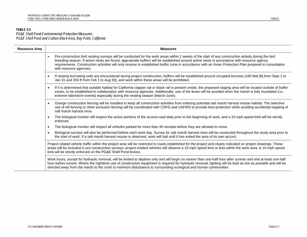
PROPOSED CORRECTIVE MEASURES PLAN AND DESIGN PG&E SHELL POND AND CARBON BLACK AREA TABLES
ES113010003017BAO\111010009 TABLES-7
TABLE 2-3 PG&E Shell Pond Environmental Protection Measures PG&E Shell Pond and Carbon Black Area, Bay Point, California
Resource Area Measures
Pre-construction bird nesting surveys will be conducted for the work areas within 2 weeks of the start of any construction activity during the bird breeding season. If active nests are found, appropriate buffers will be established around active nests in accordance with resource agency requirements. Construction activities will only resume in established buffer zone in accordance with an Avian Protection Plan prepared in consultation with resource agencies.
If nesting burrowing owls are encountered during project construction, buffers will be established around occupied burrows (160 feet [ft] from Sept 1 to Jan 31 and 250 ft from Feb 1 to Aug 30), and work within these areas will be prohibited.
If it is determined that suitable habitat for California clapper rail or black rail is present onsite, the proposed staging area will be located outside of buffer zones, to be established in collaboration with resource agencies. Additionally, use of the levee will be avoided when the marsh is fully inundated (i.e., extreme tide/storm events) especially during the nesting season (March-June).
Orange construction fencing will be installed to keep all construction activities from entering potential salt marsh harvest mouse habitat. The selective use of silt fencing or other exclusion fencing will be coordinated with CDFG and USFWS to provide best protection while avoiding accidental trapping of salt marsh harvest mice.
The biological monitor will inspect the active portions of the access road daily prior to the beginning of work, and a 10-mph speed limit will be strictly enforced.
The biological monitor will inspect all vehicles parked for more than 30 minutes before they are allowed to move.
Biological surveys will also be performed before each work day. Survey for salt marsh harvest mice will be conducted throughout the study area prior to the start of work. If a salt marsh harvest mouse is observed, work will halt until it has exited the area of its own accord.
Project-related vehicle traffic within the project area will be restricted to roads established for the project and clearly indicated on project drawings. These areas will be included in pre-construction surveys. project-related vehicles will observe a 15-mph speed limit or less within the work area. A 10-mph speed limit will be strictly enforced on the PG&E Shell Pond levees. Work hours, except for hydraulic removal, will be limited to daytime only and will begin no sooner than one-half hour after sunrise and end at least one-half hour before sunset. Where the nighttime use of construction equipment is required for hydraulic removal, lighting will be kept as low as possible and will be directed away from the marsh to the north to minimize disturbance to surrounding ecological and human communities
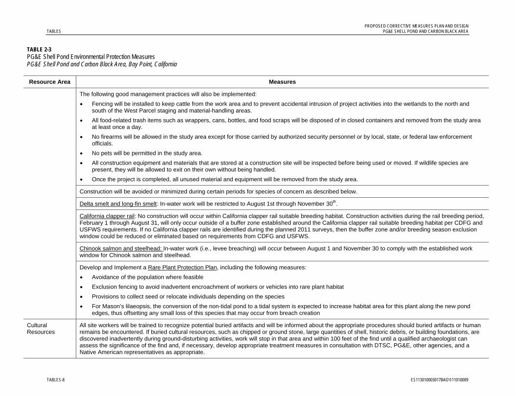
PROPOSED CORRECTIVE MEASURES PLAN AND DESIGN TABLES PG&E SHELL POND AND CARBON BLACK AREA
TABLES-8 ES113010003017BAO\111010009
TABLE 2-3 PG&E Shell Pond Environmental Protection Measures PG&E Shell Pond and Carbon Black Area, Bay Point, California
Resource Area Measures
The following good management practices will also be implemented:
Fencing will be installed to keep cattle from the work area and to prevent accidental intrusion of project activities into the wetlands to the north and south of the West Parcel staging and material-handling areas.
All food-related trash items such as wrappers, cans, bottles, and food scraps will be disposed of in closed containers and removed from the study area at least once a day.
No firearms will be allowed in the study area except for those carried by authorized security personnel or by local, state, or federal law enforcement officials.
No pets will be permitted in the study area.
All construction equipment and materials that are stored at a construction site will be inspected before being used or moved. If wildlife species are present, they will be allowed to exit on their own without being handled.
Once the project is completed, all unused material and equipment will be removed from the study area.
Construction will be avoided or minimized during certain periods for species of concern as described below.
Delta smelt and long-fin smelt: In-water work will be restricted to August 1st through November 30th.
California clapper rail: No construction will occur within California clapper rail suitable breeding habitat. Construction activities during the rail breeding period, February 1 through August 31, will only occur outside of a buffer zone established around the California clapper rail suitable breeding habitat per CDFG and USFWS requirements. If no California clapper rails are identified during the planned 2011 surveys, then the buffer zone and/or breeding season exclusion window could be reduced or eliminated based on requirements from CDFG and USFWS.
Chinook salmon and steelhead: In-water work (i.e., levee breaching) will occur between August 1 and November 30 to comply with the established work window for Chinook salmon and steelhead.
Develop and Implement a Rare Plant Protection Plan, including the following measures:
Avoidance of the population where feasible
Exclusion fencing to avoid inadvertent encroachment of workers or vehicles into rare plant habitat
Provisions to collect seed or relocate individuals depending on the species
For Mason’s lilaeopsis, the conversion of the non-tidal pond to a tidal system is expected to increase habitat area for this plant along the new pond edges, thus offsetting any small loss of this species that may occur from breach creation
Cultural Resources
All site workers will be trained to recognize potential buried artifacts and will be informed about the appropriate procedures should buried artifacts or human remains be encountered. If buried cultural resources, such as chipped or ground stone, large quantities of shell, historic debris, or building foundations, are discovered inadvertently during ground-disturbing activities, work will stop in that area and within 100 feet of the find until a qualified archaeologist can assess the significance of the find and, if necessary, develop appropriate treatment measures in consultation with DTSC, PG&E, other agencies, and a Native American representatives as appropriate.
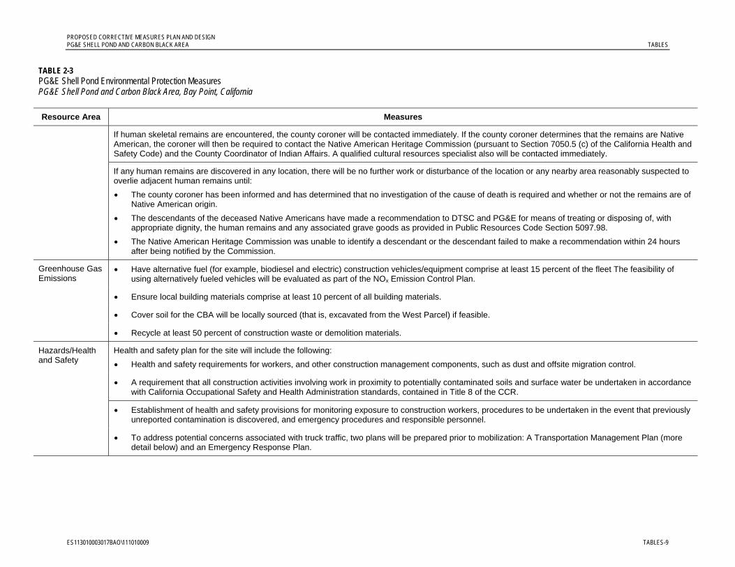
PROPOSED CORRECTIVE MEASURES PLAN AND DESIGN PG&E SHELL POND AND CARBON BLACK AREA TABLES
ES113010003017BAO\111010009 TABLES-9
TABLE 2-3 PG&E Shell Pond Environmental Protection Measures PG&E Shell Pond and Carbon Black Area, Bay Point, California
Resource Area Measures
If human skeletal remains are encountered, the county coroner will be contacted immediately. If the county coroner determines that the remains are Native American, the coroner will then be required to contact the Native American Heritage Commission (pursuant to Section 7050.5 (c) of the California Health and Safety Code) and the County Coordinator of Indian Affairs. A qualified cultural resources specialist also will be contacted immediately.
If any human remains are discovered in any location, there will be no further work or disturbance of the location or any nearby area reasonably suspected to overlie adjacent human remains until:
The county coroner has been informed and has determined that no investigation of the cause of death is required and whether or not the remains are of Native American origin.
The descendants of the deceased Native Americans have made a recommendation to DTSC and PG&E for means of treating or disposing of, with appropriate dignity, the human remains and any associated grave goods as provided in Public Resources Code Section 5097.98.
The Native American Heritage Commission was unable to identify a descendant or the descendant failed to make a recommendation within 24 hours after being notified by the Commission.
Greenhouse Gas Emissions
Have alternative fuel (for example, biodiesel and electric) construction vehicles/equipment comprise at least 15 percent of the fleet The feasibility of using alternatively fueled vehicles will be evaluated as part of the NOx Emission Control Plan.
Ensure local building materials comprise at least 10 percent of all building materials.
Cover soil for the CBA will be locally sourced (that is, excavated from the West Parcel) if feasible.
Recycle at least 50 percent of construction waste or demolition materials.
Hazards/Health and Safety
Health and safety plan for the site will include the following:
Health and safety requirements for workers, and other construction management components, such as dust and offsite migration control.
A requirement that all construction activities involving work in proximity to potentially contaminated soils and surface water be undertaken in accordance with California Occupational Safety and Health Administration standards, contained in Title 8 of the CCR.
Establishment of health and safety provisions for monitoring exposure to construction workers, procedures to be undertaken in the event that previously unreported contamination is discovered, and emergency procedures and responsible personnel.
To address potential concerns associated with truck traffic, two plans will be prepared prior to mobilization: A Transportation Management Plan (more detail below) and an Emergency Response Plan.

PROPOSED CORRECTIVE MEASURES PLAN AND DESIGN TABLES PG&E SHELL POND AND CARBON BLACK AREA
TABLES-10 ES113010003017BAO\111010009
TABLE 2-3 PG&E Shell Pond Environmental Protection Measures PG&E Shell Pond and Carbon Black Area, Bay Point, California
Resource Area Measures
As part of compliance with the National Pollutant Discharge Elimination System General Construction Permit, a Hazardous Materials Control Plan will be prepared for the construction activities, as needed, including measures and practices required to minimize the potential for, and effects from, spills of hazardous, toxic, or petroleum substances during construction of the project, storage procedures, and construction site housekeeping practices and parties responsible for monitoring and spill response, and reporting of spill incidents. Fueling and maintenance activities will be conducted offsite to the degree feasible. Some equipment, such as generators, may have to be fueled onsite. Spill response training will be provided to all site workers, and appropriate spill-response equipment will be maintained onsite. Hazardous materials will be stored as far away as possible from the sensitive habitat area, and will be located within secondary containment. Any activities involving these hazardous materials (for example, vehicle fueling and maintenance) will also be conducted in these areas, if feasible. PG&E or the construction manager will routinely inspect the project site to verify that the best management practices specified in the Hazardous Materials Control Plan are properly implemented and maintained. Use of electrical power to operate construction equipment would reduce the potential risk of fuel and oil spills within the project area.
Noise Noise avoidance and minimization measures will include the following:
Locating construction equipment staging area, material-handling areas, and stationary construction equipment as far away as possible from sensitive species foraging, nesting, or breeding habitats and residential receptors.
Shutting off idling equipment when not in use (this measure will also be implemented to reduce NOx and greenhouse gas emissions).
Selecting or contractually specifying the use of lower noise equipment.
Adding mufflers on construction equipment, generators, and vehicles.
Installing temporary barriers (shielding) around stationary construction noise sources.
Using electrically powered construction equipment where feasible.
If a sheet-pile driver is required, a vibratory hammer-type driver will be used to minimize vibration.
Truck traffic will be limited to 6 to 7 hours per day during daytime hours, and the temporary access road will be located at least 600 feet from the closest residential receptors.
Traffic and Transportation
The Transportation Management Plan prepared prior to Phase 1 of the construction effort will be augmented to include potential issues associated with the period when haul trucks are delivering non-native material (NNM) to the offsite landfill. The Transportation Management Plan will address traffic management in the vicinity of sensitive locations (schools, community center, and library) and will include measures to minimize effects on local intersections and State Route (SR) 4 during peak traffic hours. Such measures will include using alternate haul routes such as West Leland Road or Willow Pass Road, and avoiding the use of SR 4 for hauling during peak hours, discontinuing hauling activities during peak hours, and timing of onsite construction worker shifts to minimize impacts due to worker trips. The Transportation Management Plan will also address potential effects to pavement along the haul route(s). The current pavement condition will be documented by video or photo. Any roadway sections along the haul route damaged by the heavy construction vehicles will be restored to their current conditions.

PROPOSED CORRECTIVE MEASURES PLAN AND DESIGN PG&E SHELL POND AND CARBON BLACK AREA TABLES
ES113010003017BAO\111010009 TABLES-11
TABLE 2-3 PG&E Shell Pond Environmental Protection Measures PG&E Shell Pond and Carbon Black Area, Bay Point, California
Resource Area Measures
Water Quality and Wastewater Management
All wastewater generated by the project will be contained within the lined and bermed material-handling area. Water quality will be protected by ensuring that all filtrate and other water generated from the NNM removal and dewatering is returned to the Pond. No filtrate or other water that has come into contact with the NNM or additives will be released to the adjacent sloughs or tidal marshes. To prevent generation of wastewater that could not be returned to the Pond, procedures will be implemented to segregate the wastewater from the project from all other materials and wastes that could limit its potential for discharge back into the Pond. If the wastewater meets discharge requirements, it will be returned back to the PG&E Shell Pond. Water generated by ex situ stabilization of the material excavated from the wastewater ditch will be combined with any water generated from the mechanical excavation because it would contain the same constituents.
Prior to breaching the Pond for restoration, the water in the Pond will first be allowed to settle to reduce turbidity, and then tested to determine whether it is acceptable to release the water to the surrounding environment.
Water quality in the receiving water (outside the Pond) will also be protected by carefully timing the breaching process. Breaches will be completed on an incoming tide to ensure that any turbidity effects from breaching will be minimized. Breaching the Pond on an incoming tide will also result in the mixing of water from the surrounding areas with the water in the Pond, making the water released from the Pond during the ebb tide more similar to the surrounding water.
Storm Water Management
A Stormwater Pollution Prevention Plan (SWPPP) will be required as part of the project. The SWPPP will specify appropriate practices to prevent potential run-off of soils and chemicals from the project site or into sensitive areas within the project site. Stormwater collected within the bermed and lined material-handling areas will be discharged to the Pond in conjunction with the filtrate and any other water generated by the project. No fueling or refueling will be allowed onsite except where it is impractical to send vehicles and equipment offsite for fueling. When fueling must occur onsite, the contractor will designate an area to be used, in an appropriate area subject to the approval of the onsite biological monitor.


TABLE 3-1
Screening Values for Chemicals of Potential Ecological Concern - SedimentPG&E Shell Pond - Ecological Preliminary Cleanup Goals
RIVM
(2001)l
AnalyteRBV-Low
RBV--High Site 32 Site33 Site 32 Site33
Site 32Target
Site 33 Target
Site 32Not to
Exceed
Site 33Not to
Exceed TargetsNot to
Exceedt RBV-Low RBV--High RBV-Low RBV--High RBV-Low RBV--High
Aluminum 29503 29503 18000
Arsenic 29 29 15.3 13.4 15.3 8.2 70 7.4 20 7.24 41.6 35 7.2 41.6 57 700 5900 344 301 1379 1206 689 603 1380 1200
Barium 386 386 130.1 48 7200 131 263 255 512 117 459
Beryllium 1 1
Cadmium 1 1 0.33 0.25 0.33 1.2 9.6 0.38 1.4 0.68 4.21 3 0.7 4.2 5.1 9.6 820 6 5 1245 1089 12.2 10.7 124 120 0.596 77.7 1.16 152 0.177 118
Chromium 101 101 112 217 112 81 370 49 141 52.3 160 62 52.3 160 260 270 43000
Cobalt 30 30 10 3200 2.28 22.8 4.26 42.6 178 2974
Copper 67 67 68.1 65.8 68.1 34 270 32 94 18.7 108 390 18.7 108 390 1300 660 135 271 55 48 1373 1201 111 96.7 200 150 9.91 227 19.8 453 58.9 119216
Lead 44 44 43.2 30.2 43.2 46.7 218 30 94 30.24 112 400 30.2 112 450 660 63000 1 1 553 484 95 95 553 484 33 93.8 0.205 128 0.408 255 65.7 43855
Manganese 1171 1171 260
Mercury 0.2 0.2 0.43 0.35 0.15 0.71 0.14 0.48 0.13 0.7 0.41 0.59 2.1 1500 0.94 1.87 1 1 7 6 2.98 2.62 6.89 6.03
Methyl mercury
Molybdenum 9.3 9.3 23000
Nickel 128 128 112 129 112 20.9 516 15 47 15.9 42.8 110 2600
Selenium 3.5 3.5 0.64 0.22 0.64 1 9 8 37 33 12 16.1 24.18 28.3
Silver 0.5 0.58 0.304 0.58 1 3.7 0.23 1.1 0.73 1.77 3.1 6.1 6.1 71.8 171 144 341 648 3241
Thallium 2.5 2.5
Tungsten
Vanadium 125 57
Zinc 176 158 178 158 150 410 94 245 124 271 410 410 1600 6600 1208 1057 12082 10572 2420 2110 12100 10600 180 314
Ammonia
Cyanide (total)
Sulfide (total) 4.5
1-Methylnaphthalene 0.0121 0.0094 0.0121 0.021 0.094
2-Methylnaphthalene 0.0194 0.0173 0.0194 0.07 0.67 0.021 0.128 0.0202 0.201 0.67 1.9
Acenaphthene 0.0317 0.0106 0.026 0.016 0.5 0.019 0.116 0.00671 0.0889 0.13 0.00671 0.0889 0.5 2 0.135 0.284 34238 --
Acenaphthylene 0.0266 0.02 0.088 0.044 0.64 0.014 0.14 0.00587 0.128 0.071 0.00587 0.128 1.3 1.3 0.245 0.516 30.4 1503
Fluorene 0.0253 0.0127 0.0253 0.019 0.54 0.019 0.114 0.0212 0.144 0.12 0.0212 0.144 0.54 3.6
Naphthalene 0.0558 0.0558 0.0356 0.0558 0.16 2.1 0.03 0.217 0.0346 0.391 0.23 0.12 17 0.0346 0.391 2.1 2.7 17
Phenanthrene 0.237 0.115 0.237 0.24 1.5 0.068 0.455 0.0867 0.544 0.66 3.3 31 0.0867 0.544 1.5 6.9 31 0.5 2.6 1.1 5.48 222 2170
LMW PAHs 0.434 0.287 0.434 0.552 3.16 0.312 1.442 1.2 1 40 5.2 24
Benzo(a)pyrene 0.412 0.48 0.371 0.43 1.6 0.069 0.52 0.0888 0.763 1.1 0.052 7 0.0888 0.763 1.6 3.6 28 10.6 22.1 39.3 1055
Benzo(b)fluoranthene 0.371 0.617 0.371 0.13 1.107 1.8 3.6 9.9 10.6 22.1 98.9 495
Benzo(g,h,i)perylene 0.31 0.379 0.31 0.067 0.497 0.67 0.72 2.6 33 10.6 22.1 8.81 136
Chrysene 0.289 0.236 0.289 0.384 2.8 0.082 0.65 0.108 0.846 0.95 8.1 35 0.108 0.846 2.8 9.2 35 11.9 24.7 3607.0 19038
Indeno(1,2,3-cd)pyrene 0.412 0.382 0.394 0.382 0.068 0.488 0.6 0.69 2.6 1.9 10.6 22.1 452.0 2261
Pyrene 0.665 0.665 0.544 0.665 0.665 2.6 0.125 0.932 0.153 1.398 2.4 0.153 1.398 3.3 16 0.0265 0.0558 689
HMW PAHs 3.06 3.995 3.06 1.7 9.6 0.655 6.676 7.9 1 40 17 69
Total PAHs 3.39 3.39 4.28 3.39 4.022 44.792 1.684 16.77 1 40
Mercaptans
Benzoic acid 0.065 0.65 0.76
Bis(2-ethylhexyl)phthalate 0.182 2.647 1.3 0.1 10 1.3 1.9
Dimethyl phthalate 0.006 1 84 0.16 0.16 84
1,2,3-Trimethylbenzene
Ethylbenzene 0.004 0.03 50 0.01 0.037 110
n-Butylbenzene
p-Isopropyltoluene
Tetrachloroethene 0.057 0.002 4 0.057 0.14 16
Xylene (total) 0.004 0.13 17 0.04 0.12 17
Notes:
EcoPCG-Low = Ecological preliminary clean-up goal based on low toxicity reference values
EcoPCG-High = Ecological preliminary clean-up goal based on high toxicity reference values
ER-L = Effects range low
ER-M = Effects range median
PEL = Probable Effects Level
AET- Apparent Effects Threshold
ISQG = Interim sediment quality guideline
SRC = Serious Risk Concentration, concentration at which 50% of test organisms may encounter adverse effectsT20 - concentration corresponding to the 20% proportion of toxic samples for amphipod survival
T50 - concentration corresponding to the 50% proportion of toxic samples for amphipod survival
PRG - preliminary remedial goal
RG - remedial goal
RBV - risk based value
Low sediment benchmarks, quality criteria, and/or risk-based values
High sediment benchmarks, quality criteria, and/or risk based values
Recommended EcoPCGs
NWS Seal Beach Detachment Concordn
Former NAS Moffet
Fieldr
Clapper RailFinal Remedial Goals
Hamilton - North Antenna Fieldu
Project-specific Remedial Goals (mg/kg)
AET-H
Final Area-weighted Remedial GoalspSurf Scoter
Low TRV-based
PRGso
SRCeco
High TRV-based
PRGsoSFB-
RWQCB Wetland Surface
Materiale
Field et al. (2002)g
Canadian Environmental Quality
Guidelinesi
PEL AET-L
Long et al. (1995)f
PEL AETDutch-Target
Dutch-Intervention ISQG
Black RailSalt Marsh Harvest
Mouse
Ambient Concentrations (mg/kg)
PG&E Shell
Ponda
San Francisco
Estuaryc
(<100% fines)
San Pablo Bay/ Carquinez Reference
Sitesd
General Chemical Corp. Bay
Point
Worksb TELER-L ER-M T20 T50
Barrick et al. (1988)j,kBuchman (2008)h
Sediment Quality Benchmarks and Guidelines (mg/kg)Hunters Point
Shipyard - Parcel
Fm
Eco_PCGs_05162010_SUM/Table 3_ESLs_sediment 1 of 4

TABLE 3-1
Screening Values for Chemicals of Potential Ecological Concern - SedimentPG&E Shell Pond - Ecological Preliminary Cleanup Goals
RIVM
(2001)l
AnalyteRBV-Low
RBV--High Site 32 Site33 Site 32 Site33
Site 32Target
Site 33 Target
Site 32Not to
Exceed
Site 33Not to
Exceed TargetsNot to
Exceedt RBV-Low RBV--High RBV-Low RBV--High RBV-Low RBV--High
NWS Seal Beach Detachment Concordn
Former NAS Moffet
Fieldr
Clapper RailFinal Remedial Goals
Hamilton - North Antenna Fieldu
Project-specific Remedial Goals (mg/kg)
AET-H
Final Area-weighted Remedial GoalspSurf Scoter
Low TRV-based
PRGso
SRCeco
High TRV-based
PRGsoSFB-
RWQCB Wetland Surface
Materiale
Field et al. (2002)g
Canadian Environmental Quality
Guidelinesi
PEL AET-L
Long et al. (1995)f
PEL AETDutch-Target
Dutch-Intervention ISQG
Black RailSalt Marsh Harvest
Mouse
Ambient Concentrations (mg/kg)
PG&E Shell
Ponda
San Francisco
Estuaryc
(<100% fines)
San Pablo Bay/ Carquinez Reference
Sitesd
General Chemical Corp. Bay
Point
Worksb TELER-L ER-M T20 T50
Barrick et al. (1988)j,kBuchman (2008)h
Sediment Quality Benchmarks and Guidelines (mg/kg)Hunters Point
Shipyard - Parcel
Fm
Sources:a Background for metals defined in Montgomery Watson (2000, 2001) and cited Entrix (2009b). Background for organics based on ambient sediment concentrations (>40% fines) defined in SFEI (2008) as cited in Entrix (2009b).b Montgomery Watson. 2000. Background Metal Concentrations in Soil. General Chemical Corporation, Bay Pont Works Facility, Pittsburg, CA. May 15.c Reported in SFB-RWQCB (2000).d Maximum of values reported for Paradise Cove (92.9% fines), Tubbs Island (99.4% fines), and Island #1 (99% fines) in SFB-RWQCB (2000).e SFB-RWCB 2000. Draft Staff Report: Beneficial use of dredged materials: Sediment screening and testing guidelines. May.f Long, E.R., D.D. MacDonald, S.L. Smith, and F.D. Calder. 1995. Incidence of adverse biological effects within ranges of chemical concentrations in marine and estuarine sediments. Environ. Manage. 19: 81-97g Field, L.J., D,D. MacDonald, S.B Norton, C.G. Ingersoll, C.G. Severn, D. Smorong, and R. Lindskoog. 2002. Predicting amphipod toxicity from sediment chemistry using logistic regression models. Environ. Toxicol. Chem. 21:1993-2005.h Buchman, M.F. 2008. NOAA Screening Quick Reference Tables NOAA OR&R Report 08-1, Seattle, WA, Office of Response and Restoration Division, National Oceanic and Atmospheric Administration, 34 p.i Canadian Council of Ministers of the Environment (CCME). 2003. Canadian Environmental Quality Guidelines, Summary Table: Summary of Existing Canadian Environmental Quality Guidelines, Canadian Council of Ministers of the Environment, Winnipeg. December.j Barrick, R., S. Becker, L. Brown, H. Beller, and R. Pastorok. 1988. Sediment quality values refinement: 1988 update and evaluation of Puget Sound AET. Vol. 1. Prepared for the Puget Sound Estuary Program, Office of Puget Sound. Values used as cited in USEPA 1997.k USEPA. 1997. The incidence and severity of sediment contamination in surface waters of the United States, Vol. 1. National sediment quality survey. United States Environmental Protection Agency. Office of Science and Technology. EPA 823-R-97-006. September.l RIVM. 2001. Rijksinstituut Voor Volksgezondheid en Milieu (National Institute of Public Health and the Environment). RIVM Report 7111701 023. Technical evaluation of the intervention values for soil/sediment and groundwater: Human and ecotoxicological risk assessment derivation of risk limits for soil, aquatic sediment, and groundwater. February.m Barajas and Associates, Inc. 2008. Feasibility study report for Parcel F, Hunters Point Shipyard, San Francisco, California. BAI.5106.0004.0003. April.n Tetra Tech EM Inc. 2008. Final Supplemental Feasibility Study Report for Litigation Area Site 32 (Unit 7 Mosquito Abatement Ditches) 33 (Units 10 and 11, Lost Slough), and 34 (Nichols Creek Erosional Areas). Naval Weapons Station Seal Beach, Detachment Concord, Concord, California. Prepared for Naval Facilities Engineering Command Southwest Desert IPT. January.o Preliminary remedial goals were back-calculated using Low and High TRVs for California black rail, Virginia rail, Suisun song sparrow, mallard, great blue heron, and river otter. Values for the Virginia rail were the most conservative and were selected to use in deriving the Final Remedial Goals.p Final Remedial Goals were area-weighted. The Not to Exceed" value was derived using the High TRV-based PRG and adjusted downward for each subarea until the area-weighted goals were equal to twice the Low TRV-based PRG or ambient concentrations (whichever was higher).r Tetra Tech EM Inc. 2009. Proposed Plan for Former Naval Air Station Moffett Field, Site 25, Moffett Field, California. January.s Target remedial goals were based on site background valuest Not to Exceed goal is a risk based goal.u CH2M HILL. 2007. Technical Memorandum, Focused Feasibility Study, Human Health and Ecological Risk Assessment, Hamilton Army Airfield, North Antenna Field, California. April.
Eco_PCGs_05162010_SUM/Table 3_ESLs_sediment 2 of 4
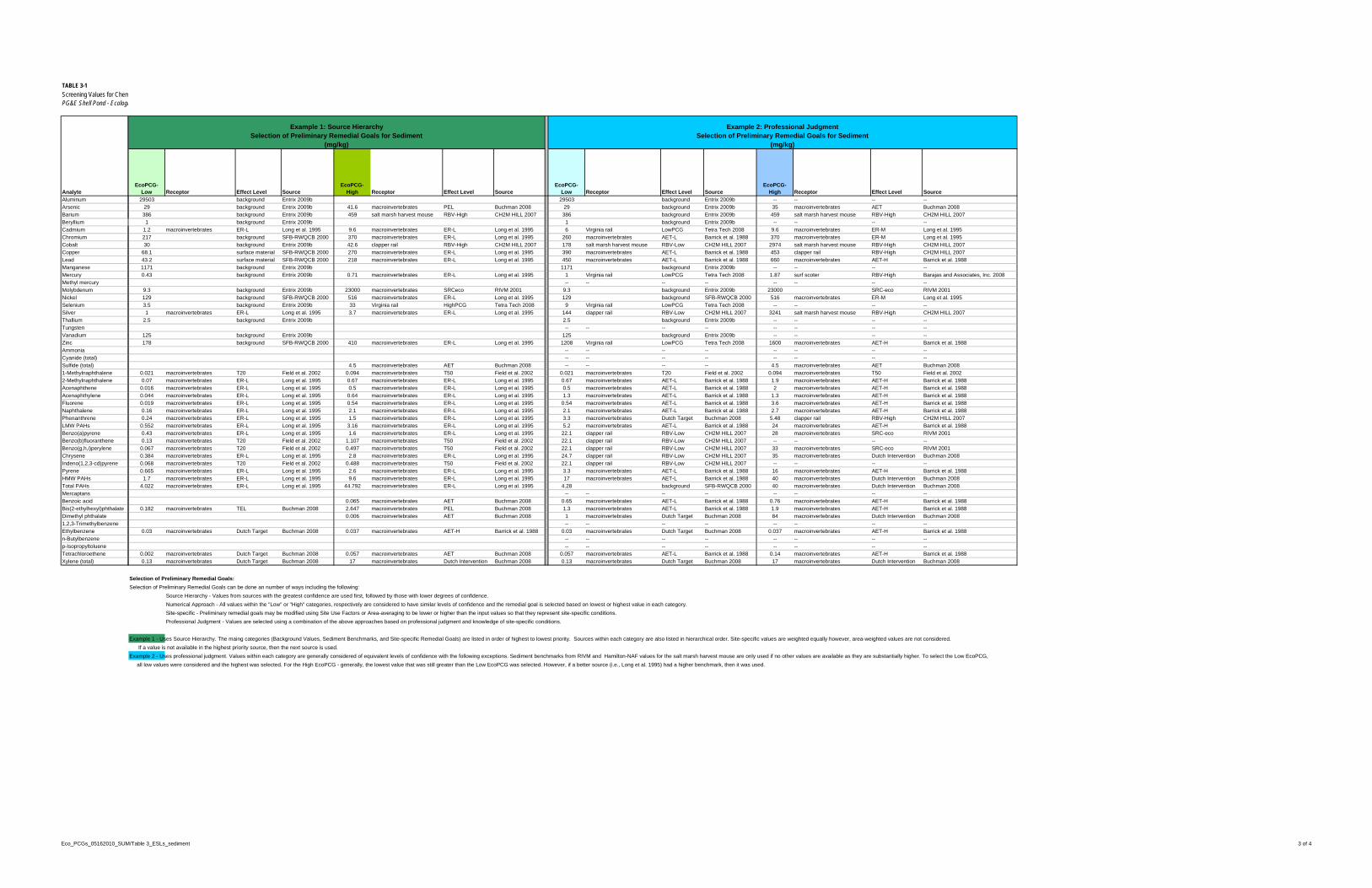
TABLE 3-1
Screening Values for ChemPG&E Shell Pond - Ecologi
Analyte
Aluminum
Arsenic
Barium
Beryllium
Cadmium
Chromium
Cobalt
Copper
Lead
Manganese
Mercury
Methyl mercury
Molybdenum
Nickel
Selenium
Silver
Thallium
Tungsten
Vanadium
Zinc
Ammonia
Cyanide (total)
Sulfide (total)
1-Methylnaphthalene
2-Methylnaphthalene
Acenaphthene
Acenaphthylene
Fluorene
Naphthalene
Phenanthrene
LMW PAHs
Benzo(a)pyrene
Benzo(b)fluoranthene
Benzo(g,h,i)perylene
Chrysene
Indeno(1,2,3-cd)pyrene
Pyrene
HMW PAHs
Total PAHs
Mercaptans
Benzoic acid
Bis(2-ethylhexyl)phthalate
Dimethyl phthalate
1,2,3-Trimethylbenzene
Ethylbenzene
n-Butylbenzene
p-Isopropyltoluene
Tetrachloroethene
Xylene (total)
29503 background Entrix 2009b 29503 background Entrix 2009b -- -- -- --
29 background Entrix 2009b 41.6 macroinvertebrates PEL Buchman 2008 29 background Entrix 2009b 35 macroinvertebrates AET Buchman 2008
386 background Entrix 2009b 459 salt marsh harvest mouse RBV-High CH2M HILL 2007 386 background Entrix 2009b 459 salt marsh harvest mouse RBV-High CH2M HILL 2007
1 background Entrix 2009b 1 background Entrix 2009b -- -- -- --
1.2 macroinvertebrates ER-L Long et al. 1995 9.6 macroinvertebrates ER-L Long et al. 1995 6 Virginia rail LowPCG Tetra Tech 2008 9.6 macroinvertebrates ER-M Long et al. 1995
217 background SFB-RWQCB 2000 370 macroinvertebrates ER-L Long et al. 1995 260 macroinvertebrates AET-L Barrick et al. 1988 370 macroinvertebrates ER-M Long et al. 1995
30 background Entrix 2009b 42.6 clapper rail RBV-High CH2M HILL 2007 178 salt marsh harvest mouse RBV-Low CH2M HILL 2007 2974 salt marsh harvest mouse RBV-High CH2M HILL 2007
68.1 surface material SFB-RWQCB 2000 270 macroinvertebrates ER-L Long et al. 1995 390 macroinvertebrates AET-L Barrick et al. 1988 453 clapper rail RBV-High CH2M HILL 2007
43.2 surface material SFB-RWQCB 2000 218 macroinvertebrates ER-L Long et al. 1995 450 macroinvertebrates AET-L Barrick et al. 1988 660 macroinvertebrates AET-H Barrick et al. 1988
1171 background Entrix 2009b 1171 background Entrix 2009b -- -- -- --
0.43 background Entrix 2009b 0.71 macroinvertebrates ER-L Long et al. 1995 1 Virginia rail LowPCG Tetra Tech 2008 1.87 surf scoter RBV-High Barajas and Associates, Inc. 2008
-- -- -- -- -- -- -- --
9.3 background Entrix 2009b 23000 macroinvertebrates SRCeco RIVM 2001 9.3 background Entrix 2009b 23000 SRC-eco RIVM 2001
129 background SFB-RWQCB 2000 516 macroinvertebrates ER-L Long et al. 1995 129 background SFB-RWQCB 2000 516 macroinvertebrates ER-M Long et al. 1995
3.5 background Entrix 2009b 33 Virginia rail HighPCG Tetra Tech 2008 9 Virginia rail LowPCG Tetra Tech 2008 -- -- -- --
1 macroinvertebrates ER-L Long et al. 1995 3.7 macroinvertebrates ER-L Long et al. 1995 144 clapper rail RBV-Low CH2M HILL 2007 3241 salt marsh harvest mouse RBV-High CH2M HILL 2007
2.5 background Entrix 2009b 2.5 background Entrix 2009b -- -- -- --
-- -- -- -- -- -- -- --
125 background Entrix 2009b 125 background Entrix 2009b -- -- -- --
178 background SFB-RWQCB 2000 410 macroinvertebrates ER-L Long et al. 1995 1208 Virginia rail LowPCG Tetra Tech 2008 1600 macroinvertebrates AET-H Barrick et al. 1988
-- -- -- -- -- -- -- --
-- -- -- -- -- -- -- --
4.5 macroinvertebrates AET Buchman 2008 -- -- -- -- 4.5 macroinvertebrates AET Buchman 2008
0.021 macroinvertebrates T20 Field et al. 2002 0.094 macroinvertebrates T50 Field et al. 2002 0.021 macroinvertebrates T20 Field et al. 2002 0.094 macroinvertebrates T50 Field et al. 2002
0.07 macroinvertebrates ER-L Long et al. 1995 0.67 macroinvertebrates ER-L Long et al. 1995 0.67 macroinvertebrates AET-L Barrick et al. 1988 1.9 macroinvertebrates AET-H Barrick et al. 1988
0.016 macroinvertebrates ER-L Long et al. 1995 0.5 macroinvertebrates ER-L Long et al. 1995 0.5 macroinvertebrates AET-L Barrick et al. 1988 2 macroinvertebrates AET-H Barrick et al. 1988
0.044 macroinvertebrates ER-L Long et al. 1995 0.64 macroinvertebrates ER-L Long et al. 1995 1.3 macroinvertebrates AET-L Barrick et al. 1988 1.3 macroinvertebrates AET-H Barrick et al. 1988
0.019 macroinvertebrates ER-L Long et al. 1995 0.54 macroinvertebrates ER-L Long et al. 1995 0.54 macroinvertebrates AET-L Barrick et al. 1988 3.6 macroinvertebrates AET-H Barrick et al. 1988
0.16 macroinvertebrates ER-L Long et al. 1995 2.1 macroinvertebrates ER-L Long et al. 1995 2.1 macroinvertebrates AET-L Barrick et al. 1988 2.7 macroinvertebrates AET-H Barrick et al. 1988
0.24 macroinvertebrates ER-L Long et al. 1995 1.5 macroinvertebrates ER-L Long et al. 1995 3.3 macroinvertebrates Dutch Target Buchman 2008 5.48 clapper rail RBV-High CH2M HILL 2007
0.552 macroinvertebrates ER-L Long et al. 1995 3.16 macroinvertebrates ER-L Long et al. 1995 5.2 macroinvertebrates AET-L Barrick et al. 1988 24 macroinvertebrates AET-H Barrick et al. 1988
0.43 macroinvertebrates ER-L Long et al. 1995 1.6 macroinvertebrates ER-L Long et al. 1995 22.1 clapper rail RBV-Low CH2M HILL 2007 28 macroinvertebrates SRC-eco RIVM 2001
0.13 macroinvertebrates T20 Field et al. 2002 1.107 macroinvertebrates T50 Field et al. 2002 22.1 clapper rail RBV-Low CH2M HILL 2007 -- -- -- --
0.067 macroinvertebrates T20 Field et al. 2002 0.497 macroinvertebrates T50 Field et al. 2002 22.1 clapper rail RBV-Low CH2M HILL 2007 33 macroinvertebrates SRC-eco RIVM 2001
0.384 macroinvertebrates ER-L Long et al. 1995 2.8 macroinvertebrates ER-L Long et al. 1995 24.7 clapper rail RBV-Low CH2M HILL 2007 35 macroinvertebrates Dutch Intervention Buchman 2008
0.068 macroinvertebrates T20 Field et al. 2002 0.488 macroinvertebrates T50 Field et al. 2002 22.1 clapper rail RBV-Low CH2M HILL 2007 -- -- -- --
0.665 macroinvertebrates ER-L Long et al. 1995 2.6 macroinvertebrates ER-L Long et al. 1995 3.3 macroinvertebrates AET-L Barrick et al. 1988 16 macroinvertebrates AET-H Barrick et al. 1988
1.7 macroinvertebrates ER-L Long et al. 1995 9.6 macroinvertebrates ER-L Long et al. 1995 17 macroinvertebrates AET-L Barrick et al. 1988 40 macroinvertebrates Dutch Intervention Buchman 2008
4.022 macroinvertebrates ER-L Long et al. 1995 44.792 macroinvertebrates ER-L Long et al. 1995 4.28 background SFB-RWQCB 2000 40 macroinvertebrates Dutch Intervention Buchman 2008
-- -- -- -- -- -- -- --
0.065 macroinvertebrates AET Buchman 2008 0.65 macroinvertebrates AET-L Barrick et al. 1988 0.76 macroinvertebrates AET-H Barrick et al. 1988
0.182 macroinvertebrates TEL Buchman 2008 2.647 macroinvertebrates PEL Buchman 2008 1.3 macroinvertebrates AET-L Barrick et al. 1988 1.9 macroinvertebrates AET-H Barrick et al. 1988
0.006 macroinvertebrates AET Buchman 2008 1 macroinvertebrates Dutch Target Buchman 2008 84 macroinvertebrates Dutch Intervention Buchman 2008
-- -- -- -- -- -- -- --
0.03 macroinvertebrates Dutch Target Buchman 2008 0.037 macroinvertebrates AET-H Barrick et al. 1988 0.03 macroinvertebrates Dutch Target Buchman 2008 0.037 macroinvertebrates AET-H Barrick et al. 1988
-- -- -- -- -- -- -- --
-- -- -- -- -- -- -- --
0.002 macroinvertebrates Dutch Target Buchman 2008 0.057 macroinvertebrates AET Buchman 2008 0.057 macroinvertebrates AET-L Barrick et al. 1988 0.14 macroinvertebrates AET-H Barrick et al. 1988
0.13 macroinvertebrates Dutch Target Buchman 2008 17 macroinvertebrates Dutch Intervention Buchman 2008 0.13 macroinvertebrates Dutch Target Buchman 2008 17 macroinvertebrates Dutch Intervention Buchman 2008
Selection of Preliminary Remedial Goals:
Selection of Preliminary Remedial Goals can be done an number of ways including the following:
Source Hierarchy - Values from sources with the greatest confidence are used first, followed by those with lower degrees of confidence.
Numerical Approach - All values within the "Low" or "High" categories, respectively are considered to have similar levels of confidence and the remedial goal is selected based on lowest or highest value in each category.
Site-specific - Preliminary remedial goals may be modified using Site Use Factors or Area-averaging to be lower or higher than the input values so that they represent site-specific conditions.
Professional Judgment - Values are selected using a combination of the above approaches based on professional judgment and knowledge of site-specific conditions.
Example 1 - Uses Source Hierarchy. The maing categories (Background Values, Sediment Benchmarks, and Site-specific Remedial Goals) are listed in order of highest to lowest priority. Sources within each category are also listed in hierarchical order. Site-specific values are weighted equally however, area-weighted values are not considered.
If a value is not available in the highest priority source, then the next source is used.
Example 2 - Uses professional judgment. Values within each category are generally considered of equivalent levels of confidence with the following exceptions. Sediment benchmarks from RIVM and Hamilton-NAF values for the salt marsh harvest mouse are only used if no other values are available as they are substantially higher. To select the Low EcoPCG,
all low values were considered and the highest was selected. For the High EcoPCG - generally, the lowest value that was still greater than the Low EcoPCG was selected. However, if a better source (i.e., Long et al. 1995) had a higher benchmark, then it was used.
Source
Example 2: Professional JudgmentSelection of Preliminary Remedial Goals for Sediment
(mg/kg)
EcoPCG-Low Receptor Effect Level Source
EcoPCG-High Receptor Effect LevelEffect Level
Example 1: Source HierarchySelection of Preliminary Remedial Goals for Sediment
(mg/kg)
EcoPCG-Low Receptor Effect Level Source
EcoPCG-High SourceReceptor
Eco_PCGs_05162010_SUM/Table 3_ESLs_sediment 3 of 4


PROPOSED CORRECTIVE MEASURES PLAN AND DESIGN PG&E SHELL POND AND CARBON BLACK AREA TABLES
ES113010003017BAO\111010009 TABLES-15
TABLE 3-2 Approved Remediation Goals PG&E Shell Pond and Carbon Black Area, Bay Point, California
Analyte Low EcoPRG
(mg/kg) High EcoPRG
(mg/kg)
Chromium 217 370
Cobalt 30 42.6
Copper 68.1 270
Lead 43.2 218
Mercury 0.43 0.71
Molybdenum 9.3 23000
Nickel 129 516
Sulfide (total) n.a. 4.5
1-Methylnaphthalene 0.021 0.094
2-Methylnaphthalene 0.07 0.67
Acenaphthene 0.016 0.5
Acenaphthylene 0.044 0.64
Fluorene 0.019 0.54
Naphthalene 0.16 2.1
Phenanthrene 0.24 1.5
LMW PAHs 0.552 3.16
Benzo(a)pyrene 0.43 1.6
Benzo(b)fluoranthene 0.13 1.107
Benzo(g,h,i)perylene 0.067 0.497
Chrysene 0.384 2.8
Indeno(1,2,3-cd)pyrene 0.068 0.488
Pyrene 0.665 2.6
HMW PAHs 1.7 9.6
Total PAHs 4.022 44.792
Notes EcoPRG = ecological preliminary remediation goal HMW = high molecular weight LMW = low molecular weight mg/kg = milligrams per kilogram n.a. = not applicable PAH = polycyclic aromatic hydrocarbon


PROPOSED CORRECTIVE MEASURES PLAN AND DESIGN PG&E SHELL POND AND CARBON BLACK AREA TABLES
ES113010003017BAO\111010009 TABLES-17
TABLE 4-1 Corrective Measures Elements PG&E Shell Pond and Carbon Black Area, Bay Point, California
Element Description Design Basis or Rationale
Constructed Elements (Phase 1)
The following elements are construction activities that are necessary prior to implementing the remediation of the site.
These activities will occur outside of wetlands and the jurisdiction of the U.S. Army Corps of Engineers (USACE) and the Bay Conservation and Development Commission (BCDC); therefore permits from these agencies are not required. These activities require local county permits for grading and bridge construction and California Environmental Quality Act (CEQA) documentation.
1. Access Road and Bridge The Access Road will cross the PG&E property adjacent to the west of the PG&E Shell Pond. This temporary gravel road will enable site traffic to access the project via a protected /controlled railroad crossing. This access road includes a temporary bridge to span a drainage ditch near the southwest corner of the PG&E Shell Pond.
a. New Access Road & Improvement of Existing Road
4,574 linear feet of new access road
1,185 linear feet of road improvement
• 16 inches Class 2 AB (Aggregate Base) • Class B1 SEG (Subgrade Enhancement Geotextile
underlying AB)
• Site R-Value = <5 • Subgrade Enhanced R-Value = 20 • 80 trucks per day • 1-year construction period (truck traffic) • 20-ton, 4-axle trucks
b. Temporary Bridge Structure
55' L x 13" W portable, modular bridge prefabricated by ADM Welding & Fabrication
Length of bridge designed to keep foundation out of creek to avoid regulatory agency permitting.
Temporary Bridge (total load per abutment):
• Superstructure: 18,500 pounds (lbs) (13’W x 55’L bridge) • Foundation: 33,300 lbs • Maximum live load: 73,200 lbs

PROPOSED CORRECTIVE MEASURES PLAN AND DESIGN TABLES PG&E SHELL POND AND CARBON BLACK AREA
TABLES-18 ES113010003017BAO\111010009
TABLE 4-1 Corrective Measures Elements PG&E Shell Pond and Carbon Black Area, Bay Point, California
Element Description Design Basis or Rationale
2. Geotextile Tube Material Handling Area
A Material Handling Area for temporary containment of hydraulically removed non-native material (NNM) in the PG&E Shell Pond will be constructed by re-grading an area west of the PG&E Shell Pond. The Material Handling Area will consist of a perimeter soil berm, impermeable geomembrane, and cushion layer (geotextile or sand) overlain by drainage materials and a woven geotextile. The base of the area will be sloped 0.5% to drain to a sump from which filtrate water can be pumped back to the PG&E Shell Pond to maintain water level for hydraulic removal of the NNM. The interior final surface will be level as required for stacking and management of the geotextile tubes. The Material Handling Area has ramps to allow haul truck access for loading of the dewatered material and exiting and truck washing for offsite disposal at a permitted landfill.
• Exterior Dimensions (footprint) = 770 ft x 448 ft (344,960 sf)
• Interior Dimensions (lay down area) = 698 ft x 378 ft (263,844 sf)
Location and size of Material Handling Area was developed to avoid potential wetlands, allow for some existing tenant facilities, and accommodate the necessary amount of geotextile filter bags.
The NNM is classified as non-hazardous suitable for disposal at a Class II permitted facility.
Geotextile is recommended on top of the rock drainage layer to maintain operational efficiency and cleanliness because geotextile bags will be removed and replaced within the Material Handling Area as opposed to one-time placement filling and removal of geotextile tubes. This approach is necessary because the size of the Material Handling Area is limited, and PG&E’s goal is to complete as much work as possible by the end of 2011.
The Carbon Black Area (CBA) was removed from consideration for material handling of hydraulically removed NNM because resource agency permits would require modification and approval because of wetlands in this area, road improvements would require extension east to the CBA and truck transport distances, and associated air emissions would be greater.
a. Piping In Approximately 775 linear feet of piping to be constructed to carry NNM and water mixture from hydraulic removal dredges to gravity thickeners and into the geotextile tubes set up in the Materials Handling Area. Piping to be fastened to side of temporary bridge.
Two hydraulic dredges with 8-inch-diameter discharge.
• Two 8-inch-diameter pipelines from dredges to gravity thickeners.
• Polymer to be added in-line prior to gravity thickeners with provision to add additional polymer after the gravity thickener.
b. Piping Out
Approximately 885 linear feet of piping to be constructed to carry filtrate water back to PG&E Shell Pond. The filtrate water is generated from dewatering of NNM in the geotextile bags.
14-inch-diameter piping from sump in Material Handling Area back to PG&E Shell Pond with possible input from gravity thickener overflow.
c. Ramps to Containment Area
Approximately 1,077 linear feet of new ramps will be constructed from the new access road to the Material Handling Area.
Truck traffic for loading and hauling of dewatered material will enter Material Handling Area from east and exit at west where the exit ramp is lengthened to allow for truck washing. Liquid from truck washing will be recycled ,and excess will drain back into Material Handling Area. Nonpotable water will be provided from the Contra Costa Water District pipeline at the south end of PG&E Shell Pond or similar acceptable sources.

PROPOSED CORRECTIVE MEASURES PLAN AND DESIGN PG&E SHELL POND AND CARBON BLACK AREA TABLES
ES113010003017BAO\111010009 TABLES-19
TABLE 4-1 Corrective Measures Elements PG&E Shell Pond and Carbon Black Area, Bay Point, California
Element Description Design Basis or Rationale
Remediation and CBA Improvement Elements (Phase 2)
The following elements are the remediation activities and CBA improvements for the project. The actual schedule for these activities is dependent on receipt of permissions and permits from regulatory agencies.
Remediation activities are dependent on receipt of permissions and permits from resource and regulatory agencies (including U.S. Army Corps of Engineers (USACE) 404 permit, California Regional Water Quality Control Board 401 certification, and Bay Conservation and Development Commission (BCDC) permit). Receipt of these permits is expected to be completed no later than June 2011. Conditions of these permits will be incorporated into the implementation of these activities.
1. Removal of NNM from PG&E Shell Pond
Removal of an estimated total of 240,000 cubic yards (CY)of NNM from the PG&E Shell Pond is planned using hydraulic and mechanical removal methods. Post-removal confirmation samples will provide the basis to demonstrate that the removal actions are complete and remediation goals are achieved.
Volume was originally estimated based on average thicknesses of areas as described in Corrective Measures Study (CH2MHILL, 2010a) plus an additional allowance of 0.5 foot over the entire pond area. Computer drawing calculations using isopach maps of the native material thickness (see 30% Design Drawings) resulted in an approximate 14% lower volume estimates. Because removal will not exactly follow isopach maps, the total volume for removal was not changed. The volumes listed below are scaled from the computer drawing calculations.
a. Hydraulic Removal
Hydraulic removal of an estimated 197,000 CY of material consists of using horizontal auger dredges that pump material through pipes to the geotextile filter bags in the Material Handling Area.
Material to be removed includes:
• 142,700 CY NNM • 54,300 CY removal allowance(6” below non-native)
Hydraulic removal is proposed for the majority of the PG&E Shell Pond, where water covers the NNM. Minimum water elevation in the pond will be maintained at 7 feet through a combination of return filtrate and pumping of water from the east channel.
Hydraulic removal was selected for three primary reasons:
1. Speed of Excavation: Hydraulic removal provides a higher removal efficiency compared with mechanical excavation. 24 hours per day, 6 days a week operations for hydraulic removal will allow for removal to be completed by the end of 2011.
2. Odor Control: PG&E has previously received complaints from neighbors about odors from the pond that are emitted when the pond dries out. For this reason, PG&E has kept the pond full of water. Hydraulic removal allows for maintenance of the water cover, which reduces odors.
3. Organic Soil and Peat: The northern portion of the pond is underlain by soft organic soil and peat that is up to about 8 feet thick. This makes access for even, low-pressure excavation equipment more difficult and presents a greater safety risk.
Loading and offhaul of material will begin no later than 30 days after filling of geotextile tube so that new tube can be placed and filled.

PROPOSED CORRECTIVE MEASURES PLAN AND DESIGN TABLES PG&E SHELL POND AND CARBON BLACK AREA
TABLES-20 ES113010003017BAO\111010009
TABLE 4-1 Corrective Measures Elements PG&E Shell Pond and Carbon Black Area, Bay Point, California
Element Description Design Basis or Rationale
b. Mechanical Removal
Mechanical removal of an estimated 43,000 CY of material from the southern end of the pond (approximately 11 to 12 acres). Mechanical removal consists of using conventional land-based excavation equipment.
Material to be removed includes:
• 33,200 CY NNM • 9,800 CY native material (6” below non-native)
Mechanical excavation is proposed for the south end of the pond where there would be less than 18 inches of water covering the NNM. This is an insufficient amount of water to hydraulically remove the NNM.
Mechanical excavation for the southern end was selected for three primary reasons:
1. The south end of the pond is typically dry most of the year and has not resulted in odor problems, although material below surface has odors in some areas as noted during the pilot test.
2. The southern end is a higher elevation and it would be difficult to flood the area to the 18 inches water required for hydraulic removal.
3. The material underlying the soft, NNM is a generally a stiff, light brown, alluvial clay which makes the area more accessible for low-pressure excavation equipment compared to the northern portion of the pond.
4. Isolation of this area with temporary berms will be necessary to keep water in the northern portion of the pond from entering the mechanical removal area.
2. Wastewater Ditch Removal Removal of 300 to 600 CY of NNM from the wastewater ditch at the southern end of the site. Excavation will be completed using the mechanical methods used in the southern portion of the pond.
Volume based on:
Length: 1176 feet Width: 4 to 6 feet (varies) Depth: 1 to 3 feet (varies)
Entrix (2009a) sampling results indicated several soil samples exceeding the polycyclic aromatic hydrocarbon (PAH) remediation goals. The volume of NNM to be excavated from the wastewater ditch was calculated based on assumptions developed from the Entrix investigation. Removal will be based on visual observations and confirmed by collection and analysis of confirmation samples. Some initial trenching across the wastewater ditch may be performed to evaluate removal extent.
3. Water Management Water will be generated from the following sources:
• Filtrate (seepage) from geotextile tubes during hydraulic excavation and dewatering
• Ex situ mixing of the material removed during mechanical excavation
• Wash down of construction equipment
Water will be managed as described in the Waste and Water Management Plan (Appendix B).
All filtrate water will be returned to the PG&E Shell Pond. Filtrate water from the dewatering of material removed from the pond will be piped back to the PG&E Shell Pond. Water in the pond will be sampled prior to restoration. If water exceeds applicable Basin Plan criteria, then it will be treated or removed prior to breaching of the levee to restore tidal action to the PG&E Shell Pond (e.g., discharge). Construction washdown water will be recirculated and either lost to evaporation or returned to pond.
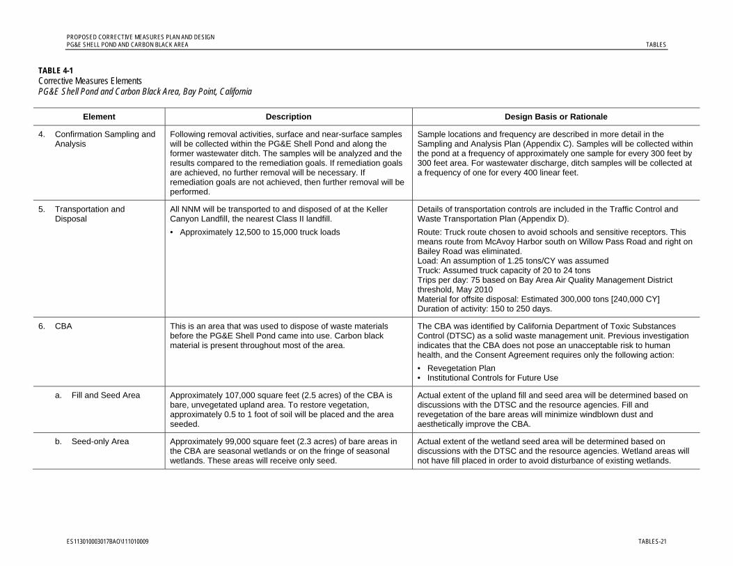
PROPOSED CORRECTIVE MEASURES PLAN AND DESIGN PG&E SHELL POND AND CARBON BLACK AREA TABLES
ES113010003017BAO\111010009 TABLES-21
TABLE 4-1 Corrective Measures Elements PG&E Shell Pond and Carbon Black Area, Bay Point, California
Element Description Design Basis or Rationale
4. Confirmation Sampling and Analysis
Following removal activities, surface and near-surface samples will be collected within the PG&E Shell Pond and along the former wastewater ditch. The samples will be analyzed and the results compared to the remediation goals. If remediation goals are achieved, no further removal will be necessary. If remediation goals are not achieved, then further removal will be performed.
Sample locations and frequency are described in more detail in the Sampling and Analysis Plan (Appendix C). Samples will be collected within the pond at a frequency of approximately one sample for every 300 feet by 300 feet area. For wastewater discharge, ditch samples will be collected at a frequency of one for every 400 linear feet.
5. Transportation and Disposal
All NNM will be transported to and disposed of at the Keller Canyon Landfill, the nearest Class II landfill.
• Approximately 12,500 to 15,000 truck loads
Details of transportation controls are included in the Traffic Control and Waste Transportation Plan (Appendix D).
Route: Truck route chosen to avoid schools and sensitive receptors. This means route from McAvoy Harbor south on Willow Pass Road and right on Bailey Road was eliminated. Load: An assumption of 1.25 tons/CY was assumed Truck: Assumed truck capacity of 20 to 24 tons Trips per day: 75 based on Bay Area Air Quality Management District threshold, May 2010 Material for offsite disposal: Estimated 300,000 tons [240,000 CY] Duration of activity: 150 to 250 days.
6. CBA This is an area that was used to dispose of waste materials before the PG&E Shell Pond came into use. Carbon black material is present throughout most of the area.
The CBA was identified by California Department of Toxic Substances Control (DTSC) as a solid waste management unit. Previous investigation indicates that the CBA does not pose an unacceptable risk to human health, and the Consent Agreement requires only the following action:
• Revegetation Plan • Institutional Controls for Future Use
a. Fill and Seed Area
Approximately 107,000 square feet (2.5 acres) of the CBA is bare, unvegetated upland area. To restore vegetation, approximately 0.5 to 1 foot of soil will be placed and the area seeded.
Actual extent of the upland fill and seed area will be determined based on discussions with the DTSC and the resource agencies. Fill and revegetation of the bare areas will minimize windblown dust and aesthetically improve the CBA.
b. Seed-only Area
Approximately 99,000 square feet (2.3 acres) of bare areas in the CBA are seasonal wetlands or on the fringe of seasonal wetlands. These areas will receive only seed.
Actual extent of the wetland seed area will be determined based on discussions with the DTSC and the resource agencies. Wetland areas will not have fill placed in order to avoid disturbance of existing wetlands.

PROPOSED CORRECTIVE MEASURES PLAN AND DESIGN TABLES PG&E SHELL POND AND CARBON BLACK AREA
TABLES-22 ES113010003017BAO\111010009
TABLE 4-1 Corrective Measures Elements PG&E Shell Pond and Carbon Black Area, Bay Point, California
Element Description Design Basis or Rationale
Restoration Elements (Phase 3)
Implementation of the proposed remedy will restore the PG&E Shell Pond to a self-sustaining tidal habitat with minimal maintenance requirements.
Current projected elevations of the pond after removal of the NNM are between 2 and 4.5 feet NAVD88. The mix of habitat at the site will be based on the post-project elevations and tidal information. Refer to Draft Restoration Plan prepared for the USACE 404 permit submittal.
1. Pond Water Quality Evaluation
Water in the pond will be required to meet the Water Quality Objectives contained in the Basin Plan. Sampling and analysis of pond water following completion of remedial activities will be evaluated for compliance with Basin Plan objectives. If water quality does not meet discharge requirements, then options for handling of water will be evaluated. If treatment is necessary to meet water quality requirements, a portable treatment unit will be used to treat any water prior to breaching the levee.
Rainfall from winter months following NNM removal will affect water quality within the pond. In addition, evaporation of water during the summer prior to the planned breach in fall 2012 may completely eliminate surface water in the pond. PG&E may also elect to keep water on the pond to reduce natural peat odors until after tidal circulation is restored. These potential differing conditions will also have an impact on water quality within the pond. Any water in the pond will be tested and compared to Basin Plan water quality goals prior to breaching of the levee. As necessary, water will be treated or removed prior to breaching of the levee.
2. Levee Breach An 82-foot-long section of levee will be breached in the northeast corner of the PG&E Shell Pond to allow for tidal connection to the East Slough. Preliminary hydraulic modeling concluded that a breach length of 82 linear feet will allow complete circulation of tidal bay water into and out of the PG&E Shell Pond.
Breach Dimensions:
• 82 feet at top of existing levee
• 3H:1V side sloped into breach
• 110 to 120 linear feet at bottom of breach (elevation approximately 2.5 feet NAVD 88)
Actual post-removal elevations will be determined by a bathymetric survey. These results will be used to revise the current Restoration Plan and develop the Final Restoration Plan. Material removed from levee will be placed along PG&E Shell Pond interior levee side slopes adjacent to the breach area. As necessary, pilot channels will be created within the PG&E Shell Pond to eliminate potential pooling of tidal water that could result in stranding of fish between tide cycles.
3. Material Handling Area, Access Road, and Bridge
Following removal of all hydraulically removed material the Material Handling Area will be deconstructed and the materials recycled or disposed of as appropriate. At a minimum, portions of the access road materials will be removed and the area scarified and reseeded.
This area is currently open space used for cattle grazing by the PG&E tenant. Post-remediation use is expected to remain the same. The final disposition of the access road and modular bridge is to be determined by PG&E.

PROPOSED CORRECTIVE MEASURES PLAN AND DESIGN PG&E SHELL POND AND CARBON BLACK AREA TABLES
ES113010003017BAO\111010009 TABLES-23
TABLE 4-1 Corrective Measures Elements PG&E Shell Pond and Carbon Black Area, Bay Point, California
Element Description Design Basis or Rationale
Project Controls The following elements categorize measures to be implemented as needed throughout the project construction and remediation activities. Additional project controls including schedule and documentation are also summarized.
The project controls were proposed as part of the Initial Study with the goal of mitigating any potential adverse environmental impacts. Project permits may require additional controls as part of permit conditions.
1. Biological Control Measures These are measures implemented to limit the impact on biological resources and avoid sensitive habitats. These controls are applicable throughout all phases of the project.
Refer to the Environmental Compliance Monitoring Plan (Appendix E). Biological controls include (but are not limited to):
• Avoidance of biologically sensitive habitats
• Performance of work outside of buffer areas and species windows. A 100-foot buffer is assumed around the high marsh area on the west parcel. Currently, the project assumes a 500-foot buffer is needed in the wetland area to the east, north, and northwest of the PG&E Shell Pond during the period January through August because of the possible presence of clapper rail and black rail. Biological surveys for these birds are planned for early 2011.
As a result:
- Hydraulic excavation cannot begin prior to September 1, 2011
- Mechanical excavation can occur prior to September 1 in the south end of the pond because it is beyond the 500-foot buffer zone
• Implementation of biological education and monitoring
• Installation of wildlife deterrence fencing
2. Odors The NNM within the PG&E Shell Pond contains concentrations of total petroleum hydrocarbons and PAHs that result in strong odors. PG&E has received previous complaints about odors from neighbors.
The Air Quality Management Plan (Appendix F) provides details of the odor control measures.
Odor control includes:
• Use of hydraulic dredging to keep NNM under water
• Odor monitoring and contingent control measures consisting of spray application of an odor suppressant or temporary covering of the NNM with plastic
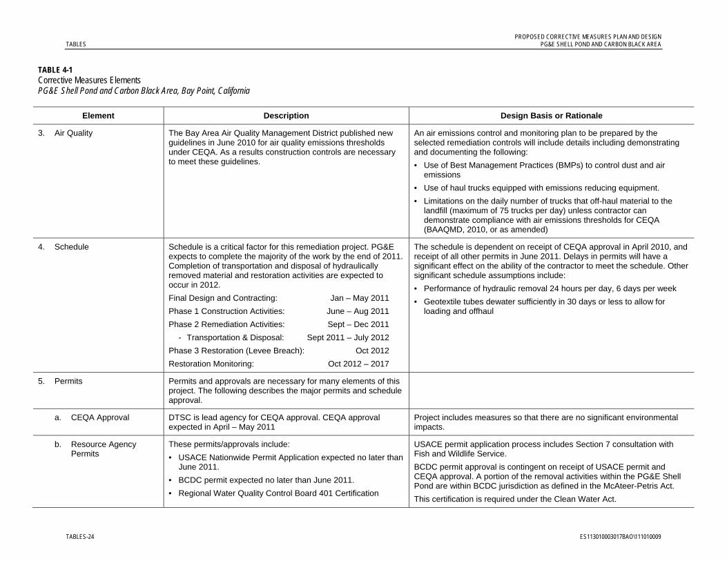
PROPOSED CORRECTIVE MEASURES PLAN AND DESIGN TABLES PG&E SHELL POND AND CARBON BLACK AREA
TABLES-24 ES113010003017BAO\111010009
TABLE 4-1 Corrective Measures Elements PG&E Shell Pond and Carbon Black Area, Bay Point, California
Element Description Design Basis or Rationale
3. Air Quality The Bay Area Air Quality Management District published new guidelines in June 2010 for air quality emissions thresholds under CEQA. As a results construction controls are necessary to meet these guidelines.
An air emissions control and monitoring plan to be prepared by the selected remediation controls will include details including demonstrating and documenting the following:
• Use of Best Management Practices (BMPs) to control dust and air emissions
• Use of haul trucks equipped with emissions reducing equipment.
• Limitations on the daily number of trucks that off-haul material to the landfill (maximum of 75 trucks per day) unless contractor can demonstrate compliance with air emissions thresholds for CEQA (BAAQMD, 2010, or as amended)
4. Schedule Schedule is a critical factor for this remediation project. PG&E expects to complete the majority of the work by the end of 2011. Completion of transportation and disposal of hydraulically removed material and restoration activities are expected to occur in 2012.
Final Design and Contracting: Jan – May 2011
Phase 1 Construction Activities: June – Aug 2011
Phase 2 Remediation Activities: Sept – Dec 2011
- Transportation & Disposal: Sept 2011 – July 2012
Phase 3 Restoration (Levee Breach): Oct 2012
Restoration Monitoring: Oct 2012 – 2017
The schedule is dependent on receipt of CEQA approval in April 2010, and receipt of all other permits in June 2011. Delays in permits will have a significant effect on the ability of the contractor to meet the schedule. Other significant schedule assumptions include:
• Performance of hydraulic removal 24 hours per day, 6 days per week
• Geotextile tubes dewater sufficiently in 30 days or less to allow for loading and offhaul
5. Permits Permits and approvals are necessary for many elements of this project. The following describes the major permits and schedule approval.
a. CEQA Approval DTSC is lead agency for CEQA approval. CEQA approval expected in April – May 2011
Project includes measures so that there are no significant environmental impacts.
b. Resource Agency Permits
These permits/approvals include:
• USACE Nationwide Permit Application expected no later than June 2011.
• BCDC permit expected no later than June 2011.
• Regional Water Quality Control Board 401 Certification
USACE permit application process includes Section 7 consultation with Fish and Wildlife Service.
BCDC permit approval is contingent on receipt of USACE permit and CEQA approval. A portion of the removal activities within the PG&E Shell Pond are within BCDC jurisdiction as defined in the McAteer-Petris Act.
This certification is required under the Clean Water Act.

PROPOSED CORRECTIVE MEASURES PLAN AND DESIGN PG&E SHELL POND AND CARBON BLACK AREA TABLES
ES113010003017BAO\111010009 TABLES-25
TABLE 4-1 Corrective Measures Elements PG&E Shell Pond and Carbon Black Area, Bay Point, California
Element Description Design Basis or Rationale
c. Local County Permits County permits for construction activities include grading and construction permits. These permits are to be obtained by the construction contractor.
County permits will require demonstration of CEQA approval.
6. Documentation Reports are required by the lead agency and as part of permit conditions. The following are the key reports for this project.
a. Remediation Completion Report
This report is required by DTSC to document the activities and results of the remediation activity. The expected submittal date of this report is March 2012.
Report will include description of removal activities, confirmation sampling and analyses results, and upcoming planned activities to complete restoration.
b. Final Restoration Plan This report is primarily for the resource agencies and will present the post-removal elevations and the final hydrologic analysis to support the levee breaching and pond restoration activities. The expected submittal date of this report is April 2012.
This report will describe any modifications to the initial conceptual restoration plan for the PG&E Shell Pond. This plan will also incorporate any permit conditions and any water treatment that may be needed prior to levee breaching.
c. Restoration Completion Report
This report will document the Phase 3 Restoration Activities. The expected submittal date of this report is December 2012.
Report will include description of levee breaching and final restoration activities including removal of material-handling area.
Notes:
1. The summary of design elements is based on preliminary design drawings provided in Appendix A of this report. Some changes to the current plans are anticipated as part of the final design. Additional design details will also be provided as part of the final design.
2. The project controls and protection measures will be revised based on additional biological surveys currently underway and in accordance with resource permit conditions.
3. The contractor or PG&E consultant will also be required to submit project plans (for example, Health and Safety, Air Emissions Control Plan, Stormwater Pollution Prevention Plan) prior to construction.


PROPOSED CORRECTIVE MEASURES PLAN AND DESIGN PG&E SHELL POND AND CARBON BLACK AREA TABLES
ES113010003017BAO\111010009 TABLES-27
TABLE 4-2 Plans in Support of the PG&E Shell Pond Corrective Measures Implementation PG&E Shell Pond and Carbon Black Area, Bay Point, California
Plan Phase 1 Phase 2 Phase 3
Traffic Control and Waste Transportation Plan
For the transport of equipment and materials to the site for construction of the access road and material-handling area
For the transport of soil and dewatered non-native material (NNM) to an offsite Class II landfill
Soil from levee breaching will remain onsite, however construction equipment will travel to the site
Health and Safety Plan
For worker health and safety involving construction equipment and non-hazardous materials
For worker health and safety involving construction equipment used over water, on levees, or during transport of material on- and offsite
For worker health and safety involving construction equipment and non-hazardous materials
Emergency Response Plan (Included in Health and Safety Plan)
Addresses emergencies that could arise during construction of access road and material management areas
Addresses emergencies that could arise during material removal and offsite transport and disposal, such as local events (for example, fire or traffic accidents) that could affect movement to and from the site
Addresses emergencies that could arise during levee breaching
Stormwater Pollution Prevention Plan
Addresses stormwater runoff control during all construction activities
Addresses stormwater runoff control during all construction activities
Addresses stormwater runoff control during all construction activities
Air Quality Management Plan
To monitor and mitigate equipment emissions and dust during all construction activities
To monitor and mitigate equipment emissions and dust during all construction activities
To monitor and mitigate equipment emissions and dust during all construction activities
Waste and Water Management Plan
Not applicable To monitor waste material leaving the site, and water generated during the removal action; includes criteria for determining treatment of water remaining in the pond after NNM removal
To test water quality in the east slough and the pond to determine whether treatment is required before breaching the levee
Sampling and Analysis Plan
Not applicable To verify that target remediation goals are met for material remaining in the pond and former wastewater discharge ditch
To verify that material being disposed meets landfill acceptance criteria
To test geotube filtrate recycled to the pond
To test water quality in the east slough and the pond to determine whether treatment is required before breaching the levee

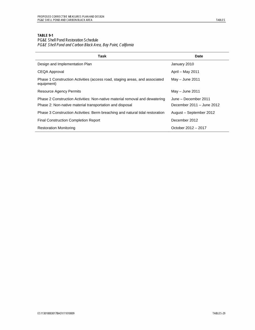
PROPOSED CORRECTIVE MEASURES PLAN AND DESIGN PG&E SHELL POND AND CARBON BLACK AREA TABLES
ES113010003017BAO\111010009 TABLES-29
TABLE 9-1 PG&E Shell Pond Restoration Schedule PG&E Shell Pond and Carbon Black Area, Bay Point, California
Task Date
Design and Implementation Plan January 2010
CEQA Approval April – May 2011
Phase 1 Construction Activities (access road, staging areas, and associated equipment)
May – June 2011
Resource Agency Permits May – June 2011
Phase 2 Construction Activities: Non-native material removal and dewatering
Phase 2: Non-native material transportation and disposal
June – December 2011
December 2011 – June 2012
Phase 3 Construction Activities: Berm breaching and natural tidal restoration August – September 2012
Final Construction Completion Report December 2012
Restoration Monitoring October 2012 – 2017


Figures

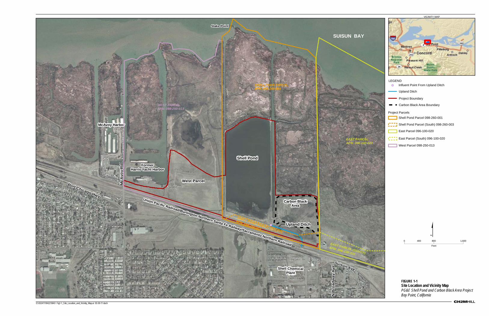
VICINITY MAP
!(
Shell Pond
Carbon BlackArea
McAvoy Harbor
Shell ChemicalPlant
Mc
Av
oy
Rd
Port Chicago Hwy
N B
roa
dw
ay
Av
e
Suisun Ave
Stake Point
SUISUN BAY
0 800 1,600400
Feet
LEGEND
!(
$
ES032411184221BAO Fig1-1_Site_Location_and_Vicinity_Map.ai 03-30-11 dash
Upland Ditch
Project Boundary
Carbon Black Area Boundary
Influent Point From Upland Ditch
Union Pacific Railroad/Burlington Northern Santa Fe Railway/Sacramento Northern Railroad
Union Pacific Railroad/Burlington Northern Santa Fe Railway/Sacramento Northern Railroad
Union Pacific Railroad/Burlington Northern Santa Fe Railway/Sacramento Northern Railroad
FormerHarris Yacht Harbor
FormerHarris Yacht Harbor
FIGURE 1-1 Site Location and Vicinity MapPG&E Shell Pond and Carbon Black Area ProjectBay Point, California
West ParcelWest ParcelWest Parcel
Upland DitchUpland Ditch
SHELL P ND PARCEL
EAST PARCELAPN: 096-100-020
EAST PARCEL (SOUTH)APN: 096-100-020
APN 09 -260 001O
8 -:
WEST PARCELAPN: 098-250-013
SHELL PAPN: OND P 098-260 ARC-003 EL (SO HUT )
Shell Pond Parcel 098-260-001
East Parcel 096-100-020
East Parcel (South) 096-100-020
West Parcel 098-250-013
Shell Pond Parcel (South) 098-260-003
Project Parcels

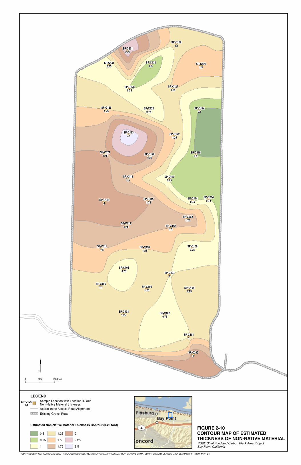
�)
�)�)
�)�)�)
�)
�)
�)�)�)
�)�)
�)�)�)
�)�)
�)�)
�)
�)�)
�)�)�)
�)�)
�)�)�)
�)
�)
�)
�)
�)
SP-C101
1
SP-C102
0.75
SP-C103
1.25
SP-C104
1.25
SP-C105
1.25
SP-C106
1.1
SP-C107
1
SP-C108
0.75
SP-C109
0.75SP-C110
1.25
SP-C111
1.5
SP-C112
1.5
SP-C113
1.75
SP-C114
0.75
SP-C115
1.75SP-C116
2
SP-C117
0.75
SP-C118
1.5
SP-C119
0.5SP-C120
1.75
SP-C121
1.75
SP-C122
1.25
SP-C123
2.5
SP-C124
0.5
SP-C125
0.75
SP-C126
1.25
SP-C127
1.25
SP-C128
0.75
SP-C129
1.5
SP-C130
0.5
SP-C131
0.75
SP-C132
1.1
SP-C201
2.25
SP-C202
1.75
SP-C203
2
SP-C204
0.75
LEGEND
�)Sample Location with Location ID andNon-Native Material thickness
Approximate Access Road Alignment
Existing Gravel Road
FIGURE 2-10CONTOUR MAP OF ESTIMATED THICKNESS OF NON-NATIVE MATERIAL
0 250125 Feet
$
PG&E Shell Pond and Carbon Black Area ProjectBay Point, California
0.5
0.75
1
1.25
1.5
1.75
2
2.25
2.5
Estimated Non-Native Material Thickness Contour (0.25 foot)
SP-C1061.1
\\ZINFANDEL\PROJ\PACIFICGASELECTRICCO\393468SHELLPNDMNITOR\GIS\MAPFILES\CARBON BLACK\ESTIMATEDMATERIALTHICKNESS.MXD JLAMANTI 4/11/2011 11:41:24


EastSlough
WestSlough
Former Harris Yacht HarborFormer Harris Yacht Harbor
\\ZINFANDEL\PROJ\PACIFICGASELECTRICCO\393468SHELLPNDMNITOR\GIS\MAPFILES\WETLANDDELINEATION\PROPOSED_PROJECT_ELEMENTS.MXD CARCHER 10/18/2010 14:23:51
Legend
Project Area
Limits of Construction
100-Foot Wetland Buffer Zone
Approximate Mechanical Excavation Area
Approximate Hydraulic Excavation Area
Hydraulic Containment Materialand Construction Staging Area
Proposed Access Road
Potential Rail Nesting Buffer (February- August)
Wetland Areas for Seed Only
Carbon Black Area Boundary
Bare Areas for Fill (1 foot) and Seed
Existing Gravel Road
Wetlands and Waters
Section 404 Waters of U.S.
000,10 teeF005
Union Pacific Railroad / Burlington Northern Santa Fe Railway / Sacramento Northern Railroad
Union Pacific Railroad / Burlington Northern Santa Fe Railway / Sacramento Northern Railroad
FIGURE 4-1 Proposed Project ElementsPG&E Shell Pond and Carbon Black Area ProjectBay Point, California
West Parcel
Former Wastewater Former Wastewater Discharge DDischarge Ditch
Former Wastewater Discharge Ditch
Material Handling Area
Gravel Access Road
Temporary Access Bridge
3A
2E
2A 2C 2D
2F
2B
1B
1A
1
2
3
1A
Shell Pond
Phase 1A – Access RoadB – Material Handling Area
Phase 2A – Non-Native Material Removal in Shell PondB – Wastewater Ditch Soil RemovalC – Water ManagementD – Confirmation SamplingE – Transportation and DisposalF – Carbon Black Area Fill/Reseeding
Phase 3A – Breach Berm
ES032411184221BAO Fig4-1 proposed project elements_v2.ai 03-30-11
Carbon Black AreaCarbon Black Area
Channelized Tributaryto West Slough
Channelized Tributaryto West Slough

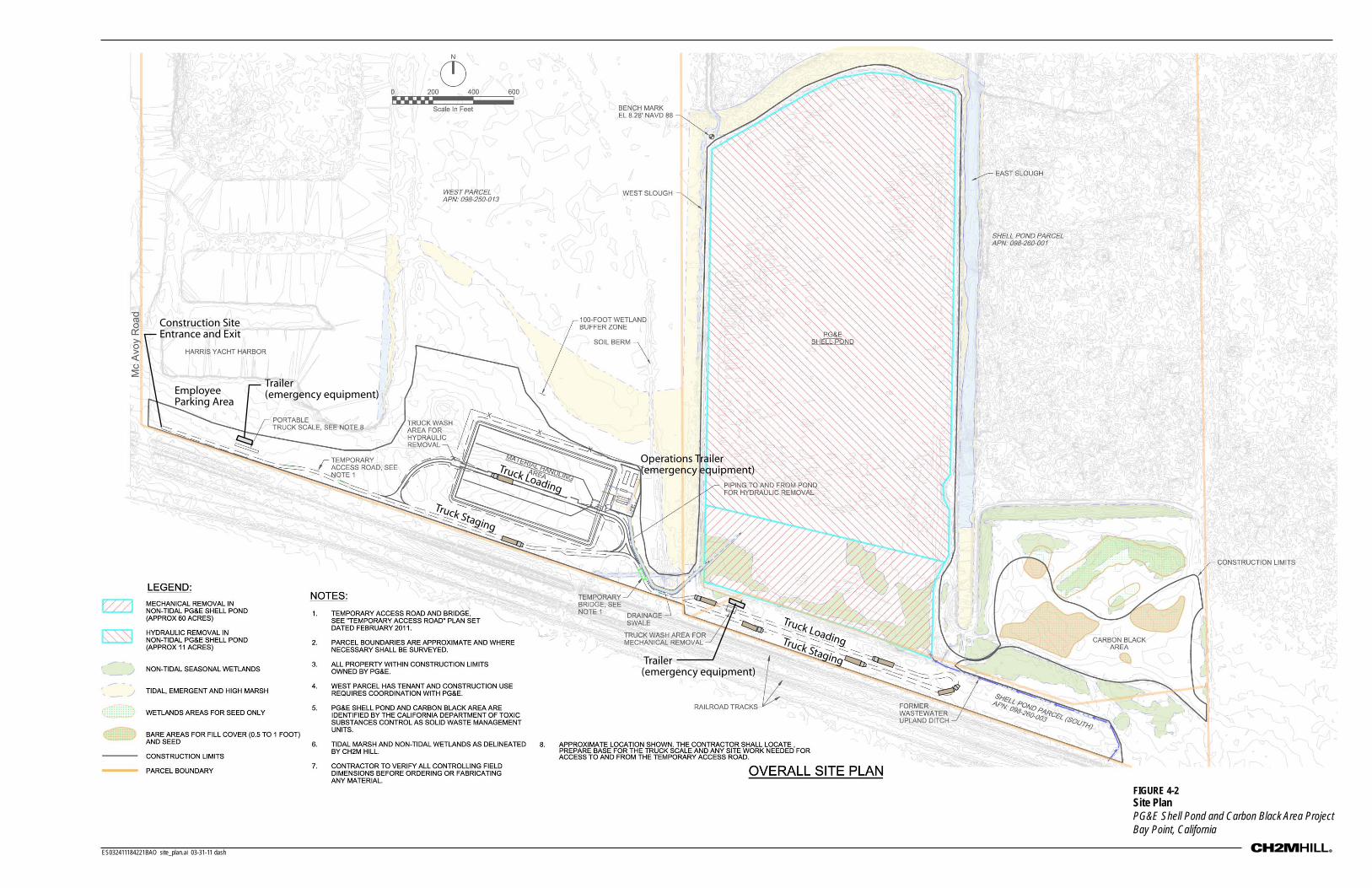
ES032411184221BAO site_plan.ai 03-31-11 dash
FIGURE 4-2 Site PlanPG&E Shell Pond and Carbon Black Area ProjectBay Point, California
Construction Site Entrance and Exit
Truck Loading
Truck Loading
Truck Staging
Truck Staging
Employee Parking Area
Trailer (emergency equipment)
Operations Trailer (emergency equipment)
Trailer (emergency equipment)


FIGURE 4-3Wetland and Unvegetated Portions of Carbon Black Area
7
6
6
7
7
6
6
7
7
8
7
8
9
9
8
10
11
11
10
9
9
789
1010 10
11
8
9
9
10
9
8 9
8
8
8
8
8
9
106
56
6
6 7
5
7
6
4
5
5
8
9
9
9
8
7
5
6
89
3
4
3
12
12
11
10
9
8
6
SW-14
0.35 Acres
1.9 Acres
0.2 Acres
0.65 Acres
1.57 Acres
0.05 Acres
SW-5
SW-4
SW-13
SW-6
SW-7
SW-10
SW-11
SW-12
SW-2
SW-9
SW-8
Upland Ditch
SWL-2
SWL-3
0 10050
Feet
LegendProject Area
Wetlands and Waters
Shell Pond
Seasonal Wetland
Tidal Slough
Swale (SWL)
Upland Ditch
Emergent Marsh (EM)
\\ZINFANDEL\PROJ\PACIFICGASELECTRICCO\393468SHELLPNDMNITOR\GIS\MAPFILES\WETLANDDELINEATION\CBA_EXCAVATION.MXD JLAMANTI 10/14/2010 15:03:22
ALT 1 UPLANDS ONLY IMPACT:Approximately 3-4 acres
ALT 2 UPLAND FILL WITH WETLAND SEEDING IMPACT:Approximately 3 to 4 acres in uplands; no permanent impactin wetlands
ALT 3 UPLAND AND WETLAND FILL:Approximately 5 to 6 acres including approximately 2 acres in wetlands
Elevation Contours (NAVD 88)
5 ft Interval
O
Carbon Black Area Boundary
ther Interval
Approximate Boundary of Major Unvegetated Areas (~5 acres)
PG&E Shell Pond and Carbon Black Area ProjectBay Point, California
ES032411184221BAO wetland_unvegetated_area.ai 03-30-11 dash


ES032411184221BAO ConceptSection_LeveeBreach.ai 04-11-11 dash
WEST
CROSS SECTION PERPENDICULAR TO EXISTING LEVEE
EAST
NORTH
NOT TO SCALE
SOUTH
15 ftvaries
Elev. ~5ft
Elev. ~2 to 3ft
~ 90 ft varies
slopes varies
EXISTINGLEVEE
FILL
EXISTINGLEVEE
FILL
EXISTINGLEVEE
NORTH AND SOUTH
OF BREACH
EASTSLOUGH
EASTSLOUGH
TOP OF EXISTING LEVEE8.5 to 9.5 ft varies
EXISTING GRADE8.5 to 9.5 ft
HTL 7ft
~ 82 ft
EL. 2.5 to 3 ft
riprap
non-native material to be removed
11
2
1
3
1
3
1
6
6
Proposedbreach
Potential placement of levee breach soil
OPTIONAL
to be determined
CROSS SECTION CENTER LINE OF LEVEE
CROSS SECTION NORTH AND SOUTH OF PROPOSED BREACH
EL. ~2 to 3 ft
FIGURE 4-4 Conceptual SectionsProposed Levee BreachPG&E Shell Pond and Carbon Black Area ProjectBay Point, California


ID Task Name
1 PERMITS2 CEQA Process Complete3 All other Permits Necessary for Hydraulic Removal Actions4 USACE 404 Permit approved5 RWQCB WQ Certification approved6 CDFG Permits approved7 BCDC Permit approved8 Contra Costa Grading Permit in Hand9 Spring 2011 Sensitive Species Blackout Period
10 Spring 2012 Sensitive Species Blackout Period11 CMIP17 DESIGN23 PROCUREMENT25 PRE REMOVAL ACTIVITIES26 Mobilization & Submittals - Road and Receiving Area27 Precharacterize Non-Native Material for Direct Load Landfill Acce28 Construct Access Road29 Construct Containment/Dewatering Area30 Place Import (from Containment/Dewatering Area) in Carbon Blac31 Revegetate Carbon Black Area with Native Grasses32 Excavate and Stockpile Former Wastewater Ditch33 Load/T&D Former Wastewater Ditch Material to Keller Cyn.34 MECHANICAL REMOVAL ACTIVITIES35 Excavate/Load/T&D Mtl to Keller Cyn (600 cy/shift)36 Demobilize Mechanical Removal Operation37 HYDRAULIC REMOVAL ACTIVITIES38 Mobilize Dredge Equipment, Construct Conveyance/Ammendme39 Hydraulic Excavation to Geotubes (3k yd/24-hr day)40 Perform confirmation sampling/analysis41 Re-Excavate as Necessary (Based on Sample Results)42 Final Confirmation Sampling43 Characterize Non-Native Material for Landfill Acceptance44 Load/Stabilize/T&D Material to Keller Cyn45 Demobilize Hydraulic Removal Operation46 POST REMOVAL ACTIVITIES47 Removal of Receiving & Transfer Areas & Restoration48 Pond Area Restoration49 Pond Water Sampling50 Breach Berm
4/156/16/16/16/16/16/1
Nov Dec Jan Feb Mar Apr May Jun Jul Aug Sep Oct Nov Dec Jan Feb Mar Apr May Jun Jul Aug Sep Octuarter 1st Quarter 2nd Quarter 3rd Quarter 4th Quarter 1st Quarter 2nd Quarter 3rd Quarter 4th Q
2011 2012
Task
Split
Progress
Milestone
Summary
Project Summary
External Tasks
External Milestone
Deadline
ES032411184221BAO corr_action_schedule.ai 04-11-11 dash
FIGURE 9-1 Shell Pond Corrective Action Implementation SchedulePG&E Shell Pond and Carbon Black AreaBay Point, California
