proposal/sub contract for production …lss.fnal.gov/archive/other/ssc/ssc-pc-028.pdfpart, to any...
TRANSCRIPT

ISNANOPTICSD1cXfl¼ThD
PROPOSAL/SUB CONTRACT
FOR
.
UNIVERSITY OP nnRmA.Rcsearct &Tcthnology ParkOneProps Bculevan B 37
- AIua, FIaida 32615Pbonc 904-462.2094
Pat 904-462-3932
PRODUCTION OF RADIATION
HARD SCINTILLATOR
Prepared for:
Superconducting Super CoHider
Dallas, Texas
October 1, 1989

NANOPTIC SNcoIroRMn
UNIVERSITYOFFLORIDAResearch& TechnologyParkOne ?ICw..u.. Boulevard,B 37
- .tn Florida. 32615Thoac 904-462-2094F 904-442-3932
Statement of Confidentiality
This proposal includes confidential and/or proprietary drawings, specifications and other Datacollectively the "Data". DOE will not duplicate, use, or disclose the Data, in whole or inpart, to any person, firm, or corporation, other than DOE employees, and then only to suchlimited emp’oyees as are required to evaluate this proposal. Nanoptics, Inc., retains allownership of and any copyright, patent or intellectual property rights in, the Data, and DOEobtains no rights of any kind in the Data whether by the submission of this proposal orotherwise. DOE, upon Nanoptics’ request, or upon completion of its evaluation, shall returnto Nanoptics the proposal/quotation and all Data related thereto and any copies thereof. Ifa contract is awarded to Nanoptics as the result of or in connection with this proposal, DOEshalt have the right to duplicate, use of, disclose the Data to the extent provided in theresulting contract.
TABLE OF CONTENTS
1. Introduction - . . . . - 3
2. Properties of Sitoxane Scintillator . . . . . 4
3. Processing of Polysiloxane Gel Scintillator Material - . . . 9
4. Cladding Materials - . . . . . . . 10
5. Proposed Equipment - . . . . . . 11
6. Objectives of the Proposed Research . . . . . . 14
7. Work Plan and Milestones. - . . . . . . 16
8. Budget . . - . . . . . . 17-18
9. Budget Justification - . - . - . . . 19
10. Personnel . . - . . . . . 20
11. Bibliography - - . . . . . . . . 31
12. Figures . . . . - - . . . . 32-37
13. Appendix I - Description of Nanoptics - . . . - . 38
14. Appendix II - Hills R & D Inc., Fiber Spinning Equipment . . . 41
15. Appendix III - Killion, Coextrusion Film Plate Equipment . . . 48
Abstract
The Department of Energy has funded about twelve man years of effort at the
University of Florida to create a plastic scintitlator with properties similar to previous
material, but with for a factor of one hundred greater resistance to optical degradation by
nuclear radiation. This project has been successful and the precise conditions for
producing the material are known. The University of Florida has applied for worldwide
patent protection for this invention.
Nanoptics, Inc., has negotiated an exclusive license with the University of Florida
to commercialize the invention. It is now necessary to process this material Into the forms
of clad fibers and plates suitable for use at the SSC. The purpose of this proposal to the
SSC is for Nanoptics, Inc., to acquire the equipment for material processing. We are
requesting the smallest scale research type extrusion equipment which is commercially
produced. From the time of ordering, it will take 6-8 months for manufacture and delivery
of the equipment. Given the short time scale for SSC detector development before
designs will be frozen, ft is essential that material processing equipment be acquired as
soon as possible.
Personnel in, or consulting with Nanoptics, Inc., have over thirty man years of
experience in fiber production. The SSC has great need of this material, we know how
to make the material, we have the expertise to process the material, we request support
for the equipment to process the material into the form required for the SSC.
Finally, given the financial and manpower investment in this project up to this point
in time, it is economically important to ensure the retention of the full scale
commercialization of this high technology within the USA. We request full support for
Nanoptics, Inc., in this challenging technical development which is important to the full
exploitation of the SSC.
2

1. Introduction
There is great interest by a number of collaborations in the use of plastic scintillator
as the active medium of choice for particle detection at the SSC. This Is evidenced by
the large number of major subsystem proposals utilizing plastic scintillator for either
calorimetry or particle tracking.
It is well known that the radiation hardness of conventional polystyrene PS or
polyvinyltoluene PVT based scintitlator is inadequate for the desired levels of stability
over a typical ten year utilization period in the anticipated radiation fields at the SSC.
Much of the recent interest in the use of plastic scintillator at the SSC has been
stimulated by the discovery at the University of Florida that potysiloxane based scintillators
offer an approximate one hundred fold improvement in resistance to radiation degradation
compared to conventional scintiltator at a given wavelength of emitted light. This new
scintitlator promises to offer the desirable features of conventional plastic scintillator
coupled with this remarkable improvement in radiation stability. Primary and secondary
fluors have been chosen for the new siloxane scintillator and work is continuing on a
systematic investigation of the optimum fluors to be used in the case of wavelength
shifting materials. This work is being done at the University of Florida.
An SSC calorimeter detector will require approximately 10’ meters of fiber in one
design, and 10 plates in another. A third design requires a mixture of plates and fibers.
In each case, the quantity of fiber and/or plate is so great that it demands extrusion
processing technology for the plastic scintillator production. We anticipate that siloxane
scintillator for calorimeters wilt most economically be produced using thermoset siloxane.
The purpose of this proposal is to support Nanoptics, Inc., to develop the production
capacity for thermoset siloxane suitable for prototype subsystem calorimetry at the SSC.
A synopsis of a description of Nanoptics, Inc., is given in Appendix I. To meet the time
3

scale which has been established for SSC detector prototype research, and detector
proposal submission, it is essential for Nanoptics, Inc., to initiate development of the
thermoset siloxane production technotogy at this time. There is a 6-8 mOnth lead time
for extrusion equipment delivery.
Nanoptics, Inc., is funded through a Small Business Innovation Research grant from
the DOE to develop the first thermoplastic siloxane. This plastic will be particularly suited
to the micro-fibers required for particle tracking. Coherent bundles of these micro-fibers
will be produced for this purpose. This proposal does not address that processing
technology. Nanoptics, Inc., received a second SBIR, from the National Science
Foundation, to study deterioration of siloxane and ftuors by UV radiation and high
temperatures.
2. Properties of Siloxane Scintillator
a Plastic Transmission and Radiation Hardness
Work at the University of Florida has resulted in the identification of the most
nadiation hard optically transparent polymers known to this date, polyorganosiloxanes.
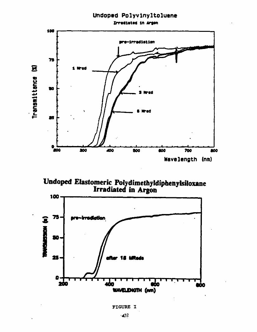
There is c< 1% transmission loss in 1.5 cm samples at 450 nm after exposure to 18
Mrads in Argon The radiation resistance is slightly better in Argon than in air. This is
depicted in Figure I where polydimethyldiphenylsiloxane is compared to polyvinyltoluene,
a widely used commercially available scintillator base. Polyvinyltoluene exhibits significant
absorption at wavelengths greater than 600 nm after exposure to 1 Mrad. This is true
whether samples are exposed in Argon or in air.
The development of color centers or yellowing in plastics with time is also a welt
known characteristic. This property is prevalent in polystyrene, polyvinyltoluene and
platinum cured polydiorganosiloxanes. The High Energy Physics group at the University
4

of Florida has conducted extensive research in this area In addition, Nanoptics, Inc.,
received an SBIR from the NSF to study UV and high temperature induced yellowing of
polysiloxane. It now appears evident that polyorganosiloxane samples cured with peroxide
rather than platinum exhibit an undetectable tendency to "yellow" with time and are very
resistant to temperature induced yellowing. In these respects the material is at least as
good as the conventional plastics.
The chemistry involved in the peroxide cure reaction is:
B3C?_I_fi-O F-1-y-°uI 12111013 013H
PaSde - -- SI03=013 + S1013
A specific peroxide cure agent has been identified for use in this reaction:
5
It appears that peroxide cured polydimethyldiphenysiloxanes will withstand high
radiation doses and resist "yellowing" with time.
b Plastic and Primary Fluor
In addition to plastic scintillator base research, the High Energy Physics group at
the University of Florida has identified radiation hard primary fluors. They have
demonstrated that appropriate quaterphenyls dissolved in polydiorganosiloxane have high
quantum efficiencies, nsec decay times, and c 10% loss of light output after an
irradiation of io Rads.
These "appropriate" quaterphenyls were identified by analyzing the mechanism of
radiation induced decrease in light transmission in oligophenylene/siloxane based
scintillator. The problem was to identify, fluor substituents which enhance Solubility but
are not labile to radiation. That is, some bulky, solubitity enhancing substituents react
under irradiation to produce color centers. Ught output reduction is not the result of
damage to the oligophenylene fluor but rather to the solubility enhancing substituents.
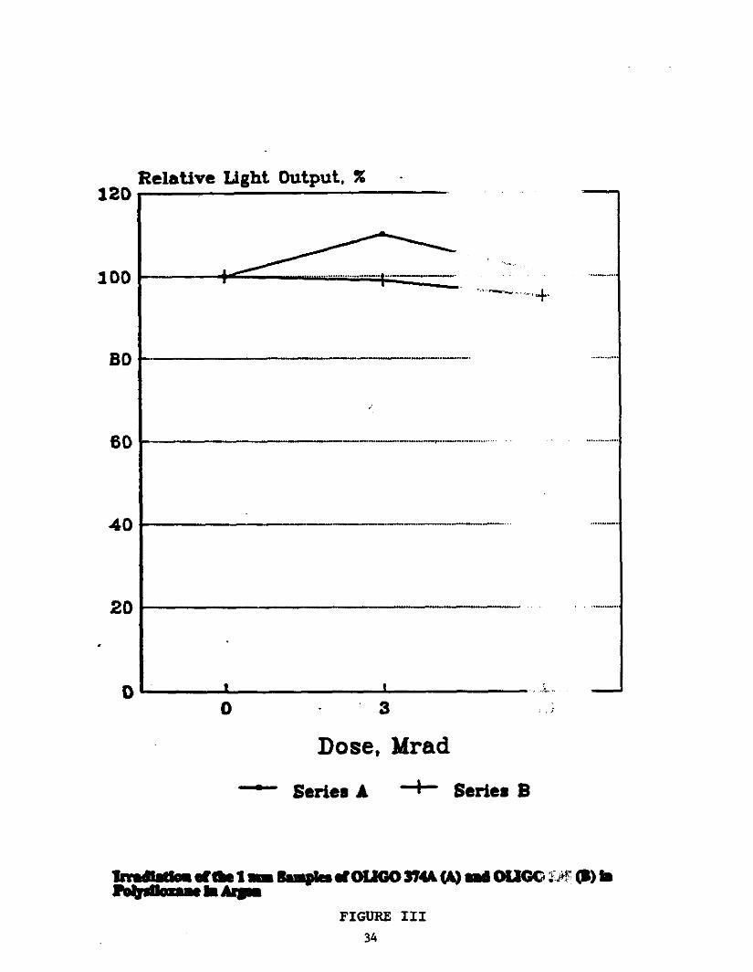
See Figure II. Thin samples showed no significant light output loss after 10 Mrad
exposure, meaning that there is negligible loss due to chromophore degradation Figure
III. In thick samples light output decrease correlates with optical density increase at the
emission maximum Figure IV. In all cases, increasing the complexity of substituents
leads to increasing color center formation which is the main source of optical damage to
the scintillator.
The High Energy Physics group is currently testing oligophenylene dyes made
soluble with t-butyl groups. These dyes have shown the greatest photostability to date
in quaterphenyl laser dye operation. When pumped by a xenon chloride eximer laser
these dyes were six times more stable than previously tested dyes 1. T-butyl groups
6

impede degradation reactions by sterically hindering the approach of adjacent molecules
to the chromophore 2.
In the polysiloxane system, t-butyl fluor substituents are expected to
a increase solubility
b decrease reactivity
c impede fluor migration
In reference to c long term migration of fluors to the siloxane surface has been observed
in some cases 3, 4. We have decided on the chemical route to covalently bond the
fluors to the polymer if this turns out to be a problem. Accelerated aging studies are
underway to quantify the effect.
c Secondary Dye Work
In order to take full advantage of the polysiloxane-based scintillators one must shift
the primary dye emission wavelength to greater than or equal to 450 nm, where
polysiloxane does not experience any transmission loss after 18 Mrad irradiation dose in
Argon. This has now been accomplished by using a secondary dye in combination with
the primary fluor, as a wavelength shifter. Much work in the last year has gone into
secondary dye synthesis, characterization and testing.
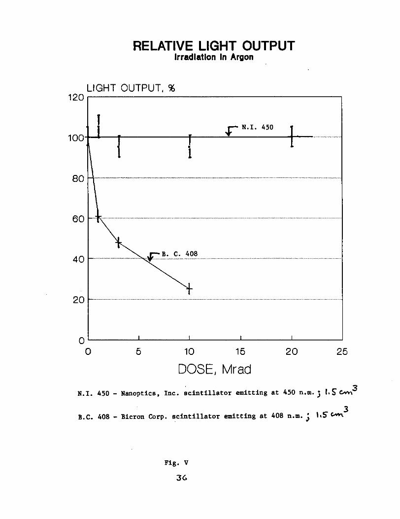
Three classes of wavelength shifter dyes have been investigated. The stability of
the best combination of plastic and dyes is shown in Figure V. This new plastic
scintillator has about one hundred times the resistance to degradation by nuclear radiation
compared with the standard commercial product, Bicron 408 which does emit at a slightly
shorter wavelength. As well as the usual properties of high quantum efficiency, radiation
hardness, and short fluorescence time an additional property is highly desirable for a
secondary fluor. This is the property of a low self reabsorption at a wavelength
7
corresponding to the peak emission of the dye. Since, the light attenuation of a plastic
scintillator is usually determined by this parameter, considerable effort has been expended
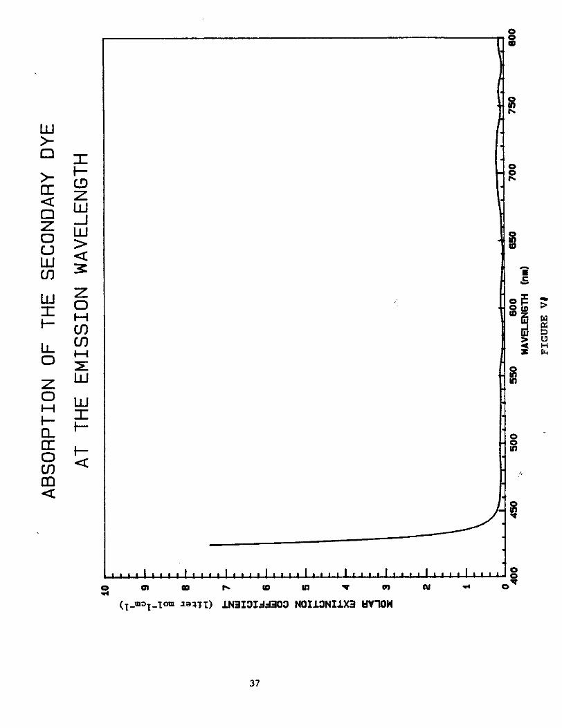
to achieve a low molar extinction coefficient at 450 nm for the secondary dye which we
identify as N.I.s.d.450c. Figure VII shows the molar extinction coefficient in this
wavelength range. The ratio of the extinction coefficient at 450 nm to the extinction
coefficient at peak absorption at 370 nm is io. This is a remarkably low ratio. It is
about 100 times better than POPOP and is comparable to the value measured with a
proton transfer dye such as 3HF which has very large Stokes shift. In the case of this
secondary dye, the low ration comes not from an intrinsically large Stokes shift, but from
the detailed dynamics of the molecular transitions undergone by the dye.
The extremely low reabsorption by the dye makes ft’s use in fibers particularly
attractive. In fact, the reflection coefficient between the core and cladding will probably
dominate the attenuation of the 450 nm light in fibers. A preliminary measurement of
attenuation of scintillation light in a 25 cm long strip with 10 mm X 2 mm cross section
gave an attenuation length 75 cms. It is now of great importance to address the
processing of the scintillator material into fibers and plates possibly clad as well to
achieve the optimum processing conditions for maximum internal reflection coefficient.
d Siloxane Physical Properties
Nanoptics will use vinyl terminated high molecular weight
polydimethyldiphenylsiloxane gel for splnning 1 mm clad fibers and for scintillator plates.
The structure of this peroxide cure, gel siloxane depicted earlier has advantages over
platinum cure systems. These are:
1 "Yellowing" with time is not observed.
8
2 Platinum cure systems react with proton transfer dyes 3-HF and
eliminate fluorescence. Peroxide cure systems do not interfere with
tautomeric fluorescence. -
3 The peroxide cure gels cure to a shore A hardness of 70. The
surface is not tacky, whereas platinum cure systems cure to a
hardness of 8-20 and are tacky 5.
4 In order to reaction spin coextruded fibers, a high viscosity core
material is needed. The high molecular weight gel selected has a
viscosity of 200,000 cps at room temperature. This is discussed more
completely in the next section.
5 Commercially available methyvphenyl siloxane gels are used widely
as high performance elastomers. These materials are optically
transparent. Because of their wide use, the cost is significantly less
than for platinum cured gels.
3 Processing of Polysiloxane Gel Scintillator Material
The siloxane gel cures is transformed into a material which does not flow by
crosslinking. After crosslinking the material is not thermally processible. To meet the
needs of SSC detectors we propose to reaction spin clad fibers and to reaction extrude
clad plates. We make note of three significant facts:
a Reaction spinning of other polymers including crosslinked
polyurethane has been developed 6,7.
b The literature cites a patent on the production of clad, cured, cross-
linked siloxane fibers 8.
c Armet Industries Inc. produces extruded, crosslinked siloxane tubes.
9

In addition, every expert we have consulted is confident the process will work. The
peroxide catalyst and siloxane will be mixed in a roll mill. The extruder will convey this
material to a spinnerette head for fibers or to a film/sheet die. The material must solidify
or cure after exit from the head or die. In the spinnerette head or plate die, the material
will be encased in a thermoplastic meltable fluorocarbon. These fluorocarbons solidify
rapidly upon exit from the extruder. They act as bottles encasing the catalyzed siloxane
which will be cured after the encasement process. Cure will take place at a temperature
below the melting point of the cladding. We have already shown that the siloxane
completely cures at temperatures as low as 100°C. This is below the melting point of the
cladding materials. See next section.
4. Cladding Materials
The High Energy Physics Group at U of F has identified optimum fluorocarbon
cladding materials. These are: Kynar 7201, Kynar 9301 and Kynar 2801. Two
properties are of utmost importance in reaction processing:
a Thermal properties - processing temperature
b Optical properties - refractive index.
The following table summarizes these properties and is discussed below. PVDF, a
commonly used fluoropolymer for cladding glass fibers is included for comparison:
Processing ‘H. ScTemperature
KYNAR 7201 120°C 141 164KYNAR 9301 110°C 1.40 17.8KYNAR 2811 140°C 1.41 16.4PVDF > 170°C 142 15.0SILOXANE GEL 1 00°CReaction 1.47
Temperature
10
Thermal properties of the siloxane dictate the choice of cladding materials. The
peroxide catalyzed system reacts at temperatures 100°C. However, It must react after
exit from the extruder. The extruder throughout is 12 lbs.ihour. The average residence
time of the material in the heated extruder is 3 minutes. At temperatures below 160°C
the siloxane cure time is much longer than 3 minutes. The three Kynars listed have ideal
thermal properties for reaction extrusion. In addition, the fluors are not thermally degraded
at these temperatures. Fluoropolymers commonly used to clad glass fibers are processed
at temperatures from 180-260°C. At these temperatures the fluors would degrade and the
siloxane would crosslink in the extruder.
In order to ensure good light pipe trapping, the refractive index of the cladding
material must be lower than that of the core. Optimum efficiency of light pipe trapping
is obtained at confinement angles of 8° or higher 9. The confinement angle is defined
as:
= 90° - Arc Sin S cladding/S core
The above table illustrates that the selected cladding materials have ideal optical and
thermal properties for processing our scintillator material.
5. Proposed Equipment
We propose to purchase equipment to produce clad fibers and clad scintillator
plates. The same up stream compounding, feeding and extrusion conveying equipment
will be used for both plates and fibers.
The equipment consists of 5 subsystems:
a A Two Roll Mill compounder for mixing dye and peroxide with the gel,
$10,000.
11
b A Ram feeder to feed the gel Into the gel extruder. A conventional
chip to hopper to feed the cladding pellets into the cladding extruder,
$2,000. -
c Two one inch diameter single screw extruders with three heating
zones and 3HP Wertic brushless DC motors.
d Fiber spinning attachment and down stream take up equipment:
Pump heads and Drive
Polymer transfer lines
Spin head
Spin pack
Water quench bath
Denier strand control roll
Spool winder
Spinnerette frame
ftems under c and d are priced as a unit. The total cost of c and d is $159,000. c and
d will be purchased from Hills R & D Inc., their price quote and detailed equipment
description is in Appendix II of this proposal.
e Film plate coextrusion attachment and down stream take up device;
ABA design extrusion adaptor $ 8,340
6 inch wide coextrusion dye $ 3,075
Adapter Flanges $ 560
Film chill roller $11,300
Film winder $ 2,700
The items under e will be purchased from Killion. Their price quote and equipment
description is enclosed in Appendix Ill.
12

The initial step in polysiloxane scintillator processing involves addition of the dye
and peroxide to the siloxane. We have selected a Thropp Two Roll Lab Mill, 2° diameter
X 6" long for th!s purpose. Small quantities of fluors and peroxide c .1% by weight
must be added to the polymer. This is best undertaken in a batch process on a two roil
mill.
The cladding material is available In pellet form is easily transferred to the extruder
via a conventional hopper. The siloxane extruder will be equipped with a Ram feeder.
Here, the gel is placed in a rectangular shaft leading to the extruder. A piston attached
to a plate at a 45° angle to the shaft forces the gel into the extruder. This is a
conventional technique for feeding rubber into an extruder.
The fiber spinning assembly is mounted directly on the two extruders. Pump heads
are used to meter and feed the material from the extruder to the spin head via. polymer
transfer lines. These lines are electrically heated to protect against freezing. In the spin
head the two melt streams are brought together into the spin pack. The spin pack is
especially designed for optical fiber spinning. It contains a filtration unit and the proper
channeling to bring the polymers together in a sheath/core format. The spin pack will
make one strand at a time.
The molten core/sheath strand is extruded into a water bath beneath the
spinnerette. The diameter of the fiber 1 mm is controlled by changing the speed of a
polished denier control roll. The fiber is then wound on a spool type winder.
At this stage, the siloxane gum, fluor and catalyst are encased in a "bottle" of
fluorocarbon polymer. The peroxide has not yet catalyzed the reaction. The average
residence time in the splnning system is three minutes. At 100-150°C the cure time is
over 1 hour. The fiber can be easily cured after spinning by placing the spoo1 in a hot
zone or oven.
13
This equipment is interchangeable so that parts including the extruder and up
strewn to the extruder feed assemblies can be attached to the coextruslon film plate
unit. Again, our requirement is that the unreacted siloxane be encased in a "bottle" of
fluorocarbon. The coextruded film plate will consist of fluorocarbon, siloxane, fluorocarbon
layers. The sides will also be encased in fluorocarbon. This is known as a "coat hanger
geometry.
An ABA combination adapter transfers polymers from the extruders to the die. A
6 inch wide dye is equipped with the proper channels to produce 1 mm thick dad film
plate. The dye is heated and equipped with adapter flanges. In film formation, the film
is "solidified" by a chill roller rather than a water bath. The roller can accommodate plate
up to several mm thickness. The film is then transferred to a winder and cured as
discussed above for fibers. It may be noted that several years ago Saday extruded one
to five mm thick scintillator plate and achieved a thickness uniformity of ± 3% which is
adequate for our purposes.
Note: This equipment has been specifically designed for Nanoptics to produce
optical fibers and plates. Special attention has been paid to adequate space for efficient
filtering of materials. The equipment manufacturers will, work with us on production start
up. -
6. Objectives of the Proposed Research
The objective is to produce radiation hard plastic scintillator and wavelength shifter
suitable for use in prototype subsystems for the SSC. Nanoptics will produce radiation
hard scintillator with the following characteristics:
a Fluorescence decay times less than three to four nanoseconds.
b Light output greater than 50% of standard commercial sclntillator.
14

c Attenuation length for light transmission in the plastic scintillator or
wavelength shifter comparable to existing commercially available material.
d The plastic scintillator will have controllable flexibility for rapid manipulation
of fibers and plates.
e Minimum change in light output and attenuation length at exposures up to
1 o rads.
Three calorimeters have been proposed for SSC use:
FITCAL Calorimeter
ZEUS Calorimeter
SPAGETfl Calorimeter
Both FITCAL and ZEUS require scintillator plates with a primary dye which absorbs
at 300 and emits at 370 nm and a secondary dye which absorbs at 370 and emits at 450
nm. Both systems require wavelength shifter material which absorbs at 450 and emits
at 500 nm. The SPAGETTI calorimeter requires scintillating fiber with a dye that
absorbs at 300 and emits at> 500 nm. A large Stokes shift is needed to minimize self
absorption in these two meter long fibers.
The High Energy Physics Group at the University of Florida is developing
fluor/siloxane formulas to meet these needs.
Nanoptics will process plates and fibers using the appropriate formulations. The
specific objective’s of this proposal are to:
a Develop and optimize processing techniques for producing dad fibers and
clad scintillator plates.
b To produce the above materials in sufficient quantities to supply to sub
system prototype groups for study and evaluation.
15
c To complete all background evaluations work necessary to allow scale up
on the production level with multiple machinery to produce all plates and/or
fiber used in the SSC.
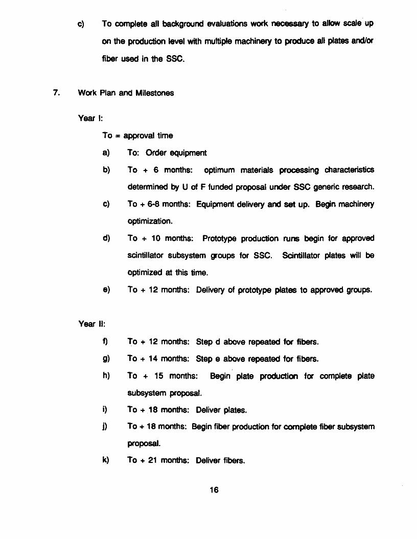
7. Work Plan and Milestones
Year I:
To = approval time
a To: Order equipment
b To + 6 months: optimum materials processing characteristics
determined by U of F funded proposal under SSC generic research.
c To + 6-8 months: Equipment delivery and set up. Begin machinery
optimization.
d To + 10 months: Prototype production runs begin for approved
scintillator subsystem groups for SSC. Sdntillator plates will be
optimized at this time.
e To + 12 months: Delivery of prototype plates to approved groups.
Year II:
f To + 12 months: Step d above repeated for fibers.
g To + 14 months: Step e above repeated for fibers.
h To + 15 months: Begin plate production for complete plate
subsystem proposal.
i To + 18 months: Deliver plates.
j To + 18 months: Begin fiber production for complete fiber subsystem
proposal.
k To + 21 months: Deliver fibers.
16
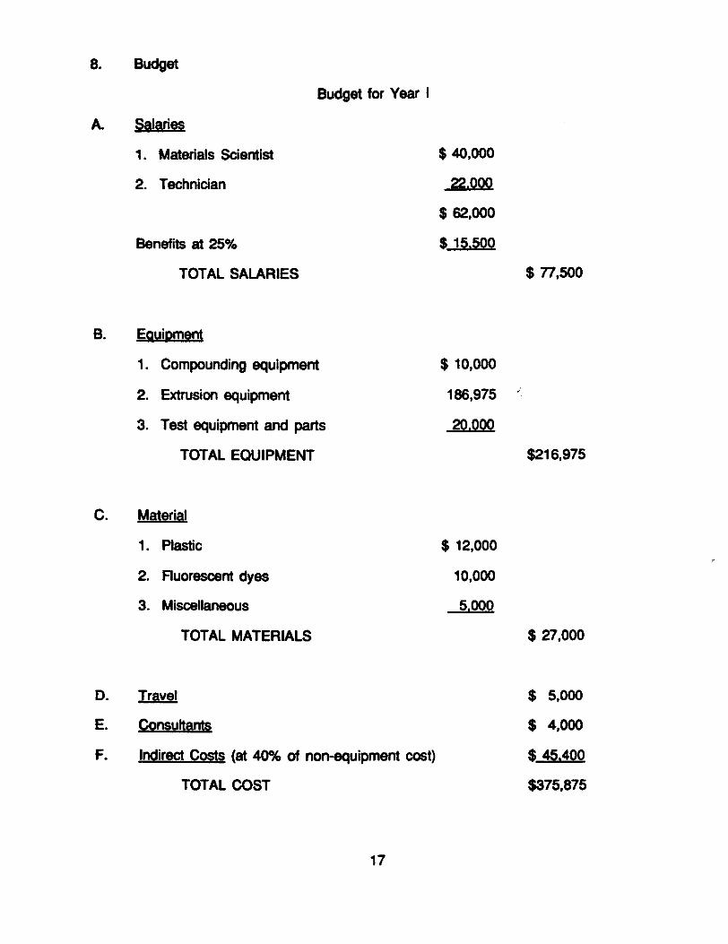
8. Budget
Budget for Year I
A. Salaries
1. Materials Scientist $ 40,000
2. Technician 22.000
$ 62,000
Benefits at 25% $ 15.500
TOTAL SALARIES $ 77,500
B. Equipment
1. Compounding equipment $ 10,000
2. Extrusion equipment 186,975
3. Test equipment and parts 20.000
TOTAL EQUIPMENT $216,975
C. Material
1. Plastic $ 12,000
2. Fluorescent dyes 10,000
3. Miscellaneous 5.000
TOTAL MATERIALS $ 27,000
D. j $ 5,000
E. Consultants $ 4,000
F. Indirect Costs at 40% of nonequipment cost $ 45.400
TOTAL COST $375,875
17
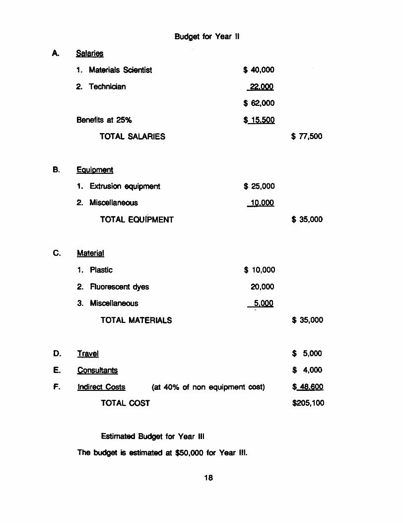
Budget for Year II
A. Salaries
1. Materials Scientist $ 40,000
2. Technidan 22.000
$ 62,000
Benefits at 25% $ 15.500
TOTAL SALARIES $77,500
B. Equipment
1. Extrusion equipment $ 25,000
2. Miscellaneous 10.000
TOTAL EQUIPMENT $ 35,000
C. Material
1. Plastic $ 10,000
2. Fluorescent dyes 20,000
3. Miscellaneous 5.000
TOTAL MATERIALS $ 35,000
D. flj $ 5,000
E. Consultants $ 4,000
F. Indirect Costs at 40% of non equipment cost $ 48.600
TOTAL COST $205,100
Estimated Budget for Year III
The budget is estimated at $50,000 for Year III.
18

9. Budget Justification
The equipment which Nanoptics proposes to purchase will result in the capability
to produce all types of scintillator and wavelength shifter needed for all of the
subsystem plastic scintillator calorimeters that have been proposed for the SSC.
The bulk of the equipment, the coextrusion equipment, is multifaceted. That is,
interchangeable parts allow for coextrusion of clad sheets or clad fibers. Two
equipment designers worked with us in the equipment design. Mr. W. Baker of Hills R
& D Inc., designed the coextrusion fiber spinning equipment. Hills A & D Inc. is a
company whose efforts are directed specifically toward the design of research level
fiber spinning equipment. They have developed an area of expertise in the spinning of
bicomponent fibers. Killion extruders designed the "coat hanger" film plate coextrusion
block for scintillator plate production. This plate design has been used by Killion in
prior successful attempts to produce encased films/plates.
APC designed a special ram feeder to convey the gel to the extruder.
This equipment contains a combination of features not available in any
commercially available systems. Therefore, the manufacturers will trial test the
equipment prior to shipping in order to make necessary adjustments in the processing
techniques.
The budget also allows for consultant fees. Three fiber specialists described
under the personnel section will assist us in equipment start up. A Materials Scientist
and Technician from Nanoptics will work on this project. Their salaries are included.
We have included in the budget the necessary materials allotment for polymer
and fluors.
The budget for Year II is mainly for salaries and materials. Equipment
allotments are for maintenance, spare parts, test equipment and possible coextrusion
dye configurational changes.
19

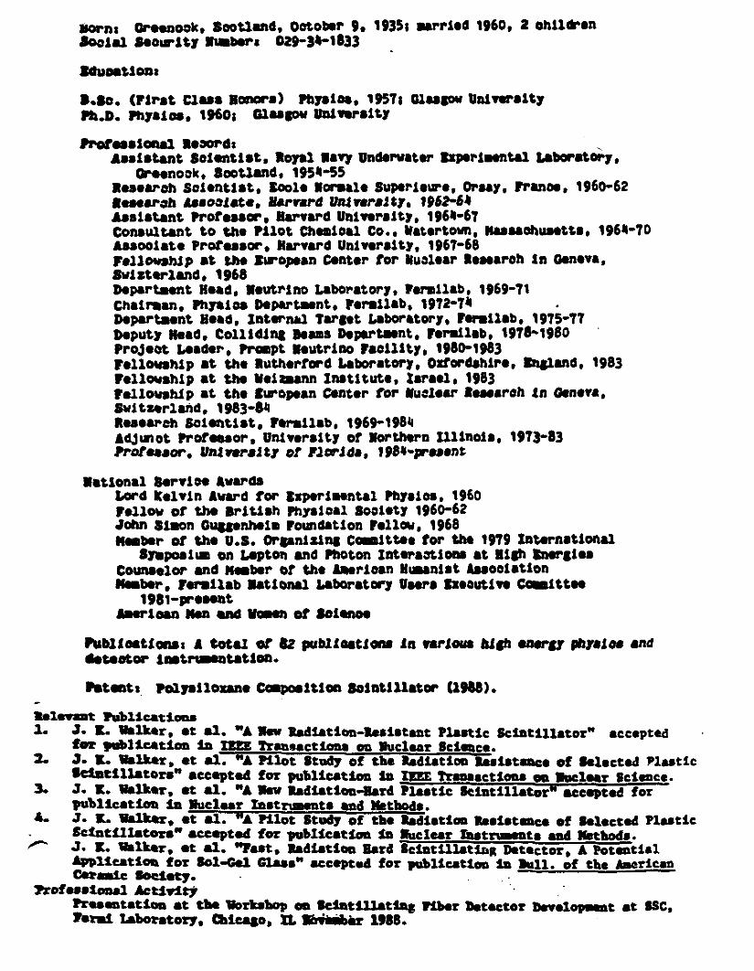
10. Personnel
Dr. J. K. Walker, President of Nanoptics has 30 years experience working with
scintillators. He was a consultant to Pilot Chemical Company, the largest producer of
scintillator in the US. He has had two SBIR’s funded for Nanoptics. He is also the
Head of High Energy Physics at the University of Florida.
Dr. J. Harmon, is an Associate Research Scientist in the Physics Department at
the University of Florida and Chief Materials Scientist at Nanoptics, Inc. She has
previously worked as a Research Scientists with Eastman Kodak Company. She has
extensive research experience in polymer processing and polymer synthesis. She
holds patents in the area of dye polymer interactions.
Dr. K. Wagener, Chief Chemist in Nanoptics, Inc., has eleven years of industrial
fiber spinning experience and is a leading polymer chemist now in the Department of
Chemistry at the University of Florida. Dr. Wagener’s group at the University of Florida
consists of 13 people and he is the project leader of a 2.5 million dollar DARPA project
on polymers. He also supervises a graduate student and a postdoctoral associate on
the synthesis of polysiloxane thermoplastic elastomers which is of direct relevance to
this project. This has recently been successful and a patent has been filed for this
process.
Dr. A. S. Abhiraman is a consultant to Nanoptics to the project on fiber spinning.
He is a Professor and Director of Polymer Programs in the School of Chemical
Engineering at Georgia Institute of Technology. Previous to that, he had several years
of industrial fiber spinning experience. He is internationally recognized as having made
pioneering contributions in fundamental aspects of fiber spinning. In 1987 he received
the Fiber Society Award for Distinguished Achievement.
20

Dr. W. Baker is the Technical Director in charge of designing fiber spinning
equipment at Hills Research and Development, Inc. of Melbourne, Florida. He has
extensive experience in the area of coextruding clad fibers. He is a consultant on this
project.
Dr. J. M. Kauffman is an expert in the area of fluor synthesis. He is a
consultant to Nanoptics, Inc., and has actively contributed to this project by designing
the molecular structures for primary and secondary fluors. He is an Associate
Professor at the Philadelphia College of Pharmacy and Science.
21
born: Greenook,Scotland, october9, 1935; sarri.d 1960, 2 ohil*’enSocial Seotrity iabsrs 029-3*-1833
IducatiOna
Lao. First ClasS Honors Physics,1957; Glasgow UniversityPh.D. physics, 1960; GlasgowUniversity
?rotessionalRecord:Assistant Scientist, loyal Navy UnderwaterRapefleentalLaboratory,
Ore.notk, Scotland, 195*-55Research Scientist, tool. portal. Superiewe, Orsay, Frano., 1960-62Research Msoflate, Harvard Unt varsity, 1962-64Assistant professor,Harvard Univsrsity, 196*-67consultant to the Pilot Chemical Co., Wat.rtown, wasuchusetts, 196*70Associat. Professor.Harvard University, 1967-68Fellowship at the tiropeanC.nt.r for Nuclear Research in Geneva,Swizterland, 1968DepartaentHead, Neutrino Laboratory, Fermilab, 1969-71Chairman, PhySics Department. Fermilab, 1972-7*DepartmentBead, Internal Target Laboratory, Fermilab, 1975-77Deputy Head, Colliding learns Department,Fermilab, 19781980Project Leader, Prapt Neutrino Facility, 1980-1983Fellowship at the Rutherford Laboratory, Ozfordshire, Ingland, 1983Fellowship at the Weiann Institute, Israel, 1983fellowship at the twopeanCenter for Nuclear Researchin Geneva1Switzerland, 1983-SMResearchScientist, Fermilab. 1969-198kAdjimot Professor,University of Northern illinois, 1973-83Professor, Vial varsity at Florida, 19$’J-rn.nt
National ServiDe $wardsLord Kelvin Award for ExperimentalPhysics, 1960Fellow of the British Physical Society 1960-62John Simon GuggenheimFowadationFellOw, 1968Saber of the u.s. OrganizingCtttee for the 1979 International
Syspositaon Leptob and Photon Interaction at High SnergiesCounselor and saber of the American Haanist AssociationSaber, ynilab National LaboratoryUsers SzeoutiveCceittee
1981-presentAmen can Sen end vonet of Science
Publications: A total of *2 publications in venous high energy physics anddetector instrtasntstioa.
Pstent: PolysilozaneCapo.itioc Scintillator 19*8.
televeat Publications.1. .7. t. WalMr, et *1. "A Jew Radiation-ResistantPlastic Scintillator" accepted
let publication in pxr. Transactionson Nuclear Science.2. .7. 1.. Walker, et *1. "A Pilot Study of the Radiationbaistanceof SelectedPlastic
Idatillators" acceptedfor publication in lEn Transactionson Nuclear Scirce.3. .7. t. Walker, at *1. "A isv Radiation-HardPlastic Scintillator" accepted for
publication in Nuclear Instrumentsand Methods.4. .7. t. Walker, Si a].. "A Pilot Study of the Radiation Resistanceof SelectedPlastic
Scintillaton" acceptedfor publication in Nucicar Tnstn.-ts and Methods.r .7. K. WaIter, et a].. "Fast, Radiation Hard Scintillating Detector, £ Potential
Application for Sd-Gel Glass" acceptedfor publication in lull. of the AsoricanCeraic Society.
rofessiona1Presentationat theWorkshop on Sciat4listing Fiber Detector Develocmt..tat SSC,Fermi Laboratory, fticago, IL Ler 19*8.
CURRICULUM vvr*JUUE P. HARMON
PERSONAL SirthdatMarch 28, 1949
Education 8.5. ChemIstry,MercyhurstCollege, Erie, P& Cum I.aude
Chemistry,DuquesneUriversity, Pittsburgh,PA
MaterialsScience,Univ.of Rochester,Rochester.NY1983
Specialization Solid statepropertiesof polymers - mechanicalproperties,transportopeniesandstructure-propertyrelations.Photochemistry- Polymer,dye light stability.
Employment 1988-Present,NanopticsInc., ProgressCorder,MachutFlorida, 32615. Chief Materials Scientist,studyingmechanicalpropertiesof polymers,polymer processing,anddye polymerinteractions.
1989-Present,Dept. of Physics,Univ. of FL, Gainesville,Florida, AssociateResearchScientist. Hiph EnergyPhysics,ResearchingMechanicalPropertiesof polymers,polymerprocessing,and dye polymerInteractions.
1983-88,EastmanKodak ResearchLaboratories,Rochester,NY. ResearchScientist. Researchactivities includedmechanicalpropertiesof polymers-impactmodifications;dye dffusion, solubility and Immobilization Inpolymers; polymerprocessingof composites. extrusion,compounding,filler dispersion.
197677UCO Optics, Scottsville, NY, PolymerResearchChemist Researchactivities Included biomedicalpolymers; diffusion induceddeformationand swelling inhydrophilic polymers; polymer synthesis;the effect ofstructureon swelling andtearstrength.
1973-75,PPGIndustries,Pittsburgh,PA, TechnicalServiceRepresentative.Technicalactivities includedpolymercompoeltes;mechanicalpropertiesof composites;polymerprocessing- coating, laminatingrotational molding.
TEACMNG
‘MechanicalPropertiesof Polymers,’graduatelevelcourse.University of Rochester,Rochester,New York.
23

"PolymerChemlstiy,’ St. JohnFischerCollege, Rochester,
PUBLICATIONS AND PATENTS
1. transportof Alcohols In Deformed PMMA," J. P. Harmon and I. C.M. LI, Annuals New York Acaderiv of ScienceConferenceon‘Structureand Mobility In Molecular and Atomic Glasses,’371,310, 1979.
2. ‘Methanol TransportIn PMMA: The Effect of MechanicalDeformation,’J. P. Harmon,S. Lee and J. C. M. U, J. Polvm.Sd: Part A: Polym. Chem..Vol. 25, 3215-32291987.
3. ‘Anisotropic MethanolTransport in PMMA After MechanicalDeformation,’J. Harmon,S. Lee and J. C. M. U, Polymer. Vol.29. 1221-12261988.
4. ‘Internal Stressesand PhysicalAging,’ J. P. Harmon andC. LBea.Eneethoerts HandbookVol. t EngIneering
5. ‘Colored ElectroscopicTonersContainingQuenchedEsterifledRhodamineDyes,’ Vt T. Gruenbaum,J. P. HarmonandI.. C. Roberts,EastmanKodak Company, Rochester,NY, U. S. PatentNo.
u.832.
6. ‘Toners and Yellow Dye CompoundsUsedTherein,’ D. D. ChapmanandJ. P. Harmon, EastmanKodak Company,Rochester,NY, U. S.PatentNo. 4,734,349.
7. Two patentspendingEastmanKodak.
PRESENTATIONS
1. SyracuseUniversity, Syracuse,New York 1982, ‘PenetrantTransportIn DeformedPolymers,’J. Harmon,New York AcademyofSciences,New York, New York 1980.
2. ‘Enthalpy Recoveryin Polystyrene,’J. Harmon, New York Academyof Science,New York, New York 1980.
3. ‘Alcohol TransportIn DeformedPMMA,’ J. Harmon, FloridaAdvancedMAterials Society,Palm Coast,FlorIda 1987.
4. ‘Microhardnessof Polymer Composites,’J. Harmon, R. Crawfordand CL. Beatty, Florida AdvancedMaterialsSociety, Palm Coast,FlorIda 1987.
5. ‘DiffusIon In Deformed Polymer Matrices,’ J. Harmon,AmericanChemicalSociety,Orlando,
24

8. ‘Study of Anti-CorrosionCoatingsfor StainlessSteel,’J.HarmonandCi.. Beatty, SoutheasternSection,AmerIcanChemicalSociety,Orlando, FlorIda 1987.
7. ‘The Effect ci SorbedHydrocarbonson PolymericFoamPRoperties’J. Harmon,,W. Wdllams, J. Dixon andC. L. Beatty,.American óhemlcalSociety,Orlando,florida 1987..
8. ‘Use of DeformationIn Different Statesof Stressto Bias theGlassTransitionTemneratureand RelaxationBehavior,’ Y. Katz,J. Harmon andC. L. Latty, The Societyof Rheology,Atlanta,Georgia1987.
9. ‘LIquid TransportIn AnelasticaltyDeformedGlassyPolymer,’ J.P. Harmon,S. Lee and J.C.M. Li, PolymerProcessingSociety,Fourth Annual Meeting, Orlando, florida 1988
10. ‘Fatigue ResistantAnti-Corrosion Coatings,’J. Harmon, S.Singleton,andC. L Beatty, Polymer ProcessingSociety,FourthAnnual Meeting, Orlando,Florida 1988
11. ‘Dynamic MechanicalPropertiesof PVC Plastisols: The Effects ofCure Conditions and PlasticizerMigration,’ W. Daher, C.Garrett, J. Harmon,and C. L. Beatty, Polymer ProcessingSociety,Fourth Annual Meeting, Orlando, Florida 1988
12. ‘Sorption of Liquids frito Foamsand SubsequentChangesInMechanicalPropertiesof the Foams,’J. Harmon,D. Wingard, D.Bennett,J. Dixon, W. Williams, and C. 1. Deafly, PolymerProcescingSociety,Fourth Annual Meeting, Orlando, Florida
ia ‘Nuclear MaanetlcResonanceImaging of Flow During PolymerExtrusion,’ tH. Marecl, J. Harmon,and C. L. Beatty, PolymerProcessingSociety,Fourth Annual Meeting, Orlando,Florida
25
Associate Prgf gf AIu!t INS to dotq aidQt.a... Canter far Macronplecuarence and Ercineerkia. Inr hr of FIarldo. Gainesville. Teaching, research, aid administrationrelated to organic aid polymer chemistry - current research group of 12 people postdoctoral asia-elates, graduates aid undergraduates aigag.d In research related to saw synthetic methods to createwell phase separated multiphase polymers, conductive polymers, aid donor acceptor polymers.
Dw-’tnnt ltd. AICZO nv. Anierlcai tithe Res.,urch. AflvNIe. NC 1973 to Auaust%4. birected activities of IS people engaged In buRt polymerIzatIons aid structure4iroperty deter.
nunatlons e research In merrèraies, Then, blopolyniers, polymerizatIon catalysis, conductive poly.tiara, end polymer d1...nçosltlai.Promoted four times &tkig this eleven year period eaearch Department Iliad 1983.54; MentiraieResearch Section Head l98243; Research Scientist, Polymers IflJ3jSenlor Research Diemlit 1975.
- offered positIon as Technical Director of Membraia, kit. an AICZO in venture in CalifornIa In1983,0 poeltlai I declined In order to enter =4uics.From $975 ortll 1984 I did collthaatlve research with professors at MIT, Techniuche IMiversltotTw,nte Netherleids, Clemson, Virginia Tech aid Georgia tech.
Mwrct Professor at OsSstn1 tMlverslty of Itrth Carolina t Aflvllle l75 sq ftuaut I84.tvenlng teachIng of organic aid polymer courses two courses each year a Ira of the chemistrydepartment’s students awarded Fubrlght Scholord4s during my lawn there.
" tvok,tlan .1 Structure aid Prw,artles in e FberFormation frame Thermoplastic Polyester.PolyettierSegments Copolymer’
P oIyester Polyether Segmented CapoIn... Stobiflied Against Degradation by Ultraviolet Llht viaCopotymerlzatlon wIth Analogs of 2,2,4-titrana-thylperIdkie Derlvatlvet
P ,l.4lOtOlfl Pelyoinlds Pol,,..,ethyIene Sled, Cop.,fii.,C
ft A. .klwtsori aid it. B. W.r..u. U.S. P "Segnwitid Thermoplastic Capobas..Potent 4,2Q,I14 lISt -
PROFSflØL COCMTCNForty rational aid Inturnatlanot presentations, nineteen obstracted piblicatlans since lolning facultyAugust 1984 - forty-five ps.tllcathns/patents total - g top SO l.Mlverslty .f Florida r.,4arsrec.gr,Ized by President Marthall tiler, 958 - a Chemistry teacher of the Year, IS a college ofLterol hit. & Sciences Tatier of the Year Fkdlet, IN?.Ptlaay force In sstthII*big Chemistry Deportment Industrial Affiliate, Prenn, SM? . eetoblS,edthe Polymer Chemistry Curriculum Development Award a PttIenal sword wIth Polymer Division ofAmerican Chemical SocIety, INS - wWier of Lit. PresIdent’s Award, 1950. enly desIst aid yaat person ever to receive Enko kicaitive Sloth Award I ISO Sn.. ‘.J, P79.
tS. OiemlstrytMoth Mba, Clemson LiniveSty, IØ- Ph.D. Gpath end Polymer Ovemistry, MI.
varsity of Florida, $973 - neried, two en a Margaret, Pan-mn. Faculty, Deportment ef Englidi,Suit. Fe Coewvaailty College, teaching literature end oonoeItIan - David, op. IS, 10th grade Dishhob High School - Peter, age 12,7th grade Fart Clam. Middle Sdiaol - two brothers, one e Ph.D.chemist, the other e ‘sInIster -father e retked hit edieel h.4i....
ISETh S WAW&RC.MRICLL VITA
A. S. Abhlranni aid K. B. WagonerJOI.RNAL OF POLYMER SOtPOLYMERPHYSICS £0111 0% , OS1%?.ftkJJi..s...,KtWan.. endR.C.Lilly, U.S. Potent 4,3224221982.
K.. B. W...,ar, B. W. Spivey, Jr. aid.LOiapmai, Cons Potent
P. R. Cieung, C. W. Roberts aid IC. B.APPt. POLYM. 5049,
O0 ‘Synthesis, PtiotodegradatIain and trait traisfer Ine Series of Polyethylene Teruihttcietea4,.Ne*iolredlg.it...ilot. Ccpolynart

BIOGRAPHICAL SKETCH OF Dr. A. S. ABHIRAMAN
ProfessorSchoolof Chemical EngineeringGeorgiaInstituteof’ Technology
Atlanta,GA 30332
EDUCATIONAL BACKGROUND
PS!!!Ph.I. 1975 NC. State UniversityM.S.. 1972 N.C. StateUnivealtyB.Tach. 1969 UniversItyof Madras
EMPLOYMENT HISTORY
This maProfessor GeorgiaTech 1986-AssociateProfessor Georgia Tech 1981-85AssistantProfessor Georgia Tech 1979-80RheologyGroupLeader American EnkaResearch 1977-79& InternalConsultant CenterSeniorResearchEngr. AmericanEnkaResearch 1974.76& Internal Consultant CenterBasic ResearchAssistant N.C. StateUniversIty 1969-74ResearchFellow Textile ResearchInst. Sumsr ‘72
CURRENT FIELDS OF INTEREST
1. HIgh PerformanceFibers,especiallyCarbon/Graphite and CeramicFibers.
2. ThermodynamIcsandKInetics of CrystallisatlonIn Polymers.
3. PrincIples of Fiber FormationRheology PhaseTansitions.
4. Porous Polymer Structures.
5. Polymer Morphology.6. StccbastIcAspectsIn PolymerScienceRelaxation,Pclymerlsstlon.
PROFESSIONAL ACTIVITIES
Member,The Fiber Society,1981 to present.
Member,ACS, 1978 to present.StudentMember,Phi Kappa Phi.Student Member,Chemistry Honorary SocletySessionChairman,GordonResearchConferenceon Fiber ScIence,1984 and 1986.
27

AWARDS
- The FiberSocIety Award for DistinguishedAch1evment198fl.- The fWlowbg awards havebeen earnedby tradatestudentsIn Dr. Abhlraman’s
gro11p
1. SIgma Xl Awards for OutstandIngThesisResearchat Georgia Tech3awardsIn the lut 4 years.
2. FIber SocietyStudent PaperAward 1987.3. SPE-SoutbernSection-StudentPaper Award 1987.
CONSULTING
1. AmerIcan EnkaCompanyFiberFormation.2. Enon Enterprises PItch-basedCarbonFibers.3. Owens-CorningFiberglassHigh PerformanceFibers.4. tJzdon Carbide CarbonFibers.5. Coatsand Clark SyntheticSewingThread.6. RIaone-Poulenc,fltnce FiberFormation
28

Biographical Sketch
Name: Joel N. kauffman
£ducatiowPhiladelphia College of Pharmacy& Science, 8.5., Chemistry, 1958Massachusetts Institute of Technology, Ph.D. ,Organic Chemistry, 1963
Honors:Merck Chemistry AwardGriffes Scholarships 3 for highest GPA at P05American Institute of Chemists MedalAmerican Chemical Society AwardPOS Alumni MedalNational Science Foundation Regular Fellowships 4
Experience.Philadelphia College of Pharmacy & Science - 1979 to present
Associate Professor of Chemistry - 1985 to presentAssistant Professor of Chemistry- i9791985Taught General, Organic, and Medicinal Chemistr$ research onmedicinsls and fluorescent and/or laser dyes
Massachusetts College of Pharmacy, Boston, MA - 1977-1979Research AssociatE synthesized potential anticancer drugs
New England Nuclear Corp., Pilot Chemicals Div., Watertown, NAResearch & Development Director - 1972-1976Senior Development Chemist - 1969-1972Synthesized oligophanylenes as fest-response fluors for plasticscintillators. improved production methods for fluora such asP90, POPOP, Bit-Nsa, DPS, TPSD. Formulated the liquidséintillator products Aquasol-Z, Oxifluor-H2O, Oxlfluor-C02,Biofluor, Riafluor, Econofluor, Aqusfluor, and Brays Solution.initiated commercial devslooment of laser dyes.
l.C.l./Organics/lnc., Dighton, MA- 1967-1969Research Chemist; developed syntheses end processes forplastics additives for PVC and PP.
Massachusetts College of Pharmacy, Boston, NA - 1964-1967Post-Doctoral Follow; synthesized potential antiradiatlon andantimalaria drugs under contract to the Ii. S. Army MedicalCorps.
Thiokol Chemical Co., Reaction Motors Div., Defwille, NJ- 1963-1964Research Chemist; synthesized flitrosocarborane monomers fornitroso rubber for low-temperature use under DOD contract.
Pislicationi last fIve years
A. N. Fletcher; D. C. Bliss, J. N. Kauffman, ‘Lasing and FluorescentCharacteristics of Nine New Flashlamp-Pumpable Coumerin Dyes in Ethanolend Ethsnol:Water, Optics Commune. fZ 57 1983.
CahaesdV D LaserTschaole, Iv SvMSls eel Evatusties VMini RS-1S1fta Least Da.Ml N. Led! Se,Ca Dept, PWIa. Cal. PWfl Scisas
w. 0. Foye, V. H. Kim, .1. N. Kauffman, ‘Synthesis and AntileutemicActivity of 2-2-Piethylthio-2-aminovlnyl -I-methylquinolinium iodides’,J. Pharm. Sd. 22.. 1356 1983.
Lena A. Dslisser-Matthews and Joel N. Kauffman, 3-Arylcoumarinsas Fluorescent indicatOrs’, Analyst .LQj, 1009-111984.
Joel II. Kauffman and Joyce D. Zogott, ‘Drawing Chemical Structureswith the Apple Macintosh’, The Journal of Computers in Mathematics andSclSnce Teaching’, Fall, 198$, 32.
Joel N. Kauffman, Charles J. Kelley, and Richard N. Steppel,‘o,o-Bridg.d Oligophenylene Laser Dyes, and Dyestuff Lasers and Methodsof Lasing Therewith’, U. S. 4op/. f//sd /8 Feb fl.
Joel N. Kauffman, ‘A Simpe Method for the Determination of theOxidation States of Atoms’, J. Chem. Ed. 1, 474 1986.
Joel N. Kauffman, ‘Chemistry Calculations Using a CommercialSpreadsheet Program on a Microcomputer’, The Journal of Computers inMathematics and Science Teaching’, Spring, 1987, 38.
Joel N. Kauffman, C. J. Kelley, A. Ghiorghis, C. Neister, P. Prause,L. Armstrong, ‘Bridged Quaterphenyls as Flashlamp-Pumpable LaserDyes’, Laser Chemistry j, 343 1987.
J N. Kauffman, C, J. Kelley, A. Ghiorghis, ‘Potential HighPulse-Energy Laser Dyes Related to 4PyMPO-MePTs’ Proceedings: DyeLaser/Laser Dye Technical Exchange Meeting, University of New Orleans,LA, 20 Apr 87, U. S. Army Missile Command Special Report RD-0C-87-l,25.
- C. J. Kelley, A. Ghiorghis, J M. Kauffman, ‘Ultraviolet Laser Dyesinvade the Visible’, Proceedings: Dye Laser/Laser Dye Technical ExchangeNeeting, University of New Orleans, LA, 20 Apr 87, U. S. Army MissileCommand Special Report RD-Dt-87-I, 55,
Joel P1. Kauffman and James H. Bentley, ‘Effect of Various Anions andZwitterions on the Lasing Properties of a Photostable Cationic Laser Dye’,Laser Chemistry, /nprns.
Joel N. Kauffman, C. J. Kelley, A. Ghiorghis, E. Nelater, L.Armstrong, ‘Cyclic Ether Auxofluors on Oligophenylene Laser Dyes’, LaserQeem., loran.
J. N. Kauffman, C. J. Kalley, A. Ghiorghis, C. Neister, P. Prause, L.Armstrong, ‘Ultraviolet-Emitting Flashlamp-Pumpable Laser Dyes Derivedfrom Bridged Quaterphenyla’, Proc. intl. Conf. LANDS 77, Society forOptical and Quantum Electronics, Late Tahoe, NV, ii Dec 87, morn,,
IMsasead V Dp LaserTechnalegv fl SgMSais aS tvsluatlea ef Mini RsI4StUse Laser Due,It Kadita, Chat Cast. PWla. Cal. Pkv. & tisase
BIBLIOGRAPHY
1. RN. Stepped Private Communication
2. T.G. Pavlopoulos et at., J. A. Chem. Soc. , 6568 1974.
3. M.K. Bowen, Study of New Polysiloxane-based Scintillators, M.S. Thesis, University ofFlorIda, 1988.
4. M.K. Bowen, et at., IEEE. NucI-.Sci. Symp., 1988, pre-publication manuscript.
5. GE Silicones, ‘High Performance Elastomers" Technical Information. 1987. GECompany,Watertord,NY 12188.
6. H.A. PohI, Textile ResearchJournal, June 1958, p. 473.
7. S.Y. Fok et al., Textile Research Journal, Feb. 1966, p. 131.
8. PatentJapanese Simito Elec. Ind. JP 63121004.
9. G. Keiser, Cotical Fiber Communication, McGraw Hill, 1983, p.18.
31
too
75
0zoo
Undoped PolyvinyltolueneZrreltatsd in Argon
2SLaC
50aECC
4- 25
Undoped Elastomeric PolydimethyldiphenylsioxaneIrradiated in Argon
I
aooWavelength nm
300 a BOO BOO 700
100
WADlam MI
FIGURE I

013
011003954
Structures of Oligophenylene Dyes
FIGURE II
DiImthyIqUaIUptICUyI 1 01100 374 A 2
‘0013
C1I00 386 3
Pr . Prft
33
Relative Light Output. %120
100
____
BO -___
60 -_______________
40
20
I
0 . 3
Dose,Mrad
SeriesA I SeriesB
TnadlMlos dSeI asSaspln dOUGO 374*4. ad 011CC iT $ SPOy41onae S-
FIGURE III34

- as Pa
Irradiation in Argon. 1,2,3-0,3,10MrS respectively
FIGURE IV
j3UI
ass ass
I.I
RELATIVE LIGHT OUTPUT
LIGHT OUTPUT, %
Irradiation In Argon
0 5 10 15 20 25
DOSE, MradLI. 450- Nanoptics, Inc. scintiflator emitting at 450 n.m.; tScwn3
3B.C. 408- Bicron Corp. scintillator emitting at 408 n.m.
Fig. V
120
1
0
3’
ABSORPTION OF THE SECONDARY DYE
AT THE EMISSION WAVELENGTH
500 550 600 650 700nilWAVELENGTh
750
10
9
B
7
60-4
5Sz
5
4
3
2
0400 450 Boo
FIGURE VI

APPENDIX I
38

4tNANOPTICSnwoRvoRAmDUNIVERSITY OF FLORIDA
Research& Technolo&’ ParkOnePitgr Boulevaa4Ba 37
M.dnn, florida. 32613Pho,ic 904-462-2094
Far 904-462-3932
Nanoptics, Inc., is a Florida corporation created in 1987 for the purpose of
commercialization of advanced nuclear radiation detector technology developed at the
University of Florida This work at the University is supported by the Department of Energy
at over $300,000 per year. The technology has application in a broad range of advanced
nuclear detectors used in the five billion dollar Superconducting Super Collider to be built in
Texas, and other atom smashers around the world. There Is also a growing need for
these detectors in other applications such as health physics, waste monitoring, nuclear
safeguards, environmental protection and process control. The three principal unique
attributes of the plastic scintillator technology of Nanoptics, Inc., are:
1. the extreme resistance to degradation of the plastic from massive amounts of
radiation. In this regard, the product is about one hundred times better than
previous material.
2. the plastic can be formulated to be flexible and easily formed to any shape
thereby eliminating expensive machining costs.
3. extreme resistance to environmental hazards such as vapors of aromatic
compounds, acids or mechanical stress.
The technology is protected worldwide by a patent. The U.S. government has given
ownership of the patent, know how, and practice thereof to the University of Florida under
a provision of U.S. law. The University of Florida has negotiated an exclusive worldwide
license with Nanoptics, Inc., to practice the patent associated with this technology. In
return, for the exclusive licensing rights, Nanoptics, Inc., has provided the University of
Florida with a licensing fee, partial payment of patent fees and maintenance fees, part
ownership in Nanoptics, Inc., and a royalty payment on all net sales.
39
Nanoptics. Inc., Is financed by pdvate funds of the founders and by the receipt of
two Small Business Innovation Research grants received from the National Science
Foundation and the Department of Energy. In addition, negotiations are proceeding to
receive venture capital funds. Nanoptics, Inc., is located at the Progress Center, One
Progress Boulevard, Alachua, Florida in the heart of the rapidly expanding University of
Florida Research and Technology Park. The same building houses the University’s
Advanced Materials Research Center AMRC laboratory, thereby assuring ready access to
AMRC equipment and staff. The Material Science Department has an inventory of
$5,000,000 of advanced materials analysis and characterization equipment and a fully
trained technical staff.
Nanoptics, Inc., has a management, technical staff, and consultants with many years
of experience in high technology materials development, polymer chemistry and fluorescent
compounds. Dr. James K. Walker serves as the corporation’s President and Principal
Scientist. Dr. Ken Wagener serves as Chief Chemist and Dr. Julie Harmon as Chief
Materials Scientist. The corporation has a consulting committee of distinguished scientists
from Industry and several Universities. A Board of Directors is being formed at this time.
The composition of this Board will include representation from the sources of venture
capital.
40

APPENDIX II
41
1EIIIRIDflU. Escab S D.nI.pa.aIFib., Exfruaia pdna
7785 EWs Rd.WestMelbournePIOTId*, USA 32904Phone: 407 724-2370Vex: 407678-7635Telex: 469353
September 13, 1989
ors. Suite Harmon & Jamie Walkeruniversity of FloridaDepartment of Physics210 Wifliasson HallGainesville, Vt. 32611
Subject: mi-component Monof iiQuote lSllA
Dear Dri. Harmon & Walker:
We enjoyed your recent visit and were impressed by your novel approach to the production of optical fibers.
We have given considerable thought to the design of your bi-component spinning machine.
Appended you will find a detailed Equipment Description for theequipment that we envision. Please be aware that this design is inan evolutionary stage and could change as more of these concepts yothrough the design process. However, we are cumfortable with thisas a good first step on. which we can base a reasonable cost estimate. Please read the Equipment Description carefully to ensurethat we have properly understood your needs.
PRICE
our price for a machine exactly as described in ED lSllAis $l59,flO.This price is POD Melbourne and is good for 90 days.
We recommend the purchase of some spare parts with this machine. inyour case, you are fairly accessible to HRD and we can support yourather easily, with commonly available parts. we suggest that. youpurchase only spare parts having long delivery or inexpensive sothat you will be able to minimize downtime to have thea on hand forimmediate replacement. we have not developed a specific list ofthese parts but past experience suggests that 5% of the machinepurchase price would be a reasonable allowance.
42

Ers. Harmon & Walker Page 2University of Florida september 13, 1989
SCHEDULE OF PAYMENTS
15% with Purchase Order25% midpoint between p.o. and shipment35% two months before shipment25% at shipment Net 30 days after the customer has veri
fied acceptable mechanical and electrical operation ofthe machine.
DELIVERY
Normal delivery for this kind of equipment is six to eightmonths. However, this is very dependent upon the workloadwithin ERD. Delivery dates should be confirmed at thetime of order placement.
We hope that you find this information clear and acceptable. if youhave any questions, please do not hesitate to call me.
We look forward to working with you on this very interesting andexciting project.
Yours fai
William P. Raker
Enclosure
43

EQUIPMZNT DESCRIPTION
Research Hi-Component Monofilament spinning Machine
ED l5llA
September 1989
GENERAL
This document describes a synthetic fiber spinning machine designedto carry out research into large diameter bi-component monofila-tents.
this machine uses two one-inch diameter extruders and will produceone strand of water quenched monofilament bi-coiponent material.Because of the research nature of this product, we can not say whatthe basic throughput limitation will be. However, each extruderwill be capable of 12 pounds per hour based on polypropylene.Extrusion temperatures are controllable over the range ambient up to300 degrees C. The water quench bath is capable of handling atleast two filaments and the take-up, one filament at speeds up to150 meters per minute. this speed is equivalent to 15.5 pounds perhour for a lam diameter filament of density of 1 gm/cc. While thewinder and spin pack is designed for one single strand, this couldeasily be expanded to at least two by future changes or additions tothe spin packs, guides, and winders at nominal cost.
DETAIL
This machine will consist of;
One conventional chip hopper 0.7 vu. ft. with window, slide gatevalve, and nitrogen injection nozzle.
The hopper for the second extruder will require a crammer feederarrangement. While this is not yet defined, $1,900 direct cost toERD is allowed in the estimate.
EXTRUDERS, Qty. 2 - 1 24,1 with 3 Hp wertec brushless DC motors,three heat zones but no cooling blowers. Screw design will befinalized later to be appropriate for the high viscosity liquid andflouropolymer feeds.
PUMP HEADS, Qty. 2 - this unit is mounted directly on the extruder. It carries a meter pump on its upper surface and connects themetered teed materials to a transfer line to the spin heads.
44.
EQU IPNT DESCRIPTIONResearch fl-Component Monofilament Spinning Machine
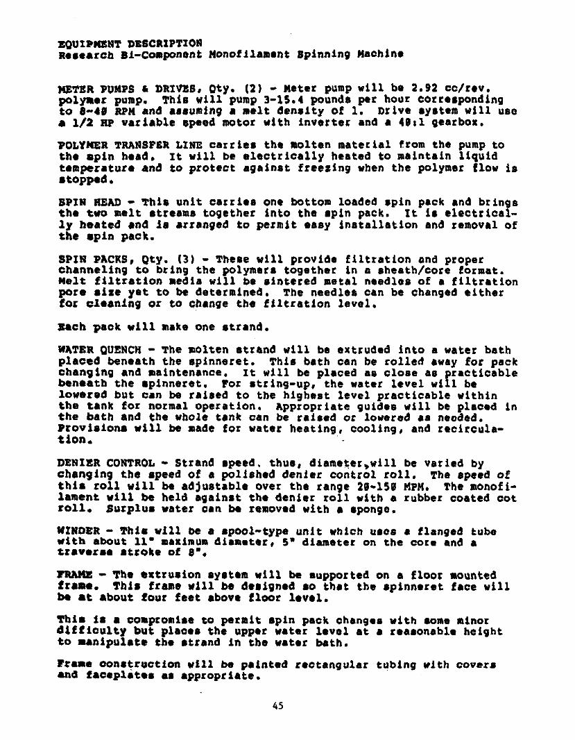
4E?IR PUMPS & DRIVES, Qty. 2 - Meter pump will be 2.92 cc/rev.polymer pump. This will pump 3-15.4 pounds per hour correspondingto 8-40 RPM and assuming a melt density of 1. Drive system will usea 1/2 up variable speed motor with inverter and a 40*1 gearbox.
POLYMER TRANSFER LINE carries the molten material from the pump tothe spin head. It will be electrically heated to maintain liquidtemperature and to protect against freezing when the polymer flow isstopped.
SPIN HEAD - ‘this unit carries one bottom loaded spin pack and bringsthe two melt streams together into the spin pack. It is electrically heated and is arranged to permit easy installation and removal ofthe spin pack.
SPIN PACKS, Qty. 3 - These will provide filtration and properchanneling to bring the polymers together in a sheath/core format.Melt filtration media will be sintered metal needles of a filtrationpore size yet to be determined, the needles can be changed eitherfor cleaning or to change the filtration level,
Each pack will make one strand.
WATER QUENCH - ‘the molten strand will be extruded into a water bathplaced beneath the spinneret. this bath can be rolled away for packchanging and maintenance, It will be placed as close as practicablebeneath the spinneret. For string-up, the water level will belowered but can be raised to the highest level practicable withinthe tank for normal operation. Appropriate guides will be placed inthe bath and the whole tank can be raised or lowered as needed.Provisions will be made for water heating, cooling, and recircula-tion. . -
DENIER CONTROL - strand speed. thus, diameter,will be varied bychanging the speed of a polished denier control toll. The speed ofthis roll will be adjustable over the range 20-150 MPH. The monof i-lament will be held against the denier roll with a rubber coated cotroll. Surplus water can be removed with a sponge.
WINDER - This will be a spool-type unit which tacos a flanged tubewith about 11’ maximum diameter, 5’ diameter on the core and atraverse stroke of 0’.
FRAME - The extrusion system will be supported on a floor mountedframe. This frame will be designed so that the spinneret face willbe at about four feet above floor level.
This is a compromise to permit spin pack changes with some minordifficulty but places the upper water level at a reasonable heightto manipulate the strand in the water bath.
Frame construction will be painted rectangular tubing with covetsand faceplates as appropriate.
45
EQUIPMENT DESCRIPTIONResearch Ri-Component Monofilament Spinning Machine
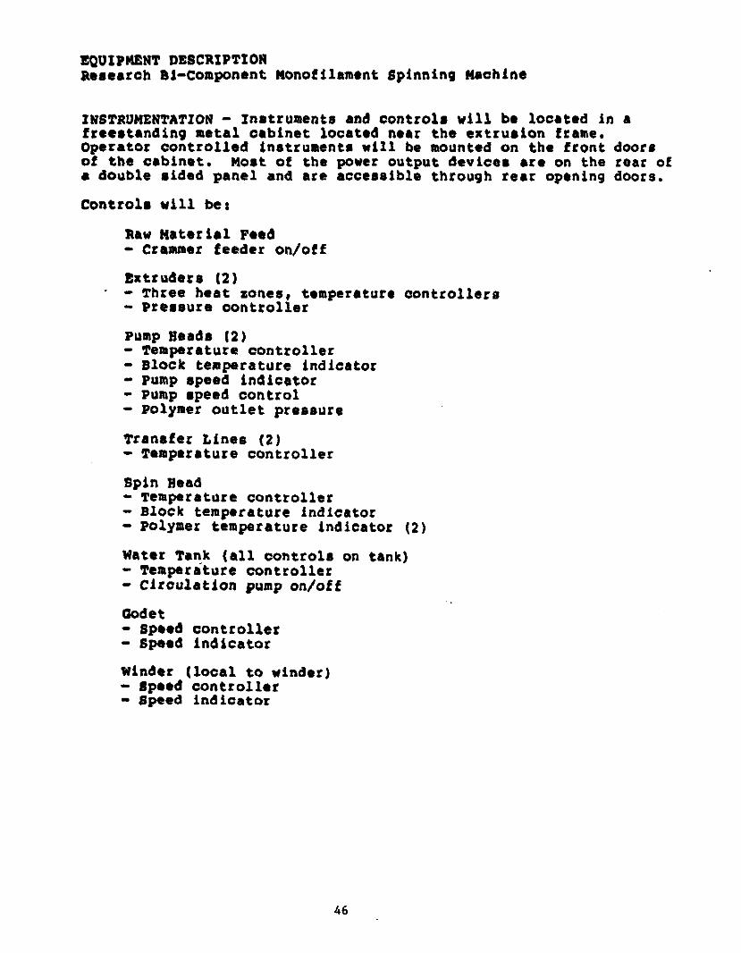
INSTRUMENTATION - Instruments and controls will be located in afreestanding metal cabinet located near the extrusion frame.Operator controlled instruments will be mounted on the front doorsof the cabinet. Most of the power output devices are on the roar ofa double sided panel and are accessible through rear opening doors.
Controls will be:
Raw Material Feed- Crammer feeder on/off
Extruders 2-
- three heat zones, temperature controllers- Pressure controller
Pump Beads 2- Temperature controller- Block temperature indicator- Pump speed indicator- Pump speed control- Polymer outlet pressure
Transfer Lines 2- Temperature controller
Spin Bead- Temperature controller- Block temperature indicator- polymer temperature indicator 2
Water Tank all controls on tank- Temperature controller- Circulation pump on/ott
Godet- Speed controller- Speed indicator
Winder local to winder- Speed controller- Speed indicator
46

EQU IPMENT DESCRIPTIONResearch 31-Component Monofilament spanning Machine
CONTROLS
GENERAL
- Temperature controllers will be Barber Colman 580AT or equivalent,
- Heat zones are powered by solid state relays.- pressure controllers, indicators, and transducers will be
Dynisco or equivalent.- All rotating systems are equipped with illuminated start
pushbuttons of industrial grade oil tight cortctruction.- Wires will be individually labeled with wraparound labels and
connection terminals will be numbered using the HRD numberingsystem.
- Instruments will be calibrated in degreec centigrade, metersper minute, pounds per square inch and inches water gauge,unless specifically requested otherwise.
- The choice of other instrument types is acceptable at thecustomer’s option. Some adjustment in price may be necessaryfor this.
MISCELLANEOUS
Includes a roll removal fixture for ERD manufactured roll.
Includes spin pack installation tool.
This system will operate properly with 230V, 60 Mi, 3 PH inputpower. Other voltages can be accommodated but may incur a priceincrease.
ASSEMBLY & INSTALLATION
The machine will be fully assembled and tested in Melbourne. Thecustomer is invited to witness this. It will be dismantled thenecessary amount tot shipment. The only installation costs to beanticipated are moving the machine to work location, reassembly ofparts removed for shipment, and connection to electrical and waterservices as needed. This is the responsibility of the customer.
I NFORMATI ON
Included with this machine will be three sets of electrical, assembly and subassembly drawings, a Bill of Materials identifying allcomponents, and one copy each of all vendor data provided with majorinstruments and purchased equipment.
47

APPENDIX III
48
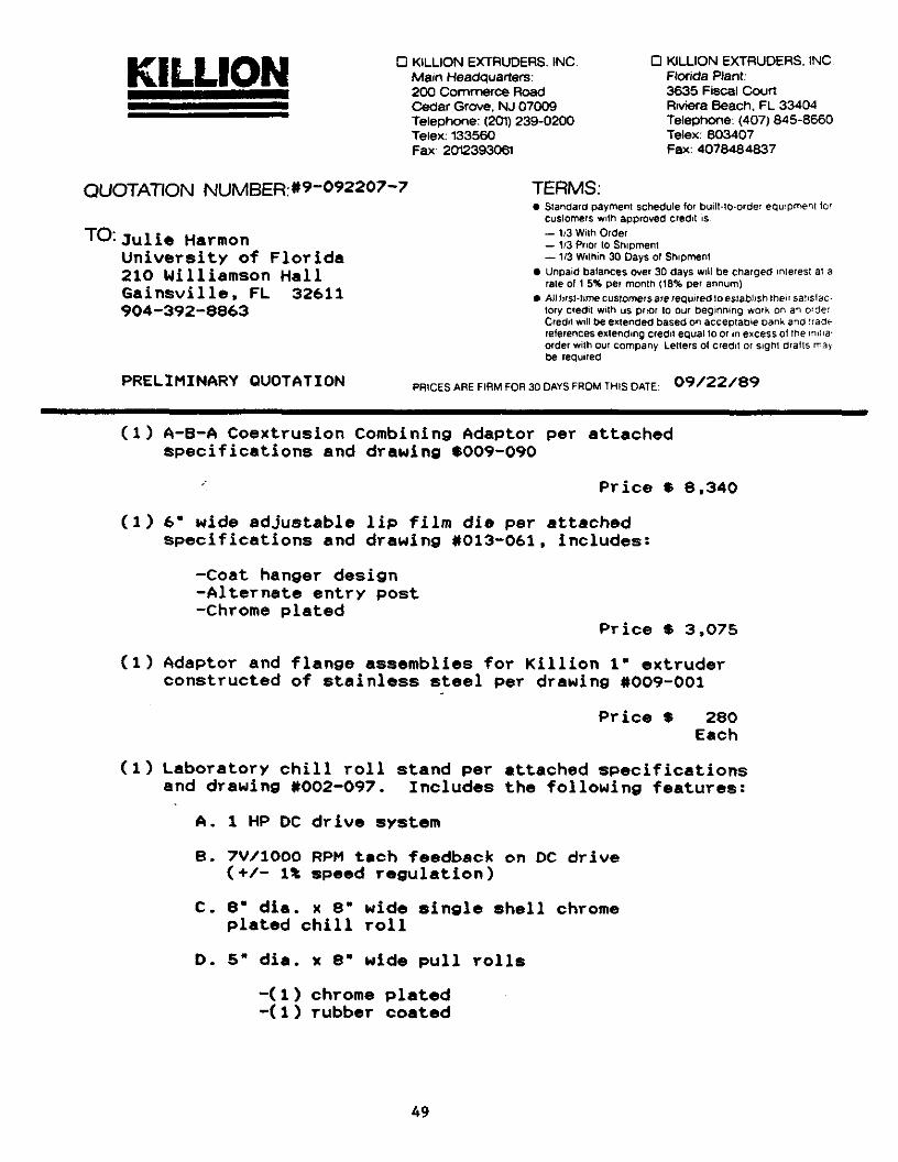
KILLION 0 KILLION EXTRLJDERS. INC. 0 KILLIONJ EXTRUDERS, INC.Main Headquarters: Florida Plant:200 Commerce Road 3635 Fiscal Court
____________________
Cedar Grove, NJ 07009 Riviera Beach, FL 33404Telephone: 201 239-0200 Telephone: 407 845-8660Telex: 133560 Telex: 803407Fax: 2012393061 Fax: 4078484837
QUOTATION NUMBER:*9O922077 TERMS:I Standard payment schedule for built-tO.order equipment to’
customers with approved credit is- 1,3 Wflh OrderJulie Harmon -1/3PriortoShipment
University of Florida - 1/3 Within 30 Days ol Shipment
210 Williamson Hall * Unpaid batances over 30 days wilt be charged interest at arate of 1.5% per month 18% per annum
Ga a nsv ii 1 e , FL 32611 * All f,rsl.tirne cuslomersare required to establish then salistac904-392-8863 tory credit with us prior to our beginning work on an oder
Credil wilt be extended based on acceptable bank and traderelerences extendrng credit equat to or in excess of the initiaorder with our company Letters ot credit or sight drafts maybe required
PRELIMINARY OUOTATION PRICES ARE FIRM FOR 30 DAYS FROM THIS DATE: 09/22/89
1 A-B-A Coextrusion Combining Adaptor per attachedspecifications and drawing *009-090
Price $ 8.340
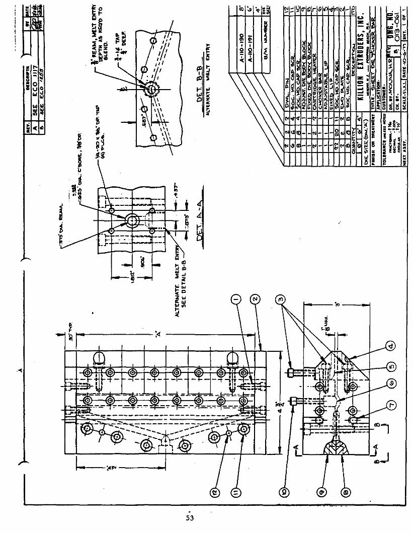
1 6" wide adjustable lip film die per attachedspecifications and drawing *013-061. includes:
-Coat hanger design-Alternate entry post.-Chrome plated
Price $ 3.075
Ci Adaptor and flange assemblies for Killion 1" extruderconstructed of stainless steel per drawing *009-001
Price $ 280Each
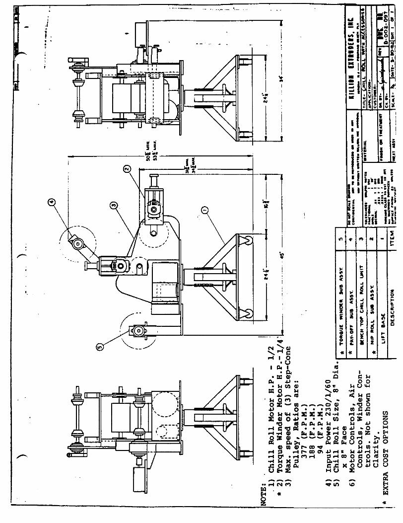
1 Laboratory chill roll stand per attached specificationsand drawing *002-097. Includes the following features:
A. 1 HP DC drive system
B. 7V/1000 RPM tech feedback on DC drive+/- it speed regulation
C. 8" die. x 8" wide single shell chromeplated chill roll
D. 5" dia. x 8" wide pull rolls
-1 chrome plated-Ci rubber coated
49
KILLIONQuotation *9-092207-7 Univ. of Florida Page 2of 2
E. 20 to 1 ratio gear reducer with timing beltdrive. Approximate speed range using 1 to 1ratio belt and pulley set is 12 to 114 PPM
NOTE: Other speed ranges available
Price $11 .300
NOTE: Killion offers a 10% discount off above list pricesto all qualified educational institutions.
DELIVERY DATE: Approx. 8 weeks after receipt of writtenorder and settlement of all pertinent details.
SHIP VIA: Best Way
F.0.B.: Cedar Grove. NJ or Riviera Beach. FL
SIGNED:
____________________________________
Pa ardoneSenior Sales Engineer
This quotation is offered subject to all of the terms and conditions on te reversd SidE Of Pa a 1.
50

*.- I -
NOTE:
* 2
3
4
5
Chill Roll Motor H.P. - 1/2Torque Winder Motor H.P.-1/4Max. speed of 3 Step-ConePulley, Ratios are:
377 F.p.M.188 P.P.M.
94 F.P.M.Input Power 230/1/60Chill Roll Size, 8" Dia. -
x 8" Face *
6 Motor Controls, AirControls, Winder Controls. Not shown forClarity.
* EXTRA COST OPTIONS
tOfiouf WINflE* SUB AflY.
* PM- OPF SUB ASS V.
WelCH ‘TOP C4LL SOLL UNIT
S
4
3
* NIP IOtL BUS ASSY. Z
LIFT SAM I
boa’ its. - -- - -con*tI,M - fl N Sfl - " S
- -, at... ats. -
i..... s... ‘.s SATSRIAI..-‘L i -.
t -CN .i * *
.... . I -.*itu I -
i_a, etaSI fl I.’ ti 1A SCiSS act1it"’Ct!.eti J.y aa
KItLISU 11115115.tICnsa so- r..._ Ste" ‘.4
jilt,. CHILL AA. WITH ACCISSOStIW*ntlcfl.ce-
1fl15tN1 r ç. ItalY! IWL II.I !sr-. 1’ ID-GOt-OS?
-t
n,srfl.PTInw ITEM icati. k 11Y1. 1 IO4aIini I

‘ I L/%._I I L.. *‘..,.
Ifly. I niic.wtmu I *,It IAOOCDflfleS.IL4t,fl A.nni4& ilI Iintee a. ,cotb Lwai. nit
I_A I*ID*w1i41A0010N jana..IgTtatt k ISI
A t4 tfl ArtA Sn 6--ti. 4’S
At#. e- c.i in sa4-Vt. S-’o%4*fA O.eci% Afl
33% -3 -5%
*11..Ddof5U-X3
D-OO4 5Z4-Wt
DCCI. 5&6 .Ci
o C04. 56L.o.ccq. 54..0tC4 -544
CO Not SCALE n-siccoNcIotwTin: ‘icr To .InO.ti. can, - -.
St St"OY’ M-tTiN WILLIOS. sit *Pn.a11 LLION kilO DRS,
ISOWS. MS - *C4 MiACit
"IM
I5
‘4
3
ItII
llceislcae.E ADAPTER
5cc MD. CAP Sce. 141L. V
5CC MD 51LD s ye
tOWCL flN tYj LG
wnHn trI1S
________
NOTE:
C0EESMACWINED WHENftATES A5EM6LED.
t CAeIQIDGE MEATE R5 hVsrUAVE FLEX. ACMOE LFA.
Soc UD CAP SCE. ‘-2o iX,’tSI0
q
8
6
S45
2
C’CVIDWS-OO, Q7
850 MD CAP SCE. t- $
ADAPTER 50. MCLfl
PLATE
CLAMP PLATE LEFTCENTER PLATECLAMP ATt fRI&HT
JDA P’TE R PLATE
ADAPTER
,ENTEE PLAit SHEDAE tJ4 iJO
a-oo- onC-004 -54!SEC &HWJX
NO DCCRtPTION
C- Q4. 543
£004-54A -ooq-oeq
,Ott.ANC,I: Ulititi NOTtO*S.CilOiiAt:ASiOLI. I 30.,cis.L: JI I I tic
.1K1 I I 00$* I 000$
IsItACI CLASS IA iii Ii STALt IiACiiIIiiO ivatACitIu.VACt *‘W*SM ii UiitiflOILJIShIi ifliitb
1 MATERIAL
DNG. kfl
ArPtfC*rtON.TITLE. tt bINIRIC AowrEg
CUSTOMER.
FINISH O TREATMENT OR. v. DWC. NO.c-ooIoco
hint ASS!. scate. NTS losu- Z 21. 64 Issi I Of I
-Amlvi bl$CRIPTh
IA I SEE ECO tillI S. I see EC.Ô ‘ts-S
SvATE
WI’P
nfl. r..-p..MYtRNA’Tt MELT ENThY
KiLLIONttA. itt - POdiRiIiO 1e001 PEA.
flS 5090
MACTOAAL t 14.DECIMAL . tootAHGtA.AR
DR.
/
nsao*: c’eoqt, W.
.%-r v. . ‘tsPa V.C.t.
*‘REAM.ME%t twnvDEPTH AS ttfl toBLEND.
1.I TAP4‘
DEEP.
SEE DETAIL BS
.437-
Ott B-B
OWL .. -.
O%3 ‘-Oc%SCALE .ctj.LJDAt -‘o-a-+FlSsit. OF
1
-I.
Chill Roll Motor H.P. - 1/2Torque Winder Motor H.P.- 1/Max. speed of 3 Step-ConePulley, Ratios are:
377 F.P.M.188 F.P.M.
94 F.P.M.Input Power 230/1/60Chill Roll Size, 8" Dia. -
x 8" Face * TOASUE WINDER SUB ASSY.
6 Motor Controls, AirControls, Winder Controls. Not shown forClarity,
EXTRA COST OPTIONS
* PAY-On SUB ASSY.
WelCH TOP CUI%.L ROES WIlt
5
4
3
* NIP ROLL SUB ASSY. . 2
LIFT BASE
DESCRIPTION flEM
PC NOT 00*41 -COIIfl$IiAt - a a Pici NO - S
- 5._I rns .S. - -
hulls IflIflhls. In.SNOMA 54-.-- - a_N .1
TITLE- MILL m&t. WITH ACttSSO*ttS
APftICSTIOS
CUSTQMIS
I,nn’i TSEATNT NO. iv. p .1 JSIVj IJ ItI ‘. i j-oot-osv
LAST. SCM. -‘
NOTE:1
* 23
45
,aiNaiat S, Notis*.actaAt I Si
, -5t .Al I I I0
ii. i I -.JIPII P AA0$
I_at eta.. .. lit I’ -t- a,tSnO ..ciSt.cS ,Sit. 53 a.flI,’__,.. ,nn..I
rfuIIM
ECLLOE+
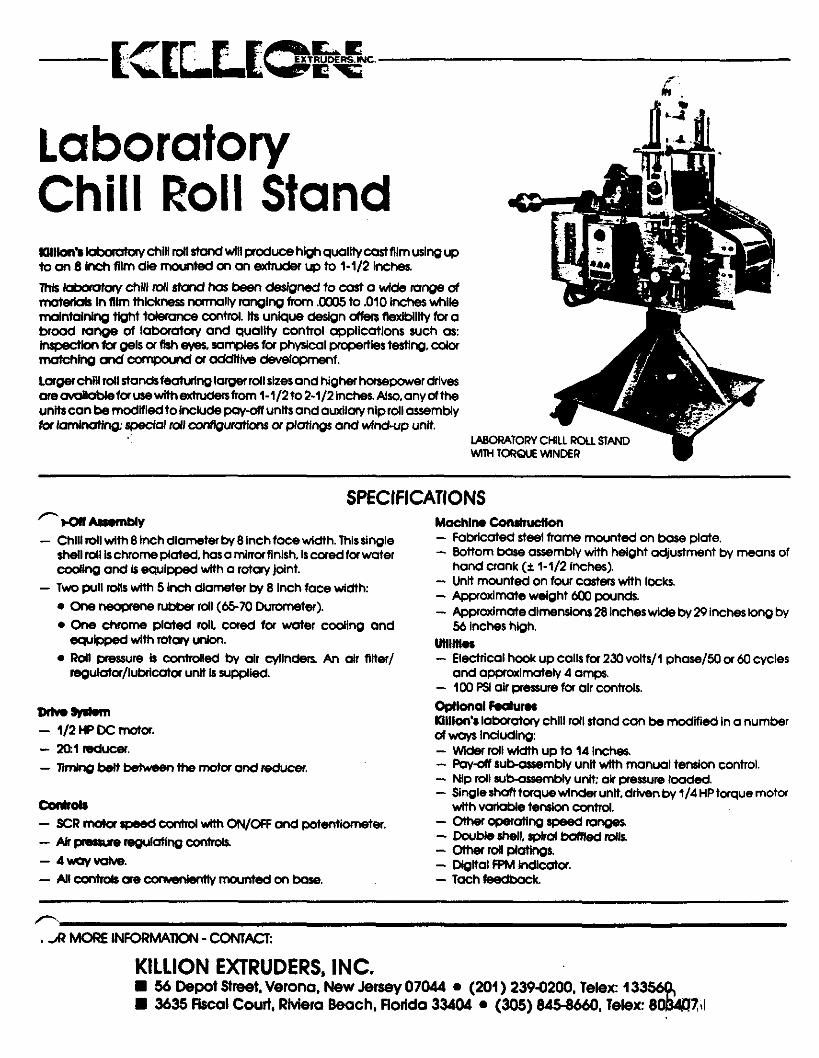
LaboratoryChill Roll StandICIlllon% ld,ocatccy chill roll stand will produce high qualltycastfllm using upto an 8 Inch film die mounted on an extiuder up to 1-1/2 inches.
This Ia’ctory chili loll stand has been designed to cast a wide range ofmatedals In film thickness normally ranging from .S to .010 Inches whilemaintaining tight tolerance control. Its unique design offers fle,dblllty for abroad range of laboratory and quality control applications such as:inspection for gels or fish ma samples for physical properties testing, colormatching and compound or additive development.
Largerchill roll standsfeattslnglarger roll sizes and higher horsepower drivesoreavailable for use with extrudersfrom 1-1/2 to 2-1/2 Inches. Also, any of theunitscon be modified to Include pay-off units and auxllaty nip roll assemblyfor laminating: special roll configurations orplatings and wind-up unit.
SPECIFICATIONS
- Chifi roll wIth 8 inch diameter by 8 lnchfacewldth. This singleshell roll is chrome plated, has a mirrorfinish. is cored for watercooling and is equipped with a rotay joint.
- Two pull rolls wIth 5 Inch diameter by 8 inch face width:e One neoprene rubber roll 66-70 Durometer.B One chrome plated roll, cored for water coding and
equipped with rotary union.S Roll pressure Is controlled by air cllnders. An air filter/
regulator/lubricator unit Is supplied.
n -- 1/2HPDCmotor.- mi reducer.- Pining belt between the motor and reducer.
CoSrols- 3CR motor speed control with ON/OFF and potentiometer.- Air pressure regulating controls.- Awayvolve.- M controls are conveniently mounted on base.
pm
Machin. Construction- Fobricated steel frame mounted on base plate.- Bottom base assembly with height adjustment by means of
hand crank Ci 1-1/2 inches.- Unit mounted on four casters with locks.- Approximate weight 600 pounds.- Approximate dimensIons 28 Inches wide by 29 inches long by
56 Inches high.Utilities- Electrical hook up calls for 230 volts/I phase/SO or 60 cycles
and approxImately 4 amps.- 100 PSI air pressure for air controls.Optional Saturnmillon’s laboratory chill roll stand can be modified in a numberOf ways Including:- Wider roll width up to 14 Inches.- Pay-off sub-assembly unit with manual tension control.-. Nip roll sub-assembly unit air pressure loaded.- Single shaft torque winder unit driven by 1/4 HP torque motor
with vaflable tension control.- Other operating speed ranges- Double shelL spiral baffled rolls- Other roll piatings.- Digital FPM Indicator.- Tach feedback
,R MOQE INFORMA1ON - CONTACT:
KILLION EXTRUDERS, INC.* 56 Depot Street, Verona, New Jersey 07044 * 201 239-0200, Telex: I 33569.a 3635 Fiscal Court. Riviera Beoch1 Hodda 33404 * 305 845-8660, Telex: 803ClI
LABORATORY CHILL ROLl. STANDWITh TORQUEWINDER