proposal form - north dakota
TRANSCRIPT


PROPOSAL FORMNorth Dakota Department of Transportation
Job 028
9/29/2015Rev:
BID OPENING:October 09, 2015
Project:
Type of Work:
Counties: GRAND FORKS and STUTSMAN
Length: 0.0000 Miles
ITS - DYNAMIC MESSAGE SIGNS
IM-9-999(328) (PCN-20806)
Page 8 of 9
TIME FOR COMPLETION:
The undersigned Bidder agrees, if awarded the contract, to prosecute the work with sufficient
forces and equipment to complete the contract work within the allowable time specified as follows:
WORKING DAY CONTRACT: working days are provided. The Department will begin
charging working days beginning or the date work begins on the project site,
NA
CALENDAR DAY CONTRACT:
begins on the project site, whichever is earlier.
COMPLETION DATE CONTRACT:
provides a minimum of
or the date workwill be determined by adding
whichever is earlier.
NA
calendar days are provided. The completion date
N
NA
NA calendar days to NA
The project completion date is . The DepartmentNA
working days. The Department will begin charging workingNA
or the date work begins on the project site, whichever is earlier.days beginning NA
REFER TO SP 103(14) FOR COMPLETION DATES AND RESPECTIVE LIQUIDATED DAMAGES.
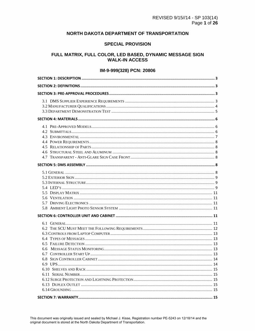
REVISED 9/15//14 - SP 103(14) Page 1 of 26
NORTH DAKOTA DEPARTMENT OF TRANSPORTATION
SPECIAL PROVISION
FULL MATRIX, FULL COLOR, LED BASED, DYNAMIC MESSAGE SIGN
WALK-IN ACCESS
IM-9-999(328) PCN: 20806
SECTION 1: DESCRIPTION ......................................................................................................................... 3
SECTION 2: DEFINITIONS .......................................................................................................................... 3
SECTION 3: PRE-APPROVAL PROCEDURES ................................................................................................ 3
3.1 DMS SUPPLIER EXPERIENCE REQUIREMENTS ..................................................................................... 3 3.2 MANUFACTURER QUALIFICATIONS ....................................................................................................... 4 3.3 DEPARTMENT DEMONSTRATION TEST .................................................................................................. 5
SECTION 4: MATERIALS ............................................................................................................................ 6
4.1 PRE-APPROVED MODELS ..................................................................................................................... 6 4.2 SUBMITTALS ........................................................................................................................................ 6 4.3 ENVIRONMENTAL ................................................................................................................................ 7 4.4 POWER REQUIREMENTS ....................................................................................................................... 8 4.5 RELATIONSHIP OF PARTS ..................................................................................................................... 8 4.6 STRUCTURAL STEEL AND ALUMINUM ................................................................................................. 8 4.7 TRANSPARENT - ANTI-GLARE SIGN CASE FRONT ................................................................................ 8
SECTION 5: DMS ASSEMBLY ..................................................................................................................... 8
5.1 GENERAL .............................................................................................................................................. 8 5.2 EXTERIOR SKIN ..................................................................................................................................... 9 5.3 INTERNAL STRUCTURE .......................................................................................................................... 9 5.4 LED’S ................................................................................................................................................. 9 5.5 DISPLAY MATRIX .............................................................................................................................. 11 5.6 VENTILATION .................................................................................................................................... 11 5.7 DRIVING ELECTRONICS ..................................................................................................................... 11 5.8 AMBIENT LIGHT PHOTO SENSOR SYSTEM ......................................................................................... 11
SECTION 6: CONTROLLER UNIT AND CABINET ........................................................................................ 11
6.1 GENERAL ........................................................................................................................................... 11 6.2 THE SCU MUST MEET THE FOLLOWING REQUIREMENTS .................................................................. 12 6.3 CONTROLS FROM LAPTOP COMPUTER ................................................................................................. 13 6.4 TYPES OF MESSAGES ......................................................................................................................... 13 6.5 FAILURE DETECTION ......................................................................................................................... 13 6.6 MESSAGE STATUS MONITORING ....................................................................................................... 13 6.7 CONTROLLER START UP .................................................................................................................... 13 6.8 SIGN CONTROLLER CABINET ............................................................................................................. 14 6.9 UPS ................................................................................................................................................... 14 6.10 SHELVES AND RACK ........................................................................................................................ 15 6.11 SERIAL NUMBER .............................................................................................................................. 15 6.12 SURGE PROTECTION AND LIGHTNING PROTECTION ........................................................................... 15 6.13 DUPLEX OUTLET ............................................................................................................................. 15 6.14 GROUNDING ...................................................................................................................................... 15
SECTION 7: WARRANTY.......................................................................................................................... 15
This document was originally issued and sealed by Michael J. Kisse, Registration number PE-5243 on 12/18/14 and the original document is stored at the North Dakota Department of Transportation.

REVISED 9/15//14 - SP 103(14) Page 2 of 26
7.1 SPARE PARTS ...................................................................................................................................... 16
SECTION 8: REFERENCES ........................................................................................................................ 16
SECTION 9: GENERAL NTCIP REQUIREMENTS ......................................................................................... 17
9.1 INFORMATION LEVEL ........................................................................................................................ 17 9.2 MANDATORY CONFORMANCE GROUP ............................................................................................... 18 9.3 OPTIONAL CONFORMANCE GROUPS .................................................................................................. 18 9.4 APPLICATION LEVEL ......................................................................................................................... 20 9.5 TRANSPORT LEVEL ............................................................................................................................ 20 9.6 SUBNETWORK LEVEL ........................................................................................................................ 20
SECTION 10: SOFTWARE DOCUMENTATION........................................................................................... 20
SECTION 11: CONTROL SOFTWARE ........................................................................................................ 21
11.1 DMS CONTROL ............................................................................................................................... 21 11.2 COMMUNICATIONS .......................................................................................................................... 21 11.3 MESSAGE LIBRARY ......................................................................................................................... 21 11.4 SYSTEM EVENT LOGGING ................................................................................................................ 21
SECTION 12: TECHNICAL ASSISTANCE ..................................................................................................... 22
SECTION 13: CONSTRUCTION DETAILS ................................................................................................... 22
13.1 DMS SUPPORTING STRUCTURES AND FOUNDATIONS ...................................................................... 22 13.2 SUBMITTALS .................................................................................................................................... 22
SECTION 14: TESTING REQUIREMENTS ................................................................................................... 23
14.1 DESIGN APPROVAL TEST ................................................................................................................. 24 14.2 STAND ALONE TEST ........................................................................................................................ 24 14.3 72 HOUR TEST ................................................................................................................................. 25 14.4 90 DAYS TEST .................................................................................................................................. 25
SECTION 15: FINAL SYSTEM ACCEPTANCE .............................................................................................. 25
SECTION 16: TRAINING........................................................................................................................... 26
SECTION 17: METHOD OF MEASUREMENT ............................................................................................. 26
SECTION 18: BASIS OF PAYMENT ........................................................................................................... 26
18.1 LIQUIDATED DAMAGES ................................................................................................................... 26

REVISED 9/15/14 - SP 103(14)) Page 3 of 26
Section 1: Description The work under this item shall consist of furnishing, installing, and testing walk-in, full-matrix, color, Light Emitting Diode (LED) based Dynamic Message Signs (DMS) at the locations designated on the plans and in accordance with the Contract Documents. The DMS’s shall be installed on the proposed sign structures shown in the plans. The DMS’s shall include operational software, and all cabling and mounting hardware. Also to be furnished, but specified elsewhere, electric utility metering equipment, ground mounted controller cabinets, and communication hardware and software required for a fully operating DMS. The proposed DMS shall be a Walk-in LED full matrix sign utilizing RGB full color, 20mm pixel pitch and shall be capable of displaying 3 lines of text, 17 characters per line, 18-inch characters, in 23X15 font, 96 by 336 pixel layout with 30° viewing angle, pure LED characters and minimum housing dimensions of 7 feet high, 24 feet wide, and 4 feet deep. Access doors shall be provided in each end of the cabinet to allow emergency egress. The DMS’s shall be used to display traffic advisory messages to inform motorists of current road conditions along their route. The advisory messages shall be transmitted from the Department Maintenance Division and/or District offices using Intelligent Control operating software. The DMS shall comply with current National Transportation Communications for ITS Protocol (NTCIP) guidelines and standards.
Section 2: Definitions
The following terms shall apply within the scope of this procurement specification:
• DMS – Dynamic message sign. A type of DMS that is fully programmable such that the content of its messages are fully changeable remotely and electronically.
• FSORS – An NTCIP term meaning “Full, Standardized Object Range Support.” See NTCIP standards for additional information.
• Management System – A computer system used to control an NTCIP component. This includes any laptop software used for field control as well as the central control software.
• NTCIP Component – A DMS or a Management System. • NTCIP System – A Management System and DMSs controlled by the Management System. • Response Time – The time to prepare and begin transmission of a complete response containing the
requested Application Layer information. This is measured as the time from receipt of the closing flag of the request to the transmission of the opening flag of the response when the device has immediate access to transmit.
Section 3: Pre-Approval Procedures 3.1 DMS Supplier Experience Requirements To be valid for these experience requirements, a walk-in LED DMS must be a State Highway or Interstate Highway, permanently mounted, overhead, LED dynamic message full matrix sign in accordance with Section 1.0. Non-LED DMS, hybrid DMS, lift-face DMS, non-highway DMS, portable DMS, indoor DMS, and commercial DMS will not satisfy these experience requirements. The DMS Supplier shall have the following, under the current corporate name.
3.1.1 Six (6) years’ experience in the design and manufacture of State Highway or Interstate Highway, permanently mounted, overhead, walk-in dynamic message signs and central

REVISED 9/15/14 - SP 103(14)) Page 4 of 26
control systems installed in freeway service. These 6 years of experience shall include the complete design and manufacture of all aspects of the dynamic message signs, including the electronic hardware, software and sign housings.
3.1.2 Walk-in and front access LED DMS that have been installed, successfully operating and owned by five (5) different State Departments of Transportation, City Highway Department, or County Highway Department for a period of no less than two (2) years.
3.1.3 Fifty (50) NTCIP-compliant LED DMS that are installed, successfully operating and owned by either State Departments of Transportation, City Highway Department, or County Highway Department. These NTCIP-compliant LED DMS must be permanently mounted, outdoor, roadway, LED DMS that are remotely controlled by an NTCIP compliant central computer.
3.1.4 NTCIP-compliant LED DMS that is installed, successfully operating and owned by ten (10) different agencies. These agencies must be either State Departments of Transportation, City Highway Department, or County Highway Department. These NTCIP-compliant LED DMS must be permanently mounted, outdoor, roadway, LED DMS that are remotely controlled by an NTCIP compliant central computer.
3.1.5 A walk-in and rear access LED DMS NTCIP-compliant system that has been installed, successfully operating and owned by a State Department of Transportation for a period of no less than two (2) years. This system must include an NTCIP-compliant DMS central control system and a minimum of five (5) NTCIP-compliant LED DMS. The software for the NTCIP-compliant DMS central control system and the firmware for NTCIP-compliant LED DMS must have successfully passed an NTCIP test that was administered by an industry-accepted, independent company that was contracted by this State Department of Transportation to perform this test. The NTCIP-compliant DMS central control server software must be the primary DMS control and monitoring application, must be installed on a server in the Department of Transportation’s traffic operations center, must simultaneously and remotely control and monitor multiple NTCIP-compliant signs, and must allow multiple clients to simultaneously and remotely connect to the server for sign control and monitoring.
3.1.6 NTCIP-compliant LED DMS that successfully passed NTCIP tests performed by industry-accepted, independent companies that were contracted by a State Department of Transportation to perform these tests.
3.2 Manufacturer Qualifications ISO 9001:2008 Requirements The company that designs and manufactures the LED DMS shall be currently ISO 9001:2008 certified as of the bid date for this project and shall have received its ISO 9001:2008 certification a minimum of one years prior to the bid date for this project. The scope of this company’s ISO 9001:2008 certification shall be for the Design, Manufacture, Installation, Maintenance and Sales of Variable Message Sign Systems. The facility where this company actually designs and manufactures the LED VMS shall be ISO 9001:2008 certified. This company, this scope and the address of this facility shall all be listed on the ISO 9001:2008 certificate. This ISO 9001:2008 certificate shall be provided with the bid. The name, phone number and address of both the Authorized ISO 9001:2008 Registrar that certified this company and the Authorized ISO 9001:2008 Accreditation Body that accredited this Registrar shall be provided with the bid. Failure to fully comply with these requirements and to provide all this information will cause this company's equipment and software to be rejected. ISO 9002 and ISO 9003 certifications are not adequate and do not meet this requirement.

REVISED 9/15/14 - SP 103(14)) Page 5 of 26
Welding All welding shall be by an inert gas process in accordance with the American Welding Society (AWS) Standards, 2003 ANSI/AWS D1.2/D1.2M Structural Welding Code for Aluminum. The LED DMS manufacturer’s welders and welding procedures shall be certified by an ANSI/AWS Certified Welding Inspector to the 2003 ANSI/AWS D1.2/D1.2M Structural Welding Code for Aluminum. Proof of certification of all the LED DMS manufacturer’s welders and applicable welding procedures shall be supplied with the submittals. The name, phone number and address of the ANSI/AWS Certified Welding Inspector that certified the LED DMS manufacturer’s welders and procedures shall also be provided with the submittals.
3.3 Department Demonstration Test A non-approved DMS supplier shall supply a letter requesting pre-approval in accordance with Section 3.1. The non-approved DMS supplier shall contact the Department ITS Engineer:
ITS Engineer 608 East Boulevard Ave
Bismarck, ND 58505-0700 (701)328-4274
The non-approved DMS supplier shall include references, so experience can be verified. The non-approved DMS supplier shall be responsible for conducting the Department Demonstration test, at the direction of Department. The non-approved DMS supplier shall pay for all expenses for presenting and testing any representative DMS unit according to Section 3.3.3 of this specification. All equipment must pass the following individual tests:
3.3.1 Examination Tests Each piece of equipment shall be examined carefully to verify that the materials, design, construction, markings and workmanship comply with the requirements of the Specification.
3.3.2 Continuity Tests The wiring shall be checked to determine conformance with the requirements of the appropriate paragraphs in the Specifications.
3.3.3 Operational Test Equipment functionality will be thoroughly tested to verify complete compliance with all areas of these specifications. Device Tester from Intelligent Devices, Inc. shall be used to test for compliance to the NTCIP requirements, using the Department DMS Device Tester Scripts Rev. No 1.8.1 dated September 2003. The DMS unit will be exercised over a two day period by Device Tester. Any minor deficiencies identified during the first day of testing may be corrected by the Supplier and retested during the second day. Device Tester will be run unmanned overnight after the first day of live testing to test whether the supplier’s equipment is robust and reliable. Department will provide space at the Department’s Bismarck District Office (218 Airport Road, Bismarck, ND 58504) within a fenced area. Power required to conduct the test is the supplier’s responsibility.

REVISED 9/15/14 - SP 103(14)) Page 6 of 26
Section 4: Materials
4.1 Pre-Approved Models
VF-2020-96x336-20-RGB 20mm, manufactured by,
DAKTRONICS, Inc. P.O. Box 5128 331 32nd Avenue Brookings, SD 57006 Phone (605)697-4300
VMSLED-W-20F-96x336-RGB-I 20 mm, manufactured by,
Skyline Products, Inc. 2903 Delta Drive Colorado Springs, CO 80124 Phone (719)494-4871
or Pre-Approved equal. To become Pre-Approved, a DMS supplier shall submit sign(s) for testing according to Section: Pre-Approval Procedures.
4.2 Submittals The DMS Supplier must prepare and submit detail shop drawings in accordance with Section 13.2.2 of this specification for the signs indicating types of materials proposed for each component of the signs, parts lists, assembly techniques, layout of all display elements, and wiring schematics. Also required is a drawing of the cabinet structural attachment locations and details with calculated static and dynamic forces indicated. These drawings must be submitted to the department for review and approval within 30 calendar days from the date of the order of the DMS, and prior to fabrication of any sign. Parts lists must include circuit and board designation, part type and class, power rating, component manufacturer, and mechanical part manufacturer. As part of the submittals for the DMS assembly, the DMS Supplier must submit an engineering drawing illustrating the DMS character set including 26 upper case letters, 10 numerals, a dash (-), a plus sign (+) and slash (/). The DMS Supplier must also submit complete technical information, shop drawings, photographs, graphs, circuit diagrams, instruction manuals, security provisions, and any other necessary documents to fully describe the DMS and associated equipment.
REVISED 9/15/14 - SP 103(14)) Page 7 of 26
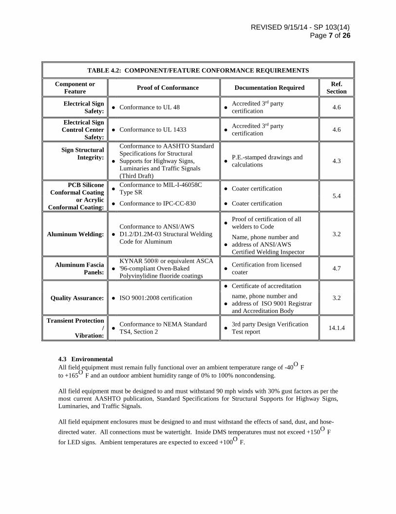
TABLE 4.2: COMPONENT/FEATURE CONFORMANCE REQUIREMENTS
Component or Feature Proof of Conformance Documentation Required Ref.
Section
Electrical Sign Safety: ● Conformance to UL 48 ● Accredited 3rd party
certification 4.6
Electrical Sign Control Center
Safety: ● Conformance to UL 1433 ● Accredited 3rd party
certification 4.6
Sign Structural Integrity:
●
Conformance to AASHTO Standard Specifications for Structural Supports for Highway Signs, Luminaries and Traffic Signals (Third Draft)
● P.E.-stamped drawings and calculations 4.3
PCB Silicone Conformal Coating
or Acrylic Conformal Coating:
● Conformance to MIL-I-46058C Type SR ● Coater certification
5.4 ● Conformance to IPC-CC-830 ● Coater certification
Aluminum Welding: ● Conformance to ANSI/AWS D1.2/D1.2M-03 Structural Welding Code for Aluminum
● Proof of certification of all welders to Code
3.2 ●
Name, phone number and address of ANSI/AWS Certified Welding Inspector
Aluminum Fascia Panels: ●
KYNAR 500® or equivalent ASCA '96-compliant Oven-Baked Polyvinylidine fluoride coatings
● Certification from licensed coater 4.7
Quality Assurance: ● ISO 9001:2008 certification
● Certificate of accreditation
3.2 ●
name, phone number and address of ISO 9001 Registrar and Accreditation Body
Transient Protection /
Vibration: ● Conformance to NEMA Standard
TS4, Section 2 ● 3rd party Design Verification Test report 14.1.4
4.3 Environmental All field equipment must remain fully functional over an ambient temperature range of -40O F to +165O F and an outdoor ambient humidity range of 0% to 100% noncondensing. All field equipment must be designed to and must withstand 90 mph winds with 30% gust factors as per the most current AASHTO publication, Standard Specifications for Structural Supports for Highway Signs, Luminaries, and Traffic Signals. All field equipment enclosures must be designed to and must withstand the effects of sand, dust, and hose-directed water. All connections must be watertight. Inside DMS temperatures must not exceed +150O F for LED signs. Ambient temperatures are expected to exceed +100O F.

REVISED 9/15/14 - SP 103(14)) Page 8 of 26
4.4 Power Requirements The incoming power to the service cabinet and SCU must be 120 VAC or 120/240 VAC, 60 Hz. The total power requirement for the signs and SCU must not exceed 6000 watts during the operation of a user-selected message with all 54 characters being displayed to the public. An average of 160 pixels per character will be used for calculation verification.
4.5 Relationship of Parts The DMS assembly must consist of a DMS cabinet, DMS contents including: mounting brackets, control cables, presentation medium, photo-sensing equipment, transparent anti- glare cover, heat and ventilation system, conduit, and fittings. In addition, the SCU, must be installed in a ground-mounted cabinet with the following contents: modem, RS232 port for laptop computer connection, local controller with software, current electrical diagram, power and electrical termination blocks and power distribution center as required by the technology. The DMS assembly must also contain the following assemblies: Waterproof local/remote switch, Local control LED indicator, Sign to ground voice communications RJ-11 jack, RS-232 connection for the notebook computer, latching handle with padlock option. The SCU cabinet must have a retractable shelf and drawer suitable for the notebook computer to rest on.
4.6 Structural Steel and Aluminum Cabinets must be constructed of sheet aluminum or extruded aluminum meeting the requirements of 6.8. Rod, Bar, and extruded aluminum must be Type 6061-T6 or equivalent. Stainless steel sheet must be annealed or one-quarter-hard complying with the ASTM Designation: A666 for Type 304, Grades A or B, stainless steel sheet. All cold rolled steel must be plated. All plating must be either cadmium plating meeting the requirements of Federal Specification QQ-P-416C, Type 2 Class 1 or zinc plating meeting the requirements of Federal Specification QQ-Z-325B, Type 2 Class 1. Cold rolled steel sheet, rod, bar, and extruded must be Type 1018/1020. All materials must be new, corrosion resistant and in strict accord with these specifications and the exhibits that accompany them.
The VMS assembly shall be listed by an accredited 3rd party testing organization for conformance to Underwriters Laboratories (UL) standards 48 (Standard for Electric Signs) and 1433 (Control Centers for Changing Message Signs). Proof of this conformance shall be provided with submittal materials.
4.7 Transparent - Anti-Glare Sign Case Front The sign face must be manufactured of clear polycarbonate sheets of GE Lexan Type XL10 with a KYNAR 500 coated aluminum mask over a clear glazing, AutoGlas Tuffak XL or approved equal. The aluminum mask of each panel shall be painted black and shall contain an opening for each pixel. Openings shall be large enough to not block any portion of the viewing cones of the LED’s. For substitutes, the DMS Supplier must submit one (1) sample 12 inches x 12 inches of the proposed material together with a description of the materials attributes to the Engineer for review and approval.
Section 5: DMS Assembly 5.1 General The DMS must be of the LED type.

REVISED 9/15/14 - SP 103(14)) Page 9 of 26
The DMS equipment must consist of the following:
• Dynamic Message Sign and side access walk-in Sign Cabinet. • The SCU and associated equipment and accessories described herein to be provided at the DMS
site. • The SCU cabinet. • Control and power cabling from the SCU and the signs.
A DMS representative must be present and coordinate the connection work between the DMS case and the SCU with the construction contractor, and must furnish certification that installation methods meet approved manufacturer’s requirements. The DMS controller must be capable of displaying a message downloaded from the central communications location Department Maintenance Division and/or District offices, a message downloaded from the Notebook Computer or a pre-stored message in the SCU’s own memory. The SCU must perform through the sign electronics and the SCU must process and format a status message for transmission to the central communication location. The DMS must include all components and parts required to provide a complete unit including DMS sign, DMS sign case, display matrix, ventilation, electronics, and photo sensor(s). All sign cases must be dust-proof and watertight. The sign case must be designed for attachment to its associated overhead sign support structure. All welding must be performed in accordance with ANSI/AWS D1.2 Structural Welding Code-Aluminum (2003). All sign cases must be constructed of unfinished, welded aluminum, except the matte black front aluminum face. All seams must be continuously welded. DMS must be fitted with hubs or knockouts for conduit. The characters must be formed from light and must be readable without the aid of reflective or non-reflective disks. Reflective techniques must not be used to increase target value and legibility distance.
5.2 Exterior Skin The exterior skin of the housing will be 5052-H32 aluminum alloy sheet 0.125 inches minimum thickness. The number of seams shall be kept to a minimum. All exterior seams and joints shall be sealed to form a rain and weather tight enclosure. The skin material shall be stitch welded to the internal structural members to form a unitized structure.
5.3 Internal Structure The interior housing structural members shall be 6061-T6 and 6063-T5 aluminum alloy extrusions.
5.4 LED’s Each pixel shall contain three strings of LEDs. Each pixel shall contain a Red, Green, and Blue LED, each being its own string. The pixel strings shall be powered from a regulated DC power source and the LED current shall be maintained to maximize life of the pixel. The failure of an LED in one string within a pixel shall not affect the operation of any other string or pixel. Pixel power drawn from the DC supplies shall not exceed 1.5 watts per pixel, including the driving circuitry. The LEDs shall be individually mounted directly to a printed circuit board and shall be easily replaceable and individually removable using conventional electronics repair methods.

REVISED 9/15/14 - SP 103(14)) Page 10 of 26
Sign brightness shall beet NEMA TS4-2005, Section 5, (12,400 cd/m2 minimum white brightness.) The LED drive current – Red less 30mA, Blue & Green less than 15mA. Each pixel must be comprised of a minimum of three LED’s at 20 milliamps or less. The DMS supplier must provide batch numbers to show that the LED’s are rated for the brightness specified, and the average light intensity must be within 1.0 candela per pixel. All pixels must have equal color and on-axis intensity. LED’s must not emit light except when a message has been user-commanded. All primary DMS components must be easily removable with common hand tools. The DMS display module and lens must be accessible and maintainable from inside the sign case. Red LED’s must be Aluminum Indium Gallium Phosphide-type (AlInGaP) LED’s, Green and Blue LED’s must utilize InGaN technology, with a viewing cone of 30 degrees. Wavelengths must meet chromaticity requirements and must be approximately 615nm – 635nm for red LED’s, 520nm – 535nm for green LED’s and 464nm - 470nm for blue LED’s. LED’s must be rated for 100,000 hours MTBF under continuous operation at 20 ma. Light output degradation must be less than 50% after 100,000 hours. Cone visibility must be declared by the DMS Supplier. Since there are numerous options of LED visibility cones, the DMS Supplier must prove that legibility requirements are met prior to installation. Sign cabinet must be ventilated sufficiently to allow the LED’s to operate in the LED manufacturer’s recommended temperature range. In addition, the DMS must meet the following requirements: • Printed Circuit Boards Printed Circuit Board (PCB) design shall be such that components may be
removed and replaced without damage to boards, traces or tracks. Only FR-4 0.062 inch minimum thickness material shall be used. Inter component wiring shall be copper clad track having a minimum weight of 2 ounces per square foot with adequate cross section for current to be carried. Jumper wires will not be permitted, except from plated-through holes to component. The maximum number of jumper wires allowed per circuit board is two. All Printed Circuit Boards (PCBs) shall be completely conformal coated with a silicone resin conformal coat or acrylic based conformal coating. The material used to coat the PCBs shall meet the military specification: MIL-I-46058C Type SR and IPC-CC-830. All PCBs shall be finished with a solder mask and a component identifier silk screen.
• Sign Mounting. The details of the sign mounting must be coordinated between the DMS supplier
and the construction contractor, including attachment point locations and details and gravity and wind loading locations and magnitudes.
• Sign Legibility. The sign display must be clearly visible from a distance of 1,100 feet within a 30
degree cone centered about the axis under normal atmospheric conditions and under any lighting condition, using 18 inch high characters.
• Writing Speed. Writing speed must appear to write the entire sign instantaneously and must be 80
cps, minimum. • DMS Grounding. The DMS Supplier must provide lugs for grounding the DMS to the DMS
structure.

REVISED 9/15/14 - SP 103(14)) Page 11 of 26
5.5 Display Matrix The display must be a full matrix design. Characters forming words must be readable by a person with 20/20 corrected vision within a range of 100 to 1,100 feet in advance of the sign at an eye height of 1.067 m (3.5 feet) within a 30 degree cone of vision about the optical axis.
5.6 Ventilation All sign cases must be equipped with a positive ventilation system. Changeable filtration devices must be provided at drain holes and at all points where air enters the enclosure. The sign enclosure must not permit temperatures inside the enclosure to exceed +135O F. Air conditioning must not be permitted. Heat tape or heater fans must keep the front face from condensation. The heat tape or heaters must be automatic and have the ability to be controlled by the controller and controllable remotely from either the central computer or the laptop computer connected at the SCU.
5.7 Driving Electronics The driving electronics must generate the signals to the devices controlling the pixels to be illuminated. These signals must be based on commands received from the SCU.
5.8 Ambient Light Photo Sensor System The DMS must incorporate a menu of changing the lighting level provided by the LEDs automatically in response to ambient lighting conditions as detected by the photocell, and remotely in response to commands received from the SCU. The photocells must be positioned to sense in three directions (behind the sign, in front of the sign, and below the sign). The sign controller shall monitor the photo cell circuits in the sign and convert the measured light intensity into the desired pixel brightness. The photo circuit readings shall be correlated with a brightness table in the sign controller. The brightness table shall have a minimum of 248 brightness levels. Each sign shall have its own, independent brightness table. The brightness table in each individual sign controller shall be locally downloadable and can be customized according to the requirements of the installation site. These devices must direct the Sign Controller to modify the intensity of the light produced by the pixel elements. The mounting devices for the photoelectric cells must allow full adjustment of the cell orientation. The photoelectric cells must be located such that they are easily accessible for maintenance. If the photocell fails, the sign must remain in the normal brightness mode and an error message must be sent to the SCU. The SCU must transmit the failure state back to the central control location.
Section 6: Controller Unit and Cabinet 6.1 General The SCU and its cabinet must contain all equipment required to control the DMS. The SCU and sign controller cabinet must fulfill the following functions:
• Control all signs functions. • Store messages. • Meet all power supply requirements. • Monitor signs status. • Communicate with the central computer system using the specified protocol.
REVISED 9/15/14 - SP 103(14)) Page 12 of 26
The sign controller assembly and all major components must conform to the requirements of paragraphs 2.1.12, and 2.1.13 of NEMA Standards Publication TS-1 1998, or equivalent MIL specifications. The sign controller cabinet must be UL labeled or listed. The sign controller assembly and all major components must withstand transients normally experienced on AC power lines and conform to the requirements of paragraph 2.1.6.1, 2.1.6.2, 2.1.8, 2.1.12, and 2.1.13 of NEMA Standards Publication TS-1, 1988, or equivalent MIL specifications. The Contractor must furnish one (1) SCU (Type 2070 or PC based controller) and cabinet to the DMS site. This controller must be an integral unit containing a dedicated power supply.
6.2 The SCU Must Meet the Following Requirements
6.2.1 Controller Address A unique address must be assigned to the SCU. All commands from the central control location to this sign must be prefaced with this address. The SCU must compare this received address with the assigned address and must accept the command only if the addresses match.
The address must be readily changeable through the DMS controller keypad or through changing jumpers in the control cabinet.
6.2.2 Message Storage Capacity The SCU must store a minimum of sixteen (16) messages of 128 characters each in non-volatile random access memory (RAM). Each of the messages must be addressable from the central control location through the communications network. The sixteen (16) messages must also be addressable via the front panel control switches of the SCU.
6.2.3 DMS Controller Front Panel Controls and Displays The front panel of the SCU must have the following clearly labeled switches:
• On/Off Switch. This switch must control the power to the DMS and the controller. It may
be located elsewhere in the cabinet with the approval of the Engineer.
• Local/Remote Switch. In the Local position, control of the sign must be by the local message select or diagnostic switches located on the SCU front panel. In the Remote position, control of the sign must be by messages received from the central control location.
• Message Selection Switch. Message Selection Switches must be capable of selecting
any one of the sixteen (16) messages stored in the SCU. This may also be accomplished by using the front keypad of the controller.
Diagnostics must be performed through the SCU Test Equipment laptop computer. On the front panel of the SCU, a minimum of sixteen (16) messages must be directly assigned through three position switches. The message preprogrammed for each position must be found on a plasticized card stored in the SCU. The front panel must also be able to display the current lamp status; LED’s may be used. If LED’s are used, the LED’s must have a minimum 100,000 hour life and must be amber or green in color with a minimum 0.3 candela brightness.
The front panel of the DMS controller must have the following displays: Controller on Number of message displayed

REVISED 9/15/14 - SP 103(14)) Page 13 of 26
Error fault detected along with an indication of type of error or fault
6.3 Controls from Laptop Computer The SCU must have a separate serial port for connection with the laptop computers. This port must allow field personnel to emulate the central command and monitor functions via the laptop computers. Software must permit simulation of all DMS commands without actually implementing the displays on the DMS.
6.4 Types of Messages The DMS, with SCU, must display the following three types of messages: 1. Static Message 2. Blinking Message Alternating Messages: A selected portion of the chosen sign must display two messages alternately with a repetition interval from one to ten seconds. The duration of each message displayed must be independently selectable in 0.5 second increments.
6.5 Failure Detection The SCU must detect the following failures and report them to the remote controller and notebook computer:
• Power supply monitor circuitry must be provided to detect power failure • The SCU must detect data transmission errors by performing longitudinal redundancy checks and
parity checks on all transmissions received • The SCU must monitor the data in the communications network and must detect
communications failure in the absence of data for a predetermined period of time • Photocell failure • Uninterruptible Power Supply (UPS) failure and battery • Environmental limit failure
6.6 Message Status Monitoring The SCU must transmit to the central control location a return message whenever it received a valid transmission and when it is being addressed. The return message must be in ASCII or NTCIP and the format must be selected by the Supplier subject to the Engineer’s approval. The message format, in general, must contain the sign address, sign message being displayed, mode of operation, contents of any message stored in memory if required from the central control location, current sign illumination level, cabinet temperature, UPS status, power supply voltage level(s), battery status, and the presence and type of failures detected.
6.7 Controller Start Up After power is turned on, the SCU must retain the displayed message until a command to display a different message is received from the central control location or from the control switches on the SCU front panel. After a power outage of any duration, the DMS must automatically return a command condition it was maintaining prior to losing power. Any message being displayed prior to the loss of power must return without any input required from either the central controller or local controller.
REVISED 9/15/14 - SP 103(14)) Page 14 of 26
6.8 Sign Controller Cabinet The cabinet and door must be designed for the most current AASHTO publication, Standard Specifications for Structural Supports for Highway Signs, Luminaries, and Traffic Signals for wind loading of 120 mph with 30% gusts. Easy access to all cabinet equipment must be provided. If access is required to the backside of any components in the cabinet then rear cabinet doors must be provided. All cabinet doors must withstand a 200 lb. vertical load applied anywhere on the door. Each door must be provided with a latching handle with padlocking in the closed position. The integral door lock must be latching handle with lock where the key is removable only in the locked position. All locks must be keyed alike. The Contractor must supply two (2) lock keys for each sign cabinet installed. A removable air filter must be housed behind the door vents. The filter must be pleated paper filter with outside dimensions of 10 inches by 10 inches by 0.88 inches. The doors must have catches to hold the doors open at 90 and 135 degrees. Doors must be gasketed in channels or L brackets with a 0.375 inches or 3/8” gasket made of non-absorbent material and must maintain its resiliency after long-term exposure to the outdoor environment. Each cabinet must be supplied with the following as a minimum:
• Removable pleated paper air filter • SCU and DMS components required to be in the cabinet • Fans and thermostat • Light convenience outlets - two (2) each • UPS • Surge Protection and lightning protection • Circuit Breaker, Power Input Junction Terminal • Termination panel and terminal blocks • Harnesses and connectors • Provisions for grounding by Construction Contractor • Installation and mounting harnesses • Florescent lamp at top of cabinet with door switch actuation door • Cabinet label • EIA equipment rack with adjustable shelves as required • Space reserved for spread spectrum transceiver or fiber optic modem. • Cabinet electrical diagram and drawing storage • Cabinet weatherproofing • Cabinet doors with lock and keys • Pull-out drawer and shelf, mounted on ball-bearing slides capable of supporting 20 pound test
equipment The SCU cabinet must be constructed of mill finish aluminum. The SCU cabinet must be NEMA 3R, or NEMA 4 rated and all seams must be continuously welded. The cabinet must be capable of being located as far as 200 feet away from the DMS structure and must meet the most current AASHTO publication, Standard Specifications for Structural Supports for Highway Signs, Luminaries, and Traffic Signal for Roadside Design Guide requirements.
6.9 UPS A UPS must be provided to allow the sign controller to notify the central controller when an improper power condition exists at the DMS for longer than 30 seconds. The UPS must be UL listed and CSA/cUL certified and meet the following minimum requirements:
• Communications port (DB-9 connector) utilizing contact closures • 250 VA minimum outputs to allow for 10 minutes of sign controller operation during power
outage

REVISED 9/15/14 - SP 103(14)) Page 15 of 26
• Battery Back-up operation, low runtime remaining, and overload alarms • Input power: 120 ±15VAC, 60 ±3Hz • Automatic output protection (over current, short circuit, and over voltage) • Operating environment of 32O F to 104O F, 0 - 95% relative humidity
6.10 Shelves and Rack Shelf space must be per Manufacturer recommendation. The cabinet must contain a 19 inches EIA rack. The angles must comply with EIA RS-310B. The cage must be retractable or must be bolted at 4 points both top and bottom to the cabinet via the housing cage supports and associated spacers.
6.11 Serial Number Cabinets must be supplied with a serial number unique to the Manufacturer. The number must be displayed inside the cabinet in the upper right hand sidewall.
6.12 Surge Protection and Lightning Protection Power line surge protectors must be installed between both line conductors and equipment ground. All conductors entering and leaving the cabinet must be protected by surge protectors and lightning arresters. Data lines between the SCU and the sign case must also contain surge protection unless data line is fiber optic. Power line surge protection (an example is GPTS 120 TLC 20P or EDCO 1210 SHA) must conform to the following requirements:
• Peak surge current occurrences 20 minimum • Peak 8x20 msec wave shape 20K amps • Clamp voltage at 20K amps 250 maximum • Response V < 250 during all portions of surge • Max. current at 120 VAC, 60Hz 10 amps • Series inductance 200 microhenries • Temperature NEMA TS-1 • Maximum Dimensions 3.25 x 7.25 x 2.5
Each cabinet must be equipped with one or more radio interference filters in the power line surge protector. The filter must provide attenuation of at least 50 Db over a range of 50 kHz to 20 MHz
6.13 Duplex Outlet A 120 VAC convenience outlet must be provided with integral ground fault interrupt and must be protected by a circuit breaker. The receptacle must be a NEMA Type 5-15 R and must have the spring-loaded cap and be positioned so that no electrical hazard must exist when used by service personnel.
6.14 Grounding The cabinet must be grounded per NEC and IEEE requirements by the Contractor. The DMS Supplier must verify and inspect all existing ground connections to ensure they are acceptable for the installation.
Section 7: Warranty Equipment furnished under this Specification must be guaranteed to perform according to these specifications and to the Supplier’s published specifications. Equipment must be warranted for a minimum of seven years parts return to factory against defects and/or failure in design, materials and workmanship. Unless otherwise specified in the invitation to bid, warranty coverage shall become effective on the date of

REVISED 9/15/14 - SP 103(14)) Page 16 of 26
final acceptance of the system by the Department. The Supplier must assign to the Department all manufacturer's normal warranties or guarantees, on all such electronic, electrical and mechanical equipment, materials, technical data, and products furnished for and installed on the project. Defective equipment must be repaired or replaced, at the Supplier’s option, during the warranty period at no cost to the Department. Software and firmware must also be warranted for 7 years to include updates, patches, and “fixes”. For years 8 through 14, the Department may consider entering into an extended warranty with the supplier for continued maintenance of the software and firmware.
7.1 Spare Parts The supplier must furnish the following spare parts with each DMS unit purchased.
• 1 – Power supply • 2 – LED Display Module • 1 – Main Distribution Board • 1 – Complete set vent filters • 20 – LED Display Module retainer clips/fasteners
Section 8: References This specification references several standards through their NTCIP designated names. The following list provides the current versions of each of these standards.
Standards Applicable to DMS Deployments Standards Developing Organization (SDO): AASHTO
Standard Document Title Development Status Date
NTCIP 1101 Simple Transportation Management Framework (STMF)
Approved Standard Amendment 1 1996
NTCIP 1102 Octet Encoding Rules (OER) Base Protocol Approved Standard 2004 NTCIP 1103 Transportation Management Protocols (TMP) Recommended Standard 2005 NTCIP 1201 Global Object Definitions Approved Standard 2005
NTCIP 1203 Object Definitions for Dynamic Message Signs (DMS)
Approved Standard Amendment 1 approved; 1997
NTCIP 2101 Point to Multi-point Protocol using RS-232 Subnetwork Profile Approved Standard 2001
NTCIP 2103 Point-to-Point Protocol over RS-232 Subnetwork Profile Approved Standard 2003
NTCIP 2104 Ethernet Subnetwork Profile Approved Standard 2003 NTCIP 2201 Transportation Transport Profile Approved Standard 2003
NTCIP 2202 Internet (TCP/IP and UDP/IP) Transport Profile Approved Standard 2001
NTCIP 2301 Simple Transportation Management Framework (STMF) Application Profile Approved Standard 2001

REVISED 9/15/14 - SP 103(14)) Page 17 of 26
NTCIP 8004 Structure and Identification of Management Information (SMI) Approved Standard 2008
For further information on each of the DMS standards http://www.standards.its.dot.gov/StdsSummary.asp
Section 9: General NTCIP Requirements The sign controller shall implement the most recent version of the NTCIP Standards.
9.1 Information Level Each NTCIP Component shall provide Full, Standardized Object Range Support (FSORS) of all objects required by these procurement specifications, unless otherwise indicated below or approved by the Engineer. The maximum Response Time for any object or group of objects shall be 1 second.
9.1.1 The DMS shall support all mandatory objects of all mandatory Conformance Groups as defined in NTCIP 1201 and NTCIP 1203 as follows:
Mandatory Conformance Groups
1. Configuration 2. Security 3. Sign Configuration 4. Message Table 5. Sign Control
9.1.2 In addition, the DMS must support the following optional Conformance Groups as defined
in NTCIP 1201 and NTCIP 1203 as follows: Optional Conformance Groups
1. Scheduling 2. Time Management 3. Timebase Event Schedule 4. Report 5. GUI Appearance 6. Font Configuration 7. VMS Configuration 8. MULTI Configuration 9. MULTI Error Configuration 10. Illumination Brightness Control 11. Auxiliary I/O 12. Pixel Error Status 13. Enhanced Sign Control 14. Default Message 15. Enhanced Error 16. Temperature status 17. Pixel Service 18. Status error 19. Sign status
The following indicates the object requirements for the mandatory and optional conformance
groups listed above.

REVISED 9/15/14 - SP 103(14)) Page 18 of 26
9.2 Mandatory Conformance Group
Object Name Requirements
globalMaxModules manufacturer, version, model communityNamesMax 4 communityNameAccessMask 0-4294967295 dmsNumPermanentMsg 1 (Permanent Message 1 is a test message that
allows the user to determine if all pixels are working properly and configured for their actual locations in the display)
dmsMaxChangeableMsg 100 dmsFreeChangeableMemory 100 kb dmsMaxVolatileMsg 16 dmsFreeVolatileMemory 100 kb dmsMessageMultiString MULTI Tags listed below DmsControlMode Local, central, central override
9.3 Optional Conformance Groups Scheduling
Object Requirements numActionTable Entries 100
Timebase Event Schedule
Object Requirements maxTimeBaseScheduleEntries 29 MaxDayPlans 15 maxDayPlanEvents 12
Report
Object Requirements maxEventLogConfigs 60 eventConfiguratonMode Onchange, GreaterThanValue, SmallerThanValue MaxEventLogSize 255 MaxEventClasses 16
Font
Object Requirements NumFonts FONT1 7 X 4
FONT2 7 X 5 FONT3 7 X 7 FONT4 10 X 7
MaxFontCharacters 255
Multi Configuration
Object Requirements defaultBackgroundColor 0 (Black) defaultForegroundColor 9 (Amber) defaultLineJustification Left, center, and right

REVISED 9/15/14 - SP 103(14)) Page 19 of 26
defaultPageJustification Top, middle, and bottom DefaultPageOnTime All Values (0.1 sec accuracy) DefaultPageOffTime All Values (0.1 sec accuracy) DefaultCharacterSet eightBit
Additionally, the software shall implement the following tags (opening and closing, where
defined) of MULTI as defined in NTCIP 1203.
MULTI Tag Range Field time, temperature, date (1-11) Flash 0.1 second flash rate, word by word Font 1,2,3,4, and 5 Justification Line Left, center, and Right Justification Page (top. Middle, and bottom) New Line 2 New Page 3 pages total, counting first Page Time controllable at 0.1 second increments Spacing Character
Illumination/Brightness Control
Object Requirements dmsIllumControl Photocell, timer, and manual dmsIllumNumBrightLevels 16 dmsIllumLightOutputStatus 255
Aux IO
Objects required in the following list shall support the Full, Standardized Object Range Support
(FSORS) within its standardized range unless otherwise noted or approved by the Engineer.
globalSetIDParameter dmsEndDurationMessage eventConfigLogOID dmsIllumLightOutputStatus eventConfigAction dmsCurrentSpeed eventClassDescription watchdogFailureCount dmsSWReset dmsStatDoorOpen dmsMessageTimeRemaining lineVolts dmsShortPowerRecoverMessage signVolts dmsLongPowerRecoverMessage tempMinCtrlCabinet dmsShortPowerLossTime tempMaxCtrlCabinet dmsResetMessage tempMinAmbient dmsCommunicationsLossMessage tempMaxAmbient dmsTimeCommLoss tempMinSignHousing dmsPowerLossMessage tempMaxSignHousing
9.3.1 defaultFlashOn – 0.1 second increments required flashing resolution 9.3.2 defaultFlashOff – 0.1 second increments required flashing resolution 9.3.3 dmsMultiOtherErrorDescription – If the supplier implements any supplier-specific MULTI tags, the DMS shall prove meaningful error messages within this object whenever one of these tags generates an error 9.3.4 dmsMemoryMgmt – normal, clearChangeableMessages
Object Requirements maxAuxIO Analog 1 input, 1 output, and 2 bidirectional

REVISED 9/15/14 - SP 103(14)) Page 20 of 26
9.4 Application Level Each DMS shall conform to NTCIP 2301 as a Managed Agent and shall meet the requirements for Conformance Level 1 (NOTE - See Amendment to standard). An NTCIP Component may support additional Application Profiles at the manufacturer's option. Responses shall use the same Application Profile used by the request. Each NTCIP Component shall support the receipt of Application data packets at any time allowed by the subject standards.
9.5 Transport Level Each NTCIP Component shall comply with NTCIP 2201. NTCIP Components may support additional Transport Profiles at the manufacturer’s opinion. Response datagrams shall use the same Transport Profile used in the request. Each NTCIP Component shall support the receipts of datagrams conforming to any of the identified Transport Profiles at any time.
9.6 Subnetwork Level The primary communications link between the DMS Sign Controller and the DMS Control Computer shall be TCP/IP. Each NTCIP Component shall conform to NTCIP 2202 Internet Transport Profile and NTCIP 2104 Ethernet Profile over a 10/100 Ethernet connection; the contractor shall provide a minimum of CDMA-3G Digital Cellular Modem. The 10/100 Ethernet communications port with RJ45 connector shall support data rates of 10 mb and 100 mb. The CDMA-3G Digital Cellular Modem shall provide an “Always On” connection and be capable of being remotely managed through the CDMA-3G Network. The sign will also comply with the minimum requirements of the Point-to-Point Protocol (PPP) Subnetwork Profile (NTCIP 2103) over both a null-modem connection and a contractor-provided dial-up modem connection. The dial-up modem port shall support data rates of 14.4 kbps, 9600 bps, 4800 bps, 2400 bps, 1200 bps, 600 bps, and 300 bps. The null-modem port shall support the same speeds with a maximum of 19.2 kbps. The NTCIP Component shall be able to make outgoing and receive incoming calls as necessary. Additionally, the NTCIP Component shall support the following modem command sets:
• Hayes AT -Command Set • MNP5 • MNP10 and V.42bis
In addition to the dial-up modem port specified above, the supplier shall provide a separate RS-232 port. This port may be used by department to connect to either a spread spectrum transceiver, a digital cellular modem or a fiber optic modem to the Sign Control Unit (SCU).
Section 10: Software Documentation Software shall be supplied with full documentation (5 copies, with additional copies available if requested), including and a CD-ROM containing ASCII versions of the following Management Information Base (MIB) files in Abstract Syntax Notation1 (ASN.1) format: 10.1 The relevant version of each official NTCIP Standard MIB Module referenced by the device
functionality. 10.2 If the device does not support the full range of any given object within a Standard MIB Module, a
manufacturer specific version of the official Standard MIB Module with the supported range indicted in ASN.1 format in the SYNTAX and/or DESCRIPTION fields of the associated OBJECT TYPE macro. The filename of this file shall be identical to the standard MIB MODULE, except that it will have the extension “.man”.
10.3 A MIB MODULE in ASN.1 format containing any and all manufacturer-specific objects supported by the device with accurate and meaningful DESCRIPTION fields and supported ranges indicated in the SYNTAX field of the OBJECT-TYPE macros.

REVISED 9/15/14 - SP 103(14)) Page 21 of 26
10.4 A MIB containing any other objects supported by the device and firmware/software
Section 11: Control Software The Supplier must furnish the latest version of the DMS central control software with each DMS unit purchased. The control software will be used on laptop computers for local control and maintenance of the DMS and must operate using the most current version of Windows Operating Systems. Command and control of the following functions must be provided:
11.1 DMS Control Software retrieves, displays, updates and downloads/uploads the following functional parameters to the local sign controller in response to user-initiated instructions. The control software performs the following operations in conjunction with its monitoring and logging functions:
• Display a message • Blank the current message • Change message priority • Set time and date in the sign controller • Retrieve sign controller ID, type, and manufacturer • Perform pixel tests • Perform pixel reads • Provide power supply status • Provide Temperature status
11.2 Communications Communications between the control software and sign controller shall be NTCIP compliant, as indicated in these specifications. The control software checks all communications for errors. If a response from a sign controller contains a communication error, or if there is no response, the Control Software attempts to re-establish communications.
11.3 Message Library The control software stores messages and transfers messages to a sign for storage and/or display. When a user desires to send a message to a sign, the control software offers as choices only those messages compatible with the sign in question. The control software allows message names of up to at least 100 characters in length. Access shall be fully programmable by levels for each user and shall entitle the user to access only those functions which the user is cleared to access.
11.4 System event Logging Each event, including log on attempts by non-authorized users, is recorded in a log file. The record includes: Date/time, sign name, user name, and event description. Status logs and message libraries are stored to the hard drive. Clear sign commands shall be considered an event and therefore shall be logged. When a custom message is downloaded to a sign the file name or text of the custom message is logged. When a library message is downloaded to a sign, the message name is logged. The central controller software displays and prints any log file on the system sorted by user, sign event, date/time, sign location or any combination of these.

REVISED 9/15/14 - SP 103(14)) Page 22 of 26
Section 12: Technical Assistance The DMS Supplier’s technical representative shall provide on-site technical assistance in following areas:
• Sign to controller cabling • Power and telephone connections at controller • Verification of proper mounting of SCU cabinet and equipment • Verification of proper sign to structure connection
The initial powering up of the sign(s) shall not be executed without the permission of the DMS Supplier’s technical representative.
Section 13: Construction Details
13.1 DMS Supporting Structures and Foundations The supporting structure and foundation for the Dynamic Message Signs shall meet the requirements of most current AASHTO publication, Standard Specifications for Structural Supports for Highway Signs, Luminaries, and Traffic Signals. A wind velocity of 90 mph with the necessary coefficient and height correction factor shall be used in the calculations. NCHRP Report 411 provides some information regarding the design of DMS supporting structures. Each structural component shall be designed using the requirements of Table 11-1 Fatigue Importance Factors, IF, Fatigue Category 1 for DMS Supporting Structure. The requirements for supporting structure shall conform to the requirements of Department Standard Specifications for Road and Bridge Construction, Section 894.08 A and B. All necessary calculations and foundations shall be furnished with the shop drawings in conformance with Section 105.08 of Department Standard Specifications for Road and Bridge Construction.
13.2 Submittals Within sixty (60) days after receipt of Notice to Proceed the Contractor shall submit to the Engineer for approval, five (5) sets of cut sheets and data sheets for all hardware to be supplied.
13.2.1 Cut Sheets Cut sheets that show multiple items or product numbers shall be annotated to indicate exactly which item the Contractor is proposing to use. Submittal shall include, as a minimum, cut sheets on:
• The LED manufacturer’s technical specification sheets showing compliance with the requirements of paragraphs 9.3 and 9.4.
• LED display modules • Matrix driver and display boards • DMS controller • Communications equipment • Power supplies
13.2.2 Shop Drawings Submit shop drawings as required in Section 105.08 of Standard Specifications for Road and Bridge Construction. Shop drawings shall include, but not be limited to, the following:
• System Block Diagram illustrating the interrelationship between the various components
including a functional drawing defining the operational configuration of the LED DMS, the sign controller, system computer and communication devices.
• Diagram of system power and communications interconnection wiring, broken down into “factory” and “field” wiring.

REVISED 9/15/14 - SP 103(14)) Page 23 of 26
• One-line diagram of power service requirements for each location in the DMS System, broken down by electronics, illumination and, if present, environmental controls such as heating and ventilation.
• Details of LED dimming circuit. • Drawings for each DMS showing configurations and arrangement of matrix display units and
pixel arrangement and configuration on each display unit, to obtain the specified number of characters per line, number of lines and character display. Typical message displays using the proposed configuration shall be included.
• Scaled fabrication drawings and mounting details for each DMS. Calculation and details for sign. Mounting details shall also include conduit connections to signs.
• Detailed drawings for all equipment to be used in the System, including physical layout of internal components and proposed mounting or installation locations. This shall include cut sheets of any “off-the-shelf” enclosures used.
• Design of any ventilation, heating and cooling systems require for the sign enclosure or any other equipment enclosures. Submittals shall include design calculations.
• As-Built Drawings • As-built drawings shall be furnished, and submitted for approval, for all equipment layouts,
cabling, and conduit installations. 13.2.3 Mounting The permanent DMS shall be mounted to support structures as shown on the plans. Field measurements and adjustments to height/orientation shall be completed to ensure that minimum vertical clearance, as shown on the shop drawings, and legibility distances are achieved. Adjustments to the photo sensor control thresholds shall be made to ensure the legibility distance is maintained under all ambient light conditions.
Section 14: Testing Requirements The equipment covered by this specification must be subjected to:
• design approval tests (DAT), • Department demonstration test if not currently approved, • stand-alone tests, • 72 hour Test, • 90 days test,
to determine conformance with all the specification requirements. The Engineer will accept certification by an independent testing lab in lieu of the design approval tests to verify that the design approval tests have previously been satisfactorily completed. The DMS supplier must arrange for and conduct the tests in accordance with the testing requirements stated herein. Unless otherwise specified, the DMS supplier is responsible for satisfying all inspection requirements prior to submission for the Engineer’s inspection and acceptance. The contract periods will not be extended for time lost or delays caused by testing prior to final Department approval of any items. The Engineer reserves the right to have his representative witness any and all tests. The results of each test must be compared with the requirements specified herein. Failure to conform to the requirements of any test must be counted as a defect, and the equipment shall be subject to rejection by the Engineer. Rejected equipment may be offered again for a retest, provided that all non-compliance’s have been corrected and retest by the DMS vendor and evidence thereof submitted to the Engineer. Final inspection and acceptance of equipment must be made after installation at the designated location (indicated on the plans), unless otherwise specified herein.

REVISED 9/15/14 - SP 103(14)) Page 24 of 26
14.1 Design Approval Test Design approval tests must be conducted by the DMS vendor on one or more samples of equipment of each type, to determine if the design of the equipment meets the requirements of this Specification. The design approval tests must have been satisfactorily completed by an independent testing lab. The Supplier must submit copies of the Design Approval Test reports with the bid. The design approval tests must cover the following:
14.1.1 Temperature and Condensation The DMS sign system equipment must successfully perform all the functionality requirements listed in this specification under the following conditions in the order specified below:
• The equipment must be stabilized at –40 degrees F. After stabilization at this temperature, the equipment shall be operated without degradation for two (2) hours.
• Moisture shall be caused to condense on the equipment by allowing it to warm up to room temperature in an atmosphere having relative humidity of at least 40 percent and the equipment must be satisfactorily operated for two (2) hours while wet.
• The equipment must be stabilized at 149 degrees F. After stabilization, the equipment shall be satisfactorily operated for two (2) hours without degradation or failure.
14.1.2 Primary Power Variation The equipment must meet the specified performance requirements when the nominal input voltage is 115 V +/- 15 V. The equipment must be operated at the extreme limits for at least 15 minutes during which the operational test of the FDT shall be successfully performed. 14.1.3 Relative Humidity The equipment must meet its performance requirements when subjected to a temperature of 149 degrees F and a relative humidity of 90%. The equipment must be maintained at the above condition for 48 hours. At the conclusion of the 48 hour soak, the equipment must meet the requirements of the operational test of the FDT within 30 minutes of beginning the test. 14.1.4 Vibration The equipment (excluding cabinets) must show no degradation of mechanical structure, soldered components, or plug-in components and must operate in accordance with the manufacturer’s equipment specifications after being subjected to the vibration tests as described in Section 2.2.5, “Vibration Test”, of the NEMA standard TS1. 14.1.5 Power Service Transients The equipment shall meet the performance requirements, specified in the parent specifications, when subjected to the power service transient specified in Section 2.1.6, “Transient, Power Service”, of the NEMA Standard TS4. The equipment shall meet the performance requirements specified in the parent specification.
14.2 Stand-Alone Test The DMS supplier shall conduct an approved stand-alone test of the equipment installation at the field site. The DMS supplier shall submit the Stand-Alone Test Plan to the Engineer for approval, and receive approval prior to starting the Stand Alone Tests. The test shall, as a minimum, exercise all stand-alone (non-network) functional operations of the field equipment with all of the equipment installed as per the plans, exercise all remote control functions and display the return status codes from the controller, or as directed by the Engineer. Approved data forms shall be completed and turned over to the Engineer as the basis for review and rejection or acceptance. At least five (5) working days’ notice shall be given prior to all tests to permit the Engineer or his representative to observe each test.

REVISED 9/15/14 - SP 103(14)) Page 25 of 26
14.2.1 Consequences of Stand-Alone Test Failure If any unit fails to pass its stand-alone test, the unit shall be corrected or another unit substituted in its place and the test successfully repeated. If a unit has been modified as a result of a stand-alone test failure, a report shall be prepared and delivered to the Engineer prior to the re-testing of the unit. The report shall describe the nature of the failure and the corrective action taken. If a failure pattern develops, the Engineer may direct that design and construction modifications be made to all units without additional cost to the Department or extension of the contract period.
14.3 72 Hour Test 72 Hour Test Period shall begin after the successful DMS System Test. NDDOT IT will remotely poll the status of the DMS every 2 hours, perform Pixel Tests and Diagnostics daily, display Test Messages daily. After a successful 72 Hour Test period, IT shall deliver test reports to the Engineer.
14.3.1 Consequence of 72 Hour Test Failure If system tests fail because of any components(s) in the subsystem, the particular component(s) shall be corrected or substituted with other component(s) and the tests shall be repeated. If a component has been modified as a result of the system test failure, a report shall be prepared and delivered to the Engineer prior to retest.
14.4 90 Days Test After the installation of the DMS system is completed and the successful completion of the stand-alone test, the NDDOT shall conduct a 90 day test period. The tests to be conducted shall consist primarily of exercising all control, monitor and communications functions of the field equipment by the central equipment.
The 90 days test period shall commence on the first day after the successful completion of the approved Stand-Alone test.
During the 90 days test period, downtime, due to mechanical, electrical and/or other malfunctions, shall not exceed five (5) working days. The Engineer may extend the 90 days test period by a number of days equal to the downtime in excess of five (5) working days. The Engineer may at their discretion, discontinue the 90 day test period if the DMS has performed successfully and there have been no errors or downtime experienced and all of the required tests have passed successfully without error. The Engineer will furnish the DMS supplier with a letter of approval stating the first day of the 90 days test period.
Section 15: Final System Acceptance Final system acceptance shall be defined as when all work and materials provided for in this item have been furnished and completely installed, and all parts of the work have been approved and accepted by the Engineer and the Dynamic Message Sign System has been operated continuously and successfully for ninety (90) calendar days or as determined by the Engineer, with no more than five (5) working days downtime due to mechanical, electrical and/or other malfunctions.

REVISED 9/15/14 - SP 103(14)) Page 26 of 26
Section 16: Training Provide one eight-hour training class for Department personnel, including necessary manuals, displays, notes, visual aids, etc., in the operations and maintenance of the sign and control equipment. Submit a training outline to the Engineer for review at least 30 days prior to its proposed use. Do not use the material for training prior to receiving the Engineer’s approval. Provide approved material for 12 people to attend the training class. The Engineer may lengthen or shorten the training time period. Training shall consist of classroom time and substantial "hands-on" experience at the sign site and central control location. Training shall include:
• Central software setup and operation • Troubleshooting and diagnostics • Periodic and preventative maintenance procedures • Installation and replacement of spare parts and consumables • Operation of custom objects not covered by NTCIP, if applicable
The training period shall be conducted during the 90 day test period, or as directed by the engineer.
Section 17: Method of Measurement The work under this item will be measured for payment by each Dynamic Message Sign furnished, completely installed, successfully tested, and operational.
Section 18: Basis of Payment The work shall be paid for at the contract unit price for each DMS and shall include the cost of furnishing all labor, materials, software, and tools and equipment necessary to complete the work. The work shall also include system documentation, including manuals, and training, as specified herein. Payment will be made as follows:
• Fifty percent (50%) of the bid price of each DMS will be paid upon completion of installation. • Forty percent (40%) of the bid price of each DMS will be paid upon satisfactory completion of the
Stand-Alone Test • Ten percent (10%), less any liquidated damages, will be paid upon Final Acceptance.
18.1 Liquidated Damages Liquidated damages will be assessed as stated in Section 108.04 J of the Standard Specifications for Road and Bridge Construction and based on the schedule below. The Engineer may adjust the dates to compensate for delays in delivery of signs from the manufacturer.
Description Calendar Dates
1. Completion of Installation October 14, 2016 2. Completion of Stand Alone Test October 31, 2016 3. Completion of Final Acceptance January 27, 2017