proposal and development of a high voltage variable
TRANSCRIPT

1
American Institute of Aeronautics and Astronautics
Proposal and Development of a High Voltage Variable
Frequency Alternating Current Power System for Hybrid
Electric Aircraft
David J. Sadey1, Linda M. Taylor2, and Raymond F. Beach3
NASA Glenn Research Center, Cleveland, OH, 44135
The development of ultra-efficient commercial vehicles and the transition to low-carbon
emission propulsion are seen as strategic thrust paths within NASA Aeronautics. A critical
enabler to these paths comes in the form of hybrid electric propulsion systems. For megawatt-
class systems, the best power system topology for these hybrid electric propulsion systems is
debatable. Current proposals within NASA and the Aero community suggest using a
combination of alternating current (AC) and direct current (DC) for power generation,
transmission, and distribution. This paper proposes an alternative to the current thought
model through the use of a primarily high voltage AC power system, supported by the
Convergent Aeronautics Solutions (CAS) Project. This system relies heavily on the use of
doubly-fed induction machines (DFIMs), which provide high power densities, minimal power
conversion, and variable speed operation. The paper presents background on the activity
along with the system architecture, development status, and preliminary results.
Nomenclature
fstator = stator frequency, hertz (Hz)
frotor = electrical rotor frequency, Hz
p = number of poles
nrotor = rotor speed, revolutions per minute (rpm)
I. Introduction
he NASA Aeronautics Research Mission Directorate (ARMD) is working to advance the state of future aviation.
ARMD seeks to leverage advancements in existing technologies and standards to develop revolutionary solutions
for future aviation challenges. One key area of development is an electrically driven system which would allow for
the use of distributed propulsion. This distributed propulsion has the potential to enhance aircraft performance while
improving overall energy efficiency and reducing CO2 emissions, as described by recent Research and Technology
for Aerospace Systems (RTAPS) final reports1,2.
Two approaches to distributed electric propulsion are being investigated by ARMD. The first is a simplified
baseline DC architecture investigated under an Advanced Air Transport Technology (AATT) project, as shown in
Figure 1. This architecture consists of converting multi-phase AC power provided by a generator to DC power for
transmission and distribution purposes across the network. The DC power is then converted to AC once again to drive
the propulsor motors on the load end. Unfortunately, this topology requires that the AC-DC converter and sum of the
DC-AC inverters on the distribution end each be sized for at least the full rated power of the generator. This results in
a relatively large power electronics and switchgear mass on the aircraft, along with the requirement for a large amount
of thermal mass to dissipate the heat within said power electronics and switchgear in the case of a non-cryogenic
system.
1 Electrical Engineer, Power Systems Division, Non-Member. 2 Electrical Engineer, Power Systems Division, Non-Member. 3 Senior Electrical Engineer, Power Systems Division, Non-Member.
T
2
American Institute of Aeronautics and Astronautics
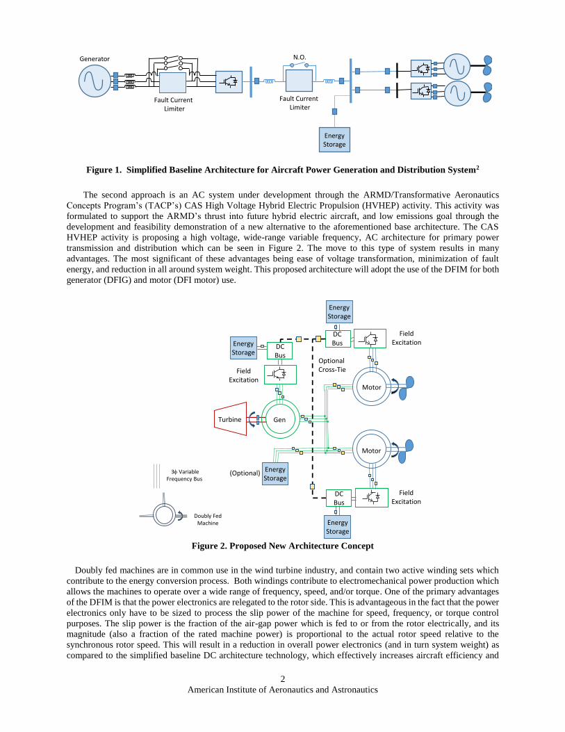
The second approach is an AC system under development through the ARMD/Transformative Aeronautics
Concepts Program’s (TACP’s) CAS High Voltage Hybrid Electric Propulsion (HVHEP) activity. This activity was
formulated to support the ARMD’s thrust into future hybrid electric aircraft, and low emissions goal through the
development and feasibility demonstration of a new alternative to the aforementioned base architecture. The CAS
HVHEP activity is proposing a high voltage, wide-range variable frequency, AC architecture for primary power
transmission and distribution which can be seen in Figure 2. The move to this type of system results in many
advantages. The most significant of these advantages being ease of voltage transformation, minimization of fault
energy, and reduction in all around system weight. This proposed architecture will adopt the use of the DFIM for both
generator (DFIG) and motor (DFI motor) use.
Doubly fed machines are in common use in the wind turbine industry, and contain two active winding sets which
contribute to the energy conversion process. Both windings contribute to electromechanical power production which
allows the machines to operate over a wide range of frequency, speed, and/or torque. One of the primary advantages
of the DFIM is that the power electronics are relegated to the rotor side. This is advantageous in the fact that the power
electronics only have to be sized to process the slip power of the machine for speed, frequency, or torque control
purposes. The slip power is the fraction of the air-gap power which is fed to or from the rotor electrically, and its
magnitude (also a fraction of the rated machine power) is proportional to the actual rotor speed relative to the
synchronous rotor speed. This will result in a reduction in overall power electronics (and in turn system weight) as
compared to the simplified baseline DC architecture technology, which effectively increases aircraft efficiency and
Figure 2. Proposed New Architecture Concept
FieldExcitation
Optional Cross-Tie
Gen
Motor
FieldExcitation
FieldExcitation
Motor
Turbine
Doubly Fed Machine
3f VariableFrequency Bus
(Optional)
DCBusDC
Bus
DCBus
Energy Storage
Energy Storage
Energy Storage
Energy Storage
Figure 1. Simplified Baseline Architecture for Aircraft Power Generation and Distribution System2
Fault CurrentLimiter
N.O.Generator
Fault CurrentLimiter
Energy Storage

3
American Institute of Aeronautics and Astronautics
reduces CO2 emissions. This paper will describe this DFIM based AC power system, its control, potential benefits,
challenges, and current development efforts to determine the validity of said system.
II. Power System Architecture and Basic Principles
Figure 2 is the conceptual power architecture for a potential DFIM based hybrid electric power system. The overall
system consists of a DFIG, a primary AC transmission and distribution bus, several DFI motors to drive the propulsors,
a DC bus which provides field excitation through an inverter, energy storage on the AC and DC buses, and breakers
for protection.
A. Generator
The DFIG operates as a stand-alone generator acting as a voltage source, providing variable voltage, variable
frequency power to the network. The capability to control output voltage and frequency allows the generator to
essentially act as a variable speed drive to all downstream motor loads. As a variable speed drive, the DFIG can
increase or decrease its output voltage and frequency proportional to one another to obtain higher or lower output
power production respectively. In addition, the propulsor motors can be soft started, completely eliminating the need
for full voltage starting for propulsor motors.
The control of the stator frequency is accomplished through field control by the inverter. When the inverter controls
the rotor field such that it rotates in the same direction as the DFIG rotor, a super-synchronous bus frequency (high
power operation) will result according to Eq. 1, where fstator is the stator frequency, nrotor is the shaft speed in revolutions
per minute (rpm), p is the number of poles of the machine, and frotor is the electrical rotor frequency.
𝑓𝑠𝑡𝑎𝑡𝑜𝑟 =𝑛𝑟𝑜𝑡𝑜𝑟 ∗ 𝑝
120+ 𝑓𝑟𝑜𝑡𝑜𝑟 (1)
Conversely, a rotating magnetic field controlled to rotate counter to the rotational direction of the DFIG rotor will
create a sub-synchronous bus frequency (low power operation) according to Eq. 2.
𝑓𝑠𝑡𝑎𝑡𝑜𝑟 =𝑛𝑟𝑜𝑡𝑜𝑟 ∗ 𝑝
120− 𝑓𝑟𝑜𝑡𝑜𝑟 (2)
In both super- and sub-synchronous operating modes, the stator voltage is controlled by directly increasing or
decreasing the field excitation voltage.
In terms of operating modes during the major stages of the flight profile, super-synchronous operation will be used
in the takeoff and climb portions, along with maneuvering where higher output power is required for the aircraft. Sub-
synchronous operation on the other hand would be used during idling or descent where less power is required by the
propulsor motors. Operation during cruise will most likely occur around the synchronous operating point.
B. AC Transmission and Distribution Bus
The voltage and frequency of the AC network are expected to be in the range of several kilovolts (kV) and kilohertz
(kHz) respectively. This allows for the distinct advantage of minimizing any possible magnetics, cabling, and
switchgear on the transmission and distribution network, providing lower overall system weight. The high frequency
AC transmission and distribution concept has been demonstrated and verified in past works at the 20 kHz level at the
NASA Glenn Research Center (GRC), including the development of low reactance cables for such a system3. It is
important to note that no power processing exists on the AC bus; all power is directly transmitted from the generator
to the motors. The electromagnetic interference (EMI) implications of this high frequency AC bus is a recognized
concern however, and requires further study to identify the potential problems and possible solutions.
C. DFI Motor
The DFI motors operate under differential speed control to drive the propulsors and control thrust. In a manner
similar to the DFIG and its output voltage and frequency, the DFI motors can control shaft speed sub- or super-
synchronously relative to the stator frequency, independent of one another. This is performed via field control;
excitation of the rotor via a three phase inverter tied to a DC bus allows control of the power flow to and from the
rotor. Power injected into the rotor allows for super-synchronous operation of the DFI motor shaft, and power absorbed
from the rotor allows for sub-synchronous operation. Field control of the DFI motor may also possibly allow several
other unique advantages. One additional advantage is that through field control, any overhauling loads (loads pulling
faster than the excited speed) that occur due to a drop in system frequency may have the ability to regenerate energy

4
American Institute of Aeronautics and Astronautics
back through the rotor, not the stator, through ramped sub-synchronous operation. Secondly, if a DFI motor were to
ever be isolated from the primary AC bus via the AC breakers opening, resynchronization to the AC bus can be
accomplished by using field control to align the stator voltage with the grid voltage in phase, magnitude, and
frequency, and then closing the AC breakers. The field could then be subsequently realigned to maximize the torque
produced in the machine.
D. DC Bus
The DC bus, or DC buses in the case of a distributed architecture, plays a critical role in the proposed doubly-fed
system. This bus is of the utmost importance, since the rotor power of each individual DFIM must be supplied to, or
received from the DC bus itself through the respective DFIM inverters. To maintain stability throughout the system,
the DC bus is expected to be regulated. Regulation will be accomplished through the use of energy storage elements
and integral shunt regulators, which will maintain the voltage magnitude of the bus at the necessary set point and
increase stability of the system.
A major benefit of the proposed system topology is that it offers multiple options for configuration of the DC bus
or busses. This includes a common DC bus architecture, or distributed DC bus architecture. A common DC bus
architecture would utilize cross-tying of distributed DC buses across the aircraft, and could occur solely on the motor
side, or include the generator as well. If the DC bus associated with the DFIG was to be tied with the DC bus of the
DFI motors however, the machines would be required to have equivalent stator-to-rotor turns ratios. On the other
hand, a distributed DC architecture could be implemented, where each DFIM has its own respective DC bus. A
distributed architecture would promote redundancy and increase reliability, while a common DC bus architecture
would promote regenerative power flow to and from machines (at certain operating points) and the reduction of energy
storage components.
E. Load Leveling and Reactive Power Compensation
The power and stability requirements of the aircraft power system over the flight profile may require additional
power capability beyond that which the turbine was originally designed to provide. Peak demands during takeoff and
maneuvers, and loss of load during descent can be partially supplied through the use of energy storage devices as load
levelers. These energy storage devices can be incorporated on the DC bus via a variety of technologies such as
capacitors, batteries and/or fuel cells interfaced through a bidirectional converter, and possibly the AC bus via an
additional DFIM coupled to a flywheel4. The amount of energy storage and the storage medium have not been
determined at this point in time, but it is important to note that all types of energy storage can easily be integrated into
the system architecture.
F. Protection
The proposed system will be inherently reliable through a combination of AC and DC side protection via breakers,
and also inverter field control. Similar to a common strategy used within terrestrial protection systems, the overall
protection strategy for the doubly-fed system will analyze and clear faults based on a zone-based protection scheme.
Simply, the system will be divided up into a number of protection zones, and it is the primary responsibility of the
switchgear within the zone of the fault to clear said fault. One example is a fault on the AC bus. A bus differential
relay would be responsible for clearing the fault by opening up all the breakers associated with the bus zone. Another
example is a fault on the stator or rotor feeder conductors of a DFI motor. In this case, both the DC bus and the AC
bus would contribute energy to the fault. Therefore, both the AC and DC buses would need to be isolated from the
fault through breakers on each bus. During the fault, the DFI motor inverter is also expected to ramp down field
excitation and disable operation. If the fault is cleared, the stator side breaker will remain open, and the DFI will
resynchronize with the primary AC bus voltage, frequency, and phase, and slowly resume operation. One problem
that must be addressed for the entire protection system, however, is that all faults must be cleared at high speed within
the high frequency network so as to maintain system stability5.
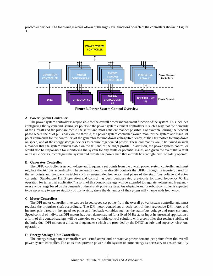
III. Power System Control
In order for the proposed power system to effectively meet the demands of the pilot, and ensure safe and efficient
operation of the aircraft, the power system must include both elemental and system-wide control. The control structure
that meets such objectives is shown in Figure 3. In this structure, an overall power system controller monitors,
configures, and issues set points to the individual power element controllers. The power element controllers directly
control their respective individual power elements such as the DFIG, DFI motor, energy storage devices, and
5
American Institute of Aeronautics and Astronautics
protective devices. The following is a breakdown of the high-level functions of each of the controllers shown in Figure
3.
A. Power System Controller
The power system controller is responsible for the overall power management function of the system. This includes
configuring the system and issuing set points to the power system element controllers in such a way that the demands
of the aircraft and the pilot are met in the safest and most efficient manner possible. For example, during the descent
phase where the pilot pulls back on the throttle, the power system controller would monitor the system and issue set
point commands for the controllers of the generator to ramp down voltage/frequency, of the DFI motors to ramp down
on speed, and of the energy storage devices to capture regenerated power. These commands would be issued in such
a manner that the system remain stable on the tail end of the flight profile. In addition, the power system controller
would also be responsible for monitoring the system for any faults or potential issues, and given the event that a fault
or an issue occurs, reconfigure the system and reroute the power such that aircraft has enough thrust to safely operate.
B. Generator Controller
The DFIG controller is issued voltage and frequency set points from the overall power system controller and must
regulate the AC bus accordingly. The generator controller directly controls the DFIG through its inverter, based on
the set points and feedback variables such as magnitude, frequency, and phase of the stator/bus voltage and rotor
currents. Stand-alone DFIG operation and control has been demonstrated previously for fixed frequency 60 Hz
operation for terrestrial application6; a form of this control strategy will be extended to regulate voltage and frequency
over a wide range based on the demands of the aircraft power system. An adaptable and/or robust controller is expected
to be necessary to ensure stability of this system, since the dynamics of the system will change with frequency.
C. Motor Controllers
The DFI motor controller inverters are issued speed set points from the overall power system controller and must
regulate the propulsor shaft accordingly. The DFI motor controllers directly control their respective DFI motor and
inverter pair based on the speed set point and feedback variables such as the stator/bus voltage and rotor currents.
Speed control of individual DFI motors has been demonstrated for a fixed 60 Hz stator input in terrestrial application7;
a form of this control strategy will be extended to a variable control solution, with a controller that retains stability of
the individual DFI motors at all stator frequencies (which are provided by the DFIG) at sub- and super-synchronous
operation.
D. Energy Storage Unit Controllers
The energy storage units controllers are issued active and or reactive power demand set points from the overall
power system controller. The units must provide power to the system or store energy as necessary to ensure stability
Figure 3. Power System Control Overview
POWER SYSTEM CONTROLLER
GENERATOR CONTROLLER
MOTOR CONTROLLER #1
ENERGY STORAGE
CONTROLLER #1
PROTECTIVE RELAY #1
DFIG
DFI MOTOR #1STORAGE UNIT
#1BREAKER UNIT
#1
MOTOR CONTROLLER #1
DFI MOTOR #1
MOTOR CONTROLLER #1
DFI MOTOR #1
ENERGY STORAGE
CONTROLLER #1
STORAGE UNIT #1
ENERGY STORAGE
CONTROLLER #1
ENERGY STORAGE UNIT
#1
PROTECTIVE RELAY #1
BREAKER UNIT #1
PROTECTIVE RELAY #1
BREAKER UNIT #1
Power Element Controllers
Power Elements

6
American Institute of Aeronautics and Astronautics
of the system. The units must also be monitored such that the total energy stored does not exceed or fall short of any
predetermined threshold.
E. Protective Device Relays
Local high speed protective relaying will be associated with each breaker on the AC or DC bus to issue trip
commands, similar to a utility system. The relays will communicate status updates with the overall power system
controller, and can be commanded by the power system controller to open or close their respective breakers as well
for power system configuration management.
IV. Preliminary DFIM System Development and Verification
To develop, evaluate, and verify the operation of the proposed DFIM system, it is necessary to run the control
against a representative power system; however, the cost and time necessary to perform these tasks on a high voltage
and high frequency system are not attractive to NASA. The basic functionality of the system is being demonstrated
using commercial off-the-shelf (COTS) low power hardware and simulation of such hardware to determine feasibility
of the approach, and will be scaled to the megawatt (MW) level as the concepts are proven out. The existing low
power test bed (LPTB) diagram and hardware is shown in Figures 4 and 5 respectively. The system currently consists
of four 250 watt (W) permanent magnet DC (PMDC) machine and wound rotor induction machine (WRIM) pairs (the
WRIM is a DFIM in this system), with the machines and AC bus configured in the same manner as the system shown
in Figure 2. One pair simulates the DC machine as a turbine and the WRIM as a DFIG generator, while the other three
pairs simulate the WRIM as a DFI motor and the DC machine as a fan load via dynamometer action. Each DFIM is
fed via a three-phase inverter which ties to a nominal 42V bus coupled to a regulated bidirectional DC supply. The
LPTB uses the distributed DC architecture, where each machine has its own respective bidirectional DC bus (no cross
tie). The test bed contains all of the necessary instrumentation for monitoring, control, and protection of the hardware,
with all of the aforementioned functions being provided by a high-speed data acquisition and control system.
Figure 4. Low Power Test Bed Schematic

7
American Institute of Aeronautics and Astronautics
The LPTB machines have completed preliminary testing and evaluation, with the analytical models of the
machines being developed using Simscape Power SystemsTM. The state-averaged model of the inverter based on the
data sheet characteristics has also been developed within Simscape Power SystemsTM. A comparison of the simulation
and hardware results are shown in Figures 6 and 7 for the WRIM with shorted rotor coupled to the DC Machine.
Figure 6 shows the applied stator voltage of 15 volts root mean square (RMS) line-to-line at 60 Hz to the DFIM, and
Figure 7 shows the resulting stator current. Rotor current simulation results were also found to be within 10 percent
of the hardware values. Test results have shown good correlation between the software models and the hardware.
However, the results have also demonstrated the inefficiencies of the fractional horsepower machines, especially the
DFIG. These losses include relatively high leakage resistances due to small conductor sizes, and relatively high
frictional losses compared to the rating of the machine. A 750W alternative generator is currently being developed to
overcome these inefficiencies and provide increased power system capacity to the existing motors.
Figure 5. Low Power Test Bed Hardware
Figure 6. Applied Stator Line to Line Voltage AB to WRIM coupled to PMDC Machine, Hardware versus
Simulation

8
American Institute of Aeronautics and Astronautics
With accurate hardware models, the basic control and stability of the system will first be demonstrated in software.
This consists of demonstrating the power element control layer containing the regulator loops for the DFIG and DFI
motor, then integrating the power control elements together and adjusting the top level control system to guarantee
stability of operation. Once the total control of the system and its elements are realized within the software
environment, the controls will be directly applied to the test bed hardware using rapid prototyping technology. This
provides development and evaluation in a timely and cost effective manner, with minimal risk to hardware.
A preliminary PI-based DFIG controller has recently been developed by NASA GRC to demonstrate closed-loop
voltage and frequency control of the generator. This controller is based on the control techniques described for a stand-
alone terrestrial DFIG in Ref. 6, and is interfaced with the stand-alone DFIG system shown in Figure 8. The generator
contains the same characteristics as the 250W machine described previously, has a constant shaft speed of 1800 rpm
and has its stator feeding a fixed wye-connected load with 5 Ohms and 10uF per phase. Variable frequency and voltage
operation is demonstrated in Simscape Power SystemsTM as shown in Figure 9, which shows the primary bus voltage
and frequency shift from sub-synchronous operation at 12.75 volts RMS line-to-line and 51 Hz respectively, to super-
synchronous operation at 17.5 volts RMS line-to-line and 69 Hz respectively.
Figure 7. Stator Currents of WRIM coupled to PMDC Machine, Hardware versus Simulation
Figure 8. Stand-Alone DFIG System Implemented in Simulation
3f Line to Neutral Voltage Sense
DFIG 3 Phase AC Load
Controller
42 VDC
Rotor Current Sense

9
American Institute of Aeronautics and Astronautics
Robustness and stability of the overall control strategy will be evaluated in the future with respect to various
operating voltages and frequencies on the bus with dynamic loads. In addition to the DFIG control, a variation of the
speed control algorithm of the DFI motor demonstrated in Ref. 7 is being evaluated, along with the possible inclusion
of a DFIM based AC energy storage system.
V. Summary and Future Work
Hybrid electric vehicles may enable development of ultra-efficient commercial vehicles and the transition to low-
carbon emission propulsion, which are critical thrust paths within NASA. NASA GRC has proposed a primarily AC
based power system architecture which reduces cable, power electronics, and switchgear weight through the use of
high voltage, high frequency, doubly-fed machines. Prior work based on 60 Hz operation of the DFIG and DFI motor
has been demonstrated in academia, and these concepts will be expanded to variable operation. The challenges of
implementing and integrating such a system are currently being investigated through the use of a low power test bed.
If stable operation of the proposed system is verified, NASA GRC plans to expand demonstration on a high power
test bed, possibly in the MW range.
Acknowledgments
The authors would like to thank the NASA CAS project for the support of this effort, Benji Loop and Ning Wu of
PC Krause and Associates who assisted with the simulation results, and Casey Theman, Keith Hunker, Tom Balogas,
David Hausser, and George Horning of the CAS HVHEP activity for their assistance in the construction of the low
power test bed.
References 1Gemin, P., et al., RTAPS “Architecture, voltage and components for a turboelectric distributed propulsion electric grid (AVC-
TeDP),” NASA CR-2015-218713, 2015.
2Armstrong, M.J., et al., RTAPS “Architecture, Voltage, and Components for a Turboelectric Distributed Propulsion Electric
Grid,” NASA CR-2015-218440, 2015.
3Hansen, I. G., and Wolff, F. J., “20 kHz Space Station power system,” NASA TM-88801, 1986.
4Ferreira, A. C., Souza, L. M., and Watanabe, E. H., "Improving power quality with a variable speed synchronous
condenser," Power Electronics, Machines and Drives, 2002. International Conference on (Conf. Publ. No. 487), 2002, pp. 456-
461
5Zheng, H., “High Frequency AC Power Systems,” Ph.D. Dissertation, Electrical Engineering Dept., University of South
Carolina, Columbia, S.C., 2014.
Figure 9: Simulation Demonstration of Variable Stator Voltage and Frequency

10
American Institute of Aeronautics and Astronautics
6Iwanski, G., and Koczara, W., “Sensorless direct voltage control method for stand-alone slip-ring induction generator,” Power
Electronics and Applications, 2005 European Conference on, Dresden, 2005, pp. 10 pp.-P.10.
7Yuan, X., Chai, J., and Li, Y., “A Converter-Based Starting Method and Speed Control of Doubly Fed Induction Machine
With Centrifugal Loads,” IEEE Transactions on Industry Applications, vol. 47, no. 3, pp. 1409-1418, May-June 2011.