proposal an integrated mmw radar - robotics institute · however. they have the following...
TRANSCRIPT

Proposal for an Integrated MMW Radar System for Outdoor Navigation
Dirk Langer
CMU-FU-TR-96-15
The Robotics Institute Carnegie Mellon University
5000 Forbes Avenue Pittsburgh, PA 15213
10 March 1996
631996 Camegie Mellon University
This research is supported by TACOM in contract DAAE07-9O-C-RO59, ' CMU Autonomous Ground Vehi- cle' and US DOTin agreement DTFH6I-94-X-00001, 'Automated Highway System'.
The views and conclusions expressed in this document are those of the author and should not be interpreted as represe.nting the official policies, either express or implied, of the US government.


Abstract
[Notr: This technical report is mostly my unchanged thesis document. excepr for .secti<in 2.1. iiii updated section 7 and appendix B.]
The design of a MMW radar sensor for mobile robot outdoor navigation is pi-crented. that is xhle to operate robustly even under adverse weather conditions. This sensor has a range of apl1r1>xii mately 200 metres and uses alinear array of receivers and wavefront reconstruction techniques to compute range and bearing of objects within the field of view. Currently. sensor desipn and harcl- ware fabrication have been completed and the sensor is being integrated with other vrhicle by.;-
tems. Signal processing techniques are discussed and results obtained from simulation and the real sensor are presented.
Clutter rejection and the ability to classify and differentiate between objects will be improved in addition by integration of the radar data with information from a road geoinetry perception sys- tem. Road geometry perception will he based either on lane marker detection throuph ii video camera or a digital road map.
The integrated sensor system can operate as a copilot for a human driver for speed control w i t h respect to traffic density and as a safety monitor for lane changing. In addition i t will be ahle to interact with other modules such as road followers and higher level planners for complete autrin- omous driving.
i


Table of Contents
1
1.1
1.2
1.3
2
2.1
2.2
2.3
2.4
2.5
3
3.1
3.2
3.3
4
5
6
7
Introduction ...................................................................................................... I
Sensor Systems Overview .................... ..................... ..................
Ganesha Overview ............................................................ Previous work .....................................................
Sensor Design Concept ..................................................................................... 3
Radar Specifications ............................... 4 Data Processing ....................................................................... Preliminary Results ...............
Local Target Grid Map ................. ........................ 8
Integration with Road Geometry System ....................................................... f 0
Problem Situations ...................... 10
Map based Solution .....................
Geometry.. ..................................................................................................... .......................................................
, , . . , , . . , , , , , . , , . . , , , , . , ,
, , , , , . . , , , , , , , , , , . , , , , , . . , , , , , , , , , , , , . , , , , , , , , . . , , , , . ....................... x .......... ........................
. , , , , , . . , , . , , , , , . , . . , , , , , , , ...................................................... ......................................................................
Vision based Solution .................................
Vehicle Velocity Control ................................................................................. 12
Research Agenda ............................................................................................ 13
Contributions .................................................................................................. I 3
Schedule .......................................................................................................... 14
References ...................................................................................................... I 4
Appendix A (Radar Block Diagram) ............................................................ I 5
Appendix B (Technical Specifications) ....................................................... 16
Appendix C (Sensor Geometry) ................................................................... 17
Table of Contents


List of Figures
Figurc 1 Sensor Geometry .................................................................................................. Figure 2 Area coverage in horizontal .................................................................................. 3 Figurc 3 Radar Simulation of target Figure 4 Resolution limit of Fourie sform ....................... ...........................
............................................................................ 6
Figure 5 Power Spectral Density for 32 complex data points ........................................... 7 Figure 6 Radar Data obtained on Highway ........................................ Figure 7 Local Grid Map ....................................................................... Figure 8 Traffic situations leading to potential false alarms ..................
Figure 10 Typical road scene with extracted lane geometry ........................................... 12 Figure 11 Steering Arc Evaluation ................................................................................... 12
FMCW Radar Block Diagram (Appendix A) .................................................. 15 ... 17
........................ 18 Geometric Analysis of different traffic scenarios (Appendix C) ..................... 18
Figure 9 Digital Map of Urban Area (in Pittsburgh) ............................
................................................ Minimum Turn Radius (Appendix C) Maximum road gradient (Appendix C) ...............................
List of Figures ... 111


1 Introduction
Collision Avoidance and the detection of objects in the envilonment is an important task fbr on ;~ulononious mohilc vehicle. So far, robots have mostly used sonar and shon range laser based sensors. The GANESHA sy<teril lh:is dcmonstrated the use of these sensors to accomplish these nouigationnl tasks at low speeds. HOII~VCI-. the ~~~rce]it i i , i i capabilities of GANESHA are inadequate for autonomuus driving at higher specds. both on ro;id and cros<-cuimTr?. Some perception systems have been developed, based on laser. radar or CCD cameras. 10 provide it lonfer r.iilgc sensing capability and detect obstacles. However. to date none of these systcms has demonstrated the :ihility I r !
operae robustly under all weather conditions and return all the necessary geometric information ahoirt ~~oteiiliiil collision targets and safe driving directions. Pmhlems especially still persist i n cluttered environments. such tis
country or city roads with oncoming traffic. My thesis research therefore proposes the following:
1.
2.
To build a robust. all weather, long range sensor with crude imaging capabilities.
To integrate the sensor with geometric road information and vehicle state [turn arc and wlucity) l o r tit1
imprn\,ed driving system.
I will demonstrate new capabilities with the GANESHA navigation system, through the development (I( i i s u ( w i r i r perception system and using the CMU Navlab vehicles. These capabilities will include the deteutirrn ,IF ~ i n r ~ ~ i i d ubstacles including people under all weather conditions, safety monitor for lane changing and s p e d uii l irol u:illi respect to traffic density.
1.1 Sensor Systems Overview
In the context of a mbot automobile driving at moderate or high speeds. a sensor with a fairly lrrnf range i.s needed. The proposed sensor system is designed such that it could operate in environments with the frrllmving geomety:
Multilane roads with other vehicles such as lorries, ears. motorcycles. Pedestrians are aswriicd t u lx present only i n an environment where vehicles move relatively slow.
Therefore the sensor should fulfill the following requirements:
- - *
* - - *
*
Maximuin mnge between 100 and 300 metres
Can operate under adverse weather conditions (rain, snow).
Can operate at night and when visibility is poor (fog).
Data rate should be about 10 Hz. Longitudinal resolution between 0. I and I m
Lateral resnlution must be able to discriminate between vehicles in different lanes for Highway sccnari(r
Preferably no mechanically moving parts
Safe operation in environments where humans are present.
No interference between different sensors.
Keeping the above requirements in mind, it was decided to choose a radar based sensor system. There iire iilso other potential candidates available for the sensor requirements described which are based on different physical principlcs. However. they have the following disadvantages for the application as compared toil radar hased system:
Stereo or other video camera vision based methods do not work well at night in general ns they depend 011 iiii
external source for illumination. Owing to lhe structure of il CCD. they have good lateral resvlutioii. hut ii ;ood longitudinal resolution can only be achieved at relatively high computational costs. The hotprint of ii pixel and \ izc of the CCD are among the factors that determine maximum range and accuracy. I n order to get good rrsalution :it
long ranges. the baseline needs to be wide which is limilei by the. width of the vehicle and the required oi,erl;lp

Proposal for an Integrated MMW Radar System for Outdoor Navigation: March 1996
between the stereo images, Another problem in stereo is the need to mount the stereo rig ripidly iin the vchiclc 10 avoid calibration errors. The wider the baseline. the more problematic is a rigid mount. I n teriiis of size. ciirretit \Icrcii sensors nlsu require a relatively large volurnc in space fot- mounting and computing.
Laser sensors are also light based sensors. Since they emit laser light actively, they illso work at iniftit. Cr i i i i lwcd Io a radar sensor. they are able to resolve smaller objects due tu the smaller wavelength. Howrver. they suffix 1roii1 errors due to reflection problems from dark surfaces or mirror like and transparent sui+aces. Laser hsmir :ils(i ha\ much sharper drop off at the 3 dB beam angle width which leads to a much narrmver effective beiim w i~ l t l i . A l ~ w r sensor might therefore miss a target in the vehicle's own lane at long ranges.
Both. stereo and laser based sensors have problems working under adverse weather conditions csprci:illy wlici i visibility i s reduced since they both work ot visible or near visible light wavelengths. A radar sensor exhibits much better characteristics under these conditions.
1.2 GANESHA Overview
I n order to further process the sensor rangedata and make it available for higher level interpretation modules. i l ic d i i l :~ needs to be position tagged and stored in a map. GANESHA (Grid based Approach,fiv Nui~ignfi~iri h v l?i.klcii<c
Storage und Histogram Analysis) i s a system using sonar or the E R I M laser range camera that we iinpleinentcrl lirr the autonomous land vehicle Navlab. The system builds a local grid map of its cnvironment from the sensor diit i i . Thc map raw data i s filtered in several steps. The information collected in the map can then be used for ii variety o i applications in vehicle navigation l i t e collision avoidance, feature tracking and parking. An algi)rithm WI,\
implemented that can track a static feature such as a rail, wall or an array of parked cars and use this infkm;itiriii 111
drive the vehicle. In tracking mode, steering commands are generated using the pure pursuit method. I n uhstikclc avoidance mode a set o f turn arcs i s evaluated for potential collisions with obstacles. Steering cnininiinds generated by selecting a permitted turn arc in the desired direction.
park the vehicle [XI . It has also shown its ability to aid in navigation through a cross-country environment 171 GANESHA has demonstrated i ts ability to autonomously drive a vehicle, search for a parking gap and pnr:kllcl
1.3 Previous work
I n the last LO years several sensor systems have been developed for collision avoidance in automobilm tisiiig different approaches. Mercedes-Ben2 and DickmanndGraefe e t a1 equipped their vehicles with video cimiel:is iw road following and obstacle sensing. Other automobiles and their range are detected from a single video iiiiiige usins a car model and relative s i x o f the object in the image. Recently their test vehicle was equipped with I 8 video cameras looking in al l directions. This way also objects on the side and coining up from behind are sensed.
Leica has developed an infrared laser range system. The multibeatn version (MSAR Odin) uses fivc hs;uns :IIK
covers a total Horizontal Field of View (HFoV) of 7.5" with a max. range of IS0 in. Mercedes-Benz equippucl m e o1 the Pmmerheirs vehicles with this sensor and integrated i t into an intelligent cruise control. When trJveling rhnlugli ii bend, the system uses steering angle information to focus on objects detected by the outermost sensor beimir iiiid filter stationary objects.
A simplified single beam version (Odin 11) has a HFoV of 3 O with an operating range of 20 to 80 in. Distancc accuracy i s about 3 m.
Several automotive and electronics companies have developed radar based systems for intelligent cruise c<introl and collision avoidance applications (Mercedes-Benz. Vorad, Millitech. TRW. Delco. Toyota. GEC Plescey. Phi I l i p . etc.). Most of these systems use a single narrow beam sensor to detect other vehicles in the vehicles own di-iring lanc. Millitech developed a pulsed three beam system with a total HFov o f 6'. The outer beams are used io clistinguish between a strong target in an adjacent lane and a weak target in the vehicle's own lane. The Vor;k r;id;ir uses t l ic doppler range method This means that a range measurement can only be obtained when there is relative n ~ o ~ e m r n t between sensor and target. All of these sensors potentially have problems locating a target properly in curve\.
At the Technical University Munich (TUM), an automotive radar with ii 12" HFoV and an opcratiiif r:ingc 0 1 3 1 io Io0 m has been de\'elnped [ IO ] . Range is obtained through binary phase coding with pseudo r;mrlrrm noise ;, t~d :I
range resolution o f 0.75 m. This radar also returns directiunal information through wave front reconstruction \+,ill>
2

Proposal for an Integrated MMW Radar System for Outdoor Navigation: March 1996
multiple receivers
2 Sensor Design Concept
This design is closely related to that of the TUM radar, as it appeared that this type of design would offer ille hehi compromise in terms of capabilities and technological simplicity. However, our design includes soinc sisnilicani changes.
2.1 Geometry
c .. . . . . . . . . . 200m
-
Figure 1 Sensor Geometry
The geometry of the proposed radar sensor is shown i n Figure 1 . A vertical field of view of 3' was chosen AS it provides the best compromise between good obstacle coverage in the vertical direction and avoiding Mse measurements due to ground reflections and returns from road signs or other structures located overhead. At l o n ~ e r ranges the ground (road) will reflect specularly. The current design shows a horizontal field of view of 12'. which is divided into four or more angular resolution cells. Assuming an average highway lane width of 4 metres, the sensot- will provide an area coverage in the horizontal plane as shown in Figure 2. One lane will be covered at n range of approximately I 9 metres, three lanes will be covered at a range of 57 metres and five lanes at a range of 95 tnletres. ;\ 3" angular resolution cell covers an entire lane width at a range of 76 metres.
It would have been preferable to use a larger horizontal field of view of up to 20'. However, for cost reilsons i n fhr mtenna design we settled on the HFoV shown.
3

Proposal for an Integrated MMW Radar System for Outdoor Navigation: March I996
......................................................................................
.....................................................
20 in .............
......................................................................
9-7 1'cell 95
Figure 2 Area coverage in horizontal
In order to stop for a stationary object at highway speeds of 100 kmh (- 65 mph) a detection distance o l a t l e a s 55 metres would be needed (assuming a = -1 m / s and negkcting reaction time). Since in autonomous mode. ihc vehicle needs to reacl to objects moving at considerably different relative speeds, the maximum rangc of the scns;lr for detecting vehicles is designed to be about 200 metres. People have a much lower radar cross section (0.1 - 2 in- i as cumpared to vehicles (IO m 1 and can therefore be detected only at a much smaller maximuin range. For the proposed sensor system. this would be about M) metres. However, this does not pose a problem as people are assumed only to be present in a road environment where vehicles also move considerably slower. i.e. 50 kmlh (-30 mph).
2
L
2.2 Radar Specifications
For simplicity of design and better sensitivity, it was decided to operate the radar as a Frequency ~11~du1;itecl Continous Wave (FMCW) system. A block diagram of the design is shown in Appendix A. The carrier frequency is at 77 GHz. The corresponding wavelength will be in the mm-Range which results in better resolution of scene tletiiilC
than at lower frequencies. Also, above 30 GHz. reflection from vegetation and foliage is more significant. Attcnuatinri at these frequencies is larger than at lower ones. However, this also keeps the maximum ranze of the r x h r r r la l iuc ly short and thus reduces interference. A carrier frequency in the millimeter wave range also allows larser I'rcqusncq. sweeps for better range resolution and limits interference with existing commercial radio frequency trilnhmittei-s. Because the transmitted signal is spread over a large bandwidth, an FMCW radar is quite robust against intcrfersncc from other sensors of the same type. Interference can be further reduced by using a coded FM wave form Fw :I simple radar system the maximum range resolution is related to the bandwidth by the following relation:
C ( I 1
The frequency sweep ZAf of the radar is 300 MHr, which therefore results i n a range resolution of 0.5 111. l w ;I
maximum range of R = 200 m and a desired maximum intermediate frequency (IF) of f fF = 500 kHz. the modulation frequency f,n is given by equation (2) and is calculated to be 625 Hz for a triangular modulati(~n :ind
1.25 kHz for a sawloah modulation:
6R = 2B - B = 2Af
r,, = "" (Bipolar Triangle) Jn = wR ' f 'F (Sawtooth)
If the FM waveform used is triangular, maximum unambigious range is 1200 k m and can he calculntrd lroin equation (3):

Proposal for an Integrated MMW Radar System for Outdoor Navigation: March IO96
In order to he able to detect vehicles and people within the given range, transmitter power of the rxliir s ? s ~ c r n i i i l l
Range and angula information of targets are obtained by Fast Fourier Transform [FFT) or sirnilill- cpecn;nl ;in:ilysis he around 30 mW, as can be calculated from the radar equation (see 141, 131).
methods as described in the following section.
2.3 Data Processing
The output of the mixers on the receiver channels of the radar sensor (see Appendix A) is ;I mixture r+rliftvrc.nt frequencies. Each discrete frequency corresponds to range to a target. Therefore the range t u a target can be ohtiiiiicrl efhciently by using a FFT. The received signals are first passed through a high pass filter which acts ins ii i-;in;t.
dependent gain. since signal frequency corresponds to range. The signals are then ainplitied and fed tlirwph i t Iwv p a s filter at SO0 kHz before being convened to digital. The low pass filter prevents errors due to aliasing dfecih i n the succeeding FFTs.
Angular bearing and range to the target is obtained by digital wave front reconstruction and heam forinnins. This involves two consecutive FI;Ts along the time and space dimension of the signal. The space dimension is i n this c:isc the four receiver elements that are used to sample the incoming wave front at discrete points in space. Thc hist I.FT along the time dimension of the receiver output signal gives target range as mentioned above. The accond FFT iilcm: the space dimension performs a cross correlation that is a measure of the time lag hetwee.n the signals in c i d l rcccivcr channel. The maximum peak in thecorrelation indicates the time lag and thus the hearing of the incoining sipniil, A more detailed description of the method is given in [2] and [ 5 ] . Since the radar currently has four ttceivers. we nhtiiin four angularresolution cells as shown in Figure I . In order to determine target hearing unambigously within the givcn sensor's field of vie.w, the following condition for the receiver antenna spacings Ax, needs to be obeyed:
Axi < ' . h sin (2n,) (4)
where 2a
Figure 3 : (a) shows the overlaid time signal from the output of two of the four mixers. Note that the range inI~~~iin:itio~i iz contained in the frequency and the bearing information in the phase shift of the signds. (h) is the spectrum of the fourier transformed time signals for 1024 data points. The four spectra from thc inixrrr iirc overlaid. The noise level at -350 [dB] is just numerical noise in channel 0. The noise level i n channels 1-3 i s I I I U C ~
higher due to leakage effects in the FFT. In this simulation. we did not introduce any system noise but just urcd idriil signals. (c) shou~s a contour plot of the range YS. hearing matrix after the second FFT is applied along the spiitinl ditncnsio~n. In the range dimension we used 256 data points. In the hearing dimension we used 64 bins. Since there arc only lour data points from the four receivers, the remaining bins are zero padded. The peaks indicating tarFets A and U ciin hc seen at their expected locations. (d) is a cross-sectional cut through the range vs. bearing matrix at the calculated range for target A and tarset U. Thc difference in level between the main lobe and the first side lobe is I I .5 [dB1 as predicted by theory I I]. ( e ) shows a mesh plot of the same range vs. bearing matrix as in (c).
- 1 2 O is the unamhigous range, i.e. the horizontal field of view. E -. The radar signal processing is shown in simulation for simulated targets at (50 m. 2") and (15Oin. -5'' ) i i i
The simulation was implemented using the MATLAB software package.
The Fourier Transform is limited i n resolution by the number of data points given. This mciins for the hearins dimension that one resolution cell is 12" 14 = 3": since we have four receivers in the spatial dimenairin. Iie~nce i f two targets are at the same range, but their hearing is less than 3" a p t . thcy cannot be rrsolved m y t n ~ ~ [ - c :rind ;i~-c
merged into one target lohe. This situation is illustrated in Figure 4: In (a). the tzrgets are 3" apart and can just be resolved; In (h) the targets are less than 3" apart and cnnnnt bc t-eh,~I,.c,I anymore.
5

Proposal for an Integrated MMW Radar System for Outdoor Navigation: March IY96
Mixer 0 Mixer I (a) Signal
( c j Contour Plot of Range I Bearing Mamx
(bj Speclrum
3 9
R.npslrnl WLIB91
(e) Mesh Plot of Range vs. Bearing Matrix
Figure 3 Radar Simulation of targets at (50 m. Z0 j and [ 1 SOm, -5 )
6
Proposal for an Integrated MMW Radar System for Outdoor Navigation: March 1996
I -10 4
**sld.91
(a) Two Targets at 0" and 3O at 50 m (b) Two Targets at 0" and 2" at 30 in
Figure 4 Resolution limit of Fourier Transform
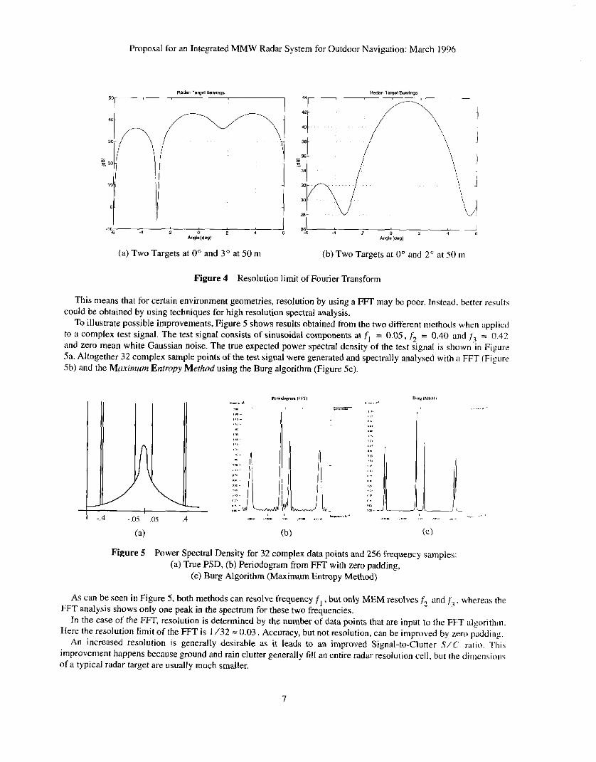
This means that for certain environment geometries, resolution by using a FFT may be poor. Instead. better results could be obtained by using techniques for high resolution spectral analysis.
To illustrate possible improvements, Figure 5 shows results obtained from the two different methods when ;ipplictl to 9 complex test signal. The test signal consists of sinusoidal components at f, = 0.05. ,5+ = 0.40 and = (1.42 and zero mean white Gaussian noise. The true expected power spectral density of the test ligna1 is shown.in Fisure 5a. Altogether 32 complex sample points of the test signal were generated and spectrally analysed with a FFT (Figure 5b) and the hlmin~um Entropy Method using the Burg algorithm (Figure 5c).
1 -.4 -.CIS .OS .4
Figure 5 Power Spectral Density for 32 complex data points and 256 frequency samples: (a) True PSD. (b) Periodogram from FFT with zero padding.
(c) Burg Algorithm (Maximum Entropy Method)
As can be seen i n Figure 5. both methods can resolve frequency f , . but only MEM resolves f, and fi. whereas the FFT analysis shows only one peak in the spectrum for these two frequencies.
In the case of the FFT. resolution is determined by the number of data points that are input to the FFT ;ilgorithin. Here the resolution limit of the FFT is I /32 = 0.03, Accuracy, but not resolution, can be improved by zero paddiiig.
An increased resolution is generally desirable as it leads to an improved Signal-to-Clutter S / C ratii). This improvement happens because ground and rain clutter generally fill an entire radar resolution cell. hut the ditnensioiis of a typical radar target are usually much smaller.
-
7
Proposal for an Integrated MMW Radar System for Outdoor Navigation: March 1996
It should be noted that here resolution is the ability of the system to distinguish between two sepxiitz tnrgctr thLit are close together. whereas accuracy i s the absolute accuracy with which a single tareet position can be detrlniincL
A complex signal may be needed in order to resolve the directional ambiguities for the Doppler criniponenl o t tlic signal. This can be obtained by either feeding the signal through a quadrature receiver or by using ii Hilbert Transform on the real signal and thus obtain the imaginary part. A single channel receiver element in cotnbin;itim with a Hilbert Transform has the advantage that phase and amplitude errors that occur i n a quadrature rcceiver do ]not have tn he considered.
2.4 Preliminary Results
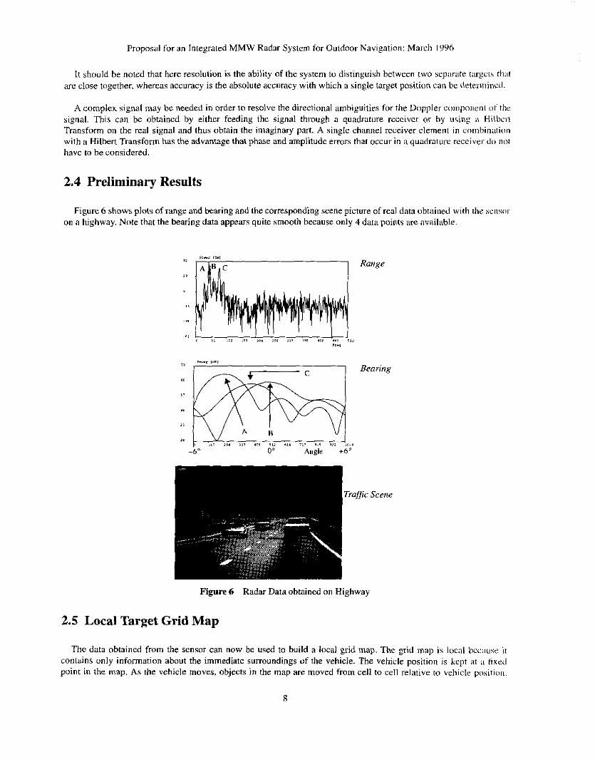
Figure 6 shows plots of range and bearing and the corresponding scene picture of real data obtained with the x n w on a highway. Note that the bearing data appears quite smooth because only 4 data paints are available.
Bearing
Figure 6 Radar Data obtained on Highway
2.5 Local Target Grid Map
The data obtained from the sensor can now be used to build a local grid map. The grid map is local bcuuse i t contains only information about the immediate surroundings of the vehicle. The vehicle position is !apt ;kt i l f ixed point in the map. As the vehicle moves, objects in the map are moved from cell to cell relative to \,chicle positioii.

Proposnl for an Integrated MMW Radar System for Outdoor Navigation: March 1906
Once an object falls outside the map boundary it is discarded and the information is lost. The map coi:ci~ the sei is~i t - ' \ field of view. using a variable resolution along x-axis and y-axis. In all. the map consists of 4 I x 101 cells. A s nbjecls get further away from the vehicle. a coarser map resolution is adequate. since sensor redings become lesr ;ICCLII:I~C.
However, coarse resolution map information is sufficient to plan initial navigation inaneuvres and perfom ~ a r ~ c r discrimination. As the object moves closer. navigation needs to be more precise and therefort! map remliitioti is increased. (See Figure 7).
Map Origin - *m
150.2 in
per cell ............................................. .- 50.2 m
Collision + Avoidance active in this region ............... 10.2 m
Regions monitored for obstacle avoidance
0.0
Figure 7 Local Grid Map
Each cell has a set of parameters or annotations associated with it, which are described below:
1. Object Type This parameter i s used to indicate if the object i n that cell was seen at the current sensor reading. oi- if it was seen at a previous reading. If it was seen only at a previous reading, then the ob.iect type indicnte.; t l ~ i i i
i t must have moved to that particular cell due to vehicle motion only. The parameter is also used to denote which type of sensor detected that particular ohject i t ' severxl different types of sensors are connected (e.g. sonar OT radar).
Indicates the x-y ps i t ion of the object with respect to vehicle position.
Indicates the relative velocity of the object towards the vehicle (Doppler velocily).
2. Position
3. Velocity
9

Proposal €or an Integrated MMW Radar System for Outdoor Navigation: March 1996
4. History This parameter counts the number of times an object u'as detected i n a particular cell
5 . Curvature Vector Is precomputed for each cell and denotes the range of steering arcs that would avoid ii collision hrtwceii the vehicle and an ob,ject in that cell.
The resolution of the grid is fairly coarse and hence a position parameter (X,,,,j. Y,!bi) is hcpr to avoid grew criw
Measurement uncertainty is part of the grid cell representation and any object detected within an artn CDVCI~X I,? ii
accumulation when objects are transformed in the map. Only one object is kept per gnd cell.
particular cell is taken to belong to the same object.
3 Integration with Road Geometry System
3.1 Problem Situations
In certain road environments, a false alarm situation may potentially arise. This is especially t h e case Yor- niultilarir. roads. undivided highways. curved roads and mads that are bordered by stationary objects such a5 guard trails or II-CW
It is therefore important to have some information about the road geometry the vehicle is driving ii i . On a stiiglil stretch of road. assignment of obstacles to particular lanes and areas off road and on road is simple. On uridividcil roads i t is, however, important to know whether an object in front of the vehicle is i n the vehicles own driving lmc ow in the lane for oncoming traffic or off road. If the road is curved then an additional difficulty is to detemiinc whctller an object is i n a neighbouring lane on a multilane road or the oncoming traffic lane or off mad. Typicd trxft ic situations are shown in Figure 8. A more detailed analysis of the geometry is given in Appendix C .
................................................
................................................. / n B
................................................ ?V- ..........................
... .... Guardrail
... .......................... r
(b)
Figure 8 Traffic situations leading to potential false alarms
In Figure 8b for example, vehicle A detects two targets ahead vehicle A and a portion of the guardrail. It i s obvious that neither object poses a threat if vehicle A stays in its current driving lane. However, a radar only bascrl W I S ( I ~
system will not be able to assess this situation properly without additional information about road geometry. As a tint step. information about steering radius from a steering encoder can be integrated. This will hclp to rejcci
clutter and improve performance when the vehicle is driving through a bend. However. since in this c:ise wc m l y know the current vehicle state but cannot look ahead, the traffic situation in Figure 8b still poses a problcni. Hcie ihc vehicle is still on a straight stretch of road and does not know yet of the curve ahead.
In the following sections. we will therefore describe two approaches for integrating additional informilfion.
3.2 Map based Solution
With the advance of technology in recent years, digital maps of many urban and non-urban areas i n tlic C L ) I I I I I ~

Proposal for an Integrated MMW Radar System for Outdoor Navigation: Morch 1996
have become auailable. Currently the best available resolution is approximately 12 metrcs. A typical map t ~ f th is kind is shown in Figure 9.
Figure 9 Digital Map of Urban Area (in Pittsburgh)
Different types of roads are shown. Each road is split into segments, represented hy a small number of positioii dati puints. By integrating such a map with a Global Positioning System (GPS), the position of the vehicle on the iniip ciin
be determined. With the given map resolution, individual lanes on a particular mad cannot be distinguished. but it i \ possible to look ahead and detect approaching curves and their curvature. Also, information on road structure. sucti iis the number of lanes, lane widths, divided highway, etc.. can be easily added. Then, i f we knuw in which Iiinc t h r vehicle is currently driving. it will be possible to match targets appropriately and distinguish betwcen tiit-sets i n different lanes and on road I off road targets.
It should be mentioned here that other research projects on autonornous vehicle control use huried lanc nizirker\ that are sensed inductively (PATH project). These could potentially also carry coded lane information. This ~ncthiul could be considered as another option. hut will not be a fucus in the proposed research.
3.3 Vision based Solution
Several vision systems using CCD cameras have been developed that can provide information abour rmd geometry. Two different approaches have been taken so far: One is road model based [ 6 ] , whereas the other is nwriil network based 191. Both systems are able to provide lane edge and centre positions. Figure I O shows il typical road scene as seen by a camera. Targets detected by the radar system then have tu hc matched to the road geometry as detected by a calibrated vision system. This can be efficiently donc by using ;I I ~ i d
grid map as a database. A framework that can be used for this purpose is described in section 2.5 (See i~lso [ X ] ) . ‘This information can then be used as input to higher level navigation functions for autonomous driving i n triittic.

Proposal for an Integrated MMW Radar System for Outdoor Navigation: hlarch 1996
Figure 10 Typical road scene with extracted lane geometry
4 Vehicle Velocity Control
The information contained in the local mge t grid map. integrated from radar and road geometry data. can now be used to control the vehicle velocity at a safe level. As mentioned in section 2.5: each cell of the grid map also ciii-!-its
precomputed information about the range of inhibited steering arcs if an obstacle would occupy that particular cell. 111 addition. we also know the length of arc that the vehicle would need to travel before colliding with an ohstncle in :I
pa~ticular map cell.
Figure 11 Steering Arc Evaluation
When moving through a cluttered environment, the velocity of the vehicle can now be controlled depcnding 011
distance to surrounding objects, current vehicle driving direction and geometry of the environment. In iidditioii. information can be provided on whether it is safe to initiate an overtaking maneuvre. This is especially useful on ii
two lane road with oncoming traffic. Figure I I shows the evaluation of a subset of steering arcs with respect to obstacles in the local grid map.
12

Proposal for an Integrated MMW Radar System for Outdoor Navigation: Mei-ch 19%
5 Research Agenda
The proposed research falls into the following a r e a :
I .
2.
Design and development of the millimeter wavr radar sensor.
Refinement of the radar sensor's resolution ability with high resolution spectral estimation techniclues
* Standard FFT. Maximum Entropy and Prony Method.
3. Integration with a road geometry system, based on a digital road map or lane marker detcction rhi-ouph ii video camera.
Target mapping and classification based on target properties such as signal strength. location and dop13ler velocity.
4.
* Clutter rejection
* Differentiation between on-road and off-road targets such as guardrail, trees. telephone poles
5. Integrating velocity control and providing driver information for several traffic scenarios:
* All road types: Detection of static and moving objects using doppler and range information. Mapping of targets to road lanes and off road objects. Ability to detect people and animals up to 60 m.
Multilane divided highway: Tracking vehicles in driving lane and adjacent lanes.
Two lane mral road: Detection of oncoming traffic i n opposite lane. (At long ranges, a vehicle in the opposite lane and a vehicle in the driving lane in front will both fall in the samc anguliir resolution cell.) Provide information to driver whether a safe overtaking maneuvre is possible. based on vehicle velocities and ranges.
City roads: Stop and go traffic. People crossing road
*
*
- 6. System performance evaluation for each of the above sections and demonstration on Navlab vchicles
Performance evaluation will be based on the number of false positive and negative alarms foi- ii given real world scenario in a controlled environment. This metric also serves as iui
improvement measure between a bare bones system and a system with the proposed additiunnl capabilities.
-
6 Contributions
The goal is to develop a sensing system capable of providing relevent information about the local kiftic situiitioii to an intelligent cruise control (ICC) or a human driver. The core of this system will be an integrated riidar sensor linked to a road geometry database. It will demonstrate techniques for radar target classification and clutter rejection As an improvement over current systems, it will be able to operale on a highway as well iis more CILI~ICI-C(I environments such as rural or city roads. At the moment, rural road accidents cause the largest nuinbcr of f:itiiliiic> and the largest total number of accidents occurs in city traffic.
The proposed radar sensor design will demonstrate the ability to achieve high resolution target position detectiw with a minimal amount of hardware and no mechanical scanning mechanism. Most other existing senwr dci;ii prototypes are restricted in their field of view and resolution as they use a limited number ofdiscrete multiplc beams.
The result of this thesis research will be a better driving system which will be achieved by integrating ;in improbecl radar sensor with road geomehy information.
13
Proposal for an Integrated MMW Radar System for Outdonr Navigation: Miirch 1990
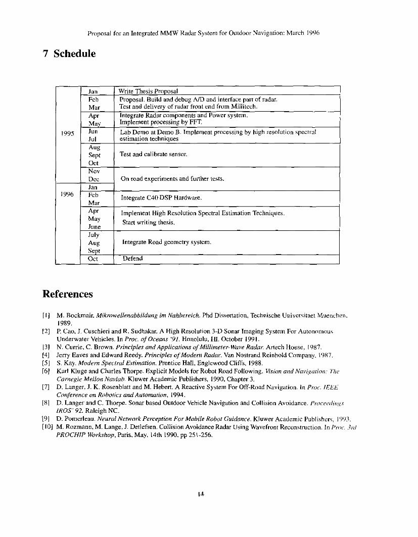
I Mar Tes; and delivery of radar-front end from Millkch. Integrate Radar components and Power system. Implement processing by FFT. Lab Demo at Demo B. Implement processing by high resolution specti-a1
APr May
1995 Juri Jul estimation techniques Aug Sept Test and calibrate sensor.
7 Schedule
1996
Jan 1 Write Thesis Proposal Feb I Prooosal. Build and debuz AID and interface Dart of radar.
N O V
Dec Jan Feb Mar APr May June July Aug Integrate Road geometry system. Sept or t Defend
On road experiments and further tests.
Integrate C40 DSP Hardware.
Implement High Resolution Spectral Estimatiun Techniques. Start writing thesis.
References
[ I ]
(21
131 141 [SI [6J
[71
181
191 [ IO] M. Rozmann, M. Lange. J. Detlefsen. Collision Avoidance Radar Using Wavefront Reconstruction. I n Proc. h i
M. Bockmair. MikmwelIenabbildung im Nahbrreich. Phd Dissertation. Technische Universiraet Muenchcn. 1989. P. Cao, J. Cuschieri and R. Sudhakar. A High Resolution 3-D Sonar Imaging Systein For Autoncliiinus Underwater Vehicles. In Proc. of Oceans '91. Honolulu, H I October I Y Y I. N. Currie, C. Brown. Principles and Applications .$Millimeter- Wave Radar. Artech House. 1987. Jerry Eaves and Edward Reedy. Principles of Modem Radur. Van Nostrand Reinhold Company. 1987. S. Kay. Mudem Spectral Estimarion. Prentice Hall, Englewood Cliffs, 1988. Karl Kluge and Charles Thorpe. Explicit Models for Robot Road Following. I.isiun aird Nmi,gurio,i: 7 % ~ Cnniegie Mellon Nuvlah. Kluwer Academic Publishers, 1990, Chapter 3. D. Langer, J. K. Rosenblatt and M. Hebert. A Reactive System For Off-Road Navigation. In Pro.. IEEL Conference on Robotics undAuromation. 1994. D. Langer and C. Thorpe Sonar based Outdoor Vehicle Navigation and Collision A\,oidance. Prur.eml;,,,i..~ IROS' 92. Raleigh NC. D. Pomerleau. Neural NemorkPerceprion Fur Mobile Robot Guidance. Kluwer Academic Publishers, 1993.
PROCHIP Workshop, Paris, May, 14th 1990, pp 251-256.

Proposal for an Integrated MMW Radar System for Outduor Navigation: March 1996
Appendix A
FMCW Millimeter Wave Radar
,____----__-___-_-_______________________ I I
77 GHz 'I
FM Linexiration
I I
500 kHz R
rv (4-
Law Pass I High P a s Antialiasing Filter I I / R ~ Fain R . .. . . . .. . . . .. .. .. . . . . . . . . .. 1. .. .. .. . . . . . . . . . . . . , , .. . . . . . . . . . . . . .
I 1 <- R I
I
I 1 I I
I 27dBi Cal 0
I S

Appendix B
System Parameters and Technical Specifications for the FMCW Radar
Carrier Frequency
Modulation Waveform
Swept Frequency
76.5 GHz
FMCW
300 MHz ~~~
Range Coverage Resolution Accuracy
Azimuth Coverage Resolution Nominal Accuracv
Elevation Coverage
1-200111 1 in 0. I m (or better)
12" 3" 0.1"
Range Rate Coverage Resolution Accuracy
Update Rate
Target Tracking
Antenna
Scanning Mechanism
Primary Power
Transmit Power
3"
20 Hz (configurable to 70 Hz for single target)
Yes
I Transmitter. 4 Receiver linear array VFoV: 3" , HFoV: 12' foreach Antenna
Wavefront reconstruction by spectral analyses. Angular resolution cell: 3" x 33
- 1 o o W
30 mW
-32 to +32 i d s 0.2 d s 3 mls
Modulation Cycle Time I ~ m s
Pmcessine Time I - 2 ms per tarzet
~
Data Interface I RS-232 and optionally S bit parallel
16

Proposal for an Integrated MMW Radar System for Outdoor Navigation: March I996
Appendix C
Minimum turn radius that keeps vehicle within FoV of sensor
The sensor is assumed to be mounted i n the centre of the vehicle. The minimum turning radius rlN,,, ic theii giver] by the following equations, where yPnr is the offset between sensor origin and vehicle origin P, M' is Ihc vchiclr width, HFoV is the horizontal field of view, m is the slope of the boundary line of the sensor field of view iinLl c . thc corresponding intercept. For simpler calculations the origin is taken at point 0
m = tan ( 90 -Hy) -
r . = - + m c + c ~ Z w rnrn 2
Using the dimensions of the Navlab vehicle and with HFoV = 12" , we get
r,",, = 251 m
The following values were used for the above calculation: 1v = 2.5 m Y ~ , , ~ = 1.5 m
(21

Proposal for an Integrated MMW Radar System for Outdoor Navigation: March 199h
Maximum road gradient
If the vertical field of view of the sensor VFoV = 3" and the sensor is mounted at a height :,,,<< = I 111 ;ihovc the ground, then the maximum gradient of the road that would still allow the sensor to see a target at R = 2 0 0 rii i \ given by.
VFoV h = z~ , ,~ + R . t a n - 2 z 6.2
which means that the gradient would be about 3.1 %
Geometric Analysis of different traffic scenarios
From the traffic scenario shown in Figure Sa. suppose that vehicles B and C are at 100 in dislance from \:ellick .L\ and we assume the lane width to b e 4 m. Then in order to resolve vehicles B and C a s two p o i n t targets, u'e 1ne4 to hc able to resolve an angular bearing of atan (4/100) = 2.3"
Fnim the traffic scenario shown in Figure Xb, we want to determine the radius of the cur\,e that would placs :I
vehicle B in the driving lane instead of the adjacent lane. We a s u m e that the curve starts 19 n i ahead 0 1 vcliiclc A. where the sensor's field of view just covers an entire lane.
If we place the centre of the curve at ( R , 0) and use the equation of a circle at p o i n t F, then the radius R of tlic curve is piven by: 2 2
R = - +' = 182.5 rn 2 r