proportional counters - pulsar.sternwarte.uni...
TRANSCRIPT

3–1
Proportional Counters
3–2
Introduction 1
Introduction
Before we can look at individual radiation processes, we need to understand how
the radiation is detected:
• Non-imaging detectorsDetectors capable of detecting photons from a source, but without any spatial resolution
=⇒ Require, e.g., collimators to limit field of view.
Example: Proportional Counters
• Imaging detectorsDetectors with a spatial resolution, typically used in the IR, optical, UV or for soft X-rays.
Generally behind some type of focusing optics.
Example: Charge coupled devices (CCDs)
Here: will concentrate on detectors for X-rays and optical light, starting withnon-imaging detectors.
3–3
Proportional counters 1
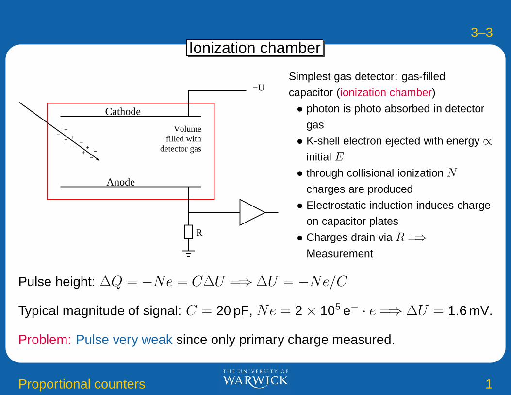
Ionization chamber
R
++
++
++
−−
−−
Cathode
Anode
−U
Volumefilled with
detector gas
Simplest gas detector: gas-filled
capacitor (ionization chamber)
• photon is photo absorbed in detector
gas
• K-shell electron ejected with energy ∝initial E
• through collisional ionization N
charges are produced
• Electrostatic induction induces charge
on capacitor plates
• Charges drain via R =⇒Measurement
Pulse height: ∆Q = −Ne = C∆U =⇒ ∆U = −Ne/C
Typical magnitude of signal: C = 20 pF, Ne = 2 × 10⁵ e− · e =⇒ ∆U = 1.6 mV.
Problem: Pulse very weak since only primary charge measured.
3–4
Proportional counters 2
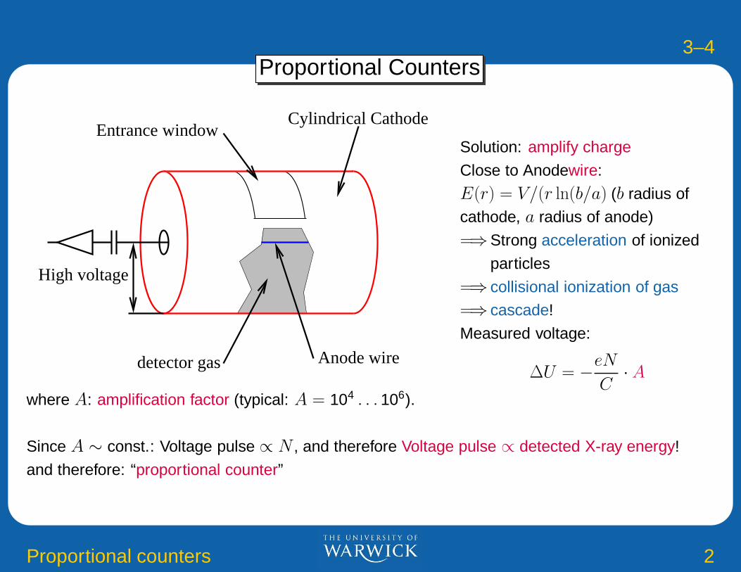
Proportional Counters
High voltage
detector gas Anode wire
Entrance windowCylindrical Cathode
Solution: amplify charge
Close to Anodewire:
E(r) = V/(r ln(b/a) (b radius of
cathode, a radius of anode)
=⇒Strong acceleration of ionized
particles
=⇒ collisional ionization of gas
=⇒ cascade!
Measured voltage:
∆U = −eN
C· A
where A: amplification factor (typical: A = 104 . . . 106).
Since A ∼ const.: Voltage pulse ∝ N , and therefore Voltage pulse ∝ detected X-ray energy!
and therefore: “proportional counter”

3–5
Proportional counters 3
Pulse Amplification
1014
Ionization chamber
Gei
ger
coun
ter
Num
ber
of c
olle
cted
ions
/ele
ctro
ns
Proportional−counter
proportionalityLimited
glow discharge
Recombination
0 250 500 750 1000 1250Voltage [V]
102
10
106
108
1010
10
4
12
(after Grupen, Fig.4.21)
Pulse amplification in detectoras a function of anode voltage.
Typical proportional counter
voltages are several 100 to1000 V (depending on
detector gas).

3–6
Proportional counters 4
Detector Gas
Use inert gases, e.g., Ar or Xe, since required voltage smallest and only low
losses due to excitation of the gas atoms.
Number of ions produced: N = E/ω, where ω is given by:
Gas H He Ne Ar Kr
ω [eV] 36.6 44.4 36.8 26.25 24.1
Gas Xe Air CO2 CH4
ω [eV] 21.9 35.2 34.2 29.1
=⇒ Typically N ∼ 1000 electron-ion pairs per 20 keV photon.
Note:
• probability for absorption σbf ∝ Z4...5 =⇒ use Xenon (Z = 54) forastronomical detectors
• since σbf ∝ E−3 =⇒ proportional counters limited to E < 100 keV.
3–7
Proportional counters 5
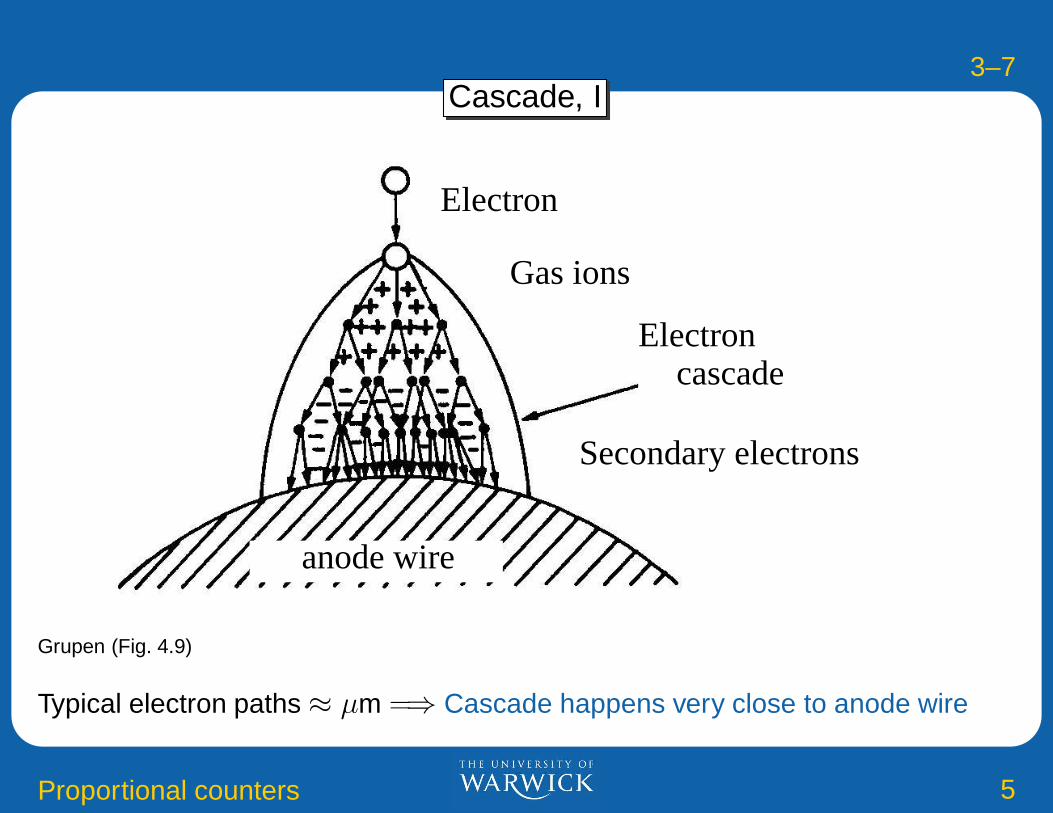
Cascade, I
Electron
Gas ions
Electron
Secondary electrons
cascade
anode wire
Grupen (Fig. 4.9)
Typical electron paths ≈ µm =⇒ Cascade happens very close to anode wire

3–8
Proportional counters 6
Cascade, II
Grupen (Fig. 4.27)
Electrons are accelerated to very high speeds towards wire, Ions are accelerated
away from wire
=⇒Main signal from ions, not electrons, since ions have larger potential
differencetypical duration of signal ∼ 100 µs, can reach higher time resolution by differentiating the signal

3–9
Proportional counters 7
Energy Resolution
Measured signal: pulse height =⇒ Energy of the X-ray
Resolution: ∆E: Width (=FWHM, Full Width at Half Maximum) of the distribution of measured
energies.
Poisson statistics (N discrete Electron-Ion pairs!):
∆E ∝ 2.35√
N ∝ 2.35√
E
Typically one uses ∆E/E
Slight correlations due to amplifying discharge =⇒ Width of distribution somewhat smaller than
expected from Poisson statistics =⇒ Fano Factor F :
∆E
E= 2.35
(
F
N
)1/2
where for gas detectors F ∼ 0.2–0.3
More detailed theory yields∆E
E= 2.35
(
W (F + A)
E
)1/2
W : mean energy to produce a pair (26 eV for Ar+Methane), F ∼ 0.2, A ∼ 0.6
=⇒ up to 14% at 5.9 keV doable.
3–10
Proportional counters 8
Quenching
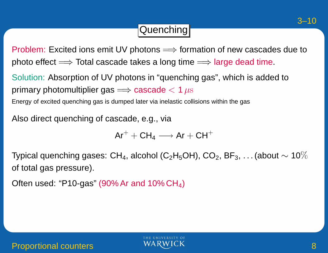
Problem: Excited ions emit UV photons =⇒ formation of new cascades due to
photo effect =⇒ Total cascade takes a long time =⇒ large dead time.
Solution: Absorption of UV photons in “quenching gas”, which is added toprimary photomultiplier gas =⇒ cascade < 1 µsEnergy of excited quenching gas is dumped later via inelastic collisions within the gas
Also direct quenching of cascade, e.g., via
Ar+ + CH4 −→ Ar + CH+
Typical quenching gases: CH4, alcohol (C2H5OH), CO2, BF3, . . . (about ∼ 10%
of total gas pressure).
Often used: “P10-gas” (90% Ar and 10% CH4)

3–11
Proportional counters 9
Ageing
Marko Spegel, 1999 (Diss. Uni Wien), J. Vavra, SLAC-3882
Cascade: plasma discharge =⇒ Destruction of gas contaminants =⇒ formation of free radicals =⇒polymerizationPolymers have high dipole moment =⇒ attach to electrodes =⇒ Reduction of pulse charges =⇒ “Ageing”Typical contaminants: carbon, oxide-layers, silicates, e.g., from oil, finger grease, Silan (SiH4), solvents invacuum sealants,. . .Results in field electron emission through photo-effect =⇒ discharge =⇒ wire destroyed (“Malter-Effekt”)Most sensitive proportional counter gas: Ar/CH4. . .

3–12
Proportional counters 10
Example: RXTE-PCA
HEXTE A B
PCA(1 of 5)
ASM
Rossi X-ray Timing Explorer
Rossi-X-ray Timing Explorer, Launch
30.12.1995, 3 instruments:• Proportional Counter Array (PCA,
2–100 keV),• High Energy X-ray Timing
Experiment (HEXTE,
15–250 keV),• All Sky Monitor (ASM, 2–10 keV)
PCA and HEXTE have µsec timingresolution

3–13
Proportional counters 11
Example: RXTE-PCA
3–14
Proportional counters 12
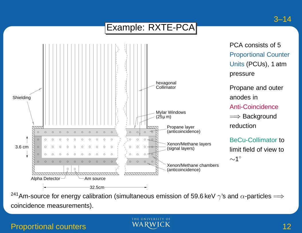
Example: RXTE-PCA
hexagonalCollimator
Propane layer(anticoincidence)
Xenon/Methane layers(signal layers)
(anticoincidence)Xenon/Methane chambers
(25 m)Mylar Windows
µ
32.5cm
� � � � � � � � � � � � � � � � � � � � � � �
� � � � � � � � � � � � � � � � � � � � � � �
� � � � � � � � � � � � � � � � � � � � � � �
� � � � � � � � � � � � � � � � � � � � � � �
� � � � � � � � � � � � � � � � � � � � � � �
� � � � � � � � � � � � � � � � � � � � � � �
� � � � � � � � � � � � � � � � � � � � � � �
� � � � � � � � � � � � � � � � � � � � � � �
� � � � � � � � � � � � � � � � � � � � � � �
� � � � � � � � � � � � � � � � � � � � � � �
� � � � � � � � � � � � � � � � � � � � � � �
� � � � � � � � � � � � � � � � � � � � � � �
� � � � � � � � � � � � � � � � � � � � � � �
� � � � � � � � � � � � � � � � � � � � � � �
� � � � � � � � � � � � � � � � � � � � � � �
� � � � � � � � � � � � � � � � � � � � � � �
� � � � � � � � � � � � � � � � � � � � � � �
� � � � � � � � � � � � � � � � � � � � � � �
� � � � � � � � � � � � � � � � � � � � � � �
� � � � � � � � � � � � � � � � � � � � � � �
� � � � � � � � � � � � � � � � � � � � � � �
� � � � � � � � � � � � � � � � � � � � � � �
� � � � � � � � � � � � � � � � � � � � � � �
� � � � � � � � � � � � � � � � � � � � � � �
� � � � � � � � � � � � � � � � � � � � � � �
� � � � � � � � � � � � � � � � � � � � � � �� � � � � � � � � �
� � � � � � � � � �
� � � � � � � � � �
� � � � � � � � � �
� � � � � � � � � �
� � � � � � � � � �
� � � � � � � � � �
� � � � � � � � � �
� � � � � � � � � �
� � � � � � � � � �
� � � � � � � � � �
� � � � � � � � � �
� � � � � � � � � �
� � � � � � � � � �
� � � � � � � � � �
� � � � � � � � � �
� � � � � � � � � �
� � � � � � � � � �
� � � � � � � � � �
� � � � � � � � � �
� � � � � � � � � �
� � � � � � � � � �
� � � � � � � � � �
� � � � � � � � � �
� � � � � � � � � �
� � � � � � � � � �3.6 cm
Am source
Shielding
Alpha Detector
PCA consists of 5
Proportional Counter
Units (PCUs), 1 atm
pressure
Propane and outer
anodes in
Anti-Coincidence
=⇒ Background
reduction
BeCu-Collimator to
limit field of view to
∼1◦
241Am-source for energy calibration (simultaneous emission of 59.6 keV γ’s and α-particles =⇒coincidence measurements).
3–15
Proportional counters 13
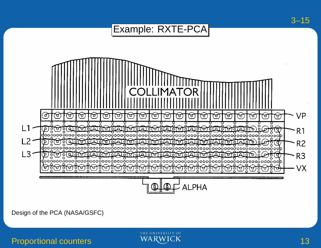
Example: RXTE-PCA
Design of the PCA (NASA/GSFC)

3–16
Proportional counters 14
Example: RXTE-PCA
RXTE-PCA
10 100PHA Channel Energy [keV]
1
10
100
Pho
ton
Ene
rgy
[keV
] Response matrix:
Relation betweenincident photon
energy and detectionchannel.
Resolution: 18% at
6 keV
Escape-Peaks caused by Xe Kα (E = 29.46 keV) and Xe Lα (E = 4.11 keV)photons leaving the detector without being detected.

3–17
Proportional counters 15
Example: RXTE-PCA
. . . this is what happens once a Mylar window starts having a hole in spaceIn addition ageing =⇒ Reduction of high voltage, alternate use of different PCUs.