properties of oriented strand board (osb), and timber …
TRANSCRIPT
EMM654-1
Leadership in Sustainable Infrastructure
Leadership en Infrastructures Durables
Vancouver, Canada
May 31 – June 3, 2017/ Mai 31 – Juin 3, 2017
PROPERTIES OF ORIENTED STRAND BOARD (OSB), AND TIMBER
TO EVALUATE THE STIFFNESS OF TIMBER I-JOIST
M. Shahidul Islam1,4, Mohammad Nouroz Islam2, M. Shahria Alam3,
1 Graduate Student, University of British Columbia, Kelowna, BC, V1V 1V7, Canada
2 Mechanical Engineer, Dish structures, NRC Herzberg Astronomy and Astrophysics, National
Research Council Canada, 717 White Lake Road PO Box 248 Penticton, BC, V2A 6J9, Canada
3 Associate Professor, University of British Columbia, Kelowna, BC, V1V 1V7, Canada
Abstract:
Timber I-joist is an engineered building construction element produced from solid timber and Oriented Strand Board (OSB) as flange and web, respectively. In Canada, timber I-joists are commonly used for construction of residential and industrial buildings. This research study was conducted to evaluate the different mechanical properties of OSB and timber. The Ultimate strengths, Modulus of Elasticity (E), Shear Modulus of Elasticity (G), and Poisson’s ratio were investigated under tension loading as per specified standard (ASTM-D1037 and ASTM-D143). Based on these mechanical properties of OSB, and timber, the combined stiffness of composite I-joist was determined and compared to the overall stiffness (K) of the tested I-joist under four points bending test. It is found that a good agreement exists between the flexural stiffness derived from the material properties and bending test. Finally, calculated stiffness and measured stiffness based on the four point bending test of I-joists were compared and it is found that the calculated values of stiffness (KA) are very close to the experimental stiffness (KE).
Keywords: Timber, I-joist, Oriented Strand Board, Modulus of Elasticity, Poisson’s Ratio
1.1 Introduction
Composite I-joists are an engineered wood products with a cross section of “I” shaped containing a web and two flanges referred as top & bottom flange. Top & bottom flanges are connected with a relatively thin web. Typically flanges are made of solid lumber or structural composite lumber (SCL) such as laminated veneer lumber (LVL) or parallel strand lumber (PSL). Whereas, Oriented Strand Board (OSB) is the most common materials and occasionally ply wood used as the web materials. Oriented Strand Board (OSB) is a wood based engineering panel product. OSB has various applications in manufacturing other engineering products and construction related products, such as I-joists, floor & roof sheathing, shear wall panels etc.

EMM654-2
Hence, OSB exhibits mechanical properties similar to those of wood. For example, OSB behaves elastically
and elasto-plastically when it is subjected to the tension and compression, respectively (Zhu et al. 2005).
Characteristic stress-strain relationships of timber, OSB, and GFRP are essential for the analytical and numerical analysis of structures containing OSB panels, timber and Glass Fiber Reinforced Polymer (GFRP). However, most of the available literature focused only on the ultimate strength of these materials and did not consider the non-linearity or plasticity in the relationships. The objective of this Chapter is, therefore, to obtain material properties of OSB, and Timber, which could help develop constitutive models for analytical and numerical analysis. The objectives of this research study is evaluation of the material properties of OSB, and Timber to determine the stiffness of timber I-joist made with OSB as web material and Timber as flange material.
1.2 Experimental Program
To investigate the strength, elastic modulus and Poisson’s ratio of OSB, tension test of OSB was conducted in three in-plane directions of the OSB panel, which are longitudinal (along strong axis of the panel), transverse (perpendicular to the strong axis) and Diagonal (450 with the strong axis) direction as demonstrated in Figure 1. Four specimens from each direction were prepared from a standard 1220x2400mm OSB panel. Three specimens were used for data analysis and the test results from 4 th specimen was used for the validation of the constitutive model. All tested specimens were prepared from the materials which were sampled directly from the I-joist manufacturing product line at AcuTruss Industries Ltd., in Kelowna, BC, Canada.

EMM654-3
(a) Direction of OSB Test Specimens
(b) Dimensions of OSB Coupon
Figure 1: Details of OSB coupon specimen for tension test.
A bi-axial strain gauge was used to capture the strain along the loading direction (X-axis) and the transverse direction (Y-axis) of the coupon specimens (OSB, Timber, GFRP) subjected to the tension load as shown in Figure 2. Gauge length and resistance of the used strain gauges was 50 mm and 120Ω, respectively. Tension test was performed by using Instron universal testing machine with a capacity of 250 kN, where the load was applied hydraulically during the test at a constant rate of 4mm/min, as specified in the ASTM-D1037 (2014). All specimens were prepared from the samples picked from the I-joist manufacturer product line, to ensure the randomness of the samples.
45o
Panel Strong Axis
Tra
ns
ve
rse
Longitudinal
Y
X
Y
X
70 mm 45 mm80 mm45 mm 70 mm
60
15
15
SG
OSB Coupon SpecimenSG- Strain Gauge
Y
X

EMM654-4
Figure 2 Sample of a OSB Tension test specimen with a Bi-axial Strain Gauge
1.2.1 Properties of OSB
Strengths, elastic modulus and Poisson’s ratios of OSB in three in-plane directions of the OSB panel (Longitudinal, Transverse and Diagonal) were determined by conducting tension test in three different directions.
Longitudinal Direction
Figure 3 shows stress-strain curves for OSB subjected to tension along the longitudinal direction of the OSB panel. All stress-strain curves exhibit linear behavior at the initial stage followed by plastic behavior. Summary of tension test results of OSB in longitudinal direction are summarized in Table 1. Average strength and modulus of elasticity in longitudinal direction was found to be 16.84 MPa and 5738 MPa, respectively. Average Poisson’s ratio (νLT) was found to be 0.309. The Poisson’s ratio obtained from the specimen OSB-L-02 was discarded as the strain gauge perpendicular to the loading direction was de-bonded just after starting the test.
Table 1 Summary of the Tension test of OSB in Longitudinal Direction
Specimen ID. Max. σx Max. εx Max. εy MOE νXY or
νLT (MPa) (mm/mm) (mm/mm) (MPa)
OSB-L-01 16.80 4.36E-03 -7.83E-09 5057.7 0.3479
OSB-L-02 16.06 2.69E-03 -3.88E-09 5417.01
OSB-L-03 17.65 3.77E-03 -4.37E-08 5493.09 0.27007
Average 16.84 3.61E-03 -1.85E-08 5322.60 0.3090
SD 0.80 8.45E-04 2.20E-08 232.54 0.0550
COV 5% 23% -119% 4% 18%

EMM654-5
(a) Tested OSB Specimens along Strong Axis (Longitudinal direction)
(b) Stress-Strain Response of OSB subjected to tension along strong axis (Longitudinal direction)
Figure 3 Stress-strain response of OSB subjected to tension along the strong axis of the OSB panel.
Transverse Direction
Strength, Modulus of Elasticity and Poisson’s ratio of OSB in transverse direction (perpendicular to strong axis) is also required to understand the behavior of OSB. Average strength and modulus of elasticity of OSB along panel transverse direction was obtained to be 12.51MPa and 3231 MPa, respectively. The average Poisson’s ratio (νTL) was found to be 0.14628 with a 1% COV. Acquired data obtained from the strain gauge attached perpendicular to the loading direction had an error reading due to early de-bonding of the gauge, hence the Poisson’s ratio obtained from the OSB-T-03 has been considered as an outlier. The summary of the tension test along the panel transverse direction has been presented in Figure 4 and Table 2.
From Figure 4 it can be observed that the stress-strain relationships behave elasto-plastically for OSB subjected to the tension in transverse direction of the OSB panel. However, Zhu et al. (2005) found that OSB behaves liner-elastically under tension in panel transverse direction.

EMM654-6
Table 2 Summary of the Tension test of OSB in Transverse Direction
Specimen ID. Max. σx Max. εx Max. εy MOE νXY or
νTL (MPa) mm/mm) (mm/mm) (MPa)
OSB-T-01 13.64 5.96E-03 -2.22E-08 3341.33 0.14525
OSB-T-02 12.09 6.73E-03 -5.23E-08 2850.75 0.14731
OSB-T-03 11.81 4.54E-03 -2.34E-08 3499.95
Average 12.51 5.75E-03 -3.26E-08 3230.68 0.1463
SD 0.98 1.11E-03 1.71E-08 338.45 0.0015
COV 8% 19% -52% 10% 1%
(a) Tested OSB Specimens (Transverse direction)
(b) Stress-Strain Response of OSB subjected to tension along Transverse direction
Figure 4 Stress-strain response of OSB subjected to tension along the Transverse direction of the OSB panel.

EMM654-7
Diagonal Direction
To understand the shear properties of OSB panel, tension test in diagonal direction (45o with the strong axis) has been performed. The summary of the tension test along the panel transverse direction has been presented in Figure 5 and Table 3.
(a) Tested OSB Specimens (Diagonal (D450) direction)
(b) Stress-Strain Response of GFRP subjected to tension along Diagonal (D450) direction
Figure 5 Stress-strain response of OSB subjected to tension along Diagonal (45o) direction of the OSB panel.
These results presented above show that the tested Oriented Strand Board (OSB) has engineering properties comparable with those found by Chui et al. (2005) for similar materials, and by (Zhu 2003) for OSB web of British I-joists. However, the obtained MOE at longitudinal direction is higher whereas, it is lower at transverse direction compared to those reported by Karacabeyli et al. (1996) for structural grade Canadian OSB. These dissimilarities were unexpected, considering the same evaluated products. In contrast, the MOE obtained by Grandmont et al. (2010a) was lower than the obtained results for both directions.

EMM654-8
Table 3 Summary of the Tension test of OSB in Diagonal (45o) Direction
Specimen ID. Max. σx Max. εx Max. εy MOE νXY or
νD45 (MPa) (mm/mm) (mm/mm) (MPa)
OSB-D45-01 17.92 4.25E-03 -2.62E-08 3385.1 0.20098
OSB-D45-02 12.65 3.92E-03 -6.89E-08 3656.6 0.25888
OSB-D45-03 9.98 1.97E-03 -6.69E-08 4068.2 0.28457
Average 13.52 3.38E-03 -5.40E-08 3703.3 0.2481
SD 4.04 1.23E-03 2.41E-08 343.9 0.0428
COV 30% 36% -45% 9% 17%
1.3 Properties of Timber
To evaluate the engineering properties of timber, tension test was performed according to ASTM-D143 (2014). The details of the timber tension test specimen are presented in Figure 6. Figure 7 shows stress-strain curves for timber (SPF) subjected to tension load parallel to the fiber direction of the flange material. All stress-strain curves exhibit linear behavior at the initial stage followed by plastic behavior. Summary of tension test results of timber along fiber direction are summarized in Table 4. Average strength and modulus of elasticity along fiber direction was found to be 57.02 MPa and 17699.42 MPa, respectively. Average Poisson’s ratio (ν) was found to be 0.325 with a co-efficient of variation (COV) of 21%. From the stress-strain (Transverse, εy) response of the tension test (Figure 7), the crack initiation stage was identified and found to be at a stress of 30.37 MPa with a COV of 6%.
Figure 6 Details of Timber coupon specimen for tension test.
70 mm 45 mm80 mm45 mm 70 mm
12
12
12
70 mm 45 mm80 mm45 mm 70 mm
50
6.5
6.5
SG
Timber Coupon SpecimenSG- Strain Gauge
Y
X
Top View
Side View

EMM654-9
Table 4 Summary of the Tension test of Timber subjected to tension parallel to fiber
Specimen ID.
Max. σx Crack Initiation
Stress Max. εx Max. εy MOE νXY or νP
(MPa) (MPa) (mm/mm) (mm/mm) (MPa)
SPF-P-01 47.42 32.1 5.69E-03 -1.01E-07 14993.87 0.32333
SPF-P-02 55.89 30.3 3.80E-03 -1.05E-07 16766.29 0.39316
SPF-P-03 67.75 28.7 4.03E-03 -1.90E-07 16427.41 0.2585
Average 57.02 30.37 4.51E-03 -1.32E-07 16062.52 0.3250
SD 10.21 1.70 1.03E-03 5.02E-08 940.86 0.0673
COV 18% 6% 23% -38% 6% 21%
(a) Tested Timber Specimens (SPF) subjected to tension parallel to fiber
(b) Stress-Strain Response of Timber subjected to tension parallel to fiber
Figure 7 Stress-strain response of Timber subjected to tension parallel to fiber
EMM654-10
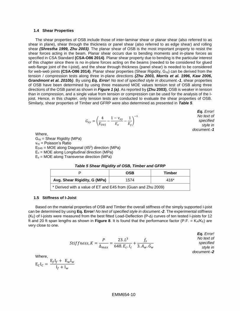
1.4 Shear Properties
The shear properties of OSB include those of inter-laminar shear or planar shear (also referred to as shear in plane), shear through the thickness or panel shear (also referred to as edge shear) and rolling shear (Shrestha 1999, Zhu 2003). The planar shear of OSB is the most important property to resist the shear forces acting in the beam. Planar shear occurs due to bending moments and in-plane forces as specified in CSA Standard (CSA-O86 2014). Planar shear property due to bending is the particular interest of this chapter since there is no in-plane forces acting on the beams (needed to be considered for glued web-flange joint of the I-joist), and the shear through thickness (panel shear) is needed to be considered for web-web joints (CSA-O86 2014). Planar shear properties (Shear Rigidity, Gxy) can be derived from the tension / compression tests along three in-plane directions (Zhu 2003, Morris et al. 1996, Kaw 2006, Grandmont et al. 2010b). By using Eq. Error! No text of specified style in document.-1, shear properties of OSB have been determined by using three measured MOE values tension test of OSB along three directions of the OSB panel as shown in Figure 1 (a). As reported by (Zhu 2003), OSB is weaker in tension than in compression, and a single value from tension or compression can be used for the analysis of the I-joist. Hence, in this chapter, only tension tests are conducted to evaluate the shear properties of OSB. Similarly, shear properties of Timber and GFRP were also determined as presented in Table 5.
𝐺𝑥𝑦 = (4
𝐸𝐷45
−1 − 𝜈𝑥𝑦
𝐸𝑥
−1
𝐸𝑦
)
−1
Eq. Error! No text of specified
style in document.-1
Where, Gxy = Shear Rigidity (MPa) νxy = Poisson’s Ratio ED45 = MOE along Diagonal (450) direction (MPa) Ex = MOE along Longitudinal direction (MPa) Ey = MOE along Transverse direction (MPa)
Table 5 Shear Rigidity of OSB, Timber and GFRP
P OSB Timber
Avg. Shear Rigidity, G (MPa) 1574 416*
* Derived with a value of ET and E45 from (Guan and Zhu 2009)
1.5 Stiffness of I-Joist
Based on the material properties of OSB and Timber the overall stiffness of the simply supported I-joist can be determined by using Eq. Error! No text of specified style in document.-2. The experimental stiffness
(KE) of I-joists were measured from the best fitted Load-Deflection (P-Δ) curves of ten tested I-joists for 12
ft and 20 ft span lengths as shown in Figure 8. It is found that the performance factor (P.F. = KA/KE) are very close to one.
𝑆𝑡𝑖𝑓𝑓𝑛𝑒𝑠𝑠, 𝐾 =𝑃
∆𝑚𝑎𝑥=
23. 𝐿3
648. 𝐸𝑐 . 𝐼𝑐+
𝑓𝑠
3. 𝐴𝑤 . 𝐺𝑤
Eq. Error! No text of specified
style in document.-2
Where,
E𝐶I𝐶 = E𝑓I𝑓 + E𝑤I𝑤
I𝑓 + I𝑤

EMM654-11
P = Load (N); L = Span Length (m); Aw = Area of Web (m2); Gw = Shear Rigidity of OSB (MPa); If, IW = Moment of Inertia of flange, web (m4); Ef = MOE of Flange, i.e. Timber (MPa); Ew = MOE of Web, i.e. OSB (MPa); fs = Form Factor
(a) 12 ft I-Joists (b) 20 ft I-Joists
Figure 8 Comparison of Calculated Stiffness (KA) with the Experimental Stiffness (KE)
1.6 Conclusions
• From the tension tests conducted, it was observed that under tension OSB exhibits the weakest and the strongest mechanical behaviour in the transverse and longitudinal directions, respectively, while properties along the diagonal directions are in between the longitudinal and transverse directions.
• Constitutive models can be developed based on this test results for analysing the performance and predicting the load carrying capacity of I-joist.
• Calculated stiffness of I joists are very close to the stiffness obtained from the four point bending test.
1.7 REFERENCES
ASTM-D1037. (2014). “Standard Test Methods for Evaluating Properties of Wood-Base Fiber and Particle.” ASTM International, West Conshohocken, PA, 2014.
ASTM-D143. (2014). “Standard Test Methods for Small Clear Specimens of Timber.” ASTM International, West Conshohocken, PA, 2014.
Chui, Y. H., Pirzada, G., and Lai, S. (2005). Enhancing Shear and Bearing Strength of Wood I-joists.
CSA-O86. (2014). “CSA O86- Engineering Design in Wood.” Canadian Standards Association, 2014.
Grandmont, J.-F., Cloutier, A., Gendron, G., and Desjardins, R. (2010b). “Effect of Density on the Properties of Oriented Strandboard Web Stock Used in Wood I-Joists.” Forest products journal, 60(7/8), 592–598.
Grandmont, J.-F., Cloutier, A., Gendron, G., and Desjardins, R. (2010a). “Wood I-Joist Model Sensitivity to Oriented Strandboard Web Mechanical Properties.” Wood and Fiber Science, 42(3), 352–361.
Guan, Z. W., and Zhu, E. C. (2009). “Finite element modelling of anisotropic elasto-plastic timber composite beams with openings.” Engineering Structures, Elsevier Ltd, 31(2), 394–403.
P (Exp.) = 1.146 Δ
R² = 0.9839
0
5
10
15
20
25
30
35
40
45
50
0 10 20 30 40 50
P (
kN
)
ΔL/2 (mm)
12-A
Analytical
Experimental
Best Fitted (Exp.)
PF = KA/KE = 0.98
P(Exp.) = 0.2954 Δ
R² = 0.909
0
5
10
15
20
25
30
35
0 10 20 30 40 50 60 70 80 90 100 110
P (
kN
)
ΔL/2 (mm)
20-A
Analytical
Experimental
Best Fitted (Exp.)
PF = KA/KE = 1.03

EMM654-12
Karacabeyli, E., Lau, P., Henderson, C. R., Meakes, F. V, and Deacon, W. (1996). “Design rated oriented strandboard in CSA standards.” 443, 431–443.
Kaw, A. K. (2006). Mechanics of Composite Materials. Taylor & Francis Group, LLC.
Morris, V., Gustaffson, P., and Serano, E. (1996). “The shear strength of lightweight beams with and without a hole-A preliminary study.” Wood mechanics: Workshop on mechanical properties of panel products, 22-23 March 1995, Watford, UK., 199–214.
Shrestha, D. (1999). “Shear Properties tests of oriented strandboard panels.pdf.” Forest products journal, 49(10), 41–46.
Zhu, E. (2003). “Modelling the structural behaviour of OSB webbed timber I-beams.” PhD Thesis, University of Brighton, UK.
Zhu, E. C., Guan, Z. W., Rodd, P. D., and Pope, D. J. (2005). “A constitutive model for OSB and its application in finite element analysis.” Holz Roh- Werkst, 63(2), 87–93.