propagation of 2 ghz radio waves over the english channel ...propagation of 2 ghz radio waves over...
TRANSCRIPT

Propagation of 2 GHz Radio Waves Over the English Channel: Analysis of Cases of Sub-Refraction
S.D. Gunashekar1, E.M. Warrington1, D.R. Siddle1
1Department of Engineering, University of Leicester, Leicester LE1 7RH, U.K. (E-mail: [email protected])
Abstract
This paper presents details about the transhorizon propagation of 2 GHz radio waves over the sea during sub-refractive atmospheric conditions. Sub-refraction is perhaps the most rare of the four refractive conditions (ducting, super-refraction, normal refraction and sub-refraction), but nevertheless cannot be ignored when assessing the performance of a radio link. Specifically, for a 50 km, low-altitude, over-sea radio path in the British Channel Islands, an attempt has been made to model the propagation conditions during periods of sub-refraction, and the results compared with experimental observations.
1. Introduction
Between August 2003 and August 2005, three completely over-sea propagation paths (at 2 GHz) were established in the British Channel Islands. These were between Jersey and Alderney (48.5 km), Jersey and Guernsey (33.5 km) and Jersey and Sark (21.0 km). Each site had two antennas: low antennas at 14.5 m (Jersey), 10.0 m (Alderney), 10.0 m (Guernsey) and 10.0 m (Sark) above mean sea level and high antennas at 17.5 m (Jersey), 13.0 m (Alderney), 14.0 m (Guernsey) and 13.0 m (Sark) above mean sea level. Signal strength measurements were made using alternately the high and the low antennas.
Hourly sea-level marine meteorological data were obtained from the Channel Light Vessel (CLV) anchored
in the English Channel to the northwest of all the radio paths. Higher altitude weather data were also obtained from various land-based weather stations located around the Channel Islands (La Petit Val, Alderney: 10.7 m above mean sea level, Maison St. Louis Observatory in St. Helier, Jersey: 54.0 m above mean sea level, Jersey Airport: 84.0 m above mean sea level, Alderney Airport: 88.7 m above mean sea level and Guernsey Airport: 102.0 m above mean sea level). Further details of the experimental set-up can be found in previously published papers [1, 2]. There are possibly two distinct propagation mechanisms taking place on the transhorizon Jersey-Alderney link [1, 2]: evaporation ducting and diffraction for the majority of the time, and higher-level super-refractive/ducting structures for brief periods when the received signal strengths exceed a threshold calculated assuming free space loss along the path. The latter have been termed as periods of enhanced signal strength. This paper presents details about the transhorizon propagation of 2 GHz radio waves over the English Channel during sub-refractive atmospheric conditions. In particular, an attempt has been made to model the propagation conditions during periods of sub-refraction, and the results compared with experimental observations.
2. Theoretical Background
On the basis of the average rate at which the refractivity (N) of the troposphere varies with height within
the first 1 km of the earth’s surface (i.e. the refractivity gradient, dN/dh), four basic atmospheric conditions may be defined: sub-refraction, normal refraction, super-refraction and trapping (or ducting). Depending on the existing conditions in the troposphere, a radio wave will undergo any of the four types of refraction.
Under normal atmospheric conditions, using Snell’s law, a radio ray projected into the atmosphere will
have to travel from a denser to more rarefied medium and will refract downwards towards the surface of the earth. The curvature of the ray, however, will still be less than the earth’s curvature. The gradient of refractivity in this case generally varies from 0 to –79 N-units per kilometre, and the atmospheric condition is referred to as being normal. A standard atmosphere is defined as one in which the value of N decreases at a rate of approximately 40 N-units per kilometer [3, 4].

When the refractivity gradient, dN/dh is within the range –79 to –157 N-units per kilometre, a super-refractive condition is said to prevail in the troposphere and the ray will refract downwards at a curvature greater than normal but less than the curvature of the earth [3, 4].
A refractivity gradient that is less than –157 N-units per kilometre will result in a ray that refracts towards
the earth’s surface with a curvature that exceeds the curvature of the earth. This situation is referred to as trapping or ducting, and is the phenomenon that occurs, for instance, in the different kinds of tropospheric duct propagation [3, 4]. Ducting and super-refraction are normally associated with enhanced signal propagation.
Finally, if dN/dh is greater than 0 N-units per kilometre, a sub-refractive condition exists and a radio ray
will now refract upwards, away from the surface of the earth. During periods of sub-refraction, there may be occasions when the bulge of the earth causes the direct path between the transmitter and receiver to be obscured, resulting in a considerable decrease in the received signal strength. In this situation, diffraction around the earth’s curvature is the dominant propagation mechanism. Sub-refraction is perhaps the most rare of the four refractive conditions, but nevertheless cannot be ignored when assessing the performance of a radio link.
3. Observations and Analysis
The Paulus-Jeske (P-J) [5] evaporation duct heights were estimated from the hourly weather data obtained from the CLV (air temperature, sea temperature, relative humidity and wind speed). While computing the modified refractivity (M) profiles corresponding to the Paulus-Jeske evaporation duct using meteorological data from the CLV, there are 335 cases of sub-refraction for which the evaporation duct height was calculated to be zero (note: the modified refractivity, M = N + (0.157 x h) where N is the atmospheric refractivity in N-units and h is the height above sea level in metres). All but 4 of these cases occur during the spring or summer months. Compared to the overall mean of the high antenna signal strength at the Alderney high antenna (-87.5 dBm), the mean signal strength observed during the sub-refractive events is -96.7 dBm, showing a marked decrease in the received signal strength during this period.
During sub-refraction, the atmospheric refractivity (N), and consequently the modified refractivity (M) increase with height (i.e. dN/dh > 0 N-units/km or dM/dh > 157 M-units/km). A typical modified refractivity-height profile for a sub-refractive case on 01 June 2005 at 16:00 UT (transmitter height = 16.1 m) is shown in Figure 1 (left frame). The P-J formulation [5] has been used to determine the profile using weather data from the Channel Light Vessel. Clearly, there is no evaporation duct present. The resultant tropospheric ray-trace diagram (generated in AREPS [4]) for this example sub-refractive environment is also presented (Figure 1, right frame). The upwardly refracting rays and the absence of a low-level evaporation duct are apparent.
Figure 1: Sample height vs. modified refractivity profile during a period of sub-refraction on 01 June 2005 at 16:00 UT (using weather data from the Channel Light Vessel) (left frame) and the corresponding height vs. range ray-trace plot with the transmitter placed at 16.1 m (right frame).

The corresponding monotonically increasing M profiles for all the cases of sub-refraction were used as input to predict the received signal strength using the parabolic equation method (PEM). However, the correlation between the observed and predicted signal strengths at the Alderney high antenna is not very good (though the shapes of the curves match up for a number of the cases) (Figure 2, left frame). Note that the sub-refractive profiles are computed according to the Paulus-Jeske method by simply using the surface values of air temperature, sea temperature, wind speed and relative humidity. Values of refractivity at higher altitudes (using weather data from the land-based stations at various locations around the Channel Islands) are not used to determine the refractivity gradients in this instance.
Since sub-refractive atmospheric conditions are being considered, it is most likely that the propagation
mechanism involved is simple diffraction. In order to confirm this, the measured signal strengths during the periods of sub-refraction were compared to the corresponding signal strengths computed using ITU-R Recommendation P.526 [6] (i.e. diffraction over a spherical earth) (Figure 2, right frame). There is reasonably good correlation between the observed and predicted signal strengths for the majority of the cases.
Despite providing convincing verification of the importance of super-refraction and ducting in the context
of transhorizon over-sea propagation ([1, 2]), some care should be taken while interpreting the effect of low-altitude refractivity lapse rates (from multiple diversely located meteorological sources) on radiowave propagation. For instance, by simply using the refractivity lapse rate as determined from the different weather stations around the Channel Islands, there are 439 cases of sub-refraction (the refractivity lapse rate was determined by finding the slope of the best-fit line through points on the refractivity vs. height plot for hourly data from the various meteorological stations). Thus, going by the argument presented earlier in this section, the propagation mechanism encountered during these cases should be simple diffraction over the spherical earth. However, there is poor correlation between the measured signal strength and the ITU-R P.526 predicted signal strength at the Alderney high antenna during these sub-refractive conditions (Figure 3, top frame). Nevertheless, by simply using the refractivity profiles determined according to the Paulus-Jeske method, the parabolic equation method instead gives a very good approximation of the measured signal strength. It may therefore be concluded that the PE method is a valid one provided that the refractivity profile is correctly estimated.
Figure 2: Comparison between the measured and PEM-predicted (using modified refractivity profiles determined by the Paulus-Jeske model) signal strengths during sub-refractive conditions after removing the cases of enhanced signal strength at the Alderney high antenna (left frame). Comparison between the measured and ITU-R P.526 predicted signal strengths during sub-refractive conditions after removing the cases of enhanced signal strength at the Alderney high antenna (right frame).
This apparently contradictory result can be explained by referring to the lower frame of Figure 3. Unlike the 335 sub-refractive events described at the start of this section where no evaporation ducts were present (i.e. according to the P-J evaporaton duct formulation), in these 439 instances, evaporation ducts are well developed for the majority of the cases. Thus, although the sub-refractive layers aloft cause the overall refractivity gradients (from the surface up to a height of 102 m) to take on positive values, the surface meteorological conditions are also
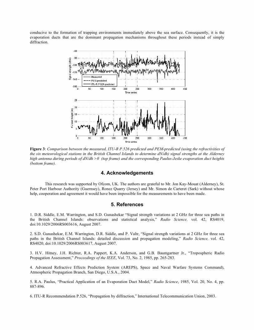
conducive to the formation of trapping environments immediately above the sea surface. Consequently, it is the evaporation ducts that are the dominant propagation mechanisms throughout these periods instead of simply diffraction.
Figure 3: Comparison between the measured, ITU-R P.526 predicted and PEM-predicted (using the refractivities of the six meteorological stations in the British Channel Islands to determine dN/dh) signal strengths at the Alderney high antenna during periods of dN/dh >0 (top frame) and the corresponding Paulus-Jeske evaporation duct heights (bottom frame).
4. Acknowledgements
This research was supported by Ofcom, UK. The authors are grateful to Mr. Jon Kay-Mouat (Alderney), St.
Peter Port Harbour Authority (Guernsey), Ronez Quarry (Jersey) and Mr. Simon de Carteret (Sark) without whose help, cooperation and agreement it would have been impossible for the measurements to have been made.
5. References
1. D.R. Siddle, E.M. Warrington, and S.D. Gunashekar “Signal strength variations at 2 GHz for three sea paths in the British Channel Islands: observations and statistical analysis,” Radio Science, vol. 42, RS4019, doi:10.1029/2006RS003616, August 2007. 2. S.D. Gunashekar, E.M. Warrington, D.R. Siddle, and P. Valtr, “Signal strength variations at 2 GHz for three sea paths in the British Channel Islands: detailed discussion and propagation modeling,” Radio Science, vol. 42, RS4020, doi:10.1029/2006RS003617, August 2007. 3. H.V. Hitney, J.H. Richter, R.A. Pappert, K.A. Anderson, and G.B. Baumgartner Jr., “Tropospheric Radio Propagation Assessment,” Proceedings of the IEEE, Vol. 73, No. 2, 1985, pp. 265-283. 4. Advanced Refractive Effects Prediction System (AREPS), Space and Naval Warfare Systems Command), Atmospheric Propagation Branch, San Diego, U.S.A., 2004. 5. R.A. Paulus, “Practical Application of an Evaporation Duct Model,” Radio Science, 1985, Vol. 20, No. 4, pp. 887-896. 6. ITU-R Recommendation P.526, “Propagation by diffraction,” International Telecommunication Union, 2003.