propagation and antennas - overblogddata.over-blog.com/xxxyyy/0/06/46/58/propagation-an… · ·...
TRANSCRIPT
PROPAGATION AND ANTENNAS
ELECTOMAGNETIC ELECTOMAGNETIC
WAVESWAVES

ELECTROMAGNETIC WAVESELECTROMAGNETIC WAVES
•· A WAVE IS A CARRIER OF ENERGY OR INFORMATION, WHICH IS A FUNCTION OF TIME AND SPACE.
•·MAXWELL PREDICTED THE EXISTENCE OF EM WAVES AND ESTABLISHED IT THROUGH MAXWELL'S EQUATION.
•·EXAMPLES : RADIO, RADAR BEAMS, TV SIGNALS etc.
ELECTROMAGNETIC WAVESELECTROMAGNETIC WAVES
•OSCILLATIONS WHICH PROPAGATE THROUGH FREE SPACE WITH THE VELOCITY OF LIGHT (i.e.3x108 m/s)
•THESE ARE TRANSVERSE WAVES (OSCILLATIONS PERPENDICULAR TO DIRECTION OF PROPAGATION)
•IT HAS ELECTRIC FIELD AND MAGNETIC FIELD WHICH ARE HENCE PERPENDICULAR TO DIRECTION OF PROPAGATION AND ALSO MUTUALLY PERPENDICULAR.

EM WAVES SPREAD UNIFORMLY IN ALL DIRECTIONS IN FREE SPACE FROM A POINT SOURCE.
THE PLANE JOINING ALL THE POINTS OF IDENTICAL PHASE AT A PARTICULAR INSTANT IS CALLED A WAVE FRONT.
IN FREE SPACE, IT IS SPHERICAL.
DEFINITIONSDEFINITIONS
ELECTROMAGNETIC RADIATIONELECTROMAGNETIC RADIATION
POWER ESCAPING INTO SPACE IS SAID TO BE RADIATED & IS GOVERNED BY THE CHARACTERISTICS OF FREE SPACE.
FREE SPACEFREE SPACE
SPACE THAT DOES NOT INTERFERE WITH THE NORMAL RADIATION & PROPAGATION OF RADIO WAVES.
IT DOES NOT HAVE MAGNETIC OR GRAVITATIONAL FIELDS, SOLID BODIES OR IONISED PARTICLES.
•ISOTROPIC SOURCEISOTROPIC SOURCE :- WHICH RADIATES EQUALLY IN ALL DIRECTIONS IN SPACE. •ISOTROPIC MEDIUMISOTROPIC MEDIUM :- IN WHICH VELOCITY OF RADIATION IS CONSTANT AT ALL POINTS (AS IN FREE SPACE). THIS MAKES THE WAVE FRONT SPHERICAL.

WAVES IN FREE SPACEWAVES IN FREE SPACE

Wave front ‘Q’ Wave front ‘P’
Q
P
WAVES IN FREE SPACE

P & Q are the two wave fronts. The power ‘Pt’
at point ‘O’ is transmitted in all directions and
is called isotropic radiation.
The power density of a wave front ‘P’ is
different from the power density of the wave
front ‘Q’
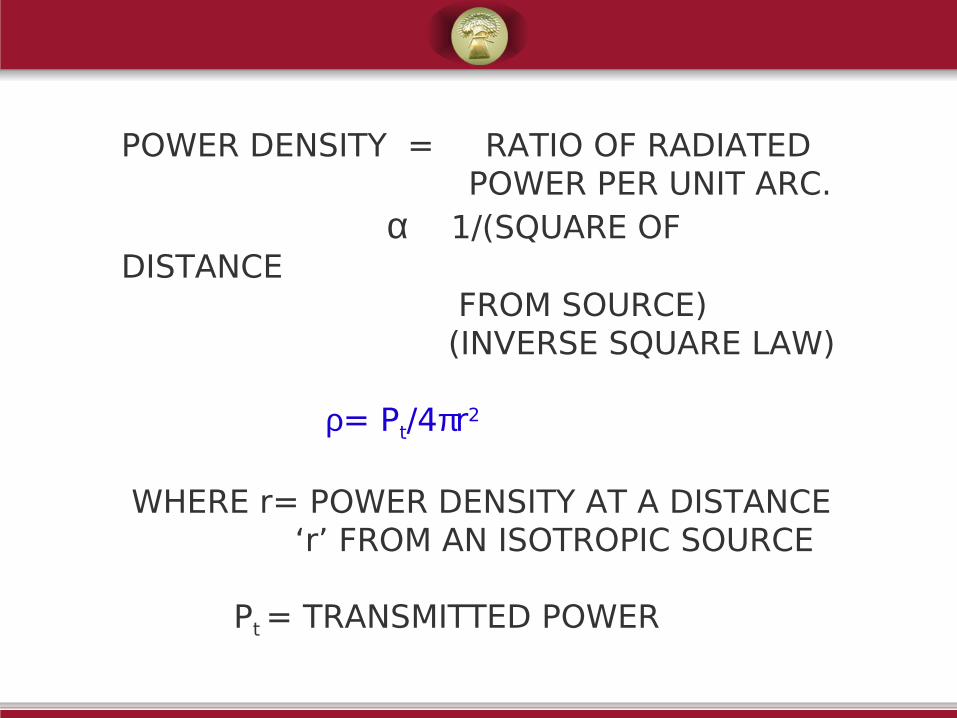
POWER DENSITY = RATIO OF RADIATED POWER PER UNIT ARC. α 1/(SQUARE OF DISTANCE FROM SOURCE) (INVERSE SQUARE LAW)
ρ= Pt/4πr2
WHERE r= POWER DENSITY AT A DISTANCE ‘r’ FROM AN ISOTROPIC SOURCE
Pt = TRANSMITTED POWER

• ELECTRIC FIELD α SQUARE ROOT OF INTENSITY OF AN POWER DENSITY EM WAVE AT THAT POINT.
(SIMILAR TO: VOLTAGE α SQUARE ROOT OF POWER)
•IT MAY BE SHOWN ε = √30 P t VOLTS /m r

•IN ANALOGY TO THE RELATION BETWEEN POWER AND VOLTAGE, IT MAY BE SHOWN ρ = ε 2 z WHERE z = CHARACTERISTIC IMPEDANCE OF FREE SPACE ∴ z = ε 2 = (30 P t) / ( Pt/4πr2 ) ρ r2
or z = 120 π
or z = 377 ohms

APPLICATIONSAPPLICATIONS
• IN ALL COMMUNICATIONS LIKE • POLICE RADIO TV SATELLITE IONOSPHERIC TROPOSPHERIC WIRELESS CELLULAR MOBILE COMMUNICATIONS
IN ALL TYPES OF RADARS LIKE• DOPPLER RADAR• AIRPORT SURVEILLANCE RADAR• WEATHER FORECASTING RADAR• REMOTE SENSING RADAR• GROUND MAPPING RADAR• FIRE CONTROL RADAR ALSO USED IN RADIO THERAPY, MW OVENS etc.
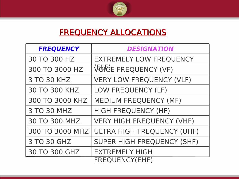
FREQUENCY ALLOCATIONSFREQUENCY ALLOCATIONS
HIGH FREQUENCY (HF) 3 TO 30 MHZ
VERY HIGH FREQUENCY (VHF)30 TO 300 MHZ
ULTRA HIGH FREQUENCY (UHF) 300 TO 3000 MHZ
SUPER HIGH FREQUENCY (SHF) 3 TO 30 GHZ
VOICE FREQUENCY (VF)300 TO 3000 HZ
LOW FREQUENCY (LF)30 TO 300 KHZ
EXTREMELY LOW FREQUENCY (ELF)
30 TO 300 HZ
MEDIUM FREQUENCY (MF) 300 TO 3000 KHZ
VERY LOW FREQUENCY (VLF) 3 TO 30 KHZ
EXTREMELY HIGH FREQUENCY(EHF)
30 TO 300 GHZ
DESIGNATIONFREQUENCY
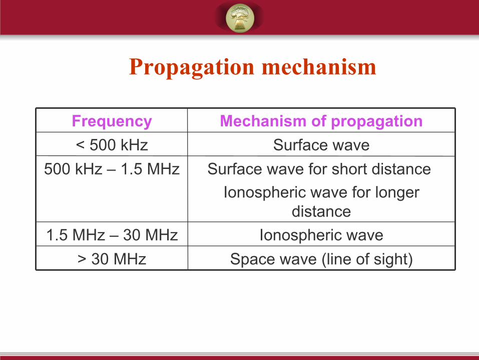
Propagation mechanism
Space wave (line of sight)> 30 MHz
Ionospheric wave1.5 MHz – 30 MHz
Surface wave for short distance
Ionospheric wave for longer distance
500 kHz – 1.5 MHz
Surface wave< 500 kHz
Mechanism of propagationFrequency

Radio frequency bands used in Railways
HF communication (3 MHz-30 MHz band) was once used in Railways; Now obsolete
7 GHz MW,
18 GHz MW
3GHz – 30 GHzSHF (MW)
2 GHz UHF links,
Train radio through leaky coaxial cable
in tunnels,
GSM & GSM-R
300 MHz – 3 GHzUHF
Walkie-talkie30 MHz – 300 MHzVHF
ApplicationBandFrequency range

GSM & GSM-R
921-960 MHz876-915 MHzGSM-R
1930-1990 MHz1850-1910 MHzGSM-1900
1805-1880 MHz1710-1785 MHzGSM-1800
935-960 MHz890-915 MHzGSM-900
Down link
(BTS to MS)
Up link
(MS to BTS)
Type
POLARISATION OF A POLARISATION OF A WAVEWAVE
POLARISATION OF A WAVEPOLARISATION OF A WAVE THE POLARISATION OF A WAVE IS DEFINED AS
THE DIRECTION OF THE ELECTRIC FIELD AT A GIVEN POINT OF TIME
TYPES OF POLARISATION
• LINEAR POLARISATION i) HORIZONTAL POLARISATION ii) VERTICAL POLARISATION iii)THETA POLARISATION
• CIRCULAR POLARISATION
• ELLIPTICAL POLARISATION

A WAVE IS SAID TO BE LINEARELY POLARISED IF THE ELECTRIC FIELD LIES WHOLLY IN ONE PLANE CONTAINING THE DIRECTION OF PROPAGATION.
IF EY=0 AND EX IS PRESENT, WHEN A WAVE TRAVELS IN Z-DIRECTION WITH E-FIELD LYING IN XY-PLANE, IT IS SAID TO BE HORIZONTALLY POLARISED.
IF EX=0 AND EY IS PRESENT, THEN THE WAVE IS VERTICALLY POLARISED.
IF EX AND EY ARE PRESENT AND ARE IN PHASE, THEN THE WAVE IS THETA POLARISED.

FOR HORIZONTALLY POLARISED WAVE, THE ELECTRIC FIELD LIES IN A PLANE PARALLEL TO EARTH’S SURFACE.
ALL THE ELECTRIC INTENSITY VECTORS ARE VERTICAL FOR A VERTICALLY POLARISED WAVE.
THE DIRECTION OF POLARISATION IS SAME AS THE DIRECTION OF ANTENNA.
THUS, VERTICALLY POLARISED WAVE IS RADIATED BY VERTICAL ANTENNA.
HORIZONTALLY POLARISED WAVE IS RADIATED BY HORIZONTAL ANTENNA.

PROPAGATION PROPAGATION CHARACTERISTICS OF EM CHARACTERISTICS OF EM
WAVESWAVES

PROPAGATION CHARACTERISTICS OF EM PROPAGATION CHARACTERISTICS OF EM WAVESWAVES
• THE WAVE PROPAGATION CHARACTERISTICS BETWEEN TRANSMITTER AND RECEIVER ARE CONTROLLED BY
1) TRANSMITTING ANTENNA 2) OPERATING FREQUENCIES 3) MEDIA BETWEEN TX AND RX
• THE EM WAVE RADIATED BY THE TX ANTENNA IS A TRANSVERSE WAVE.

IT MOVES FROM TX TO RX IN THE FOLLOWING WAYS
• A PART OF THE WAVE TRAVELS ALONG OR NEAR THE SURFACE OF THE EARTH. THIS IS THIS IS GROUND WAVE.GROUND WAVE.
2. SOME WAVES NEITHER FOLLOWS THE EARTH, NOR MOVES TOWARD THE SKY, BUT TRAVELS DIRECTLY FROM THE TX TO THE RX ANTENNA. THESE ARE SPACE OR SPACE OR TROPOSPHERIC WAVESTROPOSPHERIC WAVES.
3. SOME WAVES TRAVEL UPWARDS TOWARDS THE SKY AND GET REFLECTED BACK TO THE RECEIVER.
THESE ARE SKY OR IONOSPHERIC WAVESIONOSPHERIC WAVES.

•GROUND WAVESGROUND WAVES ARE USEFUL FOR COMMUNICATION AT VLF, LF & MF RANGES (BROADCAST SIGNALS RECEIVED DURING DAY)
•SPACE WAVESSPACE WAVES ARE USEFUL ABOVE THE FREQUENCY OF 30 MHZ (FM RECEPTION IS NORMALLY BY SPACE WAVE PROPAGATION)
•SKY WAVESSKY WAVES ARE USEFUL FOR FREQUENCIES BETWEEN 2 TO 30 MHZ (RESPONSIBLE FOR LONG DISTANCE COMMUNICATION)
FACTORS INFLUENCING FACTORS INFLUENCING EM WAVE PROPAGATIONEM WAVE PROPAGATION
FACTORS INFLUENCING EM WAVE FACTORS INFLUENCING EM WAVE PROPAGATIONPROPAGATION
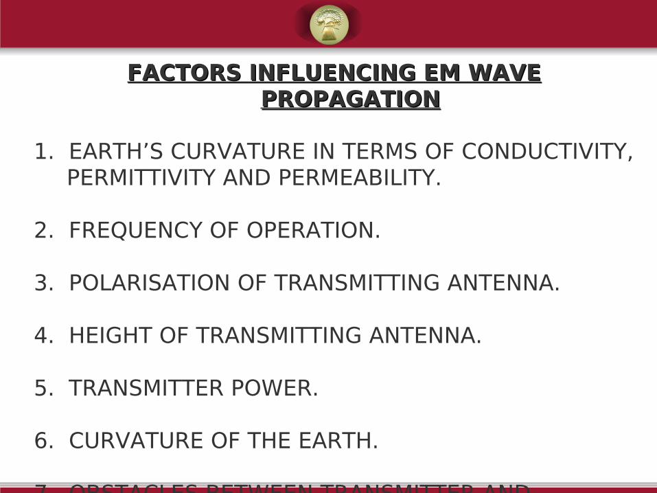
1. EARTH’S CURVATURE IN TERMS OF CONDUCTIVITY, PERMITTIVITY AND PERMEABILITY.
2. FREQUENCY OF OPERATION.
3. POLARISATION OF TRANSMITTING ANTENNA.
4. HEIGHT OF TRANSMITTING ANTENNA.
5. TRANSMITTER POWER.
6. CURVATURE OF THE EARTH.
7. OBSTACLES BETWEEN TRANSMITTER AND RECEIVER.
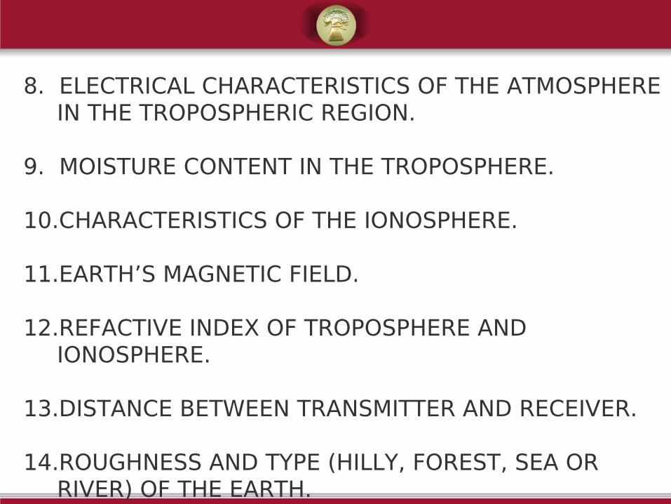
8. ELECTRICAL CHARACTERISTICS OF THE ATMOSPHERE IN THE TROPOSPHERIC REGION.
9. MOISTURE CONTENT IN THE TROPOSPHERE.
10.CHARACTERISTICS OF THE IONOSPHERE.
11.EARTH’S MAGNETIC FIELD.
12.REFACTIVE INDEX OF TROPOSPHERE AND IONOSPHERE.
13.DISTANCE BETWEEN TRANSMITTER AND RECEIVER.
14.ROUGHNESS AND TYPE (HILLY, FOREST, SEA OR RIVER) OF THE EARTH.
GROUND WAVE

GROUND WAVE
• IT PROPAGATES FROM TRANSMITTER TO RECEIVER BY GLIDING OVER THE SURFACE OF THE EARTH.
• IT EXISTS WHEN 1) BOTH TRANSMITTING AND RECEIVING ANTENNAS ARE CLOSE TO THE SURFACE OF THE EARTH. 2) THE ANTENNAS ARE VERTICALLY POLARISED.

•IT IS OF IMPORTANCE AT MF (BROADCAST) AND LF
•IT IS LIMITED TO ONLY A FEW KM.
•FIELD STRENGTH VARIES WITH CHARACTERISTICS
OF THE EARTH AND IS INVERSELY PROPORTIONAL
TO THE SQUARE OF THE DISTANCE AND THE
FREQUENCY
•REQUIRES RELATIVELY HIGH TRANSMITTER POWER.
•NOT AFFECTED BY THE CHANGES IN ATMOSPHERIC CONDITIONS.
•CAN BE USED TO COMMUNICATE BETWEEN SHIP- TO-SHIP, SHIP-TO-SHORE, MARITIME MOBILE COMMUNICATION AND RADIO NAVIGATION.
•HORIZONTALLY POLARISED ANTENNAS ARE NOT PREFFERED, AS THE HORIZONTAL COMPONENT OF THE ELECTRIC FIELD IN CONTACT WITH THE EARTH, IS SHORT CIRCUITED BY THE EARTH.
SKY WAVES SKY WAVES
OR OR
IONOSPHERIC WAVESIONOSPHERIC WAVES

SKY WAVES OR IONOSPHERIC WAVE SKY WAVES OR IONOSPHERIC WAVE PROPAGATIONPROPAGATION
•IT IS THE UPPER PORTION OF THE ATMOSPHERE (BETWEEN APPROX.50KM AND 400KM ABOVE THE EARTH)
•IN THIS REGION, GASES GET IONISED BY ABSORBING LARGE QUANTITIES OF RADIATION AND FORM DIFFERENT LAYERS.
•IONISATION INCREASES WITH ALTITUDE.
•VARIATION IS NOT LINEAR, BUT TENDS TO BE STRATIFIED BY FORMING OF LAYERS.

•The amount of ionization depends upon the rate of formation of the ions and the rate of recombination.
•At lower altitudes since the atmospheric pressure is large the rate of combination is large so that ionization is small.
•At higher altitudes since the atmospheric pressure is low the rate of re-combination is small so that ionization is large.

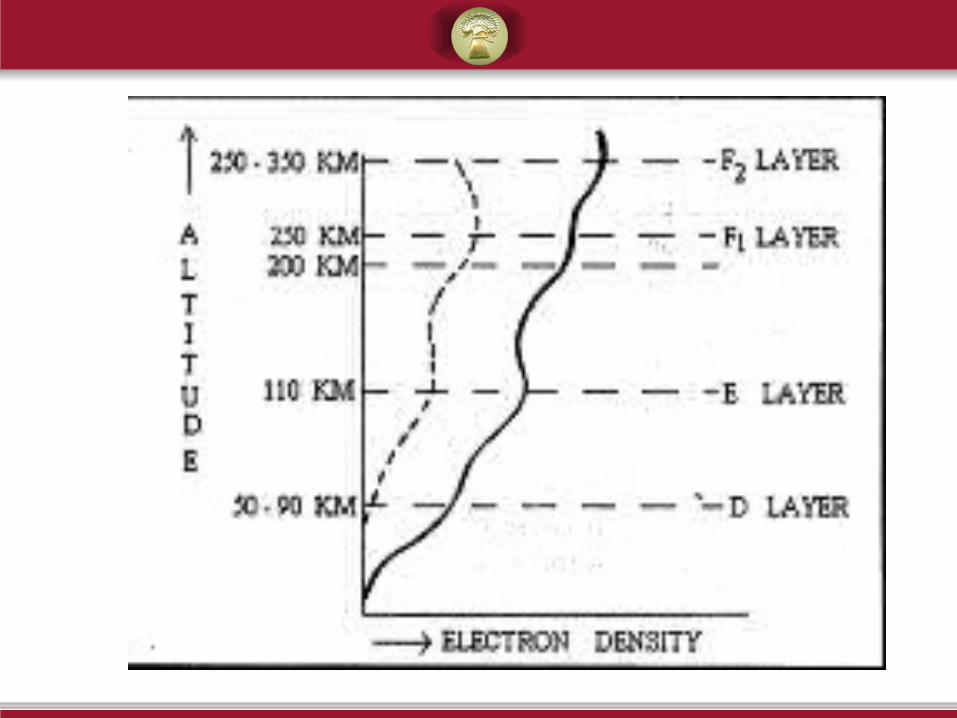
• D- LayerD- Layer 50Km – 90Km above the earth’s
surface. It will disappear at night..
• E- LayerE- Layer 110Km above the earth’s
surface.
• F1 & F2F1 & F2 220Km and 250-350Km
respectively. At night these two layers make
one layer. The ionization of all the layers is
maximum at day time and minimum at night.

0 66 12 18 24
Time (in hrs)
Alt
itu
de
F
E
D
F1
F2
F
50-90 Km
100-120 Km
220 Km
200 Km
250-350 Km
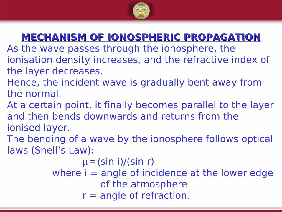
MECHANISM OF IONOSPHERIC PROPAGATIONMECHANISM OF IONOSPHERIC PROPAGATIONAs the wave passes through the ionosphere, the ionisation density increases, and the refractive index of the layer decreases.Hence, the incident wave is gradually bent away from the normal.At a certain point, it finally becomes parallel to the layer and then bends downwards and returns from the ionised layer.The bending of a wave by the ionosphere follows optical laws (Snell’s Law): µ = (sin i)/(sin r) where i = angle of incidence at the lower edge of the atmosphere r = angle of refraction.

CHARACTERISTIC PARAMETERS OF IONOSPHERIC CHARACTERISTIC PARAMETERS OF IONOSPHERIC PROPAGATIONPROPAGATION
• Virtual height : It is defined as the height that is reached by a short pulse of energy which has the same time delay original wave. Virtual height of a layer is always greater than actual height.
Virtual heightActual
height
Ionospheric Layer

2.2. Critical FrequencyCritical Frequency : Fc for a given layer is defined as the highest frequency that will be reflected to earth by that layer at vertical incidence.
It is the limiting frequency below which a wave is reflected and above which it penetrates through an ionospheric layer at normal incidence.
Refractive Index, by definition, is equal to square root of dielectric constant, i.e.
µ = εr
i.e (sin i)/(sin r) = 1- (81N/F2)
Here N = Electron Density
F = Frequency in KHz

For the wave to be reflected back, r=900
i.e. sin i = 1- (81N/F2)
or, sin2 i = 1- (81N/F2)
or, 1- sin2 i = 81N/F2
or, cos2i = 81N/F2
or, F = ( 81N)/cos i
= 9( N)/cos i
= 9( N) sec i
If i=00, then
F= 9 N = FC
This is the critical frequency.

Above this frequency, the wave will not be reflected back to earth.
At any other angle, the frequency which will be capable of being reflected back will be
This is referred to as the SECANT RULESECANT RULE and gives the MAXIMUM USABLE FREQUENCYMAXIMUM USABLE FREQUENCY at various angles of incidence.
MAXIMUM USABLE FREQUENCYMAXIMUM USABLE FREQUENCY : It is the highest frequency of wave that is reflected by the layer at an angle of incidence other than normal.
F = FC sec i

SKIP DISTANCESKIP DISTANCE: It is the shortest distance from the transmitter that is covered by a fixed frequency ( FC)
Large angle of incidence Ray returns to ground at a long distance from TX.
Angle of incidence reduced Ray returns to ground at a shorter distance.
Ultimately, possibility of a certain distance not being covered exists, since ray escapes.
SKIP DISTANCE
SKIP FREQUENCYSKIP FREQUENCY::
It is the maximum frequency above which it is not possible for a signal to reach a point via Ionospheric Reflection.
OPTIMUM WORKING FREQUENCY (OWF):OPTIMUM WORKING FREQUENCY (OWF):
•The frequency of wave which is normally used for ionospheric communication is known as OWF.
•It is generally chosen to be about 15% less than the MUF.
•It is always desirable to use as high a frequency as possible (but not too near the skip frequency or MUF), since any slight variation in the ionosphere condition may cause a loss of signal.

SPACE WAVE SPACE WAVE
OR OR
TROPOSPHERIC WAVETROPOSPHERIC WAVE

SPACE WAVE OR TROPOSPHERIC WAVE SPACE WAVE OR TROPOSPHERIC WAVE PROPAGATIONPROPAGATION
Troposphere is the region of atmosphere within 16 Km above the surface of the earth.
The EM wave that propagates from the transmitter to the receiver in the earth’s troposphere is called Space Wave or Tropospheric Wave.
Space Wave propagation is useful at frequencies above 30MHz.
It is useful for FM, TV and Radar applications.
It is also used in VHF, UHF and higher frequency bands.

The space wave field strength is affected by
2.2. Curvature of the earth:Curvature of the earth:
The field strength at the receiver becomes small as the direct ray may not reach the receiving antenna. The ground reflected rays diverge after their incidence on the earth.
The curvature of the earth creates shadow zonesshadow zones, also called diffraction zones. These are the regions where no signal reaches.
Reduces the possible distance of communication.
Field strength available at receiver becomes small.
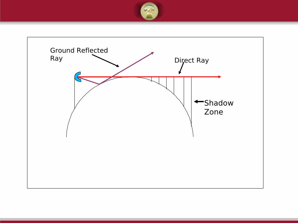
Shadow Zone
Direct Ray
Ground Reflected Ray
2. Effect of Earth’s Imperfections and 2. Effect of Earth’s Imperfections and RoughnessRoughness
Earth is basically imperfect and rough
For perfect earth, reflection coefficient is unity. But actual earth makes it different.
For reflection from perfect earth, phase change is 1800. But actual earth makes it different.
Amplitude of ground reflected ray is smaller than that of Direct ray.
The field strength at receiver is reduced due to the roughness.

3.Effect Of Hills, Buildings and Other ObstaclesEffect Of Hills, Buildings and Other Obstacles
These create Shadow Zones.
Hence possible distance of transmission is reduced.
4.4. Height Above Earth Height Above Earth
Field varies with height above earth.
Field variation is characterised by maxima, minima and nulls
Maximas,minimas depend on frequency, height of transmitting antenna, ground characteristics and polarisation of the wave.
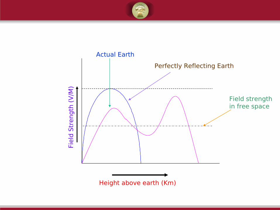
Height above earth (Km)
Field
Str
ength
(V
/M)
Actual Earth
Perfectly Reflecting Earth
Field strength in free space

5.Transition between Ground Wave and Space Transition between Ground Wave and Space WaveWave
When the transmitting antenna is close to earth, Ground Wave exists and the field strength is independent of height of antenna.
Antenna height has an effect on field strength, which depends upon frequency, polarisation and constants of earth.
At higher heights, Space Wave dominates.

Atmospheric Effects in Space Wave Atmospheric Effects in Space Wave PropagationPropagation
Atmosphere consists of gas molecules and water vapour.
So, density is higher compared to free space.
For standard atmosphere; Pressure, Temperature, Humidity decrease linearly with altitude.
Thus Refractive Index of air depends upon height.
This gives rise to phenomenon like
Reflection
Refraction
Scattering
Fading, etc.

REFLECTIONREFLECTION
Occurs when waves strike smooth surface, such as water, smooth earth, etc.
Both Reflected and Direct wave reaching the receiver ensures reduced signal strength.
These may arrive either in phase, or out of phase, or partially out of phase.
For perfectly smooth surface, and under condition of amplitude being equal and exactly out of phase at receiver, the received wave may get completely cut cut offoff.
This is FADINGFADING.
Hence care should be taken during survey that there are no good reflectors in the path.

DIFFRACTIONDIFFRACTION
Obstacle (like tall buildings or hill tops) in the path of the wave, increases transmission loss.
Wave arrives at the receiver by the process of diffraction.

REFRACTIONREFRACTION
Due to the varying refractive indices with height, the wave does not follow a straight path from Transmitting to Receiving antennas.
It follows a bent path, i.e. follows the curvature of the earth.
Hence radius of the earth seems to be larger Hence radius of the earth seems to be larger than actual for the beamthan actual for the beam.
Also the path varies during various hours of day and at various place.

K-FACTORK-FACTOR

K-FactorK-Factor
To correlate between earth’s curvature and the curvature of the MW beam path, it is customary to take one of the curvatures to be a straight line (generally MW beam).
Due to this assumption, the actual curvature of the beam will also have to be modified to keep the
earlier correlation same.
The modification of earth’s curvature is done by multiplying actual earth’s curvature by K-Factor.K-Factor.
K-Factor depends upon atmospheric conditions.
Hence, Modified earth’s curvature also changes with atmospheric conditions.

The amount and direction of bending subjected by the MW beam is defined
either by the Refractive Index Gradient dN/dh (where N is the Radio Refractivity and h is the height of the layer above the surface of the earth)
or very often by the Effective Earth’s Radius Factor K.
Definition
K is a factor which when multiplied by the actual earth’s radius, gives the value of the modified earth’s radius employed in profile chart to make the MW beam a straight line.

It can be Shown that
K-Factor= 157/(157+dN/dh)
Here, N (Radio Refractivity) = 77.6(P/T)+3.73x105(e/T2)
Where, P = Total Atmospheric Pressure in Millibar
T = Absolute Temperature in 0Kelvin.
e = Water Vapour Pressure in Millibar.

CONDITIONSCONDITIONS
2. When dN/dh = -40 UNITS/Km; K = 4/3 (This is Standard Atmospheric Condition)
3. When dN/dh = -157 UNITS/Km; K = infinity.(This is Super Refractive Atmospheric Condition)
4. When dN/dh = 0 UNITS/Km; K = 1 (This is Sub Refractive Atmospheric Condition)
5. When dN/dh = +79 UNITS/Km; K = 2/3 (This is Sub Refractive Atmospheric Condition)
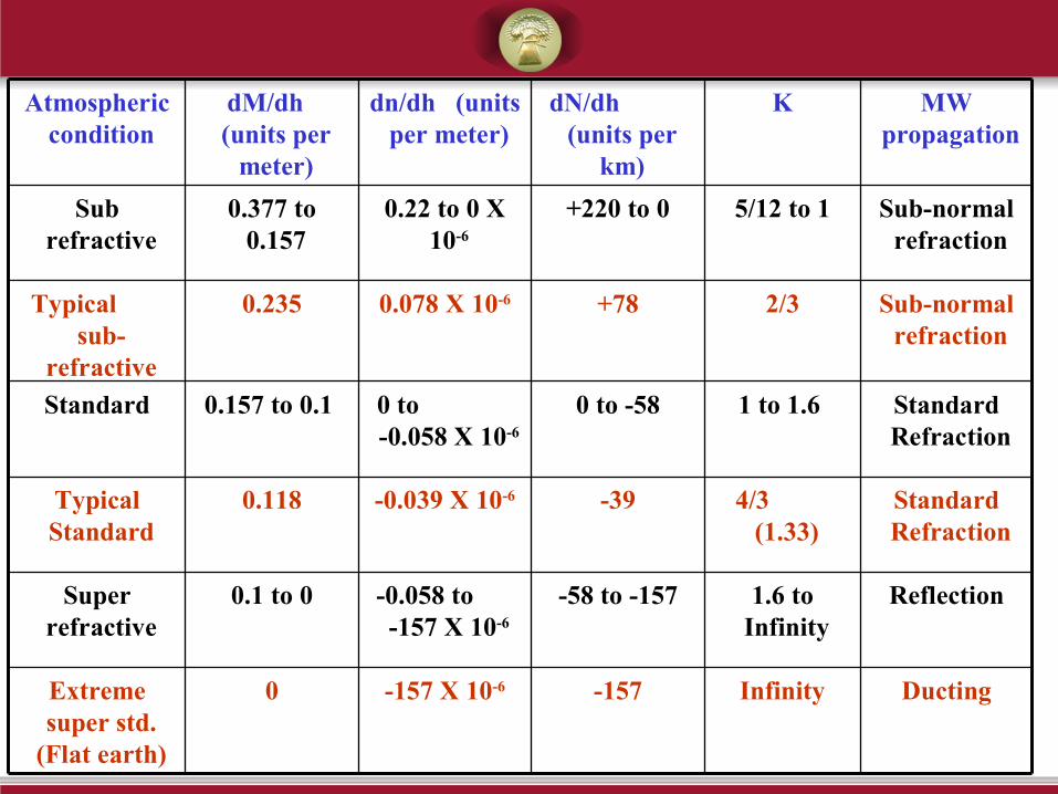
DuctingInfinity-157-157 X 10-60Extreme super std.
(Flat earth)
Reflection1.6 to Infinity
-58 to -157-0.058 to -157 X 10-6
0.1 to 0Super refractive
Standard Refraction
4/3 (1.33)
-39-0.039 X 10-60.118Typical Standard
Standard Refraction
1 to 1.6 0 to -580 to -0.058 X 10⁻⁶
0.157 to 0.1 Standard
Sub-normal refraction
2/3+780.078 X 10-60.235Typical sub-
refractive
Sub-normal refraction
5/12 to 1+220 to 00.22 to 0 X 10-6
0.377 to 0.157
Sub refractive
MW propagation
KdN/dh (units per
km)
dn/dh (units per meter)
dM/dh (units per
meter)
Atmospheric condition

Change in the value of K from 1 to infinity have less influence upon the received signal (excepting multipath fading).
For K<1, the path is vulnerable to extreme multipath fading.
For K= -ve, path is susceptible to blackout fading.

•n is Atmospheric Refractive Index . Variation of ‘n’ w.r.t. height is low i.e. of the order 1010 -6-6 per per metermeter. Hence, we consider certain scaled parameters.
•dN/dh = 1000. dn/dhdN/dh = 1000. dn/dh i.e. N parameter variation gives variation of RI per km. We can use convenient ranges of integer-values for dN/dh corresponding to normal, sub-normal & super-normal conditions of atmosphere.
•M Vs. h graph gives convenient graphical representation of normal, sub-normal & super-normal conditions of atmosphere. Since M = (n-1) 106 + 0.157 h , we have interpolated curvature of earth into M . Hence, M vs.h plot gives modified M vs.h plot gives modified RI profile. RI profile.
•K is ‘Effective earth radius factor’ i.e. factor to interpolate the curvature of propagation (of MW beam) also into base line of path-chart so that we represent earth curvature a well as beam curvature
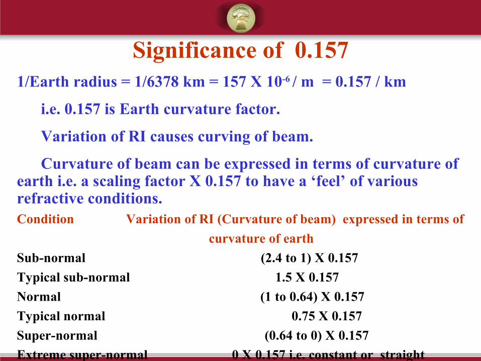
Significance of 0.1571/Earth radius = 1/6378 km = 157 X 10-6 / m = 0.157 / km
i.e. 0.157 is Earth curvature factor.
Variation of RI causes curving of beam.
Curvature of beam can be expressed in terms of curvature of earth i.e. a scaling factor X 0.157 to have a ‘feel’ of various refractive conditions.Condition Variation of RI (Curvature of beam) expressed in terms of
curvature of earth
Sub-normal (2.4 to 1) X 0.157
Typical sub-normal 1.5 X 0.157
Normal (1 to 0.64) X 0.157
Typical normal 0.75 X 0.157
Super-normal (0.64 to 0) X 0.157
Extreme super-normal 0 X 0.157 i.e. constant or straight profile

Super Standard RefractionSuper Standard Refraction
Arises due to reduction in atmospheric density with increased height.
K increases– Results in flattening of the effective Earth’s curvature.
Condition causing it– Passage of cool air over warm body of water.
Atmospheric density increases near the surface (due to low temperature & high humidity).
High downward bending of wave is caused.
In moderate conditions, K infinity, and wave is propagated parallel to earth.
In extreme cases, K=-ve and causes a blackout fade.

SUB - STANDARD REFRACTIONSUB - STANDARD REFRACTION
Arises due to increase in atmospheric density with height.
Condition causing it– When fog is formed with the passage of warm air over cool air or moist surface.
Causes upward bending of beam (Earth’s bulge).K= infinity
K=4/3
K=2/3
K=1

Earth appears to be increasingly flat as the value of of Earth appears to be increasingly flat as the value of of K increases.K increases.
For K=infinity, the earth appears to be perfectly flat for the MW beam, since the beam curves at the same rate as earth.
The curvature for various values of K can be calculated by
h=d1d2/(12.75K) where, h= Change in vertical distance from a horizontal reference line.
d1= Distance from a point to one end of the path (in Km)
d2= Distance from same point to other end of the path (in Km)

How to plot path profilesHow to plot path profilesIdeally, we have to plot the path taken by the rays for normal , sub-normal & super-normal conditions.
If we plot the path profile (using details obtained from Survey maps) on plain graph paper, curvature of Earth is not accounted for.
Hence, for convenience of analysis , bending of radio path to be interpolated in earth curvature for all conditions (normal , sub-normal & super-normal ) and using such curved-abscissa graph sheets, path profiles to be plotted
Hence, we have to find effective earth radius before plotting radio path on profile-chart

Profile Charts Profile charts for various values of K available
Bend of radio path ‘transferred’ to earth radius as per value of K
Mark the terrain specific details from Survey maps on these charts
Mark the tower / antenna
Check for clearances
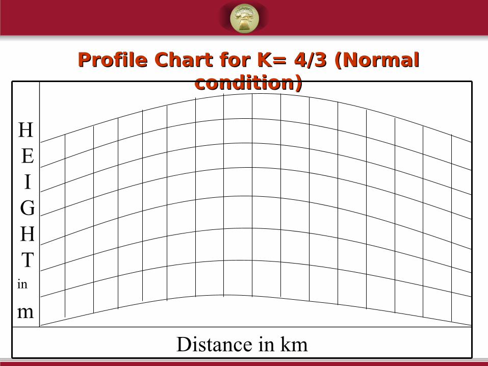
Profile Chart for K= 4/3 (Normal Profile Chart for K= 4/3 (Normal condition)condition)
Distance in km
HEIGHT
in
m
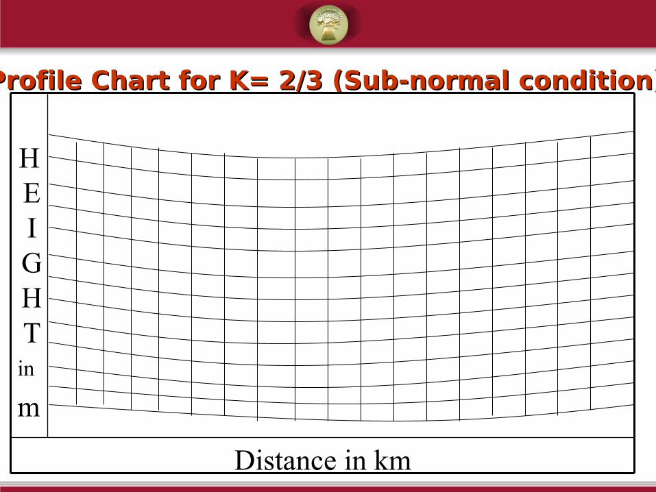
Profile Chart for K= 2/3 (Sub-normal condition)Profile Chart for K= 2/3 (Sub-normal condition)
Distance in km
HEIGHT
in
m

Profile Chart for K= Infinity Profile Chart for K= Infinity (Super-normal condition)(Super-normal condition)
Distance in km
H E I GHTinM

M-PROFILES
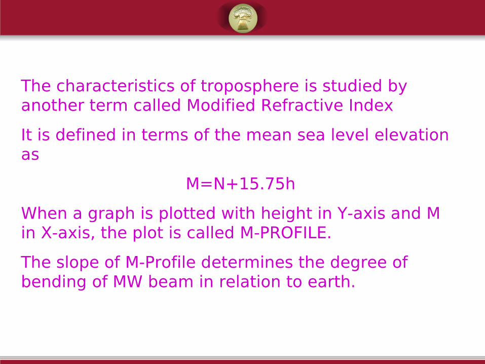
The characteristics of troposphere is studied by another term called Modified Refractive Index
It is defined in terms of the mean sea level elevation as
M=N+15.75h
When a graph is plotted with height in Y-axis and M in X-axis, the plot is called M-PROFILE.
The slope of M-Profile determines the degree of bending of MW beam in relation to earth.
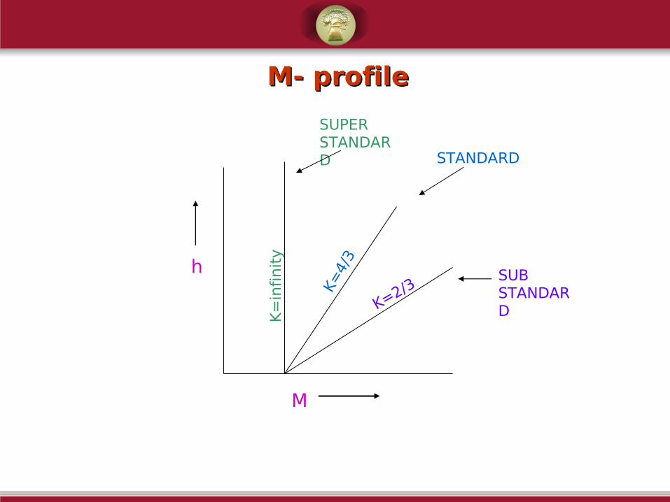
M- profileM- profile
M
hK
=in
finit
y
K=4/
3
K=2/3
STANDARD
SUPER STANDARD
SUB STANDARD

M-profile : Sub-normal conditionM-profile : Sub-normal condition
M
h
dM/dh = 0.235 per meter at the heights under consideration
At higher values of h, dM/dh reaches normal profile

M- profile : Super-normal conditionM- profile : Super-normal condition
dM/dh 0.1 to 1 at heights of consideration
At higher values of h, dM/dh reaches normal profile
M
h
h

Super-normal condition with ground-based ductSuper-normal condition with ground-based duct
Extreme case of super-standard condition, when there is temperature inversion
Signal gets trapped in the duct and may cause over-reach problems
h
M

Super-normal condition with elevated Super-normal condition with elevated ductduct
Duct not close to ground, but elevated
Signal gets trapped in duct in atmosphere
M
h
Essential clearances for Radio Essential clearances for Radio pathpath
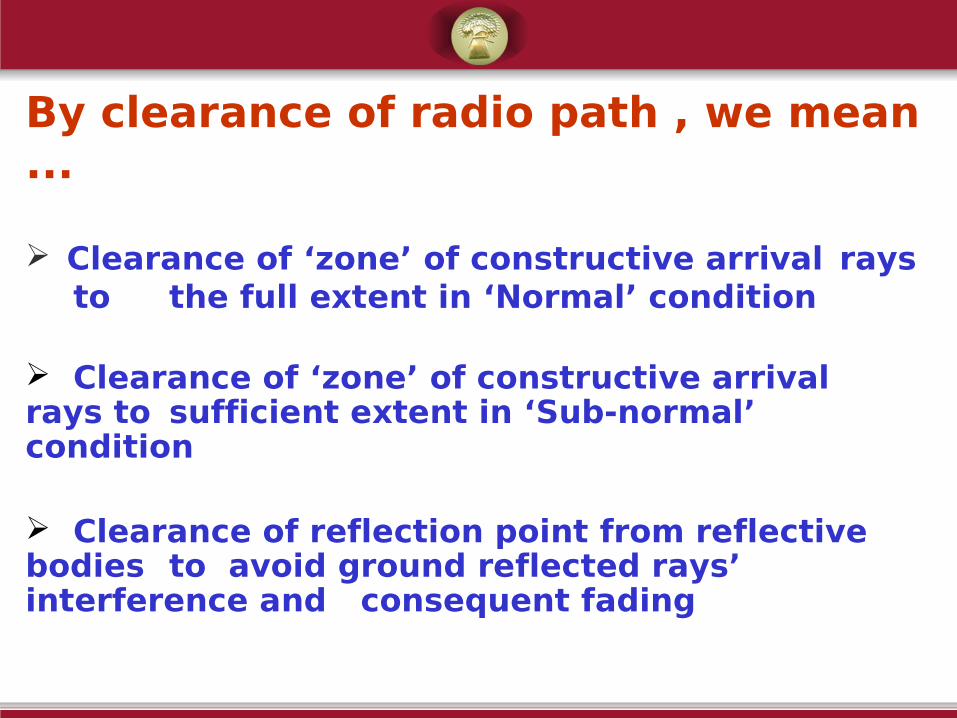
By clearance of radio path , we mean ...
Clearance of ‘zone’ of constructive arrival rays to the full extent in ‘Normal’ condition
Clearance of ‘zone’ of constructive arrival rays to sufficient extent in ‘Sub-normal’ condition
Clearance of reflection point from reflective bodies to avoid ground reflected rays’ interference and consequent fading

Clearance in ‘Normal’ & ‘Sub-normal’ Clearance in ‘Normal’ & ‘Sub-normal’ conditionsconditionsClearance of ‘zone’ of constructive arrival rays
to the required extent –
•Zone of constructive arrival means ‘ First Fresnel Zone’
•For normal condition, take typical value K = 4/3
•For sub-normal condition, take typical value K = 2/3
Let us understand Fresnel Zone & computation of it’s
radius at desired location in the path

Concept of ‘Fresnel Zone’Concept of ‘Fresnel Zone’When MW beam is transmitted from an antenna, the beam gradually spreads conically (Huygen’s Principle).
The total MW energy reaching antenna B is the sum of the energies passing through various zones called FRESNEL’S ZONES.
Maximum energy (primary energy) is concentrated in the central zone, called FIRST FRESNEL’S ZONE.
AB
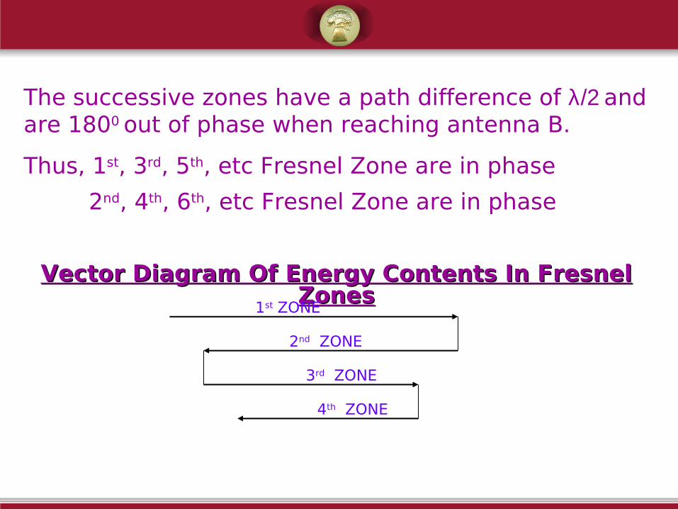
The successive zones have a path difference of λ/2 and are 1800 out of phase when reaching antenna B.
Thus, 1st, 3rd, 5th, etc Fresnel Zone are in phase
2nd, 4th, 6th, etc Fresnel Zone are in phase
Vector Diagram Of Energy Contents In Fresnel Vector Diagram Of Energy Contents In Fresnel ZonesZones
1st ZONE
2nd ZONE
3rd ZONE
4th ZONE
Thus we see that the energies are getting diminished with the higher Fresnel Zones.
The transmitted MW will have maximum energy if only the 1only the 1 stst Fresnel Zone is cleared. Fresnel Zone is cleared.
The strength of the MW signal reaching B will depend upon the no. of Fresnel Zone cleared. (More Fresnel More Fresnel Zone, less strength of signalZone, less strength of signal).
Practically, it is not possible to make an antenna receive only the 1st Fresnel Zone.
So, we limit the the height of TX and RX antenna so that the 2nd Fresnel Zone is obstructed on the lower side at a certain lower value of K.
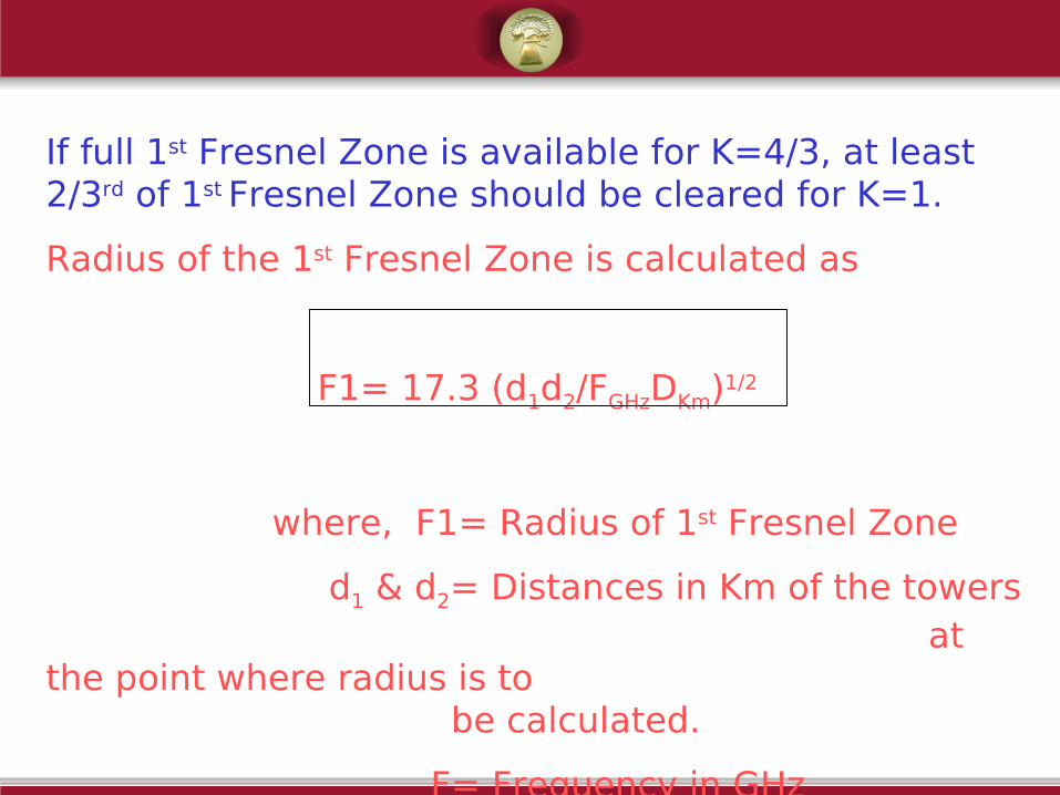
If full 1st Fresnel Zone is available for K=4/3, at least 2/3rd of 1st Fresnel Zone should be cleared for K=1.
Radius of the 1st Fresnel Zone is calculated as
F1= 17.3 (d1d2/FGHzDKm)1/2
where, F1= Radius of 1st Fresnel Zone
d1 & d2= Distances in Km of the towers at the point where radius is to
be calculated.
F= Frequency in GHz
D= Hop distance in Km.

Radius of nth Fresnel zone
Fn = F1 (n)1/2
where, n is the no. of Fresnel Zone for which radius is to be calculated.
While clearing the 1st Fresnel Zone, some tolerance should be given for future obstructions.
This tolerance depends upon the K-Factor
• For K=4/3, full 1st Fresnel Zone+ 10m extra clearance
• For K=1, 2/3rd of 1st Fresnel Zone+ 10m extra clearance
• For K=2/3, grazing clearance of 2/3rd of 1st Fresnel Zone only

FadingFading
It is the change in signal strength at the receiver.
Causes of Signal Loss can be classified into 2 categories
4. Atmospheric conditions related causes
5. Radio path related causes
Atmospheric condition related causesAtmospheric condition related causes
•Attenuation due to rain
–When wavelength is close to rain drop size
–15 G Hz and above , 1 to 10 db per km as per precipitation rate of rain fall
–Below 15 G Hz, attenuation is less than 1 db
•Attenuation due to cloud & fog
–Drop sizes are smaller than rain drop
–Attenuation is more for 15 G HZ and above
•Attenuation due to hail & snow
–Similar to the case of rain

Radio path related causesRadio path related causes•Insufficient path clearances
–Rays getting obstructed by high-rise objects / geographic features
•Multi-path propagation
–Destructive interference of rays reaching on different paths through atmosphere
•Fading due to ground reflection
–Ground reflected signal of significant strength causes fading due to interference with normal path signals
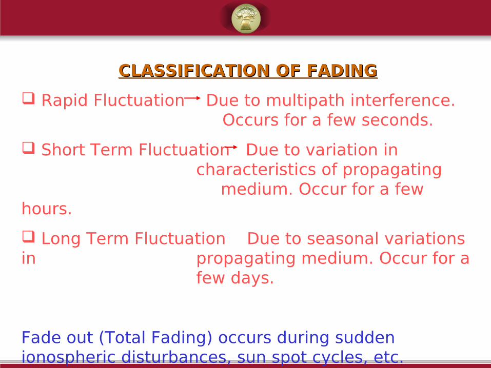
CLASSIFICATION OF FADINGCLASSIFICATION OF FADING
Rapid Fluctuation Due to multipath interference. Occurs for a few seconds.
Short Term Fluctuation Due to variation in characteristics of propagating
medium. Occur for a few hours.
Long Term Fluctuation Due to seasonal variations in propagating medium. Occur for a
few days.
Fade out (Total Fading) occurs during sudden ionospheric disturbances, sun spot cycles, etc.
TYPES OF FADINGTYPES OF FADING
• Frequency - Selective Fading: -
Alternate points of maximum (reinforcement) and minimum(cancellation) signal strength are encountered during space wave propagation from Tx to RX.
This phenomenon is called selective fading.
All terrestrial MW radio systems can suffer from multi-path propagation, where the Rx antenna receives not only the direct signal but also secondary signal which is slightly delayed relative to the direct beams, and bends due to the varying refractive index of the air.
The degree of multi-path fading is heavily dependent on the Hop length, weather condition and water path.

Flat fadingFlat fading
As its name implies is a non frequency dependent attenuation of the input signal at the receiver and typically occurs during periods of heavy rain particularly at higher MW frequency
Difficult to control short term and long term fluctuations.
But fading due to rapid fluctuations can be reduced by different Diversity Techniques.
i. Frequency Diversity
ii. Space Diversity
iii. Polarity Diversity
iv. Time Diversity
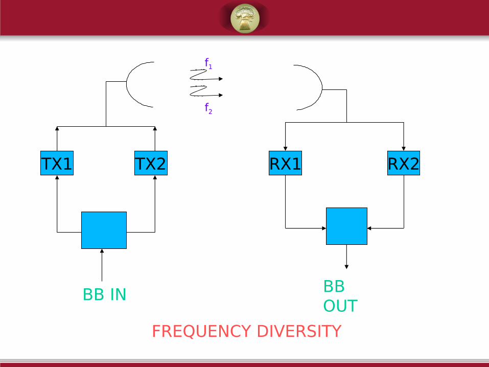
TX1 TX2 RX1 RX2
FREQUENCY DIVERSITY
f1
f2
BB IN BB OUT
FREQUENCY DIVERSITYFREQUENCY DIVERSITY
ADVANTAGES
5. Reliability is more6. Equivalent to 100% hot stand by, hence no need of
providing stand by TX or RX.
DISADVANTAGES
10.Two frequencies are needed11.Improvement by diversity is not much, since 5%
separation of frequency is rarely achieved.

TX RX1 RX2
SPACE DIVERSITY
f1
f1
BB IN
BB OUT
SPACE DIVERSITY
ADVANTAGES
5. One frequency is used.6. Propagation reliability is improved.7. For more vertical separation of antennas, improvement factor
can be more.
DISADVANTAGES
• The two antennas are kept on the same tower.The lower antenna should be in Line of Sight with the TX antenna. Hence length of tower may increase beyond 100m. SPACE DIVERSITY
• Costly• Good tower foundation necessary, since wind pressure will be
large.• Equipment reliability decreased, hence stand by required.
FREQUENCY ALLOCATIONS

Indian Railways have been allotted a frequency band of 7125 MHz to 7425 MHz (4.21 cms - 4.04 cms wavelengths) in the Xc band. (The band of frequency from 7250 - 7300 MHz is restricted in view of satellite to earth allotment).
The spot frequencies permitted in the band for operation of a transmitter (and Receiver) are governed by CCIR Recommendation 385 - 1 which inter - alia stipulates as follows:-fo = Centre frequency = 7275 MHzfn = Channel frequency in MHz in lower half of the bandf1
n = Channel frequency in MHz in Upper half of the band.

then the frequencies (MHz) of the individual channels are expressed by the following relationships:-
Lower half of band fn = fo - 154 + 7n
Upper half of band f’n = fo + 7 + 7n
where n = 1, 2, 3, etc., 1 .........upto 20.
e.g., f1 = 7128 MHz & f’1 = 7289 MHz
f2 =7135 MHz & f’2 =7296 MHz and so on.
2) In section over which the international conduction is arranged all the 'go' channels should be in one half of the band and all the 'return' channels in the other half of the band.
3) When systems with 300 telephone channels are operated in a radio frequency band, channel combination, which result in differences between channel frequencies of less than 14 MHz, should in general be avoided. If sufficient antenna discrimination is available, this precaution may be disregarded.

FREQUENCY PLAN

There are two distinct patterns of frequency plans employed on the Railways. They are the 'Four Frequency' and the 'Two Frequency' plans.
Allocation of frequencies in a four frequency plan is as shown in the figure.

ANTENNASANTENNAS
ANTENNASANTENNASAn antenna is basically a transducer.
It converts RF electrical current into an EM Wave of the same frequency.
It forms a part of the transmitter as well as the receiver circuit.
It is also an impedance matching device. It matches/couples the transmitter and free space or free space and receiver.
The sample antenna is called a Half Wave Length Dipole.
The shortest length of dipole capable of resonance is an electrical half wave length.

Center impedance of a simple dipole ~ 72 ohms (at
resonant frequency)
It increases as we go away from the center.
The antenna impedance is required to be matched
with the characteristic impedance of the feeder line so
that maximum power transfer may take place.
Isotropic antenna: Radiates equal power in all directions.
Actual antenna: Does not radiates power equally in all
directions.

Length of AntennaLength of AntennaPractical antennas have length 5% less than theoretical antennas.
This is because
1.Theoretical length is true when antennas are in free space.
2.For practical antennas, END EFFECT has to be considered, which is caused by
a.Capacitance between pole and antenna
b.Capacitance antenna and earth
c.Inductive effect in the tightening material of antenna
These effects cause the 5% reduction in length.
The practical length of a half wave dipole is
Lm=(142.5/FMHz) meters

VHF
–For fixed stations : Dipoles for omni-bus
–For fixed stations : Yagi for directional
–For mobile sets : Whip antennas
UHF
For fixed stations : Yagi, Grid
For mobile sets (Train radio) : Whip antennas
For GSM – BTS : Sectorized antenna
For GSM Mobile sets :
•MW
–Parabolic antenna (Dish antenna)
–Beam reflectors
–Passive reflectors
How to improve gain of dipole
Add parasitic elements (Director,Reflector)
Parasitic elements reduce impedance below 73 Ohms. Hence use either Shunt feed or Folded dipole

Shunt-fed Yagi antenna
Shunt-fed Yagi features
Length of dipole : 0.48 l
Length of director :0.46l
Length of reflector : 0.5 l
Separation between dipole & director : 0.1 l
Separation between dipole & reflector : 0.16 l
Gain : 6 db
Shunt-feed
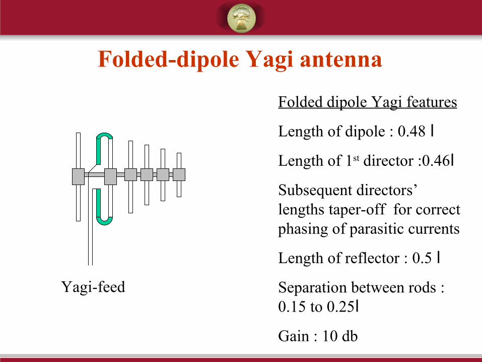
Folded-dipole Yagi antenna
Folded dipole Yagi features
Length of dipole : 0.48 l
Length of 1st director :0.46l
Subsequent directors’ lengths taper-off for correct phasing of parasitic currents
Length of reflector : 0.5 l
Separation between rods : 0.15 to 0.25l
Gain : 10 db
Yagi-feed
Transmitting and receiving antennas for use in the UHF (.3 – 3GHz) and MW (1- 100GHz) regions tend to be directive.The dimensions of an antenna must generally be several wavelengths in order for it to have high gain. At the high frequencies , antennas need not be physically large to have multiple wavelength dimensions. For UHF and MW frequencies the following antennas are used: -
2. The Yagi-Udi Antennas.
3. Grid Pack or Grid Antennas.
4. Normal Parabolic antenna

Reflector
Director
Driven element
.55λ .45λ
λ / 10 λ / 10
Yagi
Grid

The Yagi(Yagi-Uda) antenna is an array consisting of a driven element and one or more parasitic elements(Director ,Reflector). They are arranged collinearly and close together to increase directivity.

Grid Antenna: - A grid antenna employs welded tube which can be split into section for ease transportation and handling
GRIDPAK ANTENNA

Gain of Parabolic antenna (7 GHz band)
46 db3.3 m dia metal antenna
45 db3 m dia metal antenna
43 db2.4 m dia metal antenna
17 db(Formula not applicable)
Fiber antenna
Gain of antenna
6 (D/l)2
Antenna type

Front to back ratio of a antenna: Ratio of the front Lobe power to back lobe power.
Half power beam width: It is the nominal total angular width of the main beam at the 3dB points. In the fig. the angle represents the beam- width.The beam width is given by Φ = 22/ FB in degree; F = Frequency in GHz and B = Diameter of antenna in meters
900
1800
-450
1350 -1350
450
00
Major front Lobe
3dB
Φ
Half power beam width
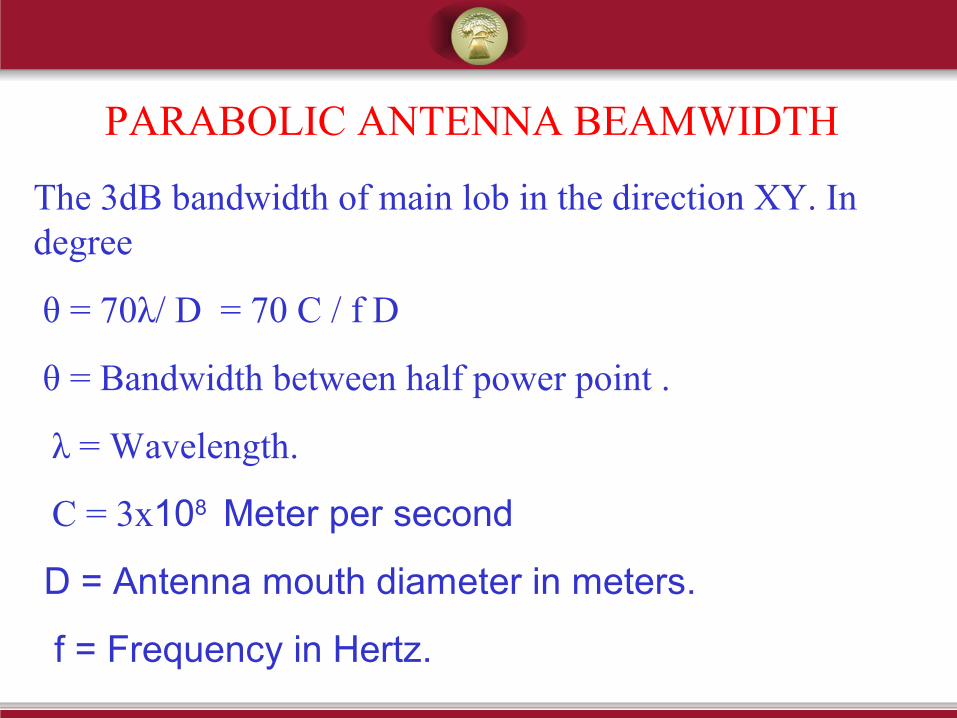
PARABOLIC ANTENNA BEAMWIDTH
The 3dB bandwidth of main lob in the direction XY. In degree
θ = 70λ/ D = 70 C / f D
θ = Bandwidth between half power point .
λ = Wavelength.
C = 3x10⁸ Meter per second
D = Antenna mouth diameter in meters.
f = Frequency in Hertz.
PASSIVE REFLECTOR
The simplest and most common reflector system consists
of a parabolic, antenna mounted at ground level and
directed technically to illuminate a passive reflector at
the top of a tower . This reflector , inclined at 45deg.
redirects the beam horizontally to a distance site,where a
similar Periscope system may be used to reflect the signal
back to ground level.

PASSIVE REPEATERS
Sometimes a tower cannot provide clearance over an
obstruction . When the line of sight of MW is obstructed by
mountains or any other substances the Passive repeaters may
be used to merely change the path direction without
amplification
The Bill Board, a large , flat surface which is simply as a
reflector is used as a repeater. Untypical a system, a bill
board repeater might be located at a turn in a valley,
effectively bending the beam to follow the valley

Ground plane Antenna(GP): -
GP antenna is used for HF and VHF communication. The basic design is quarter wavelength vertical antenna with four Radials Mounted at the antenna base. The radials may be made of tubes or wire.The Coaxial line from the transmitter of 50Ώ characteristic impedance is connected to the GP antenna.
Radiator
Radials
Co axial line
GP ANTENNA
