projectlatestfinal
TRANSCRIPT

Regenerative Braking Using Spiral Torsion Spring
Submitted by:
Pulkit Sharma (BE/10261/2012)Aditya Sanjay Patil (BE/10001/2012)
Anant Bhardwaj (BE/10235/2012)Achyut Nair (BE/10330/2012)
May 6, 2016
ME8002: Project report at the end of 8th Semester
Supervised by Arun Dayal Udai.
Department of Mechanical EngineeringBirla Institute of Technology, Mesra
Ranchi - 835215

2
Acknowledgement of Sources
For all ideas taken from other sources (books, articles, internet), the source of theideas is mentioned in the main text and fully referenced at the end of the report.
All material which is quoted essentially word-for-word from other sources isgiven in quotation marks and referenced.
Pictures and diagrams copied from the internet or other sources are labelledwith a reference to the web page or book, article etc.
Signed . . . . . . . . . . . . . . . . . . . . . . . . . . . . . . . . . Date . . . . . . . . . . . . . . . . . . . . . . . . . . . . . . . . .
Signed . . . . . . . . . . . . . . . . . . . . . . . . . . . . . . . . . Date . . . . . . . . . . . . . . . . . . . . . . . . . . . . . . . . .
Signed . . . . . . . . . . . . . . . . . . . . . . . . . . . . . . . . . Date . . . . . . . . . . . . . . . . . . . . . . . . . . . . . . . . .
Signed . . . . . . . . . . . . . . . . . . . . . . . . . . . . . . . . . Date . . . . . . . . . . . . . . . . . . . . . . . . . . . . . . . . .
3

4
Abstract
Advancements in technology and ever increasing demands of the societyare putting huge pressure on the existing fuel resources and are a constantthreat to its sustainability. To bring out the best in automobile, optimumbalance between performance and fuel efficiency is essential. In the presentscenario, either of the above two factors are taken into consideration duringthe design and development process which jeopardises the other as incre-ment in fuel efficiency leads to decrement in performance and vice-versa. Indepth analysis of the vehicle dynamics clearly shows that large amount ofenergy is lost during braking and large quantity of fuel is consumed to regainthe initial state, leading to lower fuel efficiency to gain same performance.Current Kinetic Energy Regeneration Systems are used for motorsports andare temporary in nature as power can be extracted during a small time in-terval only and use of superior parts leads to high cost, concentrating onperformance only. In this paper Kinetic Energy Regeneration system forharnessing the power and then using the same while accelerating has beendiscussed. The major energy storing element in this system is a springthat will store energy by compression and torsion. The use of spiral springensures permanent storage of energy until called upon by the driver unlikecurrent mechanical regeneration systems in which the energy stored reduceswith time and is eventually lost. Continuously variable transmission will beused in order to make the energy release uniform which will lead to safeusage. The system can be used to improve fuel efficiency by assisting inovercoming the vehicles inertia after braking or to provide instant acceler-ation whenever required by the driver. This system allows the energy tobe released either in a single pass or in varied intervals, complementing theversatility of the system. The performance characteristics of the systemincluding the response time, accuracy and overall increase in efficiency aredemonstrated. This technology makes the system more flexible and dy-namic allowing application specific implementation while at the same timeincreasing time frame and ease of usage
5

6

Contents
1 Introduction 131.1 Concepts and working principle . . . . . . . . . . . . . . . . . . . . 131.2 Concepts . . . . . . . . . . . . . . . . . . . . . . . . . . . . . . . . . 14
1.2.1 Energy Recovery . . . . . . . . . . . . . . . . . . . . . . . . 141.2.2 What is Regenerative Braking? . . . . . . . . . . . . . . . . 14
1.3 Working Principle . . . . . . . . . . . . . . . . . . . . . . . . . . . . 141.3.1 Principle of Spiral Torsion Spring . . . . . . . . . . . . . . . 14
2 Spiral Torsion Springs 172.1 General Data . . . . . . . . . . . . . . . . . . . . . . . . . . . . . . 172.2 Design Formulas . . . . . . . . . . . . . . . . . . . . . . . . . . . . 17
2.2.1 Calculation Tables for Spiral Torsion Spring . . . . . . . . . 19
3 Design of Prototype Model 213.1 Wheel and Energy Pin . . . . . . . . . . . . . . . . . . . . . . . . . 213.2 Shafts . . . . . . . . . . . . . . . . . . . . . . . . . . . . . . . . . . 22
3.2.1 Material Used . . . . . . . . . . . . . . . . . . . . . . . . . . 233.2.2 Design Formulas . . . . . . . . . . . . . . . . . . . . . . . . 233.2.3 Calculation Tables For Shaft . . . . . . . . . . . . . . . . . . 24
3.3 OneWay Clutch . . . . . . . . . . . . . . . . . . . . . . . . . . . . . 243.4 Dog Clutch . . . . . . . . . . . . . . . . . . . . . . . . . . . . . . . 253.5 Bearings . . . . . . . . . . . . . . . . . . . . . . . . . . . . . . . . . 27
3.5.1 Bearing Materials . . . . . . . . . . . . . . . . . . . . . . . . 273.5.2 Bearing Dimensions . . . . . . . . . . . . . . . . . . . . . . . 27
3.6 Jaw Coupling . . . . . . . . . . . . . . . . . . . . . . . . . . . . . . 27
4 Modelling In MATLAB Using Simulink 294.1 Generation of Archimedean spiral . . . . . . . . . . . . . . . . . . . 304.2 Mathematical model of spiral torsion spring . . . . . . . . . . . . . 31
5 Conclusion and Future scope of the project 355.1 Future scope . . . . . . . . . . . . . . . . . . . . . . . . . . . . . . . 35
6 Future Work to be done in Next Semester 366.1 A Test Bench Setup . . . . . . . . . . . . . . . . . . . . . . . . . . . 366.2 Model Optimization . . . . . . . . . . . . . . . . . . . . . . . . . . 36
7

8

List of Figures
1.1 Image Showing the Working Principle . . . . . . . . . . . . . . . . . 151.2 Charge and Release of Energy from different Spring Ends . . . . . 16
2.1 Calculation Image of Spiral Torsion Spring . . . . . . . . . . . . . . 182.2 Finite Element Analysis Of The Spiral Spring . . . . . . . . . . . . 20
3.1 Model Designing Using Solidworks2014 . . . . . . . . . . . . . . . . 213.2 Exploded View of the Model . . . . . . . . . . . . . . . . . . . . . . 223.3 3D view of Wheel and Energy Pin . . . . . . . . . . . . . . . . . . . 223.4 3D view of Shaft 1 and Shaft 2 . . . . . . . . . . . . . . . . . . . . 243.5 2D view of oneway clutch . . . . . . . . . . . . . . . . . . . . . . . 253.6 3D view of oneway clutch . . . . . . . . . . . . . . . . . . . . . . . 253.7 3D view of Dog Clutch . . . . . . . . . . . . . . . . . . . . . . . . . 263.8 3D view of Bearing 1 and Bearing 2 . . . . . . . . . . . . . . . . . . 273.9 3D view of Jaw Coupling . . . . . . . . . . . . . . . . . . . . . . . . 28
4.1 Iteration 1 . . . . . . . . . . . . . . . . . . . . . . . . . . . . . . . . 294.2 Matlab code for Archimedian spiral . . . . . . . . . . . . . . . . . . 304.3 Matlab code for Archimedian spiral . . . . . . . . . . . . . . . . . . 314.4 Veryfing the code in a new model . . . . . . . . . . . . . . . . . . . 324.5 iteration 2 . . . . . . . . . . . . . . . . . . . . . . . . . . . . . . . . 334.6 Input Signal is built using signal builder . . . . . . . . . . . . . . . 334.7 The deflection in the spring vs time graph . . . . . . . . . . . . . . 334.8 Stresses generated in the spring with respect to time . . . . . . . . 34
9

10

List of Tables
2.1 Calculations for Spiral Torsion Spring-1 . . . . . . . . . . . . . . . . 192.2 Calculations for Spiral Torsion Spring-2 . . . . . . . . . . . . . . . . 19
3.1 Calculations for Hollow Shaft-1 . . . . . . . . . . . . . . . . . . . . 243.2 Calculations for Hollow Shaft-2 . . . . . . . . . . . . . . . . . . . . 25
11

12
Chapter 1
Introduction
New advancement of technology and never satisfying demands of the civilizationare putting huge pressure on the natural fuel resources and these resources are at aconstant threat to its sustainability. To get the best out of these limited resources,the optimum balance between performance and fuel economy is important. In thepresent state of art, either of the above two aspects are taken into mind whiledesigning and development process which puts the other in the loss as increase infuel economy leads to decrement in performance and vice-versa. In-depth obser-vation of the vehicle dynamics apparently shows that large amount of energy islost during braking and likewise large amount of fuel is consumed to reclaim theinitial state, this leads to lower fuel efficiency to gain the same performance.
Kinetic energy recovery system and regenerative braking are some of the latesttechnologies that can increase fuel economy of the vehicle while maintaining itsadequate performance. Due to high cost of these technologies, they are not easilyaccessible. The use of spiral spring ensure cheap alternative and aids in permanentstorage of energy until used by the driver unlike present mechanical regenerationsystem in which the energy stored decreases with time and is eventually lost.
1.1 Concepts and working principle
The concept of the project is to conserve the energy that is lost during the timeof braking under heavy frictional forces (causing the loss of energy in the form ofheat) and store it in a form which can be later utilized using a spiral torsion spring.The technique of energy recovery system is used to recover the moving vehicleskinetic energy under braking. During this process the energy lost in the form ofheat is stored using the concept of regenerative braking. Now this stored energycan be used immediately or when required by using concepts of Mechatronicsand control systems that control the timely response and in turn efficiency ofthe system. There are many different applications of this model which is beingintroduced, as this project deals with the energy conservation which is somethingthat is sorely and necessarily needed in today’s world. We ought to introduce thisproject in the application of bicycle which is regularly used by the people as amode of transportation.
13

1.2 Concepts
1.2.1 Energy Recovery
Energy recovery includes any technique or method of minimizing the input ofenergy to an overall system by the exchange of energy from one sub- system of theoverall system with another. Energy consumption is a key part of most humanactivities. This consumption involves converting one energy system to another,for example: The conversion of mechanical energy to electrical energy, which canthen power computers, light, motors etc. The input energy propels the work andis mostly converted to heat or follows the product in the process as output energy.
An energy recovery system will close this energy cycle to prevent the inputpower from being released back to nature and rather be used in other forms ofdesired work.
1.2.2 What is Regenerative Braking?
A regenerative brake is an energy recovery mechanism which slows a vehicle orobject by converting its kinetic energy into a form which can be either used imme-diately or stored until needed. This contrasts with conventional braking systems,where the excess kinetic energy is converted to heat by friction in the brakes andtherefore wasted. In addition to improving the overall efficiency of the vehicle,regeneration can also greatly extend the life of the braking system as its parts donot wear as quickly.
The most common form of regenerative brake involves an electric motor as anelectric generator. In electric railways the electricity so generated is fed back intothe supply system. In battery electric and hybrid electric vehicles, the energy isstored chemically in a battery, electrically in a bank of capacitors, or mechanicallyin a rotating flywheel.
1.3 Working Principle
Consider a vehicle in motion and a braking force is applied to it, during this actionthe kinetic energy of the vehicle is converted into heat energy.
Instead of using brake pads which leads to generation of heat a coil spring canbe used which will directly connect to the wheel at the time of braking. In thiscase, kinetic energy of vehicle will be stored in the form of potential energy in thecoil spring.
A torsional force generated from the potential energy can be utilized to rotatethe wheel and in turn used to propel the vehicle thus reducing effort.
1.3.1 Principle of Spiral Torsion Spring
The energy storing element that has been used is a Flat Spiral Spring. The energythat has been secured from the braking action of the vehicle is converted into thetorsional energy of the spring. The use of spiral spring ensures that the mechanicalenergy is stored when it is wound.
14

Figure 1.1: Image Showing the Working Principle
When the inner end of the spring is wound in such a way that the there isa tendency in the increase of number of spirals in the spring, the strain energydeveloped during braking the vehicle is stored into its spirals. This energy isutilized in accelerating the vehicle while the spring opens out and tries to regainits former shape or position. The inner end of the spring is clamped to the druminside which the gear assembly is mounted, while the other end is clamped to thecover of the whole assembly.
Since the radius of curvature of every spiral decreases when the spring is woundup, therefore the spring is in a state of pure bending.
15

Figure 1.2: Charge and Release of Energy from different Spring Ends
16

Chapter 2
Spiral Torsion Springs
2.1 General Data
Spiral Torsion Springs which are usually made of rectangular section material,are wound flat, generally with an increasing space between the coils. The torquedelivered per revolution is linear for the first 360 Degree. At greater angularrotations, the coils begin to close on the arbor, and the torque per turn increasesrapidly. For this reasons springs of this type are usually used in applicationsrequirig less than 360 Degree of rotation.
2.2 Design Formulas
The formula for torque delivered by a spiral torsion spring is given by (??)
M =πEbt3θ
6L(N.mm) (2.1)
Where,
1. E = Modulus of elasticity (MPa).
2. θ = Angular deflection in degrees.
3. L = Length of active material(mm).
4. M = Moment or torque (Nm).
5. b = Material width (mm).
6. t = Material thickness (mm).
The stresses imposed on a spiral torsion spring are in bending, and the deflect-ing beam formula for stresses may be used:
S =6M
bt2(M.Pa) (2.2)
Spiral torsion springs for general use can be stressed from 175,000 to 200,000 psi(1210-1380 MPa), depending on material hardness. In applications where higher
17

stresses and material fatigue are involved,it is suggested that a spring manufacturerbe consulted. The arbor diameter A and outside diameter in the free conditionODF do not appear in the formulas for torque or stress, but the space occupiedby the spring must be considered in design.
A spring which is to small may wind up tight on the arbor before the desireddeflection is reached if the outside diameter is too large, the spring will not fit thespace available.The following formula based on concentric circles with the uniform space betweenthe coils, gives a close approximation of the minimum
ODF =2L
√A2+1.27Lt−A
2t
− θ (2.3)
Figure 2.1: Calculation Image of Spiral Torsion Spring
18

2.2.1 Calculation Tables for Spiral Torsion Spring
Table 2.1: Calculations for Spiral Torsion Spring-1
Parameters Value(inch) Value(mm),φ(degrees)
Modulus of Elasticity (E) 30000000 MPa
Angular Deflection inRevolutions(φ)
0.41 150
Length of Active Mate-rial(L)
255.90 6500
Material Width(b) 1.96 50
Material Thickness(t) 0.39 10
Arbor Diameter(A) 1.57 40
Table 2.2: Calculations for Spiral Torsion Spring-2
Design Parameters Formula Value(lb.in),psi Value(Nm),(Mpa),(mm)
Moment(M) ΠEbt3φ6L
3073.54 347.26
Stress(S) 6Mbt2
60439.56 416.71
Outer dia. in freecondition(O.D)
11.90 302.50
19
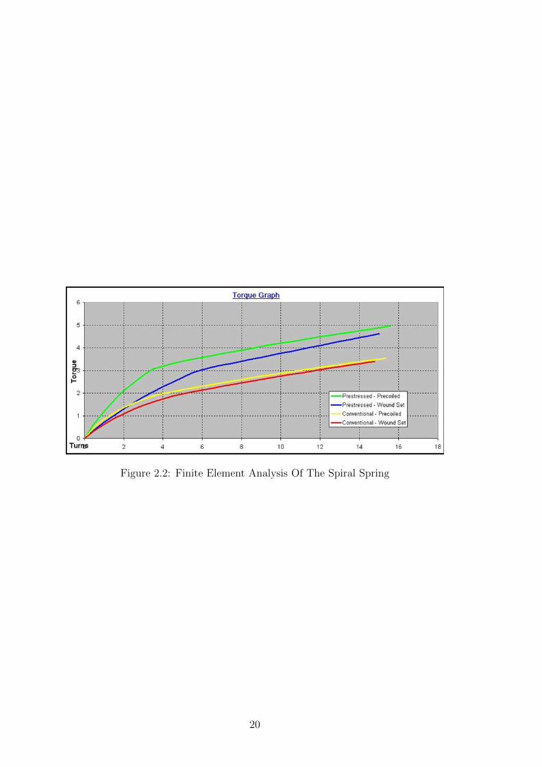
Figure 2.2: Finite Element Analysis Of The Spiral Spring
20
Chapter 3
Design of Prototype Model
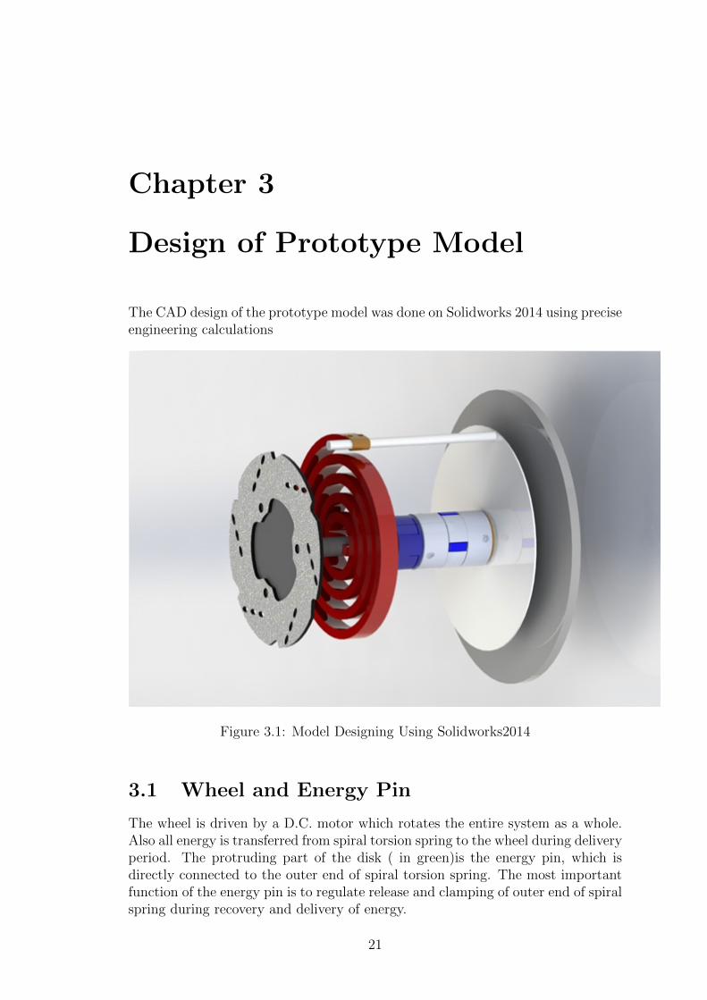
The CAD design of the prototype model was done on Solidworks 2014 using preciseengineering calculations
Figure 3.1: Model Designing Using Solidworks2014
3.1 Wheel and Energy Pin
The wheel is driven by a D.C. motor which rotates the entire system as a whole.Also all energy is transferred from spiral torsion spring to the wheel during deliveryperiod. The protruding part of the disk ( in green)is the energy pin, which isdirectly connected to the outer end of spiral torsion spring. The most importantfunction of the energy pin is to regulate release and clamping of outer end of spiralspring during recovery and delivery of energy.
21

Figure 3.2: Exploded View of the Model
Figure 3.3: 3D view of Wheel and Energy Pin
3.2 Shafts
The two shafts are concentric to each other and transmit rotating motion fromwheel to spiral spring and vice versa. Shaft 1 is connected to the wheel and shaft
22
2 is connected to the spiral spring and disk brake rotor.
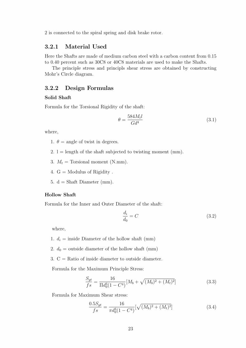
3.2.1 Material Used
Here the Shafts are made of medium carbon steel with a carbon content from 0.15to 0.40 percent such as 30C8 or 40C8 materials are used to make the Shafts.
The principle stress and principls shear stress are obtained by constructingMohr’s Circle diagram.
3.2.2 Design Formulas
Solid Shaft
Formula for the Torsional Rigidity of the shaft:
θ =584Mtl
Gd4(3.1)
where,
1. θ = angle of twist in degrees.
2. l = length of the shaft subjected to twisting moment (mm).
3. Mt = Torsional moment (N.mm).
4. G = Modulus of Rigidity .
5. d = Shaft Diameter (mm).
Hollow Shaft
Formula for the Inner and Outer Diameter of the shaft:
did0
= C (3.2)
where,
1. di = inside Diameter of the hollow shaft (mm)
2. d0 = outside diameter of the hollow shaft (mm)
3. C = Ratio of inside diameter to outside diameter.
Formula for the Maximum Principle Stress:
Sytfs
=16
Πd30(1 − C4)
[Mb +√
(Mb)2 + (Mt)2] (3.3)
Formula for Maximum Shear stress:
0.5Sytfs
=16
πd30(1 − C4)
[√
(Mb)2 + (Mt)2] (3.4)
23

Figure 3.4: 3D view of Shaft 1 and Shaft 2
3.2.3 Calculation Tables For Shaft
Table 3.1: Calculations for Hollow Shaft-1
Parameter Symbol
Torque, T 300
Rotation Speed,w 300
Shaft Outer Radius,c2 20
Shaft Inner Radius,c1 18
Shaft Length,L 100
Modulus of Rigidity,G 78
3.3 OneWay Clutch
This assembly is designed to allow rotation in only one direction. The hub isattached to a shaft, which in turn is attached to a driving mechanism. When thehub rotates counter-clockwise relative to the ring, the roller slips on the inside ofthe ring. If the hub rotates clockwise, then the spring allows the roller to wedgebetween the hub and the ring, causing the two to lock and rotate together. Forproper operation the contact angle between the roller and the ring must be be-tween 8 and 6 degrees.
24

Table 3.2: Calculations for Hollow Shaft-2
Parameter Symbol
Maximum Shear Stress 300
Angle of twist 300
Power Requirement 20
Polar Moment of Inertia 18
Figure 3.5: 2D view of oneway clutch
Figure 3.6: 3D view of oneway clutch
3.4 Dog Clutch
The dog clutch governs the relative motion between the two shafts.In engineering, a ”dog” is a tool or device used to lock two components in
25

relation to each otherA dog clutch is a type of clutch that couples two rotating shafts or other
rotating components not by friction but by interference. The two parts of theclutch are designed such that one will push the other, causing both to rotate atthe same speed and will never slip.
Figure 3.7: 3D view of Dog Clutch
26

3.5 Bearings
The main function of the bearings is to provide relative motion between shaft 1and shaft 2.
3.5.1 Bearing Materials
The bearing material which will be using here to manufacture our bearings isbronze cause of its quality and characteristics such as strength and it can alsowithstand high pressures.
3.5.2 Bearing Dimensions
Dimensions of Bearing 1 :- Outer diameter - 52mm Inner diameter 40mm Dimen-sions of Bearing 2 :- Outer diameter 32mm Inner diameter 20mm The dimensionsof the bearings were selected from SKF standard bearing table as per design re-quirements.
Figure 3.8: 3D view of Bearing 1 and Bearing 2
3.6 Jaw Coupling
A jaw coupling is a type of general purpose power transmission coupling that alsocan be used in motion control (servo) applications. It is designed to transmittorque (by connecting two shafts) while damping system vibrations and accom-modating misalignment, which protects other components from damage.
Jaw coupling was selected for this design because of its following advantages:
1. The Zero-backlash backlash feature of this coupling are best suited for ap-plications that rely on a stop-and-go type of movement.
27

2. The coupling has high accuracy in order to perform any number of precisiontasks which is a major design requirement.
Figure 3.9: 3D view of Jaw Coupling
28

Chapter 4
Modelling In MATLAB UsingSimulink
One of the main aims of this project was to develop plant model of the systemand simulate it using MATLAB and Simulink.
Iteration models were developed and simulated.
ITERATION 1
Figure 4.1: Iteration 1
A stepped signal was built using signal builder and sent to a torque source todrive the entire system. A wheel having interia 0.1 kgm2 , shaft of given dimensionsand a nonlinear rotation spring was added to the model.As flat spiral springs have non linear torque output at greater angular rotationthus a nonlinear spring was chosen for the model.
29

4.1 Generation of Archimedean spiral
The Archimedean spiral is a spiral named after the 3rd century BC Greek math-ematician Archimedes. It is a locus of points corresponding to the locations overtime of a point moving away from a fixed point with a constant speed along a linewhich rotates with constant angular velocity.
As Archimedean spiral is a mathematical representation of a spiral torsion spring, acode was written for matlab function block in Simulink to generate an Archimedeanspiral.
Figure 4.2: Matlab code for Archimedian spiral
Here,
n is number of points in path.
INITANGLE is radians until path begin
ENDANGLE is radians until path ends
(a,b): spiral parameters (in locator units!)
30

Figure 4.3: Matlab code for Archimedian spiral
4.2 Mathematical model of spiral torsion spring
With the equations of spiral torsion spring as explained in earlier chapters a Mat-lab function Simulink block was created. Following was the code written for thefuction block.
function a = fcn(m)
1. E = 30000000;
2. L = 157.48;
3. b = 0.59;
4. t = 0.19;
5. y = (6 ∗ L ∗ (m ∗ 8.85))/(3.14 ∗ E ∗ b ∗ t3);
6. a = y*360;
31

end
After an initial coding the block was tested in a new model
Figure 4.4: Veryfing the code in a new model
Here the value in constant block is 16.9 which is the Moment by which outerend of the spring is rotated keeping the centre fixed. The angular deflection isdigitally displayed in the display block.
Similarly a MATLAB function block relating the equations of stress and mo-ment is also created. The code is shown below
. function stress = fcn(m)
b = 15;t = 5;
stress = (6 ∗ (m ∗ 8.85))/(b ∗ t2 ∗ 145.03);
endSimulink model of Iteration 2 is also created and the two matlab function
blocks representing spiral torsion spring is added to it. Thus now we can contin-uously monitor the stresses and deflections in the spring.
After running the Simulation following results were obtained.The torque output of the shaft, deflection and stresses in the spring can be
seen through scope.
32

Figure 4.5: iteration 2
Figure 4.6: Input Signal is built using signal builder
Figure 4.7: The deflection in the spring vs time graph
33

Figure 4.8: Stresses generated in the spring with respect to time
34
Chapter 5
Conclusion and Future scope ofthe project
Our project team successfully completed design of prototype model using CADmodelling software Solidworks 2014. An intensive research was done on spiral tor-sion springs to understand the working principle develop its mathematical model.Precise calculations was done in excel and then simulated in Matlab.
The team believes with more time, that the system could be completed to allof its original requirements.
5.1 Future scope
More iteration models can be developed in matlab and simulated for optimiza-tion. The main aim should be to reduce overall inertia of the system and limitthe mechanical losses in the system to attain optimum performance.Control system for the prototype can also be designed on MATLAB where diskbrakes, rotary actuators will have to be controlled by analysing appropriate read-ings for sensors. Using control design we can achieve higher eciency with timelycontrol of mechanical components, we can get more accurate readings with itsimplementation.The final aim of this project will be to develop a prototype model through propermanufacturing practises and testing it in comparison with the data attained throughsoftware simulations.
35
Chapter 6
Future Work to be done in NextSemester
6.1 A Test Bench Setup
A test bench setup has to be manufactured which shall be done by the nextsemester, which shall practically and visually explain the working and principlesof the model.
6.2 Model Optimization
The system model which we will be creating here ,have to be optimized so thatoverall inertia of the system is less. At this optimization of the system ,we willmainly try to limit the losses that we incur while we work on a practical test benchmodel.
36

Bibliography
[1] V.B.Bhandari Concepts of Spiral Torsional Spring and Shafts : Mc Graw HillEducation.
[2] S.S. Rattan Concepts of Bearing : Mc Graw Hill Education.
[3] Wikipedia Concepts of Wheel and Energy Pin, Dog Clutch and Jaw Coupligs: Google.
[4] Google Sources Other Concepts : Google.
[5] John Evan’s Son Inc. (2005) (Spring Calculations :) Keereweer, J. (2010).
[6] Springs and Things 2011 (Spiral Spring Designing :) Springs and Things In-corporated.
37