projection and viewing · perspective projection transformation •mapping of z is nonlinear...
TRANSCRIPT
Projection and viewing
Computer Graphics
CSE 167
Lecture 4
CSE 167: Computer Graphics
• Review: transformation from the object (or model) coordinate frame to the camera (or eye) coordinate frame
• Projection– Perspective projection
• Projective homogeneous coordinates
• Projective transformation
– Orthographic projection
• Viewing
CSE 167, Winter 2020 2
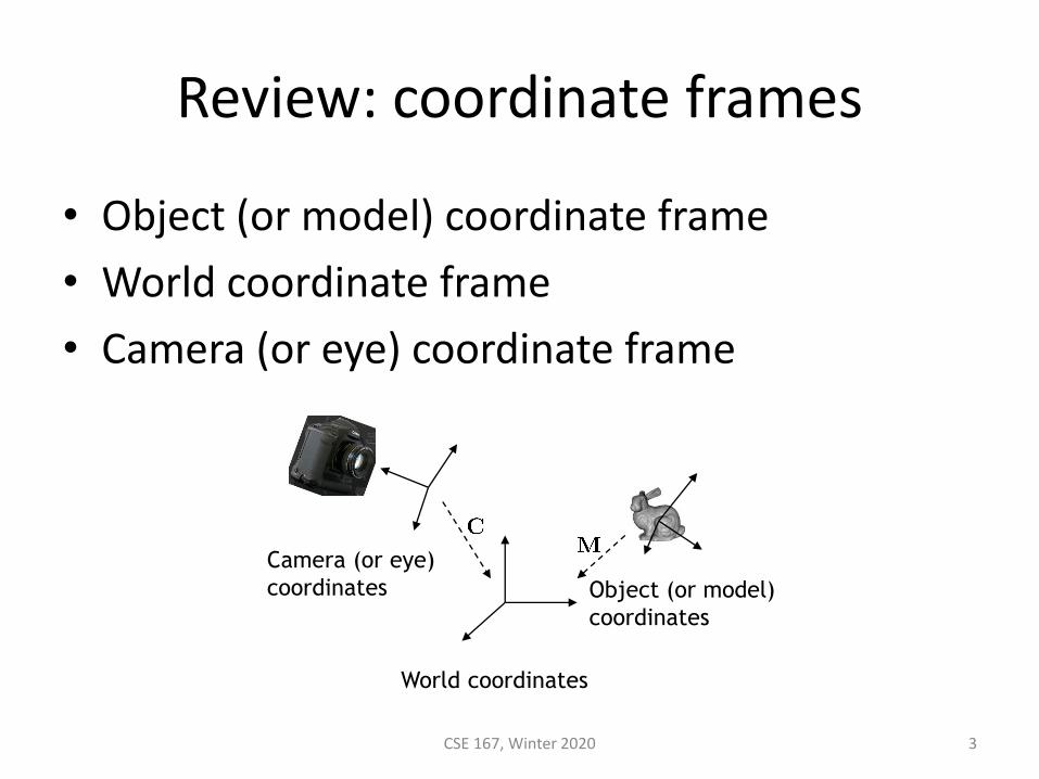
Review: coordinate frames
• Object (or model) coordinate frame
• World coordinate frame
• Camera (or eye) coordinate frame
CSE 167, Winter 2020 3
World coordinates
Object (or model)
coordinates
Camera (or eye)
coordinates
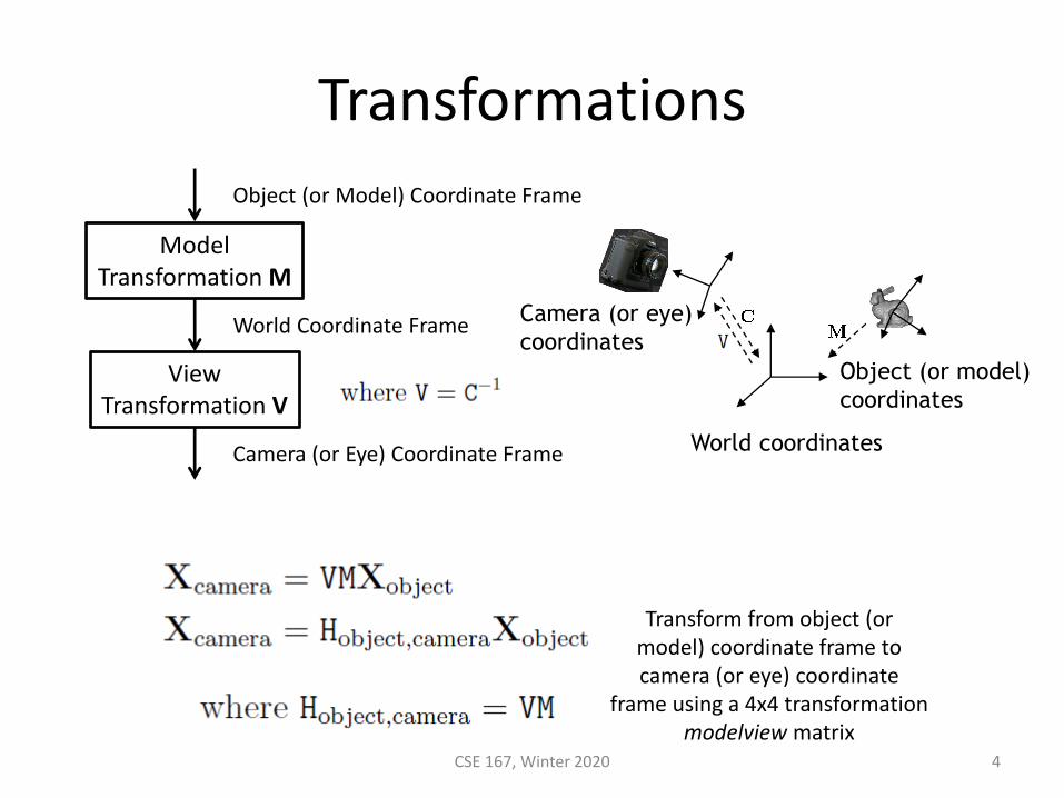
Transformations
CSE 167, Winter 2020 4
ModelTransformation M
ViewTransformation V
Object (or Model) Coordinate Frame
World Coordinate Frame
Camera (or Eye) Coordinate Frame
Transform from object (or model) coordinate frame to camera (or eye) coordinate
frame using a 4x4 transformation modelview matrix
World coordinates
Object (or model)
coordinates
Camera (or eye)
coordinates
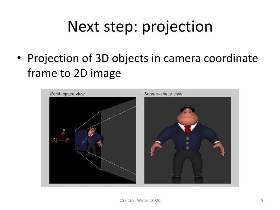
Next step: projection
• Projection of 3D objects in camera coordinate frame to 2D image
CSE 167, Winter 2020 5
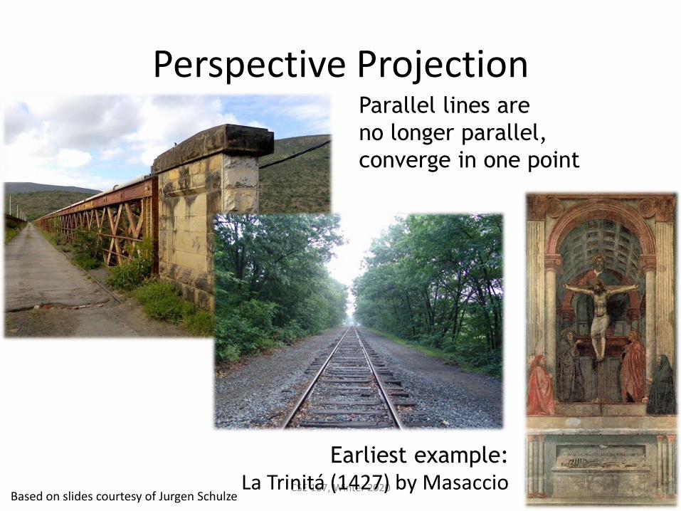
Perspective Projection
CSE 167, Winter 2020 6
Parallel lines are
no longer parallel,
converge in one point
Earliest example:La Trinitá (1427) by Masaccio
Based on slides courtesy of Jurgen Schulze
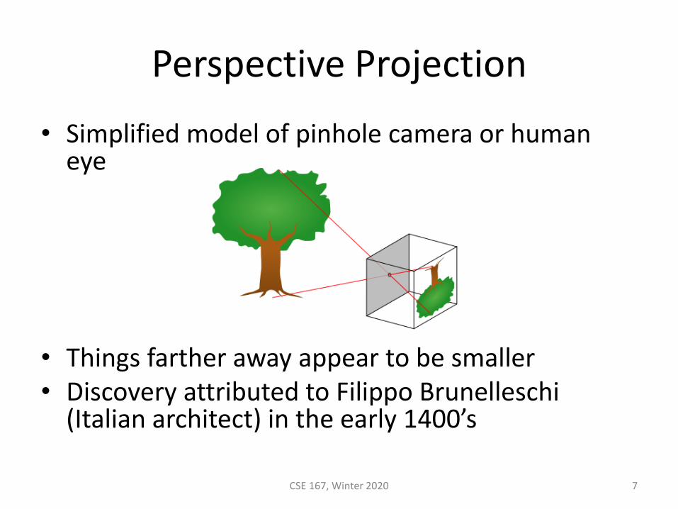
Perspective Projection
• Simplified model of pinhole camera or human eye
• Things farther away appear to be smaller• Discovery attributed to Filippo Brunelleschi
(Italian architect) in the early 1400’s
CSE 167, Winter 2020 7
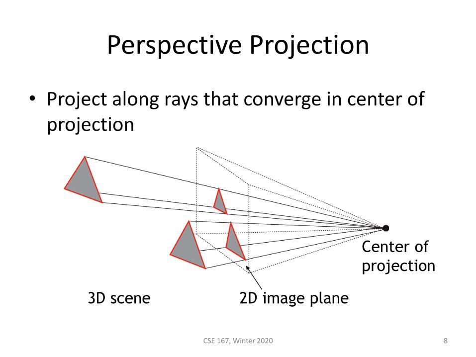
Perspective Projection
• Project along rays that converge in center of projection
CSE 167, Winter 2020 8
2D image plane
Center of
projection
3D scene
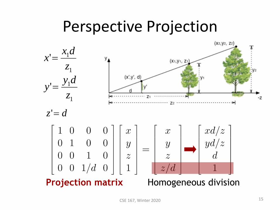
Perspective Projection
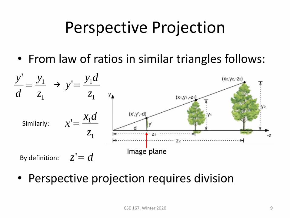
• From law of ratios in similar triangles follows:
• Perspective projection requires division
CSE 167, Winter 2020 9
Image plane
1
1'
z
y
d
y=
1
1'z
dyy =
dz ='
1
1'z
dxx =
→
Similarly:
By definition:
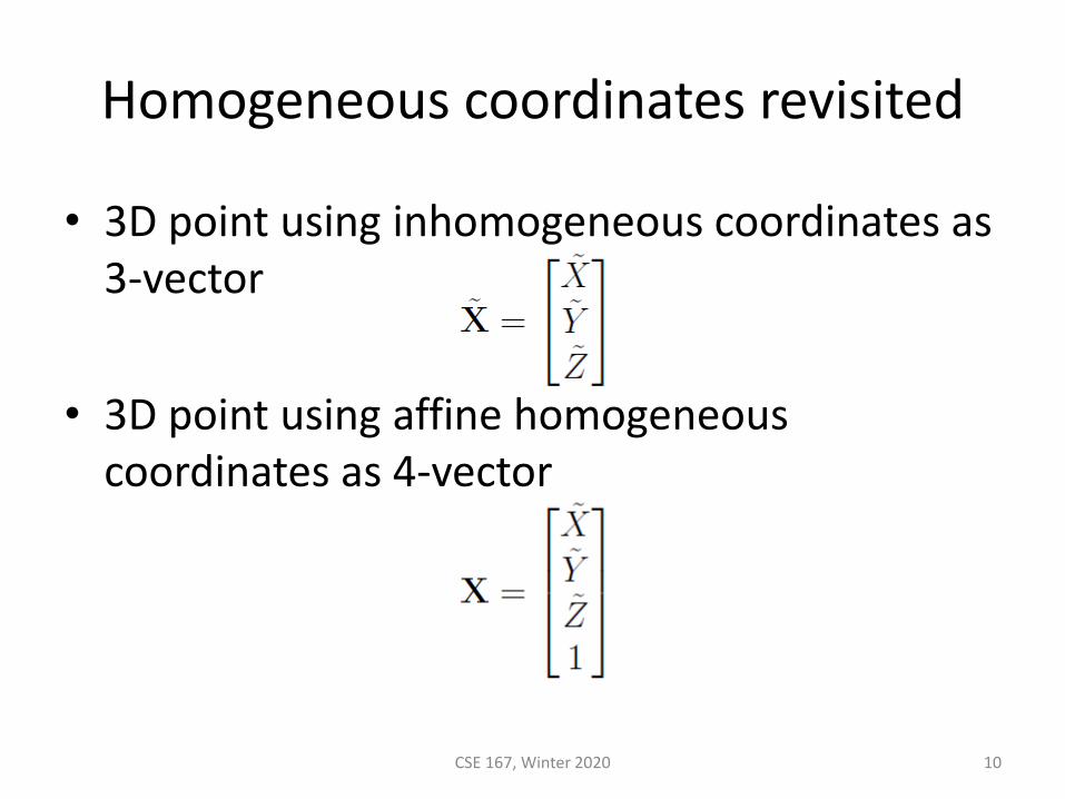
Homogeneous coordinates revisited
• 3D point using inhomogeneous coordinates as 3-vector
• 3D point using affine homogeneous coordinates as 4-vector
CSE 167, Winter 2020 10
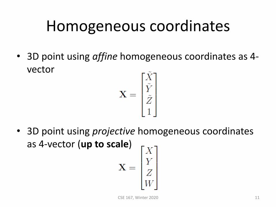
Homogeneous coordinates
• 3D point using affine homogeneous coordinates as 4-vector
• 3D point using projective homogeneous coordinates as 4-vector (up to scale)
CSE 167, Winter 2020 11
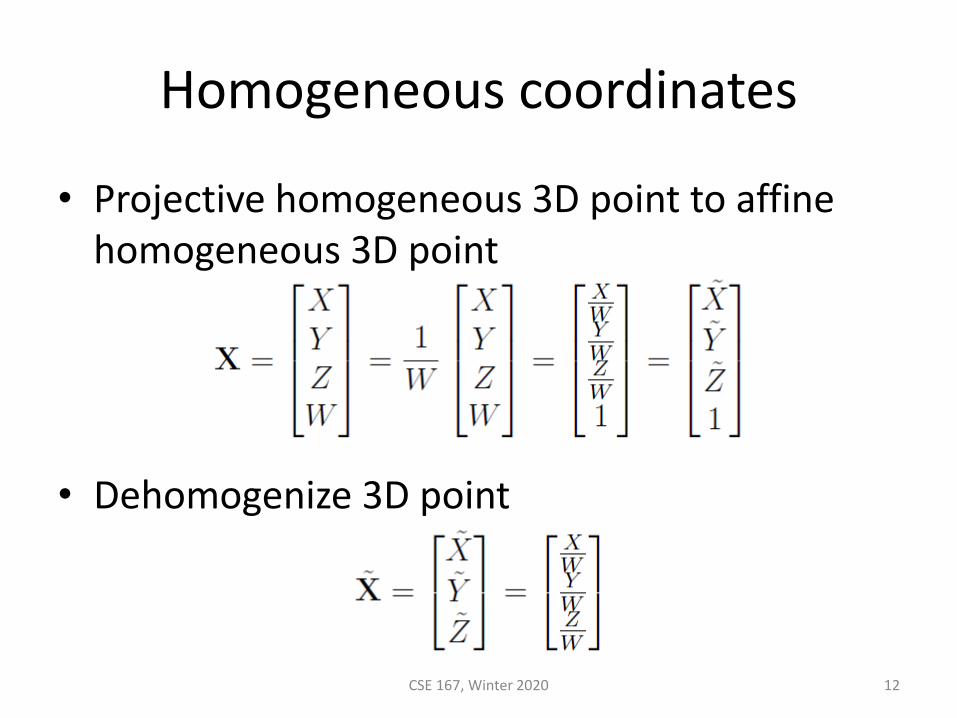
Homogeneous coordinates
• Projective homogeneous 3D point to affine homogeneous 3D point
• Dehomogenize 3D point
CSE 167, Winter 2020 12
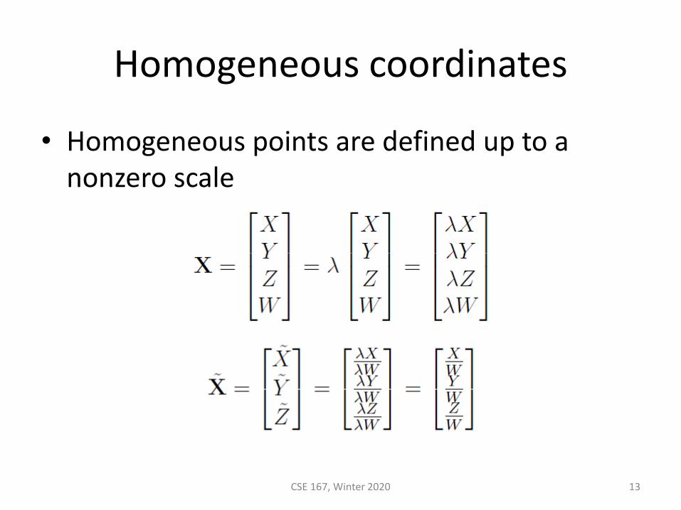
Homogeneous coordinates
• Homogeneous points are defined up to a nonzero scale
CSE 167, Winter 2020 13

Homogeneous coordinates
• When W = 0, then it is a point at infinity
• Affine homogeneous coordinates are projective homogeneous coordinates where W = 1
• When not differentiating between affine homogeneous coordinates and projective homogeneous coordinates, simply call them homogeneous coordinates
CSE 167, Winter 2020 14
Perspective Projection
Homogeneous divisionProjection matrix
1
1'z
dyy =
dz ='
1
1'z
dxx =
15CSE 167, Winter 2020
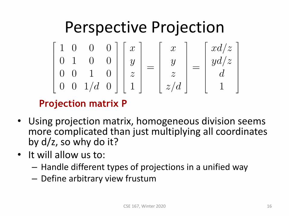
Perspective Projection
• Using projection matrix, homogeneous division seems more complicated than just multiplying all coordinates by d/z, so why do it?
• It will allow us to:– Handle different types of projections in a unified way– Define arbitrary view frustum
CSE 167, Winter 2020 16
Projection matrix P
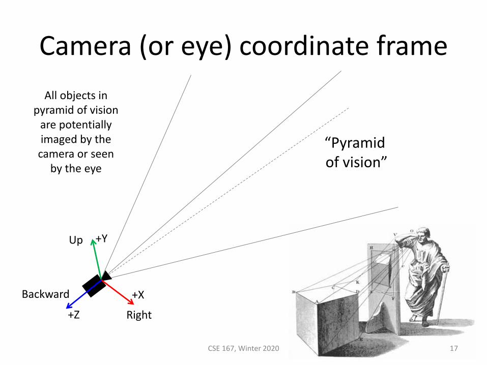
Camera (or eye) coordinate frame
CSE 167, Winter 2020 17
+X
+Y
+Z Right
Backward
Up
“Pyramid of vision”
All objects in pyramid of vision
are potentially imaged by the
camera or seen by the eye
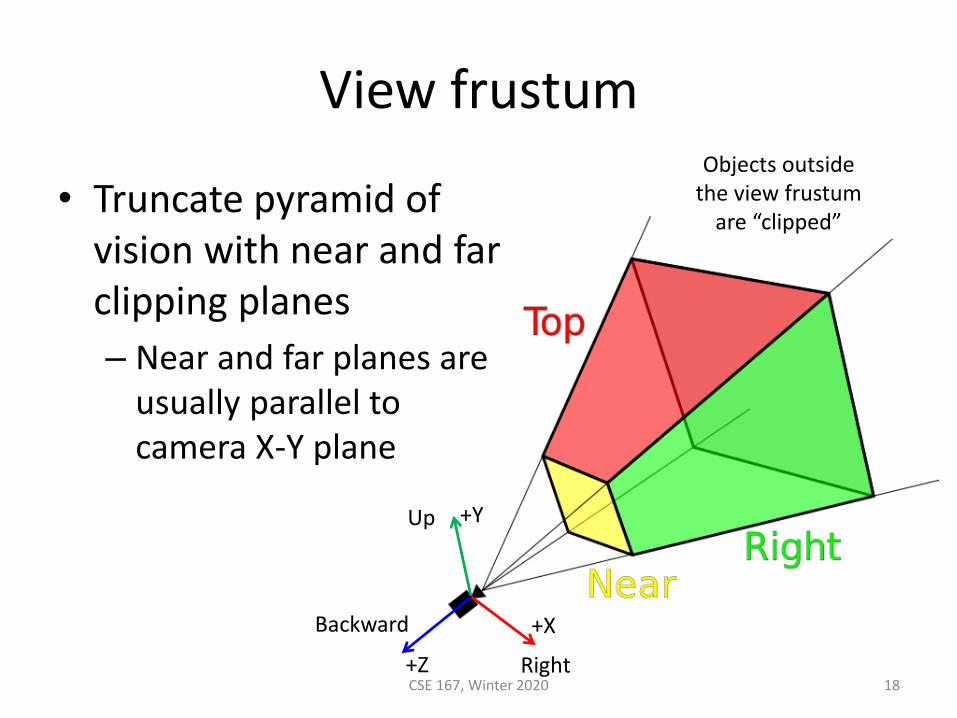
View frustum
• Truncate pyramid of vision with near and far clipping planes
– Near and far planes are usually parallel to camera X-Y plane
CSE 167, Winter 2020 18
+X
+Y
+Z Right
Backward
Up
Objects outside the view frustum
are “clipped”
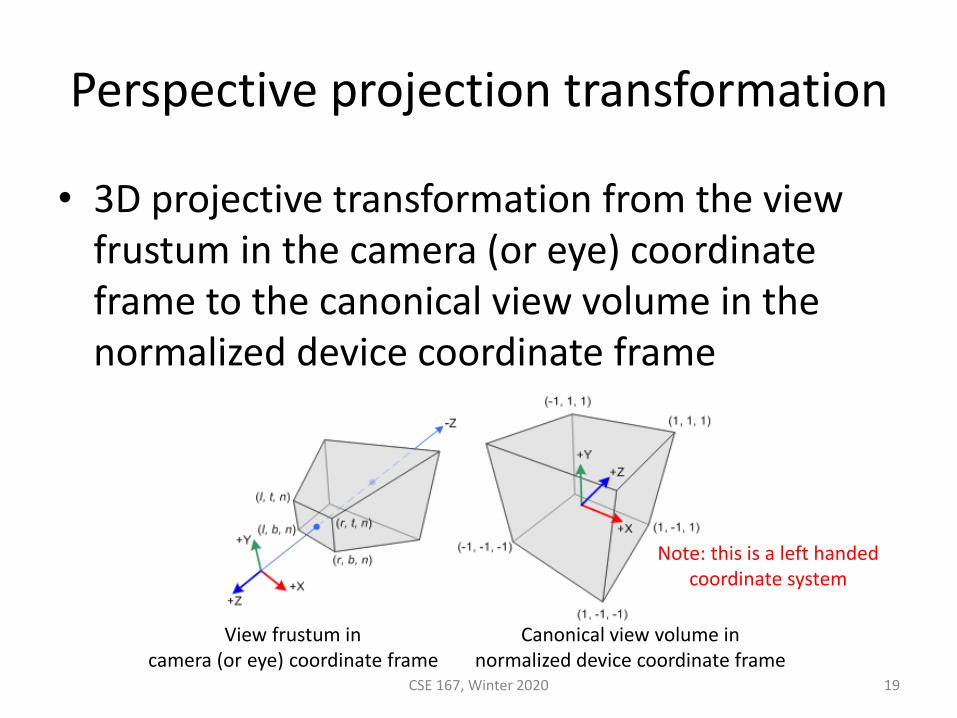
• 3D projective transformation from the view frustum in the camera (or eye) coordinate frame to the canonical view volume in the normalized device coordinate frame
Perspective projection transformation
CSE 167, Winter 2020 19
View frustum in camera (or eye) coordinate frame
Canonical view volume in normalized device coordinate frame
Note: this is a left handedcoordinate system
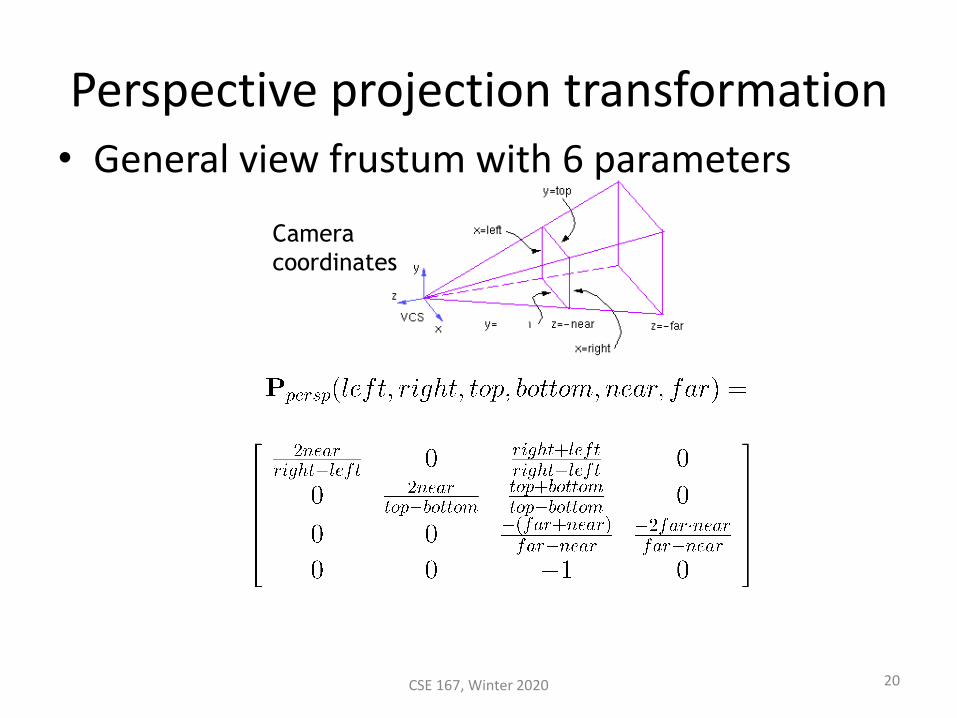
Perspective projection transformation• General view frustum with 6 parameters
Camera
coordinates
20CSE 167, Winter 2020
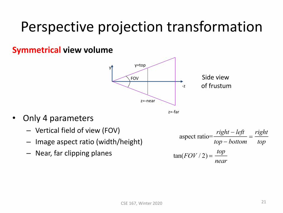
Perspective projection transformation
Symmetrical view volume
• Only 4 parameters– Vertical field of view (FOV)
– Image aspect ratio (width/height)
– Near, far clipping planes
-z
FOV
y
z=-near
z=-far
y=top
aspect ratio=right − left
top − bottom=right
top
tan(FOV / 2) =top
near
21CSE 167, Winter 2020
Side view of frustum
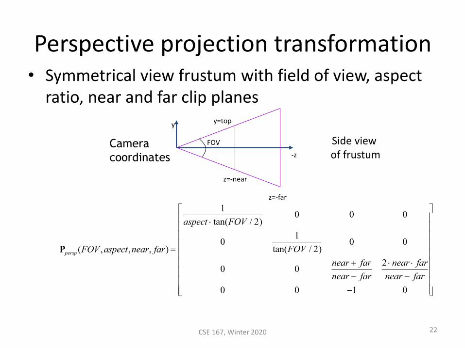
Perspective projection transformation• Symmetrical view frustum with field of view, aspect
ratio, near and far clip planes
Ppersp (FOV ,aspect,near, far) =
1
aspect tan(FOV / 2)0 0 0
01
tan(FOV / 2)0 0
0 0near + far
near − far
2 near far
near − far
0 0 −1 0
-z
FOV
y
z=-near
z=-far
y=top
Camera
coordinates
22CSE 167, Winter 2020
Side view of frustum
Perspective projection transformation
• Mapping of Z is nonlinear– Depth resolution in not uniform
• The previous projection transformations preserve depth on near and far planes– Very high precision at the near plane– Very low precision at the far plane
• The distance between near and far should be as small as possible to minimize precision issues– Do not set near = 0, far = infinity
• Setting near = 0 loses depth resolution
CSE 167, Winter 2020 23
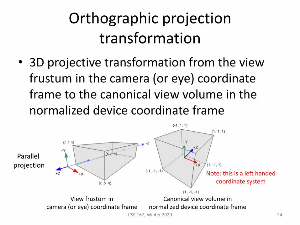
• 3D projective transformation from the view frustum in the camera (or eye) coordinate frame to the canonical view volume in the normalized device coordinate frame
Orthographic projection transformation
CSE 167, Winter 2020 24
View frustum in camera (or eye) coordinate frame
Canonical view volume in normalized device coordinate frame
Note: this is a left handedcoordinate system
Parallel projection
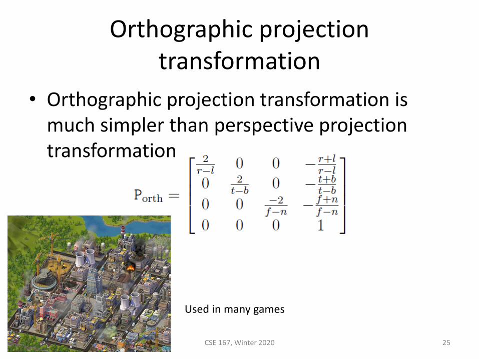
• Orthographic projection transformation is much simpler than perspective projection transformation
Orthographic projection transformation
CSE 167, Winter 2020 25
Used in many games
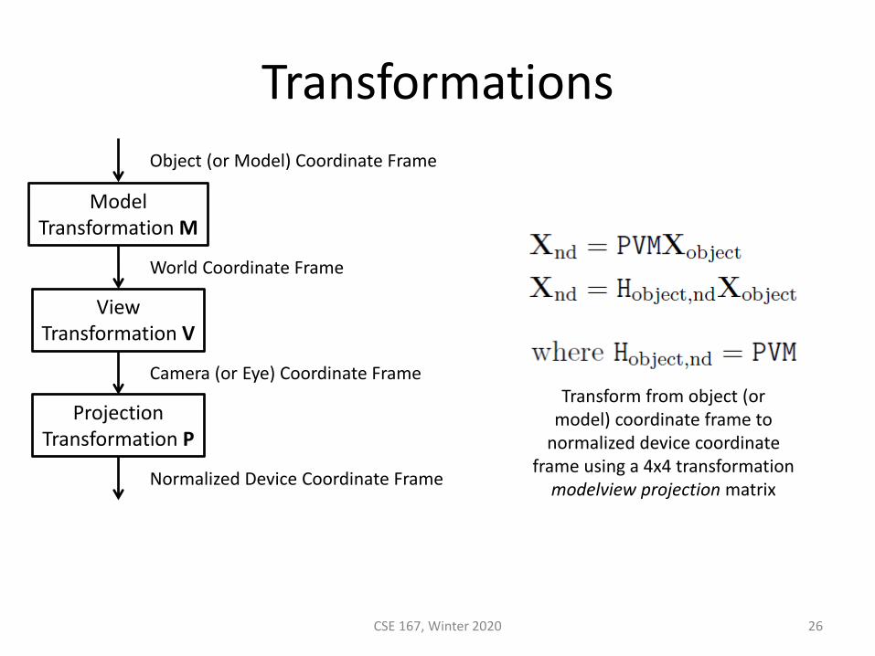
Transformations
CSE 167, Winter 2020 26
ModelTransformation M
ViewTransformation V
Object (or Model) Coordinate Frame
World Coordinate Frame
Camera (or Eye) Coordinate Frame
ProjectionTransformation P
Normalized Device Coordinate Frame
Transform from object (or model) coordinate frame to
normalized device coordinate frame using a 4x4 transformation modelview projection matrix
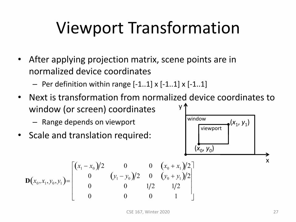
Viewport Transformation
• After applying projection matrix, scene points are in normalized device coordinates– Per definition within range [-1..1] x [-1..1] x [-1..1]
• Next is transformation from normalized device coordinates to window (or screen) coordinates– Range depends on viewport
• Scale and translation required:
CSE 167, Winter 2020 27
D x0 , x1, y0 , y1( )=
x1 − x0( ) 2 0 0 x0 + x1( ) 2
0 y1 − y0( ) 2 0 y0 + y1( ) 2
0 0 1 2 1 2
0 0 0 1
(x0, y0)
(x1, y1)
x
y
window
viewport
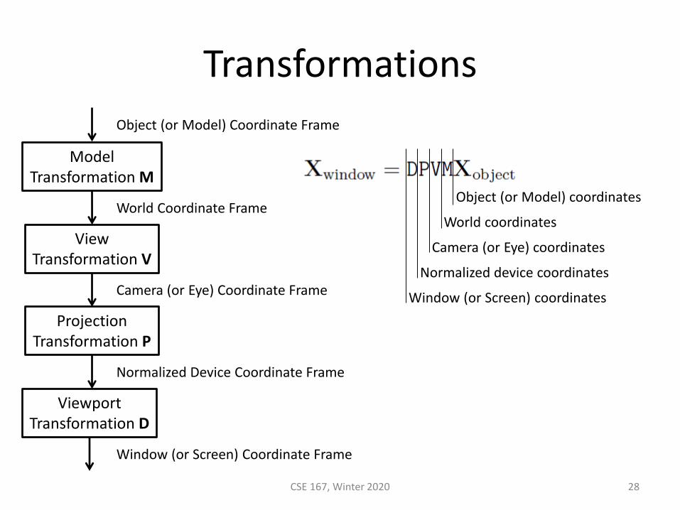
Transformations
CSE 167, Winter 2020 28
ModelTransformation M
ViewTransformation V
Object (or Model) Coordinate Frame
World Coordinate Frame
Camera (or Eye) Coordinate Frame
ProjectionTransformation P
Normalized Device Coordinate Frame
ViewportTransformation D
Window (or Screen) Coordinate Frame
Object (or Model) coordinates
World coordinates
Camera (or Eye) coordinates
Normalized device coordinates
Window (or Screen) coordinates
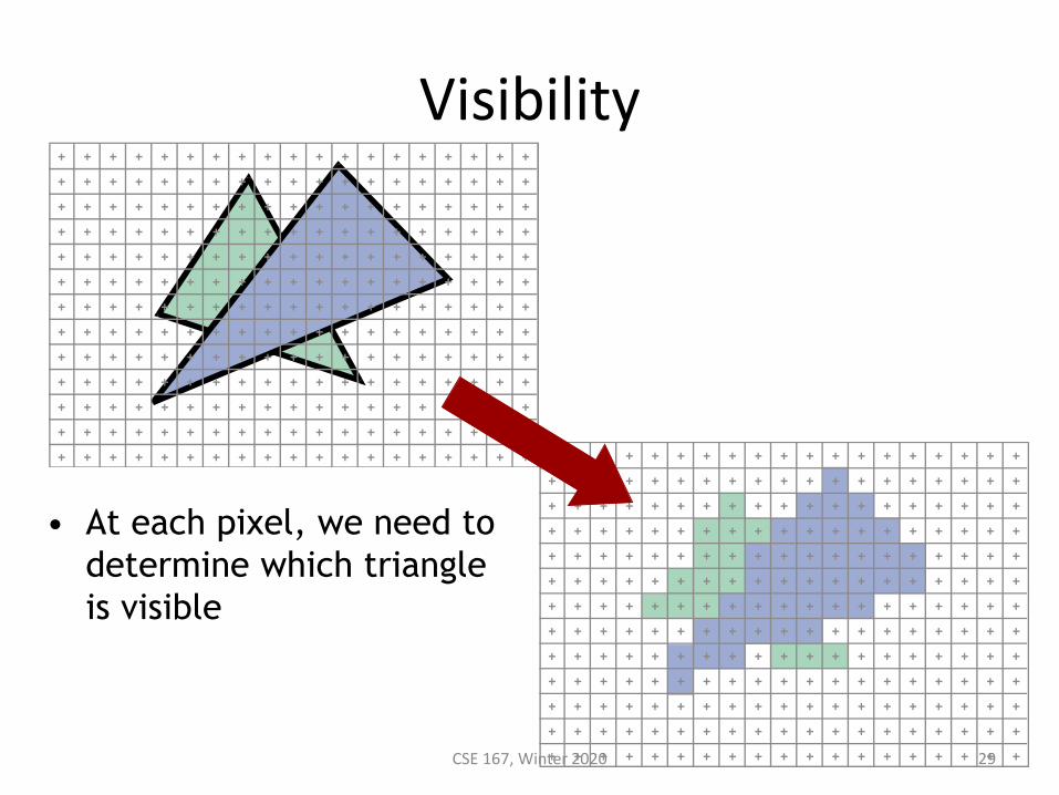
Visibility
CSE 167, Winter 2020 29
• At each pixel, we need to
determine which triangle
is visible
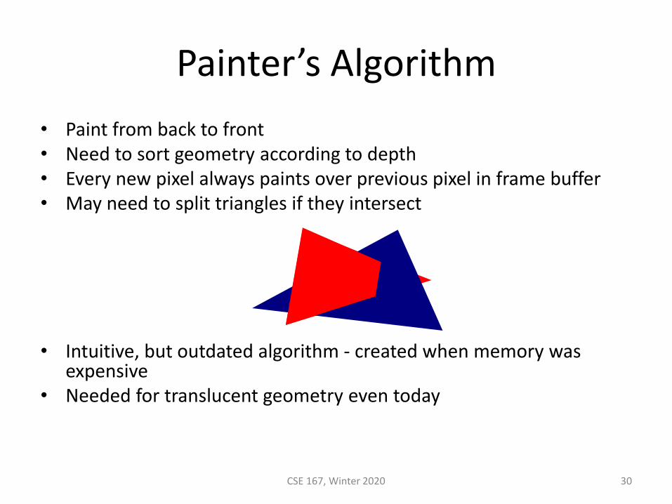
Painter’s Algorithm
• Paint from back to front• Need to sort geometry according to depth• Every new pixel always paints over previous pixel in frame buffer• May need to split triangles if they intersect
• Intuitive, but outdated algorithm - created when memory was expensive
• Needed for translucent geometry even today
CSE 167, Winter 2020 30
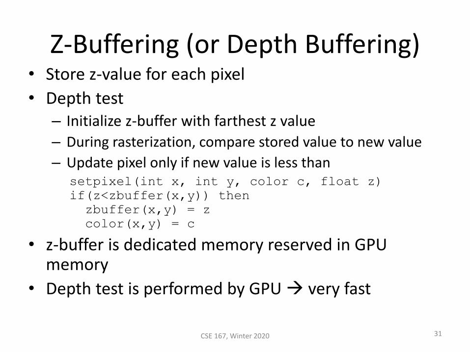
Z-Buffering (or Depth Buffering)• Store z-value for each pixel
• Depth test– Initialize z-buffer with farthest z value
– During rasterization, compare stored value to new value
– Update pixel only if new value is less thansetpixel(int x, int y, color c, float z)
if(z<zbuffer(x,y)) then
zbuffer(x,y) = z
color(x,y) = c
• z-buffer is dedicated memory reserved in GPU memory
• Depth test is performed by GPU → very fast
31CSE 167, Winter 2020
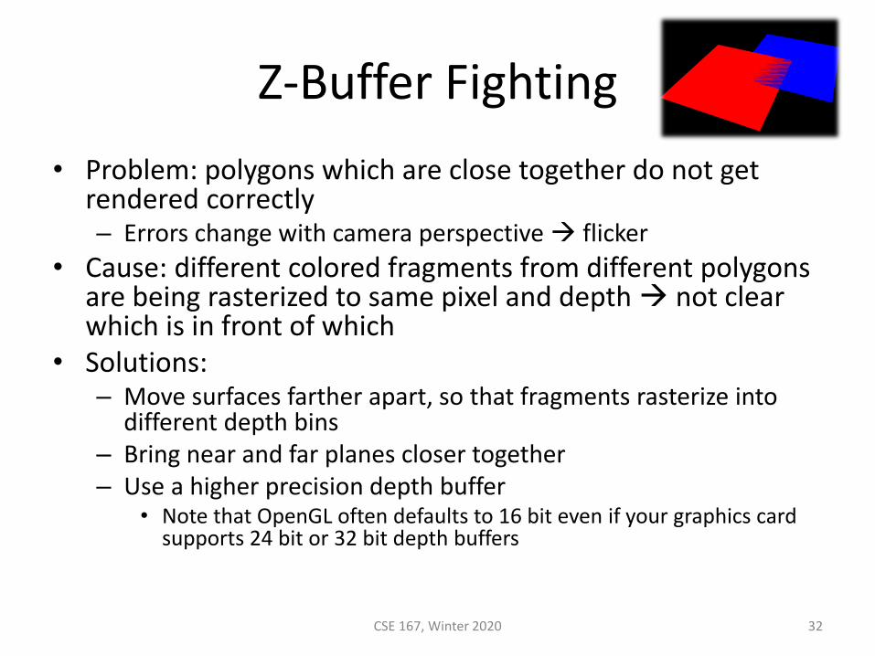
Z-Buffer Fighting
• Problem: polygons which are close together do not get rendered correctly– Errors change with camera perspective → flicker
• Cause: different colored fragments from different polygons are being rasterized to same pixel and depth → not clear which is in front of which
• Solutions:– Move surfaces farther apart, so that fragments rasterize into
different depth bins– Bring near and far planes closer together– Use a higher precision depth buffer
• Note that OpenGL often defaults to 16 bit even if your graphics card supports 24 bit or 32 bit depth buffers
CSE 167, Winter 2020 32
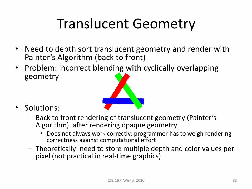
Translucent Geometry
• Need to depth sort translucent geometry and render with Painter’s Algorithm (back to front)
• Problem: incorrect blending with cyclically overlapping geometry
• Solutions:– Back to front rendering of translucent geometry (Painter’s
Algorithm), after rendering opaque geometry• Does not always work correctly: programmer has to weigh rendering
correctness against computational effort
– Theoretically: need to store multiple depth and color values per pixel (not practical in real-time graphics)
CSE 167, Winter 2020 33