project turtle - spacecraft.ssl.umd.edu · stuart douglas, andrew ellsberry, sara fields, david...
TRANSCRIPT

Project TURTLE Terrapin Undergraduate Rover for Terrestrial
Lunar Exploration
University of Maryland
May 2008
Faculty Advisors: Dr. David Akin and Dr. Mary Bowden
David Berg, James Briscoe, Kanwarpal Chandhok, Enrique Coello, Joshua Colver, Aaron Cox,
Stuart Douglas, Andrew Ellsberry, Sara Fields, David Gers, Zohaib Hasnain, Ali Husain,
Madeline Kirk, Jason Laing, May Lam, Jason Leggett, Michael Levashov, Ryan Levin, Joseph
Lisee, Omar Manning, Thomas Mariano, Jessica Mayerovitch, Brian McCall, David McLaren,
Adam Mirvis, Ryan Murphy, Aleksandar Nacev, Hasan Oberoi, Ugonma Onukwubiri, Stephanie
Petillo, Tiffany Russell, Matthew Schaffer, Ali-Reza Shishineh, Jacob Zwillinger

TURTLE 1
I. OVERVIEW
A. NASA Constellation Program
THE Constellation program is the current drivingforce behind NASA’s future manned space program.
In the quest to return to the moon, NASA is focusing itsattention to developing a permanent lunar outpost, andfocusing all of its infrastucture at that site. However,many of the scientifically interesting sites will not bewithin surface access distance from the outpost, and canbe reached only via a dedicated sortie-mode explorationmission, currently baselined as four crew for seven dayson the surface. The Altair lander used for these sortiemissions will be highly mass constrained, and will notallow the transport of a pressurized rover for extendedexploration at the sortie site.
The Terrapin Undergraduate Rover for TerrestrialLunar Exploration (TURTLE) concept is designed tocomplement and enhance the Constellation program, byexploring the minimum size and mass limits for a pres-surized rover while developing a concept of operationsthat allow the rover to be deployed to the sortie landingsite independent of the Altair lander. The TURTLEconcept will augment sortie missions on the moon byproviding increased exploration range for astronauts. Itallows a pair of astronauts to venture up to 25 kmaway from the lander during a three-day traverse, andsupports two such traverses during the sortie mission.This represents a twelve-fold increase in exploration areaand duration as compared to an Apollo-style unpressur-ized rover, without requiring additional Ares V launches;the resultant lunar exploration program is significantlyenhanced without impact to the development of thebaseline Constellation architecture.
A TURTLE-class small pressurized rover also pro-vides significant benefits during the development andoperation of a lunar outpost. During construction, TUR-TLE can be used as a support station, transportingastronauts around the construction area. Extensive lunarsurface extravehicular activities (EVAs) are facilitated bythe simple ingress/egress capabilities of the TURTLEsuitports, which allow the astronauts to take a quickbreak for relaxation or nourishment. After the outpostis constructed, TURTLE enhances the mobility of theastronauts. In its outpost configuration, TURTLE canperform an extended mission with twice the range ofthe sortie rover, and can support two astronauts for sixdays.
B. Rover Overview
Figure 1 shows the rover and its coordinate system.The cabin pressure shell has an outside diameter of 1.83m and is 2.43 m long. It consists of two layers of graphiteepoxy, wrapped around an aluminum-alloy frame. The
rover as a whole is 3.45 m long between the tip of eachwheel, 3.24 m wide, and 2.93 m high (to the top of theLIDAR antenna). The total initial mass of the rover, withall consumables but no personnel, is 1750 kg.
Figure 1. The TURTLE Exterior
Figure 2. TURTLE Components
Figure 2 shows the external layout of TURTLE, whichis designed to meet several constraints. All items are atleast 0.5 meters above the ground for the rover to beable to drive over a 0.5 meter obstacle as dictated byrequirements. Equipment on the outside cannot interferewith the movement of the wheels. Also all equipmentis located where it is secured directly to the chassisinstead of the pressure shell, where it cannot be damagedin a driving crash, and does not interfere with theline of sight of the antennas. The science package andequipment are easily accessable by astronauts on EVA.Finally, to maximize the rover’s stability while driving,
TURTLE 2
Table ISTABILITY MARGINS
Tilt Direction Left Right Forward BackwardCritical Angle 48◦ 50◦ 38◦ 37◦
the equipment is placed as low to the ground and assymmetric about the geometric center as possible. Fueltanks are placed evenly on both sides of the rover tominimize the shift in CG as these are drained.
Ingress and egress for the astronauts are provided bya pair of suitports on the back of the cabin which areaccessible via an adjustable external platform, whichalso provides a control station for driving the vehicleexternally during an EVA.
Table I shows the static stability limits for the worst-case situation in each direction. These take into accountthe change in mass from consumables and the varyingpositions of the astronauts. The rover is able to traversea 20 degree slope in any direction in all expected loadingconfigurations with significant margins.
C. Concept of Operations
TURTLE will launch on a Delta IV-H directly intoa trans-lunar injection orbit (TLI), with a maximumpayload capacity of 10200 kg.[3] By launching directlyinto TLI, staging in low earth orbit is avoided, whichincreases the maximum landable mass on the lunarsurface. The total time spent in TLI varies from 4-6days, depending on the mission profile. After completingthe lunar transfer stage, the rover will park in a lowlunar orbit and initiate descent along a Hohmann transferellipse to the surface. At a height of 2000 m, the firststage, a retro engine, will separate from the rover andlanding system so that the landing system can landunencumbered on the surface.
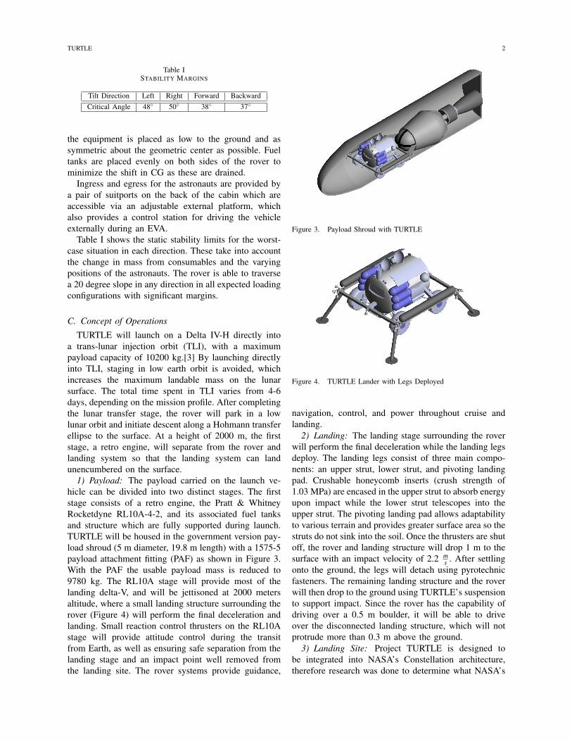
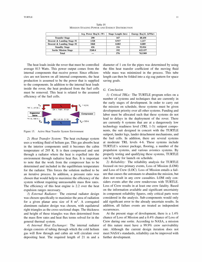
1) Payload: The payload carried on the launch ve-hicle can be divided into two distinct stages. The firststage consists of a retro engine, the Pratt & WhitneyRocketdyne RL10A-4-2, and its associated fuel tanksand structure which are fully supported during launch.TURTLE will be housed in the government version pay-load shroud (5 m diameter, 19.8 m length) with a 1575-5payload attachment fitting (PAF) as shown in Figure 3.With the PAF the usable payload mass is reduced to9780 kg. The RL10A stage will provide most of thelanding delta-V, and will be jettisoned at 2000 metersaltitude, where a small landing structure surrounding therover (Figure 4) will perform the final deceleration andlanding. Small reaction control thrusters on the RL10Astage will provide attitude control during the transitfrom Earth, as well as ensuring safe separation from thelanding stage and an impact point well removed fromthe landing site. The rover systems provide guidance,
Figure 3. Payload Shroud with TURTLE
Figure 4. TURTLE Lander with Legs Deployed
navigation, control, and power throughout cruise andlanding.
2) Landing: The landing stage surrounding the roverwill perform the final deceleration while the landing legsdeploy. The landing legs consist of three main compo-nents: an upper strut, lower strut, and pivoting landingpad. Crushable honeycomb inserts (crush strength of1.03 MPa) are encased in the upper strut to absorb energyupon impact while the lower strut telescopes into theupper strut. The pivoting landing pad allows adaptabilityto various terrain and provides greater surface area so thestruts do not sink into the soil. Once the thrusters are shutoff, the rover and landing structure will drop 1 m to thesurface with an impact velocity of 2.2 m
s . After settlingonto the ground, the legs will detach using pyrotechnicfasteners. The remaining landing structure and the roverwill then drop to the ground using TURTLE’s suspensionto support impact. Since the rover has the capability ofdriving over a 0.5 m boulder, it will be able to driveover the disconnected landing structure, which will notprotrude more than 0.3 m above the ground.
3) Landing Site: Project TURTLE is designed tobe integrated into NASA’s Constellation architecture,therefore research was done to determine what NASA’s

TURTLE 3
Table IISCIENCE GOALS FOR CONSIDERED LANDING SITES
Site Name Science Goals
Gassendi Crater • Determine relation between auxiliary crater andits parent
• Explore ancient lava rilles• Survey crater wall
Tycho Crater • Determine age of impact crater• Establish accurate lunar chronology
Mare Nectaris • Test validity of cataclysm hypothesis• Study remnants of Tycho ejecta
Copernicus Crater • Examine nebulous ejecta ray system• Establish accurate lunar chronology
South Pole-AitkenBasin
• Determine age of impact basin• Find samples of lower crust and lunar mantle
• Test validity of cataclysm hypothesisSchrödinger Crater • Possible site for lunar outpost
• SPA science goals may be accomplished here
science goals are for returning to the Moon. The landingsite selection process for TURTLE incorporated many ofthe suggestions from the National Research Council’s2007 report for NASA’s Vision for Space Exploration[14] to make synthesis of the two programs easier. TableII shows a list of higher-priority landing sites that wereconsidered for project TURTLE.
A sample mission outline was also created forGassendi crater (see Figure 5), to show a concept ofa TURTLE mission. Once TURTLE has safely landedon the surface, it will self-checkout and autonomouslyrendezvous with the astronaut crew, who will land lessthan 10 km away. Two astronauts will enter TURTLEand use the rover for a three day mission, traveling 25km away from the crew lander. During the mission,astronauts will perform three EVAs where they willdeploy science packages and collect samples. Astronautswill also be able to drive the rover externally during EVAto expand scientific opportunity.
Figure 5. Depiction of a sortie-mode mission using TURTLE
4) Science Objectives: The science objectives of ourmission are to:• Deploy equipment for long-term data collection• Collect data for the lunar base design• Increase knowledge of the moon’s structure and
environment• Obtain samples for study on Earth
• Perform basic sample analysis on the moon• Increase understanding of lunar habitability
The science package consists of the Radioisotope Ther-moelectric Generator (RTG), Lunar Seismic Monitoring,Lunar Surface Gravimeter, Lunar Atmospheric Composi-tion Experiment, and Lunar Meteorites Experiment. Withthe RTG to serve as a power source, it will providepower for several years following deployment of theexperiments.
D. Requirements
Project TURTLE began with a provided list of 25Level One requirements. The following list includes therequirements that were highly influential in the designprocess.
1) The rover shall be capable of launching on anexisting lower-cost launch vehicle, and be a standalone addition to a Constellation sortie mission.
2) The rover shall be capable of autonomously off-loading from the lander.
3) The rover shall be capable of autonomously driv-ing up to 10 km to rendezvous with the crew.
4) The rover shall be capable of supporting a threeday mission with two crew members.
5) The rover shall be capable of traveling a 25 kmradius from the lander with a total travel distanceof 100 km between two sortie missions.
6) The rover shall accommodate crew sized rangingfrom 95th percentile American male to 5th per-centile American female.
7) Rover shall provide life support for nominal mis-sion plus 48 hours contingency.
8) Rover shall support nominal two-person EVAswithout cabin depressurization.
9) Access to and from the surface shall be compatiblewith safe traverses by pressurized subjects in Earthgravity.
10) Rover shall have a maximum operating speed ofat least 15 km
hr on level, flat terrain.11) Rover shall be designed to accommodate a 0.5 m
obstacle at minimal velocity and a 0.1 m obstacleat a velocity of 7.5 km
hr .12) Rover shall be designed to accommodate a 20
degree slope in any direction at a speed of at least5 km
hr with positive static and dynamic margins.
E. Rover Variations
The TURTLE design is based off of the requirementslisted above. However, modifications were made to thelunar design to account for other programs or functions.The four rover designs developed are the lunar rover,mock-up rover, outpost rover, and field rover. Whilethe lunar rover and mock-up are parallel designs that

TURTLE 4
support one another, the outpost and field rovers aresupplemental designs based off the lunar design.
a) Lunar Rover: The lunar rover, or flight rover,shown in Figure 1 is the baseline design for the differ-ent rover variations and is derived from the level onerequirements distributed at the beginning of the project.The lunar rover will be launched to and land on themoon to perform two sortie missions. The lunar roveris designed to survive in the space environment and isentirely self-contained in terms of consumables (i.e. fuel,food, water, air). One of the major defining points isthat the lunar rover is a “disposable” rover that is onlymeant to survive for two three-day sortie missions witha two-day contingency. As such, it is not designed to berefueled or replenished for additional missions.
b) Rover Mock-up: The rover mock-up is a lowfidelity mock-up of the lunar rover cabin that was usedfor design and testing of the interior layout. It wasinitially derived from the lunar rover designs, but throughtesting influenced TURTLE’s final design. The goal ofconstructing the mock-up was to allow test subjectsto see and feel how the dimensions and placement ofinterior items influence comfort and ease of use in thecabin. Testing was isolated to console design, interiorlayout, window size and placement, sleeping options,and suitport operations and functionality. The funds tosupport the construction of the TURTLE mock-up camefrom Maryland Space Grant Consortium. As shown inFigure 6, the mock-up has a simple exterior and func-tional interior for human factors testing and habitabilityassessments. All testing protocols were approved throughthe University of Maryland Institutional Review Boardfor the use of humans as experimental subjects
c) Outpost Rover: Part of the Constellation Pro-gram is to develop a lunar outpost to support long-duration missions on the moon. With some modifica-tions, TURTLE can also be used as a support and multi-use rover for the planned outpost. Similar to the originallunar rover, the outpost rover can, as a minimum, go onthree-day missions and support a crew of two people.However, upon return, consumables in TURTLE arereplenished and damaged parts are serviced. OutpostTURTLE will also have a shirt-sleeve entrance so therover can dock with the outpost and allow easy accessfor servicing and replenishing the interior of the vehicle.It is designed for multiple missions and an extended lifeon the lunar surface.
d) Field Rover: To test the overall concept of apressurized lunar rover for surface exploration, a highfidelity mock-up of TURTLE was designed to provide ameans for Earth testing in a simulated lunar environment.The field rover design is based off the lunar roverwith modifications to account for changes on Earthincluding increased gravity, external atmosphere, and a
Figure 6. Rover Mock-up
nearby support team. Unlike the cabin mock-up, the fieldTURTLE would be capable of supporting a three-day testmission in the desert with two crew members performingEVAs and living in the rover. The field TURTLE alsowould be capable of independent movement and powergeneration. Although the hardware would not be flightready, the field rover is a high fidelity mock-up used totest the overall concept and major systems of the rover.
II. DESIGN
A. Terramechanics
1) Wheels: A major component of TURTLE’s designwas to determine the ideal number of wheels. TURTLEachieved a positive drawbar pull climbing up a hill oran obstacle with 4 wheels and 8 grousers as shown inFigure 7. The number of wheels and grouser height wasanalyzed by using Bekker’s theory. The wheels are 1.0 min diameter, to accommodate the Level One requirementof clearing a 0.5 m obstacle. A wheel-width of 0.3 mminimizes the wheel sinkage and power use. The wheelsare made out of Aluminum 2024 and have a grouserheight of 0.015 m. The hub-rim design protects themotors from impact during driving. The tires are non-pneumatic, airless, and fused onto the wheel. This designimproves shock absorbance, lowers energy consumption,and reduces the rolling resistance.
2) Mobility: TURTLE can execute a turn with amaximum turning radius of 9.2 m at a speed of 15 km
hr .It will be steered by four linear actuators that will allowthe wheels to turn at an 18° steering angle to maintain

TURTLE 5
Figure 7. Drawbar Pull VS Slope: Justifaction for 4 wheels and 8grousers
stability at the maximum speed. The rover can come to afull stop at a maximum distance of 4.34 m in 2.1 s, froma speed of 15 km
hr . The stopping distance was determinedby the crew sight lines from the driving window. Toaccommodate the stopping distance, TURTLE uses atwo part braking system through a DC drive motor. Thisincludes magnetic and friction brakes, which are madeout of titanium carbide due to its high heat tolerance.
3) Motors: The drive system uses DC brushless mo-tors due to their simple nature. It can produce torques ofapproximately 24 N-m per motor and requires only 10 Aof current. The motor is fully encased in a thin (0.1mm)shell of 2024 Aluminum Alloy which will protect it fromdust particles kicked up by the wheel system.
The motor itself is mounted along the strut of thevehicular suspension. This section moves upward alongwith the wheels when obstacles are encountered. Thestruts bear the weight of the entire vehicular frame,which is an order of magnitude more massive than thepropulsion system. A series of miniature struts stabilizethe motor, connect to upper elements of the strutswithout impeding the suspension, and weigh 5 kg each,for a total support system mass of 26 kg.
The motors each extend a 2024 aluminum driveshaftinto 5:1 parallel reduction gear train, oriented directlyat the center of the wheel and connected to it at thewheel bearings. The length of the drive system allowsit to fit entirely within the confines of the wheels of thevehicle, without extending out at any point. The finalsystem design is outlined in TableIII. These motors area TRL 4 because they have not been space tested.
4) Steering: The rover suspension system allows forindividual control of each wheel to rotate a maximumangle of 60◦. To apply the torque to each wheel forcingturning, a linear actuator is attached to the wheel baseand the suspension system.
a) Calculation of Force Required: When calcu-lating the required force the linear actuator needs toapply to generate the torque on the wheel, a turningtime of 60◦ in 1 second was assumed. This time is theassumed response time of the wheel itself and does notinclude the response and speed of the linear actuator.The assumption is made that the linear actuator usedwill be able to respond at similar rates, if not faster.The relationship between the force required by the linearactuator when turning the wheel a certain angle wasdetermined. For a 60◦ turn, 450 N must be applied toeach wheel.
b) Calculation of Energy Needed: After determin-ing the required force the linear actuator needs to exertto turn the wheel, the energy required to supply to thelinear actuator was calculated. The energy required isrelated to the distance the actuator moves. This energycan then be converted into a power draw for each wheelactuator by averaging it over the time required to turncreating a relationship between the power draw and theturning angle. The highest power draw of 100 W perwheel was added into the power budget.
5) Suspension System: The rover has an independentsuspension because it has four independently steered andpowered wheels. Each wheel is connected to the restof the rover with a MacPherson strut. The suspensionsystem is designed to handle two loading cases: drivingover a 0.1 meter obstacle at a velocity of 7.5 km
hr duringdriving, and landing at up to 1 m
s . Based on analysis of alinear system of differential equations, a spring constantof 35 kN
m and damping constant 1 kN sm were chosen for
the suspension at each wheel.
B. Structures
Every structure in the rover is designed to have amargin of safety greater than zero against its most ex-treme loading case. For ease of fabrication and handling,metallic components are required to have a minimumthickness of 1 mm. Composites and sandwich structuresmust have a minimum thickness of 2 mm and 12 mm,respectively.
1) Chassis: The chassis frame is shown in Figure 8.All equipment mounted to the exterior of the rover isattached directly to the chassis frame. Four circular ringswrap around the rover’s inner pressure shell which areconnected by seven struts running the length of the rover,to absorb axial forces during launch. Additional struts areadded in the rear of the structure to support the suitports.Shock towers are located at the front and back end ofthe chassis to absorb impact loads from the wheels.
Three load cases were considered to be major scenar-ios during the operation of the rover: launch, landing, andhitting a rock with one wheel while driving. The launchload case applies inertial loads at 6gs axially and 2gs

TURTLE 6
Table IIISYSTEM DESIGN CHARACTERISTICS
Performance Ratings Critical RatingsNominal Motor Torque 26 N-m Average Power Draw 0.821 kW
Max Motor RPM 540 rpm Maximum Power Draw 6.19 kWMax Torque per motor 62 N-m Acceleration 0.230 m/s2
Efficiency 0.91 Average Waste Heat 48.6 WTotal Mass 171.3kg Total Length 0.22 m
Figure 8. Chassis
laterally. The landing load case creates an impact forceof 6.9 kN applied to the bottom section of the chassisat the lander attachment points. The rock collision loadcase applies an impact force to the front of the rover onthe right side of the shock tower where the suspensionis connected.
During launch, the rover is standing on its back end.The resulting inertial forces on the frame are shown inFigure 9. Because of this configuration, it will experiencelarge axial loads during launch.
Figure 9. Forces on Chassis During Launch
A structural analysis software program called VisualAnalysis was used to determine the internal axial force,shear force, bending moment, and torsion in each mem-
ber of the chassis, for each individual loading case. Thecritical loads were then determined by finding the highestinternal force created in each member out of the threepossible load scenarios.
The determined critical loads were used to size all90 chassis members. Aluminum alloy 6061-T6 (TRL 9)is used as the material for the chassis, due to its highstrength-to-weight ratio. A safety factor of 1.4 is used,in accordance with NASA-STD-5001.[13] All pieces aresized as hollow, circular members to withstand normalstress, shear stress, and buckling due to compressiveforces under all loading cases. These pieces have apositive margin of safety of at least fifteen percent. Usingthese design considerations, a mass estimate of 163 kgis obtained for the flight rover chassis.
2) Cabin:a) Pressure Shell: The cylindrical pressure shell
separates the astronauts from the harsh lunar environ-ment. It is 2.43 m long and 1.83 m in diameter. Graphiteepoxy T300/934 is used as the material for its highstrength-to-weight ratio and temperature resistance. Thematerial is TRL 9, because it has previously used inspace hardware. A safety factor of 3 is required formanned pressure vessels.
Driving loads were determined as the limiting load onthe cylindrical section due to a combination of internalpressure, thermal stresses, and obstacle induced stresses.Classic laminate plate theory was used to determine thestresses based on all three load situations. Stresses werealso analyzed with finite element modelling using COM-SOL Multiphysics. An 8.4 mm thickness was requiredto resist the resulting stresses, resulting in shell mass of177 kg. The stress under driving conditions is shown inFigure 10.
The endcaps experience higher stresses from the in-ternal pressure and must be reinforced. A semi-ellipticalshape extending 0.325 m in front of the cylinder is usedto minimize mass. Thermal loads and stress concentra-tion factors due to the window in the front cap and thesuitports in the rear require the thickness to be increasedto 10 mm in this region. The front endcap experiences190 MPa stress and has 5% margin of safety; the rearcap has a max 198 MPa stress and 1% margin of safety.The stress distribution for the rear endcap is shown inFigure 11; the highest stresses are in the knuckle region

TURTLE 7
Figure 10. Pressure and Driving Loads on Cabin
Figure 11. Stress Analysis of Rear Endcap
where the semi-elliptical cap is attached to the cylinder.The combined mass of both endcaps is 69 kg.
The shell must also protect against micrometeroidstrikes. The flux is calculated using a total surface area of18.12 m2 (the area of the shell, without the suitports andwindow). Over a ten day mission 0.001 hits are allowed.This results in a flux of 2.0×10⁻³ hits
m2×year , correspondingto a 2.0 mm particle size for the lunar meteoroid fluxmodel.[1] Particles are assumed to be of mass density 1.5
gcm3 , traveling at 30 km
s perpendicular to the shell surface.A single-layered shell of graphite epoxy would requireuniform thickness of 14 mm to resist this impact.[11]It is more economical to use a second layer of graphiteepoxy. The new layer is 2 mm thick (to conform withfabrication requirements), outside of the inner shell, andadds 45 kg to the mass of the system.
b) Cabin Floor: The floor inside the cabin is gratedfiberglass (resistant to fire, corrosion, and impact) andcontains eight equal sized panels, each 57.4 cm x 61 cmwide and 2.54 cm thick. The panels run the entire lengthof the rover and sit at a level and uniform height, withthe center of the floor 20 cm above the lowest point inthe pressure shell. A uniform support runs the length ofthe rover on each side of the floor where it meets therover. Extra cylindrical supports reinforce the center ofthe floor. At a maximum lunar weight of 360 N, each
panel will only deflect 0.1 mm. The total mass of thefloor is 33 kg.
c) Window: The driving window is 1.09 m wideand 0.51 m high, providing a minimum field of view of45◦ to the left and right, 20◦ down, and 5◦ up for alldrivers within the size range specified by the level onerequirements.
The window consist of two panes. The outer pane,constructed of fused silica glass, resists temperatures upto 1175 K. It is 13 mm thick, for micrometeroid protec-tion against a particle of 2 mm diameter.[4] On the insidesurface of this windowpane is an anti-reflective coatingof layered silica, providing optimal visible light transferthrough the window.[5] The inner pane, constructed ofaluminosilicate glass, is used as a low expansion pressurepane. It is 20 mm thick, providing 0.1 mm deflection at100 kPa. The outside surface of the inner pane is coatedwith infrared reflection coating, to reduce heat transfer.The materials listed above have been used in the spaceshuttle, making them a TRL 5.
The window frame is constructed of Vitreloy, anamorphous metal which molds to the shape of the shell.The Vitreloy frame can be forged without welding to aperfect fit, thus securing the cabin and crew. Viton fluo-roelastomer seals are used to seal the pressurized cabinat the window connection points within the frame andshell. Vitreloy has been used in some space applications,resulting in a TRL 8. However, since it has never beenused in window applications, the readiness of the entirewindow system is a TRL 4
Dust control is necessary to keep the lunar surfacevisible for the astronauts. A brush to wipe windows willbe kept in storage in the exterior of the rover.
3) External Platform: The external platform at therear of the rover provides the astronauts with access tothe lunar surface once they have entered the space suitsthrough the suitports. It is 2 m wide and 1.2 m long, witha mass of 35 kg. The platform is split into two sectionswhich can operate independently in the event of a partialfailure.
The platform folds into three different configurations.In the normal configuration (visible at the rear of therover, in Figure 2), the platform extends horizontally tosupport the suits while astronauts drive the rover from theinside. It can also fold into a configuration that allows theastronauts to sit on the platform and drive the rover fromthe rear using the external driving controls (Figure 12).Finally, the platform can fold straight up to be compactduring launch.
C. Crew Systems
Because the rover is designed as a sortie rover formanned missions, crew integration is essential to the

TURTLE 8
Figure 12. External Platform in Driving Configuration
success of the TURTLE program. The physical con-figuration of the rover interior has been designed forefficient use of the available space while maintainingcrew comfort. In addition, life support systems ensurethat the crew will be able to carry out their missionsafely.
1) Interior Layout: During the development of therover, a number of cabin configurations were presented.All layouts had the same goals in mind: that the cabinphysically accommodate all possible crew members (5th
percentile American female to 95th percentile Americanmale), provide a safe and organized environment forthe crew, and be reconfigurable for maximum spaceusage. Testing was carried out to determine which oftwo final designs would be designed to completion andwhat changes should be made to improve these designs.
A diameter of 1.83 meters and length of 2.43 meterswas chosen for the pressurized cabin, allowing crewmembers ample headroom when seated and the ability tostretch out fully when sleeping. Using the rover mock-up, test subjects determined that a centered driver’s seatis ideal primarily because it provides a symmetric fieldof view, as long as the driver seat could be adjustableto allow for better cabin accessibility. Test subjects alsofound that a cot-style bed was comfortable and easy todeploy. The final cabin configuration is shown in Figure13.
A reconfigurable cabin was a top priority during thedesign process. The toilet is stored under the passen-ger seat cushion, which flips up when necessary. Alightweight curtain can be deployed to provide necessaryprivacy. When the crew needs rest, the driver and pas-
Figure 13. Cabin Interior Layout
senger seats lay flat and beds, folded and stowed duringwaking hours, are placed on the flat surfaces created bythe seats, storage compartments, and sanitation equip-ment.
2) Suitports: A reconfigurable cabin is essential forvolume and mass efficiency, and suitports are vital tostreamlining and simplifying the ingress/egress processand mechanisms. A suitport is much smaller than anairlock system both in terms of mass (145 kg vs. ISS’s6064 kg) and volume (.25 m3 vs. ISS’s 34 m3).[8]In addition, while a traditional hinged door would useapproximately 2 cubic meters, the mechanism used inTURTLE allows for “garage-door” style movement, oc-cupying less than 0.5 cubic meters. A number of sealsneed to be employed correctly in order for the suitportto work properly: between the suitport structure and thecabin shell, between the suit and the suitport, betweenthe suitport and the PLSS containment system (PCS),between the PLSS and the PCS, and finally betweenthe suit and the PLSS. In general, passive mechanismsare preferred for these interfaces, and redundancy iscritical. To anticipate developing spacesuit technology,the suitports on TURTLE have been designed for theI-Suit in development at ILC Dover. However, similarsuitports could be designed for any suit in commonuse.[6] Currently, suitports are at a TRL of 2.
3) Life Support: Life support systems were designedin order to support a two person crew for a pair of3 day sorties. The partial pressure of nitrogen is 33.9kPa (4.92 psi). This results in an oxygen concentrationof 34%, near the 30% concentration recommended byNASA.[12] The resultant R-factor is 1.14. The totalatmospheric pressure is 55.2 kPa (8.0 psi), identicalto the atmospheric pressure selected by NASA for theAltair lander as part of the Constellation infrastructure.Disposable LiOH filtration (TRL 9) will be used toremove CO2 from the cabin, and particulate filters will

TURTLE 9
remove any particles smaller than 0.5 µm.Radiation protection provided a challenge in the de-
sign process. To provide the crew with some protectionfrom galactic cosmic radiation, potable water is storedabove the astronauts in an inch-thick tank conformed tothe curvature of the cabin. This 2.5 g
cm2 areal densityreduces the radiation absorption to well within careerlimits [2]. Solar particle events (SPEs), however, requiremore drastic protection measures. In the event of an SPE,the crew will receive a warning from mission control,and will then seek shelter either by digging in under therover itself or by hiding behind lunar landforms, such asboulders or crater ridges.
In terms of nutrition, a hydration level of 9% isoptimal and results in a mass savings of 33 kg, as com-pared to fully hydrated food. The nutrient profile for thesortie mission was constructed using the World HealthOrganization’s recommendations for a 95th percentilemale with a high physical activity level (PAL).[9]
D. Avionics
1) Command & Data Handling: The Command andData Handling system connects together every device inthe rover that needs to transmit data or to be controlledby the computer. It needs to be fast enough to transmitHDTV video, and deterministic enough to carry thesensors data and vehicle commands for real time controlduring driving and landing.
The system consists of an AFDX network, TRL 4,which connects the rover’s three main computers, sen-sors and distributed computation units (DCU). AFDXis a real time network standard currently used in nextgeneration commercial aircraft like the Airbus A380 andBoeing 787, and it is being considered for use in spaceby NASA. The DCUs are small AFDX linked, FPGApowered computers which are located next to criticalsystems, and run low level control loops.
2) Crew Interfaces:a) Interior Crew Interfaces: The crew’s primary
interface with the rover is from the chairs at the front ofthe cabin. Three 36 cm Honeywell DU-1310 touchscreenLCD displays, TRL 4, are used. These displays aremounted in the front instrument panel: one directly infront of the driver, the other to his left, and the third setback and in front of the passenger. The displays act bothas the primary source of information and input devicefor the crew. The other main source of input is a 2-DOF joystick. The joystick allows the crew to controlthe rover’s steering and speed.
The secondary interfaces for the crew are provided byswitches and an emergency display and input system.The switches provide instant access to critical roverfunctions during emergencies. The emergency displayand input system consists of a caution and warning panel
and a basic screen and input device which can read dataand send commands to the rover’s other internal systems.This system can operate even when all main computershave failed.
b) Exterior Driving Station: The astronauts have asecondary driving position on the outside of the rover,collocated with the suitports, that allows them to drivewithout reentering the pressurized cabin. This providesa similar capability to the Apollo LRV and the proposedConstellation unpressurized rovers for extending EVArange. The astronauts will use the external driving stationto access the full range of the rovers systems and providethe same capabilities as driving from the interior of therover.
The exterior display is the same basic DU-1310 mon-itor as used on the interior of the rover. The maindifferences are the vertical orientation, which increasesvisibility, and its enclosure, which protects it from thelunar environment. The driving station includes a similar2-DOF joystick hand controller to the one located insidethe rover, but it is protected from the lunar dust as wellas optimized for use while wearing a pressure glove.
3) Navigation & Autonomy: TURTLE’s avionics sys-tem provides both autonomous driving and positiondetermination capabilities. Its autonomy system allows itto land uncrewed and drive without assistance to a landeror outpost where the crew awaits. The position determi-nation system makes the autonomy system possible aswell as allowing astronauts to find all their objectives ontheir planned routes.
The position determination system begins with aninitial satellite based position fix. It then uses an odom-etry system to create an estimated position as the roverdrives. Since the odometry based position drifts overtime the rover uses its onboard scanning light detectionand ranging (LIDAR), TRL 4, sensors to create a localmap of the terrain. This map is then used to look up therover’s actual position in an onboard map and correctthe vehicle’s position estimate. The scanning LIDARsensors are also used to build an obstacle map of thesurrounding terrain so the autonomy system can navigatearound obstacles.
4) Communications: TURTLE will be a componentof a much larger sortie or outpost mission that willinclude many other Constellation systems, includingthe Orion CEV, Altair lander, space suits and lunarrelay satellites that all need to function together. As asecondary system, the TURTLE rover is designed tocommunicate with all the existing systems.
Based especially on the Constellation requirements,S and Ka bands were selected to meet the low andhigh speed communications requirements. The S-bandlink allows communication with a large number ofsystems including all Constellation systems, the Space

TURTLE 10
Network (TDRSS) for launch and transit, the Deep SpaceNetwork, and the planned lunar relay satellites.
The rover has two 53 cm high gain antennas (HGA)and a single omni antenna. The antennas are connectedto three identical S-band transceivers for redundancy.The two HGA antennas are connected to the two KA-band tranceivers. The S-band system provides 20 Mbpsof bandwidth, while the Ka-band system provides 150Mbps, enough for a live HDTV video uplink.
E. Power System
Figure 14. Overview of Power System
The overall power system designed for TURTLE issimple, yet effective. The primary power supply is thearray of three Proton Exchange Membrane (PEM) fuelcells contained on the outside of the rover. Any singlefuel cell can supply enough power to the rover for theduration of the mission, but tri-fold redundancy of thissystem has been included as fault tolerance because it isvital to the survival of the crew. Due to this redundancy,it is imperative that the fuel cells are low in mass. Atany given time, at least two fuel cells will be activeto safeguard against a complete power shutdown in theunlikely event that one fuel cell fails. There are currentPEM fuels in existance with a low mass of 13 kg eachthough they must be modified to utilize liquid oxygen(LOX). This gives the fuel cells for the rover a TRL 3.
1) Power Requirements: The power needed to sup-ply the rover over the duration of a lunar mission isdivided into five stages, as seen in Table IV. Fuel cellswere selected as the power supply to optimize powergeneration, mass, power density, and supply durationrequirements. During each stage of the mission there aredifferent components running on the rover. This causesa wide variation in the amount of power that needs tobe supplied. It is therefore more efficient and accurateto separate the power requirements for each stage of themission between the Earth and Moon, rather than averagethe power over the entire mission.
2) Fuel Cells: The fuel cells are supplied with cryo-genic reactants of liquid hydrogen (LH2) and LOX
stored in carbon fiber composite tanks (TRL 4) on theoutside of the rover. This fuel cell system will supplypower throughout the lunar mission (13.2 kW at 300 Aand 48 V, though the voltage will be limited to 28 Vfor most rover systems). A system efficiency of 60%for the fuel cells is used in this case. In addition, whenthe reactants flow into the fuel cells and react, potablewater is produced and stored for use by the astronautsthroughout the mission.
To achieve the proper voltage supply from the fuelcells, a DC/DC converter is connected between the fuelcells and the rover systems. To determine the amountof LH2 and LOX needed to react and provide power tothe rover, the total energy required for each stage of themission was determined by finding the average powerper stage and providing that power for the duration ofeach stage.
3) Reactants, Boil-Off and Tanks: Due to warmingfrom the sun, boil-off effects on the cryogenic reactantswill cause a certain percentage of the reactants to vapor-ize and become unusable. As such, a certain percentageof extra reactants must be added to the system alongwith Multi-Layer Insulation (MLI), TRL 9, coveringthe reactant tanks to decrease the absorption of energyfrom sunlight. Additionally, the size of the reactanttanks affects the boil-off. As tank size decreases, boil-offdecreases because less tank surface area is exposed.
To provide the necessary mass (and volume) of reac-tants to account for both rover power and boil-off effects(32.9 kg LH2 and 243.0 kg LOX) while maintainingthe minimum number of carbon fiber composite tanks,four tanks of LH2 with a diameter of 50.0 cm each andtwo tanks of LOX with a diameter of 46.4 cm eachwere selected. All tanks have a thickness of 3.0 mm andlength of 82.0 cm. To prevent boil-off, each LH2 tank iswrapped in two layers of MLI and carries 10.8% extrareactant, and each LOX tank is wrapped in one layer ofMLI and carries 2.9% extra reactant. The percentagesof extra reactants result from filling the tanks to preventboil-off before the fuel cells are turned on.
F. Thermal
1) Overview: The thermal control system used on thelunar rover involves both active and passive methods.The passive methods include Aeroglaze A276 whitepaint (TRL 9) on all possible surfaces and multilayeredinsulation (MLI) covering the fuel tanks. The activetechniques include a helium gas heat exchange sys-tem (TRL 4). This system is necessary because theequilibrium temperature experienced inside the rover isapproximately 330 K. This high temperature is due tosolar radiation, lunar soil radiating heat, and internal heatproduction.
TURTLE 11
Table IVMISSION STAGING POWER AND ENERGY DISTRIBUTION
Avg. Power Req’d. (W) Stage Length (hrs) Energy Req’d. (kWhr)
Transfer Stage 290 167 48.430Descent & Landing Stage #1 1328 0.917 1.217Descent & Landing Stage #2 1068 0.083 0.089
Standby Stage 426 216 92.016Sortie Mission Stage 3240.4 192 622.157
Total — 576 763.909
The heat loads inside the rover that must be controlledaverage 813 Watts. This power output comes from theinternal components that receive power. Since efficien-cies are not known on all internal components, the heatproduction is assumed to be the power that is suppliedto the components. In addition to the internal heat loadsinside the rover, the heat produced from the fuel cellsmust be removed. This heat is related to the assumedefficiency of the fuel cells.
Figure 15. Active Heat Transfer System Environment
2) Heat Transfer System: The heat exchange systemuses a working fluid of helium gas. This gas absorbs heatin the interior components until it becomes the cabintemperature of 295 K. It is then compressed and sentthrough a radiator where the heat is expelled into theenvironment through radiative heat flux. It is importantto note that the work from the compressor has to bedetermined and included in the equilibrium temperaturefor the radiator. This forces the solution method to bean iterative process. In addition, a pressure ratio waschosen that would help to maximize the efficiency of thesystem without requiring unreasonable mass flow rates.The efficiency of this heat engine is 2.2 over the heatexpulsion ranges necessary.
3) External Radiator: The external radiator designwas chosen specifically to maximize the area of radiationfor a given planar area size of 8 m2. A corrugatedaluminum radiator design was chosen, with equilateralright triangles as the cross-sectional shape. The thicknessand height of these triangles was then determined fromthe mass flow rates and heat flux terms solved for in thegeneral thermal system.
4) Internal Heat Exchanger: The internal radiatordesign consists of tubing through which the cold heliumgas will flow through and cabin air will circulate overdepositing heat. The required length of 21 m and a
diameter of 1 cm for the pipes was determined by usingthe film heat transfer coefficient of the moving fluidwhile mass was minimized in the process. This tubelength can then be folded into a zig-zag pattern for spacesaving goals.
G. Conclusion
1) Critical TRLs: The TURTLE program relies on anumber of systems and techniques that are currently inthe early stages of development. In order to carry outthe mission on schedule, those systems must be givendevelopment priority over all other systems. Funding andlabor must be allocated such that these systems do notlead to delays in the deployment of the rover. Thereare currently 6 systems that are at a dangerously lowtechnology readiness level (TRL 1-3): suitport compo-nents, the suit designed in concert with the TURTLEsuitport, lander legs, lander detachment mechanisms, andthe fuel cells. In addition, there are several systemsat moderate TRL levels 4-6. These systems includeTURTLE’s science package, flooring, a number of thepropulsion systems, and various avionics systems. Byproperly testing and qualifying these systems, TURTLEcan be ready for launch on schedule.
2) Reliability: The reliability analysis for TURTLEfocused on two primary events, Loss of Mission (LOM)and Loss of Crew (LOC). Loss of Mission entails a fail-ure that causes the astronauts to abandon the mission, butdoes not result in any crew casualties. LOM only con-siders events after the crew rendezvous with TURTLE.Loss of Crew results in at least one crew fatality. Basedon the information available and significant uncertaintyin component reliability figures, only critical parts wereconsidered in the analysis. Sub-components would onlyadd significant error to the already uncertain results. Inaddition, all failure events are treated as independentoccurrences.
At the present stage of development, there is a 1.4%chance of Loss of Mission and a 0.4% chance of Loss ofCrew during one sortie. According to NASA, a missionof this nature must have a 99.9% crew survivabilityrate. Although the current design iteration does notmeet NASA’s standards, reliability can be improved withfurther development.

TURTLE 12
3) Program Schedule: The primary goal of the TUR-TLE program is a successful sortie mission in 2020. Inorder to achieve this goal, a number of milestones mustbe achieved first. First, systems that are at a moderateTRL, as listed above, are expected to be flight readywithin the next 2 to 3 years. Second, systems at TRL 1-3must receive full attention as soon as possible. With fullfunding and labor allocation assumed to be devoted at thetime of this publication, it is assumed that these systemswould be flight ready within the next 6 to 8 years. Thismeans that the systems associated with the TURTLEproject would be ready for launch by 2016. Once thispoint is reached, systems integration can be finalized andastronauts can begin learning to use the systems properly.With approximately 4 years of training, the crew will beready for a successful mission in 2020.
4) Cost Analysis: Costs for TURTLE can be dividedinto two distinct types: non-recurring and recurringcosts. Non-recurring costs are associated with design,development, testing and evaluation (DDT&E), and theconstruction of facilities. Recurring costs are associatedwith the construction of the vehicle, mission planningand operations as well as launch costs that are presentthroughout the life of the program.
A number of assumptions were made regarding thedevelopment of the TURTLE program. The first assump-tion is that there is no DDT&E on the launch vehicle, asan existing EELV will be used in order to meet level onerequirements. Thus there is no associated non-recurringcosts in the production of the launch vehicle. The secondassumption is that the initial flight will take place in2020. This is concurrent with NASA’s planned return tothe moon. The third assumption is that there is an 85percent learning curve on the construction of the rover.Fourth, the assumed program length is ten missions forthe purpose of life-cycle cost estimates. Finally, thereare three components that can easily be broken down bymass to estimate their costs: the lander, the trans lunarstage, and the rover.
All of the cost models used to develop the costestimates of each system found the value in 2005 dol-lars. Using an inflation calculator [7] recommended byNASA, all models were adjusted to account for inflationrates and are in 2008 dollars. The non-recurring costs ofeach of the required pieces was found using the NASAAdvanced Mission Cost Estimator. This estimator wascombined with the NASA Spacecraft/Vehicle Level CostEstimator to help get a more accurate idea of the costssince this is a fairly unique program.
These models use the costing heuristic of
C($M) = a [mi(kg)]b , (1)
where C is the cost in millions of dollars, m is the massof the part in kilograms, and a and b are adjustable
factors.[10] The mass does not include fuel, sciencepackages or consumables. Using the costs found fromNASA’s cost models, the values for a and b were found.Tables V and VI below detail the cost for each systemin development.
Table VNON-RECURRING COST VARIABLES
System m (kg) a bRover 2161 22.96 .55
Trans Lunar Stage 1470 15.35 .55Lander 510 8.99 .55
Science Packages 116 2.29 .50
Cost ($M)160085028025
Table VIRECURRING COST VARIABLES
System m (kg) a b Cost($M)Rover 2161 .71 .662 120
Trans Lunar Stage 1470 1.11 .662 140Lander 510 .58 .662 36
Science Packages 116 .39 .7 11
The total cost of the program is the non-recurring plusrecurring plus the launch vehicle costs. These costs areall listed in Table VII.
Table VIITOTAL COST OF PROGRAM ($M)
System Non-Recurring Recurring TotalRover 1600 850 2450
Trans Lunar Stage 850 990 1840Lander 280 250 530
Science Packages 25 78 103Delta-IV - 2500 2500
Total 2800 4700 7400
In addition, because this project is rated at a costreadiness level of 4, this estimate is very preliminary.The cost calculated above is within 45% of actual costs.Thus the true cost of the program can be estimated tobe within the bounds of 4.7 billion dollars to 11 billiondollars.
III. OUTPOST ROVER
A. Outpost Overview
NASA’s Constellation program involves the establish-ment of a lunar outpost. The lunar base is part of a long-term plan for missions to Mars, and experimentation oflunar elements where mission lengths will gradually in-crease over time. The current design plans by NASA startwith short four to seven day missions, then graduallyincrease from two weeks, to two months, and ultimatelyto 6-month missions. The initial seven-day sortie mis-sions will be focused on scientific experimentation, lunar

TURTLE 13
terrain examination, and lunar outpost site selection. Theoutpost missions will have a crew of four astronauts.
Currently, the lunar South Pole serves as a potentiallunar outpost site. It is high in hydrogen content, hasample sunlight for power generation, and the diurnaltemperatures are less extreme than other sites. PearyCrater, Malapert Crater and the Shackelton Crater areother sites that are also being considered by NASA.
The components of the lunar outpost would be sentin a separate cargo landers with an incremental buildupplan for construction so that the astronauts can establishthe outpost in multiple short, consecutive missions tothe moon. Once the lunar outpost is established andfully functional, the manned missions would increase induration. To be a useful tool in the outpost missions,some parts of TURTLE needed to be redesigned toaddress the longevity of the missions for the outpost. Theoutpost rover must be reusable, serviceable, and matewith the outpost.
Connecting the rover with the outpost to transfer itemsand people needs to be addressed by understanding thecurrent lunar base designs. Inflatable technology, as wellas rigid formats, are being refined to study and analyzethe best solution for the lunar base that is cost effective,easy to deploy, and weight effective. Johnson SpaceCenter is currently developing lunar habitation modulesfor the outposts that are inflatable, light, and robust.The current lunar habitation modules use an airlock foringress and egress. However, incorporating a dockingsystem would allow astronauts a shirtsleeve transfer fromthe outpost to a pressurized rover and vice versa.
B. Changes From Flight
The outpost rover is designed to be a reusable roverthat will last at least the entire length of each mission.Therefore, the rover must be able to withstand long-term fatigue and components must be replaceable orserviceable. There also must be a way to replenish allcrew consumables and fuel. The rover must also haveadequate radiation shielding which takes into account theastronauts extended exposure to radiation in and aroundthe outpost. The long-term effects of lunar dust exposureon electronics and cameras are also addressed along withthe reliability of components for an extended period oftime. The TURTLE outpost rover encompasses theseelements to ensure it is operable for long-term missions.
C. Outpost CONOPS
1) Restocking: Since the rover is supplied for a totalmission time of eight days, any consumables must bereplenished at the outpost. These include but are notlimited to fuel, food, atmospheric gasses, LiOH canisters.Waste water and samples must be removed. The fuel,
food and atmosphere components would be depleted atthe end of eight days and will be refilled at the outpost.Waste water will be kept throughout the duration ofthe sortie mission and therefore must be emptied at theoutpost. The gray waste water will be converted backinto usable LH2 and LOX at the outpost. Dependingupon the capabilities of the outpost, the solid waste canalso be converted into usable water for LH2 and LOX.Food, clothing, and LiOH re-supply will occur throughthe shirt-sleeve transfer, while atmospheric gasses arerefilled through and external umbilical.
There are two methods to refuel the rover. One methodconsidered was to switch out the fuel tanks with sparetanks stored at the outpost. This is feasible since thetanks are light even while filled with fuel. Anothermethod is to hook up the fuel tanks on the rover withan umbilical which can transport the liquid fuel fromtanks at the outpost. This has the benefit of less manuallabor, but the umbilical must be sufficiently insulated tobe effective. In this case there are two sets of fuel wherethe spare fuel at the outpost is generated from excesswater while the rover is out on a mission
2) Outpost-Rover Docking: Several ideas were con-sidered to connect the rover with the outpost. SinceTURTLE is equipped with suitports for ingress andegress, the outpost could be designed to have multiplesuitport access points that astronauts use for access.The current airlock compartment of the rover is toosmall to perform re-supply during an outpost mission.Instead, using the suitport as an access port to connectwith the outpost would allow sufficient room to moveparts, clothing, food, and people between the rover andthe outpost. With a pressurized transfer tube the rovercould connect with the outpost through a rigid structure.This structure would require significant collaborationwith the Lunar Architecture Team to devise a transitionpoint for the shirtsleeve transfer. It is assumed that oneastronaut would exit the rover via the suitport and aid inconnecting with the outpost while the second astronautremains inside the rover. The outside astronaut wouldthen use an outpost suitport or airlock to enter the habitat.
3) Retractable Docking: Another effective design isto have a retractable structure that is attached to theoutpost and will be pulled by a crew member to connectwith the rover. The connector tube would remain depres-surized when not in use, and pressurize once connectedto both the outpost and rover.
IV. OUTREACH
The outreach goal for Project TURTLE was 100%participation from the class with a supplemental goalof 100+ hours of outreach. Both goals were achievedwith 143 hours of outreach and 18 different events.Our outreach was accomplished through a variety of

TURTLE 14
small programs that fell under the categories of generalpublic, technical community, and kindergarten through12th grade students. The series of programs includedUniversity of Maryland Open House presentations, ele-mentary, middle, and high school events, design reviews,Maryland Day demonstrations, and other small presen-tations.
A. Technical Community
The technical community outreach was accomplishedby inviting professors, graduate students, industry pro-fessionals, and the general public to our three designreviews. In the fall we had a Preliminary Design Re-view, which was limited to a few guests due to spacelimitations. In the spring, however, the Baseline DesignReview and Critical Design Review were open to thepublic and well attended. At BDR we hosted five in-dividuals from aerospace industry in addition to UMDprofessors, and several aerospace graduate students. Atthe Critical Design Review we hosted approximately 30people including industry professionals, members of theSpace Automation and Robotics Technical Committee,Aerospace professors, aerospace graduate students, andfamily and friends. The CDR also provided an opportu-nity to demonstrate the testing capabilities of the mock-up rover. There was an interior layout demonstrationas well as a functional suitport demonstration with fullingress and egress. An interior camera displayed theinternal activity on a monitor outside the rover forvisitors to view.
Another major event was the Rover Rollout. Similarto rollouts in aerospace industry, we invited professorsand affiliated professionals to view our rover for the firsttime with a suitport demonstration and short descriptionof the structural design and interior layout. Visitors wereencouraged to go inside the mock-up and sit in thedriving and sleeping configurations.
B. General Public
Open House The open house programs were runthrough the University of Maryland Aerospace Engi-neering Department as part of a prospective studentopen house day. Project TURTLE was presented by agroup of 3-4 team members as part of the AerospaceEngineering presentation. In addition to discussing theoverall TURTLE design, we spoke about the designprocess for a large scale project. The presenting studentsalso stayed after the presentation to answer questionsfrom prospective students and parents. The open housepresentations gave the team a chance to show highschool students and parents what is possible in aerospaceengineering at Maryland. Project TURTLE participated
in four open house sessions with 14 different studentpresenters.
Maryland Day The largest outreach event was ourparticipation in Maryland Day. Maryland Day is auniversity-sponsored day where the campus is open tothe public with activities and presentations from most ofthe colleges and departments. There were an estimated70,000 people in attendance. To demonstrate the capabil-ities of our mock-up and explain our design project, therewere a number of activities during the day. There weresuitport demonstrations every hour and a few peoplewere let inside the rover when crowds were low. As seenin Figure 16 the mock-up itself was on display all daywith a poster nearby showing the construction processand final flight design. A space simulation programcalled Celestia was also available for users to travelthrough a simulated solar system. For younger children,a variety of candy was available to design and create acandy lunar rover. These main activities were staffed byteam members all day. Generally one student monitoredthe Celestia program, while the other 2-3 students wouldexplain and demonstrate the mock-up design. Teammembers also helped out at a variety of other aerospacerelated programs throughout the day, including a miniwind tunnel demonstration with Sigma Gamma Tau, theAerospace Honor Society, and staffing the AerospaceEngineering information table.
Figure 16. Maryland Day Rover Demonstrations
Other Activities There were several other small pre-sentations and events including a presentation for aUMCP-AIAA general body meeting, the AerospaceAdvisory board, and the Aerospace Banquet. We alsoprovided tours of the University of Maryland labs forvisitors of the AIAA student conference this spring,which included a tour of the Space Systems Lab wherethe mock-up rover was constructed.
C. K-12 Grade School
School presentations were one of the biggest prioritiesof TURTLE outreach. We visited four high schools and

TURTLE 15
two middle schools in the Maryland/Virginia area andhad ten team members present between the six schools.We also had one elementary school visit the SpaceSystems Lab where team members gave them a tour ofthe lab, including the TURTLE mock-up.
High school presentations introduced the basic con-cept of engineering and the design process in additionto Project TURTLE. Students asked questions aboutthe specifics of the rover and how it comes togetheras a whole. Although a few were engineering classes,most were regular science classes or science clubs. Ourpresentation at George Marshall High School in FallsChurch, Virginia is shown in Figure 17.
Figure 17. Presentation at Marshall High School
We took a slightly different approach for the middleschool presentation. Because middle school studentsoften have a shorter attention span and less technicalknowledge, it was important to design a presentationthat was interactive and presented information on theirlevel. To engage the class, the presentation was centeredon students responding to questions and developingwhat engineering is through their answers. Studentslearned how many types of engineering are importantin aerospace engineering and “designed” a space capsuleby determining what each type of engineer would designin the project. After showing the rover design and mock-up pictures there were many questions from the studentsabout TURTLE specifics including “How do you use thebathroom with less gravity?” These school presentationsplay an important role in developing engineering inter-est at a young age. Without these presentations, manystudents may not be exposed to engineering until highschool or even college.
Fifty students and chaperons from Drew ElementarySchool also came to visit the Space Systems Lab, whichis shown in Figure 18. While at the lab TURTLEteam members gave the students a tour of lab facilities,the TURTLE mock-up, and let a few students insidethe cabin. Through the K-12 outreach visits, the teamspoke to approximately 285 students and teachers in the
Maryland and Virginia area.
Figure 18. Drew Elementary School Students at the Space SystemsLab
V. ACKNOWLEDGMENTS
The TURTLE team would like to thank the MarylandSpace Grant Consortium for generously funding ourRover Mock-up construction and the Space Systems Labat the University of Maryland for providing construction,testing, and storage space for the mock-up.

TURTLE 16
REFERENCES
[1] "Background: Meteoroid and Debris Models." 26 August 2004.<http://www.spenvis.oma.be/spenvis/help/background/metdeb/metdeb.html#INTRO>
[2] Cucinotta, Franics A., Walter Schimmerling, John W. Wilson,Leif E. Peterson, Guatam D. Badhwar, Premkumar B. Saganti,and John F. Dicello. "Space Radiation Cancer Risks and Un-certainties for Mars Missions." Radiation Research 156(2001):682-688.
[3] Delta IV Payload Planners Guide. United Launch Alliance, 2007[4] Encyclopedia Britannica. Characteristics of oxide glasses, Britan-
nica Online, 2008.[5] Fred Schubert. Ideal Anti-Relection Coating,Rensselaer Polytech-
nic Institute, 2007.[6] Graziosi, David and Lee, Ryan. I-Suit Advanced Space-
suit Design Improvements and Performance Testing. ILCDover, Inc. 2003 <http://human.space.edu/old/docs/ICES03-2443.I-Suit_tests.pdf>
[7] Halfhill, Tom R. "Tom’s Inflation Calculator" 2008. May 4,2008.<http://www.halfhill.com/inflation.html>.
[8] Hoffman, Stephen J. Advanced EVA Capabilities: A Studyfor NASA’s Revolutionary Aerospace Systems ConceptProgram. Science Applications International Corporation. 2004.<http://ston.jsc.nasa.gov/collections/TRS/_techrep/TP-2004-212068.pdf>
[9] Human Energy Requirements: Report of a Joint FAO/WHO/UNUExpert Consultation. In Food and Nutrition Technical ReportSeries Rome: FAO. 2001.
[10] NASA. "Cost Estimating Handbook." 2004. 4 May 2008.<http://ceh.nasa.gov/webhelpfiles/Cost_Estimating_Handbook_NASA_2004.htm>.
[11] NASA. "Micrometeoroid Protection." May 1996.<http://klabs.org/DEI/References/design_guidelines/environment_series/1107.pdf>
[12] NASA. NASA-STD-3000: Man-Systems IntegrationStandards. ONLINE. Revision B, July 1995. Available:<http://msis.jsc.nasa.gov/> [7 May 2008].
[13] NASA. NASA-STD-(I)-5001: Structural Design and Test Factorsof Safety for Spaceflight Hardware. ONLINE. 2006. Available:<http://standards.nasa.gov/released/NASA/NASA_STD_I_5001A_09_12_06.pdf>[4 May 2008]
[14] The Scientific Context for Exploration of theMoon: Final Report. National Research Council.Washington D.C.: The National Academies Press, 2007.<http://books.nap.edu/openbook.php?record_id=11954&page=1>