project title: the ad-flier! team name: sky lightsacunto_greene.pdfproject title: the ad-flier! team...
TRANSCRIPT

1
EEL 4924 Electrical Engineering Design
(Senior Design)
Final Report
25 April 2012
Project Title:
The Ad-Flier!
Team Name:
Sky Lights
Team Members:
Name: David J. Greene Name: Sal D'Acunto
Email: [email protected] Email: [email protected]

2
PROJECT ABSTRACT:
What are the three most important things to remember in advertising? Location, location, location! The Ad-Flier
is a solution to two of the greatest problems currently faced in the college of engineering: first, the publication
of more Go Gators banners and advertisements; second, an easier solution to the take-off and landing of
autonomous unmanned aerial vehicles.
Team Sky Lights has found the opportunity to take out two UM Ibis’ with one stone, by developing an easier
solution for a control system on a standard Quadrocopter frame and removing all the nags of common air flight,
our system will allow the most novice of fliers the ability to enter a coordinate path (created using Google Maps)
and takeoff! It does this by separating the flight functions into two separate chips, one processor devoted to
stabilization of the craft and controlling the motors, and the second devoted to attaining coordinates and
calculating the alterations of the current path. This separation will allow the stabilizer to react more quickly to
changes in the environment while still ensuring it is following a stated course. The navigation unit will contain
on-board memory to store its course and (time permitting) also contain a communications system to provide 2-
way transmissions for course alteration and telemetry.
So what does this all mean to the average Joe? While our football team is drowning out the Crimson
Tide in Alabama, we can have our Ad-Fliers circling the stadium with Go Gators! and Enjoy Pepsi! logos attached,
cheering our team and fans on to victory!
3
TABLE OF CONTENTS Project Abstract: .......................................................................................................................................................................... 2
Table of Contents ......................................................................................................................................................................... 3
Product Features/Objectives ....................................................................................................................................................... 5
Hardware Overview ..................................................................................................................................................................... 5
Mechanical Overview .............................................................................................................................................................. 5
Frame .................................................................................................................................................................................. 5
Motors................................................................................................................................................................................. 5
ESC....................................................................................................................................................................................... 5
Flight Control Board Overview ................................................................................................................................................ 6
Core Components ............................................................................................................................................................... 6
Position Sensors .................................................................................................................................................................. 6
Communication System ...................................................................................................................................................... 7
On-Board Storage ................................................................................................................................................................ 7
Camera Board Overview .......................................................................................................................................................... 8
0.3MP On-Board Camera .................................................................................................................................................... 8
Long-Range Ultrasonic Ranger ............................................................................................................................................ 8
................................................................................................................................................................................................. 8
Base Station Overview ............................................................................................................................................................. 9
Core Components ............................................................................................................................................................... 9
Communication System ...................................................................................................................................................... 9
Relative Sensors .................................................................................................................................................................. 9
On-Board Storage .............................................................................................................................................................. 10
Software Overview .................................................................................................................................................................... 10
The Proportional Integral Derivative Controller .................................................................................................................... 10
Pulse Width Modulator Control System ................................................................................................................................ 11
FPGA-Microprocessor Interface ............................................................................................................................................ 12
Overview ........................................................................................................................................................................... 12
Tested Data Rates ............................................................................................................................................................. 12
Sensors .................................................................................................................................................................................. 12
Gyroscope ......................................................................................................................................................................... 12
Accelerometer ................................................................................................................................................................... 12
Magnetometer .................................................................................................................................................................. 12
Barometer ......................................................................................................................................................................... 12
Bill of Materials .......................................................................................................................................................................... 12

4
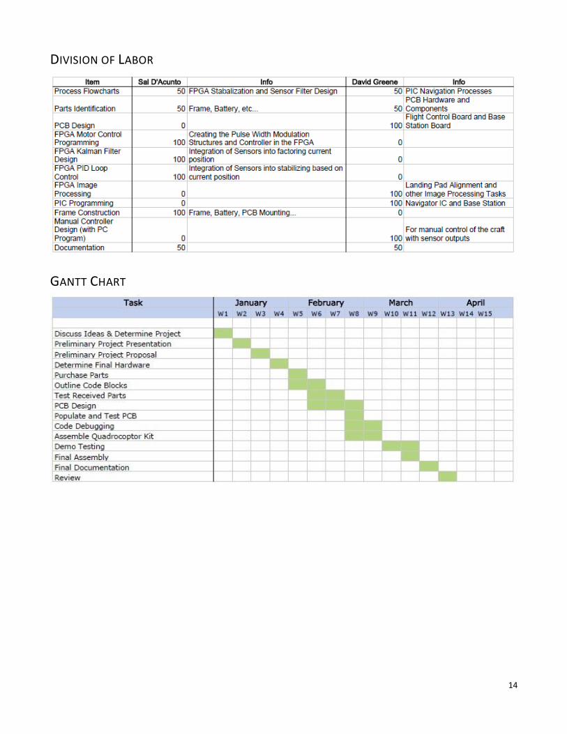
Division of Labor ........................................................................................................................................................................ 14
Gantt Chart ................................................................................................................................................................................ 14
Appendix .................................................................................................................................................................................... 15
Appendix A – Overview of the Flight Control Board ............................................................................................................. 15
Appendix B – Overview of the Base Station Board ............................................................................................................... 17

5
PRODUCT FEATURES/OBJECTIVES During specification, a series of requirements were placed to ensure adequate and safe operation of the craft.
1. A Manual Switch & Emergency Software Shutdown
a. The manual switch serves to ensure the craft will never engage when it is undesired. The manual
switch is placed in-series between the battery and the main power junction to the Electronic-
Speed-Controllers and the Fight Control Board
b. The Emergency Software Shutdown is a combination of two triggers: one if the device went
outside of radio communications range, and second a direct shutdown command that could be
activated if the device engaged in unwanted behavior.
2. Hover / Hold-Position
At a minimum, the device is required to engage in a mode where upon power-up, it will lift-off
approximately one foot and hold its position in air. This requirement would prove the
functionality of the stability controls implemented on the Flight Control Board.
3. Positional Sensing
By combining an 3-Axis accelerometer, gyroscope, and magnetometer, the Ad-Flier obtains a
highly accurate and reliable vector of its current orientation in space. Coupled with a barometer
to act as an altimeter, the device possesses all of the sensory inputs required to self-sustain itself
in air while supplied with power.
HARDWARE OVERVIEW
MECHANICAL OVERVIEW
FRAME X 525 Quadcopter frame was chosen to be the frame for the Quadcopter. The frame was made with a
fiberglass base and aluminum rods to support the plus configuration. The ends of the rods are attached
to mounts supported by springs that allow for softer landings. The fiberglass and hollow aluminum tubes
all the craft to be made lighter so smaller motors and a smaller battery can be used.
MOTORS Four XXD 2212 KV1000 brushless motors were used. These motors take an 11.1 V power supply from the
battery as well as the input signal from the ESC. The maximum efficiency of the motors was rated at 75%.
They also have a no load speed of 10800 rpm and a load speed of 5880 rpm. Each motor weighs
approximately 218g.
ESC In order to control the motors, HobbyWing Skywalker 20A 2A-BEC Brushless ESCs were used. An ESC is an
electronic servo controller. The ESC uses a 50 Hz PWM signal with a 1 to 2ms-pulse width to control the
motor between 0 and 100% output. The ESC’s had to be programmed using a programming card. This
allowed control over the timing mode, the startup mode, and the cut off voltage. The cut off voltage was
the most important parameter. If the battery reaches a certain low on the voltage the ESCs reduce the
speed of the motor slowly so the battery does not drain below a dangerous level and so the Quadcopter
doesn’t instantly shut off and crash.

6
FLIGHT CONTROL BOARD OVERVIEW
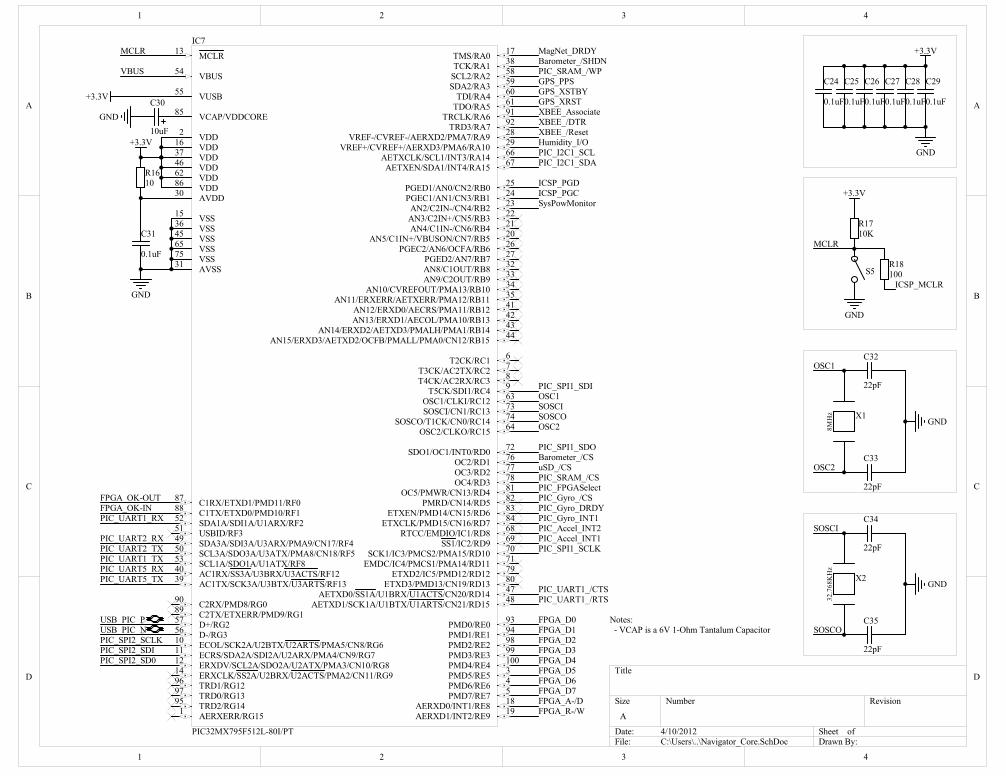
CORE COMPONENTS 1. PIC32MX795F512L 32-Bit Microcontroller
This device serves as the central math processing unit and communication hub of the craft. It
interfaces all of the long and short range communication systems, GPS sensors, and on-
board digital storage devices to the FPGA.
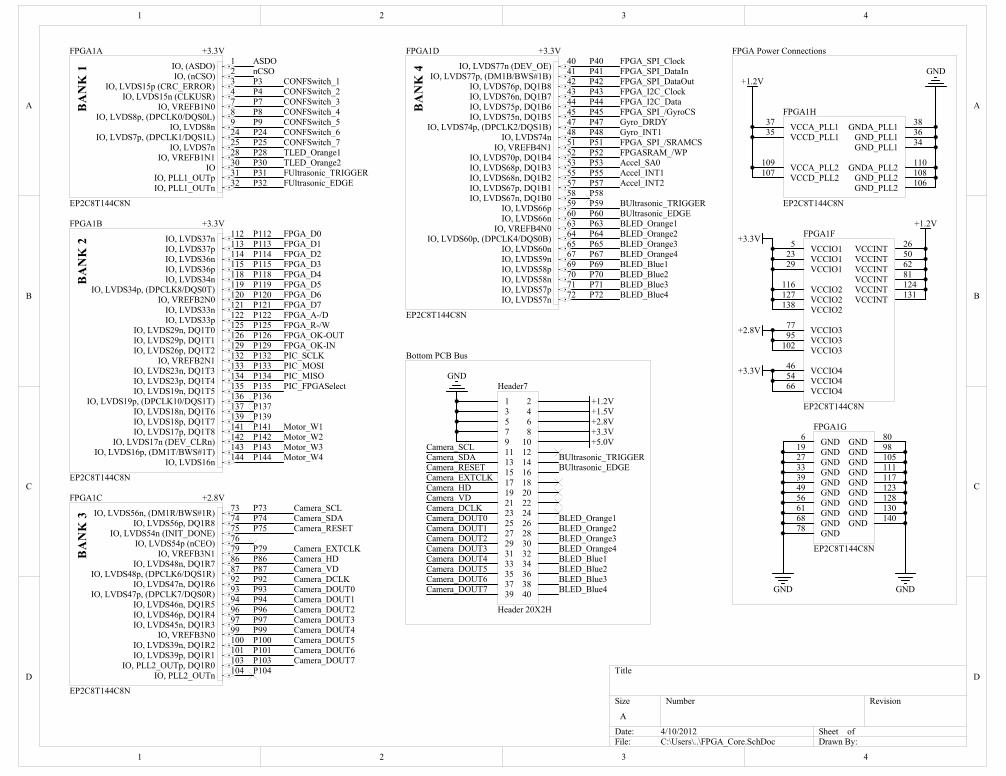
2. EP2C8T144C8N Cyclone II FPGA by Altera
This device served by providing the logic functions necessary for implementing the PID
controller and other stability control systems. It directly interfaced with the Electronic-
Speed-Controllers for the motors to regulate speed.
POSITION SENSORS 1. Accelerometer – This sensor gives us the approximate angle the device is relative to a point of gravity.
This position can change due to acceleration and would thus need another array of devices to
guarantee its position.
2. Gyroscope – This sensor delivers the approximate rotation of the craft in degrees per second. This
measurement is taken every 1/100th
of a second and reported to the stability control on the craft.
Since this sensor only gives you a rate of change measurement, it is coupled with the outputs of the
accelerometer and the magnetometer to provide a highly-accurate positional vector.
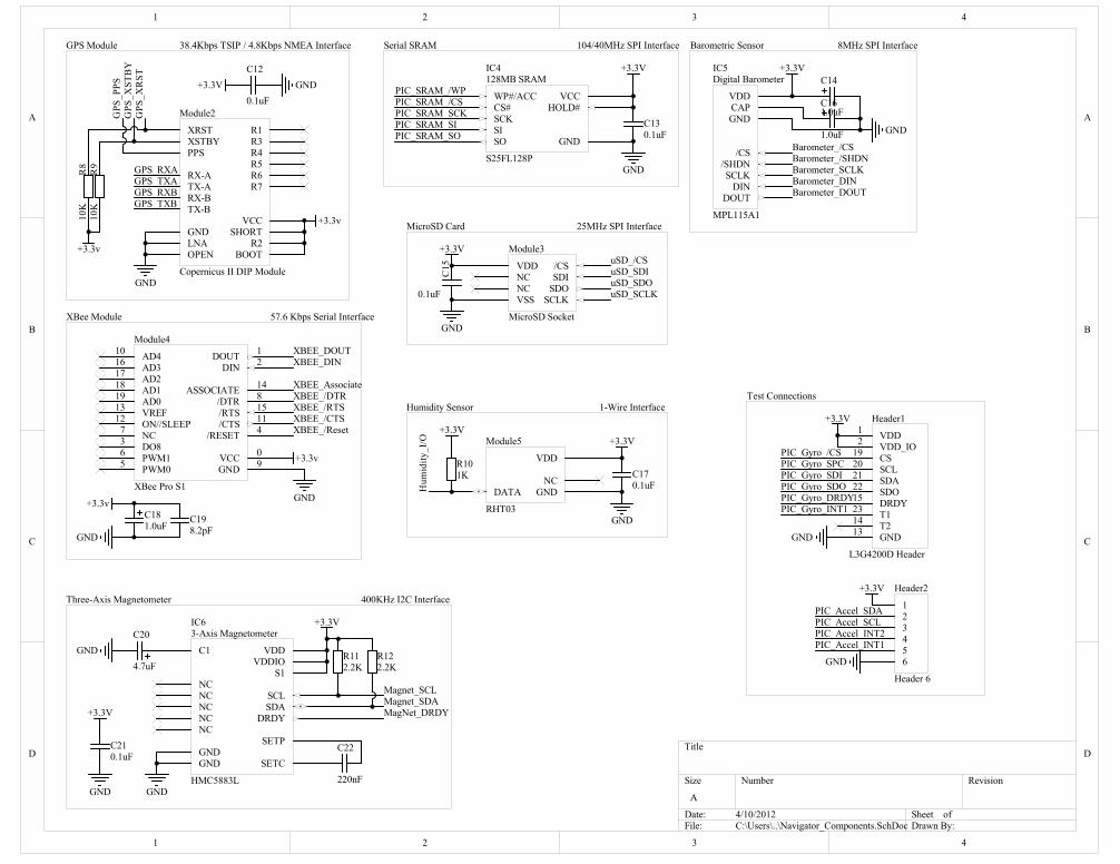
3. Magnetometer – Focusing in on the magnetic poles of the earth, this sensor acts as a digital compass,
delivering us a reading in Gauss of the largest magnetic field in the area. Since the motors often
would cause interruptions and disturbances with this sensor, the sensitivity was carefully calibrated
to average out the noise of the motors and still provide an accurate heading.
4. Barometer – This sensor provides the Flight Control Board with the relative pressure of its current
location. This value is incredibly useful in calculating height at large intervals and was thus used as an
altimeter when the ultrasonic sensors went out of range.

7
5. Humidity Sensor – The humidity sensor is a safety feature that will detect when the air surrounding
the device becomes too rich with moisture to ensure safe operations of the craft. Specific concerns
were related to moisture damaging operating circuits.
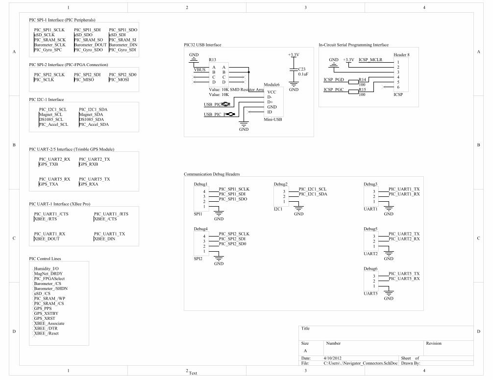
COMMUNICATION SYSTEM 1. The Flight Control Board is equipped with two means of communicating with the outside world. First,
a Full-Speed USB port is provided to interface with the PIC Microcontrollers as a virtual serial port.
This makes downloading information from the SD-Card or on-board Flash SRAM a snap.
2. The second, and main communication system, is the long-range XBee S1 Pro communication system.
This device is capable of transmitting and receiving data at 57.6Kbps at incredible ranges. The XBee’s
receiving module is connected to the Base Station, which will be later discussed.
ON-BOARD STORAGE 1. The primary storage medium is the MicroSD card slot connected to the PIC32 Microcontroller. It is
responsible for recording flight logs, sensor data, and to store photos from the camera board.
2. The Flight Control Board is also equipped with two 128MB Serial Flash SRAM chips; one connected to
the FPGA and the other connected to the PIC32. Each is capable at operating at speeds up to
104Mbps which was well within the operating clock speeds of both devices. The FLASH SRAM
modules were implemented to serve as short-term storage for data intensive mathematical processes
for the FPGA or PIC.
8
CAMERA BOARD OVERVIEW
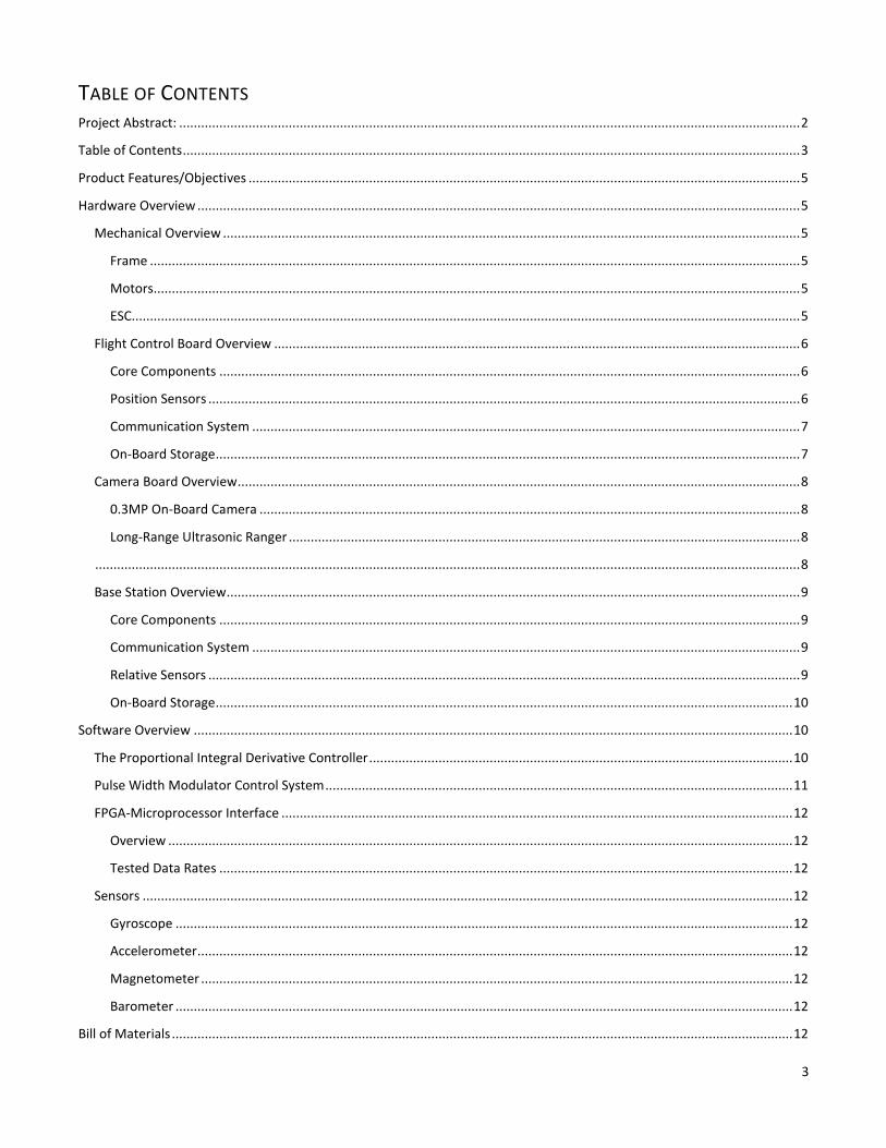
0.3MP ON-BOARD CAMERA The bottom camera is capable of capturing images at up to 640x480 pixel resolution and outputs
them in RGB format across a 50MHz databus. This is picked-up by the FPGA, processed, and
stored as an image on the MicroSD card. The camera module serves as a future implementation
of an automatic-landing mechanism, where an image will be taken and using image processing
techniques, the FPGA will attempt to locate and align with a target.
LONG-RANGE ULTRASONIC RANGER The Ad-Flier is equipped with two Ultrasonic rangefinders mounted on the top and bottom of the
craft. Each has an operational range of up to 150cm (59.055 ft.) and a measuring angle of 30.

9
BASE STATION OVERVIEW
CORE COMPONENTS PIC32MX795F512L 32-Bit Microcontroller
This device serves as a hub for all ground-to-air communications. It fans-out the data stream
coming from the Ad-Flier into several useable mediums and ensuring that the device is
behaving safely. Should the device act out of accordance with its programming, the base
station will have the ability to remotely terminate operations of the craft and either force an
immediate shutdown, or allow the craft to hover down to the ground.
COMMUNICATION SYSTEM 1. USB Full-Speed Virtual Serial Port – This allows for quick transfers of information form the PIC to a
connected PC. This also allows a future implementation of programming the PIC Microcontroller
directly from the USB port instead of requiring an additional programmer.
2. XBee Long-Range S1 Wireless Module – This device allowed incredibly long-range communications
with the Ad-Flier while in flight. Operating distance is reduced greatly when the craft is not in line-of-
sight.
3. Bluetooth Serial Interface – This module specifically serves the role of debug output and operational
commands to the craft from a connected PC. It is also designed to interface with the GUI Console to
display the Ad-Flier’s current position, heading, and other system information.
4. PlayStation II Wireless Remote Control – This module gives the user manual control of the craft and
allows them to enjoy the full limits of what it is capable of.
RELATIVE SENSORS
10
1. Barometer – The relative barometric pressure sensor is used to obtain the relatve pressure of ground.
This is used in the Ad-Flier’s height calculations as a basis. The barometer also features a built-in
thermometer.
2. Global Positioning System – The Base Station features a Trimble GPS system which provides it with its
current location. This allows the Ad-Flier to have an approximate location of where HOME is located
and where it should return when the battery voltage drops below the desired threshold.
ON-BOARD STORAGE 1. The primary storage medium is the MicroSD card slot connected to the PIC32 Microcontroller. It hold
flight logs, error reports, and other sensor data logs.
SOFTWARE OVERVIEW
THE PROPORTIONAL INTEGRAL DERIVATIVE CONTROLLER
In order to implement stabilization of the Quadcopter, several PID controllers were used. A PID controller, short
for proportional, integral, derivative, is a useful control loop feedback mechanism. The controller works by first
calculating an error. The error is the difference of the desired process variable and the measured process variable.
In our case, there were three PID controllers used to control the angles of the axes, pitch, roll, and yaw. There was
also one controller used to control altitude.
Pitch is the orientation for the machine with respect to the nose of the quad. A positive pitch degree indicates that
the nose is pointed up and the device will fly backwards. A negative pitch angle indicates that the noise is pointed
down and that the quad will fly forward. In our machine, positive pitch was a counterclockwise rotation in the
positive y-axis. Stabilization of pitch was controlled by offsets to the front and rear motors.
Roll is the orientation of the machine with respect to the wings. A positive roll degree indicates that the right wing
is higher and the quad will fly to the left. A negative roll angle indicates that the left wing is higher and the
machine will drift to the right. In our machine, positive pitch indicates a counterclockwise rotation in the positive
x-axis. Stabilization of pitch was controlled by offsets to the left and right motors.
Yaw is the orientation of the machine perpendicular to pitch and roll. In our machine this would be the z-axis. A
positive yaw rotation would be a clockwise rotation about the positive z-axis, where the positive z-axis is the axis
extending out of the top of the quad. Stabilization of yaw is controlled by increasing torque of either the front and
back motor or the left and right motor with respect to the other pair of motors. This stabilization is possible in the
quad because each pair of motors has either clockwise rotating props or counterclockwise rotating props. Each
pair tends to make the craft rotate in a different direction.
The altitude was how high off the ground the quad was. Adding or subtracting the same amount of torque to each
motor achieved stabilization of the altitude.
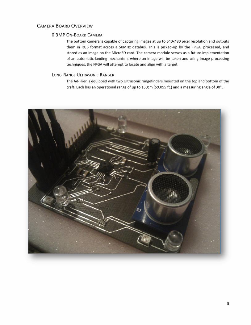
The inputs of the PID controllers were either angles or altitude and the outputs were all an 8 bit vector used in
conjunction with the PWM module to change the speed of the motors. A typical block diagram of a PID controller,
obtained from Wikipedia, can be seen in the figure below.
11
Block Diagram of a PID controller
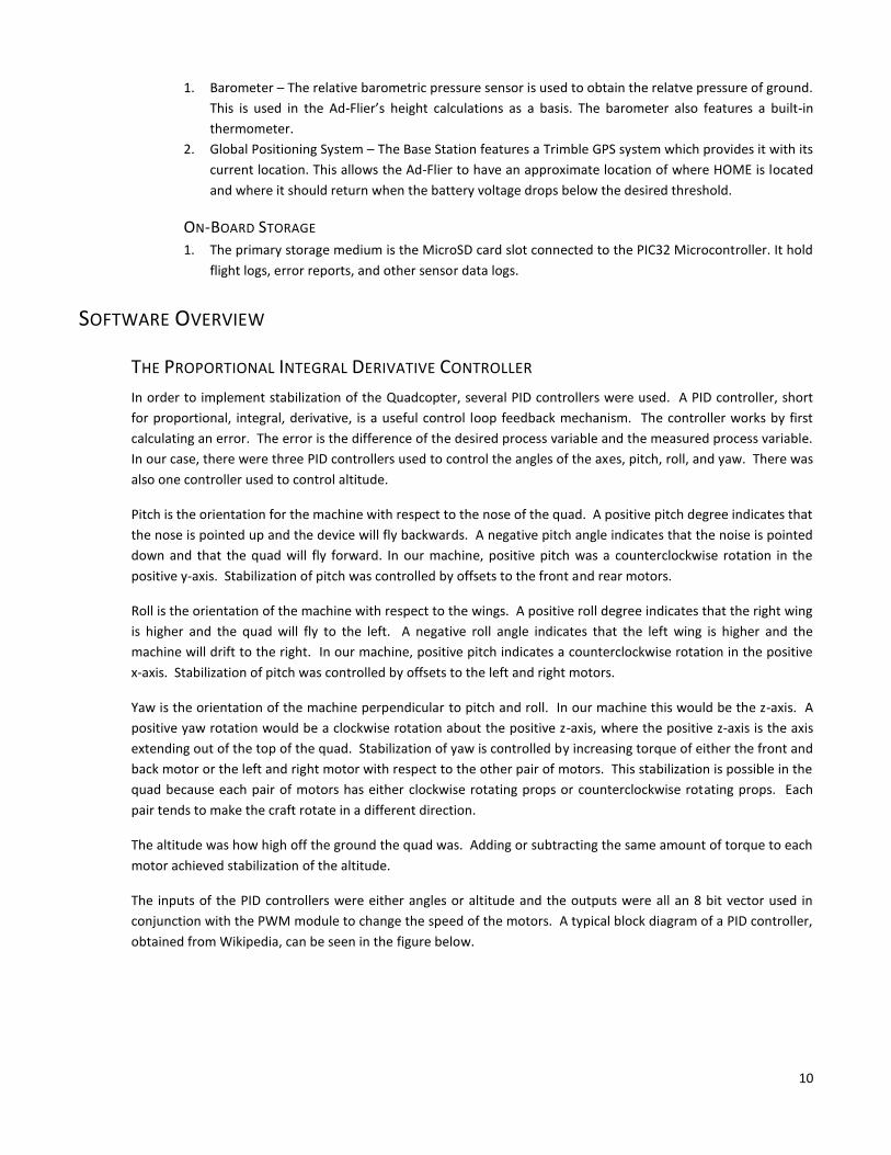
In order to create the PID controller in VHDL the equations had to be discretized. The equation of the discreet PID
controller is given as
This is known as the velocity form of the PID equation. The terms with K and T were replaced with KP, KI, and KD.
These are all constants that are separate for each separate controller. The constants are determined by tuning. In
the process of tuning, KI, and KD are set equal to zero while KP is increased until oscillation in the desired
controller output is achieved. Then KD is increased until the oscillations subside. Finally KI is increased until the
steady state time is achieved in an acceptable time.
Tuning the PID controller proved to be a daunting task. First, implementing the equations in VHDL had to be done
with integer math. This required a lot of changing of variables. Determining the limits for the PID controller was
also challenging. For the limits, it was determined that a 30-degree error in either direction would cause the
motor for the drooping side to operate at 80%. This greatly increases the speed before the quad flips over and
becomes uncontrollable. Also, while tuning for pitch and roll takes place separately, when combined the angles of
pitch and roll actually effect each other. This adds another level of complexity to the tuning process and makes
the results less desirable. Scaling down the integer values used in the PID in order to achieve an 8 bit values that
was actually proportional to the desired output was also a challenging task.
The PID controllers used can be seen in the code attachment.
PULSE WIDTH MODULATOR CONTROL SYSTEM
The PWM component was also composed in VHDL for use on the FPGA. The purpose of the PWM module was to
convert the output from the PID controllers to a useful signal that was capable of controlling the motors. As

12
mention above, the motors are driven by an ESC. The ESC takes an input PWM signal to control the motor. This
signal is composed of a 50 Hz frequency signal with varying pulse with for the duty cycle. The pulse width for the
ESC input ranges from 1ms to 2ms. A 1ms pulse indicates 0% of the motor power. A 2ms pulse indicates 100% of
the motor power.
The first step in the code was to create a 50 Hz signal from the 25.175 Mhz clock on the FPGA. Using a clock
divider did this. The next step was to make an input to the module create different pulse widths for the output.
The resolution of the PWM controller was 8 bits for a 1ms swing in output. This is .04% change in motor speed for
each count in the input vector.
The only problem with the control of the motors is that all motors are not created the same. Each motor required
a different offset value before it would actually turn on. This offset was accounted for by using the rangefinder to
make sure that each motor initialized for the same input value plus offset to the PWM unit.
FPGA-MICROPROCESSOR INTERFACE
OVERVIEW To allow communications between the PIC and FPGA, and allow the passing of nessecary data, a simple 8-
bit parallel port communications system was constructed between the two devices. Using a handshake
method, the PIC Microcontroller is able to either read a specified list of registers on the FPGA or write to a
list of specified registers on the FPGA.
TESTED DATA RATES
When a continuous read/write test was performed, the PIC was able to transfer at a rate of 2.66Mbps
SENSORS
GYROSCOPE The L3G4200D Gyroscope transfers 16-bit values across the SPI bus in 8-bit increments. It can achieve a
maximum rate of 10MHz when in SPI Mode.
ACCELEROMETER
MAGNETOMETER The HMC5883L Magnetometer communicates using the I2C line with rates up to 400KHz. The data is
stored as 12-Bit ADC readings and need proper conversion back to Gauss before they can be used.
BAROMETER The MPL115A1 Barometer communicates using the SPI bus at a max rate of 8 MHz Several iterations of
conversions are needed before the data outputted is usable. The pressure readings are also significantly
affected by the relative temperature and operating conditions.
BILL OF MATERIALS
Part Manufacturer Description
EP2C8T144C8N Altera Cyclone II FPGA
TCM8230MD Toshiba 640x480 Camera Module
TCM8230MD Toshiba 640x480 Camera Module
EP2C8T144C8N Altera Cyclone II FPGA
XBEE Pro S1 Digi International Long-Range Wireless

13
PIC32MX795F512L Microchip 32bit PIC Processor
Copernicus Trimble GPS Module
EPCS16SI8N Altera 16MB FPGA Configuration SRAM
SD Card EgoChina SD Card
RF-2400W Inhaos Short Range Wireless
S25FL128P Spansion 128MB 104MHz Flash Memory
HMC5883L Honeywell Magnetometer
RHT03 Maxdetect Humidity Sensor
SST26VF032 Silicon Storage Technologies 32MB Serial Quad I/O Flash
MCP2200 Microchip USB -> USART
HC-06 Itead Studio SMD Bluetooth Module
MMA8452Q Freescale Semiconductors Accelerometer
L3G4200D STMicroelectronics Gyroscope
MPL115A1 Freescale Semiconductors Pressure Sensor
DS1085 Maxim Semiconductors Programmable Clock Synthesizer
HC-SR04 Itead Studio Ultrasonic Ranger
14
DIVISION OF LABOR
GANTT CHART
15
APPENDIX
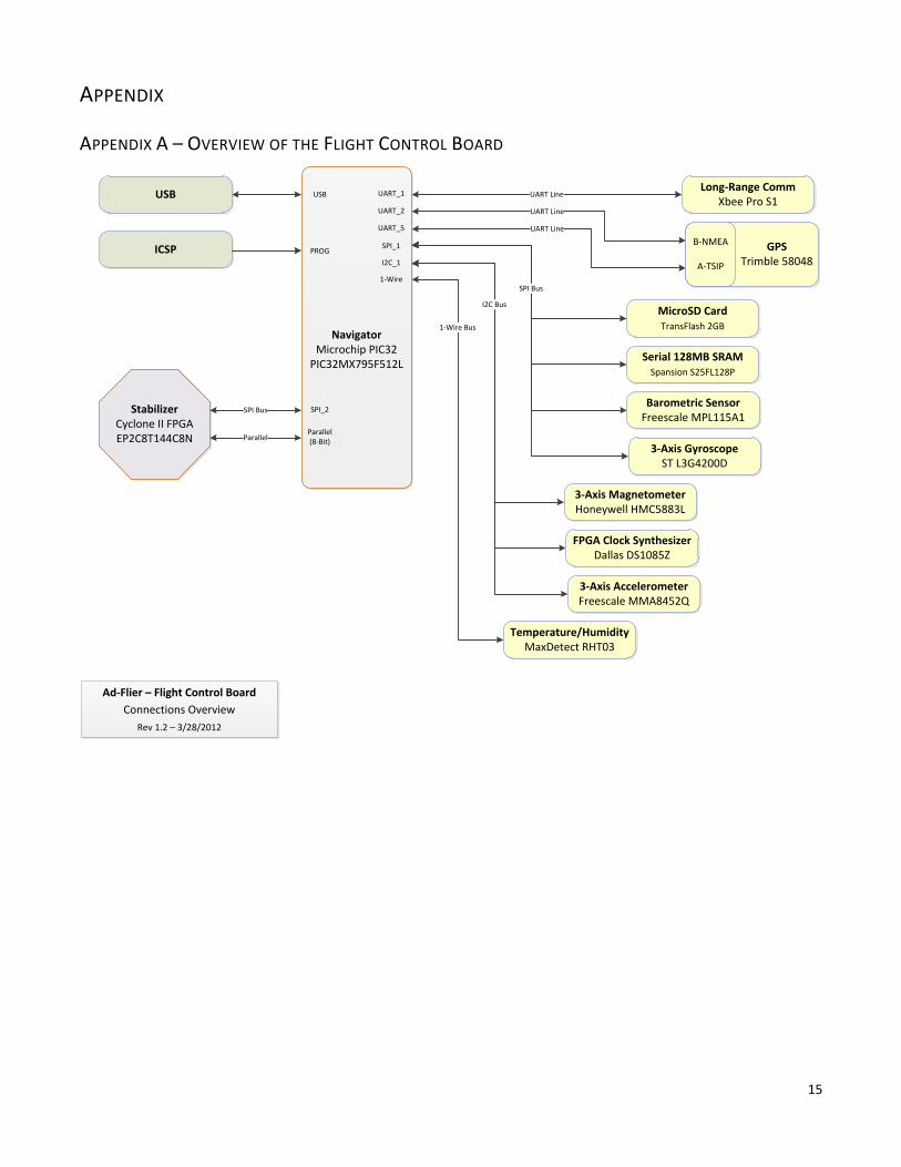
APPENDIX A – OVERVIEW OF THE FLIGHT CONTROL BOARD
Temperature/HumidityMaxDetect RHT03
Long-Range CommXbee Pro S1
StabilizerCyclone II FPGAEP2C8T144C8N
NavigatorMicrochip PIC32
PIC32MX795F512L
USB
ICSP
SPI Bus
Parallel
UART Line
MicroSD CardTransFlash 2GB
Serial 128MB SRAMSpansion S25FL128P
3-Axis MagnetometerHoneywell HMC5883L
Barometric SensorFreescale MPL115A1
3-Axis AccelerometerFreescale MMA8452Q
3-Axis GyroscopeST L3G4200D
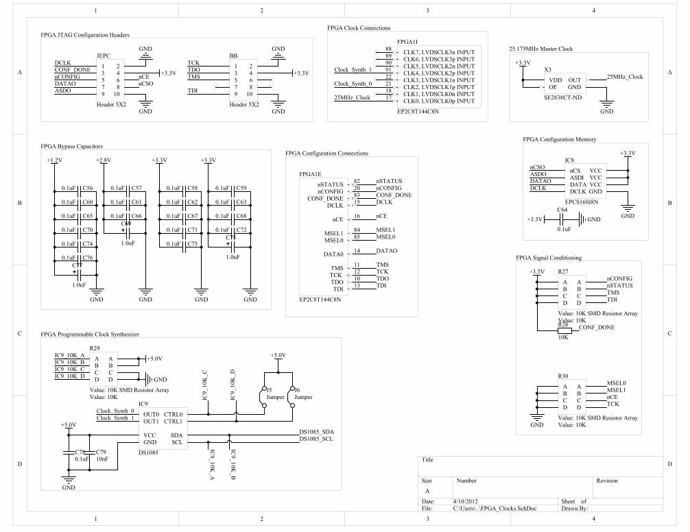
FPGA Clock SynthesizerDallas DS1085Z
UART Line
UART Line
SPI Bus
I2C Bus
1-Wire Bus
UART_1
UART_2
UART_5
SPI_1
I2C_1
1-Wire
USB
PROG
SPI_2
Parallel (8-Bit)
GPS Trimble 58048
B-NMEA
A-TSIP
Ad-Flier – Flight Control Board
Connections Overview
Rev 1.2 – 3/28/2012

16
Power Requirements
USART
SPI
I2C
I2CSPI
SPI
USART
SPI ISP
I2C
I2C / SPI
Parallel
PWM
PWM
PWM
PWM
StabilizerAltera Cyclone IIEP2C8T144C8N
MicroSD CardTransFlash 2GB
Barometric SensorFreescale MPL115A1
3-Axis MagnetometerHoneywell HMC5883L
Motor Controller 4
Motor Controller 3
3-Axis GyroscopeST Micro L3G4200D
3-Axis AccelerometerFreescale MMA8452
Ultrasonic RangefinderiTead Studio HC-SR04
Temperature/HumidityMaxDetect RHT03
GPS NavigationTrimble 58048-20
Flight/Landing CameraToshiba SEN-08667
Motor Controller 2
Motor Controller 1
FPGA ConfigEPCS4SI8N 16MB
Par
alle
l I/O
Bu
s
NavigatorMicrochip PIC32
PIC32MX795F512L
Long-Range CommXbee Pro S1
Programmable Clock Synthesizer DS1085
+2.8 / +1.5 V
+3.3 / +1.2 VDC
+5.0 VDC
+3.3 VDC
The Ad-Flier!Team Sky Lights
- - -Flight Control Board
Serial SRAMSpansion 128MB Flash
Serial SRAMSST 32MB
17
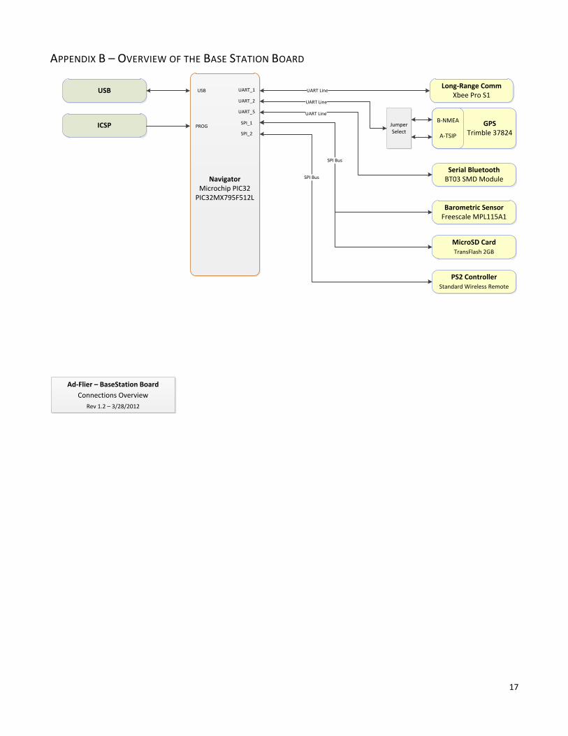
APPENDIX B – OVERVIEW OF THE BASE STATION BOARD
Long-Range CommXbee Pro S1
NavigatorMicrochip PIC32
PIC32MX795F512L
USB
ICSP
UART Line
Barometric SensorFreescale MPL115A1
UART Line
SPI Bus
SPI Bus
UART_1
UART_2
UART_5
SPI_1
SPI_2
USB
PROG GPS Trimble 37824
B-NMEA
A-TSIP
Ad-Flier – BaseStation Board
Connections Overview
Rev 1.2 – 3/28/2012
Serial BluetoothBT03 SMD Module
PS2 ControllerStandard Wireless Remote
JumperSelect
MicroSD CardTransFlash 2GB
UART Line
18
Parallel
Wireless Manual Control
USART
SPISPI
SPI
USART
MicroSD CardTransFlash 2GB
Serial SRAMSST 32MB
Barometric & Temperature SensorFreescale MPL115A1
GPS NavigationTrimble 58048-20
Long-Range CommXbee Pro S1
Bluetooth SerialSerial Bluetooth Module
USART USART
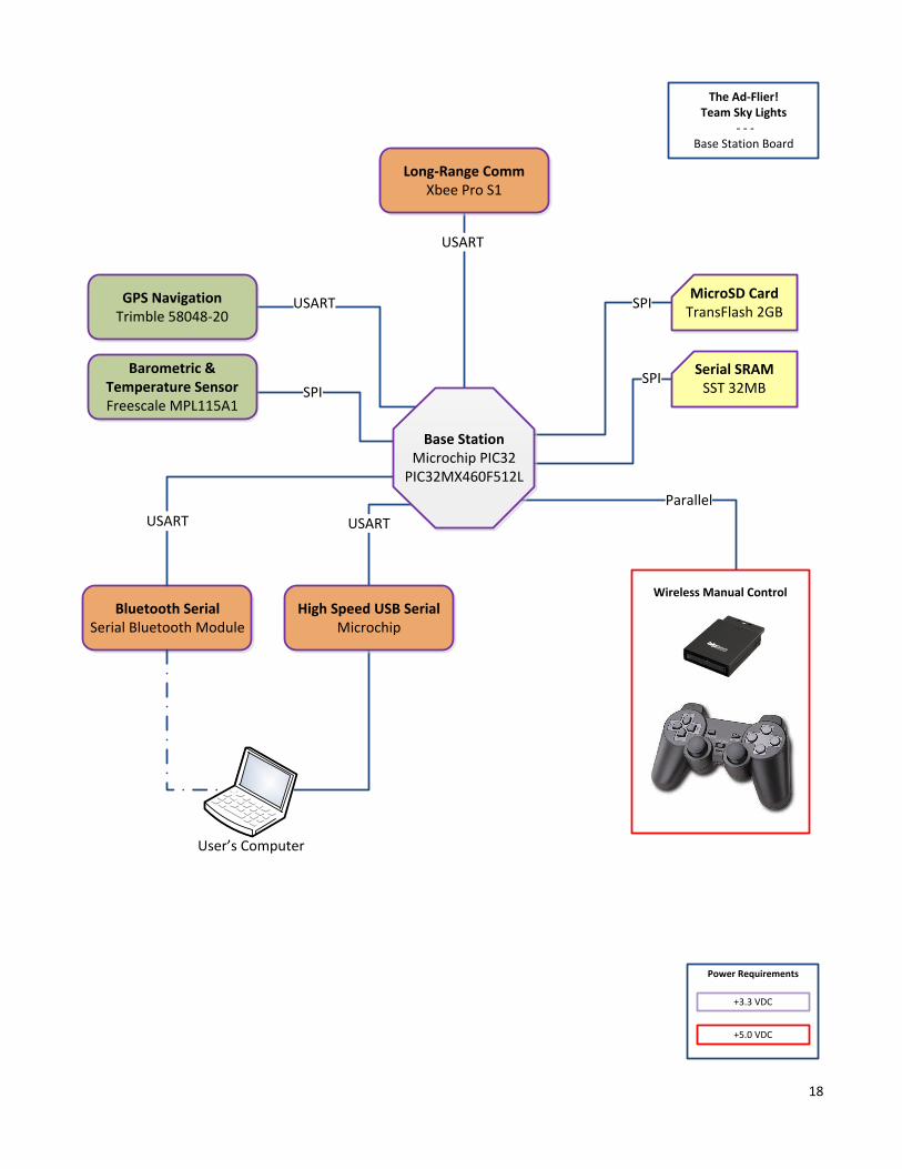
Base StationMicrochip PIC32
PIC32MX460F512L
User’s Computer
High Speed USB SerialMicrochip
Power Requirements
+5.0 VDC
+3.3 VDC
The Ad-Flier!Team Sky Lights
- - - Base Station Board

1
1
2
2
3
3
4
4
D D
C C
B B
A A
Title
Number RevisionSize
A
Date: 4/10/2012 Sheet ofFile: C:\Users\..\Power.SchDoc Drawn By:
MIC5330-MFYML
VIN
GND
BYP
EN2EN1
VOUT2
VOUT1 +2.8V
+1.5V
REG1
MIC5330-MFYML
VIN
GN
D
VOUT
MIC29300-5.0WU+5.0V
REG2
MIC49300-1.2WU+1.2V
EN
VBIAS
GN
D
VIN VOUT
REG3
0.1uFC43
0.1uFC38
0.1uFC40
GND
GND
GND
GND
SYS
SYS +5.0V +2.8V
+1.5V
+1.2V
+5.0V
+5.0V
VIN
GN
D
VOUT
MIC29300-3.3WU+3.3V
REG4
0.1uFC49
GND
SYS +3.3V
+6
to
+1
1.7
VD
C
+5.0 VDC
5.0 -> 2.8 & 1.5 VDC
5.0 -> 1.2 VDC
Battery -> 3.3 VDC
Battery -> 5.0 VDC
3S Lipo Battery
+5.0V Rated: 3000mA +3.3V Rated: 3000mA +2.8V Rated: 150mA +1.5V Rated: 150mA +1.2V Rated: 3000mA
Power Rails:
1.0uFC36
10uFC37
SYS
1.3KR20
3.9K
R19
D21SMAS913BT3G
D1
MBRS540T3G
D3
MBRS540T3G
GND
GND
GND
SysPowMonitor
Power Input, Selection, and Monitoring
+3.3V
1K
R21
GND
1
1.0uFC39
1.0uFC42
1.0uFC44
1.0uF
C45
1.0uFC48
10uFC41
10uFC46
10uFC47
VDDGND
Header9
Battery Conn
LED3
VCCGND
H1
DC Jack
PIC3601
PIC3602COC36 PIC3701
PIC3702COC37
PIC3801
PIC3802COC38
PIC3901
PIC3902COC39
PIC4001
PIC4002COC40PIC4101
PIC4102COC41 PIC4201
PIC4202COC42PIC4301
PIC4302COC43
PIC4401
PIC4402COC44
PIC4501PIC4502
COC45
PIC4601
PIC4602COC46
PIC4701
PIC4702COC47 PIC4801
PIC4802COC48
PIC4901
PIC4902COC49
PID100PID101
COD1
PID200PID201 COD2
PID300PID301
COD3
PIH10GND
PIH10VCC
COH1
PIHeader90L
PIHeader90R
COHeader9
PILED301 PILED302
COLED3
PIR1901PIR1902
COR19
PIR2001
PIR2002COR20
PIR2101PIR2102COR21
PIREG100
PIREG101
PIREG102
PIREG103
PIREG104
PIREG106
PIREG107
COREG1
PIREG200
PIREG201
PIREG202
COREG2
PIREG300
PIREG301
PIREG302
PIREG303 PIREG304
COREG3
PIREG400
PIREG401
PIREG402
COREG4
PIC4601PIREG304
PIC4401PIREG106
PIC4201PIREG107
PIC4701
PIR2102
PIREG402
PIC3901PIC4101
PIC4501
PIC4801
PIREG100
PIREG103
PIREG104PIREG202
PIREG300
PIREG301
PIREG303
PIC3602 PIC3702PIC3801
PIC3902 PIC4001PIC4102 PIC4202PIC4302
PIC4402
PIC4502
PIC4602
PIC4702 PIC4802PIC4901
PID200PIH10GND
PIHeader90R
PILED302
PIR2001
PIREG101
PIREG201
PIREG302PIREG401
PIC4002PIREG102
PID100PIHeader90L
PID300PIH10VCC
PILED301PIR2101
PIC3601 PIC3701PIC3802
PIC4301
PIC4902
PID101
PID301
PIR1902
PIREG200
PIREG400
PID201PIR1901
PIR2002
NLSysPowMonitor
1
1
2
2
3
3
4
4
D D
C C
B B
A A
Title
Number RevisionSize
A
Date: 4/10/2012 Sheet ofFile: C:\Users\..\Navigator_Core.SchDoc Drawn By:
TMS/RA0 17
TCK/RA1 38
SCL2/RA2 58
SDA2/RA3 59
TDI/RA4 60
TDO/RA5 61
TRCLK/RA6 91
TRD3/RA7 92
VREF-/CVREF-/AERXD2/PMA7/RA9 28
VREF+/CVREF+/AERXD3/PMA6/RA10 29
AETXCLK/SCL1/INT3/RA14 66
AETXEN/SDA1/INT4/RA15 67
PGED1/AN0/CN2/RB0 25
PGEC1/AN1/CN3/RB1 24
AN2/C2IN-/CN4/RB2 23
AN3/C2IN+/CN5/RB3 22
AN4/C1IN-/CN6/RB4 21
AN5/C1IN+/VBUSON/CN7/RB5 20
PGEC2/AN6/OCFA/RB6 26
PGED2/AN7/RB7 27
AN8/C1OUT/RB8 32
AN9/C2OUT/RB9 33
AN10/CVREFOUT/PMA13/RB10 34
AN11/ERXERR/AETXERR/PMA12/RB11 35
AN12/ERXD0/AECRS/PMA11/RB12 41
AN13/ERXD1/AECOL/PMA10/RB13 42
AN14/ERXD2/AETXD3/PMALH/PMA1/RB14 43
AN15/ERXD3/AETXD2/OCFB/PMALL/PMA0/CN12/RB15 44
T2CK/RC1 6
T3CK/AC2TX/RC2 7
T4CK/AC2RX/RC3 8
T5CK/SDI1/RC4 9
OSC1/CLKI/RC12 63
SOSCI/CN1/RC13 73
SOSCO/T1CK/CN0/RC14 74
OSC2/CLKO/RC15 64
SDO1/OC1/INT0/RD0 72
OC2/RD1 76
OC3/RD2 77
OC4/RD3 78
OC5/PMWR/CN13/RD4 81
PMRD/CN14/RD5 82
ETXEN/PMD14/CN15/RD6 83
ETXCLK/PMD15/CN16/RD7 84
RTCC/EMDIO/IC1/RD8 68
SS1/IC2/RD9 69
SCK1/IC3/PMCS2/PMA15/RD10 70
EMDC/IC4/PMCS1/PMA14/RD11 71
ETXD2/IC5/PMD12/RD12 79
ETXD3/PMD13/CN19/RD13 80
AETXD0/SS1A/U1BRX/U1ACTS/CN20/RD14 47
AETXD1/SCK1A/U1BTX/U1ARTS/CN21/RD15 48
PMD0/RE0 93
PMD1/RE1 94
PMD2/RE2 98
PMD3/RE3 99
PMD4/RE4 100
PMD5/RE5 3
PMD6/RE6 4
PMD7/RE7 5
AERXD0/INT1/RE8 18
AERXD1/INT2/RE9 19
C1RX/ETXD1/PMD11/RF087
C1TX/ETXD0/PMD10/RF188
SDA1A/SDI1A/U1ARX/RF252
USBID/RF351
SDA3A/SDI3A/U3ARX/PMA9/CN17/RF449
SCL3A/SDO3A/U3ATX/PMA8/CN18/RF550
VUSB55
VBUS54
SCL1A/SDO1A/U1ATX/RF853
AC1RX/SS3A/U3BRX/U3ACTS/RF1240
AC1TX/SCK3A/U3BTX/U3ARTS/RF1339
C2RX/PMD8/RG090
C2TX/ETXERR/PMD9/RG189
D+/RG257
D-/RG356
ECOL/SCK2A/U2BTX/U2ARTS/PMA5/CN8/RG610
ECRS/SDA2A/SDI2A/U2ARX/PMA4/CN9/RG711
ERXDV/SCL2A/SDO2A/U2ATX/PMA3/CN10/RG812
ERXCLK/SS2A/U2BRX/U2ACTS/PMA2/CN11/RG914
TRD1/RG1296
TRD0/RG1397
TRD2/RG1495
AERXERR/RG151
MCLR13
VDD86
VCAP/VDDCORE85
VDD2
VDD16
VDD37
VDD46
VDD62
AVDD30
AVSS31
VSS15
VSS36
VSS45
VSS65
VSS75
IC7
PIC32MX795F512L-80I/PT
GND
10R16
+3.3V
GND
Notes: - VCAP is a 6V 1-Ohm Tantalum Capacitor
SysPowMonitor
MCLR
VBUS
USB_PIC_NUSB_PIC_P
OSC1
OSC2
ICSP_PGDICSP_PGC
SOSCISOSCO
FPGA_D0FPGA_D1FPGA_D2FPGA_D3FPGA_D4FPGA_D5FPGA_D6FPGA_D7FPGA_A-/DFPGA_R-/W
FPGA_OK-OUTFPGA_OK-IN
PIC_I2C1_SCLPIC_I2C1_SDA
PIC_UART1_/CTSPIC_UART1_/RTS
PIC_UART1_RX
PIC_UART1_TXPIC_UART5_RXPIC_UART5_TX
PIC_UART2_RXPIC_UART2_TX PIC_SPI1_SCLK
PIC_SPI1_SDI
PIC_SPI1_SDO
PIC_SPI2_SCLKPIC_SPI2_SDIPIC_SPI2_SD0
MagNet_DRDY
Humidity_I/O
PIC_FPGASelect
PIC_SRAM_/WP
PIC_SRAM_/CSuSD_/CSBarometer_/CS
Barometer_/SHDN
GPS_XRSTGPS_XSTBYGPS_PPS
XBEE_AssociateXBEE_/DTRXBEE_/Reset
22pF
C34
GND
22pF
C35
SOSCI
SOSCO
32.7
68K
Hz
X2
22pF
C32
GND
8MH
z X1
22pF
C33
OSC1
OSC2
10KR17
100R18
+3.3V
MCLR
ICSP_MCLRS5
GND
0.1uF
C29
+3.3V
GND
0.1uF
C28
0.1uF
C27
0.1uF
C26
0.1uF
C25
0.1uF
C31
0.1uF
C24
10uF
C30+3.3V
PIC_Accel_INT2PIC_Accel_INT1
PIC_Gyro_/CSPIC_Gyro_DRDYPIC_Gyro_INT1
PIC2401
PIC2402
COC24 PIC2501
PIC2502
COC25 PIC2601
PIC2602
COC26 PIC2701
PIC2702
COC27 PIC2801
PIC2802
COC28 PIC2901
PIC2902
COC29
PIC3001PIC3002
COC30
PIC3101
PIC3102
COC31
PIC3201PIC3202
COC32
PIC3301PIC3302
COC33
PIC3401PIC3402
COC34
PIC3501PIC3502
COC35
PIIC701
PIIC702
PIIC703
PIIC704
PIIC705
PIIC706
PIIC707
PIIC708
PIIC709
PIIC7010
PIIC7011
PIIC7012
PIIC7013
PIIC7014
PIIC7015
PIIC7016
PIIC7017
PIIC7018
PIIC7019
PIIC7020
PIIC7021
PIIC7022
PIIC7023
PIIC7024
PIIC7025
PIIC7026
PIIC7027
PIIC7028
PIIC7029
PIIC7030
PIIC7031 PIIC7032
PIIC7033
PIIC7034
PIIC7035
PIIC7036
PIIC7037
PIIC7038
PIIC7039
PIIC7040
PIIC7041
PIIC7042
PIIC7043
PIIC7044
PIIC7045
PIIC7046
PIIC7047
PIIC7048
PIIC7049
PIIC7050
PIIC7051
PIIC7052
PIIC7053
PIIC7054
PIIC7055
PIIC7056
PIIC7057
PIIC7058
PIIC7059
PIIC7060
PIIC7061
PIIC7062
PIIC7063
PIIC7064
PIIC7065
PIIC7066
PIIC7067
PIIC7068
PIIC7069
PIIC7070
PIIC7071
PIIC7072
PIIC7073
PIIC7074
PIIC7075
PIIC7076
PIIC7077
PIIC7078
PIIC7079
PIIC7080
PIIC7081
PIIC7082
PIIC7083
PIIC7084
PIIC7085
PIIC7086
PIIC7087
PIIC7088
PIIC7089
PIIC7090
PIIC7091
PIIC7092
PIIC7093
PIIC7094
PIIC7095
PIIC7096
PIIC7097
PIIC7098
PIIC7099
PIIC70100
COIC7
PIR1601
PIR1602COR16
PIR1701
PIR1702COR17
PIR1801
PIR1802
COR18
PIS501
PIS502COS5
PIX100
PIX101COX1
PIX200
PIX201
COX2
PIC2401 PIC2501 PIC2601 PIC2701 PIC2801 PIC2901
PIIC702
PIIC7016
PIIC7037
PIIC7046
PIIC7055
PIIC7062
PIIC7086
PIR1602
PIR1702
PIIC7076NLBarometer00CS
PIIC7038NLBarometer00SHDN
PIIC7018NLFPGA0A00D
PIIC7093NLFPGA0D0
PIIC7094NLFPGA0D1
PIIC7098NLFPGA0D2
PIIC7099NLFPGA0D3
PIIC70100NLFPGA0D4
PIIC703NLFPGA0D5
PIIC704NLFPGA0D6
PIIC705NLFPGA0D7
PIIC7088NLFPGA0OK0IN
PIIC7087NLFPGA0OK0OUT
PIIC7019NLFPGA0R00W
PIC2402 PIC2502 PIC2602 PIC2702 PIC2802 PIC2902PIC3002
PIC3102
PIC3201
PIC3301
PIC3401
PIC3501
PIIC7015
PIIC7031
PIIC7036
PIIC7045
PIIC7065
PIIC7075
PIS501
PIIC7059NLGPS0PPS
PIIC7061NLGPS0XRST
PIIC7060NLGPS0XSTBY
PIIC7029NLHumidity0I0O
PIR1802 NLICSP0MCLR
PIIC7024NLICSP0PGC
PIIC7025NLICSP0PGD
PIIC7017NLMagNet0DRDY
PIIC7013
PIR1701PIR1801PIS502
NLMCLR
PIC3001PIIC7085
PIC3101
PIIC7030PIR1601
PIIC701
PIIC706
PIIC707
PIIC708
PIIC7014
PIIC7020
PIIC7021
PIIC7022
PIIC7026
PIIC7027
PIIC7032
PIIC7033
PIIC7034
PIIC7035
PIIC7041
PIIC7042
PIIC7043
PIIC7044
PIIC7051
PIIC7071
PIIC7079
PIIC7080
PIIC7089
PIIC7090
PIIC7095
PIIC7096
PIIC7097
PIC3202
PIIC7063
PIX101NLOSC1
PIC3302
PIIC7064
PIX100NLOSC2
PIIC7069NLPIC0Accel0INT1
PIIC7068NLPIC0Accel0INT2
PIIC7081NLPIC0FPGASelect
PIIC7082NLPIC0Gyro00CS
PIIC7083NLPIC0Gyro0DRDY
PIIC7084NLPIC0Gyro0INT1
PIIC7066NLPIC0I2C10SCL
PIIC7067NLPIC0I2C10SDA
PIIC7070NLPIC0SPI10SCLK
PIIC709NLPIC0SPI10SDI
PIIC7072NLPIC0SPI10SDO
PIIC7010NLPIC0SPI20SCLK
PIIC7012NLPIC0SPI20SD0
PIIC7011NLPIC0SPI20SDI
PIIC7078NLPIC0SRAM00CS
PIIC7058NLPIC0SRAM00WP
PIIC7047NLPIC0UART100CTS
PIIC7048NLPIC0UART100RTS
PIIC7052NLPIC0UART10RX
PIIC7053NLPIC0UART10TX
PIIC7049NLPIC0UART20RX
PIIC7050NLPIC0UART20TX
PIIC7040NLPIC0UART50RX
PIIC7039NLPIC0UART50TX
PIC3402
PIIC7073
PIX200NLSOSCI
PIC3502
PIIC7074
PIX201NLSOSCO
PIIC7023NLSysPowMonitor
PIIC7056NLUSB0PIC0N
PIIC7057NLUSB0PIC0P
PIIC7077NLuSD00CS
PIIC7054NLVBUS
PIIC7092NLXBEE00DTR
PIIC7028NLXBEE00Reset
PIIC7091NLXBEE0Associate
1
1
2
2
3
3
4
4
D D
C C
B B
A A
Title
Number RevisionSize
A
Date: 4/10/2012 Sheet ofFile: C:\Users\..\Navigator_Connectors.SchDoc Drawn By:
PIC32 USB Interface In-Circuit Serial Programming Interface
DS1085_SDADS1085_SCLMagnet_SCL Magnet_SDAPIC_I2C1_SCL PIC_I2C1_SDA
PIC_SCLK PIC_MOSIPIC_MISOPIC_SPI2_SCLK PIC_SPI2_SDI PIC_SPI2_SD0
PIC_SRAM_SCK PIC_SRAM_SIPIC_SRAM_SOuSD_SDIuSD_SDOuSD_SCLK
PIC_SPI1_SCLK PIC_SPI1_SDI PIC_SPI1_SDO
Barometer_SCLK Barometer_DINBarometer_DOUT
PIC_UART1_/CTS PIC_UART1_/RTS
PIC_UART1_RX PIC_UART1_TX
GPS_RXAGPS_TXA
GPS_RXBGPS_TXB
XBEE_DOUT XBEE_DIN
XBEE_/RTS XBEE_/CTS
PIC_UART5_RX PIC_UART5_TX
PIC_UART2_RX PIC_UART2_TX
MagNet_DRDYHumidity_I/O
PIC_FPGASelect
PIC_SRAM_/WPPIC_SRAM_/CS
uSD_/CS
Barometer_/CSBarometer_/SHDN
GPS_XRSTGPS_XSTBYGPS_PPS
XBEE_AssociateXBEE_/DTRXBEE_/Reset
VBUS
GND +3.3V
0.1uFC23
GND
GND
USB_PIC_N
USB_PIC_P
ICSP_MCLR
ICSP_PGD
ICSP_PGC
+3.3VGND 123456
Header 8
ICSP
100R14
100R15
Value: 10K
ABCD
ABCD
R13
Value: 10K SMD Resistor Array
GNDID
D+D-VCC
Module6
Mini-USB
123
Debug2
I2C1
123
Debug3
UART1
123
Debug5
UART2
123
Debug6
UART5
1234
Debug1
SPI1
1234
Debug4
SPI2
PIC_SPI1_SCLKPIC_SPI1_SDIPIC_SPI1_SDO
GND
PIC_SPI2_SCLKPIC_SPI2_SDIPIC_SPI2_SD0
GND
PIC_I2C1_SCLPIC_I2C1_SDA
GND
PIC_UART2_TXPIC_UART2_RX
GND
PIC_UART1_RXPIC_UART1_TX
GND
PIC_UART5_RXPIC_UART5_TX
GND
Communication Debug Headers
PIC SPI-1 Interface (PIC Peripherals)
PIC SPI-2 Interface (PIC-FPGA Connection)
PIC I2C-1 Interface
PIC UART-2/5 Interface (Trimble GPS Module)
PIC UART-1 Interface (XBee Pro)
PIC Control Lines
Text
PIC_Accel_SDAPIC_Accel_SCL
PIC_Gyro_SPC PIC_Gyro_SDO PIC_Gyro_SDI
PIC2301
PIC2302COC23
PIDebug101
PIDebug102
PIDebug103
PIDebug104
CODebug1
PIDebug201
PIDebug202
PIDebug203
CODebug2
PIDebug301
PIDebug302
PIDebug303
CODebug3
PIDebug401
PIDebug402
PIDebug403
PIDebug404
CODebug4
PIDebug501
PIDebug502
PIDebug503
CODebug5
PIDebug601
PIDebug602
PIDebug603
CODebug6
PIHeader 801
PIHeader 802
PIHeader 803
PIHeader 804
PIHeader 805
PIHeader 806
COHeader 8
PIModule600
PIModule601
PIModule602
PIModule603
PIModule604
COModule6
PIR1301
PIR1302
PIR1303
PIR1304
PIR1305
PIR1306
PIR1307
PIR1308
COR13
PIR1401PIR1402COR14
PIR1501PIR1502COR15
PIC2302PIHeader 802
NLBarometer00CSNLBarometer00SHDN
PIDebug102
NLBarometer0DINNLPIC0Gyro0SDI
NLPIC0SPI10SDO
NLPIC0SRAM0SINLuSD0SDI
PIDebug103
NLBarometer0DOUTNLPIC0Gyro0SDO
NLPIC0SPI10SDI
NLPIC0SRAM0SONLuSD0SDO
PIDebug104
NLBarometer0SCLKNLPIC0Gyro0SPC
NLPIC0SPI10SCLK
NLPIC0SRAM0SCKNLuSD0SCLK
PIDebug203
NLDS10850SCLNLMagnet0SCL
NLPIC0Accel0SCL
NLPIC0I2C10SCL
PIDebug202
NLDS10850SDANLMagnet0SDA
NLPIC0Accel0SDA
NLPIC0I2C10SDA
PIC2301
PIDebug101
PIDebug201 PIDebug301
PIDebug401
PIDebug501
PIDebug601
PIHeader 803
PIModule600
PIR1305
NLGPS0PPS
PIDebug603
NLGPS0RXANLPIC0UART50TX
PIDebug503
NLGPS0RXBNLPIC0UART20TX
PIDebug602
NLGPS0TXANLPIC0UART50RX
PIDebug502
NLGPS0TXBNLPIC0UART20RX
NLGPS0XRSTNLGPS0XSTBY
NLHumidity0I0O
PIHeader 801NLICSP0MCLR
PIR1502NLICSP0PGC
PIR1402NLICSP0PGD
NLMagNet0DRDY
PIHeader 804
PIR1401 PIHeader 805
PIR1501
PIHeader 806
PIModule601
PIModule604
PIR1301
PIR1302
PIR1303
PIR1304
PIR1307
PIR1308
NLPIC0FPGASelect
PIDebug403
NLPIC0MISONLPIC0SPI20SDI
PIDebug402
NLPIC0MOSINLPIC0SPI20SD0
PIDebug404
NLPIC0SCLKNLPIC0SPI20SCLK
NLPIC0SRAM00CSNLPIC0SRAM00WP
NLPIC0UART100CTSNLXBEE00RTS
NLPIC0UART100RTSNLXBEE00CTS
PIDebug302
NLPIC0UART10RXNLXBEE0DOUT
PIDebug303
NLPIC0UART10TXNLXBEE0DIN
PIModule603
NLUSB0PIC0NPIModule602
NLUSB0PIC0P
NLuSD00CS
PIR1306NLVBUS
NLXBEE00DTRNLXBEE00Reset
NLXBEE0Associate
1
1
2
2
3
3
4
4
D D
C C
B B
A A
Title
Number RevisionSize
A
Date: 4/10/2012 Sheet ofFile: C:\Users\..\Navigator_Components.SchDoc Drawn By:
GPS Module
Three-Axis Magnetometer
Barometric Sensor
LNA
R1
OPEN
SHORTR2
BOOT
XRST
VCCGND
XSTBY R3R4PPS
RX-B
RX-AR5
TX-A
TX-B
R6R7
Module2
Copernicus II DIP ModuleGND
+3.3v
+3.3v
10K
R9
10K
R8 GPS_RXA
GPS_TXAGPS_RXBGPS_TXB
GPS
_XR
STG
PS_X
STB
YG
PS_P
PS0.1uF
C12GND+3.3V
Serial SRAM
128MB SRAM
CS#
SO
WP#/ACC
GNDSISCK
HOLD#VCC
IC4
S25FL128P
104/40MHz SPI Interface
+3.3V
GND
PIC_SRAM_/WPPIC_SRAM_/CSPIC_SRAM_SCKPIC_SRAM_SIPIC_SRAM_SO 0.1uF
C13GND
+3.3V
Barometer_/CSBarometer_/SHDNBarometer_SCLKBarometer_DINBarometer_DOUT
Digital Barometer
VDDCAPGND
/SHDN/CS
DOUTDIN
SCLK
IC5
MPL115A1
8MHz SPI Interface
3-Axis Magnetometer
NC
NCNCNCNC SCL
VDD
S1
SETPGND
C1
GND SETC
VDDIO
DRDYSDA
IC6
HMC5883L 220nF
C22
GND
GND
+3.3V
2.2KR11
2.2KR12
Magnet_SCLMagnet_SDAMagNet_DRDY
0.1uFC21
GND
+3.3V
400KHz I2C Interface
38.4Kbps TSIP / 4.8Kbps NMEA Interface
XBee Module
VCC 0
DOUT 1
DIN 2
DO83 /RESET 4
PWM05 PWM16
NC7
/DTR 8
GND 9
AD410
/CTS 11ON//SLEEP12 VREF13
ASSOCIATE 14
/RTS 15
AD316
AD217
AD118
AD019
Module4
XBee Pro S1
XBEE_DOUTXBEE_DIN
XBEE_AssociateXBEE_/DTRXBEE_/RTSXBEE_/CTSXBEE_/Reset
+3.3v
GND
8.2pFC19
+3.3v
GND
57.6 Kbps Serial Interface
Humidity Sensor
MicroSD Card
1KR10
0.1uFC17
GND
VDD
DATANC
GND
Module5
RHT03
+3.3V+3.3V
Hum
idity
_I/O
NC/CSSDI
VDD
SCLKVSSSDONC
Module3
MicroSD Socket
0.1uF
C15
+3.3V
GND
uSD_/CSuSD_SDIuSD_SDOuSD_SCLK
25MHz SPI Interface
1-Wire Interface
1.0uF
C14
1.0uF
C16
1.0uFC18
4.7uF
C20
123456
Header2
Header 6
+3.3V
GND
VDD1
VDD_IO2
GND13 T214
DRDY15
CS19
SCL20
SDA21
SDO22
T123
Header1
L3G4200D Header
+3.3V
GND
PIC_Accel_SDAPIC_Accel_SCLPIC_Accel_INT2PIC_Accel_INT1
PIC_Gyro_/CSPIC_Gyro_SPC
PIC_Gyro_SDOPIC_Gyro_SDI
PIC_Gyro_DRDYPIC_Gyro_INT1
Test Connections
PIC1201 PIC1202
COC12
PIC1301
PIC1302COC13
PIC1401 PIC1402
COC14
PIC1501
PIC1502COC15
PIC1601 PIC1602
COC16
PIC1701
PIC1702COC17
PIC1801
PIC1802COC18
PIC1901
PIC1902COC19
PIC2001PIC2002
COC20
PIC2101
PIC2102COC21
PIC2201 PIC2202
COC22
PIHeader101
PIHeader102
PIHeader1013
PIHeader1014
PIHeader1015
PIHeader1019
PIHeader1020
PIHeader1021
PIHeader1022
PIHeader1023
COHeader1
PIHeader201
PIHeader202
PIHeader203
PIHeader204
PIHeader205
PIHeader206
COHeader2
PIIC400
PIIC401
PIIC402
PIIC403
PIIC404
PIIC405
PIIC406
PIIC407
COIC4
PIIC500
PIIC501
PIIC502
PIIC503
PIIC504
PIIC505
PIIC506
PIIC507
COIC5
PIIC600
PIIC601
PIIC602
PIIC603
PIIC604
PIIC605
PIIC606
PIIC607
PIIC608
PIIC609
PIIC6010 PIIC6011
PIIC6012
PIIC6013
PIIC6014
PIIC6015
COIC6
PIModule200
PIModule201
PIModule202
PIModule203
PIModule204
PIModule205
PIModule206
PIModule207
PIModule208
PIModule209 PIModule2010
PIModule2011PIModule2012
PIModule2013
PIModule2014
PIModule2015
PIModule2016
PIModule2017
PIModule2018
PIModule2019
COModule2
PIModule300
PIModule301
PIModule302
PIModule303
PIModule304PIModule305
PIModule306PIModule307
COModule3
PIModule400
PIModule401
PIModule402
PIModule403
PIModule404
PIModule405
PIModule406
PIModule407
PIModule408
PIModule409
PIModule4010
PIModule4011PIModule4012
PIModule4013
PIModule4014
PIModule4015
PIModule4016
PIModule4017
PIModule4018
PIModule4019
COModule4
PIModule500
PIModule501
PIModule502
PIModule503
COModule5
PIR801
PIR802COR8
PIR901
PIR902COR9
PIR1001
PIR1002COR10
PIR1101
PIR1102COR11
PIR1201
PIR1202COR12
PIC1201
PIC1301PIC1401
PIC1502
PIC1701
PIC1801 PIC1902
PIC2101
PIHeader101
PIHeader102
PIHeader201
PIIC406
PIIC407 PIIC500
PIIC601
PIIC603
PIIC6012
PIModule203
PIModule204
PIModule205
PIModule207
PIModule303
PIModule400 PIModule500
PIR801 PIR901
PIR1002
PIR1102 PIR1202
PIIC504NLBarometer00CS
PIIC503NLBarometer00SHDN
PIIC506NLBarometer0DIN
PIIC505NLBarometer0DOUT
PIIC507NLBarometer0SCLK
PIC1202
PIC1302
PIC1402
PIC1501
PIC1602
PIC1702
PIC1802 PIC1901
PIC2002
PIC2102
PIHeader1013
PIHeader206
PIIC403
PIIC502
PIIC608
PIIC6010
PIModule200
PIModule202
PIModule208
PIModule305
PIModule409
PIModule503
PIModule2012
NLGPS0PPS
PIModule2014NLGPS0RXA
PIModule2013NLGPS0RXBPIModule2016NLGPS0TXA
PIModule2017NLGPS0TXB
PIModule206
PIR802
NLGPS0XRSTPIModule209
PIR902
NLGPS0XSTBY
PIModule501PIR1001
NLHumidity0I0O
PIIC6014NLMagNet0DRDY
PIIC600
PIR1101NLMagnet0SCL
PIIC6015
PIR1201NLMagnet0SDA
PIC1601
PIIC501
PIC2001PIIC609
PIC2201PIIC6011 PIC2202
PIIC607
PIHeader1014
PIIC602
PIIC604
PIIC605
PIIC606
PIIC6013
PIModule201
PIModule2010
PIModule2011
PIModule2015
PIModule2018
PIModule2019
PIModule300
PIModule307
PIModule403
PIModule405
PIModule406
PIModule407
PIModule4010
PIModule4012
PIModule4013
PIModule4016
PIModule4017
PIModule4018
PIModule4019
PIModule502
PIHeader205NLPIC0Accel0INT1PIHeader204NLPIC0Accel0INT2
PIHeader203NLPIC0Accel0SCL
PIHeader202NLPIC0Accel0SDA
PIHeader1019NLPIC0Gyro00CS
PIHeader1015NLPIC0Gyro0DRDY
PIHeader1023NLPIC0Gyro0INT1
PIHeader1021NLPIC0Gyro0SDI
PIHeader1022NLPIC0Gyro0SDO
PIHeader1020NLPIC0Gyro0SPC
PIIC400NLPIC0SRAM00CS
PIIC402NLPIC0SRAM00WP
PIIC405NLPIC0SRAM0SCK
PIIC404NLPIC0SRAM0SI
PIIC401NLPIC0SRAM0SO
PIModule301NLuSD00CS
PIModule304NLuSD0SCLK
PIModule302NLuSD0SDI
PIModule306NLuSD0SDO
PIModule4011NLXBEE00CTS
PIModule408NLXBEE00DTR
PIModule404NLXBEE00Reset
PIModule4015NLXBEE00RTS
PIModule4014NLXBEE0Associate
PIModule402NLXBEE0DIN
PIModule401NLXBEE0DOUT
1
1
2
2
3
3
4
4
D D
C C
B B
A A
Title
Number RevisionSize
A
Date: 4/10/2012 Sheet ofFile: C:\Users\..\FPGA_Core.SchDoc Drawn By:
FPGA Power Connections
+1.2V
+3.3V
+1.2VGND
GND GND
P112P113P114P115
P144P143P142P141P139P137P136P135P134P133P132P129P126P125P122P121P120P119P118
ASDOnCSOP3P4P7P8P9P24P25P28P30P31P32
P73P74P75
P79P86P87P92P93P94P96P97P99P100P101P103P104
P72P71P70P69P67P65P64P63P60P59P58P57P55P53P52P51P48P47P45P44P43P42P41P40
+2.8V
+2.8V
BLED_Blue1BLED_Blue2BLED_Blue3BLED_Blue4
BLED_Orange1BLED_Orange2BLED_Orange3BLED_Orange4
Camera_SCLCamera_SDACamera_RESET
Camera_EXTCLK
Camera_DCLK
Camera_HDCamera_VD
Camera_DOUT0Camera_DOUT1Camera_DOUT2Camera_DOUT3Camera_DOUT4Camera_DOUT5Camera_DOUT6Camera_DOUT7
FPGA_D0FPGA_D1FPGA_D2FPGA_D3FPGA_D4FPGA_D5FPGA_D6FPGA_D7FPGA_A-/DFPGA_R-/WFPGA_OK-OUTFPGA_OK-IN
Gyro_DRDYGyro_INT1
+3.3V
+3.3V
+3.3V +3.3VFPGA_SPI_ClockFPGA_SPI_DataInFPGA_SPI_DataOutFPGA_I2C_ClockFPGA_I2C_DataFPGA_SPI_/GyroCS
FPGASRAM_/WPFPGA_SPI_/SRAMCS
Accel_SA0Accel_INT1Accel_INT2
Motor_W1Motor_W2Motor_W3Motor_W4
CONFSwitch_1CONFSwitch_2CONFSwitch_3CONFSwitch_4CONFSwitch_5CONFSwitch_6CONFSwitch_7TLED_Orange1TLED_Orange2
PIC_SCLKPIC_MOSIPIC_MISOPIC_FPGASelect
BUltrasonic_TRIGGERBUltrasonic_EDGE
FUltrasonic_TRIGGERFUltrasonic_EDGE
Bottom PCB Bus
1 23 45 67 89 1011 1213 1415 1617 1819 2021 2223 2425 2627 2829 3031 3233 3435 3637 3839 40
Header7
Header 20X2H
+2.8V+1.5V+1.2V
+5.0V+3.3V
GND
Camera_SCLCamera_SDACamera_RESETCamera_EXTCLK
Camera_DCLK
Camera_HDCamera_VD
Camera_DOUT0Camera_DOUT1Camera_DOUT2Camera_DOUT3Camera_DOUT4Camera_DOUT5Camera_DOUT6Camera_DOUT7
BUltrasonic_TRIGGERBUltrasonic_EDGE
BLED_Blue1BLED_Blue2BLED_Blue3BLED_Blue4
BLED_Orange1BLED_Orange2BLED_Orange3BLED_Orange4
IO, (ASDO) 1
IO, (nCSO) 2
IO, LVDS15p (CRC_ERROR) 3
IO, LVDS15n (CLKUSR) 4
IO, VREFB1N0 7
IO, LVDS8p, (DPCLK0/DQS0L) 8
IO, LVDS8n 9
IO, LVDS7p, (DPCLK1/DQS1L) 24
IO, LVDS7n 25
IO, VREFB1N1 28
IO 30
IO, PLL1_OUTp 31
IO, PLL1_OUTn 32
BA
NK
1
FPGA1A
EP2C8T144C8N
IO, LVDS37n 112
IO, LVDS37p 113
IO, LVDS36n 114
IO, LVDS36p 115
IO, LVDS34n 118
IO, LVDS34p, (DPCLK8/DQS0T) 119
IO, VREFB2N0 120
IO, LVDS33n 121
IO, LVDS33p 122
IO, LVDS29n, DQ1T0 125
IO, LVDS29p, DQ1T1 126
IO, LVDS26p, DQ1T2 129
IO, VREFB2N1 132
IO, LVDS23n, DQ1T3 133
IO, LVDS23p, DQ1T4 134
IO, LVDS19n, DQ1T5 135
IO, LVDS19p, (DPCLK10/DQS1T) 136
IO, LVDS18n, DQ1T6 137
IO, LVDS18p, DQ1T7 139
IO, LVDS17p, DQ1T8 141
IO, LVDS17n (DEV_CLRn) 142
IO, LVDS16p, (DM1T/BWS#1T) 143
IO, LVDS16n 144
BA
NK
2
FPGA1B
EP2C8T144C8N
IO, LVDS56n, (DM1R/BWS#1R) 73
IO, LVDS56p, DQ1R8 74
IO, LVDS54n (INIT_DONE) 75
IO, LVDS54p (nCEO) 76
IO, VREFB3N1 79
IO, LVDS48n, DQ1R7 86
IO, LVDS48p, (DPCLK6/DQS1R) 87
IO, LVDS47n, DQ1R6 92
IO, LVDS47p, (DPCLK7/DQS0R) 93
IO, LVDS46n, DQ1R5 94
IO, LVDS46p, DQ1R4 96
IO, LVDS45n, DQ1R3 97
IO, VREFB3N0 99
IO, LVDS39n, DQ1R2 100
IO, LVDS39p, DQ1R1 101
IO, PLL2_OUTp, DQ1R0 103
IO, PLL2_OUTn 104
BA
NK
3
FPGA1C
EP2C8T144C8N
IO, LVDS77n (DEV_OE) 40
IO, LVDS77p, (DM1B/BWS#1B) 41
IO, LVDS76p, DQ1B8 42
IO, LVDS76n, DQ1B7 43
IO, LVDS75p, DQ1B6 44
IO, LVDS75n, DQ1B5 45
IO, LVDS74p, (DPCLK2/DQS1B) 47
IO, LVDS74n 48
IO, VREFB4N1 51
IO, LVDS70p, DQ1B4 52
IO, LVDS68p, DQ1B3 53
IO, LVDS68n, DQ1B2 55
IO, LVDS67p, DQ1B1 57
IO, LVDS67n, DQ1B0 58
IO, LVDS66p 59
IO, LVDS66n 60
IO, VREFB4N0 63
IO, LVDS60p, (DPCLK4/DQS0B) 64
IO, LVDS60n 65
IO, LVDS59n 67
IO, LVDS58p 69
IO, LVDS58n 70
IO, LVDS57p 71
IO, LVDS57n 72
BA
NK
4
FPGA1D
EP2C8T144C8N
GND_PLL1 34VCCD_PLL135 GND_PLL1 36VCCA_PLL137 GNDA_PLL1 38
GND_PLL2 106VCCD_PLL2107 GND_PLL2 108VCCA_PLL2109 GNDA_PLL2 110
FPGA1H
EP2C8T144C8N
VCCIO15
VCCIO123 VCCINT 26
VCCIO129
VCCIO446
VCCINT 50
VCCIO454
VCCINT 62
VCCIO466
VCCIO377
VCCINT 81
VCCIO395
VCCIO3102
VCCIO2116 VCCINT 124
VCCIO2127 VCCINT 131
VCCIO2138
FPGA1F
EP2C8T144C8N
GND6
GND19
GND27
GND33
GND39
GND49
GND56
GND61
GND68
GND78
GND 80
GND 98
GND 105
GND 111
GND 117
GND 123
GND 128
GND 130
GND 140
FPGA1G
EP2C8T144C8N
PIFPGA101
PIFPGA102
PIFPGA103
PIFPGA104
PIFPGA107
PIFPGA108
PIFPGA109
PIFPGA1024
PIFPGA1025
PIFPGA1028
PIFPGA1030
PIFPGA1031
PIFPGA1032
COFPGA1A
PIFPGA10112
PIFPGA10113
PIFPGA10114
PIFPGA10115
PIFPGA10118
PIFPGA10119
PIFPGA10120
PIFPGA10121
PIFPGA10122
PIFPGA10125
PIFPGA10126
PIFPGA10129
PIFPGA10132
PIFPGA10133
PIFPGA10134
PIFPGA10135
PIFPGA10136
PIFPGA10137
PIFPGA10139
PIFPGA10141
PIFPGA10142
PIFPGA10143
PIFPGA10144
COFPGA1B
PIFPGA1073
PIFPGA1074
PIFPGA1075
PIFPGA1076
PIFPGA1079
PIFPGA1086
PIFPGA1087
PIFPGA1092
PIFPGA1093
PIFPGA1094
PIFPGA1096
PIFPGA1097
PIFPGA1099
PIFPGA10100
PIFPGA10101
PIFPGA10103
PIFPGA10104
COFPGA1C
PIFPGA1040
PIFPGA1041
PIFPGA1042
PIFPGA1043
PIFPGA1044
PIFPGA1045
PIFPGA1047
PIFPGA1048
PIFPGA1051
PIFPGA1052
PIFPGA1053
PIFPGA1055
PIFPGA1057
PIFPGA1058
PIFPGA1059
PIFPGA1060
PIFPGA1063
PIFPGA1064
PIFPGA1065
PIFPGA1067
PIFPGA1069
PIFPGA1070
PIFPGA1071
PIFPGA1072
COFPGA1D
PIFPGA105
PIFPGA1023
PIFPGA1026
PIFPGA1029
PIFPGA1046
PIFPGA1050
PIFPGA1054
PIFPGA1062
PIFPGA1066
PIFPGA1077
PIFPGA1081
PIFPGA1095
PIFPGA10102
PIFPGA10116 PIFPGA10124
PIFPGA10127 PIFPGA10131
PIFPGA10138
COFPGA1F
PIFPGA106
PIFPGA1019
PIFPGA1027
PIFPGA1033
PIFPGA1039
PIFPGA1049
PIFPGA1056
PIFPGA1061
PIFPGA1068
PIFPGA1078
PIFPGA1080
PIFPGA1098
PIFPGA10105
PIFPGA10111
PIFPGA10117
PIFPGA10123
PIFPGA10128
PIFPGA10130
PIFPGA10140
COFPGA1G
PIFPGA1034
PIFPGA1035 PIFPGA1036
PIFPGA1037 PIFPGA1038
PIFPGA10106
PIFPGA10107 PIFPGA10108
PIFPGA10109 PIFPGA10110
COFPGA1H
PIHeader701 PIHeader702
PIHeader703 PIHeader704
PIHeader705 PIHeader706
PIHeader707 PIHeader708
PIHeader709 PIHeader7010
PIHeader7011 PIHeader7012
PIHeader7013 PIHeader7014
PIHeader7015 PIHeader7016
PIHeader7017 PIHeader7018
PIHeader7019 PIHeader7020
PIHeader7021 PIHeader7022
PIHeader7023 PIHeader7024
PIHeader7025 PIHeader7026
PIHeader7027 PIHeader7028
PIHeader7029 PIHeader7030
PIHeader7031 PIHeader7032
PIHeader7033 PIHeader7034
PIHeader7035 PIHeader7036
PIHeader7037 PIHeader7038
PIHeader7039 PIHeader7040
COHeader7
PIFPGA1026
PIFPGA1035
PIFPGA1037
PIFPGA1050
PIFPGA1062
PIFPGA1081
PIFPGA10107
PIFPGA10109
PIFPGA10124
PIFPGA10131
PIHeader702
PIHeader704
PIFPGA1077
PIFPGA1095
PIFPGA10102
PIHeader706
PIFPGA105
PIFPGA1023
PIFPGA1029
PIFPGA1046
PIFPGA1054
PIFPGA1066
PIFPGA10116
PIFPGA10127
PIFPGA10138
PIHeader708
PIHeader7010
PIFPGA1055NLAccel0INT1NLP55
PIFPGA1057NLAccel0INT2NLP57
PIFPGA1053NLAccel0SA0NLP53
PIFPGA101NLASDO
PIFPGA1069
PIHeader7034
NLBLED0Blue1NLP69
PIFPGA1070
PIHeader7036
NLBLED0Blue2NLP70
PIFPGA1071
PIHeader7038
NLBLED0Blue3NLP71
PIFPGA1072
PIHeader7040
NLBLED0Blue4NLP72
PIFPGA1063
PIHeader7026
NLBLED0Orange1NLP63
PIFPGA1064
PIHeader7028
NLBLED0Orange2NLP64
PIFPGA1065
PIHeader7030
NLBLED0Orange3NLP65PIFPGA1067
PIHeader7032
NLBLED0Orange4NLP67
PIFPGA1060
PIHeader7016
NLBUltrasonic0EDGENLP60PIFPGA1059
PIHeader7014
NLBUltrasonic0TRIGGERNLP59
PIFPGA1092
PIHeader7023NLCamera0DCLK
NLP92
PIFPGA1093
PIHeader7025NLCamera0DOUT0
NLP93
PIFPGA1094
PIHeader7027NLCamera0DOUT1
NLP94
PIFPGA1096
PIHeader7029NLCamera0DOUT2
NLP96
PIFPGA1097
PIHeader7031NLCamera0DOUT3
NLP97
PIFPGA1099
PIHeader7033NLCamera0DOUT4
NLP99
PIFPGA10100
PIHeader7035NLCamera0DOUT5
NLP100
PIFPGA10101
PIHeader7037NLCamera0DOUT6
NLP101PIFPGA10103
PIHeader7039NLCamera0DOUT7
NLP103
PIFPGA1079
PIHeader7017NLCamera0EXTCLK
NLP79
PIFPGA1086
PIHeader7019NLCamera0HD
NLP86
PIFPGA1075
PIHeader7015NLCamera0RESET
NLP75
PIFPGA1073
PIHeader7011NLCamera0SCL
NLP73PIFPGA1074
PIHeader7013NLCamera0SDA
NLP74
PIFPGA1087
PIHeader7021NLCamera0VD
NLP87
PIFPGA103NLCONFSwitch01NLP3
PIFPGA104NLCONFSwitch02NLP4
PIFPGA107NLCONFSwitch03NLP7
PIFPGA108NLCONFSwitch04NLP8
PIFPGA109NLCONFSwitch05NLP9
PIFPGA1024NLCONFSwitch06NLP24
PIFPGA1025NLCONFSwitch07NLP25
PIFPGA10122NLFPGA0A00DNLP122
PIFPGA10112NLFPGA0D0NLP112
PIFPGA10113NLFPGA0D1NLP113
PIFPGA10114NLFPGA0D2NLP114
PIFPGA10115NLFPGA0D3NLP115
PIFPGA10118NLFPGA0D4NLP118
PIFPGA10119NLFPGA0D5NLP119
PIFPGA10120NLFPGA0D6NLP120
PIFPGA10121NLFPGA0D7NLP121
PIFPGA1043NLFPGA0I2C0ClockNLP43
PIFPGA1044NLFPGA0I2C0DataNLP44
PIFPGA10129NLFPGA0OK0INNLP129PIFPGA10126NLFPGA0OK0OUTNLP126
PIFPGA10125NLFPGA0R00WNLP125
PIFPGA1045NLFPGA0SPI00GyroCSNLP45
PIFPGA1051NLFPGA0SPI00SRAMCSNLP51
PIFPGA1040NLFPGA0SPI0ClockNLP40
PIFPGA1041NLFPGA0SPI0DataInNLP41
PIFPGA1042NLFPGA0SPI0DataOutNLP42
PIFPGA1052NLFPGASRAM00WPNLP52
PIFPGA1032NLFUltrasonic0EDGENLP32
PIFPGA1031NLFUltrasonic0TRIGGERNLP31
PIFPGA106
PIFPGA1019
PIFPGA1027
PIFPGA1033
PIFPGA1034
PIFPGA1036
PIFPGA1038
PIFPGA1039
PIFPGA1049
PIFPGA1056
PIFPGA1061
PIFPGA1068
PIFPGA1078
PIFPGA1080
PIFPGA1098
PIFPGA10105
PIFPGA10106
PIFPGA10108
PIFPGA10110
PIFPGA10111
PIFPGA10117
PIFPGA10123
PIFPGA10128
PIFPGA10130
PIFPGA10140
PIHeader701
PIHeader703
PIHeader705
PIHeader707
PIHeader709
PIFPGA1047NLGyro0DRDYNLP47
PIFPGA1048NLGyro0INT1NLP48
PIFPGA10141NLMotor0W1NLP141
PIFPGA10142NLMotor0W2NLP142
PIFPGA10143NLMotor0W3NLP143
PIFPGA10144NLMotor0W4NLP144
PIFPGA102NLnCSO
PIFPGA1076
PIHeader7012
PIHeader7018
PIHeader7020
PIHeader7022
PIHeader7024
PIFPGA1028NLP28 NLTLED0Orange1
PIFPGA1030NLP30 NLTLED0Orange2
PIFPGA1058NLP58
PIFPGA10104NLP104
PIFPGA10132NLP132 NLPIC0SCLK
PIFPGA10133NLP133 NLPIC0MOSI
PIFPGA10134NLP134 NLPIC0MISO
PIFPGA10135NLP135 NLPIC0FPGASelect
PIFPGA10136NLP136
PIFPGA10137NLP137
PIFPGA10139NLP139
1
1
2
2
3
3
4
4
D D
C C
B B
A A
Title
Number RevisionSize
A
Date: 4/10/2012 Sheet ofFile: C:\Users\..\FPGA_Clocks.SchDoc Drawn By:
FPGA Clock Connections
FPGA Programmable Clock Synthesizer
25.175MHz Master Clock
OE GNDOUTVDD
X3
SE2838CT-ND
+3.3V
GND
25MHz_ClockClock_Synth_0
Clock_Synth_1
25MHz_Clock
OUT1OUT0
VCCGND
CTRL0CTRL1
SDASCL
IC9
DS108510nFC79
0.1uFC78
GND
+5.0V
+5.0V
J5Jumper
J6Jumper
Clock_Synth_0Clock_Synth_1
DS1085_SDADS1085_SCL
+5.0V
1 23 45 67 89 10
JEPC
Header 5X2
GND
GND
+3.3VnCEnCSO
DCLKCONF_DONEnCONFIGDATAOASDO
1 23 45 67 89 10
BB
Header 5X2
GND
GND
+3.3V
TCKTDOTMS
TDI
FPGA JTAG Configuration Headers
FPGA Configuration Memory
FPGA Configuration Connections
nCS
DATA
VCC
GND
ASDI
DCLKVCCVCC
IC8
EPCS16SI8N
+3.3V
GND
nCSOASDODATAODCLK
nSTATUSnCONFIGCONF_DONEDCLK
nCE
MSEL1MSEL0
DATAO
TMSTCKTDOTDI
GND
MSEL0MSEL1nCETCK
TMSnSTATUSnCONFIG
CONF_DONE
TDI
+3.3V
FPGA Signal Conditioning
0.1uF
C64GND+3.3V
0.1uF C56
0.1uF C60
0.1uF C65
0.1uF C70
0.1uF C74
0.1uF C76
0.1uF C57
0.1uF C61
0.1uF C66
0.1uF C58
0.1uF C62
0.1uF C67
0.1uF C71
0.1uF C75
0.1uF C59
0.1uF C63
0.1uF C68
0.1uF C72
+3.3V +3.3V+2.8V+1.2V
GND GND GND GND
FPGA Bypass Capacitors
Value: 10K
ABCD
ABCD
R29
Value: 10K SMD Resistor Array
IC9_10K
_A
IC9_10K
_B
GND
IC9_
10K
_C
IC9_
10K
_D
IC9_10K_AIC9_10K_BIC9_10K_CIC9_10K_D
Value: 10K
ABCD
ABCD
R30
Value: 10K SMD Resistor Array
Value: 10K
ABCD
ABCD
R27
Value: 10K SMD Resistor Array
10K
R28
1.0uF
C69
1.0uF
C73
1.0uF
C77
TDO 10
TMS 11
TCK 12
TDI 13
DATA0 14
DCLK 15
nCE 16
nCONFIG 20nSTATUS 82
CONF_DONE 83
MSEL1 84
MSEL0 85
FPGA1E
EP2C8T144C8N
CLK0, LVDSCLK0p INPUT17 CLK1, LVDSCLK0n INPUT18 CLK2, LVDSCLK1p INPUT21 CLK3, LVDSCLK1n INPUT22
CLK7, LVDSCLK3n INPUT88
CLK6, LVDSCLK3p INPUT89
CLK5, LVDSCLK2n INPUT90
CLK4, LVDSCLK2p INPUT91
FPGA1I
EP2C8T144C8N
PIBB01 PIBB02
PIBB03 PIBB04
PIBB05 PIBB06
PIBB07 PIBB08
PIBB09 PIBB010
COBB
PIC5601 PIC5602COC56
PIC5701 PIC5702COC57
PIC5801 PIC5802COC58
PIC5901 PIC5902COC59
PIC6001 PIC6002COC60
PIC6101 PIC6102COC61
PIC6201 PIC6202COC62
PIC6301 PIC6302COC63
PIC6401 PIC6402
COC64
PIC6501 PIC6502COC65
PIC6601 PIC6602COC66
PIC6701 PIC6702COC67
PIC6801 PIC6802COC68
PIC6901 PIC6902
COC69PIC7001 PIC7002
COC70PIC7101 PIC7102
COC71PIC7201 PIC7202
COC72
PIC7301 PIC7302
COC73PIC7401 PIC7402
COC74PIC7501 PIC7502
COC75
PIC7601 PIC7602COC76
PIC7701 PIC7702
COC77
PIC7801
PIC7802COC78
PIC7901
PIC7902COC79
PIFPGA1010
PIFPGA1011
PIFPGA1012
PIFPGA1013
PIFPGA1014
PIFPGA1015
PIFPGA1016
PIFPGA1020
PIFPGA1082
PIFPGA1083
PIFPGA1084
PIFPGA1085
COFPGA1E
PIFPGA1017
PIFPGA1018
PIFPGA1021
PIFPGA1022
PIFPGA1088
PIFPGA1089
PIFPGA1090
PIFPGA1091
COFPGA1I
PIIC800
PIIC801
PIIC802
PIIC803
PIIC804
PIIC805
PIIC806
PIIC807
COIC8
PIIC900
PIIC901
PIIC902
PIIC903
PIIC904
PIIC905
PIIC906
PIIC907
COIC9PIJ501
PIJ502COJ5
PIJ601
PIJ602COJ6
PIJEPC01 PIJEPC02
PIJEPC03 PIJEPC04
PIJEPC05 PIJEPC06
PIJEPC07 PIJEPC08
PIJEPC09 PIJEPC010
COJEPC
PIR2701
PIR2702
PIR2703
PIR2704
PIR2705
PIR2706
PIR2707
PIR2708
COR27
PIR2801 PIR2802COR28
PIR2901
PIR2902
PIR2903
PIR2904
PIR2905
PIR2906
PIR2907
PIR2908
COR29
PIR3001
PIR3002
PIR3003
PIR3004
PIR3005
PIR3006
PIR3007
PIR3008
COR30
PIX300 PIX301
PIX302PIX303
COX3
PIC5601
PIC6001
PIC6501
PIC7001
PIC7401
PIC7601
PIC7701
PIC5701
PIC6101
PIC6601
PIC6901
PIBB04
PIC5801 PIC5901
PIC6201 PIC6301
PIC6401PIC6701 PIC6801
PIC7101 PIC7201
PIC7301PIC7501
PIIC802
PIIC806
PIIC807
PIJEPC04
PIR2705
PIR2706
PIR2707
PIR2708
PIR2801
PIX300
PIX303
PIC7802 PIC7902PIIC902
PIJ502 PIJ602
PIR2901
PIR2902
PIFPGA1017
PIX302NL25MHz0Clock
PIIC804
PIJEPC09
NLASDO
PIFPGA1021
PIIC901
NLClock0Synth00
PIFPGA1091
PIIC900
NLClock0Synth01
PIFPGA1083
PIJEPC03
PIR2802NLCONF0DONE
PIFPGA1014
PIIC801
PIJEPC07
NLDATAO
PIFPGA1015
PIIC805
PIJEPC01
NLDCLK
PIIC907
PIR2905
NLDS10850SCL
NLIC9010K0APIIC906
PIR2906
NLDS10850SDA
NLIC9010K0B
PIBB02
PIBB010
PIC5602 PIC5702 PIC5802 PIC5902
PIC6002 PIC6102 PIC6202 PIC6302
PIC6402PIC6502 PIC6602 PIC6702 PIC6802
PIC6902PIC7002 PIC7102 PIC7202
PIC7302PIC7402 PIC7502
PIC7602
PIC7702
PIC7801 PIC7901
PIIC803
PIIC903
PIJEPC02
PIJEPC010
PIR2903
PIR2904
PIR3005
PIR3006
PIR3007
PIR3008
PIX301
PIIC904PIJ501
PIR2907
NLIC9010K0CPIIC905
PIJ601
PIR2908 NLIC9010K0D
PIFPGA1085
PIR3001NLMSEL0
PIFPGA1084
PIR3002NLMSEL1
PIFPGA1016
PIJEPC06
PIR3003NLnCE
PIFPGA1020
PIJEPC05
PIR2701NLnCONFIG
PIIC800
PIJEPC08
NLnCSO
PIBB06
PIBB07 PIBB08
PIFPGA1018
PIFPGA1022
PIFPGA1088
PIFPGA1089
PIFPGA1090
PIFPGA1082
PIR2702NLnSTATUS
PIBB01
PIFPGA1012
PIR3004NLTCK
PIBB09
PIFPGA1013
PIR2704NLTDI
PIBB03
PIFPGA1010NLTDO
PIBB05
PIFPGA1011
PIR2703NLTMS

1
1
2
2
3
3
4
4
D D
C C
B B
A A
Title
Number RevisionSize
A
Date: 4/10/2012 Sheet ofFile: C:\Users\..\FPGA_Components.SchDoc Drawn By:
Motor ESC Connectors
123
Header3
W1
123
Header5
W2
123
Header6
W3
1 2 3
Header4
W4
Motor_W1
Motor_W2
Motor_W3
Mot
or_W
4
AccelerometerGyroscope
+3.3V
GND
GND
GND
GND
Vdd_IOSPCSDISDO
CS
DRDY/INT2INT1
GNDGNDGNDGNDGNDGND
PLLFILT
VddVdd
Three-Axis GyroscopeIC1
L3G4200D
+3.3V
GND
0.1uFC2
470nFC6
0.1uFC7
10K
R3
GND
Gyro_/CSGyro_SPCGyro_SDIGyro_SDO
Gyro_DRDYGyro_INT1
VDDIO
BYP
NC
SCL
GND
SDA
SA0
GND
INT2
GND
INT1
GNDGND
VDD
GND GND
3-Axis AccelerometerIC2
MMA8452Q
2.25MHz I2C Interface10MHz SPI Interface
+3.3V
0.1uFC5
0.1uFC4
GNDGND
4.7K R24.7K R1
+3.3V
Accel_SA0Accel_INT1Accel_INT2
Acc
el_S
CL
Acc
el_S
DA
1234 5
678
S1
SW-DIP4
S2S3S4
+3.3V
GND
CONFSwitch_1CONFSwitch_2CONFSwitch_3CONFSwitch_4
CONFSwitch_5CONFSwitch_6CONFSwitch_7
+3.3V
FPGA Switches
1 2
3 4
G
O
LED1
LED PLCC-4
1K R6TLED_Orange1
1 2
3 4
G
O
LED2
LED PLCC-4
1K R7TLED_Orange2
GND
FPGA LED's
Serial SRAM
128MB SRAM
CS#
SO
WP#/ACC
GNDSISCK
HOLD#VCC
IC3
S25FL128P
104/40MHz SPI Interface
+3.3V
GND
FPGASRAM_/WPFPGASRAM_/CSFPGASRAM_SCKFPGASRAM_SIFPGASRAM_SO 0.1uF
C8
Gyro_/CSGyro_SPCGyro_SDIGyro_SDO
Accel_SCLAccel_SDA
FPGASRAM_/CSFPGASRAM_SCKFPGASRAM_SIFPGASRAM_SO
FPGA_SPI_ClockFPGA_SPI_DataInFPGA_SPI_DataOut
FPGA_SPI_ClockFPGA_SPI_DataInFPGA_SPI_DataOut
FPGA_I2C_ClockFPGA_I2C_Data
FPGA_SPI_/SRAMCS
FPGA_SPI_/GyroCS
Data Bus Connections
0.1uF
C9
+5.0V
FUltrasonic_TRIGGERFUltrasonic_EDGE VDDTrigger
Edge VSS
Module1
HC-SR04 Ultrasonic ModuleGND
Forward Ultrasonic Ranger
10uFC10
Value: 10K
ABCD
ABCD
R4
Value: 10K SMD Resistor Array
GND
Value: 10K
ABCD
ABCD
R5
Value: 10K SMD Resistor Array
1.0uFC11
10uFC1
4.7uFC3
J4
Jumper
J3Jumper
J2
Jumper
J1
Jumper
PIC101
PIC102COC1
PIC201
PIC202COC2
PIC301
PIC302COC3PIC401
PIC402COC4
PIC501
PIC502COC5
PIC601PIC602COC6
PIC701PIC702COC7
PIC801
PIC802COC8
PIC901
PIC902COC9PIC1001
PIC1002COC10 PIC1101
PIC1102COC11
PIHeader301
PIHeader302
PIHeader303
COHeader3
PIHeader401 PIHeader402 PIHeader403
COHeader4
PIHeader501
PIHeader502
PIHeader503
COHeader5
PIHeader601
PIHeader602
PIHeader603
COHeader6
PIIC100
PIIC101
PIIC102
PIIC103
PIIC104
PIIC105
PIIC106
PIIC107
PIIC108
PIIC109
PIIC1010
PIIC1011
PIIC1012
PIIC1013
PIIC1014
PIIC1015
COIC1
PIIC200
PIIC201
PIIC202
PIIC203
PIIC204
PIIC205
PIIC206
PIIC207
PIIC208
PIIC209
PIIC2010
PIIC2011
PIIC2012
PIIC2013
PIIC2014 PIIC2015
COIC2
PIIC300
PIIC301
PIIC302
PIIC303
PIIC304
PIIC305
PIIC306
PIIC307
COIC3
PIJ101 PIJ102
COJ1
PIJ201 PIJ202
COJ2
PIJ301
PIJ302COJ3
PIJ401 PIJ402
COJ4
PILED101 PILED102
PILED103 PILED104
COLED1
PILED201 PILED202
PILED203 PILED204
COLED2
PIModule100PIModule101
PIModule102 PIModule103
COModule1
PIR101PIR102COR1
PIR201 PIR202COR2
PIR301PIR302
COR3
PIR401
PIR402
PIR403
PIR404
PIR405
PIR406
PIR407
PIR408
COR4
PIR501
PIR502
PIR503
PIR504
PIR505
PIR506
PIR507
PIR508
COR5
PIR601 PIR602COR6
PIR701 PIR702COR7
PIS101
PIS102
PIS103
PIS104 PIS105
PIS106
PIS107
PIS108
COS1
PIS201 PIS202
COS2
PIS301 PIS302
COS3
PIS401 PIS402
COS4
PIC101PIC202
PIC301PIC401
PIC801
PIIC100
PIIC1014
PIIC1015
PIIC200
PIIC2013
PIIC306
PIIC307
PIJ101
PIJ201
PIJ301PIJ401
PIR102
PIR201
PIS101
PIS102
PIS103
PIS104
PIS201
PIS301
PIS401
PIC902PIC1001 PIC1101
PIModule100
PIIC2010NLAccel0INT1
PIIC208NLAccel0INT2
PIIC206NLAccel0SA0
PIIC203PIR101
NLAccel0SCLNLFPGA0I2C0Clock
PIIC205PIR202
NLAccel0SDANLFPGA0I2C0DataPIR404
PIS108NLCONFSwitch01
PIR403
PIS107NLCONFSwitch02
PIR402
PIS106NLCONFSwitch03
PIR401
PIS105NLCONFSwitch04
PIR503
PIS202NLCONFSwitch05
PIR502
PIS302NLCONFSwitch06
PIR501
PIS402NLCONFSwitch07
PIIC104
NLFPGA0SPI00GyroCS NLGyro00CS
PIIC300
NLFPGA0SPI00SRAMCS NLFPGASRAM00CS
PIIC101
PIIC305
NLFPGA0SPI0Clock NLFPGASRAM0SCK
NLGyro0SPC
PIIC102
PIIC304
NLFPGA0SPI0DataIn NLFPGASRAM0SI
NLGyro0SDI
PIIC103
PIIC301
NLFPGA0SPI0DataOut NLFPGASRAM0SO
NLGyro0SDO
PIIC302NLFPGASRAM00WP
PIModule102NLFUltrasonic0EDGE
PIModule101NLFUltrasonic0TRIGGER
PIC201
PIC302PIC402
PIC501
PIC702
PIC802
PIC901PIC1002 PIC1102
PIHeader303
PIHeader403PIHeader503
PIHeader603
PIIC107
PIIC108
PIIC109
PIIC1010
PIIC1011
PIIC204
PIIC207
PIIC209
PIIC2011
PIIC2012
PIIC2014 PIIC2015
PIIC303
PIModule103
PIR302
PIR405
PIR406
PIR407
PIR408
PIR505
PIR506
PIR507
PIR602
PIR702
PIIC105NLGyro0DRDY
PIIC106NLGyro0INT1
PIHeader301NLMotor0W1
PIHeader501NLMotor0W2
PIHeader601NLMotor0W3
PIHeader401NLMotor0W4
PIC102PIIC1012 PIC502PIIC201
PIC601
PIC701
PIIC1013PIC602PIR301
PIHeader302PIJ102
PIHeader402
PIJ302
PIHeader502PIJ202
PIHeader602PIJ402
PIIC202
PILED102
PILED104
PIR601
PILED202
PILED204
PIR701
PIR504PIR508PILED101
PILED103
NLTLED0Orange1
PILED201
PILED203
NLTLED0Orange2