project plan project #30 smart-bike - aalto university wiki
TRANSCRIPT
Page 1 of 15
Aalto University
ELEC-E8004 Project work course
Year 2018
Project plan
Project #30
Smart-bike
29.01.2018
Niko Luostarinen
Samuli Sirniö
Lucas Bondén
Ville Pirsto
Marius Baranauskas
Page 2 of 15
Information page Students
Niko Luostarinen
Samuli Sirniö
Lucas Bondén
Ville Pirsto
Marius Baranauskas
Project manager
Lucas Bondén
Official Instructor
Victor Mukherjee
Other advisors
Vesa Korhonen
Starting date
4.1.2018
Approval
The Instructor has accepted the final version of this document
Date: 29.01.2017
Page 3 of 15
1) Background Cycling is a significant part of an active Finnish lifestyle. However, hilly landscapes might
discourage some people of using a bike daily. This is where the electric bike comes into play.
The idea of building an electric bike is certainly not new, the first patents on electric bikes goes as
far back as 1890. This means that this project is certainly not the first project related to building an
electric bike. However, traditionally electric motor systems have been heavy, and batteries have had
very limited capacity, and the systems have often been very aesthetically unpleasing. But with
modern technology advancements the whole drive package including the battery can nowadays be
made into a very small unit. Therefore, electric bicycles are becoming a more attractive solution for
daily commutes. The main drawback is that a modern electric bike is a hefty investment and is not
available for everyone.
The aim of this project is therefore to design an electric drive system that is easily attached to a
regular bike, which most people own already. The drive is not intended to be used as the main
means of propulsion, instead it is meant to assist the user with the pedaling to encourage more
bicycle usage in daily life. In addition to the propulsion system itself, various smart features will
also be added. These features include an artificial intelligence system that will give suggestions to
the user based on the measurements recorded from cycling. The suggestions can help the user to
save time and energy during their daily commute.
2) Expected output The primary goal of this project is to design and make a universal conversion kit that allows an easy
transformation from a regular-bike into an e-bike. The secondary goal is to implement smart
features into the kit, which would allow, for example, to monitor different parameters during biking
and give recommendations to the cyclist based on the information. Thus, the main functions of the
project product are to assist the propulsion of the bike and give smart feedback to the user.
The expected user of the final product is any person who regularly uses a bike. More accurately
defined, the product will focus on helping people that would like to exercise or travel more in the
form of cycling but think that it’s too exhausting to bike in tough sections such as uphill.
Furthermore, because of the smart features, the product can also be used by people who are
interested in stats related to their biking habits and performance.
To ensure a satisfactory user experience, it’s important that the kit is easy to mount and that it
requires minimal maintenance apart from charging the battery. It’s also important that the smart
features are easy to use for the intended users. To satisfy these requirements the project needs to
fulfill the following performance characteristics:
● Conversion kit should be easy to install on any kind of bike.
● Cycling with the converted bike should be significantly lighter than the available standard e-
bikes.
● The motor will be designed in such a way that the battery will last at least 20 minutes at full
power operation.
● Converted e-bike should follow the Finnish legislation, which means that nominal motor
power is 250 W and the motor cannot assist the pedaling beyond 25 km/h.
● Optional: Theft protection.
The final product will be demonstrated by mounting the kit to a regular bike and showcasing the
results. The installation process will also be documented in an appropriate way, possibly using a
time-lapse video. The smart features should also be documented and demonstrated.
Page 4 of 15
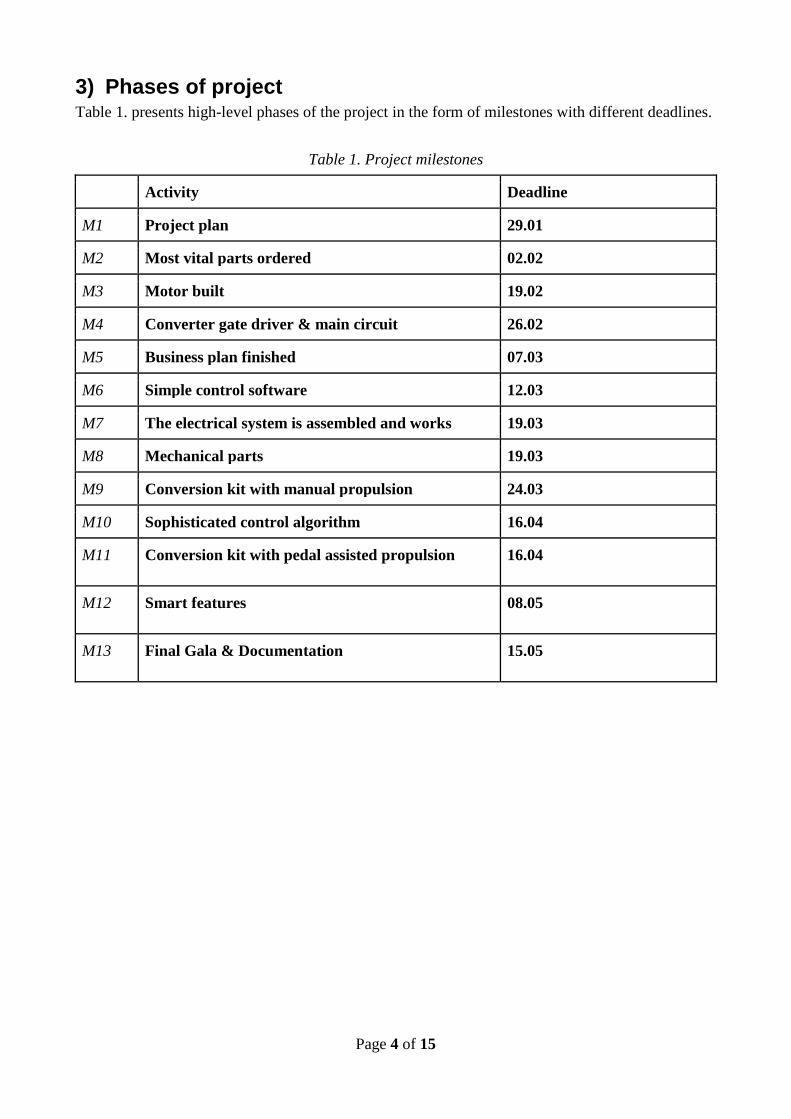
3) Phases of project Table 1. presents high-level phases of the project in the form of milestones with different deadlines.
Table 1. Project milestones
Activity Deadline
M1 Project plan 29.01
M2 Most vital parts ordered 02.02
M3 Motor built 19.02
M4 Converter gate driver & main circuit 26.02
M5 Business plan finished 07.03
M6 Simple control software 12.03
M7 The electrical system is assembled and works 19.03
M8 Mechanical parts 19.03
M9 Conversion kit with manual propulsion 24.03
M10 Sophisticated control algorithm 16.04
M11 Conversion kit with pedal assisted propulsion 16.04
M12 Smart features 08.05
M13 Final Gala & Documentation 15.05
Page 5 of 15
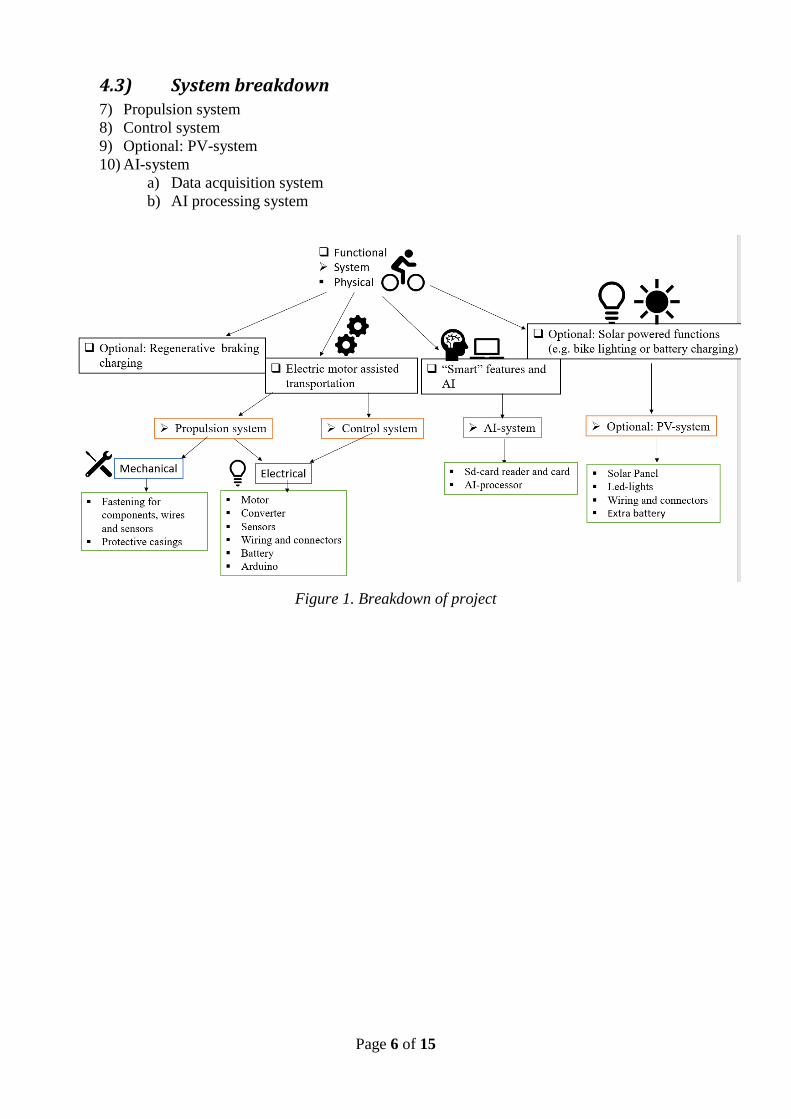
4) Work breakdown structure (WBS) To get a clear visualization of what must be implemented in the project this chapter aims to give an
overview of what is required to finish the project in the form of a physical, functional and system
breakdown. Figure 1 aims to illustrate the breakdown in an easily overviewable picture but excludes
some information mentioned in the text to retain clarity.
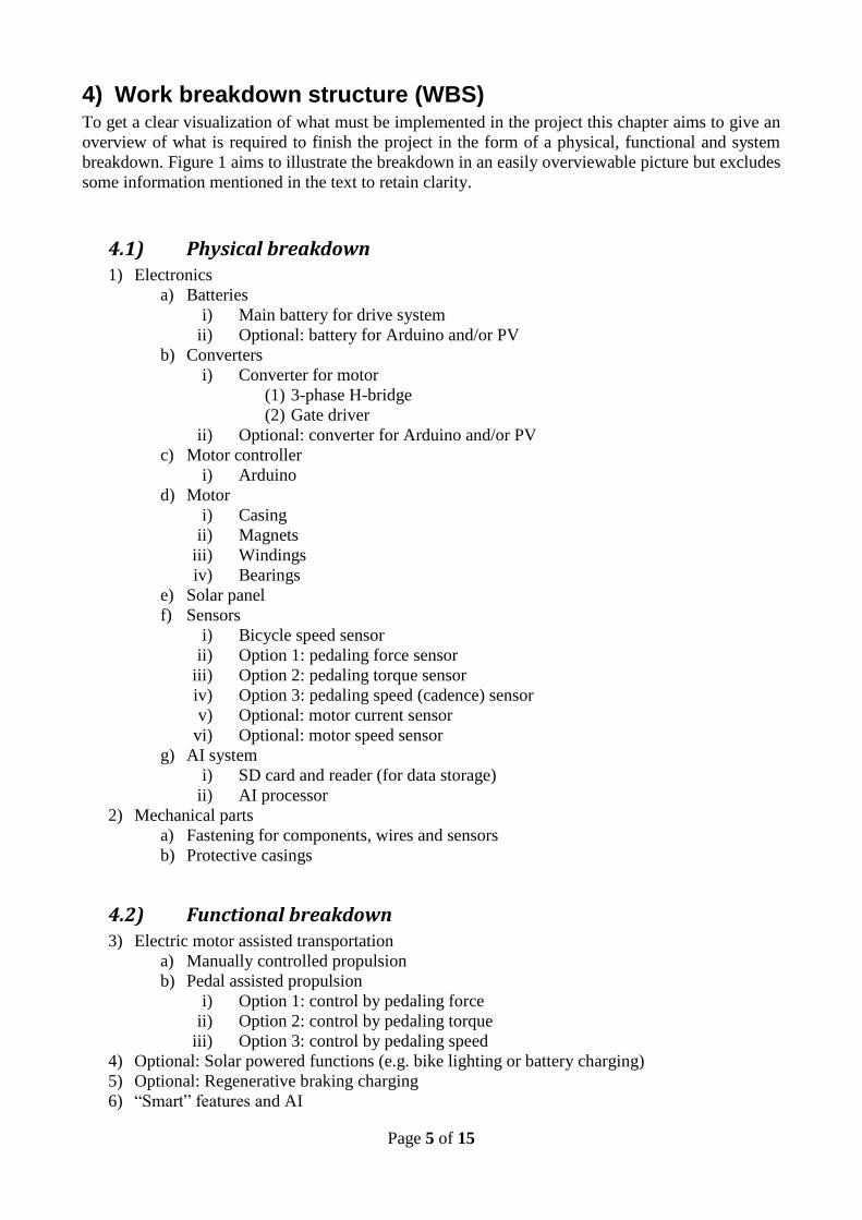
4.1) Physical breakdown 1) Electronics
a) Batteries
i) Main battery for drive system
ii) Optional: battery for Arduino and/or PV
b) Converters
i) Converter for motor
(1) 3-phase H-bridge
(2) Gate driver
ii) Optional: converter for Arduino and/or PV
c) Motor controller
i) Arduino
d) Motor
i) Casing
ii) Magnets
iii) Windings
iv) Bearings
e) Solar panel
f) Sensors
i) Bicycle speed sensor
ii) Option 1: pedaling force sensor
iii) Option 2: pedaling torque sensor
iv) Option 3: pedaling speed (cadence) sensor
v) Optional: motor current sensor
vi) Optional: motor speed sensor
g) AI system
i) SD card and reader (for data storage)
ii) AI processor
2) Mechanical parts
a) Fastening for components, wires and sensors
b) Protective casings
4.2) Functional breakdown 3) Electric motor assisted transportation
a) Manually controlled propulsion
b) Pedal assisted propulsion
i) Option 1: control by pedaling force
ii) Option 2: control by pedaling torque
iii) Option 3: control by pedaling speed
4) Optional: Solar powered functions (e.g. bike lighting or battery charging)
5) Optional: Regenerative braking charging
6) “Smart” features and AI
Page 6 of 15
4.3) System breakdown 7) Propulsion system
8) Control system
9) Optional: PV-system
10) AI-system
a) Data acquisition system
b) AI processing system
Figure 1. Breakdown of project
Page 7 of 15
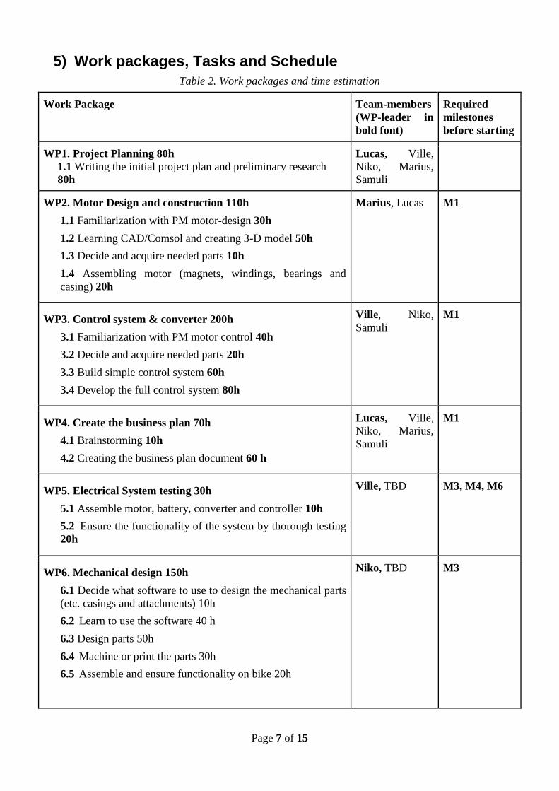
5) Work packages, Tasks and Schedule
Table 2. Work packages and time estimation
Work Package Team-members
(WP-leader in
bold font)
Required
milestones
before starting
WP1. Project Planning 80h
1.1 Writing the initial project plan and preliminary research
80h
Lucas, Ville,
Niko, Marius,
Samuli
WP2. Motor Design and construction 110h
1.1 Familiarization with PM motor-design 30h
1.2 Learning CAD/Comsol and creating 3-D model 50h
1.3 Decide and acquire needed parts 10h
1.4 Assembling motor (magnets, windings, bearings and
casing) 20h
Marius, Lucas M1
WP3. Control system & converter 200h
3.1 Familiarization with PM motor control 40h
3.2 Decide and acquire needed parts 20h
3.3 Build simple control system 60h
3.4 Develop the full control system 80h
Ville, Niko,
Samuli
M1
WP4. Create the business plan 70h
4.1 Brainstorming 10h
4.2 Creating the business plan document 60 h
Lucas, Ville,
Niko, Marius,
Samuli
M1
WP5. Electrical System testing 30h
5.1 Assemble motor, battery, converter and controller 10h
5.2 Ensure the functionality of the system by thorough testing
20h
Ville, TBD M3, M4, M6
WP6. Mechanical design 150h
6.1 Decide what software to use to design the mechanical parts
(etc. casings and attachments) 10h
6.2 Learn to use the software 40 h
6.3 Design parts 50h
6.4 Machine or print the parts 30h
6.5 Assemble and ensure functionality on bike 20h
Niko, TBD M3

Page 8 of 15
WP7. Smart features & AI 219h
7.1 Brainstorm AI ideas and decide what extra features to add
to the bike 20h
7.2 Decide on how to implement the AI in practicality 30h
7.3 Program the AI features 80h
7.4 Test the features and acquire data 49h
Samuli, TBD M7,M8
WP8. Preparation for final demonstration 60h
8.1 Writing final document 40h
8.2 Preparing the presentation 20h
Lucas, Ville,
Niko, Marius,
Samuli
M1-M12
Project Long tasks 200h
Weekly meetings x2 including agendas and memo-keeping
200 h
Lucas, Ville,
Niko, Marius,
Samuli
Total time used in the work packages: 1119 h
5.1) Detailed schedule A high-level Gantt chart consisting only of the individual work packages has been visualized in
figure 2. The reason for not going into task level is that the estimates are most likely too inexact to
be useful in this type of a chart. As can be seen the tasks are not sequential because we will do
work-packages in parallel, especially the control system and converter will require continuous work
and development throughout the project.
Figure 2. Gantt-chart of the work packages

Page 9 of 15
6) Work resources
6.1) Personal availability during the project
The project is a 10 credits course which means that each of us should spend about 270 hours each
on the course. Excluding 45 hours on lectures and common activities as defined during the project
planning lecture this comes out to 225 hours per person.
Table 3. Number of hours available for the project (excluding lectures and seminars) per week.
Lucas Samuli Niko Ville Marius Total INFO
Week 1 2 2 2 2 2 10
Week 2 8 8 8 6 8 38
Week 3 8 8 8 8 8 40
Week 4 12 12 12 12 6 54 exams
Week 5 12 12 16 12 6 58
Week 6 12 12 16 12 12 64
Week 7 12 12 20 12 20 76
Week 8 12 12 10 16 14 64 Business
Week 9 12 12 10 12 14 60 Business
Week
10 12 10 10 12 14 58 Business
Week
11 12 10 10 12 14 58
Week
12 12 10 10 12 14 58
Week
13 12 10 10 10 10 52
Week
14 0 4 2 4 4 14 Exams
Week
15 14 14 14 14 14 70
Week
16 14 14 14 14 14 70
Week
17 14 14 14 14 14 70
Week
18 14 14 14 14 14 70
Week
19 14 14 14 14 14 70
Week
20 14 14 14 0 5 47
Week
21 2 4 2 6 4 18 Exams
Total 224 222 230 218 225 1119

Page 10 of 15
6.2) Personal goals Lucas - My goal is to get some more experience of working in a project. Even though I have more
knowledge in the control aspect of the drive system I think it will be very interesting to build the
motor from scratch in WP2. Since I ended up as project manager my goal is to also try to learn
more about what a project manager does and lead this project as effectively as possible.
Samuli - The Electrical Power and Energy Engineering major has many courses related to power
electronics and electric drives. My first goal is to apply knowledge learned from these courses in
practical work. I want to be able to see what is takes to design and build actual devices compared to
simulations and theory. My second goal is to see what it takes to apply artificial intelligence in real
devices and see what kind of results the AI can achieve.
Ville - My goal is to learn project work and apply theory to practice with electric drives and
everything related to them. It’s good to have some practical work about designing and building a
real electric drive system along with the plethora of theoretical courses provided by the university.
Niko - My main goal is to advance my knowledge of power electronics, electric drive systems and
their control. This goal will be achieved by focusing especially on WP3 and WP5. My secondary
goal is to learn about different sensors and sensing in practice in WP7. Since I’m responsible for
mechanical design in WP6, I’m hoping to advance my workshop skills.
7) Cost plan and materials
The available budget for the project is a maximum of 1000€. When something has been ordered
something the cost of the item should be added to our internal budget tracking document in the
drive. All orders go through the instructor for approval before ordering/buying. Table 4. contains
rough estimates of the cost of components.
Table 4. Estimated budget
Item/Part Estimated Cost
Battery 250 €
Motor
Magnets 50€
Bearings, bolts, shaft 20€
70€
AI & Control
Arduino 40€
SD-card & reader 20€
60€
Converter
Gate driver & 3-ph H-bridge 60 €
Isolation circuit 10 €
70€
Other
sensors, fasteners, wires, roller...
150€
Total 600€

Page 11 of 15
8) Other resources Other resources available to the group that will help in completing this project includes:
• Free software for Aalto students such as Solid edge, Matlab and Comsol
• General access during open hours to “Sähköpaja” located in the TuAs-building.
• Access to the machine hall in Otakaari 5. The keys to the lab will be provided by the
instructor or if that is not possible a lab assistant will open the doors.
● Meeting rooms and computer classrooms on the Aalto campus.
9) Project management and responsibilities
This chapter aims to set up guidelines defining the responsibilities of the project participants.
Project Manager: The project manager is responsible for tracking that the team is meeting the
deadlines set by course. Furthermore, the manager creates a meeting agenda for each meeting and
assigns a memo keeper for each meeting. The project manager also keeps the group up to date on
the project status with a weekly update to the drive. Aside from these responsibilities the manager
participates in the project as everyone else.
Instructor: The instructor gives guidelines and help with the different technical aspects of the
project. This might for example include introduction to motor design tools and assistance with the
control system.
Work package leader: The work package leader is responsible for overseeing that the work is
done according to plan. This means meeting deadlines, reporting the status of the work to the
project manager. He is also working as a part of the team in the package.
Team member: Each team member is responsible for finding tasks to do, wither by asking the WP-
leader or the project manager or by own initiative. He also must report any complications or
problems that will lead to task failure to the work package leader or the project manager.
Other Advisors: Vesa Korhonen will be assisting the group with advice on the mechanical parts of
the project. This also extends to helping with for example purchasing the right components needed.
He will also help with the 3-d printing if it seems that the printing is complicated.

Page 12 of 15
10) Project Meetings
Meetings are held twice a week. Wednesdays at 12 pm at Otakaari 1 hub and at Fridays at 4 pm at
TUAS-3543. The instructor is present on the Friday meetings and therefore these meetings should
focus on issues that need his attention. Everyone is expected to arrive on time and meetings will
start no later than 5 minutes past the given time. In case of unavailability, the team member should
inform the group before the meeting.
The project manager creates an agenda before each meeting that will be available on the drive. The
project manager is also responsible for assigning a memo keeper each meeting. The memo should
be a summary of the most central parts discussed during the meeting and include who attended. The
meeting material is to be uploaded to the respective drive folder.
11) Communication plan Besides the weekly face to face meetings the following electronic communication methods will be
used.
Whatsapp: Whatsapp will be used for short messages that require fast attention, such as short
questions and updates.
Email: Email is used to exchange more detailed information that doesn’t require immediate action.
Google Drive: Drive is the cloud location that will be used for sharing all documents related to the
project.
Gitlab: Gitlab will be used as a method of source code sharing the code related to the AI-part of the
project if needed.
The instructor has access to both the Whatsapp group and the Google drive but the official method
for communicating with the instructor will be email.
12) Risks This project is a 10 cr course that takes about four months to complete and involves five team
members. From earlier experience in schoolwork one can safely say that the biggest risks in a
school project of this nature is that deadlines are not met and that someone in the team can’t
complete their task because of illness or some other reason. Since this project also consists of
building a physical product where electricity is involved this also introduces risk in the form of
material damage and injuries. Table 5 presents possible risks with different probabilities and
severity. The table also presents which preventive actions has to be taken and what action should be
taken minimize the consequences of the risk-events in the case that they happen

Page 13 of 15
Table 5. Risk analysis
Risk Probability Severity Action Prevention
Team member
absent
Medium Substantial Reassigning of
work and changing
the schedule/project
plan.
Everyone knows what is
expected of them and in case
of absence you are expected
to spend more time working
in later parts of the project.
Material
damage
Medium Minor Buy/make new part.
Make change in
schedule if part is
critical.
Everyone knows the tolerance
of the equipment they are
using and works in a calm and
calculated manner in the lab.
Injury or
Electrocution
Low Critical Seek medical care Ensure everyone knows how
to work safely in a lab.
Problems with
material
acquisition.
Medium High Try to work on
something that
doesn’t require the
parts in questions.
Order things in time and
account for shipment time in
the project schedule.
The estimated
times in
schedule are
wrong.
Extremely
High
Medium Re-evaluate the
time schedule.
Estimate the timetable as well
as possible
Some part of
the project is
too hard to
complete
Medium Critical Inform instructor
and ask for
help/tips. Modify
the project plan
according to
findings.
Reserve enough time for
learning and planning in each
work package.
Budget
doesn’t hold
Low Critical Consult instructor. Keep a clear overview of how
much has been spent and
remember that things
generally cost more than
estimated in the end.
Most of the risk presented should be preventable with clear communication and a good schedule. In
case something goes wrong the most important part is being flexible in modifying the plan in such a
way that the project can still be completed on time.

Page 14 of 15
13) Quality plan The aim of this project is to keep the quality as high as possible given the resources available. Each
individual team-member is responsible for the quality of his work and is to complete his work to the
best of his ability. The quality of the work in the individual work packages should be documented
regularly and discussed in the group meetings.
To keep the quality according to the customers, in this case the instructors, standards it is important
the the quality requirements of the end product and individual parts is clear when starting the work.
This will be ensured by weekly meetings with the instructor where such matters will be discussed.
Later on in the project when learning more about standardization and standards this knowledge
should also be implemented to ensure the quality.
If problems in quality occurs sufficient time must be allocated to solving the issue, whether this is
by further meetings and discussion or studying of the problem is to be decided based on the nature
of the problem at the weekly project meetings. The most important thing is that the problems are
clearly communicated in the group as soon as possible so that action can be taken to resolve the
issues.
14) Changing this plan The suggestion of changing the plan can be done by any team-member that sees room for
improvement or room for change. The suggestion should be clearly defined so that everyone
understands what the consequences of the change is. The decision to change the plan is taken at the
following group meeting and the decision requires a majority vote. The changes in the plan is
handled by revisions to the original plan.
Since the instructor has given the requirements of the project, a request of change in the project plan
can also come from the instructor. The changes in the plan is handled in the same way as in the case
of a team-member initiating the change.
15) Measures for successful project
Testing Software
Software can be unit tested if the expected output of the unit (function, class, etc.) is known.
For testing purposes, the code should be divided into small individual parts in the development
process. This makes testing easier and the code becomes more manageable.
In machine learning, the expected output of the software is usually very hard to estimate.
This means that some parts of the AI are also very hard to test. However, some approximate
expectations about the output can be assumed.
The main purpose of the software for Arduino is to output signals for the gate driver.
Thus, the final output can be tested by looking at the waveforms produced for example with
oscilloscope. In the development process the software can be tested by monitoring behavior of
individual software components. The secondary purpose is to acquire data for the AI and insert it to
the SD-card. This can be easily tested by looking at the content of the card after data acquisition.
Testing Hardware
The hardware can be tested by comparing it to the performance characteristics defined in chapter
Some of these characteristics are quite subjective such as how easy the installation is and how much
the electric motor really helps. But the more physical requirements such as battery life and ensuring
that the kit is legal are important factors to test and document. The principle of dividing the kit into

Page 15 of 15
individual parts should also be used, this means testing the motor and converter independently of
each-other if possible.
Evaluating project progress
One of the primary ways of evaluating the project progress and status is based on reaching the
milestones by their deadlines. However, meeting the deadline is not enough, the quality of the work
produced by the milestone also must be evaluated somehow. Therefore, after reaching a milestone
there should be documentation answering questions such as:
• What was made?
• How was it made?
• Performance/data
• How to use?
These questions will of course depend on the nature of the milestone. The central idea is that by
regularly documenting and evaluating what was made, the project process will be easy to follow,
and the final demonstration will be easier to complete.