project manual & contract documents for hope …
TRANSCRIPT

P A R E P R O J E C T N O . 0 8 1 4 6 . 3 1
PROJECT MANUAL &
CONTRACT DOCUMENTS
FOR
HOPE STREET PUMP STATION
ISSUED FOR CONSTRUCTION
Prepared for:
Bristol County Water Authority
450 Child Street
Warren, Rhode Island 02885
Prepared by:
Pare Corporation
8 Blackstone Valley Place
Lincoln, Rhode Island 02865
J U L Y 2 0 2 1

BRISTOL COUNTY WATER AUTHORITY
HOPE STREET PUMP STATION
Table of Contents
i
TABLE OF CONTENTS
BIDDING REQUIREMENTS, CONTRACT FORMS AND CONDITIONS OF THE
CONTRACT
00020 Invitation to Bid
00100 Instruction to Bidders
00200 Special Instructions to Bidders
00310 Bid Form
00400 Supplements to Bid Form
00500 Agreement
00510 Notice of Award
00550 Notice to Proceed
00610 Performance Bond
00615 Payment Bond
00700 General Conditions
00800 Supplementary Conditions
TECHNICAL SPECIFICATIONS
DIVISION 1 - GENERAL REQUIREMENTS
01010 General Description of the Work
01015 Contractor’s Use of the Premises
01019 Contract Considerations
01039 Coordination and Meetings
01040 Construction Schedules
01045 Cutting, Coring, and Patching
01060 Permits and Regulatory Requirements
01065 Project Safety and Health Specifications
01090 Reference Standards
01115 Emergency Response Plan
01150 Measurement and Payment (not included)
01170 Special Provisions
01300 Submittals
01400 Quality Control
01600 Material and Equipment
01650 Facility Start-up
01700 Contract Closeout
01800 Maintenance
DIVISION 2 - SITE WORK
02070 Selective Demolition
02200 Earthwork
02211 Rock Removal

BRISTOL COUNTY WATER AUTHORITY
HOPE STREET PUMP STATION
Table of Contents
ii
02273 Erosion Control
02513 Bituminous Concrete Pavement
02616 Ductile Iron Pipe and Fittings
02640 Valves, Tapping Sleeves, and Appurtenances
02704 Pipeline Pressure, Leakage and Disinfection
02831 Chainlink Fence
02900 Landscaping
DIVISION 3 - CONCRETE
03100 Concrete Formwork
03200 Concrete Reinforcement
03300 Cast-in-Place Concrete
DIVISION 4 - MASONRY
04200 Unit Masonry
DIVISION 11 - EQUIPMENT
11240 Pumps, Piping, and Related Equipment
11300 Chlorine Injection Pumps and Related Equipment
DIVISION 13 – SPECIAL CONSTRUCTION
13366 Instrumentation and Control System
13610 Instrumentation Systems Basic Requirements
13611 Magnetic Flow Meter
13612 Pressure Measurement
13613 Level Measurement
DIVISION 16 - ELECTRICAL
16050 Basic Electrical
16110 Raceway
16120 Wire and Cables
16130 Cabinets, Boxes, and Fittings
16140 Wiring Devices
16190 Supporting Devices
16195 Electrical Identification
16210 Standby Generator
16400 Service Entrance
16440 Disconnect Switches
16450 Grounding
16460 Transformers
16470 Panelboards
16480 Motor Control Centers
16481 Motor Starters
16490 Automatic Transfer Switch

BRISTOL COUNTY WATER AUTHORITY
HOPE STREET PUMP STATION
Table of Contents
iii
APPENDICES
Appendix A Hope Street Pump Station SCADA Operation
Appendix B Photos – Existing Drain, Overflow, and Inlet/Outlet Pipe for Hope Street Tank
NOTE: Bidders shall check the attached documents with the above list before submitting a bid.

BRISTOL COUNTY WATER AUTHORITY
HOPE STREET PUMP STATION
DIVISION 0
BIDDING REQUIREMENTS, CONTRACT FORMS AND CONDITIONS OF THE CONTRACT

BRISTOL COUNTY WATER AUTHORITY
HOPE STREET PUMP STATION
Invitation to Bid
00020 - 1
SECTION 00020 INVITATION TO BID
The Bristol County Water Authority (BCWA) is seeking sealed Bids for the Hope Street Pump Station Project. Work will include the construction of a new booster pump station and chlorine dosing facility, installation of a below ground valve vault, yard piping, and miscellaneous site improvements. Bids will be received by the BCWA until 10 AM on August 12, 2021, at their office at 450 Child Street, Warren RI 02885, at which time the bids will be opened and publically read aloud. Bids must be enclosed in sealed envelopes and labeled as required in Part 6.2 A. of the Instructions to Bidders. All Bids must be submitted on the form in the Contract Documents and clearly marked:
Hope Street Pump Station Prospective Bidders are asked to attend a mandatory Pre-Bid Conference on July 22, 2021, at 10 AM, to be held at the BCWA office at 450 Child Street, Warren, RI. Individuals requesting interpreter services for the hearing impaired or require handicap accessible facilities should call the BCWA at 401-245-2022 a minimum of seventy-two (72) hours in advance of the Pre-Bid Conference. Contract documents may be obtained from BCWA by emailing Susan Rabideau, P.E. at [email protected], downloading from the BCWA website (www.bcwari.com/bids), or picked up at the Administrative Office at 450 Child Street, Warren, RI between the hours of 8:30 am and 3:30 pm, weekdays. A refundable payment of $50.00 in cash or check payable to the Bristol County Water Authority will be required for each hard copy set of the Contract Documents. Bidders requesting Contract Documents by mail shall add an additional non-refundable check payable to the Bristol County Water Authority in the amount of $15.00 per set to cover costs of handling and mailing. All work under this contract is subject to the prevailing wage rate of the State of Rhode Island. Certified payrolls will be required to be submitted for all work under this contract. Bid prices must reflect adherence to the provisions of State Labor Laws concerning payment of prevailing wages (see RI General Laws Sec 37-13-1 et seq. as amended). The rates of pay set forth in these provisions are the minimums to be paid during the life of the contract. Bidders shall inform themselves as to the local labor conditions such as the length of workday and workweek, overtime compensation, health and welfare contributions, labor supply, and prospective changes or adjustment of rates. Bid Security in the form identified within the Instruction to Bidders, and in the amount of five (5) percent of the total Bid amount, must accompany each bid. The successful Bidder must furnish a Performance and a Labor and Material Payment Bond, in the specific formats as attached herein, both for the full value of the Bid Price, along with all required insurance certificates, within ten (10) calendar days after the award date in order to execute a Contract. No Bidder may withdraw his Bid within sixty (60) days following the closing time for receipt of Bids.

BRISTOL COUNTY WATER AUTHORITY
HOPE STREET PUMP STATION
Invitation to Bid
00020 - 2
Time of completion is set at 270 days following the Notice to Proceed to complete all work. The Notice to Proceed is anticipated to be issued by DATE. Liquidated damages will be in the amount of $1500.00 for each calendar day of delay from the date established for substantial completion.
The BCWA reserves the right to reject any and all Bids or parts thereof, to waive any irregularity in the Bids received, and to accept the Bid or parts thereof deemed to be most favorable to the best interest of the BCWA.
END OF SECTION

BRISTOL COUNTY WATER AUTHORITY
HOPE STREET PUMP STATION
Instruction to Bidders
00100 - 1
SECTION 00100 INSTRUCTIONS TO BIDDERS PART 1 SUMMARY
1.1 DOCUMENT INCLUDES
A. Invitation
1. Receipt and Opening of Proposals 2. Intent 3. Work Identified in the Contract Documents 4. Contract Period and Term of Agreement 5. Telegraphic Modification 6. Obligations of the Bidder 7. Prices
B. Bid Documents and Contract Documents
1. Definitions 2. Contract Documents Identification 3. Availability 4. Examination 5. Addenda and Interpretations 6. Product/System Substitutions 7. Delivery
C. Site Assessment
1. Site Examination 2. Pre Bid Conference
D. Qualifications
1. Qualifications of the Bidder 2. Subcontractors/Suppliers/Others
E. Bid Submission
1. Preparation of Bid 2. Submission of Bids
F. Bid Enclosures/Requirements
1. Bid Security 2. Agreement to Bond 3. Performance Bond and Labor and Material Payment Bond 4. Insurance 5. Bid Form Requirements 6. Bid Form Signature

BRISTOL COUNTY WATER AUTHORITY
HOPE STREET PUMP STATION
Instruction to Bidders
00100 - 2
7. Prevailing Wage Rates 8. Tax Exemption 9. Labor Regulations 10. Additional Bid Information
G. Offer Acceptance/Rejection
1. Duration of Offer 2. Withdraw of Bids 3. Acceptance of Offer
H. Laws, Ordinances and Codes
I. Time of Completion and Liquidated Damages
J. Permits
PART 2 INVITATION 2.1 RECEIPT AND OPENING OF PROPOSALS
A. Sealed bids/proposals will be accepted and time stamped upon receipt at the BCWA office, 450 Child Street, Warren, RI 02885; until the time, indicated on the attached Invitation to Bid, for the commodities, equipment or services listed in the specifications. Bid/Proposals will be publicly read at the time specified in the advertisement.
B. Proposals submitted for a specified item must not be combined under the same cover with any
other Bid item.
C. Any Bid received after the time and date specified shall not be considered, by messenger or by mail, even if it is determined by the BCWA or the Engineer that such non-arrival before the time set for opening was due solely to delay in the mails for which the Bidder is not responsible. Conditional or qualified Bids will not be accepted.
D. Submit Document 00400 - Supplements to Bid Forms with Bid Submission.
2.2 INTENT
A. The intent of this Bid request is to solicit bids for the labor and materials necessary to install a new pump station and chorine facility, one (1) new above-grade hot box structure, demolition of the existing Hope Street pump station building, and miscellaneous site improvements as part of the Hope Street Pump Station project.
2.3 WORK IDENTIFIED IN THE CONTRACT DOCUMENTS
A. Scope: The scope of this project includes, but is not limited to, the installation of a new water booster pump station and chorine facility, one (1) new below ground valve vault, yard piping, and miscellaneous site improvements as shown on the design drawings.
BRISTOL COUNTY WATER AUTHORITY
HOPE STREET PUMP STATION
Instruction to Bidders
00100 - 3
B. The Owner hereby reserves the right, at any time, or from time to time, to order additions, deletions, or revisions in the work to be authorized through a written amendment (change order), which shall be subject to the provisions in General Conditions - Article 10.
2.4 CONTRACT PERIOD AND TERM OF AGREEMENT
A. Time of completion is set at 270 days following the Notice to Proceed to complete all work. 2.5 TELEGRAPHIC MODIFICATION
A. Telephonic, telegraphic or oral Bids, amendments or withdrawals will not be accepted. 2.6 OBLIGATIONS OF THE BIDDER
A. At the time of opening of Bids, each Bidder will be presumed to have inspected the Specifications and Contract Documents (including all Addenda), which have been sent to the address given by such Bidder. The failure or omission of any Bidder to receive or examine any form, instrument, or document or to inspect any item specified as a Trade-in shall in no way relieve any Bidder from any obligation in respect to his Bid.
B. Any exceptions or deviations from the provisions contained in this Specification must be
explained in detail and attached to the proposal. If such deviations do not depart from the intent of this notice and are in the best interest of the BCWA, the proposal will receive careful consideration.
2.7 PRICES
A. Bidders shall state the proposed price in the manner as designed in the Bid Proposal Form. In the event that there is a discrepancy between unit prices and the extended totals, the unit price shall govern. In the event that there is a discrepancy between the price written in words and written in figures, the prices written in words shall govern.
B. Bidders agree that the price in this Bid shall be irrevocable for 60 days, or until the Bid is
awarded by the BCWA. After award by the BCWA, said prices shall then remain firm for the duration of the Contract.
PART 3 BID DOCUMENTS AND CONTRACT DOCUMENTS
3.1 DEFINITIONS
A. Bid Documents: Contract Documents supplemented with Invitation to Bid, Instructions to Bidders, Bid Form, Supplements to Bid Forms, Appendices and Bid Securities, identified herein.
B. Contract Documents: Defined in EJCDC 1910-8 Article 1, including issued Addenda.
C. Bid, Offer, or Bidding: Act of submitting an offer under seal.
D. Bid Price: Monetary sum identified by the Bidder in the Bid Form.
BRISTOL COUNTY WATER AUTHORITY
HOPE STREET PUMP STATION
Instruction to Bidders
00100 - 4
E. Owner: Bristol County Water Authority
F. Engineer: Pare Corporation 3.2 CONTRACT DOCUMENTS IDENTIFICATION
A. The Contract Documents are identified by the project title, “Hope Street Pump Station Project”, as prepared by the Engineer, Pare Corporation located at 8 Blackstone Valley Place, Lincoln, RI and identified in the Table of Contents, Project Manual, and Specifications.
3.3 AVAILABILITY
A. Additional copies of the Bid Documents may be obtained at BCWA office, 450 Child Street, Warren, RI 02885 between the hours of 8:30 a.m. and 3:30 p.m., Monday through Friday. Bid documents are also available by emailing Susan Rabideau, P.E. ([email protected]).
B. Bid Documents are made available only for the purpose of obtaining offers for this project.
Their use does not grant a license for other purposes. 3.4 EXAMINATION
A. Bid Documents may be viewed at the office of the Engineer.
B. Upon receipt of Bid Documents verify that documents are complete. Notify Engineer should the documents be incomplete.
C. Immediately notify the Engineer upon finding discrepancies or omissions in the Bid
Documents. 3.5 ADDENDA AND INTERPRETATIONS
A. No interpretation on the meaning of the Plans, Specifications or other Contract Documents will be made to any Bidder orally. Every request for such interpretations should be in writing, addressed to BCWA, or emailed to Susan Rabideau, P.E. ([email protected]). To be given consideration the request must be received at least seven (7) days prior to the date fixed for the opening of the bids. Fax transmissions will be accepted with written follow-up by Bidder.
B. Any and all interpretations, and supplemental instructions, which, if issued, will be mailed by
regular mail, emailed or faxed to all perspective Bidders (at the respective address furnished by the Bidder for such purpose), not later than 48 hours prior to the date fixed for the opening of the bids (unless such addenda postpones the opening of bids). Failure of Bidder to receive any such addendum or interpretations shall not relieve any Bidder from obligation under this bid as submitted. All addenda so issued shall become part of the Contract Documents.
BRISTOL COUNTY WATER AUTHORITY
HOPE STREET PUMP STATION
Instruction to Bidders
00100 - 5
3.6 PRODUCT/SYSTEM SUBSTITUTIONS
A. Where the Bid Documents stipulate a particular Product, substitutions will be considered by the Engineer up to 10 days before receipt of Bids.
B. The submission shall provide sufficient information to determine acceptability of such
products.
C. When a request to substitute a Product is made, the Engineer may approve the substitution and will issue an Addendum to known Bidders.
D. In submission of substitutions to products specified, Bidders shall include in their Bid, any changes required in the Work and changes to Contract Time and Contract Price to accommodate such substitutions. A later claim by the Bidder for an addition to the Contract Time or Contract Price because of changes in Work necessitated by use of substitutions shall not be considered.
3.7 DELIVERY
A. All Purchases related to this bid are to be delivered FOB to the BCWA, delivery to be supplied with the Purchase Order. No extra charges for delivery, handling or other services will be honored. Only inside delivery and set-up, where required, will be accepted. TAILGATE DELIVERIES WILL BE REFUSED. The vendor must notify the BCWA 24 hours prior to delivery. All claims for damage in transit shall be the responsibility of the successful Bidder. The BCWA will not make payment on damaged goods, they must be replaced or adjustments made at the option of the BCWA. The BCWA is only represented by the Executive Director of the BCWA or their designated representative in these matters and shall be the only entity to negotiate any settlements. Deliveries must be made during normal working hours.
B. Bid price is to include the cost of uncrating and setting in place where noted.
C. Bid price is to include installation where noted.
PART 4 SITE ASSESSMENT
4.1 SITE EXAMINATION
A. All general contractors (or Bidders), and major subcontractors are required to examine the project site before submitting a Bid.
4.2 PRE BID CONFERENCE
A. A mandatory Pre Bid Conference has been scheduled for 10:00 AM on DATE at the BCWA offices, 450 Child Street, Warren, RI.
B. All general contract and subcontract Bidders are invited.
C. Representatives of the Owner and Engineer will be in attendance.

BRISTOL COUNTY WATER AUTHORITY
HOPE STREET PUMP STATION
Instruction to Bidders
00100 - 6
D. Information relevant to the Bid Documents will be recorded in an Addendum, if applicable, and issued to all known Bid Document recipients.
PART 5 QUALIFICATIONS
5.1 QUALIFICATIONS OF THE BIDDER
A. The BCWA may make such investigations as deemed necessary to determine the ability of the Bidder to perform the Work, and the Bidder shall furnish to the BCWA all such information and data for this purpose as the BCWA may request.
B. The BCWA reserves the right to reject any Bid if the evidence submitted by, or investigation
of, such Bidder fails to satisfy the Owner or the Engineer that such Bidder is properly qualified to carry out the obligations of the Contract and to complete the Work contemplated therein.
5.2 SUBCONTRACTORS/SUPPLIERS/OTHERS
A. The Owner or the Engineer reserves the right to reject a proposed Subcontractor for reasonable cause.
B. Refer to Article 6.06 of EJCDC General Conditions.
PART 6 BID SUBMISSION
6.1 PREPARATION OF BID
A. Each Bid must be submitted on the prescribed form and submitted in duplicate. All blank spaces for Bid prices must be filled in ink or typewritten, both in words and figures. All Bids must be prepared in conformity with and shall be based on and submitted subject to all requirements of the Specifications and Drawings, together with all Addenda thereto.
B. Erasures or other changes must be explained or noted over the signature of the Bidder.
C. Each Bid must be submitted in sealed envelopes, clearly labeled, so as to guard against
opening prior to the time set therefore.
D. Supplemental information, drawings, warranties, literature and material to be provided with the Bid shall be on the Bidder’s own form.
6.2 SUBMISSION OF BIDS
A. Envelopes containing Bids must be sealed and marked with the name and address of the Bidder with the label “Bid Submission: Hope Street Pump Station” That envelope is to be placed inside another sealed enveloped which has been addressed as follows: Bristol County Water Authority 450 Child Street Warren, RI 028885 Attention: Bid Proposal

BRISTOL COUNTY WATER AUTHORITY
HOPE STREET PUMP STATION
Instruction to Bidders
00100 - 7
B. Any Bidder may withdraw his Bid by written request at any time prior to the advertised time for opening. Telephone bids, faxed bids, amendments or withdrawals will not be accepted.
C. Unless otherwise specified, no Bid may be withdrawn for a period of sixty days (60) from the
time of Bid opening.
D. Negligence on the part of the Bidder in preparing the bid confers no rights for the withdrawal of the Bid after it has been opened.
E. Proposals received prior to the time of opening will be securely kept, unopened. No
responsibility will be attached to an officer or person for the premature opening of a proposal not properly addressed and identified.
F. Any deviation from the Specifications MUST BE NOTED IN WRITING AND ATTACHED AS PART OF THE BID PROPOSAL. The Bidder shall indicate how the Bid will deviate from Specifications.
PART 7 BID ENCLOSURES/REQUIREMENTS
7.1 BID SECURITY
A. Each Bid proposal must be accompanied by Bid security (security deposit) in the form of a Bid Bond, payable to the BCWA, in the amount of 5% of the total amount Bid. Bid security of the successful Bidder will be retained by the BCWA until Bid requirements are met or forfeited to the BCWA upon Bidder's failure to perform contract obligations.
B. Any successful Bidder withdrawing his Bid subsequent to Bid opening shall forfeit his Bid
deposit.
C. Include the cost of Bid Security in the Bid Price.
D. Bid Bonds shall remain valid and in force for the entire Bid eligibility period (i.e., 60 days from Bid opening).
7.2 AGREEMENT TO BOND
A. Submit with the Bid all surety requirements, provisions, and enclosures. 7.3 PERFORMANCE BOND AND LABOR AND MATERIAL PAYMENT BOND
A. The successful Bidder will be required to furnish the BCWA with a Performance Bond and a Labor and Material Payment Bond, each in the amount of 100% of the contract price, as security for faithful performance of the Contract and executed by a surety company licensed to do business in the State of Rhode Island and approved by the BCWA.
B. The failure of the successful Bidder to supply the required Bonds within a time specified or
within such extended period as the BCWA may grant based upon reasons determined sufficient by the BCWA, shall constitute a default, and the BCWA may either award the contract to the next lowest Bidder or re-advertise for Bids.

BRISTOL COUNTY WATER AUTHORITY
HOPE STREET PUMP STATION
Instruction to Bidders
00100 - 8
7.4 INSURANCE
A. The Contractor shall assume responsibility and liability for all injuries to persons or damages to property, directly or indirectly due to, or arising out of, his operations under the contract and shall be responsible for the proper care and protection of all work performed until completion and final acceptance by the BCWA.
B. The Contractor shall also indemnify and save harmless the BCWA against any and all claims
of whatever kind and nature due to, or arising out of, his breach or failure to perform any of the terms, conditions, or covenants of the contract resulting from acceptance of his Bid.
C. The Contractor shall furnish certificates of insurance from companies acceptable to the
BCWA. All Insurance Companies listed on certificate must be licensed to do business in the State of Rhode Island. The Contractor shall provide a certificate of insurance as specified on the Bid proposal form. Contracts of insurance (covering all operations under this contract) shall be kept in force until the Contractor's work is accepted by the BCWA.
D. The Contractor shall secure, pay for and maintain insurance as necessary to protect
himself/herself against loss of owned or rented capital equipment and tools, with provision for waiver of subrogation against the Owner.
E. The Contractor shall require a similar insurance in the above amounts to be taken out and
maintained by each sub-contractor. The Contractor shall be fully responsible for the acts and omissions of its sub-contractors and of persons employed either directly or indirectly by them, as it is for the acts and omissions of persons directly employed by the Contractor. Nothing contained in the contract shall create any contractual relation between any sub-contractor and the BCWA.
7.5 BID FORM REQUIREMENTS
A. Complete all requested information in the Bid Form and Attachments. 7.6 BID FORM SIGNATURE
A. The Bid Form shall be signed by the Bidder, as follows:
1. Sole Proprietorship: Signature of sole proprietor in the presence of a witness who will also sign. Insert the words "Sole Proprietor" under the signature. Affix seal.
2. Partnership: Signature of all partners in the presence of a witness who will also sign. Insert the word "Partner" under each signature. Affix seal to each signature.
3. Corporation: Signature of a duly authorized signing officer(s) in their normal signatures. Insert the officer's capacity in which the signing officer acts, under each signature. Affix the corporate seal. If the Bid is signed by officials other than the President and Secretary of the company, or the President/Secretary/Treasurer of the company, a copy of the by-law resolution of the Board of Directors authorizing them to do so, must also be submitted with the Bid Form in the Bid envelope.
4. Joint Venture: Each party of the joint venture shall execute the Bid Form under their respective seals in a manner appropriate to such party as described above, similar to the requirements of a Partnership.

BRISTOL COUNTY WATER AUTHORITY
HOPE STREET PUMP STATION
Instruction to Bidders
00100 - 9
7.7 PREVAILING WAGE RATES
A. Bid prices must reflect adherence to the provisions of State Labor Laws concerning payment of prevailing wages (see RI General Laws Sec. 37-13-1 et seq. as amended). The rates of pay set forth in these provisions are the minimums to be paid during the life of the contract. Bidders shall inform themselves as to the local labor conditions such as the length of workday and workweek, overtime compensation, health and welfare contributions, labor supply and prospective changes or adjustment of rates.
7.8 TAX EXEMPTION
A. Rhode Island Sales and Use Tax: Materials and equipment purchased for installation under this Contract are exempt from the Rhode Island Sales Tax. The exemption from the Sales Tax shall be taken into account by the CONTRACTOR during Bidding.
B. Rhode Island Sales Tax: The BCWA is exempt from the payment of Rhode Island Sales Tax under the 1956 General Laws of the State of Rhode Island, 44-18-30 Paragraph 1, as amended.
C. Federal Excise Taxes: The BCWA is exempt from the payment of any excise or federal
transportation taxes. The price Bid must be exclusive of taxes and will be so construed. 7.9 LABOR REGULATIONS
A. The following paragraphs regarding labor regulations shall be included and become part of these Specifications:
1. Non-resident Contractors are subject to Section 44-1-6 of the Rhode Island General
Laws, as amended. (OUT OF STATE CONTRACTORS). 2. The successful Bidder will be required to comply with the Contract Work Hours and
Safety Standards Act (40 USC 327-330) as supplemented by Department of Labor Regulations (29 CFR, Part 5).
3. The successful Bidder will be required to comply with the Safety and Health Regulations (29 CFR, Part 1926 and all subsequent amendments) as promulgated by the Department of Labor.
4. The successful Bidder will be required to comply with Title VI of the Civil Rights Act of 1964 (P.L. 88-352).
B. Bidders must, if required, submit a compliance report concerning their employment practices
and policies in order to maintain their eligibility to receive award of the Contract. 7.10 ADDITIONAL BID INFORMATION
A. The Owner requires that the Bidders complete the Supplements to Bid Forms and Appendices identified in Section 00400 and attach with the submission of Bids.
1. Appendix A - Subcontractors 2. Appendix B - Qualifications of Bidder

BRISTOL COUNTY WATER AUTHORITY
HOPE STREET PUMP STATION
Instruction to Bidders
00100 - 10
Failure to comply with these stipulations will be grounds for disallowing Bids at the Owner's or Engineer’s discretion.
PART 8 OFFER ACCEPTANCE/REJECTION
8.1 DURATION OF OFFER
A. Bids shall remain open to acceptance and shall be irrevocable for a period of sixty (60) days after the Bid closing date.
8.2 WITHDRAWAL OF BIDS
A. Bids may be withdrawn personally or by written request at anytime prior to the time specified for the opening. Bids may be modified in the same manner. Negligence on the part of the Bidder in preparing the Bid confers no right of withdrawal or modification of his Bid after such Bid has been opened.
8.3 ACCEPTANCE OF OFFER
A. The Owner reserves the right to accept or reject any or all offers.
B. After acceptance by the Owner, the BCWA will issue to the successful Bidder, a written Bid Acceptance, letter of Contract Award, and Notice to Proceed.
PART 9 LAWS, ORDINANCES, AND CODES
A. All applicable Federal and State Laws, Ordinances and Codes of the Town of Bristol and
Regulations of all authorities having jurisdiction over this Project shall apply to this contract the same as though written herein in full.
B. The BCWA will not award the Contract to any contractor who is, at the time, ineligible under
the provisions of any applicable regulations issued by the Secretary of Labor, United States Department of Labor, or is not qualified under applicable Ordinances of the Towns of Bristol, Warren, or Barrington, or the laws of the State of Rhode Island. If the successful Bidder is a corporation NOT authorized to do business in the State of Rhode Island, it shall qualify to do business in the State of Rhode Island, immediately after the award of the contract.
C. The successful bidder must provide proof of liability and worker’s compensation insurance coverage in the aggregate minimum amount as specified herein. Such proof of insurance must specify the BCWA as additionally insured and as certificate holder.
PART 10 TIME OF COMPLETION AND LIQUIDATED DAMAGES
A. The Bidder must agree to commence Work on or before the date specified in the written
Notice to Proceed of the Owner, and to substantially complete the Project within 270 consecutive calendar days. The Bidder must agree also to pay as liquidated damages, the sum of $1,500 for each consecutive calendar day thereafter as hereinafter provided in the Contract and General Conditions.

BRISTOL COUNTY WATER AUTHORITY
HOPE STREET PUMP STATION
Instruction to Bidders
00100 - 11
PART 11 PERMITS
A. The Contractor shall obtain and pay for all other Permits as required by the Town of Bristol
and the State (i.e., traffic control, general building, mechanical, curb cut, electrical, telephone, etc.).
END OF SECTION
BRISTOL COUNTY WATER AUTHORITY
HOPE STREET PUMP STATION
Special Instruction to Bidders
00200 - 1
SECTION 00200 SPECIAL INSTRUCTIONS TO BIDDERS
ARTICLES
1. AWARD & CONTRACT
2. CONDITION OF WORK
3. INFORMATION SUPPLIED TO BIDDERS
4. METHOD OF AWARD
5. EXECUTION OF THE AGREEMENT
6. NOTICE TO PROCEED
7. POWER OF ATTORNEY
8. UNCERTAINTY OF QUANTITIES
9. ITEMS NOT LISTED IN THE BID
10. BALANCED BIDDING
11. NOTICE OF SPECIAL CONDITIONS
12. JOB CONDITIONS
13. PRECONSTRUCTION CONFERENCE

BRISTOL COUNTY WATER AUTHORITY
HOPE STREET PUMP STATION
Special Instruction to Bidders
00200 - 2
SPECIAL INSTRUCTIONS TO BIDDERS
ARTICLE 1: AWARD AND CONTRACT
Unless otherwise specified, the Bristol County Water Authority (BCWA, also referred to as OWNER)
reserves the right to make award by item or items, or by total, as may be in the best interest of the BCWA.
A written award (or acceptance of Bid) mailed (or otherwise furnished) to the successful Bidder followed
by a Purchase Order shall, unless otherwise specified, be deemed to result in a binding Contract without
further action by either party.
ARTICLE 2: CONDITION OF WORK
Insofar as possible, the CONTRACTOR, in carrying out his Work, must employ such methods or means
as will not cause any interruption of or interference with traffic, with the use of existing facilities and
utilities, with the use of municipally or State or privately owned lands, or with the Work being performed
by others. The CONTRACTOR must satisfy himself by his own investigation and research as to the
nature and location of the Work, the general and local conditions, including, but not restricted to those
bearing upon the transportation, disposal, handling and storage of materials, water, electric power, roads,
means of access, the construction and making of connections of the Work to existing facilities and
utilities, or other similar conditions at the site, the character of equipment and facilities needed
preliminary to and during the prosecution of the Work, requirements of owners and controlling authorities
having jurisdiction over the various lands, existing structures, facilities and utilities, and all other
conditions affecting the Work to be done and labor and materials needed.
ARTICLE 3: INFORMATION SUPPLIED TO BIDDERS
The OWNER shall provide to bidders prior to bidding all information, which is pertinent to, and
delineates and describes, the land owned and rights-of-way acquired or to be acquired.
The Contract Documents contain the provisions required for the construction of the Project. Information
obtained from any officer, agent, or employee of the OWNER or any other person shall not affect the
risks or obligations assumed by the CONTRACTOR or relieve him from fulfilling any of the conditions
of the Contract.
ARTICLE 4: METHOD OF AWARD
If, at the time this Contract is to be awarded, the lowest base bid submitted by a responsible bidder does
not exceed the amount of funds then estimated by the OWNER as available to finance the Contract, the
Contract may be awarded on the base bid. If such bid exceeds such amount, the OWNER expressly
reserves the right to increase or decrease any class, item, or part of the Work, and this reservation includes
the omission of any such item, items, class or part of the Work as may be decided by the OWNER at the
unit prices submitted by the bidder to bring the Contract within available funds; or the OWNER may
reject all bids.
BRISTOL COUNTY WATER AUTHORITY
HOPE STREET PUMP STATION
Special Instruction to Bidders
00200 - 3
ARTICLE 5: EXECUTION OF THE AGREEMENT
A Contract in the form set forth hereinafter will be required to be executed by the successful bidder and
the OWNER. The attention of all bidders, therefore, is called to the form of the Agreement and the
provisions thereof. The party to whom the Contract is awarded will be required to obtain the performance
bond and payment bond within ten (10) calendar days from the date when the Notice of Award is
delivered to the bidder. The Notice of Award shall be accompanied by the necessary Agreement and
bond forms. The CONTRACTOR shall furnish a Performance Bond and a Payment Labor and Material
Bond, each in the amount of 100 percent of the Contract Price, with a corporate surety approved by the
OWNER, as security for faithful performance of Contract.
The OWNER, within thirty (30) days of receipt of an acceptable performance bond, payment bond and
Agreement signed by the party to whom the Agreement was awarded, shall sign the Agreement and return
to such party an executed duplicate of the Agreement. Should the OWNER not execute the Agreement
within such period, the bidder may, by written notice, withdraw his signed Agreement. Such notice by
withdrawal shall be effective upon receipt of the notice by the OWNER.
ARTICLE 6: NOTICE TO PROCEED
The Notice to Proceed is anticipated to be issued within 30 days of Notice of Award by the OWNER.
Should there be reasons why the Notice to Proceed cannot be issued within such period, the time may be
extended by mutual agreement between the OWNER and CONTRACTOR. If the Notice to Proceed has
not been issued within the period mutually agreed upon, the CONTRACTOR might terminate the
agreement without further liability on the part of either party.
ARTICLE 7: POWER OF ATTORNEY
Attorney-in-fact who sign bid bonds or Contract bonds must file with each bond a certified and
effectively dated copy of their power of attorney.
ARTICLE 8: UNCERTAINTY OF QUANTITIES
The quantities listed in the Bid (proposal) are approximate and are given only for use in comparing Bids
and to indicate approximately the total amount of the Contract; and the OWNER does not expressly or by
implication represent that the actual amounts of Work will even approximately correspond therewith, but
does call particular attention to the uncertainty of the quantities of the Work involved, which cannot be
predicted in advance. The Work under certain items may be materially greater or less than that given in
the Bid, as may be necessary in the judgment of the OWNER to complete the Work contemplated in the
Contract.
Under the Contract, the OWNER reserves the right to increase or decrease the approximate quantities for,
or to omit entirely, any of the items as listed in the Bid.
Only such quantities of the respective items of Work actually performed and accepted will be paid for.
An increase or decrease in the quantity for any item shall not be regarded as grounds for an increase or
decrease in the bid prices.

BRISTOL COUNTY WATER AUTHORITY
HOPE STREET PUMP STATION
Special Instruction to Bidders
00200 - 4
ARTICLE 9: ITEMS NOT LISTED IN THE BID
Appurtenant items of Work shown on the Drawings or specified or required to complete the Work, but
not listed separately under the list of items in the Bid, shall be included in the cost of payment under the
various applicable Bid Items. It shall be the responsibility of the CONTRACTOR to verify any missing
or incomplete items.
ARTICLE 10: BALANCED BIDDING
Minus bidding on any item or items of the Specification is prohibited. Bids should be made on each
separate item of Work shown in the Bid (proposal) with reasonable relation to the probable cost of doing
the Work included in such item, and the right is reserved to reject wholly any bid in case any item or
items thereof are obviously unbalanced or appear to the OWNER to be so unbalanced as to affect or to be
liable to affect adversely any interests of the OWNER. The attention of the Bidder is called to the fact
that unbalancing of bids may adversely affect the CONTRACTOR, if certain portions of the Work are
increased or decreased as provided in the Contract Documents.
ARTICLE 11: NOTICE OF SPECIAL CONDITIONS
Attention is particularly called to those parts of the Contract Documents and Specifications, which deal
with the following:
a. inspection and testing of materials,
b. insurance requirements,
c. wage rates,
d. interpretation of Drawings and Specifications,
e. the use of explosives and protection.
ARTICLE 12: JOB CONDITIONS
The Bidder is advised that free vehicular and pedestrian access must be maintained to the major streets.
The scheduling of work on or adjacent to the State roadway will be dictated by RIDOT Permit
requirements.
ARTICLE 13: PRECONSTRUCTION CONFERENCE
The CONTRACTOR shall be prepared to attend a pre-construction conference scheduled by the OWNER
after award of the Contract, but prior to the actual commencement of Work at the site. The main item of
discussion will be the CONTRACTOR's construction schedule, proposed Superintendent, Professional
Engineer or Land Surveyor, etc.
END OF SECTION

BRISTOL COUNTY WATER AUTHORITY
HOPE STREET PUMP STATION
Bid Form
00310 - 1
SECTION 00310 BID FORM
To: Bristol County Water Authority
450 Child Street
Warren, Rhode Island 02885
Project: Hope Street Pump Station
July 2021
Pare Project No. 08146.31
Date:
Submitted by:
(Full name)
(Full address)
1.00 OFFER
Having examined the Place of the Work and all matters referred to in the Instructions to Bidders and
Special Instruction to Bidders and the Contract Documents prepared by Pare Corporation, Engineer for
the above mentioned project, we, the undersigned, hereby offer to enter into a Contract to perform the
Work for the Price of:
(Figures)
(Total price in words) dollars, in lawful money of the United States of America.
The Owner hereby reserves the right to reject any or all bids and to select the bid that best serves the
interest of the Bristol County Water Authority.
Attention is called to information contained in Section 01150 - Measurement and Payment, for
information concerning Bid Items.
We have included herewith, the required security deposit, Bid Bond as required by the Instruction to
Bidders.
2.00 EXPERIENCE/SUBMITTALS
A. The Owner may make such investigations as deemed necessary to determine the ability of the
Bidder to perform the Work, and the Bidder shall furnish to the Owner all such information and
data for this purpose as the Owner may request. The Owner reserves the right to reject any bid
if the evidence submitted by, or investigation of, such bidder fails to satisfy the Owner that such
bidder is properly qualified to carry out the obligations of the Contract and to complete the
Work contemplated therein.

BRISTOL COUNTY WATER AUTHORITY
HOPE STREET PUMP STATION
Bid Form
00310 - 2
B. It is the intention of the Owner to obtain bids only from Contractors with experience in the
installation of pump stations and water main. To be considered for this project the successful
bidder shall meet the following conditions:
1. The successful Bidder shall have an onsite construction supervisor with at least 10
years experience in the installation of utility and pump station equipment.
2. In addition to a skilled construction supervisor, all personnel utilized in significant
roles in this project shall be properly trained and experienced in the tasks involved in
the construction of infrastructure for potable water systems.
C. Contractors shall submit with bid proposal the following, which shall become an integral part
of the Bid Submission.
1. Section 00400 - Supplements to the Bid Form
Appendix A - Subcontractors
Appendix B - Qualifications of Bidder
2. Section 01170 – Special Provisions
3. Anti-Collusion Declaration Form
D. It shall be noted that the quantities on the bid form shall in no way constitute a minimum or
maximum quantity to be expected. The Owner reserves the right to remove items from the bid
and to add or subtract quantities from the bid after awarding of the contract has been completed
E. Unbalanced bidding (i.e., “pennying” of a bid item or items) shall not be allowed and may be
cause for rejection of the bid, at the discretion of the Bristol County Water Authority. Should
the bidder believe that their bid prices provided in the bid form, constitute full compensation for
each particular bid item, and the bid price for a particular bid item may be construed as an
unbalanced bid, the bidder shall submit to the Engineer and Owner information supporting their
proposed bid price for that particular bid item along with their bid. The submission of
supporting documentation on bid items shall in no way constitute acceptance of that bid item as
balanced. The Owner reserves the right to make the final determination of balanced or
unbalanced bids.

BCWA Hop Street Pump Station
Bid
ItemDescription Quantity Unit Bid Price Unit Total Cost Total Price in Words
1 Site Mobilization and Demobilization 1 $ LS $
2 Erosion and Sedimentation Control 1 $ LS $
3 Test Pits 5 $ EA $
4 Rock Excavation 200 $ CY $
5 Furnish and Install Building Foundation 1 $ LS $
6 Furnish and Install New Pump Station Building 1 $ LS $
7Furnish and Install Pump Station HVAC and Plumbing Equipment
1 $ LS $
8 Furnish and Install Interior Electrical Equipment 1 $ LS $
9 Furnish and Install Generator and ATS 1 $ LS $
10 Furnish and Install Interior Piping and Valves 1 $ LS $
11 Furnish and Install 125 HP Booster Pumps 1 $ LS $
12 Furnish and Install 7.5 HP Booster Pumps 1 $ LS $
13 Furnish and Install Chlorine Equipment 1 $ LS $
14 Furnish and Install Instrumentation in Pump Station 1 $ LS $
15 Furnish and Install Tank Valve Vault 1 $ LS $
16Furnish and Install Valve Vault Interior Piping and Valves
1 $ LS $
17 Furnish and Install All Exterior Piping 1 $ LS $
18 Furnish and Install Exterior Electrical Equipment 1 $ LS $
3.00 UNIT PRICESBID FORM
NOTE: THE UNIT PRICE FOR EACH ITEM MUST BE WRITTEN IN WORDS AND FIGURES. IN CASE OF DISCREPANCY, THE AMOUNT SHOWN IN WORDS WILL GOVERN.
Page 1 of 2
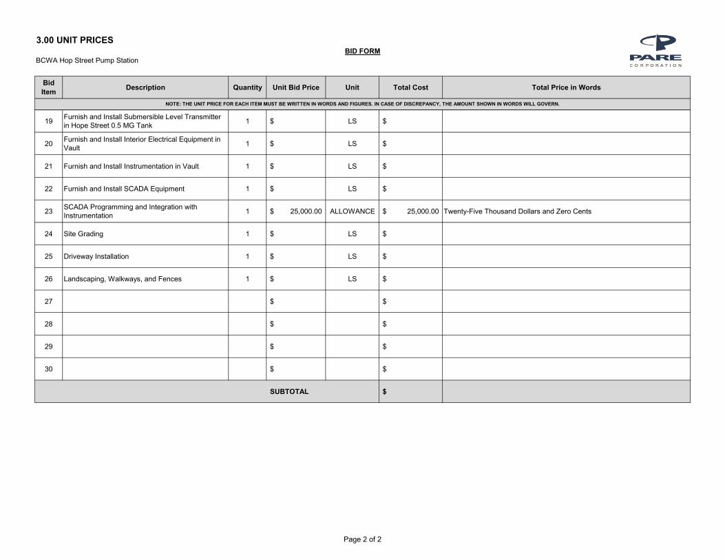
BCWA Hop Street Pump Station
Bid
ItemDescription Quantity Unit Bid Price Unit Total Cost Total Price in Words
3.00 UNIT PRICESBID FORM
NOTE: THE UNIT PRICE FOR EACH ITEM MUST BE WRITTEN IN WORDS AND FIGURES. IN CASE OF DISCREPANCY, THE AMOUNT SHOWN IN WORDS WILL GOVERN.
19Furnish and Install Submersible Level Transmitter in Hope Street 0.5 MG Tank
1 $ LS $
20Furnish and Install Interior Electrical Equipment in Vault
1 $ LS $
21 Furnish and Install Instrumentation in Vault 1 $ LS $
22 Furnish and Install SCADA Equipment 1 $ LS $
23SCADA Programming and Integration with Instrumentation
1 25,000.00$ ALLOWANCE 25,000.00$ Twenty-Five Thousand Dollars and Zero Cents
24 Site Grading 1 $ LS $
25 Driveway Installation 1 $ LS $
26 Landscaping, Walkways, and Fences 1 $ LS $
27 $ $
28 $ $
29 $ $
30 $ $
SUBTOTAL $
Page 2 of 2

BRISTOL COUNTY WATER AUTHORITY
HOPE STREET PUMP STATION
Bid Form
00310 - 4
4.00 ACCEPTANCE
This offer shall be open to acceptance and is irrevocable for sixty (60) days from the Bid closing date.
If this Bid is accepted by the Owner within the time period stated above, we will:
Execute the Agreement within ten (10) days of receipt of Notice of Award.
Furnish the required bonds within ten (10) days of receipt of Notice of Award in the form described in
Information to Bidders.
Commence work within ten (10) days after written Notice to Proceed.
If this Bid is accepted within the time stated, and we fail to commence the Work or we fail to provide the
required Bond(s), the security deposit shall be forfeited as damages to the Owner by reason of our failure,
limited in amount to the lesser of the face value of the security deposit or the difference between this Bid
and the Bid upon which the Contract is signed.
In the event our Bid is not accepted within the time stated above, the required security deposit shall be
returned to the undersigned, in accordance with the provisions of the Instructions to Bidders; unless a
mutually satisfactory arrangement is made for its retention and validity for an extended period of time.
5.00 CONTRACT TIME
If this Bid is accepted, the Bidder hereby agrees to commence WORK under this Contract on or before a
date to be specified in the NOTICE TO PROCEED and to substantially complete the PROJECT such that
the new pump station/chlorine building and valve vault are operational and substantially completed by
270 days after Notice to Proceed and to fully complete the PROJECT within 300 days of the Notice to
Proceed.
6.00 RETAINAGE
If this bid is accepted, the retainage shall be an amount equal to 10% of completed Work until 75% of the
Work has been completed. At 75% completion, if recommended by the ENGINEER and with the
concurrence of the OWNER, the retainage may be reduced to 5% by the ENGINEER and acceptable to
the OWNER, unless the ENGINEER certifies that the job is not proceeding satisfactorily, but in any event
the amounts previously retained shall not be paid to the CONTRACTOR until the Work is completed. At
75% completion, or any time thereafter when the progress of the Work, in the opinion of the ENGINEER
is not satisfactory, additional amounts may be retained, but in no event shall the total retainage be more
than 10% of the value of the Work completed. Upon satisfactory completion of the Work, any amount
retained will be paid to the CONTRACTOR.
BRISTOL COUNTY WATER AUTHORITY
HOPE STREET PUMP STATION
Bid Form
00310 - 5
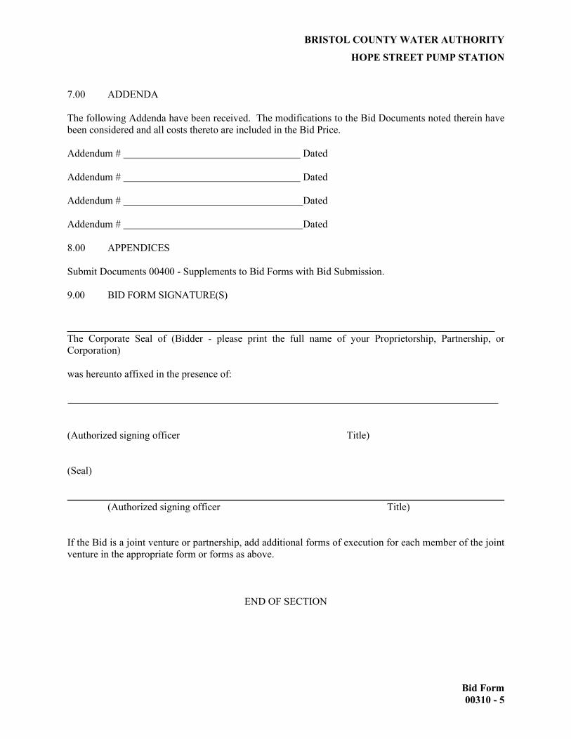
7.00 ADDENDA
The following Addenda have been received. The modifications to the Bid Documents noted therein have
been considered and all costs thereto are included in the Bid Price.
Addendum # Dated
Addendum # Dated
Addendum # Dated
Addendum # Dated
8.00 APPENDICES
Submit Documents 00400 - Supplements to Bid Forms with Bid Submission.
9.00 BID FORM SIGNATURE(S)
The Corporate Seal of (Bidder - please print the full name of your Proprietorship, Partnership, or
Corporation)
was hereunto affixed in the presence of:
(Authorized signing officer Title)
(Seal)
(Authorized signing officer Title)
If the Bid is a joint venture or partnership, add additional forms of execution for each member of the joint
venture in the appropriate form or forms as above.
END OF SECTION

BRISTOL COUNTY WATER AUTHORITY
HOPE STREET PUMP STATION
Supplements to Bid Form
00400 - 1
SECTION 00400 SUPPLEMENTS TO BID FORM
To: Bristol County Water Authority
450 Child Street
Warren, Rhode Island 02885
Project: Hope Street Pump Station
July 2021
Pare Project No. 08146.31
Date: _________________
Submitted by:
(full name)
(full address)
In accordance with Document 00100 - Instructions to Bidders, and Document 00310 - Bid Form, we include
the Supplements to Bid Form appendices listed below. The information provided shall be considered an
integral part of the Bid Form. These appendices are as follows:
Appendix A: Subcontractors: Include the names of all subcontractors, including qualifications and
experience and the portions of the work they will perform.
Appendix B: Qualifications of Bidder

BRISTOL COUNTY WATER AUTHORITY
HOPE STREET PUMP STATION
Supplements to Bid Form
00400 - 2
APPENDIX A
Herewith is the list of Subcontractors referenced in the Bid submitted by:
(Bidder)
Bristol County Water Authority
(Owner)
dated _____________________________ and, which is an integral part of the Bid Form.
The following work will be performed (or provided) by the following Subcontractors, and coordinated by us:
SECTION OF WORK NAME
Attach a listing of relevant qualifications and experience on similar projects.

BRISTOL COUNTY WATER AUTHORITY
HOPE STREET PUMP STATION
Supplements to Bid Form
00400 - 3
APPENDIX B
a) List additional Relevant Experience of firm bidding the project as it relates to projects of similar
nature and complexities as that proposed by the Bristol County Water Authority. Include: project
time frame, contact personnel, description, bid cost, final project cost (minimum 3 projects).
b) List all equipment that will be dedicated to this project. The successful bidder will be required to
dedicate the listed equipment to this project for the duration of work. No removal or substitutions
of equipment will be allowed without the express written consent of the Bristol County Water
Authority. Failure to abide by this requirement shall be cause for termination of the Contract by
the Bristol County Water Authority.
c) List all personnel, in particular the Project Manager(s), Project Superintendent(s), and Foreman(s),
who shall be directly involved and responsible for this project. The bidder also shall provide the
relevant experience of those listed. The relevant experience shall be in the installation of new
potable water pump stations and chlorine feed equipment. The successful bidder shall be required
to dedicate the listed personnel to this project for the duration of work. No removal or substitution
of personnel shall be allowed without the express written consent of the Bristol County Water
Authority. Failure to abide by this requirement shall be cause for termination of the Contract by
the Bristol County Water Authority.
Include additional sheets if necessary.

BRISTOL COUNTY WATER AUTHORITY
HOPE STREET PUMP STATION
Agreement
00500 - 1
SECTION 00500 AGREEMENT
AGREEMENT
BETWEEN OWNER AND CONTRACTOR FOR
CONSTRUCTION CONTRACT
THIS AGREEMENT is by and between the Bristol County Water Authority (Owner)
and (Contractor).
Owner and Contractor, in consideration of the mutual covenants set forth herein, agree as follows: ARTICLE 1 - WORK 1.01 Contractor shall complete all Work as specified or indicated in the Contract Documents. The limits of the Work are described in Section 01010 - General Description of the Work and includes, but is not limited to, the construction of a new pump station and chlorine dosing facility, installation of one (1) above grade hotbox, demolition of the existing Hope Street pump station building, new generator, new electrical and instrumentation, and miscellaneous site improvements. ARTICLE 2 - ENGINEER 2.01 The Project has been designed by Pare Corporation, who is to act as Owner’s representative, assume all
duties and responsibilities, and have the rights and authority assigned to Engineer in the Contract Documents in connection with the completion of the Work in accordance with the Contract Documents.
ARTICLE 3 - CONTRACT TIMES 3.01 Time of the Essence
A. All time limits for Milestones, if any, Substantial Completion, and completion and readiness for final payment as stated in the Contract Documents are of the essence of the Contract. 3.02 Days to Achieve Substantial Completion and Final Payment
A. The Work will be substantially completed, including final paving, within 270 days after the date when the Contract Time commence to run as provided in Paragraph 2.03 of the General Conditions. 3.03 Liquidated Damages
A. Contractor and Owner recognize that time is of the essence of this Agreement and that Owner will suffer financial loss if the Work is not completed within the times specified in Paragraph 4.02 above, plus any extensions thereof allowed in accordance with Article 12 of the General Conditions. The parties also recognize the delays, expense, and difficulties involved in proving in a legal or arbitration proceeding the actual loss suffered by Owner if the Work is not completed on time. Accordingly, instead of requiring any such proof, Owner and Contractor agree that as liquidated damages for delay (but not as a penalty), Contractor shall pay Owner $1,500.00 for each day that expires after the time specified in Paragraph 4.02 for Substantial Completion until the Work is substantially complete.

BRISTOL COUNTY WATER AUTHORITY
HOPE STREET PUMP STATION
Agreement
00500 - 2
ARTICLE 4 - CONTRACT PRICE A. For all Work, at the prices stated in Contractor’s Bid, attached hereto as an exhibit. ARTICLE 5 - PAYMENT PROCEDURES 5.01 Submittal and Processing of Payments
A. Contractor shall submit Applications for Payment in accordance with Article 14 of the General Conditions. Applications for Payment will be processed by Engineer as provided in the General Conditions.
5.02 Progress Payments; Retainage
A. Owner shall make progress payments on account of the Contract Price on the basis of Contractor’s Applications for Payment as recommended by the Engineer. All progress payments will be on the basis of the progress of the Work by the schedule of values provided and approved by the Engineer.
B. Prior to Substantial Completion, progress payments will be made in an amount equal to the percentage indicated below but, in each case, less the aggregate of payments previously made and less such amounts as Engineer may determine or Owner may withhold, including but not limited to liquidated damages, in accordance with Paragraph 14.02 of the General Conditions:
a. 90 percent of Work completed (with the balance being retainage); and
b. 90 percent of cost of materials and equipment not incorporated in the Work (with the balance being retainage).
2. Upon Substantial Completion, Owner shall pay an amount sufficient to increase total payments to
Contractor to 95 percent of the Work completed, less such amounts as Engineer shall determine in accordance with Paragraph 14.02.B.5 of the General Conditions.
3. Owner will make no further payments to Contractor for a period of one year following such
time as Contractor, in the opinion of Engineer, has satisfactorily completed all corrections identified in the final inspection, and has delivered, in accordance with the Contract Documents, all maintenance and operating instructions, schedules, guarantees, certificates or other evidence of insurance, certificates of inspection, marked-up record documents (as provided in Paragraph 6.12 of the General Conditions), and other documents.
6.03 Final Payment
A. Upon receipt of the final Application for Payment accompanied by Engineer’s recommendation of payment in accordance with Paragraph 14.07 of the General Conditions, Owner shall pay Contractor as provided in Paragraph 14.07 of the General Conditions the remainder of the Contract Price as recommended by Engineer as provided in said Paragraph 14.07, less any sum Owner is entitled to set off against Engineer’s recommendation, including but not limited to liquidated damages.
BRISTOL COUNTY WATER AUTHORITY
HOPE STREET PUMP STATION
Agreement
00500 - 3
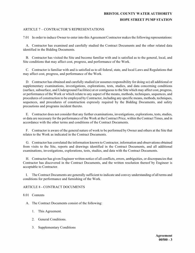
ARTICLE 7 – CONTRACTOR’S REPRESENTATIONS 7.01 In order to induce Owner to enter into this Agreement Contractor makes the following representations:
A. Contractor has examined and carefully studied the Contract Documents and the other related data identified in the Bidding Documents.
B. Contractor has visited the Site and become familiar with and is satisfied as to the general, local, and Site conditions that may affect cost, progress, and performance of the Work.
C. Contractor is familiar with and is satisfied as to all federal, state, and local Laws and Regulations that may affect cost, progress, and performance of the Work.
D. Contractor has obtained and carefully studied (or assumes responsibility for doing so) all additional or
supplementary examinations, investigations, explorations, tests, studies, and data concerning conditions (surface, subsurface, and Underground Facilities) at or contiguous to the Site which may affect cost, progress, or performance of the Work or which relate to any aspect of the means, methods, techniques, sequences, and procedures of construction to be employed by Contractor, including any specific means, methods, techniques, sequences, and procedures of construction expressly required by the Bidding Documents, and safety precautions and programs incident thereto.
E. Contractor does not consider that any further examinations, investigations, explorations, tests, studies, or data are necessary for the performance of the Work at the Contract Price, within the Contract Times, and in accordance with the other terms and conditions of the Contract Documents.
F. Contractor is aware of the general nature of work to be performed by Owner and others at the Site that relates to the Work as indicated in the Contract Documents.
G. Contractor has correlated the information known to Contractor, information and observations obtained from visits to the Site, reports and drawings identified in the Contract Documents, and all additional examinations, investigations, explorations, tests, studies, and data with the Contract Documents.
H. Contractor has given Engineer written notice of all conflicts, errors, ambiguities, or discrepancies that Contractor has discovered in the Contract Documents, and the written resolution thereof by Engineer is acceptable to Contractor. I. The Contract Documents are generally sufficient to indicate and convey understanding of all terms and conditions for performance and furnishing of the Work. ARTICLE 8 - CONTRACT DOCUMENTS 8.01 Contents
A. The Contract Documents consist of the following:
1. This Agreement.
2. General Conditions. 3. Supplementary Conditions

BRISTOL COUNTY WATER AUTHORITY
HOPE STREET PUMP STATION
Agreement
00500 - 4
4. Specifications as listed in the table of contents of the Project Manual.
5. Drawings bearing the title: Hope Street Pump Station Project, Bristol County Water Authority,
July 2021.
6. Addenda (numbers to , inclusive).
B. The documents listed in Paragraph 8.01.A are attached to this Agreement (except as expressly noted otherwise above).
C. There are no Contract Documents other than those listed above in this Article 8.
D. The Contract Documents may only be amended, modified, or supplemented as provided in Paragraph
3.04 of the General Conditions. ARTICLE 10 - MISCELLANEOUS 9.01 Terms
A. Terms used in this Agreement will have the meanings stated in the General Conditions and the Supplementary Conditions.
9.02 Assignment of Contract
A. No assignment by a party hereto of any rights under or interests in the Contract will be binding on another party hereto without the written consent of the party sought to be bound; and, specifically but without limitation, moneys that may become due and moneys that are due may not be assigned without such consent (except to the extent that the effect of this restriction may be limited by law), and unless specifically stated to the contrary in any written consent to an assignment, no assignment will release or discharge the assignor from any duty or responsibility under the Contract Documents. 9.03 Successors and Assigns
A. Owner and Contractor each binds itself, its partners, successors, assigns, and legal representatives to the other party hereto, its partners, successors, assigns, and legal representatives in respect to all covenants, agreements, and obligations contained in the Contract Documents. 9.04 Severability
A. Any provision or part of the Contract Documents held to be void or unenforceable under any Law or Regulation shall be deemed stricken, and all remaining provisions shall continue to be valid and binding upon Owner and Contractor, who agree that the Contract Documents shall be reformed to replace such stricken provision or part thereof with a valid and enforceable provision that comes as close as possible to expressing the intention of the stricken provision.
ARTICLE 10 – INDEMINITIES 10.01 Contractor agrees to indemnify and save harmless the Bristol County Water Authority (BCWA), its Agents or Employees, from and against all loss or expense (including costs of Attorney’s fees) by reason of

BRISTOL COUNTY WATER AUTHORITY
HOPE STREET PUMP STATION
Agreement
00500 - 5
liability imposed by law upon the BCWA for damages because of bodily injury, including death, at any time resulting therefrom sustained by any person or persons or on account of damage to property, including loss of use thereof, arising out of or in consequence of the performance of the Work, whether such injury to persons or damage to property is due whole or in part to the negligence of the Contractor, or his sub-contractors, their Agents or Employees. IN WITNESS WHEREOF, Owner and Contractor have signed this Agreement in four copies. One counterpart each has been delivered to Owner, Contractor, Engineer, and Agency. All portions of the Contract Documents have been signed, initialed, or identified by Owner and Contractor or identified by Engineer on their behalf. This Agreement will be effective , (which is the Effective Date of the Agreement). This Agreement shall not be effective unless and until Agency’s designated representative concurs.

BRISTOL COUNTY WATER AUTHORITY
HOPE STREET PUMP STATION
Agreement
00500 - 6
END OF DOCUMENT
OWNER: CONTRACTOR: Bristol County Water Authority
By:
Steve Coutu, P.E.
By:
Title: Executive Director, Chief Engineer Title:
[CORPORATE SEAL] [CORPORATE SEAL] Attest: Attest: Address for giving notice: Address for giving notices: Bristol County Water Authority 450 Child Street – P.O. Box 447 Warren, Rhode Island 02885 Phone: FAX:
(If Contractor is a corporation or a partnership, attach
evidence of authority to sign.)

EJCDC No. C-510 (2002 Edition) Page 1 of 1 Prepared by the Engineers' Joint Contract Documents Committee and endorsed by the Associated General Contractors of America and the Construction Specifications Institute.
Notice of Award Dated Project: Owner: Owner's Contract No.:
Contract: Engineer's Project No.:
Bidder:
Bidder's Address: (send Certified Mail, Return Receipt Requested)
You are notified that your Bid dated for the above Contract has been considered. You are the Successful Bidder and are awarded a Contract for (Indicate total Work, alternates or sections or Work awarded.) The Contract Price of your Contract is
Dollars ($ ). (Insert appropriate data if Unit Prices are used. Change language for Cost-Plus contracts.) copies of each of the proposed Contract Documents (except Drawings) accompany this Notice of Award.
sets of the Drawings will be delivered separately or otherwise made available to you immediately. You must comply with the following conditions precedent within [15] days of the date you receive this Notice of Award. 1. Deliver to the Owner [ ] fully executed counterparts of the Contract Documents. 2. Deliver with the executed Contract Documents the Contract security [Bonds] as specified in the
Instructions to Bidders (Article 20), [and] General Conditions (Paragraph 5.01) [and Supplementary Conditions (Paragraph SC-5.01).]
3. Other conditions precedent:
Failure to comply with these conditions within the time specified will entitle Owner to consider you in default, annul this Notice of Award and declare your Bid security forfeited. Within ten days after you comply with the above conditions, Owner will return to you one fully executed counterpart of the Contract Documents. Owner
By: Authorized Signature
Title Copy to Engineer
EJCDC No. C-550 (2002 Edition) Page 1 of 1 Prepared by the Engineers' Joint Contract Documents Committee and endorsed by the Associated General Contractors of America and the Construction Specifications Institute.
Notice to Proceed
Dated
Project: Owner: Owner's Contract No.:
Contract: Engineer's Project No.:
Contractor:
Contractor's Address: [send Certified Mail, Return Receipt Requested]
You are notified that the Contract Times under the above contract will commence to run on . On or before that date, you are to start performing your obligations under the Contract Documents. In accordance with Article 4 of the Agreement, the date of Substantial Completion is , and the date of readiness for final payment is
[(or) the number of days to achieve Substantial Completion is , and the number of days to achieve readiness for final payment is ].
Before you may start any Work at the Site, Paragraph 2.01.B of the General Conditions provides that you and Owner must each deliver to the other (with copies to Engineer and other identified additional insureds) certificates of insurance which each is required to purchase and maintain in accordance with the Contract Documents.
Also, before you may start any Work at the Site, you must [add other requirements]:
Owner
Given by:
Authorized Signature
Title
Date
Copy to Engineer
00610-1
PERFORMANCE BOND
Any singular reference to Contractor, Surety, Owner, or other party shall be considered plural where applicable. CONTRACTOR (Name and Address): SURETY (Name and Address of Principal Place of Business): OWNER (Name and Address): CONTRACT Date: Amount: Description (Name and Location): BOND Bond Number: Date (Not earlier than Contract Date): Amount: Modifications to this Bond Form: Surety and Contractor, intending to be legally bound hereby, subject to the terms printed on the reverse side hereof, do each cause this Performance Bond to be duly executed on its behalf by its authorized officer, agent, or representative.
CONTRACTOR AS PRINCIPAL SURETY Company: Signature: (Seal) (Seal) Name and Title: Surety’s Name and Corporate Seal By: Signature and Title (Attach Power of Attorney) (Space is provided below for signatures of additional parties, if required.)
Attest: Signature and Title CONTRACTOR AS PRINCIPAL SURETY Company: Signature: (Seal) (Seal) Name and Title: Surety’s Name and Corporate Seal By: Signature and Title (Attach Power of Attorney) Attest: Signature and Title:
EJCDC No. C-610 (2002 Edition) Originally prepared through the joint efforts of the Surety Association of America, Engineers Joint Contract Documents Committee, the Associated General Contractors of America, and the American Institute of Architects.
00615-1
PAYMENT BOND
Any singular reference to Contractor, Surety, Owner, or other party shall be considered plural where applicable. CONTRACTOR (Name and Address): SURETY (Name and Address of Principal Place of Business): OWNER (Name and Address): CONTRACT Date: Amount: Description (Name and Location): BOND Bond Number: Date (Not earlier than Contract Date): Amount: Modifications to this Bond Form: Surety and Contractor, intending to be legally bound hereby, subject to the terms printed on the reverse side hereof, do each cause this Payment Bond to be duly executed on its behalf by its authorized officer, agent, or representative.
CONTRACTOR AS PRINCIPAL SURETY Company: Signature: (Seal) (Seal) Name and Title: Surety’s Name and Corporate Seal By: Signature and Title (Attach Power of Attorney) (Space is provided below for signatures of additional parties, if required.)
Attest: Signature and Title CONTRACTOR AS PRINCIPAL SURETY Company: Signature: (Seal) (Seal) Name and Title: Surety’s Name and Corporate Seal By: Signature and Title (Attach Power of Attorney) Attest: Signature and Title:
EJCDC No. C-615 (2002 Edition) Originally prepared through the joint efforts of the Surety Association of America, Engineers Joint Contract Documents Committee, the Associated General Contractors of America, the American Institute of Architects, the American Subcontractors Association, and the Associated Specialty Contractors.

00615-2
1. Contractor and Surety, jointly and severally, bind themselves, their heirs, executors, administrators, successors, and assigns to Owner to pay for labor, materials, and equipment furnished by Claimants for use in the performance of the Contract, which is incorporated herein by reference. 2. With respect to Owner, this obligation shall be null and void if Contractor:
2.1. Promptly makes payment, directly or indirectly, for all sums due Claimants, and
2.2. Defends, indemnifies, and holds harmless Owner from all claims,
demands, liens, or suits alleging non-payment by Contractor by any person or entity who furnished labor, materials, or equipment for use in the performance of the Contract, provided Owner has promptly notified Contractor and Surety (at the addresses described in Paragraph 12) of any claims, demands, liens, or suits and tendered defense of such claims, demands, liens, or suits to Contractor and Surety, and provided there is no Owner Default.
3. With respect to Claimants, this obligation shall be null and void if Contractor promptly makes payment, directly or indirectly, for all sums due. 4. Surety shall have no obligation to Claimants under this Bond until:
4.1. Claimants who are employed by or have a direct contract with Contractor have given notice to Surety (at the addresses described in Paragraph 12) and sent a copy, or notice thereof, to Owner, stating that a claim is being made under this Bond and, with substantial accuracy, the amount of the claim.
4.2. Claimants who do not have a direct contract with Contractor:
1. Have furnished written notice to Contractor and sent a copy, or
notice thereof, to Owner, within 90 days after having last performed labor or last furnished materials or equipment included in the claim stating, with substantial accuracy, the amount of the claim and the name of the party to whom the materials or equipment were furnished or supplied, or for whom the labor was done or performed; and
2. Have either received a rejection in whole or in part from Contractor,
or not received within 30 days of furnishing the above notice any communication from Contractor by which Contractor had indicated the claim will be paid directly or indirectly; and
3. Not having been paid within the above 30 days, have sent a written
notice to Surety and sent a copy, or notice thereof, to Owner, stating that a claim is being made under this Bond and enclosing a copy of the previous written notice furnished to Contractor.
5. If a notice by a Claimant required by Paragraph 4 is provided by Owner to Contractor or to Surety, that is sufficient compliance. 6. When a Claimant has satisfied the conditions of Paragraph 4, the Surety shall promptly and at Surety's expense take the following actions:
6.1. Send an answer to that Claimant, with a copy to Owner, within 45 days after receipt of the claim, stating the amounts that are undisputed and the basis for challenging any amounts that are disputed.
6.2. Pay or arrange for payment of any undisputed amounts.
7. Surety's total obligation shall not exceed the amount of this Bond, and the amount of this Bond shall be credited for any payments made in good faith by Surety.
8. Amounts owed by Owner to Contractor under the Contract shall be used for the performance of the Contract and to satisfy claims, if any, under any performance bond. By Contractor furnishing and Owner accepting this Bond, they agree that all funds earned by Contractor in the performance of the Contract are dedicated to satisfy obligations of Contractor and Surety under this Bond, subject to Owner's priority to use the funds for the completion of the Work. 9. Surety shall not be liable to Owner, Claimants, or others for obligations of Contractor that are unrelated to the Contract. Owner shall not be liable for payment of any costs or expenses of any Claimant under this Bond, and shall have under this Bond no obligations to make payments to, give notices on behalf of, or otherwise have obligations to Claimants under this Bond. 10. Surety hereby waives notice of any change, including changes of time, to the Contract or to related Subcontracts, purchase orders and other obligations. 11. No suit or action shall be commenced by a Claimant under this Bond other than in a court of competent jurisdiction in the location in which the Work or part of the Work is located or after the expiration of one year from the date (1) on which the Claimant gave the notice required by Paragraph 4.1 or Paragraph 4.2.3, or (2) on which the last labor or service was performed by anyone or the last materials or equipment were furnished by anyone under the Construction Contract, whichever of (1) or (2) first occurs. If the provisions of this paragraph are void or prohibited by law, the minimum period of limitation available to sureties as a defense in the jurisdiction of the suit shall be applicable. 12. Notice to Surety, Owner, or Contractor shall be mailed or delivered to the addresses shown on the signature page. Actual receipt of notice by Surety, Owner, or Contractor, however accomplished, shall be sufficient compliance as of the date received at the address shown on the signature page. 13. When this Bond has been furnished to comply with a statutory requirement in the location where the Contract was to be performed, any provision in this Bond conflicting with said statutory requirement shall be deemed deleted herefrom and provisions conforming to such statutory requirement shall be deemed incorporated herein. The intent is that this Bond shall be construed as a statutory Bond and not as a common law bond. 14. Upon request of any person or entity appearing to be a potential beneficiary of this Bond, Contractor shall promptly furnish a copy of this Bond or shall permit a copy to be made. 15. DEFINITIONS
15.1. Claimant: An individual or entity having a direct contract with Contractor, or with a first-tier subcontractor of Contractor, to furnish labor, materials, or equipment for use in the performance of the Contract. The intent of this Bond shall be to include without limitation in the terms "labor, materials or equipment" that part of water, gas, power, light, heat, oil, gasoline, telephone service, or rental equipment used in the Contract, architectural and engineering services required for performance of the Work of Contractor and Contractor's Subcontractors, and all other items for which a mechanic's lien may be asserted in the jurisdiction where the labor, materials, or equipment were furnished.
15.2. Contract: The agreement between Owner and Contractor identified on
the signature page, including all Contract Documents and changes thereto.
15.3. Owner Default: Failure of Owner, which has neither been remedied nor
waived, to pay Contractor as required by the Contract or to perform and complete or comply with the other terms thereof.
FOR INFORMATION ONLY – Name, Address and Telephone Surety Agency or Broker: Owner’s Representative (engineer or other party):

EJCDC C-700 Standard General Conditions of the Construction Contract Copyright © 2007 National Society of Professional Engineers for EJCDC. All rights reserved.
STANDARD GENERAL CONDITIONS OF THE CONSTRUCTION CONTRACT
Prepared by
ENGINEERS JOINT CONTRACT DOCUMENTS COMMITTEE
and
Issued and Published Jointly by
AMERICAN COUNCIL OF ENGINEERING COMPANIES ______________________
ASSOCIATED GENERAL CONTRACTORS OF AMERICA
______________________
AMERICAN SOCIETY OF CIVIL ENGINEERS _______________________
PROFESSIONAL ENGINEERS IN PRIVATE PRACTICE
A Practice Division of the NATIONAL SOCIETY OF PROFESSIONAL ENGINEERS
Endorsed by
CONSTRUCTION SPECIFICATIONS INSTITUTE

EJCDC C-700 Standard General Conditions of the Construction Contract Copyright © 2007 National Society of Professional Engineers for EJCDC. All rights reserved.
Copyright © 2007 National Society of Professional Engineers
1420 King Street, Alexandria, VA 22314-2794 (703) 684-2882 www.nspe.org
American Council of Engineering Companies
1015 15th Street N.W., Washington, DC 20005 (202) 347-7474 www.acec.org
American Society of Civil Engineers
1801 Alexander Bell Drive, Reston, VA 20191-4400 (800) 548-2723 www.asce.org
Associated General Contractors of America
2300 Wilson Boulevard, Suite 400, Arlington, VA 22201-3308 (703) 548-3118 www.agc.org
The copyright for this EJCDC document is owned jointly by the four EJCDC sponsoring organizations and held in trust for their benefit by NSPE.

EJCDC C-700 Standard General Conditions of the Construction Contract Copyright © 2007 National Society of Professional Engineers for EJCDC. All rights reserved.
Page i
STANDARD GENERAL CONDITIONS OF THE CONSTRUCTION CONTRACT
TABLE OF CONTENTS
Page
Article 1 – Definitions and Terminology .......................................................................................................... 1 1.01 Defined Terms ............................................................................................................................... 1 1.02 Terminology .................................................................................................................................. 5
Article 2 – Preliminary Matters ......................................................................................................................... 6 2.01 Copies of Documents .................................................................................................................... 6 2.02 Commencement of Contract Times; Notice to Proceed .............................................................. 6 2.03 Starting the Work .......................................................................................................................... 6 2.04 Before Starting Construction ........................................................................................................ 6 2.05 Preconstruction Conference; Designation of Authorized Representatives ................................. 7 2.06 Initial Acceptance of Schedules ................................................................................................... 7
Article 3 – Contract Documents: Intent, Amending, Reuse ............................................................................ 8 3.01 Intent .............................................................................................................................................. 8 3.02 Reference Standards ..................................................................................................................... 8 3.03 Reporting and Resolving Discrepancies ...................................................................................... 8 3.04 Amending and Supplementing Contract Documents .................................................................. 9 3.05 Reuse of Documents ..................................................................................................................... 9 3.06 Electronic Data ............................................................................................................................ 10
Article 4 – Availability of Lands; Subsurface and Physical Conditions; Hazardous Environmental Conditions; Reference Points .......................................................................................................... 10
4.01 Availability of Lands .................................................................................................................. 10 4.02 Subsurface and Physical Conditions .......................................................................................... 11 4.03 Differing Subsurface or Physical Conditions ............................................................................. 11 4.04 Underground Facilities ............................................................................................................... 12 4.05 Reference Points ......................................................................................................................... 13 4.06 Hazardous Environmental Condition at Site .............................................................................. 14
Article 5 – Insurance ........................................................................................................................................ 15 5.01 Certificates of Insurance ............................................................................................................. 15 5.02 Contractor’s Insurance ................................................................................................................ 16 5.03 Owner’s Liability Insurance ....................................................................................................... 17 5.04 Property Insurance ...................................................................................................................... 17 5.05 Waiver of Rights ......................................................................................................................... 19 5.06 Receipt and Application of Insurance Proceeds ........................................................................ 20 5.07 Acceptance of Insurance; Option to Replace ............................................................................. 20 5.08 Partial Utilization, Acknowledgment of Property Insurer ......................................................... 20
EJCDC C-700 Standard General Conditions of the Construction Contract Copyright © 2007 National Society of Professional Engineers for EJCDC. All rights reserved.
Page ii
Article 6 – Contractor’s Responsibilities ........................................................................................................ 20 6.01 Supervision and Superintendence .............................................................................................. 20 6.02 Labor; Working Hours ................................................................................................................ 21 6.03 Services, Materials, and Equipment ........................................................................................... 21 6.04 Progress Schedule ....................................................................................................................... 21 6.05 Substitutes and “Or-Equals” ....................................................................................................... 22 6.06 Concerning Subcontractors, Suppliers, and Others ................................................................... 24 6.07 Patent Fees and Royalties ........................................................................................................... 25 6.08 Permits ......................................................................................................................................... 26 6.09 Laws and Regulations ................................................................................................................. 26 6.10 Taxes ........................................................................................................................................... 26 6.11 Use of Site and Other Areas ....................................................................................................... 26 6.12 Record Documents ...................................................................................................................... 27 6.13 Safety and Protection .................................................................................................................. 28 6.14 Safety Representative ................................................................................................................. 29 6.15 Hazard Communication Programs ............................................................................................. 29 6.16 Emergencies ................................................................................................................................ 29 6.17 Shop Drawings and Samples ...................................................................................................... 29 6.18 Continuing the Work .................................................................................................................. 31 6.19 Contractor’s General Warranty and Guarantee .......................................................................... 31 6.20 Indemnification ........................................................................................................................... 32 6.21 Delegation of Professional Design Services .............................................................................. 32
Article 7 – Other Work at the Site ................................................................................................................... 33 7.01 Related Work at Site ................................................................................................................... 33 7.02 Coordination ................................................................................................................................ 34 7.03 Legal Relationships ..................................................................................................................... 34
Article 8 – Owner’s Responsibilities .............................................................................................................. 34 8.01 Communications to Contractor ................................................................................................... 34 8.02 Replacement of Engineer ............................................................................................................ 34 8.03 Furnish Data ................................................................................................................................ 34 8.04 Pay When Due ............................................................................................................................ 35 8.05 Lands and Easements; Reports and Tests .................................................................................. 35 8.06 Insurance ..................................................................................................................................... 35 8.07 Change Orders ............................................................................................................................. 35 8.08 Inspections, Tests, and Approvals .............................................................................................. 35 8.09 Limitations on Owner’s Responsibilities ................................................................................... 35 8.10 Undisclosed Hazardous Environmental Condition .................................................................... 35 8.11 Evidence of Financial Arrangements ......................................................................................... 35 8.12 Compliance with Safety Program ............................................................................................... 35
Article 9 – Engineer’s Status During Construction ........................................................................................ 36 9.01 Owner’s Representative .............................................................................................................. 36 9.02 Visits to Site ................................................................................................................................ 36 9.03 Project Representative ................................................................................................................ 36 9.04 Authorized Variations in Work .................................................................................................. 36 9.05 Rejecting Defective Work .......................................................................................................... 37

EJCDC C-700 Standard General Conditions of the Construction Contract Copyright © 2007 National Society of Professional Engineers for EJCDC. All rights reserved.
Page iii
9.06 Shop Drawings, Change Orders and Payments ......................................................................... 37 9.07 Determinations for Unit Price Work .......................................................................................... 37 9.08 Decisions on Requirements of Contract Documents and Acceptability of Work .................... 37 9.09 Limitations on Engineer’s Authority and Responsibilities ........................................................ 38 9.10 Compliance with Safety Program ............................................................................................... 38
Article 10 – Changes in the Work; Claims ..................................................................................................... 38 10.01 Authorized Changes in the Work ............................................................................................... 38 10.02 Unauthorized Changes in the Work ........................................................................................... 39 10.03 Execution of Change Orders ....................................................................................................... 39 10.04 Claims .......................................................................................................................................... 39
Article 11 – Cost of the Work; Allowances; Unit Price Work ....................................................................... 40 11.01 Cost of the Work ......................................................................................................................... 40 11.02 Allowances .................................................................................................................................. 43 11.03 Unit Price Work .......................................................................................................................... 43
Article 12 – Change of Contract Price; Change of Contract Times ............................................................... 44 12.01 Change of Contract Price ............................................................................................................ 44 12.02 Change of Contract Times .......................................................................................................... 45 12.03 Delays .......................................................................................................................................... 45
Article 13 – Tests and Inspections; Correction, Removal or Acceptance of Defective Work ...................... 46 13.01 Notice of Defects ........................................................................................................................ 46 13.02 Access to Work ........................................................................................................................... 46 13.03 Tests and Inspections .................................................................................................................. 46 13.04 Uncovering Work ....................................................................................................................... 47 13.05 Owner May Stop the Work ......................................................................................................... 48 13.06 Correction or Removal of Defective Work ................................................................................ 48 13.07 Correction Period ........................................................................................................................ 48 13.08 Acceptance of Defective Work .................................................................................................. 49 13.09 Owner May Correct Defective Work ......................................................................................... 49
Article 14 – Payments to Contractor and Completion .................................................................................... 50 14.01 Schedule of Values ..................................................................................................................... 50 14.02 Progress Payments ...................................................................................................................... 50 14.03 Contractor’s Warranty of Title ................................................................................................... 53 14.04 Substantial Completion ............................................................................................................... 53 14.05 Partial Utilization ........................................................................................................................ 54 14.06 Final Inspection ........................................................................................................................... 54 14.07 Final Payment ............................................................................................................................. 55 14.08 Final Completion Delayed .......................................................................................................... 56 14.09 Waiver of Claims ........................................................................................................................ 56
Article 15 – Suspension of Work and Termination ........................................................................................ 56 15.01 Owner May Suspend Work ........................................................................................................ 56 15.02 Owner May Terminate for Cause ............................................................................................... 56 15.03 Owner May Terminate For Convenience ................................................................................... 58 15.04 Contractor May Stop Work or Terminate .................................................................................. 58
EJCDC C-700 Standard General Conditions of the Construction Contract Copyright © 2007 National Society of Professional Engineers for EJCDC. All rights reserved.
Page iv
Article 16 – Dispute Resolution ...................................................................................................................... 59 16.01 Methods and Procedures ............................................................................................................. 59
Article 17 – Miscellaneous .............................................................................................................................. 59 17.01 Giving Notice .............................................................................................................................. 59 17.02 Computation of Times ................................................................................................................ 59 17.03 Cumulative Remedies ................................................................................................................. 60 17.04 Survival of Obligations ............................................................................................................... 60 17.05 Controlling Law .......................................................................................................................... 60 17.06 Headings ...................................................................................................................................... 60

EJCDC C-700 Standard General Conditions of the Construction Contract Copyright © 2007 National Society of Professional Engineers for EJCDC. All rights reserved.
Page 1 of 64
ARTICLE 1 – DEFINITIONS AND TERMINOLOGY
1.01 Defined Terms
A. Wherever used in the Bidding Requirements or Contract Documents and printed with initial capital letters, the terms listed below will have the meanings indicated which are applicable to both the singular and plural thereof. In addition to terms specifically defined, terms with initial capital letters in the Contract Documents include references to identified articles and paragraphs, and the titles of other documents or forms.
1. Addenda—Written or graphic instruments issued prior to the opening of Bids which clarify, correct, or change the Bidding Requirements or the proposed Contract Documents.
2. Agreement—The written instrument which is evidence of the agreement between Owner and Contractor covering the Work.
3. Application for Payment—The form acceptable to Engineer which is to be used by Contractor during the course of the Work in requesting progress or final payments and which is to be accompanied by such supporting documentation as is required by the Contract Documents.
4. Asbestos—Any material that contains more than one percent asbestos and is friable or is releasing asbestos fibers into the air above current action levels established by the United States Occupational Safety and Health Administration.
5. Bid—The offer or proposal of a Bidder submitted on the prescribed form setting forth the prices for the Work to be performed.
6. Bidder—The individual or entity who submits a Bid directly to Owner.
7. Bidding Documents—The Bidding Requirements and the proposed Contract Documents (including all Addenda).
8. Bidding Requirements—The advertisement or invitation to bid, Instructions to Bidders, Bid security of acceptable form, if any, and the Bid Form with any supplements.
9. Change Order—A document recommended by Engineer which is signed by Contractor and Owner and authorizes an addition, deletion, or revision in the Work or an adjustment in the Contract Price or the Contract Times, issued on or after the Effective Date of the Agreement.
10. Claim—A demand or assertion by Owner or Contractor seeking an adjustment of Contract Price or Contract Times, or both, or other relief with respect to the terms of the Contract. A demand for money or services by a third party is not a Claim.
11. Contract—The entire and integrated written agreement between the Owner and Contractor concerning the Work. The Contract supersedes prior negotiations, representations, or agreements, whether written or oral.

EJCDC C-700 Standard General Conditions of the Construction Contract Copyright © 2007 National Society of Professional Engineers for EJCDC. All rights reserved.
Page 2 of 64
12. Contract Documents—Those items so designated in the Agreement. Only printed or hard copies of the items listed in the Agreement are Contract Documents. Approved Shop Drawings, other Contractor submittals, and the reports and drawings of subsurface and physical conditions are not Contract Documents.
13. Contract Price—The moneys payable by Owner to Contractor for completion of the Work in accordance with the Contract Documents as stated in the Agreement (subject to the provisions of Paragraph 11.03 in the case of Unit Price Work).
14. Contract Times—The number of days or the dates stated in the Agreement to: (i) achieve Milestones, if any; (ii) achieve Substantial Completion; and (iii) complete the Work so that it is ready for final payment as evidenced by Engineer’s written recommendation of final payment.
15. Contractor—The individual or entity with whom Owner has entered into the Agreement.
16. Cost of the Work—See Paragraph 11.01 for definition.
17. Drawings—That part of the Contract Documents prepared or approved by Engineer which graphically shows the scope, extent, and character of the Work to be performed by Contractor. Shop Drawings and other Contractor submittals are not Drawings as so defined.
18. Effective Date of the Agreement—The date indicated in the Agreement on which it becomes effective, but if no such date is indicated, it means the date on which the Agreement is signed and delivered by the last of the two parties to sign and deliver.
19. Engineer—The individual or entity named as such in the Agreement.
20. Field Order—A written order issued by Engineer which requires minor changes in the Work but which does not involve a change in the Contract Price or the Contract Times.
21. General Requirements—Sections of Division 1 of the Specifications.
22. Hazardous Environmental Condition—The presence at the Site of Asbestos, PCBs, Petroleum, Hazardous Waste, or Radioactive Material in such quantities or circumstances that may present a substantial danger to persons or property exposed thereto.
23. Hazardous Waste—The term Hazardous Waste shall have the meaning provided in Section 1004 of the Solid Waste Disposal Act (42 USC Section 6903) as amended from time to time.
24. Laws and Regulations; Laws or Regulations—Any and all applicable laws, rules, regulations, ordinances, codes, and orders of any and all governmental bodies, agencies, authorities, and courts having jurisdiction.
25. Liens—Charges, security interests, or encumbrances upon Project funds, real property, or personal property.
26. Milestone—A principal event specified in the Contract Documents relating to an intermediate completion date or time prior to Substantial Completion of all the Work.

EJCDC C-700 Standard General Conditions of the Construction Contract Copyright © 2007 National Society of Professional Engineers for EJCDC. All rights reserved.
Page 3 of 64
27. Notice of Award—The written notice by Owner to the Successful Bidder stating that upon timely compliance by the Successful Bidder with the conditions precedent listed therein, Owner will sign and deliver the Agreement.
28. Notice to Proceed—A written notice given by Owner to Contractor fixing the date on which the Contract Times will commence to run and on which Contractor shall start to perform the Work under the Contract Documents.
29. Owner—The individual or entity with whom Contractor has entered into the Agreement and for whom the Work is to be performed.
30. PCBs—Polychlorinated biphenyls.
31. Petroleum—Petroleum, including crude oil or any fraction thereof which is liquid at standard conditions of temperature and pressure (60 degrees Fahrenheit and 14.7 pounds per square inch absolute), such as oil, petroleum, fuel oil, oil sludge, oil refuse, gasoline, kerosene, and oil mixed with other non-Hazardous Waste and crude oils.
32. Progress Schedule—A schedule, prepared and maintained by Contractor, describing the sequence and duration of the activities comprising the Contractor’s plan to accomplish the Work within the Contract Times.
33. Project—The total construction of which the Work to be performed under the Contract Documents may be the whole, or a part.
34. Project Manual—The bound documentary information prepared for bidding and constructing the Work. A listing of the contents of the Project Manual, which may be bound in one or more volumes, is contained in the table(s) of contents.
35. Radioactive Material—Source, special nuclear, or byproduct material as defined by the Atomic Energy Act of 1954 (42 USC Section 2011 et seq.) as amended from time to time.
36. Resident Project Representative—The authorized representative of Engineer who may be assigned to the Site or any part thereof.
37. Samples—Physical examples of materials, equipment, or workmanship that are representative of some portion of the Work and which establish the standards by which such portion of the Work will be judged.
38. Schedule of Submittals—A schedule, prepared and maintained by Contractor, of required submittals and the time requirements to support scheduled performance of related construction activities.
39. Schedule of Values—A schedule, prepared and maintained by Contractor, allocating portions of the Contract Price to various portions of the Work and used as the basis for reviewing Contractor’s Applications for Payment.

EJCDC C-700 Standard General Conditions of the Construction Contract Copyright © 2007 National Society of Professional Engineers for EJCDC. All rights reserved.
Page 4 of 64
40. Shop Drawings—All drawings, diagrams, illustrations, schedules, and other data or information which are specifically prepared or assembled by or for Contractor and submitted by Contractor to illustrate some portion of the Work.
41. Site—Lands or areas indicated in the Contract Documents as being furnished by Owner upon which the Work is to be performed, including rights-of-way and easements for access thereto, and such other lands furnished by Owner which are designated for the use of Contractor.
42. Specifications—That part of the Contract Documents consisting of written requirements for materials, equipment, systems, standards and workmanship as applied to the Work, and certain administrative requirements and procedural matters applicable thereto.
43. Subcontractor—An individual or entity having a direct contract with Contractor or with any other Subcontractor for the performance of a part of the Work at the Site.
44. Substantial Completion—The time at which the Work (or a specified part thereof) has progressed to the point where, in the opinion of Engineer, the Work (or a specified part thereof) is sufficiently complete, in accordance with the Contract Documents, so that the Work (or a specified part thereof) can be utilized for the purposes for which it is intended. The terms “substantially complete” and “substantially completed” as applied to all or part of the Work refer to Substantial Completion thereof.
45. Successful Bidder—The Bidder submitting a responsive Bid to whom Owner makes an award.
46. Supplementary Conditions—That part of the Contract Documents which amends or supplements these General Conditions.
47. Supplier—A manufacturer, fabricator, supplier, distributor, materialman, or vendor having a direct contract with Contractor or with any Subcontractor to furnish materials or equipment to be incorporated in the Work by Contractor or Subcontractor.
48. Underground Facilities—All underground pipelines, conduits, ducts, cables, wires, manholes, vaults, tanks, tunnels, or other such facilities or attachments, and any encasements containing such facilities, including those that convey electricity, gases, steam, liquid petroleum products, telephone or other communications, cable television, water, wastewater, storm water, other liquids or chemicals, or traffic or other control systems.
49. Unit Price Work—Work to be paid for on the basis of unit prices.
50. Work—The entire construction or the various separately identifiable parts thereof required to be provided under the Contract Documents. Work includes and is the result of performing or providing all labor, services, and documentation necessary to produce such construction, and furnishing, installing, and incorporating all materials and equipment into such construction, all as required by the Contract Documents.
51. Work Change Directive—A written statement to Contractor issued on or after the Effective Date of the Agreement and signed by Owner and recommended by Engineer ordering an

EJCDC C-700 Standard General Conditions of the Construction Contract Copyright © 2007 National Society of Professional Engineers for EJCDC. All rights reserved.
Page 5 of 64
addition, deletion, or revision in the Work, or responding to differing or unforeseen subsurface or physical conditions under which the Work is to be performed or to emergencies. A Work Change Directive will not change the Contract Price or the Contract Times but is evidence that the parties expect that the change ordered or documented by a Work Change Directive will be incorporated in a subsequently issued Change Order following negotiations by the parties as to its effect, if any, on the Contract Price or Contract Times.
1.02 Terminology
A. The words and terms discussed in Paragraph 1.02.B through F are not defined but, when used in the Bidding Requirements or Contract Documents, have the indicated meaning.
B. Intent of Certain Terms or Adjectives:
1. The Contract Documents include the terms “as allowed,” “as approved,” “as ordered,” “as directed” or terms of like effect or import to authorize an exercise of professional judgment by Engineer. In addition, the adjectives “reasonable,” “suitable,” “acceptable,” “proper,” “satisfactory,” or adjectives of like effect or import are used to describe an action or determination of Engineer as to the Work. It is intended that such exercise of professional judgment, action, or determination will be solely to evaluate, in general, the Work for compliance with the information in the Contract Documents and with the design concept of the Project as a functioning whole as shown or indicated in the Contract Documents (unless there is a specific statement indicating otherwise). The use of any such term or adjective is not intended to and shall not be effective to assign to Engineer any duty or authority to supervise or direct the performance of the Work, or any duty or authority to undertake responsibility contrary to the provisions of Paragraph 9.09 or any other provision of the Contract Documents.
C. Day:
1. The word “day” means a calendar day of 24 hours measured from midnight to the next midnight.
D. Defective:
1. The word “defective,” when modifying the word “Work,” refers to Work that is unsatisfactory, faulty, or deficient in that it:
a. does not conform to the Contract Documents; or
b. does not meet the requirements of any applicable inspection, reference standard, test, or approval referred to in the Contract Documents; or
c. has been damaged prior to Engineer’s recommendation of final payment (unless responsibility for the protection thereof has been assumed by Owner at Substantial Completion in accordance with Paragraph 14.04 or 14.05).
E. Furnish, Install, Perform, Provide:

EJCDC C-700 Standard General Conditions of the Construction Contract Copyright © 2007 National Society of Professional Engineers for EJCDC. All rights reserved.
Page 6 of 64
1. The word “furnish,” when used in connection with services, materials, or equipment, shall mean to supply and deliver said services, materials, or equipment to the Site (or some other specified location) ready for use or installation and in usable or operable condition.
2. The word “install,” when used in connection with services, materials, or equipment, shall mean to put into use or place in final position said services, materials, or equipment complete and ready for intended use.
3. The words “perform” or “provide,” when used in connection with services, materials, or equipment, shall mean to furnish and install said services, materials, or equipment complete and ready for intended use.
4. When “furnish,” “install,” “perform,” or “provide” is not used in connection with services, materials, or equipment in a context clearly requiring an obligation of Contractor, “provide” is implied.
F. Unless stated otherwise in the Contract Documents, words or phrases that have a well-known technical or construction industry or trade meaning are used in the Contract Documents in accordance with such recognized meaning.
ARTICLE 2 – PRELIMINARY MATTERS
2.01 Copies of Documents
A. Owner shall furnish to Contractor up to ten printed or hard copies of the Drawings and Project Manual. Additional copies will be furnished upon request at the cost of reproduction.
2.02 Commencement of Contract Times; Notice to Proceed
A. The Contract Times will commence to run on the thirtieth day after the Effective Date of the Agreement or, if a Notice to Proceed is given, on the day indicated in the Notice to Proceed. A Notice to Proceed may be given at any time within 30 days after the Effective Date of the Agreement. In no event will the Contract Times commence to run later than the sixtieth day after the day of Bid opening or the thirtieth day after the Effective Date of the Agreement, whichever date is earlier.
2.03 Starting the Work
A. Contractor shall start to perform the Work on the date when the Contract Times commence to run. No Work shall be done at the Site prior to the date on which the Contract Times commence to run.
2.04 Before Starting Construction
A. Preliminary Schedules: Within 10 days after the Effective Date of the Agreement (unless otherwise specified in the General Requirements), Contractor shall submit to Engineer for timely review:

EJCDC C-700 Standard General Conditions of the Construction Contract Copyright © 2007 National Society of Professional Engineers for EJCDC. All rights reserved.
Page 7 of 64
1. a preliminary Progress Schedule indicating the times (numbers of days or dates) for starting and completing the various stages of the Work, including any Milestones specified in the Contract Documents;
2. a preliminary Schedule of Submittals; and
3. a preliminary Schedule of Values for all of the Work which includes quantities and prices of items which when added together equal the Contract Price and subdivides the Work into component parts in sufficient detail to serve as the basis for progress payments during performance of the Work. Such prices will include an appropriate amount of overhead and profit applicable to each item of Work.
2.05 Preconstruction Conference; Designation of Authorized Representatives
A. Before any Work at the Site is started, a conference attended by Owner, Contractor, Engineer, and others as appropriate will be held to establish a working understanding among the parties as to the Work and to discuss the schedules referred to in Paragraph 2.05.A, procedures for handling Shop Drawings and other submittals, processing Applications for Payment, and maintaining required records.
B. At this conference Owner and Contractor each shall designate, in writing, a specific individual to act as its authorized representative with respect to the services and responsibilities under the Contract. Such individuals shall have the authority to transmit instructions, receive information, render decisions relative to the Contract, and otherwise act on behalf of each respective party.
2.06 Initial Acceptance of Schedules
A. At least 10 days before submission of the first Application for Payment a conference attended by Contractor, Engineer, and others as appropriate will be held to review for acceptability to Engineer as provided below the schedules submitted in accordance with Paragraph 2.05.A. Contractor shall have an additional 10 days to make corrections and adjustments and to complete and resubmit the schedules. No progress payment shall be made to Contractor until acceptable schedules are submitted to Engineer.
1. The Progress Schedule will be acceptable to Engineer if it provides an orderly progression of the Work to completion within the Contract Times. Such acceptance will not impose on Engineer responsibility for the Progress Schedule, for sequencing, scheduling, or progress of the Work, nor interfere with or relieve Contractor from Contractor’s full responsibility therefor.
2. Contractor’s Schedule of Submittals will be acceptable to Engineer if it provides a workable arrangement for reviewing and processing the required submittals.
3. Contractor’s Schedule of Values will be acceptable to Engineer as to form and substance if it provides a reasonable allocation of the Contract Price to component parts of the Work.
EJCDC C-700 Standard General Conditions of the Construction Contract Copyright © 2007 National Society of Professional Engineers for EJCDC. All rights reserved.
Page 8 of 64
ARTICLE 3 – CONTRACT DOCUMENTS: INTENT, AMENDING, REUSE
3.01 Intent
A. The Contract Documents are complementary; what is required by one is as binding as if required by all.
B. It is the intent of the Contract Documents to describe a functionally complete project (or part thereof) to be constructed in accordance with the Contract Documents. Any labor, documentation, services, materials, or equipment that reasonably may be inferred from the Contract Documents or from prevailing custom or trade usage as being required to produce the indicated result will be provided whether or not specifically called for, at no additional cost to Owner.
C. Clarifications and interpretations of the Contract Documents shall be issued by Engineer as provided in Article 9.
3.02 Reference Standards
A. Standards, Specifications, Codes, Laws, and Regulations
1. Reference to standards, specifications, manuals, or codes of any technical society, organization, or association, or to Laws or Regulations, whether such reference be specific or by implication, shall mean the standard, specification, manual, code, or Laws or Regulations in effect at the time of opening of Bids (or on the Effective Date of the Agreement if there were no Bids), except as may be otherwise specifically stated in the Contract Documents.
2. No provision of any such standard, specification, manual, or code, or any instruction of a Supplier, shall be effective to change the duties or responsibilities of Owner, Contractor, or Engineer, or any of their subcontractors, consultants, agents, or employees, from those set forth in the Contract Documents. No such provision or instruction shall be effective to assign to Owner, Engineer, or any of their officers, directors, members, partners, employees, agents, consultants, or subcontractors, any duty or authority to supervise or direct the performance of the Work or any duty or authority to undertake responsibility inconsistent with the provisions of the Contract Documents.
3.03 Reporting and Resolving Discrepancies
A. Reporting Discrepancies:
1. Contractor’s Review of Contract Documents Before Starting Work: Before undertaking each part of the Work, Contractor shall carefully study and compare the Contract Documents and check and verify pertinent figures therein and all applicable field measurements. Contractor shall promptly report in writing to Engineer any conflict, error, ambiguity, or discrepancy which Contractor discovers, or has actual knowledge of, and shall obtain a written interpretation or clarification from Engineer before proceeding with any Work affected thereby.

EJCDC C-700 Standard General Conditions of the Construction Contract Copyright © 2007 National Society of Professional Engineers for EJCDC. All rights reserved.
Page 9 of 64
2. Contractor’s Review of Contract Documents During Performance of Work: If, during the performance of the Work, Contractor discovers any conflict, error, ambiguity, or discrepancy within the Contract Documents, or between the Contract Documents and (a) any applicable Law or Regulation , (b) any standard, specification, manual, or code, or (c) any instruction of any Supplier, then Contractor shall promptly report it to Engineer in writing. Contractor shall not proceed with the Work affected thereby (except in an emergency as required by Paragraph 6.16.A) until an amendment or supplement to the Contract Documents has been issued by one of the methods indicated in Paragraph 3.04.
3. Contractor shall not be liable to Owner or Engineer for failure to report any conflict, error, ambiguity, or discrepancy in the Contract Documents unless Contractor had actual knowledge thereof.
B. Resolving Discrepancies:
1. Except as may be otherwise specifically stated in the Contract Documents, the provisions of the Contract Documents shall take precedence in resolving any conflict, error, ambiguity, or discrepancy between the provisions of the Contract Documents and:
a. the provisions of any standard, specification, manual, or code, or the instruction of any Supplier (whether or not specifically incorporated by reference in the Contract Documents); or
b. the provisions of any Laws or Regulations applicable to the performance of the Work (unless such an interpretation of the provisions of the Contract Documents would result in violation of such Law or Regulation).
3.04 Amending and Supplementing Contract Documents
A. The Contract Documents may be amended to provide for additions, deletions, and revisions in the Work or to modify the terms and conditions thereof by either a Change Order or a Work Change Directive.
B. The requirements of the Contract Documents may be supplemented, and minor variations and deviations in the Work may be authorized, by one or more of the following ways:
1. A Field Order;
2. Engineer’s approval of a Shop Drawing or Sample (subject to the provisions of Paragraph 6.17.D.3); or
3. Engineer’s written interpretation or clarification.
3.05 Reuse of Documents
A. Contractor and any Subcontractor or Supplier shall not:
1. have or acquire any title to or ownership rights in any of the Drawings, Specifications, or other documents (or copies of any thereof) prepared by or bearing the seal of Engineer or its consultants, including electronic media editions; or
EJCDC C-700 Standard General Conditions of the Construction Contract Copyright © 2007 National Society of Professional Engineers for EJCDC. All rights reserved.
Page 10 of 64
2. reuse any such Drawings, Specifications, other documents, or copies thereof on extensions of the Project or any other project without written consent of Owner and Engineer and specific written verification or adaptation by Engineer.
B. The prohibitions of this Paragraph 3.05 will survive final payment, or termination of the Contract. Nothing herein shall preclude Contractor from retaining copies of the Contract Documents for record purposes.
3.06 Electronic Data
A. Unless otherwise stated in the Supplementary Conditions, the data furnished by Owner or Engineer to Contractor, or by Contractor to Owner or Engineer, that may be relied upon are limited to the printed copies (also known as hard copies). Files in electronic media format of text, data, graphics, or other types are furnished only for the convenience of the receiving party. Any conclusion or information obtained or derived from such electronic files will be at the user’s sole risk. If there is a discrepancy between the electronic files and the hard copies, the hard copies govern.
B. Because data stored in electronic media format can deteriorate or be modified inadvertently or otherwise without authorization of the data’s creator, the party receiving electronic files agrees that it will perform acceptance tests or procedures within 60 days, after which the receiving party shall be deemed to have accepted the data thus transferred. Any errors detected within the 60-day acceptance period will be corrected by the transferring party.
C. When transferring documents in electronic media format, the transferring party makes no representations as to long term compatibility, usability, or readability of documents resulting from the use of software application packages, operating systems, or computer hardware differing from those used by the data’s creator.
ARTICLE 4 – AVAILABILITY OF LANDS; SUBSURFACE AND PHYSICAL CONDITIONS; HAZARDOUS ENVIRONMENTAL CONDITIONS; REFERENCE POINTS
4.01 Availability of Lands
A. Owner shall furnish the Site. Owner shall notify Contractor of any encumbrances or restrictions not of general application but specifically related to use of the Site with which Contractor must comply in performing the Work. Owner will obtain in a timely manner and pay for easements for permanent structures or permanent changes in existing facilities. If Contractor and Owner are unable to agree on entitlement to or on the amount or extent, if any, of any adjustment in the Contract Price or Contract Times, or both, as a result of any delay in Owner’s furnishing the Site or a part thereof, Contractor may make a Claim therefor as provided in Paragraph 10.05.
B. Upon reasonable written request, Owner shall furnish Contractor with a current statement of record legal title and legal description of the lands upon which the Work is to be performed and Owner’s interest therein as necessary for giving notice of or filing a mechanic’s or construction lien against such lands in accordance with applicable Laws and Regulations.
C. Contractor shall provide for all additional lands and access thereto that may be required for temporary construction facilities or storage of materials and equipment.

EJCDC C-700 Standard General Conditions of the Construction Contract Copyright © 2007 National Society of Professional Engineers for EJCDC. All rights reserved.
Page 11 of 64
4.02 Subsurface and Physical Conditions
A. Reports and Drawings: The Supplementary Conditions identify:
1. those reports known to Owner of explorations and tests of subsurface conditions at or contiguous to the Site; and
2. those drawings known to Owner of physical conditions relating to existing surface or subsurface structures at the Site (except Underground Facilities).
B. Limited Reliance by Contractor on Technical Data Authorized: Contractor may rely upon the accuracy of the “technical data” contained in such reports and drawings, but such reports and drawings are not Contract Documents. Such “technical data” is identified in the Supplementary Conditions. Except for such reliance on such “technical data,” Contractor may not rely upon or make any claim against Owner or Engineer, or any of their officers, directors, members, partners, employees, agents, consultants, or subcontractors with respect to:
1. the completeness of such reports and drawings for Contractor’s purposes, including, but not limited to, any aspects of the means, methods, techniques, sequences, and procedures of construction to be employed by Contractor, and safety precautions and programs incident thereto; or
2. other data, interpretations, opinions, and information contained in such reports or shown or indicated in such drawings; or
3. any Contractor interpretation of or conclusion drawn from any “technical data” or any such other data, interpretations, opinions, or information.
4.03 Differing Subsurface or Physical Conditions
A. Notice: If Contractor believes that any subsurface or physical condition that is uncovered or revealed either:
1. is of such a nature as to establish that any “technical data” on which Contractor is entitled to rely as provided in Paragraph 4.02 is materially inaccurate; or
2. is of such a nature as to require a change in the Contract Documents; or
3. differs materially from that shown or indicated in the Contract Documents; or
4. is of an unusual nature, and differs materially from conditions ordinarily encountered and generally recognized as inherent in work of the character provided for in the Contract Documents;
then Contractor shall, promptly after becoming aware thereof and before further disturbing the subsurface or physical conditions or performing any Work in connection therewith (except in an emergency as required by Paragraph 6.16.A), notify Owner and Engineer in writing about such condition. Contractor shall not further disturb such condition or perform any Work in connection therewith (except as aforesaid) until receipt of written order to do so.

EJCDC C-700 Standard General Conditions of the Construction Contract Copyright © 2007 National Society of Professional Engineers for EJCDC. All rights reserved.
Page 12 of 64
B. Engineer’s Review: After receipt of written notice as required by Paragraph 4.03.A, Engineer will promptly review the pertinent condition, determine the necessity of Owner’s obtaining additional exploration or tests with respect thereto, and advise Owner in writing (with a copy to Contractor) of Engineer’s findings and conclusions.
C. Possible Price and Times Adjustments:
1. The Contract Price or the Contract Times, or both, will be equitably adjusted to the extent that the existence of such differing subsurface or physical condition causes an increase or decrease in Contractor’s cost of, or time required for, performance of the Work; subject, however, to the following:
a. such condition must meet any one or more of the categories described in Paragraph 4.03.A; and
b. with respect to Work that is paid for on a unit price basis, any adjustment in Contract Price will be subject to the provisions of Paragraphs 9.07 and 11.03.
2. Contractor shall not be entitled to any adjustment in the Contract Price or Contract Times if:
a. Contractor knew of the existence of such conditions at the time Contractor made a final commitment to Owner with respect to Contract Price and Contract Times by the submission of a Bid or becoming bound under a negotiated contract; or
b. the existence of such condition could reasonably have been discovered or revealed as a result of any examination, investigation, exploration, test, or study of the Site and contiguous areas required by the Bidding Requirements or Contract Documents to be conducted by or for Contractor prior to Contractor’s making such final commitment; or
c. Contractor failed to give the written notice as required by Paragraph 4.03.A.
3. If Owner and Contractor are unable to agree on entitlement to or on the amount or extent, if any, of any adjustment in the Contract Price or Contract Times, or both, a Claim may be made therefor as provided in Paragraph 10.05. However, neither Owner or Engineer, or any of their officers, directors, members, partners, employees, agents, consultants, or subcontractors shall be liable to Contractor for any claims, costs, losses, or damages (including but not limited to all fees and charges of engineers, architects, attorneys, and other professionals and all court or arbitration or other dispute resolution costs) sustained by Contractor on or in connection with any other project or anticipated project.
4.04 Underground Facilities
A. Shown or Indicated: The information and data shown or indicated in the Contract Documents with respect to existing Underground Facilities at or contiguous to the Site is based on information and data furnished to Owner or Engineer by the owners of such Underground Facilities, including Owner, or by others. Unless it is otherwise expressly provided in the Supplementary Conditions:

EJCDC C-700 Standard General Conditions of the Construction Contract Copyright © 2007 National Society of Professional Engineers for EJCDC. All rights reserved.
Page 13 of 64
1. Owner and Engineer shall not be responsible for the accuracy or completeness of any such information or data provided by others; and
2. the cost of all of the following will be included in the Contract Price, and Contractor shall have full responsibility for:
a. reviewing and checking all such information and data;
b. locating all Underground Facilities shown or indicated in the Contract Documents;
c. coordination of the Work with the owners of such Underground Facilities, including Owner, during construction; and
d. the safety and protection of all such Underground Facilities and repairing any damage thereto resulting from the Work.
B. Not Shown or Indicated:
1. If an Underground Facility is uncovered or revealed at or contiguous to the Site which was not shown or indicated, or not shown or indicated with reasonable accuracy in the Contract Documents, Contractor shall, promptly after becoming aware thereof and before further disturbing conditions affected thereby or performing any Work in connection therewith (except in an emergency as required by Paragraph 6.16.A), identify the owner of such Underground Facility and give written notice to that owner and to Owner and Engineer. Engineer will promptly review the Underground Facility and determine the extent, if any, to which a change is required in the Contract Documents to reflect and document the consequences of the existence or location of the Underground Facility. During such time, Contractor shall be responsible for the safety and protection of such Underground Facility.
2. If Engineer concludes that a change in the Contract Documents is required, a Work Change Directive or a Change Order will be issued to reflect and document such consequences. An equitable adjustment shall be made in the Contract Price or Contract Times, or both, to the extent that they are attributable to the existence or location of any Underground Facility that was not shown or indicated or not shown or indicated with reasonable accuracy in the Contract Documents and that Contractor did not know of and could not reasonably have been expected to be aware of or to have anticipated. If Owner and Contractor are unable to agree on entitlement to or on the amount or extent, if any, of any such adjustment in Contract Price or Contract Times, Owner or Contractor may make a Claim therefor as provided in Paragraph 10.05.
4.05 Reference Points
A. Owner shall provide engineering surveys to establish reference points for construction which in Engineer’s judgment are necessary to enable Contractor to proceed with the Work. Contractor shall be responsible for laying out the Work, shall protect and preserve the established reference points and property monuments, and shall make no changes or relocations without the prior written approval of Owner. Contractor shall report to Engineer whenever any reference point or property monument is lost or destroyed or requires relocation because of necessary changes in
EJCDC C-700 Standard General Conditions of the Construction Contract Copyright © 2007 National Society of Professional Engineers for EJCDC. All rights reserved.
Page 14 of 64
grades or locations, and shall be responsible for the accurate replacement or relocation of such reference points or property monuments by professionally qualified personnel.
4.06 Hazardous Environmental Condition at Site
A. Reports and Drawings: The Supplementary Conditions identify those reports and drawings known to Owner relating to Hazardous Environmental Conditions that have been identified at the Site.
B. Limited Reliance by Contractor on Technical Data Authorized: Contractor may rely upon the accuracy of the “technical data” contained in such reports and drawings, but such reports and drawings are not Contract Documents. Such “technical data” is identified in the Supplementary Conditions. Except for such reliance on such “technical data,” Contractor may not rely upon or make any claim against Owner or Engineer, or any of their officers, directors, members, partners, employees, agents, consultants, or subcontractors with respect to:
1. the completeness of such reports and drawings for Contractor’s purposes, including, but not limited to, any aspects of the means, methods, techniques, sequences and procedures of construction to be employed by Contractor and safety precautions and programs incident thereto; or
2. other data, interpretations, opinions and information contained in such reports or shown or indicated in such drawings; or
3. any Contractor interpretation of or conclusion drawn from any “technical data” or any such other data, interpretations, opinions or information.
C. Contractor shall not be responsible for any Hazardous Environmental Condition uncovered or revealed at the Site which was not shown or indicated in Drawings or Specifications or identified in the Contract Documents to be within the scope of the Work. Contractor shall be responsible for a Hazardous Environmental Condition created with any materials brought to the Site by Contractor, Subcontractors, Suppliers, or anyone else for whom Contractor is responsible.
D. If Contractor encounters a Hazardous Environmental Condition or if Contractor or anyone for whom Contractor is responsible creates a Hazardous Environmental Condition, Contractor shall immediately: (i) secure or otherwise isolate such condition; (ii) stop all Work in connection with such condition and in any area affected thereby (except in an emergency as required by Paragraph 6.16.A); and (iii) notify Owner and Engineer (and promptly thereafter confirm such notice in writing). Owner shall promptly consult with Engineer concerning the necessity for Owner to retain a qualified expert to evaluate such condition or take corrective action, if any. Promptly after consulting with Engineer, Owner shall take such actions as are necessary to permit Owner to timely obtain required permits and provide Contractor the written notice required by Paragraph 4.06.E.
E. Contractor shall not be required to resume Work in connection with such condition or in any affected area until after Owner has obtained any required permits related thereto and delivered written notice to Contractor: (i) specifying that such condition and any affected area is or has been rendered safe for the resumption of Work; or (ii) specifying any special conditions under which such Work may be resumed safely. If Owner and Contractor cannot agree as to

EJCDC C-700 Standard General Conditions of the Construction Contract Copyright © 2007 National Society of Professional Engineers for EJCDC. All rights reserved.
Page 15 of 64
entitlement to or on the amount or extent, if any, of any adjustment in Contract Price or Contract Times, or both, as a result of such Work stoppage or such special conditions under which Work is agreed to be resumed by Contractor, either party may make a Claim therefor as provided in Paragraph 10.05.
F. If after receipt of such written notice Contractor does not agree to resume such Work based on a reasonable belief it is unsafe, or does not agree to resume such Work under such special conditions, then Owner may order the portion of the Work that is in the area affected by such condition to be deleted from the Work. If Owner and Contractor cannot agree as to entitlement to or on the amount or extent, if any, of an adjustment in Contract Price or Contract Times as a result of deleting such portion of the Work, then either party may make a Claim therefor as provided in Paragraph 10.05. Owner may have such deleted portion of the Work performed by Owner’s own forces or others in accordance with Article 7.
G. To the fullest extent permitted by Laws and Regulations, Owner shall indemnify and hold harmless Contractor, Subcontractors, and Engineer, and the officers, directors, members, partners, employees, agents, consultants, and subcontractors of each and any of them from and against all claims, costs, losses, and damages (including but not limited to all fees and charges of engineers, architects, attorneys, and other professionals and all court or arbitration or other dispute resolution costs) arising out of or relating to a Hazardous Environmental Condition, provided that such Hazardous Environmental Condition: (i) was not shown or indicated in the Drawings or Specifications or identified in the Contract Documents to be included within the scope of the Work, and (ii) was not created by Contractor or by anyone for whom Contractor is responsible. Nothing in this Paragraph 4.06.G shall obligate Owner to indemnify any individual or entity from and against the consequences of that individual’s or entity’s own negligence.
H. To the fullest extent permitted by Laws and Regulations, Contractor shall indemnify and hold harmless Owner and Engineer, and the officers, directors, members, partners, employees, agents, consultants, and subcontractors of each and any of them from and against all claims, costs, losses, and damages (including but not limited to all fees and charges of engineers, architects, attorneys, and other professionals and all court or arbitration or other dispute resolution costs) arising out of or relating to a Hazardous Environmental Condition created by Contractor or by anyone for whom Contractor is responsible. Nothing in this Paragraph 4.06.H shall obligate Contractor to indemnify any individual or entity from and against the consequences of that individual’s or entity’s own negligence.
I. The provisions of Paragraphs 4.02, 4.03, and 4.04 do not apply to a Hazardous Environmental Condition uncovered or revealed at the Site.
ARTICLE 5 – INSURANCE
5.01 Certificates of Insurance
A. Contractor shall deliver to Owner, with copies to each additional insured and loss payee identified in the Supplementary Conditions, certificates of insurance (and other evidence of insurance requested by Owner or any other additional insured) which Contractor is required to purchase and maintain.
EJCDC C-700 Standard General Conditions of the Construction Contract Copyright © 2007 National Society of Professional Engineers for EJCDC. All rights reserved.
Page 16 of 64
B. Owner shall deliver to Contractor, with copies to each additional insured and loss payee identified in the Supplementary Conditions, certificates of insurance (and other evidence of insurance requested by Contractor or any other additional insured) which Owner is required to purchase and maintain.
C. Failure of Owner to demand such certificates or other evidence of Contractor's full compliance with these insurance requirements or failure of Owner to identify a deficiency in compliance from the evidence provided shall not be construed as a waiver of Contractor’s obligation to maintain such insurance.
D. Owner does not represent that insurance coverage and limits established in this Contract necessarily will be adequate to protect Contractor.
E. The insurance and insurance limits required herein shall not be deemed as a limitation on Contractor’s liability under the indemnities granted to Owner in the Contract Documents.
5.02 Contractor’s Insurance
A. Contractor shall purchase and maintain such insurance as is appropriate for the Work being performed and as will provide protection from claims set forth below which may arise out of or result from Contractor’s performance of the Work and Contractor’s other obligations under the Contract Documents, whether it is to be performed by Contractor, any Subcontractor or Supplier, or by anyone directly or indirectly employed by any of them to perform any of the Work, or by anyone for whose acts any of them may be liable:
1. claims under workers’ compensation, disability benefits, and other similar employee benefit acts;
2. claims for damages because of bodily injury, occupational sickness or disease, or death of Contractor’s employees;
3. claims for damages because of bodily injury, sickness or disease, or death of any person other than Contractor’s employees;
4. claims for damages insured by reasonably available personal injury liability coverage which are sustained:
a. by any person as a result of an offense directly or indirectly related to the employment of such person by Contractor, or
b. by any other person for any other reason;
5. claims for damages, other than to the Work itself, because of injury to or destruction of tangible property wherever located, including loss of use resulting therefrom; and
6. claims for damages because of bodily injury or death of any person or property damage arising out of the ownership, maintenance or use of any motor vehicle.
B. The policies of insurance required by this Paragraph 5.04 shall:

EJCDC C-700 Standard General Conditions of the Construction Contract Copyright © 2007 National Society of Professional Engineers for EJCDC. All rights reserved.
Page 17 of 64
1. with respect to insurance required by Paragraphs 5.04.A.3 through 5.04.A.6 inclusive, be written on an occurrence basis, include as additional insureds (subject to any customary exclusion regarding professional liability) Owner and Engineer, and any other individuals or entities identified in the Supplementary Conditions, all of whom shall be listed as additional insureds, and include coverage for the respective officers, directors, members, partners, employees, agents, consultants, and subcontractors of each and any of all such additional insureds, and the insurance afforded to these additional insureds shall provide primary coverage for all claims covered thereby;
2. include at least the specific coverages and be written for not less than the limits of liability provided in the Supplementary Conditions or required by Laws or Regulations, whichever is greater;
3. include contractual liability insurance covering Contractor’s indemnity obligations under Paragraphs 6.11 and 6.20;
4. contain a provision or endorsement that the coverage afforded will not be canceled, materially changed or renewal refused until at least 30 days prior written notice has been given to Owner and Contractor and to each other additional insured identified in the Supplementary Conditions to whom a certificate of insurance has been issued (and the certificates of insurance furnished by the Contractor pursuant to Paragraph 5.03 will so provide);
5. remain in effect at least until final payment and at all times thereafter when Contractor may be correcting, removing, or replacing defective Work in accordance with Paragraph 13.07; and
6. include completed operations coverage:
a. Such insurance shall remain in effect for two years after final payment.
b. Contractor shall furnish Owner and each other additional insured identified in the Supplementary Conditions, to whom a certificate of insurance has been issued, evidence satisfactory to Owner and any such additional insured of continuation of such insurance at final payment and one year thereafter.
5.03 Owner’s Liability Insurance
A. In addition to the insurance required to be provided by Contractor under Paragraph 5.04, Owner, at Owner’s option, may purchase and maintain at Owner’s expense Owner’s own liability insurance as will protect Owner against claims which may arise from operations under the Contract Documents.
5.04 Property Insurance
A. Unless otherwise provided in the Supplementary Conditions, Owner shall purchase and maintain property insurance upon the Work at the Site in the amount of the full replacement cost thereof (subject to such deductible amounts as may be provided in the Supplementary Conditions or required by Laws and Regulations). This insurance shall:

EJCDC C-700 Standard General Conditions of the Construction Contract Copyright © 2007 National Society of Professional Engineers for EJCDC. All rights reserved.
Page 18 of 64
1. include the interests of Owner, Contractor, Subcontractors, and Engineer, and any other individuals or entities identified in the Supplementary Conditions, and the officers, directors, members, partners, employees, agents, consultants, and subcontractors of each and any of them, each of whom is deemed to have an insurable interest and shall be listed as a loss payee;
2. be written on a Builder’s Risk “all-risk” policy form that shall at least include insurance for physical loss or damage to the Work, temporary buildings, falsework, and materials and equipment in transit, and shall insure against at least the following perils or causes of loss: fire, lightning, extended coverage, theft, vandalism and malicious mischief, earthquake, collapse, debris removal, demolition occasioned by enforcement of Laws and Regulations, water damage (other than that caused by flood), and such other perils or causes of loss as may be specifically required by the Supplementary Conditions.
3. include expenses incurred in the repair or replacement of any insured property (including but not limited to fees and charges of engineers and architects);
4. cover materials and equipment stored at the Site or at another location that was agreed to in writing by Owner prior to being incorporated in the Work, provided that such materials and equipment have been included in an Application for Payment recommended by Engineer;
5. allow for partial utilization of the Work by Owner;
6. include testing and startup; and
7. be maintained in effect until final payment is made unless otherwise agreed to in writing by Owner, Contractor, and Engineer with 30 days written notice to each other loss payee to whom a certificate of insurance has been issued.
B. Owner shall purchase and maintain such equipment breakdown insurance or additional property insurance as may be required by the Supplementary Conditions or Laws and Regulations which will include the interests of Owner, Contractor, Subcontractors, and Engineer, and any other individuals or entities identified in the Supplementary Conditions, and the officers, directors, members, partners, employees, agents, consultants and subcontractors of each and any of them, each of whom is deemed to have an insurable interest and shall be listed as a loss payee.
C. All the policies of insurance (and the certificates or other evidence thereof) required to be purchased and maintained in accordance with this Paragraph 5.06 will contain a provision or endorsement that the coverage afforded will not be canceled or materially changed or renewal refused until at least 30 days prior written notice has been given to Owner and Contractor and to each other loss payee to whom a certificate of insurance has been issued and will contain waiver provisions in accordance with Paragraph 5.07.
D. Owner shall not be responsible for purchasing and maintaining any property insurance specified in this Paragraph 5.06 to protect the interests of Contractor, Subcontractors, or others in the Work to the extent of any deductible amounts that are identified in the Supplementary Conditions. The risk of loss within such identified deductible amount will be borne by Contractor, Subcontractors, or others suffering any such loss, and if any of them wishes property

EJCDC C-700 Standard General Conditions of the Construction Contract Copyright © 2007 National Society of Professional Engineers for EJCDC. All rights reserved.
Page 19 of 64
insurance coverage within the limits of such amounts, each may purchase and maintain it at the purchaser’s own expense.
E. If Contractor requests in writing that other special insurance be included in the property insurance policies provided under this Paragraph 5.06, Owner shall, if possible, include such insurance, and the cost thereof will be charged to Contractor by appropriate Change Order. Prior to commencement of the Work at the Site, Owner shall in writing advise Contractor whether or not such other insurance has been procured by Owner.
5.05 Waiver of Rights
A. Owner and Contractor intend that all policies purchased in accordance with Paragraph 5.06 will protect Owner, Contractor, Subcontractors, and Engineer, and all other individuals or entities identified in the Supplementary Conditions as loss payees (and the officers, directors, members, partners, employees, agents, consultants, and subcontractors of each and any of them) in such policies and will provide primary coverage for all losses and damages caused by the perils or causes of loss covered thereby. All such policies shall contain provisions to the effect that in the event of payment of any loss or damage the insurers will have no rights of recovery against any of the insureds or loss payees thereunder. Owner and Contractor waive all rights against each other and their respective officers, directors, members, partners, employees, agents, consultants and subcontractors of each and any of them for all losses and damages caused by, arising out of or resulting from any of the perils or causes of loss covered by such policies and any other property insurance applicable to the Work; and, in addition, waive all such rights against Subcontractors and Engineer, and all other individuals or entities identified in the Supplementary Conditions as loss payees (and the officers, directors, members, partners, employees, agents, consultants, and subcontractors of each and any of them) under such policies for losses and damages so caused. None of the above waivers shall extend to the rights that any party making such waiver may have to the proceeds of insurance held by Owner as trustee or otherwise payable under any policy so issued.
B. Owner waives all rights against Contractor, Subcontractors, and Engineer, and the officers, directors, members, partners, employees, agents, consultants and subcontractors of each and any of them for:
1. loss due to business interruption, loss of use, or other consequential loss extending beyond direct physical loss or damage to Owner’s property or the Work caused by, arising out of, or resulting from fire or other perils whether or not insured by Owner; and
2. loss or damage to the completed Project or part thereof caused by, arising out of, or resulting from fire or other insured peril or cause of loss covered by any property insurance maintained on the completed Project or part thereof by Owner during partial utilization pursuant to Paragraph 14.05, after Substantial Completion pursuant to Paragraph 14.04, or after final payment pursuant to Paragraph 14.07.
C. Any insurance policy maintained by Owner covering any loss, damage or consequential loss referred to in Paragraph 5.07.B shall contain provisions to the effect that in the event of payment of any such loss, damage, or consequential loss, the insurers will have no rights of recovery against Contractor, Subcontractors, or Engineer, and the officers, directors, members, partners, employees, agents, consultants and subcontractors of each and any of them.

EJCDC C-700 Standard General Conditions of the Construction Contract Copyright © 2007 National Society of Professional Engineers for EJCDC. All rights reserved.
Page 20 of 64
5.06 Receipt and Application of Insurance Proceeds
A. Any insured loss under the policies of insurance required by Paragraph 5.06 will be adjusted with Owner and made payable to Owner as fiduciary for the loss payees, as their interests may appear, subject to the requirements of any applicable mortgage clause and of Paragraph 5.08.B. Owner shall deposit in a separate account any money so received and shall distribute it in accordance with such agreement as the parties in interest may reach. If no other special agreement is reached, the damaged Work shall be repaired or replaced, the moneys so received applied on account thereof, and the Work and the cost thereof covered by an appropriate Change Order.
5.07 Acceptance of Insurance; Option to Replace
A. If either Owner or Contractor has any objection to the coverage afforded by or other provisions of the insurance required to be purchased and maintained by the other party in accordance with Article 5 on the basis of non-conformance with the Contract Documents, the objecting party shall so notify the other party in writing within 10 days after receipt of the certificates (or other evidence requested) required by Paragraph 2.01.B. Owner and Contractor shall each provide to the other such additional information in respect of insurance provided as the other may reasonably request. If either party does not purchase or maintain all insurance required of such party by the Contract Documents, such party shall notify the other party in writing of such failure to purchase prior to the start of the Work, or of such failure to maintain prior to any change in the required coverage. Without prejudice to any other right or remedy, the other party may elect to obtain equivalent insurance to protect such other party’s interests at the expense of the party who was required to provide such coverage, and a Change Order shall be issued to adjust the Contract Price accordingly.
5.08 Partial Utilization, Acknowledgment of Property Insurer
A. If Owner finds it necessary to occupy or use a portion or portions of the Work prior to Substantial Completion of all the Work as provided in Paragraph 14.05, no such use or occupancy shall commence before the insurers providing the property insurance pursuant to Paragraph 5.06 have acknowledged notice thereof and in writing effected any changes in coverage necessitated thereby. The insurers providing the property insurance shall consent by endorsement on the policy or policies, but the property insurance shall not be canceled or permitted to lapse on account of any such partial use or occupancy.
ARTICLE 6 – CONTRACTOR’S RESPONSIBILITIES
6.01 Supervision and Superintendence
A. Contractor shall supervise, inspect, and direct the Work competently and efficiently, devoting such attention thereto and applying such skills and expertise as may be necessary to perform the Work in accordance with the Contract Documents. Contractor shall be solely responsible for the means, methods, techniques, sequences, and procedures of construction. Contractor shall not be responsible for the negligence of Owner or Engineer in the design or specification of a specific means, method, technique, sequence, or procedure of construction which is shown or indicated in and expressly required by the Contract Documents.

EJCDC C-700 Standard General Conditions of the Construction Contract Copyright © 2007 National Society of Professional Engineers for EJCDC. All rights reserved.
Page 21 of 64
B. At all times during the progress of the Work, Contractor shall assign a competent resident superintendent who shall not be replaced without written notice to Owner and Engineer except under extraordinary circumstances.
6.02 Labor; Working Hours
A. Contractor shall provide competent, suitably qualified personnel to survey and lay out the Work and perform construction as required by the Contract Documents. Contractor shall at all times maintain good discipline and order at the Site.
B. Except as otherwise required for the safety or protection of persons or the Work or property at the Site or adjacent thereto, and except as otherwise stated in the Contract Documents, all Work at the Site shall be performed during regular working hours. Contractor will not permit the performance of Work on a Saturday, Sunday, or any legal holiday without Owner’s written consent (which will not be unreasonably withheld) given after prior written notice to Engineer.
6.03 Services, Materials, and Equipment
A. Unless otherwise specified in the Contract Documents, Contractor shall provide and assume full responsibility for all services, materials, equipment, labor, transportation, construction equipment and machinery, tools, appliances, fuel, power, light, heat, telephone, water, sanitary facilities, temporary facilities, and all other facilities and incidentals necessary for the performance, testing, start-up, and completion of the Work.
B. All materials and equipment incorporated into the Work shall be as specified or, if not specified, shall be of good quality and new, except as otherwise provided in the Contract Documents. All special warranties and guarantees required by the Specifications shall expressly run to the benefit of Owner. If required by Engineer, Contractor shall furnish satisfactory evidence (including reports of required tests) as to the source, kind, and quality of materials and equipment.
C. All materials and equipment shall be stored, applied, installed, connected, erected, protected, used, cleaned, and conditioned in accordance with instructions of the applicable Supplier, except as otherwise may be provided in the Contract Documents.
6.04 Progress Schedule
A. Contractor shall adhere to the Progress Schedule established in accordance with Paragraph 2.07 as it may be adjusted from time to time as provided below.
1. Contractor shall submit to Engineer for acceptance (to the extent indicated in Paragraph 2.07) proposed adjustments in the Progress Schedule that will not result in changing the Contract Times. Such adjustments will comply with any provisions of the General Requirements applicable thereto.
2. Proposed adjustments in the Progress Schedule that will change the Contract Times shall be submitted in accordance with the requirements of Article 12. Adjustments in Contract Times may only be made by a Change Order.
EJCDC C-700 Standard General Conditions of the Construction Contract Copyright © 2007 National Society of Professional Engineers for EJCDC. All rights reserved.
Page 22 of 64
6.05 Substitutes and “Or-Equals”
A. Whenever an item of material or equipment is specified or described in the Contract Documents by using the name of a proprietary item or the name of a particular Supplier, the specification or description is intended to establish the type, function, appearance, and quality required. Unless the specification or description contains or is followed by words reading that no like, equivalent, or “or-equal” item or no substitution is permitted, other items of material or equipment or material or equipment of other Suppliers may be submitted to Engineer for review under the circumstances described below.
1. “Or-Equal” Items: If in Engineer’s sole discretion an item of material or equipment proposed by Contractor is functionally equal to that named and sufficiently similar so that no change in related Work will be required, it may be considered by Engineer as an “or-equal” item, in which case review and approval of the proposed item may, in Engineer’s sole discretion, be accomplished without compliance with some or all of the requirements for approval of proposed substitute items. For the purposes of this Paragraph 6.05.A.1, a proposed item of material or equipment will be considered functionally equal to an item so named if:
a. in the exercise of reasonable judgment Engineer determines that:
1) it is at least equal in materials of construction, quality, durability, appearance, strength, and design characteristics;
2) it will reliably perform at least equally well the function and achieve the results imposed by the design concept of the completed Project as a functioning whole; and
3) it has a proven record of performance and availability of responsive service.
b. Contractor certifies that, if approved and incorporated into the Work:
1) there will be no increase in cost to the Owner or increase in Contract Times; and
2) it will conform substantially to the detailed requirements of the item named in the Contract Documents.
2. Substitute Items:
a. If in Engineer’s sole discretion an item of material or equipment proposed by Contractor does not qualify as an “or-equal” item under Paragraph 6.05.A.1, it will be considered a proposed substitute item.
b. Contractor shall submit sufficient information as provided below to allow Engineer to determine if the item of material or equipment proposed is essentially equivalent to that named and an acceptable substitute therefor. Requests for review of proposed substitute items of material or equipment will not be accepted by Engineer from anyone other than Contractor.

EJCDC C-700 Standard General Conditions of the Construction Contract Copyright © 2007 National Society of Professional Engineers for EJCDC. All rights reserved.
Page 23 of 64
c. The requirements for review by Engineer will be as set forth in Paragraph 6.05.A.2.d, as supplemented by the General Requirements, and as Engineer may decide is appropriate under the circumstances.
d. Contractor shall make written application to Engineer for review of a proposed substitute item of material or equipment that Contractor seeks to furnish or use. The application:
1) shall certify that the proposed substitute item will:
a) perform adequately the functions and achieve the results called for by the general design,
b) be similar in substance to that specified, and
c) be suited to the same use as that specified;
2) will state:
a) the extent, if any, to which the use of the proposed substitute item will prejudice Contractor’s achievement of Substantial Completion on time,
b) whether use of the proposed substitute item in the Work will require a change in any of the Contract Documents (or in the provisions of any other direct contract with Owner for other work on the Project) to adapt the design to the proposed substitute item, and
c) whether incorporation or use of the proposed substitute item in connection with the Work is subject to payment of any license fee or royalty;
3) will identify:
a) all variations of the proposed substitute item from that specified, and
b) available engineering, sales, maintenance, repair, and replacement services; and
4) shall contain an itemized estimate of all costs or credits that will result directly or indirectly from use of such substitute item, including costs of redesign and claims of other contractors affected by any resulting change.
B. Substitute Construction Methods or Procedures: If a specific means, method, technique, sequence, or procedure of construction is expressly required by the Contract Documents, Contractor may furnish or utilize a substitute means, method, technique, sequence, or procedure of construction approved by Engineer. Contractor shall submit sufficient information to allow Engineer, in Engineer’s sole discretion, to determine that the substitute proposed is equivalent to that expressly called for by the Contract Documents. The requirements for review by Engineer will be similar to those provided in Paragraph 6.05.A.2.
C. Engineer’s Evaluation: Engineer will be allowed a reasonable time within which to evaluate each proposal or submittal made pursuant to Paragraphs 6.05.A and 6.05.B. Engineer may require Contractor to furnish additional data about the proposed substitute item. Engineer will be
EJCDC C-700 Standard General Conditions of the Construction Contract Copyright © 2007 National Society of Professional Engineers for EJCDC. All rights reserved.
Page 24 of 64
the sole judge of acceptability. No “or equal” or substitute will be ordered, installed or utilized until Engineer’s review is complete, which will be evidenced by a Change Order in the case of a substitute and an approved Shop Drawing for an “or equal.” Engineer will advise Contractor in writing of any negative determination.
D. Special Guarantee: Owner may require Contractor to furnish at Contractor’s expense a special performance guarantee or other surety with respect to any substitute.
E. Engineer’s Cost Reimbursement: Engineer will record Engineer’s costs in evaluating a substitute proposed or submitted by Contractor pursuant to Paragraphs 6.05.A.2 and 6.05.B. Whether or not Engineer approves a substitute so proposed or submitted by Contractor, Contractor shall reimburse Owner for the reasonable charges of Engineer for evaluating each such proposed substitute. Contractor shall also reimburse Owner for the reasonable charges of Engineer for making changes in the Contract Documents (or in the provisions of any other direct contract with Owner) resulting from the acceptance of each proposed substitute.
F. Contractor’s Expense: Contractor shall provide all data in support of any proposed substitute or “or-equal” at Contractor’s expense.
6.06 Concerning Subcontractors, Suppliers, and Others
A. Contractor shall not employ any Subcontractor, Supplier, or other individual or entity (including those acceptable to Owner as indicated in Paragraph 6.06.B), whether initially or as a replacement, against whom Owner may have reasonable objection. Contractor shall not be required to employ any Subcontractor, Supplier, or other individual or entity to furnish or perform any of the Work against whom Contractor has reasonable objection.
B. If the Supplementary Conditions require the identity of certain Subcontractors, Suppliers, or other individuals or entities to be submitted to Owner in advance for acceptance by Owner by a specified date prior to the Effective Date of the Agreement, and if Contractor has submitted a list thereof in accordance with the Supplementary Conditions, Owner’s acceptance (either in writing or by failing to make written objection thereto by the date indicated for acceptance or objection in the Bidding Documents or the Contract Documents) of any such Subcontractor, Supplier, or other individual or entity so identified may be revoked on the basis of reasonable objection after due investigation. Contractor shall submit an acceptable replacement for the rejected Subcontractor, Supplier, or other individual or entity, and the Contract Price will be adjusted by the difference in the cost occasioned by such replacement, and an appropriate Change Order will be issued. No acceptance by Owner of any such Subcontractor, Supplier, or other individual or entity, whether initially or as a replacement, shall constitute a waiver of any right of Owner or Engineer to reject defective Work.
C. Contractor shall be fully responsible to Owner and Engineer for all acts and omissions of the Subcontractors, Suppliers, and other individuals or entities performing or furnishing any of the Work just as Contractor is responsible for Contractor’s own acts and omissions. Nothing in the Contract Documents:
1. shall create for the benefit of any such Subcontractor, Supplier, or other individual or entity any contractual relationship between Owner or Engineer and any such Subcontractor, Supplier or other individual or entity; nor

EJCDC C-700 Standard General Conditions of the Construction Contract Copyright © 2007 National Society of Professional Engineers for EJCDC. All rights reserved.
Page 25 of 64
2. shall create any obligation on the part of Owner or Engineer to pay or to see to the payment of any moneys due any such Subcontractor, Supplier, or other individual or entity except as may otherwise be required by Laws and Regulations.
D. Contractor shall be solely responsible for scheduling and coordinating the Work of Subcontractors, Suppliers, and other individuals or entities performing or furnishing any of the Work under a direct or indirect contract with Contractor.
E. Contractor shall require all Subcontractors, Suppliers, and such other individuals or entities performing or furnishing any of the Work to communicate with Engineer through Contractor.
F. The divisions and sections of the Specifications and the identifications of any Drawings shall not control Contractor in dividing the Work among Subcontractors or Suppliers or delineating the Work to be performed by any specific trade.
G. All Work performed for Contractor by a Subcontractor or Supplier will be pursuant to an appropriate agreement between Contractor and the Subcontractor or Supplier which specifically binds the Subcontractor or Supplier to the applicable terms and conditions of the Contract Documents for the benefit of Owner and Engineer. Whenever any such agreement is with a Subcontractor or Supplier who is listed as a loss payee on the property insurance provided in Paragraph 5.06, the agreement between the Contractor and the Subcontractor or Supplier will contain provisions whereby the Subcontractor or Supplier waives all rights against Owner, Contractor, Engineer, and all other individuals or entities identified in the Supplementary Conditions to be listed as insureds or loss payees (and the officers, directors, members, partners, employees, agents, consultants, and subcontractors of each and any of them) for all losses and damages caused by, arising out of, relating to, or resulting from any of the perils or causes of loss covered by such policies and any other property insurance applicable to the Work. If the insurers on any such policies require separate waiver forms to be signed by any Subcontractor or Supplier, Contractor will obtain the same.
6.07 Patent Fees and Royalties
A. Contractor shall pay all license fees and royalties and assume all costs incident to the use in the performance of the Work or the incorporation in the Work of any invention, design, process, product, or device which is the subject of patent rights or copyrights held by others. If a particular invention, design, process, product, or device is specified in the Contract Documents for use in the performance of the Work and if, to the actual knowledge of Owner or Engineer, its use is subject to patent rights or copyrights calling for the payment of any license fee or royalty to others, the existence of such rights shall be disclosed by Owner in the Contract Documents.
B. To the fullest extent permitted by Laws and Regulations, Owner shall indemnify and hold harmless Contractor, and its officers, directors, members, partners, employees, agents, consultants, and subcontractors from and against all claims, costs, losses, and damages (including but not limited to all fees and charges of engineers, architects, attorneys, and other professionals, and all court or arbitration or other dispute resolution costs) arising out of or relating to any infringement of patent rights or copyrights incident to the use in the performance of the Work or resulting from the incorporation in the Work of any invention, design, process, product, or device specified in the Contract Documents, but not identified as being subject to payment of any license fee or royalty to others required by patent rights or copyrights.

EJCDC C-700 Standard General Conditions of the Construction Contract Copyright © 2007 National Society of Professional Engineers for EJCDC. All rights reserved.
Page 26 of 64
C. To the fullest extent permitted by Laws and Regulations, Contractor shall indemnify and hold harmless Owner and Engineer, and the officers, directors, members, partners, employees, agents, consultants and subcontractors of each and any of them from and against all claims, costs, losses, and damages (including but not limited to all fees and charges of engineers, architects, attorneys, and other professionals and all court or arbitration or other dispute resolution costs) arising out of or relating to any infringement of patent rights or copyrights incident to the use in the performance of the Work or resulting from the incorporation in the Work of any invention, design, process, product, or device not specified in the Contract Documents.
6.08 Permits
A. Unless otherwise provided in the Supplementary Conditions, Contractor shall obtain and pay for all construction permits and licenses. Owner shall assist Contractor, when necessary, in obtaining such permits and licenses. Contractor shall pay all governmental charges and inspection fees necessary for the prosecution of the Work which are applicable at the time of opening of Bids, or, if there are no Bids, on the Effective Date of the Agreement. Owner shall pay all charges of utility owners for connections for providing permanent service to the Work.
6.09 Laws and Regulations
A. Contractor shall give all notices required by and shall comply with all Laws and Regulations applicable to the performance of the Work. Except where otherwise expressly required by applicable Laws and Regulations, neither Owner nor Engineer shall be responsible for monitoring Contractor’s compliance with any Laws or Regulations.
B. If Contractor performs any Work knowing or having reason to know that it is contrary to Laws or Regulations, Contractor shall bear all claims, costs, losses, and damages (including but not limited to all fees and charges of engineers, architects, attorneys, and other professionals and all court or arbitration or other dispute resolution costs) arising out of or relating to such Work. However, it shall not be Contractor’s responsibility to make certain that the Specifications and Drawings are in accordance with Laws and Regulations, but this shall not relieve Contractor of Contractor’s obligations under Paragraph 3.03.
C. Changes in Laws or Regulations not known at the time of opening of Bids (or, on the Effective Date of the Agreement if there were no Bids) having an effect on the cost or time of performance of the Work shall be the subject of an adjustment in Contract Price or Contract Times. If Owner and Contractor are unable to agree on entitlement to or on the amount or extent, if any, of any such adjustment, a Claim may be made therefor as provided in Paragraph 10.05.
6.10 Taxes
A. Contractor shall pay all sales, consumer, use, and other similar taxes required to be paid by Contractor in accordance with the Laws and Regulations of the place of the Project which are applicable during the performance of the Work.
6.11 Use of Site and Other Areas
A. Limitation on Use of Site and Other Areas:
EJCDC C-700 Standard General Conditions of the Construction Contract Copyright © 2007 National Society of Professional Engineers for EJCDC. All rights reserved.
Page 27 of 64
1. Contractor shall confine construction equipment, the storage of materials and equipment, and the operations of workers to the Site and other areas permitted by Laws and Regulations, and shall not unreasonably encumber the Site and other areas with construction equipment or other materials or equipment. Contractor shall assume full responsibility for any damage to any such land or area, or to the owner or occupant thereof, or of any adjacent land or areas resulting from the performance of the Work.
2. Should any claim be made by any such owner or occupant because of the performance of the Work, Contractor shall promptly settle with such other party by negotiation or otherwise resolve the claim by arbitration or other dispute resolution proceeding or at law.
3. To the fullest extent permitted by Laws and Regulations, Contractor shall indemnify and hold harmless Owner and Engineer, and the officers, directors, members, partners, employees, agents, consultants and subcontractors of each and any of them from and against all claims, costs, losses, and damages (including but not limited to all fees and charges of engineers, architects, attorneys, and other professionals and all court or arbitration or other dispute resolution costs) arising out of or relating to any claim or action, legal or equitable, brought by any such owner or occupant against Owner, Engineer, or any other party indemnified hereunder to the extent caused by or based upon Contractor’s performance of the Work.
B. Removal of Debris During Performance of the Work: During the progress of the Work Contractor shall keep the Site and other areas free from accumulations of waste materials, rubbish, and other debris. Removal and disposal of such waste materials, rubbish, and other debris shall conform to applicable Laws and Regulations.
C. Cleaning: Prior to Substantial Completion of the Work Contractor shall clean the Site and the Work and make it ready for utilization by Owner. At the completion of the Work Contractor shall remove from the Site all tools, appliances, construction equipment and machinery, and surplus materials and shall restore to original condition all property not designated for alteration by the Contract Documents.
D. Loading Structures: Contractor shall not load nor permit any part of any structure to be loaded in any manner that will endanger the structure, nor shall Contractor subject any part of the Work or adjacent property to stresses or pressures that will endanger it.
6.12 Record Documents
A. Contractor shall maintain in a safe place at the Site one record copy of all Drawings, Specifications, Addenda, Change Orders, Work Change Directives, Field Orders, and written interpretations and clarifications in good order and annotated to show changes made during construction. These record documents together with all approved Samples and a counterpart of all approved Shop Drawings will be available to Engineer for reference. Upon completion of the Work, these record documents, Samples, and Shop Drawings will be delivered to Engineer for Owner.
EJCDC C-700 Standard General Conditions of the Construction Contract Copyright © 2007 National Society of Professional Engineers for EJCDC. All rights reserved.
Page 28 of 64
6.13 Safety and Protection
A. Contractor shall be solely responsible for initiating, maintaining and supervising all safety precautions and programs in connection with the Work. Such responsibility does not relieve Subcontractors of their responsibility for the safety of persons or property in the performance of their work, nor for compliance with applicable safety Laws and Regulations. Contractor shall take all necessary precautions for the safety of, and shall provide the necessary protection to prevent damage, injury or loss to:
1. all persons on the Site or who may be affected by the Work;
2. all the Work and materials and equipment to be incorporated therein, whether in storage on or off the Site; and
3. other property at the Site or adjacent thereto, including trees, shrubs, lawns, walks, pavements, roadways, structures, utilities, and Underground Facilities not designated for removal, relocation, or replacement in the course of construction.
B. Contractor shall comply with all applicable Laws and Regulations relating to the safety of persons or property, or to the protection of persons or property from damage, injury, or loss; and shall erect and maintain all necessary safeguards for such safety and protection. Contractor shall notify owners of adjacent property and of Underground Facilities and other utility owners when prosecution of the Work may affect them, and shall cooperate with them in the protection, removal, relocation, and replacement of their property.
C. Contractor shall comply with the applicable requirements of Owner’s safety programs, if any. The Supplementary Conditions identify any Owner’s safety programs that are applicable to the Work.
D. Contractor shall inform Owner and Engineer of the specific requirements of Contractor’s safety program with which Owner’s and Engineer’s employees and representatives must comply while at the Site.
E. All damage, injury, or loss to any property referred to in Paragraph 6.13.A.2 or 6.13.A.3 caused, directly or indirectly, in whole or in part, by Contractor, any Subcontractor, Supplier, or any other individual or entity directly or indirectly employed by any of them to perform any of the Work, or anyone for whose acts any of them may be liable, shall be remedied by Contractor (except damage or loss attributable to the fault of Drawings or Specifications or to the acts or omissions of Owner or Engineer or anyone employed by any of them, or anyone for whose acts any of them may be liable, and not attributable, directly or indirectly, in whole or in part, to the fault or negligence of Contractor or any Subcontractor, Supplier, or other individual or entity directly or indirectly employed by any of them).
F. Contractor’s duties and responsibilities for safety and for protection of the Work shall continue until such time as all the Work is completed and Engineer has issued a notice to Owner and Contractor in accordance with Paragraph 14.07.B that the Work is acceptable (except as otherwise expressly provided in connection with Substantial Completion).

EJCDC C-700 Standard General Conditions of the Construction Contract Copyright © 2007 National Society of Professional Engineers for EJCDC. All rights reserved.
Page 29 of 64
6.14 Safety Representative
A. Contractor shall designate a qualified and experienced safety representative at the Site whose duties and responsibilities shall be the prevention of accidents and the maintaining and supervising of safety precautions and programs.
6.15 Hazard Communication Programs
A. Contractor shall be responsible for coordinating any exchange of material safety data sheets or other hazard communication information required to be made available to or exchanged between or among employers at the Site in accordance with Laws or Regulations.
6.16 Emergencies
A. In emergencies affecting the safety or protection of persons or the Work or property at the Site or adjacent thereto, Contractor is obligated to act to prevent threatened damage, injury, or loss. Contractor shall give Engineer prompt written notice if Contractor believes that any significant changes in the Work or variations from the Contract Documents have been caused thereby or are required as a result thereof. If Engineer determines that a change in the Contract Documents is required because of the action taken by Contractor in response to such an emergency, a Work Change Directive or Change Order will be issued.
6.17 Shop Drawings and Samples
A. Contractor shall submit Shop Drawings and Samples to Engineer for review and approval in accordance with the accepted Schedule of Submittals (as required by Paragraph 2.07). Each submittal will be identified as Engineer may require.
1. Shop Drawings:
a. Submit number of copies specified in the General Requirements.
b. Data shown on the Shop Drawings will be complete with respect to quantities, dimensions, specified performance and design criteria, materials, and similar data to show Engineer the services, materials, and equipment Contractor proposes to provide and to enable Engineer to review the information for the limited purposes required by Paragraph 6.17.D.
2. Samples:
a. Submit number of Samples specified in the Specifications.
b. Clearly identify each Sample as to material, Supplier, pertinent data such as catalog numbers, the use for which intended and other data as Engineer may require to enable Engineer to review the submittal for the limited purposes required by Paragraph 6.17.D.
B. Where a Shop Drawing or Sample is required by the Contract Documents or the Schedule of Submittals, any related Work performed prior to Engineer’s review and approval of the pertinent submittal will be at the sole expense and responsibility of Contractor.

EJCDC C-700 Standard General Conditions of the Construction Contract Copyright © 2007 National Society of Professional Engineers for EJCDC. All rights reserved.
Page 30 of 64
C. Submittal Procedures:
1. Before submitting each Shop Drawing or Sample, Contractor shall have:
a. reviewed and coordinated each Shop Drawing or Sample with other Shop Drawings and Samples and with the requirements of the Work and the Contract Documents;
b. determined and verified all field measurements, quantities, dimensions, specified performance and design criteria, installation requirements, materials, catalog numbers, and similar information with respect thereto;
c. determined and verified the suitability of all materials offered with respect to the indicated application, fabrication, shipping, handling, storage, assembly, and installation pertaining to the performance of the Work; and
d. determined and verified all information relative to Contractor’s responsibilities for means, methods, techniques, sequences, and procedures of construction, and safety precautions and programs incident thereto.
2. Each submittal shall bear a stamp or specific written certification that Contractor has satisfied Contractor’s obligations under the Contract Documents with respect to Contractor’s review and approval of that submittal.
3. With each submittal, Contractor shall give Engineer specific written notice of any variations that the Shop Drawing or Sample may have from the requirements of the Contract Documents. This notice shall be both a written communication separate from the Shop Drawings or Sample submittal; and, in addition, by a specific notation made on each Shop Drawing or Sample submitted to Engineer for review and approval of each such variation.
D. Engineer’s Review:
1. Engineer will provide timely review of Shop Drawings and Samples in accordance with the Schedule of Submittals acceptable to Engineer. Engineer’s review and approval will be only to determine if the items covered by the submittals will, after installation or incorporation in the Work, conform to the information given in the Contract Documents and be compatible with the design concept of the completed Project as a functioning whole as indicated by the Contract Documents.
2. Engineer’s review and approval will not extend to means, methods, techniques, sequences, or procedures of construction (except where a particular means, method, technique, sequence, or procedure of construction is specifically and expressly called for by the Contract Documents) or to safety precautions or programs incident thereto. The review and approval of a separate item as such will not indicate approval of the assembly in which the item functions.
3. Engineer’s review and approval shall not relieve Contractor from responsibility for any variation from the requirements of the Contract Documents unless Contractor has complied with the requirements of Paragraph 6.17.C.3 and Engineer has given written approval of each such variation by specific written notation thereof incorporated in or accompanying the

EJCDC C-700 Standard General Conditions of the Construction Contract Copyright © 2007 National Society of Professional Engineers for EJCDC. All rights reserved.
Page 31 of 64
Shop Drawing or Sample. Engineer’s review and approval shall not relieve Contractor from responsibility for complying with the requirements of Paragraph 6.17.C.1.
E. Resubmittal Procedures:
1. Contractor shall make corrections required by Engineer and shall return the required number of corrected copies of Shop Drawings and submit, as required, new Samples for review and approval. Contractor shall direct specific attention in writing to revisions other than the corrections called for by Engineer on previous submittals.
6.18 Continuing the Work
A. Contractor shall carry on the Work and adhere to the Progress Schedule during all disputes or disagreements with Owner. No Work shall be delayed or postponed pending resolution of any disputes or disagreements, except as permitted by Paragraph 15.04 or as Owner and Contractor may otherwise agree in writing.
6.19 Contractor’s General Warranty and Guarantee
A. Contractor warrants and guarantees to Owner that all Work will be in accordance with the Contract Documents and will not be defective. Engineer and its officers, directors, members, partners, employees, agents, consultants, and subcontractors shall be entitled to rely on representation of Contractor’s warranty and guarantee.
B. Contractor’s warranty and guarantee hereunder excludes defects or damage caused by:
1. abuse, modification, or improper maintenance or operation by persons other than Contractor, Subcontractors, Suppliers, or any other individual or entity for whom Contractor is responsible; or
2. normal wear and tear under normal usage.
C. Contractor’s obligation to perform and complete the Work in accordance with the Contract Documents shall be absolute. None of the following will constitute an acceptance of Work that is not in accordance with the Contract Documents or a release of Contractor’s obligation to perform the Work in accordance with the Contract Documents:
1. observations by Engineer;
2. recommendation by Engineer or payment by Owner of any progress or final payment;
3. the issuance of a certificate of Substantial Completion by Engineer or any payment related thereto by Owner;
4. use or occupancy of the Work or any part thereof by Owner;
5. any review and approval of a Shop Drawing or Sample submittal or the issuance of a notice of acceptability by Engineer;
6. any inspection, test, or approval by others; or
EJCDC C-700 Standard General Conditions of the Construction Contract Copyright © 2007 National Society of Professional Engineers for EJCDC. All rights reserved.
Page 32 of 64
7. any correction of defective Work by Owner.
6.20 Indemnification
A. To the fullest extent permitted by Laws and Regulations, Contractor shall indemnify and hold harmless Owner and Engineer, and the officers, directors, members, partners, employees, agents, consultants and subcontractors of each and any of them from and against all claims, costs, losses, and damages (including but not limited to all fees and charges of engineers, architects, attorneys, and other professionals and all court or arbitration or other dispute resolution costs) arising out of or relating to the performance of the Work, provided that any such claim, cost, loss, or damage is attributable to bodily injury, sickness, disease, or death, or to injury to or destruction of tangible property (other than the Work itself), including the loss of use resulting therefrom but only to the extent caused by any negligent act or omission of Contractor, any Subcontractor, any Supplier, or any individual or entity directly or indirectly employed by any of them to perform any of the Work or anyone for whose acts any of them may be liable .
B. In any and all claims against Owner or Engineer or any of their officers, directors, members, partners, employees, agents, consultants, or subcontractors by any employee (or the survivor or personal representative of such employee) of Contractor, any Subcontractor, any Supplier, or any individual or entity directly or indirectly employed by any of them to perform any of the Work, or anyone for whose acts any of them may be liable, the indemnification obligation under Paragraph 6.20.A shall not be limited in any way by any limitation on the amount or type of damages, compensation, or benefits payable by or for Contractor or any such Subcontractor, Supplier, or other individual or entity under workers’ compensation acts, disability benefit acts, or other employee benefit acts.
C. The indemnification obligations of Contractor under Paragraph 6.20.A shall not extend to the liability of Engineer and Engineer’s officers, directors, members, partners, employees, agents, consultants and subcontractors arising out of:
1. the preparation or approval of, or the failure to prepare or approve maps, Drawings, opinions, reports, surveys, Change Orders, designs, or Specifications; or
2. giving directions or instructions, or failing to give them, if that is the primary cause of the injury or damage.
6.21 Delegation of Professional Design Services
A. Contractor will not be required to provide professional design services unless such services are specifically required by the Contract Documents for a portion of the Work or unless such services are required to carry out Contractor’s responsibilities for construction means, methods, techniques, sequences and procedures. Contractor shall not be required to provide professional services in violation of applicable law.
B. If professional design services or certifications by a design professional related to systems, materials or equipment are specifically required of Contractor by the Contract Documents, Owner and Engineer will specify all performance and design criteria that such services must satisfy. Contractor shall cause such services or certifications to be provided by a properly licensed professional, whose signature and seal shall appear on all drawings, calculations,
EJCDC C-700 Standard General Conditions of the Construction Contract Copyright © 2007 National Society of Professional Engineers for EJCDC. All rights reserved.
Page 33 of 64
specifications, certifications, Shop Drawings and other submittals prepared by such professional. Shop Drawings and other submittals related to the Work designed or certified by such professional, if prepared by others, shall bear such professional’s written approval when submitted to Engineer.
C. Owner and Engineer shall be entitled to rely upon the adequacy, accuracy and completeness of the services, certifications or approvals performed by such design professionals, provided Owner and Engineer have specified to Contractor all performance and design criteria that such services must satisfy.
D. Pursuant to this Paragraph 6.21, Engineer’s review and approval of design calculations and design drawings will be only for the limited purpose of checking for conformance with performance and design criteria given and the design concept expressed in the Contract Documents. Engineer’s review and approval of Shop Drawings and other submittals (except design calculations and design drawings) will be only for the purpose stated in Paragraph 6.17.D.1.
E. Contractor shall not be responsible for the adequacy of the performance or design criteria required by the Contract Documents.
ARTICLE 7 – OTHER WORK AT THE SITE
7.01 Related Work at Site
A. Owner may perform other work related to the Project at the Site with Owner’s employees, or through other direct contracts therefor, or have other work performed by utility owners. If such other work is not noted in the Contract Documents, then:
1. written notice thereof will be given to Contractor prior to starting any such other work; and
2. if Owner and Contractor are unable to agree on entitlement to or on the amount or extent, if any, of any adjustment in the Contract Price or Contract Times that should be allowed as a result of such other work, a Claim may be made therefor as provided in Paragraph 10.05.
B. Contractor shall afford each other contractor who is a party to such a direct contract, each utility owner, and Owner, if Owner is performing other work with Owner’s employees, proper and safe access to the Site, provide a reasonable opportunity for the introduction and storage of materials and equipment and the execution of such other work, and properly coordinate the Work with theirs. Contractor shall do all cutting, fitting, and patching of the Work that may be required to properly connect or otherwise make its several parts come together and properly integrate with such other work. Contractor shall not endanger any work of others by cutting, excavating, or otherwise altering such work; provided, however, that Contractor may cut or alter others' work with the written consent of Engineer and the others whose work will be affected. The duties and responsibilities of Contractor under this Paragraph are for the benefit of such utility owners and other contractors to the extent that there are comparable provisions for the benefit of Contractor in said direct contracts between Owner and such utility owners and other contractors.
C. If the proper execution or results of any part of Contractor’s Work depends upon work performed by others under this Article 7, Contractor shall inspect such other work and promptly

EJCDC C-700 Standard General Conditions of the Construction Contract Copyright © 2007 National Society of Professional Engineers for EJCDC. All rights reserved.
Page 34 of 64
report to Engineer in writing any delays, defects, or deficiencies in such other work that render it unavailable or unsuitable for the proper execution and results of Contractor’s Work. Contractor’s failure to so report will constitute an acceptance of such other work as fit and proper for integration with Contractor’s Work except for latent defects and deficiencies in such other work.
7.02 Coordination
A. If Owner intends to contract with others for the performance of other work on the Project at the Site, the following will be set forth in Supplementary Conditions:
1. the individual or entity who will have authority and responsibility for coordination of the activities among the various contractors will be identified;
2. the specific matters to be covered by such authority and responsibility will be itemized; and
3. the extent of such authority and responsibilities will be provided.
B. Unless otherwise provided in the Supplementary Conditions, Owner shall have sole authority and responsibility for such coordination.
7.03 Legal Relationships
A. Paragraphs 7.01.A and 7.02 are not applicable for utilities not under the control of Owner.
B. Each other direct contract of Owner under Paragraph 7.01.A shall provide that the other contractor is liable to Owner and Contractor for the reasonable direct delay and disruption costs incurred by Contractor as a result of the other contractor’s wrongful actions or inactions.
C. Contractor shall be liable to Owner and any other contractor under direct contract to Owner for the reasonable direct delay and disruption costs incurred by such other contractor as a result of Contractor’s wrongful action or inactions.
ARTICLE 8 – OWNER’S RESPONSIBILITIES
8.01 Communications to Contractor
A. Except as otherwise provided in these General Conditions, Owner shall issue all communications to Contractor through Engineer.
8.02 Replacement of Engineer
A. In case of termination of the employment of Engineer, Owner shall appoint an engineer to whom Contractor makes no reasonable objection, whose status under the Contract Documents shall be that of the former Engineer.
8.03 Furnish Data
A. Owner shall promptly furnish the data required of Owner under the Contract Documents.

EJCDC C-700 Standard General Conditions of the Construction Contract Copyright © 2007 National Society of Professional Engineers for EJCDC. All rights reserved.
Page 35 of 64
8.04 Pay When Due
A. Owner shall make payments to Contractor when they are due as provided in Paragraphs 14.02.C and 14.07.C.
8.05 Lands and Easements; Reports and Tests
A. Owner’s duties with respect to providing lands and easements and providing engineering surveys to establish reference points are set forth in Paragraphs 4.01 and 4.05. Paragraph 4.02 refers to Owner’s identifying and making available to Contractor copies of reports of explorations and tests of subsurface conditions and drawings of physical conditions relating to existing surface or subsurface structures at the Site.
8.06 Insurance
A. Owner’s responsibilities, if any, with respect to purchasing and maintaining liability and property insurance are set forth in Article 5.
8.07 Change Orders
A. Owner is obligated to execute Change Orders as indicated in Paragraph 10.03.
8.08 Inspections, Tests, and Approvals
A. Owner’s responsibility with respect to certain inspections, tests, and approvals is set forth in Paragraph 13.03.B.
8.09 Limitations on Owner’s Responsibilities
A. The Owner shall not supervise, direct, or have control or authority over, nor be responsible for, Contractor’s means, methods, techniques, sequences, or procedures of construction, or the safety precautions and programs incident thereto, or for any failure of Contractor to comply with Laws and Regulations applicable to the performance of the Work. Owner will not be responsible for Contractor’s failure to perform the Work in accordance with the Contract Documents.
8.10 Undisclosed Hazardous Environmental Condition
A. Owner’s responsibility in respect to an undisclosed Hazardous Environmental Condition is set forth in Paragraph 4.06.
8.11 Evidence of Financial Arrangements
A. Upon request of Contractor, Owner shall furnish Contractor reasonable evidence that financial arrangements have been made to satisfy Owner’s obligations under the Contract Documents.
8.12 Compliance with Safety Program
A. While at the Site, Owner’s employees and representatives shall comply with the specific applicable requirements of Contractor’s safety programs of which Owner has been informed pursuant to Paragraph 6.13.D.

EJCDC C-700 Standard General Conditions of the Construction Contract Copyright © 2007 National Society of Professional Engineers for EJCDC. All rights reserved.
Page 36 of 64
ARTICLE 9 – ENGINEER’S STATUS DURING CONSTRUCTION
9.01 Owner’s Representative
A. Engineer will be Owner’s representative during the construction period. The duties and responsibilities and the limitations of authority of Engineer as Owner’s representative during construction are set forth in the Contract Documents.
9.02 Visits to Site
A. Engineer will make visits to the Site at intervals appropriate to the various stages of construction as Engineer deems necessary in order to observe as an experienced and qualified design professional the progress that has been made and the quality of the various aspects of Contractor’s executed Work. Based on information obtained during such visits and observations, Engineer, for the benefit of Owner, will determine, in general, if the Work is proceeding in accordance with the Contract Documents. Engineer will not be required to make exhaustive or continuous inspections on the Site to check the quality or quantity of the Work. Engineer’s efforts will be directed toward providing for Owner a greater degree of confidence that the completed Work will conform generally to the Contract Documents. On the basis of such visits and observations, Engineer will keep Owner informed of the progress of the Work and will endeavor to guard Owner against defective Work.
B. Engineer’s visits and observations are subject to all the limitations on Engineer’s authority and responsibility set forth in Paragraph 9.09. Particularly, but without limitation, during or as a result of Engineer’s visits or observations of Contractor’s Work, Engineer will not supervise, direct, control, or have authority over or be responsible for Contractor’s means, methods, techniques, sequences, or procedures of construction, or the safety precautions and programs incident thereto, or for any failure of Contractor to comply with Laws and Regulations applicable to the performance of the Work.
9.03 Project Representative
A. If Owner and Engineer agree, Engineer will furnish a Resident Project Representative to assist Engineer in providing more extensive observation of the Work. The authority and responsibilities of any such Resident Project Representative and assistants will be as provided in the Supplementary Conditions, and limitations on the responsibilities thereof will be as provided in Paragraph 9.09. If Owner designates another representative or agent to represent Owner at the Site who is not Engineer’s consultant, agent or employee, the responsibilities and authority and limitations thereon of such other individual or entity will be as provided in the Supplementary Conditions.
9.04 Authorized Variations in Work
A. Engineer may authorize minor variations in the Work from the requirements of the Contract Documents which do not involve an adjustment in the Contract Price or the Contract Times and are compatible with the design concept of the completed Project as a functioning whole as indicated by the Contract Documents. These may be accomplished by a Field Order and will be binding on Owner and also on Contractor, who shall perform the Work involved promptly. If Owner or Contractor believes that a Field Order justifies an adjustment in the Contract Price or

EJCDC C-700 Standard General Conditions of the Construction Contract Copyright © 2007 National Society of Professional Engineers for EJCDC. All rights reserved.
Page 37 of 64
Contract Times, or both, and the parties are unable to agree on entitlement to or on the amount or extent, if any, of any such adjustment, a Claim may be made therefor as provided in Paragraph 10.05.
9.05 Rejecting Defective Work
A. Engineer will have authority to reject Work which Engineer believes to be defective, or that Engineer believes will not produce a completed Project that conforms to the Contract Documents or that will prejudice the integrity of the design concept of the completed Project as a functioning whole as indicated by the Contract Documents. Engineer will also have authority to require special inspection or testing of the Work as provided in Paragraph 13.04, whether or not the Work is fabricated, installed, or completed.
9.06 Shop Drawings, Change Orders and Payments
A. In connection with Engineer’s authority, and limitations thereof, as to Shop Drawings and Samples, see Paragraph 6.17.
B. In connection with Engineer’s authority, and limitations thereof, as to design calculations and design drawings submitted in response to a delegation of professional design services, if any, see Paragraph 6.21.
C. In connection with Engineer’s authority as to Change Orders, see Articles 10, 11, and 12.
D. In connection with Engineer’s authority as to Applications for Payment, see Article 14.
9.07 Determinations for Unit Price Work
A. Engineer will determine the actual quantities and classifications of Unit Price Work performed by Contractor. Engineer will review with Contractor the Engineer’s preliminary determinations on such matters before rendering a written decision thereon (by recommendation of an Application for Payment or otherwise). Engineer’s written decision thereon will be final and binding (except as modified by Engineer to reflect changed factual conditions or more accurate data) upon Owner and Contractor, subject to the provisions of Paragraph 10.05.
9.08 Decisions on Requirements of Contract Documents and Acceptability of Work
A. Engineer will be the initial interpreter of the requirements of the Contract Documents and judge of the acceptability of the Work thereunder. All matters in question and other matters between Owner and Contractor arising prior to the date final payment is due relating to the acceptability of the Work, and the interpretation of the requirements of the Contract Documents pertaining to the performance of the Work, will be referred initially to Engineer in writing within 30 days of the event giving rise to the question.
B. Engineer will, with reasonable promptness, render a written decision on the issue referred. If Owner or Contractor believes that any such decision entitles them to an adjustment in the Contract Price or Contract Times or both, a Claim may be made under Paragraph 10.05. The date of Engineer’s decision shall be the date of the event giving rise to the issues referenced for the purposes of Paragraph 10.05.B.
EJCDC C-700 Standard General Conditions of the Construction Contract Copyright © 2007 National Society of Professional Engineers for EJCDC. All rights reserved.
Page 38 of 64
C. Engineer’s written decision on the issue referred will be final and binding on Owner and Contractor, subject to the provisions of Paragraph 10.05.
D. When functioning as interpreter and judge under this Paragraph 9.08, Engineer will not show partiality to Owner or Contractor and will not be liable in connection with any interpretation or decision rendered in good faith in such capacity.
9.09 Limitations on Engineer’s Authority and Responsibilities
A. Neither Engineer’s authority or responsibility under this Article 9 or under any other provision of the Contract Documents nor any decision made by Engineer in good faith either to exercise or not exercise such authority or responsibility or the undertaking, exercise, or performance of any authority or responsibility by Engineer shall create, impose, or give rise to any duty in contract, tort, or otherwise owed by Engineer to Contractor, any Subcontractor, any Supplier, any other individual or entity, or to any surety for or employee or agent of any of them.
B. Engineer will not supervise, direct, control, or have authority over or be responsible for Contractor’s means, methods, techniques, sequences, or procedures of construction, or the safety precautions and programs incident thereto, or for any failure of Contractor to comply with Laws and Regulations applicable to the performance of the Work. Engineer will not be responsible for Contractor’s failure to perform the Work in accordance with the Contract Documents.
C. Engineer will not be responsible for the acts or omissions of Contractor or of any Subcontractor, any Supplier, or of any other individual or entity performing any of the Work.
D. Engineer’s review of the final Application for Payment and accompanying documentation and all maintenance and operating instructions, schedules, guarantees, certificates of inspection, tests and approvals, and other documentation required to be delivered by Paragraph 14.07.A will only be to determine generally that their content complies with the requirements of, and in the case of certificates of inspections, tests, and approvals that the results certified indicate compliance with, the Contract Documents.
E. The limitations upon authority and responsibility set forth in this Paragraph 9.09 shall also apply to the Resident Project Representative, if any, and assistants, if any.
9.10 Compliance with Safety Program
A. While at the Site, Engineer’s employees and representatives shall comply with the specific applicable requirements of Contractor’s safety programs of which Engineer has been informed pursuant to Paragraph 6.13.D.
ARTICLE 10 – CHANGES IN THE WORK; CLAIMS
10.01 Authorized Changes in the Work
A. Without invalidating the Contract and without notice to any surety, Owner may, at any time or from time to time, order additions, deletions, or revisions in the Work by a Change Order, or a Work Change Directive. Upon receipt of any such document, Contractor shall promptly proceed

EJCDC C-700 Standard General Conditions of the Construction Contract Copyright © 2007 National Society of Professional Engineers for EJCDC. All rights reserved.
Page 39 of 64
with the Work involved which will be performed under the applicable conditions of the Contract Documents (except as otherwise specifically provided).
B. If Owner and Contractor are unable to agree on entitlement to, or on the amount or extent, if any, of an adjustment in the Contract Price or Contract Times, or both, that should be allowed as a result of a Work Change Directive, a Claim may be made therefor as provided in Paragraph 10.05.
10.02 Unauthorized Changes in the Work
A. Contractor shall not be entitled to an increase in the Contract Price or an extension of the Contract Times with respect to any work performed that is not required by the Contract Documents as amended, modified, or supplemented as provided in Paragraph 3.04, except in the case of an emergency as provided in Paragraph 6.16 or in the case of uncovering Work as provided in Paragraph 13.04.D.
10.03 Execution of Change Orders
A. Owner and Contractor shall execute appropriate Change Orders recommended by Engineer covering:
1. changes in the Work which are: (i) ordered by Owner pursuant to Paragraph 10.01.A, (ii) required because of acceptance of defective Work under Paragraph 13.08.A or Owner’s correction of defective Work under Paragraph 13.09, or (iii) agreed to by the parties;
2. changes in the Contract Price or Contract Times which are agreed to by the parties, including any undisputed sum or amount of time for Work actually performed in accordance with a Work Change Directive; and
3. changes in the Contract Price or Contract Times which embody the substance of any written decision rendered by Engineer pursuant to Paragraph 10.05; provided that, in lieu of executing any such Change Order, an appeal may be taken from any such decision in accordance with the provisions of the Contract Documents and applicable Laws and Regulations, but during any such appeal, Contractor shall carry on the Work and adhere to the Progress Schedule as provided in Paragraph 6.18.A.
10.04 Notification to Surety
A. If the provisions of any bond require notice to be given to a surety of any change affecting the general scope of the Work or the provisions of the Contract Documents (including, but not limited to, Contract Price or Contract Times), the giving of any such notice will be Contractor’s responsibility. The amount of each applicable bond will be adjusted to reflect the effect of any such change.
10.05 Claims
A. Engineer’s Decision Required: All Claims, except those waived pursuant to Paragraph 14.09, shall be referred to the Engineer for decision. A decision by Engineer shall be required as a condition precedent to any exercise by Owner or Contractor of any rights or remedies either may

EJCDC C-700 Standard General Conditions of the Construction Contract Copyright © 2007 National Society of Professional Engineers for EJCDC. All rights reserved.
Page 40 of 64
otherwise have under the Contract Documents or by Laws and Regulations in respect of such Claims.
B. Notice: Written notice stating the general nature of each Claim shall be delivered by the claimant to Engineer and the other party to the Contract promptly (but in no event later than 30 days) after the start of the event giving rise thereto. The responsibility to substantiate a Claim shall rest with the party making the Claim. Notice of the amount or extent of the Claim, with supporting data shall be delivered to the Engineer and the other party to the Contract within 60 days after the start of such event (unless Engineer allows additional time for claimant to submit additional or more accurate data in support of such Claim). A Claim for an adjustment in Contract Price shall be prepared in accordance with the provisions of Paragraph 12.01.B. A Claim for an adjustment in Contract Times shall be prepared in accordance with the provisions of Paragraph 12.02.B. Each Claim shall be accompanied by claimant’s written statement that the adjustment claimed is the entire adjustment to which the claimant believes it is entitled as a result of said event. The opposing party shall submit any response to Engineer and the claimant within 30 days after receipt of the claimant’s last submittal (unless Engineer allows additional time).
C. Engineer’s Action: Engineer will review each Claim and, within 30 days after receipt of the last submittal of the claimant or the last submittal of the opposing party, if any, take one of the following actions in writing:
1. deny the Claim in whole or in part;
2. approve the Claim; or
3. notify the parties that the Engineer is unable to resolve the Claim if, in the Engineer’s sole discretion, it would be inappropriate for the Engineer to do so. For purposes of further resolution of the Claim, such notice shall be deemed a denial.
D. In the event that Engineer does not take action on a Claim within said 30 days, the Claim shall be deemed denied.
E. Engineer’s written action under Paragraph 10.05.C or denial pursuant to Paragraphs 10.05.C.3 or 10.05.D will be final and binding upon Owner and Contractor, unless Owner or Contractor invoke the dispute resolution procedure set forth in Article 16 within 30 days of such action or denial.
F. No Claim for an adjustment in Contract Price or Contract Times will be valid if not submitted in accordance with this Paragraph 10.05.
ARTICLE 11 – COST OF THE WORK; ALLOWANCES; UNIT PRICE WORK
11.01 Cost of the Work
A. Costs Included: The term Cost of the Work means the sum of all costs, except those excluded in Paragraph 11.01.B, necessarily incurred and paid by Contractor in the proper performance of the Work. When the value of any Work covered by a Change Order or when a Claim for an adjustment in Contract Price is determined on the basis of Cost of the Work, the costs to be reimbursed to Contractor will be only those additional or incremental costs required because of

EJCDC C-700 Standard General Conditions of the Construction Contract Copyright © 2007 National Society of Professional Engineers for EJCDC. All rights reserved.
Page 41 of 64
the change in the Work or because of the event giving rise to the Claim. Except as otherwise may be agreed to in writing by Owner, such costs shall be in amounts no higher than those prevailing in the locality of the Project, shall not include any of the costs itemized in Paragraph 11.01.B, and shall include only the following items:
1. Payroll costs for employees in the direct employ of Contractor in the performance of the Work under schedules of job classifications agreed upon by Owner and Contractor. Such employees shall include, without limitation, superintendents, foremen, and other personnel employed full time on the Work. Payroll costs for employees not employed full time on the Work shall be apportioned on the basis of their time spent on the Work. Payroll costs shall include, but not be limited to, salaries and wages plus the cost of fringe benefits, which shall include social security contributions, unemployment, excise, and payroll taxes, workers’ compensation, health and retirement benefits, bonuses, sick leave, vacation and holiday pay applicable thereto. The expenses of performing Work outside of regular working hours, on Saturday, Sunday, or legal holidays, shall be included in the above to the extent authorized by Owner.
2. Cost of all materials and equipment furnished and incorporated in the Work, including costs of transportation and storage thereof, and Suppliers’ field services required in connection therewith. All cash discounts shall accrue to Contractor unless Owner deposits funds with Contractor with which to make payments, in which case the cash discounts shall accrue to Owner. All trade discounts, rebates and refunds and returns from sale of surplus materials and equipment shall accrue to Owner, and Contractor shall make provisions so that they may be obtained.
3. Payments made by Contractor to Subcontractors for Work performed by Subcontractors. If required by Owner, Contractor shall obtain competitive bids from subcontractors acceptable to Owner and Contractor and shall deliver such bids to Owner, who will then determine, with the advice of Engineer, which bids, if any, will be acceptable. If any subcontract provides that the Subcontractor is to be paid on the basis of Cost of the Work plus a fee, the Subcontractor’s Cost of the Work and fee shall be determined in the same manner as Contractor’s Cost of the Work and fee as provided in this Paragraph 11.01.
4. Costs of special consultants (including but not limited to engineers, architects, testing laboratories, surveyors, attorneys, and accountants) employed for services specifically related to the Work.
5. Supplemental costs including the following:
a. The proportion of necessary transportation, travel, and subsistence expenses of Contractor’s employees incurred in discharge of duties connected with the Work.
b. Cost, including transportation and maintenance, of all materials, supplies, equipment, machinery, appliances, office, and temporary facilities at the Site, and hand tools not owned by the workers, which are consumed in the performance of the Work, and cost, less market value, of such items used but not consumed which remain the property of Contractor.

EJCDC C-700 Standard General Conditions of the Construction Contract Copyright © 2007 National Society of Professional Engineers for EJCDC. All rights reserved.
Page 42 of 64
c. Rentals of all construction equipment and machinery, and the parts thereof whether rented from Contractor or others in accordance with rental agreements approved by Owner with the advice of Engineer, and the costs of transportation, loading, unloading, assembly, dismantling, and removal thereof. All such costs shall be in accordance with the terms of said rental agreements. The rental of any such equipment, machinery, or parts shall cease when the use thereof is no longer necessary for the Work.
d. Sales, consumer, use, and other similar taxes related to the Work, and for which Contractor is liable, as imposed by Laws and Regulations.
e. Deposits lost for causes other than negligence of Contractor, any Subcontractor, or anyone directly or indirectly employed by any of them or for whose acts any of them may be liable, and royalty payments and fees for permits and licenses.
f. Losses and damages (and related expenses) caused by damage to the Work, not compensated by insurance or otherwise, sustained by Contractor in connection with the performance of the Work (except losses and damages within the deductible amounts of property insurance established in accordance with Paragraph 5.06.D), provided such losses and damages have resulted from causes other than the negligence of Contractor, any Subcontractor, or anyone directly or indirectly employed by any of them or for whose acts any of them may be liable. Such losses shall include settlements made with the written consent and approval of Owner. No such losses, damages, and expenses shall be included in the Cost of the Work for the purpose of determining Contractor’s fee.
g. The cost of utilities, fuel, and sanitary facilities at the Site.
h. Minor expenses such as telegrams, long distance telephone calls, telephone service at the Site, express and courier services, and similar petty cash items in connection with the Work.
B. Costs Excluded: The term Cost of the Work shall not include any of the following items:
1. Payroll costs and other compensation of Contractor’s officers, executives, principals (of partnerships and sole proprietorships), general managers, safety managers, engineers, architects, estimators, attorneys, auditors, accountants, purchasing and contracting agents, expediters, timekeepers, clerks, and other personnel employed by Contractor, whether at the Site or in Contractor’s principal or branch office for general administration of the Work and not specifically included in the agreed upon schedule of job classifications referred to in Paragraph 11.01.A.1 or specifically covered by Paragraph 11.01.A.4, all of which are to be considered administrative costs covered by the Contractor’s fee.
2. Expenses of Contractor’s principal and branch offices other than Contractor’s office at the Site.
3. Any part of Contractor’s capital expenses, including interest on Contractor’s capital employed for the Work and charges against Contractor for delinquent payments.
4. Costs due to the negligence of Contractor, any Subcontractor, or anyone directly or indirectly employed by any of them or for whose acts any of them may be liable, including but not

EJCDC C-700 Standard General Conditions of the Construction Contract Copyright © 2007 National Society of Professional Engineers for EJCDC. All rights reserved.
Page 43 of 64
limited to, the correction of defective Work, disposal of materials or equipment wrongly supplied, and making good any damage to property.
5. Other overhead or general expense costs of any kind and the costs of any item not specifically and expressly included in Paragraphs 11.01.A.
C. Contractor’s Fee: When all the Work is performed on the basis of cost-plus, Contractor’s fee shall be determined as set forth in the Agreement. When the value of any Work covered by a Change Order or when a Claim for an adjustment in Contract Price is determined on the basis of Cost of the Work, Contractor’s fee shall be determined as set forth in Paragraph 12.01.C.
D. Documentation: Whenever the Cost of the Work for any purpose is to be determined pursuant to Paragraphs 11.01.A and 11.01.B, Contractor will establish and maintain records thereof in accordance with generally accepted accounting practices and submit in a form acceptable to Engineer an itemized cost breakdown together with supporting data.
11.02 Allowances
A. It is understood that Contractor has included in the Contract Price all allowances so named in the Contract Documents and shall cause the Work so covered to be performed for such sums and by such persons or entities as may be acceptable to Owner and Engineer.
B. Cash Allowances:
1. Contractor agrees that:
a. the cash allowances include the cost to Contractor (less any applicable trade discounts) of materials and equipment required by the allowances to be delivered at the Site, and all applicable taxes; and
b. Contractor’s costs for unloading and handling on the Site, labor, installation, overhead, profit, and other expenses contemplated for the cash allowances have been included in the Contract Price and not in the allowances, and no demand for additional payment on account of any of the foregoing will be valid.
C. Contingency Allowance:
1. Contractor agrees that a contingency allowance, if any, is for the sole use of Owner to cover unanticipated costs.
D. Prior to final payment, an appropriate Change Order will be issued as recommended by Engineer to reflect actual amounts due Contractor on account of Work covered by allowances, and the Contract Price shall be correspondingly adjusted.
11.03 Unit Price Work
A. Where the Contract Documents provide that all or part of the Work is to be Unit Price Work, initially the Contract Price will be deemed to include for all Unit Price Work an amount equal to the sum of the unit price for each separately identified item of Unit Price Work times the estimated quantity of each item as indicated in the Agreement.

EJCDC C-700 Standard General Conditions of the Construction Contract Copyright © 2007 National Society of Professional Engineers for EJCDC. All rights reserved.
Page 44 of 64
B. The estimated quantities of items of Unit Price Work are not guaranteed and are solely for the purpose of comparison of Bids and determining an initial Contract Price. Determinations of the actual quantities and classifications of Unit Price Work performed by Contractor will be made by Engineer subject to the provisions of Paragraph 9.07.
C. Each unit price will be deemed to include an amount considered by Contractor to be adequate to cover Contractor’s overhead and profit for each separately identified item.
D. Owner or Contractor may make a Claim for an adjustment in the Contract Price in accordance with Paragraph 10.05 if:
1. the quantity of any item of Unit Price Work performed by Contractor differs materially and significantly from the estimated quantity of such item indicated in the Agreement; and
2. there is no corresponding adjustment with respect to any other item of Work; and
3. Contractor believes that Contractor is entitled to an increase in Contract Price as a result of having incurred additional expense or Owner believes that Owner is entitled to a decrease in Contract Price and the parties are unable to agree as to the amount of any such increase or decrease.
ARTICLE 12 – CHANGE OF CONTRACT PRICE; CHANGE OF CONTRACT TIMES
12.01 Change of Contract Price
A. The Contract Price may only be changed by a Change Order. Any Claim for an adjustment in the Contract Price shall be based on written notice submitted by the party making the Claim to the Engineer and the other party to the Contract in accordance with the provisions of Paragraph 10.05.
B. The value of any Work covered by a Change Order or of any Claim for an adjustment in the Contract Price will be determined as follows:
1. where the Work involved is covered by unit prices contained in the Contract Documents, by application of such unit prices to the quantities of the items involved (subject to the provisions of Paragraph 11.03); or
2. where the Work involved is not covered by unit prices contained in the Contract Documents, by a mutually agreed lump sum (which may include an allowance for overhead and profit not necessarily in accordance with Paragraph 12.01.C.2); or
3. where the Work involved is not covered by unit prices contained in the Contract Documents and agreement to a lump sum is not reached under Paragraph 12.01.B.2, on the basis of the Cost of the Work (determined as provided in Paragraph 11.01) plus a Contractor’s fee for overhead and profit (determined as provided in Paragraph 12.01.C).
C. Contractor’s Fee: The Contractor’s fee for overhead and profit shall be determined as follows:
1. a mutually acceptable fixed fee; or

EJCDC C-700 Standard General Conditions of the Construction Contract Copyright © 2007 National Society of Professional Engineers for EJCDC. All rights reserved.
Page 45 of 64
2. if a fixed fee is not agreed upon, then a fee based on the following percentages of the various portions of the Cost of the Work:
a. for costs incurred under Paragraphs 11.01.A.1 and 11.01.A.2, the Contractor’s fee shall be 15 percent;
b. for costs incurred under Paragraph 11.01.A.3, the Contractor’s fee shall be five percent;
c. where one or more tiers of subcontracts are on the basis of Cost of the Work plus a fee and no fixed fee is agreed upon, the intent of Paragraphs 12.01.C.2.a and 12.01.C.2.b is that the Subcontractor who actually performs the Work, at whatever tier, will be paid a fee of 15 percent of the costs incurred by such Subcontractor under Paragraphs 11.01.A.1 and 11.01.A.2 and that any higher tier Subcontractor and Contractor will each be paid a fee of five percent of the amount paid to the next lower tier Subcontractor;
d. no fee shall be payable on the basis of costs itemized under Paragraphs 11.01.A.4, 11.01.A.5, and 11.01.B;
e. the amount of credit to be allowed by Contractor to Owner for any change which results in a net decrease in cost will be the amount of the actual net decrease in cost plus a deduction in Contractor’s fee by an amount equal to five percent of such net decrease; and
f. when both additions and credits are involved in any one change, the adjustment in Contractor’s fee shall be computed on the basis of the net change in accordance with Paragraphs 12.01.C.2.a through 12.01.C.2.e, inclusive.
12.02 Change of Contract Times
A. The Contract Times may only be changed by a Change Order. Any Claim for an adjustment in the Contract Times shall be based on written notice submitted by the party making the Claim to the Engineer and the other party to the Contract in accordance with the provisions of Paragraph 10.05.
B. Any adjustment of the Contract Times covered by a Change Order or any Claim for an adjustment in the Contract Times will be determined in accordance with the provisions of this Article 12.
12.03 Delays
A. Where Contractor is prevented from completing any part of the Work within the Contract Times due to delay beyond the control of Contractor, the Contract Times will be extended in an amount equal to the time lost due to such delay if a Claim is made therefor as provided in Paragraph 12.02.A. Delays beyond the control of Contractor shall include, but not be limited to, acts or neglect by Owner, acts or neglect of utility owners or other contractors performing other work as contemplated by Article 7, fires, floods, epidemics, abnormal weather conditions, or acts of God.
B. If Owner, Engineer, or other contractors or utility owners performing other work for Owner as contemplated by Article 7, or anyone for whom Owner is responsible, delays, disrupts, or

EJCDC C-700 Standard General Conditions of the Construction Contract Copyright © 2007 National Society of Professional Engineers for EJCDC. All rights reserved.
Page 46 of 64
interferes with the performance or progress of the Work, then Contractor shall be entitled to an equitable adjustment in the Contract Price or the Contract Times, or both. Contractor’s entitlement to an adjustment of the Contract Times is conditioned on such adjustment being essential to Contractor’s ability to complete the Work within the Contract Times.
C. If Contractor is delayed in the performance or progress of the Work by fire, flood, epidemic, abnormal weather conditions, acts of God, acts or failures to act of utility owners not under the control of Owner, or other causes not the fault of and beyond control of Owner and Contractor, then Contractor shall be entitled to an equitable adjustment in Contract Times, if such adjustment is essential to Contractor’s ability to complete the Work within the Contract Times. Such an adjustment shall be Contractor’s sole and exclusive remedy for the delays described in this Paragraph 12.03.C.
D. Owner, Engineer, and their officers, directors, members, partners, employees, agents, consultants, or subcontractors shall not be liable to Contractor for any claims, costs, losses, or damages (including but not limited to all fees and charges of engineers, architects, attorneys, and other professionals and all court or arbitration or other dispute resolution costs) sustained by Contractor on or in connection with any other project or anticipated project.
E. Contractor shall not be entitled to an adjustment in Contract Price or Contract Times for delays within the control of Contractor. Delays attributable to and within the control of a Subcontractor or Supplier shall be deemed to be delays within the control of Contractor.
ARTICLE 13 – TESTS AND INSPECTIONS; CORRECTION, REMOVAL OR ACCEPTANCE OF DEFECTIVE WORK
13.01 Notice of Defects
A. Prompt notice of all defective Work of which Owner or Engineer has actual knowledge will be given to Contractor. Defective Work may be rejected, corrected, or accepted as provided in this Article 13.
13.02 Access to Work
A. Owner, Engineer, their consultants and other representatives and personnel of Owner, independent testing laboratories, and governmental agencies with jurisdictional interests will have access to the Site and the Work at reasonable times for their observation, inspection, and testing. Contractor shall provide them proper and safe conditions for such access and advise them of Contractor’s safety procedures and programs so that they may comply therewith as applicable.
13.03 Tests and Inspections
A. Contractor shall give Engineer timely notice of readiness of the Work for all required inspections, tests, or approvals and shall cooperate with inspection and testing personnel to facilitate required inspections or tests.
B. Owner shall employ and pay for the services of an independent testing laboratory to perform all inspections, tests, or approvals required by the Contract Documents except:

EJCDC C-700 Standard General Conditions of the Construction Contract Copyright © 2007 National Society of Professional Engineers for EJCDC. All rights reserved.
Page 47 of 64
1. for inspections, tests, or approvals covered by Paragraphs 13.03.C and 13.03.D below;
2. that costs incurred in connection with tests or inspections conducted pursuant to Paragraph 13.04.B shall be paid as provided in Paragraph 13.04.C; and
3. as otherwise specifically provided in the Contract Documents.
C. If Laws or Regulations of any public body having jurisdiction require any Work (or part thereof) specifically to be inspected, tested, or approved by an employee or other representative of such public body, Contractor shall assume full responsibility for arranging and obtaining such inspections, tests, or approvals, pay all costs in connection therewith, and furnish Engineer the required certificates of inspection or approval.
D. Contractor shall be responsible for arranging and obtaining and shall pay all costs in connection with any inspections, tests, or approvals required for Owner’s and Engineer’s acceptance of materials or equipment to be incorporated in the Work; or acceptance of materials, mix designs, or equipment submitted for approval prior to Contractor’s purchase thereof for incorporation in the Work. Such inspections, tests, or approvals shall be performed by organizations acceptable to Owner and Engineer.
E. If any Work (or the work of others) that is to be inspected, tested, or approved is covered by Contractor without written concurrence of Engineer, Contractor shall, if requested by Engineer, uncover such Work for observation.
F. Uncovering Work as provided in Paragraph 13.03.E shall be at Contractor’s expense unless Contractor has given Engineer timely notice of Contractor’s intention to cover the same and Engineer has not acted with reasonable promptness in response to such notice.
13.04 Uncovering Work
A. If any Work is covered contrary to the written request of Engineer, it must, if requested by Engineer, be uncovered for Engineer’s observation and replaced at Contractor’s expense.
B. If Engineer considers it necessary or advisable that covered Work be observed by Engineer or inspected or tested by others, Contractor, at Engineer’s request, shall uncover, expose, or otherwise make available for observation, inspection, or testing as Engineer may require, that portion of the Work in question, furnishing all necessary labor, material, and equipment.
C. If it is found that the uncovered Work is defective, Contractor shall pay all claims, costs, losses, and damages (including but not limited to all fees and charges of engineers, architects, attorneys, and other professionals and all court or arbitration or other dispute resolution costs) arising out of or relating to such uncovering, exposure, observation, inspection, and testing, and of satisfactory replacement or reconstruction (including but not limited to all costs of repair or replacement of work of others); and Owner shall be entitled to an appropriate decrease in the Contract Price. If the parties are unable to agree as to the amount thereof, Owner may make a Claim therefor as provided in Paragraph 10.05.
D. If the uncovered Work is not found to be defective, Contractor shall be allowed an increase in the Contract Price or an extension of the Contract Times, or both, directly attributable to such

EJCDC C-700 Standard General Conditions of the Construction Contract Copyright © 2007 National Society of Professional Engineers for EJCDC. All rights reserved.
Page 48 of 64
uncovering, exposure, observation, inspection, testing, replacement, and reconstruction. If the parties are unable to agree as to the amount or extent thereof, Contractor may make a Claim therefor as provided in Paragraph 10.05.
13.05 Owner May Stop the Work
A. If the Work is defective, or Contractor fails to supply sufficient skilled workers or suitable materials or equipment, or fails to perform the Work in such a way that the completed Work will conform to the Contract Documents, Owner may order Contractor to stop the Work, or any portion thereof, until the cause for such order has been eliminated; however, this right of Owner to stop the Work shall not give rise to any duty on the part of Owner to exercise this right for the benefit of Contractor, any Subcontractor, any Supplier, any other individual or entity, or any surety for, or employee or agent of any of them.
13.06 Correction or Removal of Defective Work
A. Promptly after receipt of written notice, Contractor shall correct all defective Work, whether or not fabricated, installed, or completed, or, if the Work has been rejected by Engineer, remove it from the Project and replace it with Work that is not defective. Contractor shall pay all claims, costs, losses, and damages (including but not limited to all fees and charges of engineers, architects, attorneys, and other professionals and all court or arbitration or other dispute resolution costs) arising out of or relating to such correction or removal (including but not limited to all costs of repair or replacement of work of others).
B. When correcting defective Work under the terms of this Paragraph 13.06 or Paragraph 13.07, Contractor shall take no action that would void or otherwise impair Owner’s special warranty and guarantee, if any, on said Work.
13.07 Correction Period
A. If within one year after the date of Substantial Completion (or such longer period of time as may be prescribed by the terms of any applicable special guarantee required by the Contract Documents) or by any specific provision of the Contract Documents, any Work is found to be defective, or if the repair of any damages to the land or areas made available for Contractor’s use by Owner or permitted by Laws and Regulations as contemplated in Paragraph 6.11.A is found to be defective, Contractor shall promptly, without cost to Owner and in accordance with Owner’s written instructions:
1. repair such defective land or areas; or
2. correct such defective Work; or
3. if the defective Work has been rejected by Owner, remove it from the Project and replace it with Work that is not defective, and
4. satisfactorily correct or repair or remove and replace any damage to other Work, to the work of others or other land or areas resulting therefrom.

EJCDC C-700 Standard General Conditions of the Construction Contract Copyright © 2007 National Society of Professional Engineers for EJCDC. All rights reserved.
Page 49 of 64
B. If Contractor does not promptly comply with the terms of Owner’s written instructions, or in an emergency where delay would cause serious risk of loss or damage, Owner may have the defective Work corrected or repaired or may have the rejected Work removed and replaced. All claims, costs, losses, and damages (including but not limited to all fees and charges of engineers, architects, attorneys, and other professionals and all court or arbitration or other dispute resolution costs) arising out of or relating to such correction or repair or such removal and replacement (including but not limited to all costs of repair or replacement of work of others) will be paid by Contractor.
C. In special circumstances where a particular item of equipment is placed in continuous service before Substantial Completion of all the Work, the correction period for that item may start to run from an earlier date if so provided in the Specifications.
D. Where defective Work (and damage to other Work resulting therefrom) has been corrected or removed and replaced under this Paragraph 13.07, the correction period hereunder with respect to such Work will be extended for an additional period of one year after such correction or removal and replacement has been satisfactorily completed.
E. Contractor’s obligations under this Paragraph 13.07 are in addition to any other obligation or warranty. The provisions of this Paragraph 13.07 shall not be construed as a substitute for, or a waiver of, the provisions of any applicable statute of limitation or repose.
13.08 Acceptance of Defective Work
A. If, instead of requiring correction or removal and replacement of defective Work, Owner (and, prior to Engineer’s recommendation of final payment, Engineer) prefers to accept it, Owner may do so. Contractor shall pay all claims, costs, losses, and damages (including but not limited to all fees and charges of engineers, architects, attorneys, and other professionals and all court or arbitration or other dispute resolution costs) attributable to Owner’s evaluation of and determination to accept such defective Work (such costs to be approved by Engineer as to reasonableness) and for the diminished value of the Work to the extent not otherwise paid by Contractor pursuant to this sentence. If any such acceptance occurs prior to Engineer’s recommendation of final payment, a Change Order will be issued incorporating the necessary revisions in the Contract Documents with respect to the Work, and Owner shall be entitled to an appropriate decrease in the Contract Price, reflecting the diminished value of Work so accepted. If the parties are unable to agree as to the amount thereof, Owner may make a Claim therefor as provided in Paragraph 10.05. If the acceptance occurs after such recommendation, an appropriate amount will be paid by Contractor to Owner.
13.09 Owner May Correct Defective Work
A. If Contractor fails within a reasonable time after written notice from Engineer to correct defective Work, or to remove and replace rejected Work as required by Engineer in accordance with Paragraph 13.06.A, or if Contractor fails to perform the Work in accordance with the Contract Documents, or if Contractor fails to comply with any other provision of the Contract Documents, Owner may, after seven days written notice to Contractor, correct, or remedy any such deficiency.

EJCDC C-700 Standard General Conditions of the Construction Contract Copyright © 2007 National Society of Professional Engineers for EJCDC. All rights reserved.
Page 50 of 64
B. In exercising the rights and remedies under this Paragraph 13.09, Owner shall proceed expeditiously. In connection with such corrective or remedial action, Owner may exclude Contractor from all or part of the Site, take possession of all or part of the Work and suspend Contractor’s services related thereto, take possession of Contractor’s tools, appliances, construction equipment and machinery at the Site, and incorporate in the Work all materials and equipment stored at the Site or for which Owner has paid Contractor but which are stored elsewhere. Contractor shall allow Owner, Owner’s representatives, agents and employees, Owner’s other contractors, and Engineer and Engineer’s consultants access to the Site to enable Owner to exercise the rights and remedies under this Paragraph.
C. All claims, costs, losses, and damages (including but not limited to all fees and charges of engineers, architects, attorneys, and other professionals and all court or arbitration or other dispute resolution costs) incurred or sustained by Owner in exercising the rights and remedies under this Paragraph 13.09 will be charged against Contractor, and a Change Order will be issued incorporating the necessary revisions in the Contract Documents with respect to the Work; and Owner shall be entitled to an appropriate decrease in the Contract Price. If the parties are unable to agree as to the amount of the adjustment, Owner may make a Claim therefor as provided in Paragraph 10.05. Such claims, costs, losses and damages will include but not be limited to all costs of repair, or replacement of work of others destroyed or damaged by correction, removal, or replacement of Contractor’s defective Work.
D. Contractor shall not be allowed an extension of the Contract Times because of any delay in the performance of the Work attributable to the exercise by Owner of Owner’s rights and remedies under this Paragraph 13.09.
ARTICLE 14 – PAYMENTS TO CONTRACTOR AND COMPLETION
14.01 Schedule of Values
A. The Schedule of Values established as provided in Paragraph 2.07.A will serve as the basis for progress payments and will be incorporated into a form of Application for Payment acceptable to Engineer. Progress payments on account of Unit Price Work will be based on the number of units completed.
14.02 Progress Payments
A. Applications for Payments:
1. At least 20 days before the date established in the Agreement for each progress payment (but not more often than once a month), Contractor shall submit to Engineer for review an Application for Payment filled out and signed by Contractor covering the Work completed as of the date of the Application and accompanied by such supporting documentation as is required by the Contract Documents. If payment is requested on the basis of materials and equipment not incorporated in the Work but delivered and suitably stored at the Site or at another location agreed to in writing, the Application for Payment shall also be accompanied by a bill of sale, invoice, or other documentation warranting that Owner has received the materials and equipment free and clear of all Liens and evidence that the materials and equipment are covered by appropriate property insurance or other arrangements to protect Owner’s interest therein, all of which must be satisfactory to Owner.

EJCDC C-700 Standard General Conditions of the Construction Contract Copyright © 2007 National Society of Professional Engineers for EJCDC. All rights reserved.
Page 51 of 64
2. Beginning with the second Application for Payment, each Application shall include an affidavit of Contractor stating that all previous progress payments received on account of the Work have been applied on account to discharge Contractor’s legitimate obligations associated with prior Applications for Payment.
3. The amount of retainage with respect to progress payments will be as stipulated in the Agreement.
B. Review of Applications:
1. Engineer will, within 10 days after receipt of each Application for Payment, either indicate in writing a recommendation of payment and present the Application to Owner or return the Application to Contractor indicating in writing Engineer’s reasons for refusing to recommend payment. In the latter case, Contractor may make the necessary corrections and resubmit the Application.
2. Engineer’s recommendation of any payment requested in an Application for Payment will constitute a representation by Engineer to Owner, based on Engineer’s observations of the executed Work as an experienced and qualified design professional, and on Engineer’s review of the Application for Payment and the accompanying data and schedules, that to the best of Engineer’s knowledge, information and belief:
a. the Work has progressed to the point indicated;
b. the quality of the Work is generally in accordance with the Contract Documents (subject to an evaluation of the Work as a functioning whole prior to or upon Substantial Completion, the results of any subsequent tests called for in the Contract Documents, a final determination of quantities and classifications for Unit Price Work under Paragraph 9.07, and any other qualifications stated in the recommendation); and
c. the conditions precedent to Contractor’s being entitled to such payment appear to have been fulfilled in so far as it is Engineer’s responsibility to observe the Work.
3. By recommending any such payment Engineer will not thereby be deemed to have represented that:
a. inspections made to check the quality or the quantity of the Work as it has been performed have been exhaustive, extended to every aspect of the Work in progress, or involved detailed inspections of the Work beyond the responsibilities specifically assigned to Engineer in the Contract Documents; or
b. there may not be other matters or issues between the parties that might entitle Contractor to be paid additionally by Owner or entitle Owner to withhold payment to Contractor.
4. Neither Engineer’s review of Contractor’s Work for the purposes of recommending payments nor Engineer’s recommendation of any payment, including final payment, will impose responsibility on Engineer:
a. to supervise, direct, or control the Work, or

EJCDC C-700 Standard General Conditions of the Construction Contract Copyright © 2007 National Society of Professional Engineers for EJCDC. All rights reserved.
Page 52 of 64
b. for the means, methods, techniques, sequences, or procedures of construction, or the safety precautions and programs incident thereto, or
c. for Contractor’s failure to comply with Laws and Regulations applicable to Contractor’s performance of the Work, or
d. to make any examination to ascertain how or for what purposes Contractor has used the moneys paid on account of the Contract Price, or
e. to determine that title to any of the Work, materials, or equipment has passed to Owner free and clear of any Liens.
5. Engineer may refuse to recommend the whole or any part of any payment if, in Engineer’s opinion, it would be incorrect to make the representations to Owner stated in Paragraph 14.02.B.2. Engineer may also refuse to recommend any such payment or, because of subsequently discovered evidence or the results of subsequent inspections or tests, revise or revoke any such payment recommendation previously made, to such extent as may be necessary in Engineer’s opinion to protect Owner from loss because:
a. the Work is defective, or completed Work has been damaged, requiring correction or replacement;
b. the Contract Price has been reduced by Change Orders;
c. Owner has been required to correct defective Work or complete Work in accordance with Paragraph 13.09; or
d. Engineer has actual knowledge of the occurrence of any of the events enumerated in Paragraph 15.02.A.
C. Payment Becomes Due:
1. Ten days after presentation of the Application for Payment to Owner with Engineer’s recommendation, the amount recommended will (subject to the provisions of Paragraph 14.02.D) become due, and when due will be paid by Owner to Contractor.
D. Reduction in Payment:
1. Owner may refuse to make payment of the full amount recommended by Engineer because:
a. claims have been made against Owner on account of Contractor’s performance or furnishing of the Work;
b. there are other items entitling Owner to a set-off against the amount recommended; or
c. Owner has actual knowledge of the occurrence of any of the events enumerated in Paragraphs 14.02.B.5.a through 14.02.B.5.c or Paragraph 15.02.A.
2. If Owner refuses to make payment of the full amount recommended by Engineer, Owner will give Contractor immediate written notice (with a copy to Engineer) stating the reasons

EJCDC C-700 Standard General Conditions of the Construction Contract Copyright © 2007 National Society of Professional Engineers for EJCDC. All rights reserved.
Page 53 of 64
for such action and promptly pay Contractor any amount remaining after deduction of the amount so withheld. Owner shall promptly pay Contractor the amount so withheld, or any adjustment thereto agreed to by Owner and Contractor, when Contractor remedies the reasons for such action.
3. Upon a subsequent determination that Owner’s refusal of payment was not justified, the amount wrongfully withheld shall be treated as an amount due as determined by Paragraph 14.02.C.1 and subject to interest as provided in the Agreement.
14.03 Contractor’s Warranty of Title
A. Contractor warrants and guarantees that title to all Work, materials, and equipment covered by any Application for Payment, whether incorporated in the Project or not, will pass to Owner no later than the time of payment free and clear of all Liens.
14.04 Substantial Completion
A. When Contractor considers the entire Work ready for its intended use Contractor shall notify Owner and Engineer in writing that the entire Work is substantially complete (except for items specifically listed by Contractor as incomplete) and request that Engineer issue a certificate of Substantial Completion.
B. Promptly after Contractor’s notification, Owner, Contractor, and Engineer shall make an inspection of the Work to determine the status of completion. If Engineer does not consider the Work substantially complete, Engineer will notify Contractor in writing giving the reasons therefor.
C. If Engineer considers the Work substantially complete, Engineer will deliver to Owner a tentative certificate of Substantial Completion which shall fix the date of Substantial Completion. There shall be attached to the certificate a tentative list of items to be completed or corrected before final payment. Owner shall have seven days after receipt of the tentative certificate during which to make written objection to Engineer as to any provisions of the certificate or attached list. If, after considering such objections, Engineer concludes that the Work is not substantially complete, Engineer will, within 14 days after submission of the tentative certificate to Owner, notify Contractor in writing, stating the reasons therefor. If, after consideration of Owner’s objections, Engineer considers the Work substantially complete, Engineer will, within said 14 days, execute and deliver to Owner and Contractor a definitive certificate of Substantial Completion (with a revised tentative list of items to be completed or corrected) reflecting such changes from the tentative certificate as Engineer believes justified after consideration of any objections from Owner.
D. At the time of delivery of the tentative certificate of Substantial Completion, Engineer will deliver to Owner and Contractor a written recommendation as to division of responsibilities pending final payment between Owner and Contractor with respect to security, operation, safety, and protection of the Work, maintenance, heat, utilities, insurance, and warranties and guarantees. Unless Owner and Contractor agree otherwise in writing and so inform Engineer in writing prior to Engineer’s issuing the definitive certificate of Substantial Completion, Engineer’s aforesaid recommendation will be binding on Owner and Contractor until final payment.

EJCDC C-700 Standard General Conditions of the Construction Contract Copyright © 2007 National Society of Professional Engineers for EJCDC. All rights reserved.
Page 54 of 64
E. Owner shall have the right to exclude Contractor from the Site after the date of Substantial Completion subject to allowing Contractor reasonable access to remove its property and complete or correct items on the tentative list.
14.05 Partial Utilization
A. Prior to Substantial Completion of all the Work, Owner may use or occupy any substantially completed part of the Work which has specifically been identified in the Contract Documents, or which Owner, Engineer, and Contractor agree constitutes a separately functioning and usable part of the Work that can be used by Owner for its intended purpose without significant interference with Contractor’s performance of the remainder of the Work, subject to the following conditions:
1. Owner at any time may request Contractor in writing to permit Owner to use or occupy any such part of the Work which Owner believes to be ready for its intended use and substantially complete. If and when Contractor agrees that such part of the Work is substantially complete, Contractor, Owner, and Engineer will follow the procedures of Paragraph 14.04.A through D for that part of the Work.
2. Contractor at any time may notify Owner and Engineer in writing that Contractor considers any such part of the Work ready for its intended use and substantially complete and request Engineer to issue a certificate of Substantial Completion for that part of the Work.
3. Within a reasonable time after either such request, Owner, Contractor, and Engineer shall make an inspection of that part of the Work to determine its status of completion. If Engineer does not consider that part of the Work to be substantially complete, Engineer will notify Owner and Contractor in writing giving the reasons therefor. If Engineer considers that part of the Work to be substantially complete, the provisions of Paragraph 14.04 will apply with respect to certification of Substantial Completion of that part of the Work and the division of responsibility in respect thereof and access thereto.
4. No use or occupancy or separate operation of part of the Work may occur prior to compliance with the requirements of Paragraph 5.10 regarding property insurance.
14.06 Final Inspection
A. Upon written notice from Contractor that the entire Work or an agreed portion thereof is complete, Engineer will promptly make a final inspection with Owner and Contractor and will notify Contractor in writing of all particulars in which this inspection reveals that the Work is incomplete or defective. Contractor shall immediately take such measures as are necessary to complete such Work or remedy such deficiencies.
EJCDC C-700 Standard General Conditions of the Construction Contract Copyright © 2007 National Society of Professional Engineers for EJCDC. All rights reserved.
Page 55 of 64
14.07 Final Payment
A. Application for Payment:
1. After Contractor has, in the opinion of Engineer, satisfactorily completed all corrections identified during the final inspection and has delivered, in accordance with the Contract Documents, all maintenance and operating instructions, schedules, guarantees, certificates or other evidence of insurance, certificates of inspection, marked-up record documents (as provided in Paragraph 6.12), and other documents, Contractor may make application for final payment following the procedure for progress payments.
2. The final Application for Payment shall be accompanied (except as previously delivered) by:
a. all documentation called for in the Contract Documents, including but not limited to the evidence of insurance required by Paragraph 5.04.B.6;
b. consent of the surety, if any, to final payment;
c. a list of all Claims against Owner that Contractor believes are unsettled; and
d. complete and legally effective releases or waivers (satisfactory to Owner) of all Lien rights arising out of or Liens filed in connection with the Work.
3. In lieu of the releases or waivers of Liens specified in Paragraph 14.07.A.2 and as approved by Owner, Contractor may furnish receipts or releases in full and an affidavit of Contractor that: (i) the releases and receipts include all labor, services, material, and equipment for which a Lien could be filed; and (ii) all payrolls, material and equipment bills, and other indebtedness connected with the Work for which Owner might in any way be responsible, or which might in any way result in liens or other burdens on Owner's property, have been paid or otherwise satisfied. If any Subcontractor or Supplier fails to furnish such a release or receipt in full, Contractor may furnish a collateral satisfactory to Owner to indemnify Owner against any Lien.
B. Engineer’s Review of Application and Acceptance:
1. If, on the basis of Engineer’s observation of the Work during construction and final inspection, and Engineer’s review of the final Application for Payment and accompanying documentation as required by the Contract Documents, Engineer is satisfied that the Work has been completed and Contractor’s other obligations under the Contract Documents have been fulfilled, Engineer will, within ten days after receipt of the final Application for Payment, indicate in writing Engineer’s recommendation of payment and present the Application for Payment to Owner for payment. At the same time Engineer will also give written notice to Owner and Contractor that the Work is acceptable subject to the provisions of Paragraph 14.09. Otherwise, Engineer will return the Application for Payment to Contractor, indicating in writing the reasons for refusing to recommend final payment, in which case Contractor shall make the necessary corrections and resubmit the Application for Payment.
C. Payment Becomes Due:

EJCDC C-700 Standard General Conditions of the Construction Contract Copyright © 2007 National Society of Professional Engineers for EJCDC. All rights reserved.
Page 56 of 64
1. Thirty days after the presentation to Owner of the Application for Payment and accompanying documentation, the amount recommended by Engineer, less any sum Owner is entitled to set off against Engineer’s recommendation, including but not limited to liquidated damages, will become due and will be paid by Owner to Contractor.
14.08 Final Completion Delayed
A. If, through no fault of Contractor, final completion of the Work is significantly delayed, and if Engineer so confirms, Owner shall, upon receipt of Contractor’s final Application for Payment (for Work fully completed and accepted) and recommendation of Engineer, and without terminating the Contract, make payment of the balance due for that portion of the Work fully completed and accepted. If the remaining balance to be held by Owner for Work not fully completed or corrected is less than the retainage stipulated in the Agreement, the written consent of the surety to the payment of the balance due for that portion of the Work fully completed and accepted shall be submitted by Contractor to Engineer with the Application for such payment. Such payment shall be made under the terms and conditions governing final payment, except that it shall not constitute a waiver of Claims.
14.09 Waiver of Claims
A. The making and acceptance of final payment will constitute:
1. a waiver of all Claims by Owner against Contractor, except Claims arising from unsettled Liens, from defective Work appearing after final inspection pursuant to Paragraph 14.06, from failure to comply with the Contract Documents or the terms of any special guarantees specified therein, or from Contractor’s continuing obligations under the Contract Documents; and
2. a waiver of all Claims by Contractor against Owner other than those previously made in accordance with the requirements herein and expressly acknowledged by Owner in writing as still unsettled.
ARTICLE 15 – SUSPENSION OF WORK AND TERMINATION
15.01 Owner May Suspend Work
A. At any time and without cause, Owner may suspend the Work or any portion thereof for a period of not more than 90 consecutive days by notice in writing to Contractor and Engineer which will fix the date on which Work will be resumed. Contractor shall resume the Work on the date so fixed. Contractor shall be granted an adjustment in the Contract Price or an extension of the Contract Times, or both, directly attributable to any such suspension if Contractor makes a Claim therefor as provided in Paragraph 10.05.
15.02 Owner May Terminate for Cause
A. The occurrence of any one or more of the following events will justify termination for cause:
1. Contractor’s persistent failure to perform the Work in accordance with the Contract Documents (including, but not limited to, failure to supply sufficient skilled workers or

EJCDC C-700 Standard General Conditions of the Construction Contract Copyright © 2007 National Society of Professional Engineers for EJCDC. All rights reserved.
Page 57 of 64
suitable materials or equipment or failure to adhere to the Progress Schedule established under Paragraph 2.07 as adjusted from time to time pursuant to Paragraph 6.04);
2. Contractor’s disregard of Laws or Regulations of any public body having jurisdiction;
3. Contractor’s repeated disregard of the authority of Engineer; or
4. Contractor’s violation in any substantial way of any provisions of the Contract Documents.
B. If one or more of the events identified in Paragraph 15.02.A occur, Owner may, after giving Contractor (and surety) seven days written notice of its intent to terminate the services of Contractor:
1. exclude Contractor from the Site, and take possession of the Work and of all Contractor’s tools, appliances, construction equipment, and machinery at the Site, and use the same to the full extent they could be used by Contractor (without liability to Contractor for trespass or conversion);
2. incorporate in the Work all materials and equipment stored at the Site or for which Owner has paid Contractor but which are stored elsewhere; and
3. complete the Work as Owner may deem expedient.
C. If Owner proceeds as provided in Paragraph 15.02.B, Contractor shall not be entitled to receive any further payment until the Work is completed. If the unpaid balance of the Contract Price exceeds all claims, costs, losses, and damages (including but not limited to all fees and charges of engineers, architects, attorneys, and other professionals and all court or arbitration or other dispute resolution costs) sustained by Owner arising out of or relating to completing the Work, such excess will be paid to Contractor. If such claims, costs, losses, and damages exceed such unpaid balance, Contractor shall pay the difference to Owner. Such claims, costs, losses, and damages incurred by Owner will be reviewed by Engineer as to their reasonableness and, when so approved by Engineer, incorporated in a Change Order. When exercising any rights or remedies under this Paragraph, Owner shall not be required to obtain the lowest price for the Work performed.
D. Notwithstanding Paragraphs 15.02.B and 15.02.C, Contractor’s services will not be terminated if Contractor begins within seven days of receipt of notice of intent to terminate to correct its failure to perform and proceeds diligently to cure such failure within no more than 30 days of receipt of said notice.
E. Where Contractor’s services have been so terminated by Owner, the termination will not affect any rights or remedies of Owner against Contractor then existing or which may thereafter accrue. Any retention or payment of moneys due Contractor by Owner will not release Contractor from liability.
EJCDC C-700 Standard General Conditions of the Construction Contract Copyright © 2007 National Society of Professional Engineers for EJCDC. All rights reserved.
Page 58 of 64
15.03 Owner May Terminate For Convenience
A. Upon seven days written notice to Contractor and Engineer, Owner may, without cause and without prejudice to any other right or remedy of Owner, terminate the Contract. In such case, Contractor shall be paid for (without duplication of any items):
1. completed and acceptable Work executed in accordance with the Contract Documents prior to the effective date of termination, including fair and reasonable sums for overhead and profit on such Work;
2. expenses sustained prior to the effective date of termination in performing services and furnishing labor, materials, or equipment as required by the Contract Documents in connection with uncompleted Work, plus fair and reasonable sums for overhead and profit on such expenses;
3. all claims, costs, losses, and damages (including but not limited to all fees and charges of engineers, architects, attorneys, and other professionals and all court or arbitration or other dispute resolution costs) incurred in settlement of terminated contracts with Subcontractors, Suppliers, and others; and
4. reasonable expenses directly attributable to termination.
B. Contractor shall not be paid on account of loss of anticipated profits or revenue or other economic loss arising out of or resulting from such termination.
15.04 Contractor May Stop Work or Terminate
A. If, through no act or fault of Contractor, (i) the Work is suspended for more than 90 consecutive days by Owner or under an order of court or other public authority, or (ii) Engineer fails to act on any Application for Payment within 30 days after it is submitted, or (iii) Owner fails for 30 days to pay Contractor any sum finally determined to be due, then Contractor may, upon seven days written notice to Owner and Engineer, and provided Owner or Engineer do not remedy such suspension or failure within that time, terminate the Contract and recover from Owner payment on the same terms as provided in Paragraph 15.03.
B. In lieu of terminating the Contract and without prejudice to any other right or remedy, if Engineer has failed to act on an Application for Payment within 30 days after it is submitted, or Owner has failed for 30 days to pay Contractor any sum finally determined to be due, Contractor may, seven days after written notice to Owner and Engineer, stop the Work until payment is made of all such amounts due Contractor, including interest thereon. The provisions of this Paragraph 15.04 are not intended to preclude Contractor from making a Claim under Paragraph 10.05 for an adjustment in Contract Price or Contract Times or otherwise for expenses or damage directly attributable to Contractor’s stopping the Work as permitted by this Paragraph.

EJCDC C-700 Standard General Conditions of the Construction Contract Copyright © 2007 National Society of Professional Engineers for EJCDC. All rights reserved.
Page 59 of 64
ARTICLE 16 – DISPUTE RESOLUTION
16.01 Methods and Procedures
A. Either Owner or Contractor may request mediation of any Claim submitted to Engineer for a decision under Paragraph 10.05 before such decision becomes final and binding. The mediation will be governed by the Construction Industry Mediation Rules of the American Arbitration Association in effect as of the Effective Date of the Agreement. The request for mediation shall be submitted in writing to the American Arbitration Association and the other party to the Contract. Timely submission of the request shall stay the effect of Paragraph 10.05.E.
B. Owner and Contractor shall participate in the mediation process in good faith. The process shall be concluded within 60 days of filing of the request. The date of termination of the mediation shall be determined by application of the mediation rules referenced above.
C. If the Claim is not resolved by mediation, Engineer’s action under Paragraph 10.05.C or a denial pursuant to Paragraphs 10.05.C.3 or 10.05.D shall become final and binding 30 days after termination of the mediation unless, within that time period, Owner or Contractor:
1. elects in writing to invoke any dispute resolution process provided for in the Supplementary Conditions; or
2. agrees with the other party to submit the Claim to another dispute resolution process; or
3. gives written notice to the other party of the intent to submit the Claim to a court of competent jurisdiction.
ARTICLE 17 – MISCELLANEOUS
17.01 Giving Notice
A. Whenever any provision of the Contract Documents requires the giving of written notice, it will be deemed to have been validly given if:
1. delivered in person to the individual or to a member of the firm or to an officer of the corporation for whom it is intended; or
2. delivered at or sent by registered or certified mail, postage prepaid, to the last business address known to the giver of the notice.
17.02 Computation of Times
A. When any period of time is referred to in the Contract Documents by days, it will be computed to exclude the first and include the last day of such period. If the last day of any such period falls on a Saturday or Sunday or on a day made a legal holiday by the law of the applicable jurisdiction, such day will be omitted from the computation.

EJCDC C-700 Standard General Conditions of the Construction Contract Copyright © 2007 National Society of Professional Engineers for EJCDC. All rights reserved.
Page 60 of 64
17.03 Cumulative Remedies
A. The duties and obligations imposed by these General Conditions and the rights and remedies available hereunder to the parties hereto are in addition to, and are not to be construed in any way as a limitation of, any rights and remedies available to any or all of them which are otherwise imposed or available by Laws or Regulations, by special warranty or guarantee, or by other provisions of the Contract Documents. The provisions of this Paragraph will be as effective as if repeated specifically in the Contract Documents in connection with each particular duty, obligation, right, and remedy to which they apply.
17.04 Survival of Obligations
A. All representations, indemnifications, warranties, and guarantees made in, required by, or given in accordance with the Contract Documents, as well as all continuing obligations indicated in the Contract Documents, will survive final payment, completion, and acceptance of the Work or termination or completion of the Contract or termination of the services of Contractor.
17.05 Controlling Law
A. This Contract is to be governed by the law of the state in which the Project is located.
17.06 Headings
A. Article and paragraph headings are inserted for convenience only and do not constitute parts of these General Conditions.

BRISTOL COUNTY WATER AUTHORITY
HOPE STREET PUMP STATION
Supplemental Conditions
00800 - i
SECTION 00800 SUPPLEMENTAL CONDITIONS
TABLE OF CONTENTS
PART I - AMENDMENTS TO GENERAL CONDITIONS
Article Number Title
1 DEFINITIONS
2 PRELIMINARY MATTERS
3 CONTRACT DOCUMENTS; INTENT, AMENDING, REUSE
4 AVAILABILITY OF LANDS; SUBSURFACE AND PHYSICAL
CONDITIONS; REFERENCE POINTS
5 BONDS AND INSURANCE
6
8
CONTRACTOR'S RESPONSIBILITIES
OWNER’S RESPONSIBILITIES
9 ENGINEER'S STATUS DURING CONSTRUCTION
12 CHANGE OF CONTRACT PRICE; CHANGE OF CONTRACT TIME
13 TESTS AND INSPECTION; CORRECTION, REMOVAL OR
ACCEPTANCE OF DEFECTIVE WORK
14 PAYMENTS TO THE CONTRACTOR AND COMPLETION
15 SUSPENSION OF WORK AND TERMINATION
16 DISPUTE RESOLUTION
17 MISCELLANEOUS
PART II - STATE GOVERNMENT PROVISIONS
Article Number Title
1.0 STATE OF RHODE ISLAND PROVISIONS

BRISTOL COUNTY WATER AUTHORITY
HOPE STREET PUMP STATION
Supplemental Conditions
00800 - 1
SUPPLEMENTARY CONDITIONS
These Supplementary Conditions amend or supplement the Standard General Conditions of the Construction
Contract and other provisions of the Contract Documents as indicated below. All provisions, which are not
so amended or supplemented, remain in full force and effect.
ARTICLE 1 - DEFINITIONS
General
The terms "Plans" and "Project Plans" used in various locations throughout these Specifications shall have the
same meaning as "Drawings" as defined in the General Conditions. The word "site" shall mean the specific
area adjacent to and including the area upon which the construction work is performed. The words "as
directed", "as permitted", "as required", or words of like effect shall mean the direction, permission,
requirement of the OWNER is intended and similarly the words, "approved", "acceptable", "satisfactory", or
words of like effect shall mean approved by, or acceptable, or satisfactory to the OWNER, unless otherwise
provided herein. The words "necessary", "suitable" "equal", or words of like effect shall mean necessary,
suitable, or equal in the opinion of the OWNER.
The terms used in these Supplementary Conditions which are defined in the Standard General Conditions of
the Construction Contract have the meanings assigned to them in the General Conditions.
SC-1.01. SPECIFIC CHANGES
Include following sections under paragraph 1.01.
SC-1.19. Engineer – Delete paragraph 1.19 in its entirety and replace with the following:
1.19. Engineer - Owner or Owner's representative as defined by the Owner.
SC-1.43. Delete paragraph 1.43 in its entirety and replace with the following:
1.43. Specifications - Sections included under Division 1 through Division 16 of the Project Manual.
SC-1.45. Insert the following at the beginning of the definition.
Substantial completion shall mean either that the Work required by the Contract has been completed except
for work having a Contract Price of less than one per cent of the then adjusted total contract price, or...
SC-1.52. Add the following new definitions after paragraph 1.52 of the General Conditions:
1.53 Conditions of the Contract - The combined General Conditions and Supplementary Conditions.
1.54 Project Manual - Invitation to Bid, Instructions to Bidders, Special Conditions, Bid Form,
Supplements to Bid Form, Agreement, Bonds, General Conditions, Supplementary Conditions,
Specifications, and Appendices.
BRISTOL COUNTY WATER AUTHORITY
HOPE STREET PUMP STATION
Supplemental Conditions
00800 - 2
ARTICLE 2 - PRELIMINARY MATTERS
SC-2.01B. Delete paragraph 2.01B of the General Conditions in its entirety and insert the following in
its place:
2.01B. Before any Work at the site is started, CONTRACTOR shall deliver to OWNER, with copies to
ENGINEER, each additional insured identified in Article 5 of the Supplementary Conditions, certificates of
insurance (and other evidence requested by OWNER) which CONTRACTOR is required to purchase and
maintain in accordance with the requirements of Article 5.
SC-2.03. Delete paragraph 2.03 of the General Conditions in its entirety and insert the following in its
place:
2.03. The Contract Time will commence at the issuance of the Notice to Proceed or within fifteen days
of contract execution.
ARTICLE 3 - CONTRACT DOCUMENTS: INTENT, AMENDING, REUSE
SC-3.01. Add a new paragraph immediately after Paragraph 3.01. of the General Conditions which is to
read as follows:
3.01 D. Each and every provision of law and clause required by law to be inserted in these Contract
Documents shall be deemed to be inserted herein, and they shall be read and enforced as though it were
included herein, and if through mistake or otherwise, any such provision is not inserted, or if not correctly
inserted, then upon the application of either party, the Contract Documents shall forthwith be physically
amended to make such insertion.
ARTICLE 4.0 - AVAILABILITY OF LANDS; SUBSURFACE AND PHYSICAL CONDITIONS;
REFERENCE POINTS
SC-4.01. Add a new paragraph immediately after Paragraph 4.01. of the General Conditions which is to
read as follows:
4.01D. If all lands and rights-of-way are not obtained as herein contemplated before construction begins,
CONTRACTOR shall begin the work upon such land and rights-of-way as OWNER has previously acquired.
ARTICLE 5 - BONDS AND INSURANCE
5.01 Any surety providing bonds or insurance for this Project shall be licensed to do business in Rhode
Island and must be minimum "AA" rated.
In the event that the form of any policy or certificate or the amount of any insurance, or the companies
writing the same are not satisfactory to Owner, the Contractor shall secure other policies or certificates in
format and amount and with such companies that are satisfactory to Owner.
All certificates of insurance shall contain true transcripts from the policy, authenticated by the proper
officer of the insurer evidencing in particular, those insured, the extent and limits of the insurance, the
location and operations to which the insurance applies, the expiration date, and the notice of cancellation

BRISTOL COUNTY WATER AUTHORITY
HOPE STREET PUMP STATION
Supplemental Conditions
00800 - 3
clause noted below in Section 5.02.
All bonds and insurance certificates shall be delivered to Owner by Contractor at the time of the
Agreement.
All costs associated with bonds and insurance certificates shall be borne by the Contractor.
5.02 Bonds:
A. The Contractor shall furnish the Authority with Construction Payment and Construction
Performance Bonds. The value of each bond shall be 100% of the Contract Price. Bonds shall be
furnished prior to the start of work. The duration of the bonds shall be at least 1 year from
substantial completion of the project. The Bonds shall be conditioned upon the performance by
the Contractor of all undertakings, covenant, terms, conditions, and agreements of the Contract
Documents and as a minimum, the bonds shall be written on behalf of the BCWA, in a format
acceptable to the BCWA, in order to insure that:
1. Satisfactory performance of all the work involved, all materials and equipment
furnished, is guaranteed for a period of at least one year from substantial project
completion, except that a longer guarantee period may be required from some
work items by applicable controlling agencies.
2. The Contractor is liable for any loss or expense (including attorney’s fees)
imposed by law upon the BCWA at any time in relation to the job, arising out of
or in consequence of the performance of all the work, whether the loss or
expense is due in whole or in part to the negligence of the Contractor, his
subcontractors, their agents or employees.
B. Such Bond shall be executed by the Contractor and a corporate bonding company, licensed to
transact such business in the State of Rhode Island and named on the current list of “Surety
Companies Acceptable on Federal Bonds” as published in the Treasury Department Circular
Number 570. The expense of these Bonds shall be borne by the Contractor. If at any time a
surety on any such bond is declared bankrupt or loses its right to do business in the State of
Rhode Island, or is removed from the list of Surety Companies accepted on Federal bonds, the
Contractor shall within ten (10) days after notice from the Authority to do so, substitute an
acceptable bond (or bonds) in such form and sum signed by such other surety or sureties as may
be satisfactory to the Authority. The premiums on such bonds shall be paid by the Contractor
until the new surety or sureties shall have furnished an acceptable bond to the Authority.
C. The Contractor shall guarantee all materials and equipment furnished and work performed. The
Contractor warrants and guarantees that the completed work is free from all defects due to faulty
materials or workmanship and the Contractor shall promptly make such corrections as may be
necessary by reason of such defects including the repairs of any damage to other parts of the work
resulting from such defects. The Authority will give notice of observed defects with reasonable
promptness. In the event that the Contractor should fail to make such repairs, adjustments, or
other work that may be made necessary by such defects, the Authority may do so and make the
necessary repairs and charge the Contractor the cost thereby incurred.

BRISTOL COUNTY WATER AUTHORITY
HOPE STREET PUMP STATION
Supplemental Conditions
00800 - 4
5.03 Contractor’s Liability Insurance:
The Contractor, their subcontractors and sub-subcontractors, shall be responsible for maintaining
insurance coverage in force for the life of this contract of the kinds in adequate amounts to secure all
of his obligations under the contract and with insurance companies licensed to write such insurance in the
State of Rhode Island and with an A.M. Best’s rating of “A-“ or better and financial size of VII or
larger. The kinds and amounts of such insurance carried shall not be less than the kinds and amounts
designated herein, and the Contractor agrees that the stipulation herein of kinds and minimum amounts of
insurance coverage or the acceptance by the Bristol County Water Authority (BCWA) of certificates
indicating the kinds and limits of coverage shall in no way limit the liability of the Contractor to any
such kinds and amounts of insurance coverage.
The General Liability, Automobile Liability, Umbrella Liability and Contractors Pollution
Liability shall include as additional insured's the BCWA, their officers, directors, agents and
employees (herein known as BCWA). The additional insured status shall be on a primary and non-
contributing basis before any other insurance maintained by BCWA.
COMMERCIAL GENERAL LIABILITY (CGL): Coverage to be issued on an occurrence form
and include claims for bodily injury and property damage, ongoing operations, products liability
and completed operations coverage, independent contractors, contractual liability, underground
collapse hazard (X,C,U) and explosion. The per occurrence limit of liability for bodily injury
and property damage: $1,000,000 per occurrence with a $2,000,000 general aggregate and a
products and completed operations liability aggregate of $2,000,000. The CGL coverage shall be
written on the ISO CG0001 coverage form or an equivalent form. The additional insured status shall be
for both ongoing operations utilizing the ISO CG2010 (10/01) and completed operations CG2037
(10/01) or their equivalent forms. Completed operations coverage must be maintained for a minimum
of 6 years following substantial completion of work.
COMMERCIAL AUTOMOBILE LIABILITY: Requirement of a combined single limit of at
least $1,000,000 each accident. Business Auto coverage must include coverage for liability
arising out of all owned, leased, hired and non-owned automobiles. All parties defined above as
Designated Parties shall be included as additional insureds on the commercial auto policy. The
additional insured status will be on a primary and non-contributory.
WORKERS COMPENSATION & EMPLOYERS LIABILITY: The Employers Liability
Insurance limits of at least $500,000 each accident for bodily injury by accident and $500,000
each employee for injury by disease.
COMMERCIAL UMBRELLA LIABILITY: Umbrella Limits must be maintained at a
minimum limit of $1,000,000 each occurrence with a $1,000,000 aggregate. The umbrella
coverage shall be similarly endorsed as the primary general liability requirements.
The umbrella form will be excess to and not more restrictive than the underlying
commercial general liability, commercial automobile liability, and workers
compensation employer’s liability coverage.

BRISTOL COUNTY WATER AUTHORITY
HOPE STREET PUMP STATION
Supplemental Conditions
00800 - 5
5.04 Other Insurance:
CONTRACTORS POLLUTION LIABILITY (CPL): If the scope of the Contractor’s work
requires any operations connected with hazardous or contaminated substance, including removal
of asbestos, lead, excavation and site work including soil removal, transportation and disposal or
requires the use of any toxic chemicals or substance, the Contractor is required to procure CPL
coverage. The CPL shall also include coverage for mold, fungi, bacteria, microbial events. The
minimum policy limit shall be $1,000,000 per occurrence and a $2,000,000 general aggregate
including coverage for bodily injury, property damage and cleanup costs.
The CPL coverage shall include the BCWA as additional insureds for both ongoing and
completed operations. The additional insured status shall also be on a primary and non-
contributory basis. The coverage shall be kept in force until a minimum of three years following
the completion of the work.
PROFESSIONAL LIABILITY: If the scope of the Contractor’s work require any professional
design services, contractor shall maintain professional liability covering for all professional
services performed by contractor or design services for claims arising out of the negligent or
alleged negligent performance of such services with minimum limits of $1,000,000 per
occurrence and a $2,000,000 annual aggregate. Such coverage shall include a retroactive date no
later than the effective date of this agreement and such insurance shall be maintained or contain
an extended reporting period for at least six years after the date of substantial completion.
5.05 Waiver of Subrogation
The Contractor and its subcontractors and sub-subcontractors (and their insurance carriers) shall
waive all rights of subrogation against the BCWA and their agents, officers, directors and employees for
recovery of damages to the extent these damages are covered by commercial general liability,
inland marine, commercial umbrella liability, commercial auto liability, workers compensation,
contractor’s pollution liability and employers liability insurance maintained per requirements stated above.
5.06 Partial Utilization / Property Insurance:
If Owner finds it necessary to occupy or use a portion or portions of the Work prior to Substantial
Completion of all the Work, and such portion or portions can function for the intended use, the
Contractor shall promptly at the Engineer’s request make such part or parts of the Work
substantially complete. Such use or occupancy may be accomplished provided that no such use
or occupancy shall commence before the insurers providing the property insurance have
acknowledged notice thereof and in writing affected the changes in coverage necessitated
thereby. The insurer providing the property insurance shall consent by endorsement on the policy
or policies, but the property insurance shall not be cancelled or lapse on account of any such
partial use or occupancy.
BRISTOL COUNTY WATER AUTHORITY
HOPE STREET PUMP STATION
Supplemental Conditions
00800 - 6
ARTICLE 6 - CONTRACTOR'S RESPONSIBILITY
Amend Article 6.0. by adding the following:
SC 6.0. Equal Opportunity
The Contractor and the Contractor’s Subcontractors shall not discriminate against any employee or applicant
for employment because of race, religion, color, sex or national origin. The Contractor shall take affirmative
action to ensure that applicants are employed, and that employees are treated during employment without
regard to their race, religion, color, sex or national origin.
Such action shall include, but not be limited to, the following: employment, upgrading, demotion or transfer,
recruitment or recruitment advertising.
SC-6.02. Add the following new paragraphs immediately after Paragraph 6.02B of the General Conditions:
6.02C. This Agreement is subject to the applicable provisions of the Contract Work Hours and Safety
Standards Act, Public Law 87-581, 87th Congress, as amended. No Contractor or Subcontractor contracting
for any part of the work shall require or permit any laborer or mechanic to be employed on the Work in
excess of forty hours in any work week unless such laborer or mechanic receives compensation at a rate not
less than one and one-half times his/her basic rate of pay for all hours worked in excess of forty hours in such
work week.
6.02D. CONTRACTOR shall employ only competent persons to do the work and whenever OWNER shall
notify CONTRACTOR, in writing, that any person on the Work appears to be incompetent, disorderly, or
otherwise unsatisfactory, such person shall be removed from the Project and shall not again be employed on
it except with the consent of OWNER.
6.02E. Except as may be otherwise required by law, all claims and disputes pertaining to the classification of
labor employed on the project under this Contract shall be decided by the governing body having jurisdiction.
SC-6.06. DELETE Paragraphs 6.06A and 6.06B of the General Conditions in their entirety and insert the
following in its place:
6.06A. CONTRACTOR shall not employ any subcontractor, supplier or other person or organization,
(including those who are to furnish the principal items of materials or equipment), whether initially or as a
substitute, against whom OWNER may have reasonable objection. Acceptance of any Subcontractor, other
person or organization by OWNER does not waive OWNER’s rights to reject defective Work.
CONTRACTOR shall not be required to employ any Subcontractor, other person or organization against
which CONTRACTOR has reasonable objection.
SC-6.06. Add a new sentence at the end of Section 6.06. to read as follows:
6.06H. OWNER or ENGINEER may furnish to any Subcontractor, Supplier or other person or organization,
to the extent practicable, information about amounts paid on their behalf to CONTRACTOR in accordance
with CONTRACTOR's Applications for Payment.
SC-6.20. Add two sentences at the end of Paragraph 6.20A to read as follows:

BRISTOL COUNTY WATER AUTHORITY
HOPE STREET PUMP STATION
Supplemental Conditions
00800 - 7
If through the acts of neglect on the part of the CONTRACTOR, any other Contractor or any Subcontractor
shall suffer loss or damage on the Work, CONTRACTOR shall settle with such other Contractor or
Subcontractor by agreement or arbitration if such other Contractor or Subcontractor will so settle. If such
other Contractor or Subcontractor shall assert any claim against OWNER on account of any damage alleged
to have sustained, OWNER shall notify CONTRACTOR, who shall indemnify and safe harmless OWNER
against any such claims.
ARTICLE 8 – OWNER’S RESPONSIBILITIES
SC-8.02. DELETE Section 8.02 in its entirety, and replace with the following:
8.02. In case of termination of the employment of Engineer, Owner shall appoint an engineer. Whose status
under the Contract Documents shall be that of the former Engineer.
ARTICLE 9 - ENGINEER'S STATUS DURING CONSTRUCTION
SC-9.03. Add a new paragraph immediately after Paragraph 9.03A of the General Conditions which is to read
as follows:
9.03B. OWNER will designate an agent to represent him/her at the Site who is not ENGINEER's agent or
employee. The duties and responsibilities of the agent will be as enumerated in the agent's agreement with
OWNER, a copy of which will be furnished to CONTRACTOR upon written request.
ARTICLE 11 – COST OF THE WORK, ALLOWANCES, UNIT PRICE WORK
SC-11.03.D. DELETE Paragraph 11.03D. in its entirety and replace with the following:
11.03D. The unit price of an item of Unit Price Work shall be subject to re-evaluation and adjustment under
the following conditions:
11.03D.1. If there is no corresponding adjustment with respect to any other item of Work; and
11.03D.2. If CONTRACTOR believes that CONTRACTOR has incurred additional expense as a result
thereof; or if OWNER believes that the quantity variation entitles OWNER to an adjustment in the unit price,
either OWNER or CONTRACTOR may make a claim for an adjustment in the Contract Price in accordance
with Article 12 if the parties are unable to agree as to the effect of any such variations in the quantity of Unit
Price Work performed.
ARTICLE 13 - TESTS AND INSPECTIONS; CORRECTION, REMOVAL OR ACCEPTANCE OF
DEFECTIVE WORK
SC-13.05. Add a new paragraph immediately after paragraph 13.05 of the General Conditions to read as
follows:
13.05B. If the OWNER stops Work under Paragraph 13.05 CONTRACTOR shall be entitled to no extension
of Contract Time or increase in Contract Price.
ARTICLE 14 - PAYMENTS TO THE CONTRACTOR AND COMPLETION
BRISTOL COUNTY WATER AUTHORITY
HOPE STREET PUMP STATION
Supplemental Conditions
00800 - 8
SC-14.02.
Add a new sentence immediately after paragraph 14.02A.1 of the General Conditions, which is to read as
follows:
The CONTRACTOR shall furnish evidence that payment received on the basis of materials and equipment
not incorporated and suitably stored, has in fact been paid to the respective supplier(s) within sixty days of
payment by OWNER. Failure to provide such evidence of payment may result in the withdrawal or previous
approval(s) and removal of the cost of related materials and equipment from the next submitted Application
for Payment.
Replace the words “Ten days” in the first sentence of paragraph 14.02C.1 of the General Conditions with
“Thirty days”.
SC-14.03.
Add two new paragraphs immediately after paragraph 14.03 of the General Conditions, which are to read as
follows:
14.03. B. No materials or supplies for the Work shall be purchased by CONTRACTOR or Subcontractor
subject to any chattel mortgage or under a conditional sale contract or other agreement by which an interest is
retained by the seller. CONTRACTOR warrants that he/she has good title to all materials and supplies used
by him/her in the Work, free from all liens, claims or encumbrances.
14.03. C. CONTRACTOR shall indemnify and save OWNER harmless from all claims growing out of the
lawful demands of Subcontractors, laborers, workmen, mechanics, material, men, and furnishers of
machinery and parts thereof, equipment, power tools, and all supplies, including commissary, incurred in the
furtherance of the performance of this Contract. CONTRACTOR shall at OWNER's request, furnish
satisfactory evidence that all obligations of the nature hereinabove designated have been paid, discharged, or
waived. If CONTRACTOR fails to do so, then OWNER may, after having served written notice on the said
CONTRACTOR either pay unpaid bills, of which OWNER has written notice, direct, or withhold from the
CONTRACTOR's unpaid compensation a sum of money deemed reasonable sufficient to pay any and all
such lawful claims until satisfactory evidence is furnished that all liabilities have been fully discharged
whereupon payment to CONTRACTOR shall be resumed, in accordance with the terms of this Contract, but
in no event shall the provisions of this section be construed to impose any obligations upon OWNER to either
CONTRACTOR or his/her Surety.
SC-14.02.
Add four new paragraphs immediately after paragraph 14.02.B.5 of the General Conditions, which are to read
as follows:
A. 14.02.B.6. Should CONTRACTOR neglect to pay any undisputed claims, made in writing to
OWNER within thirty days after completion of the Work, but continuing unsatisfied for a period of ninety
days, OWNER may pay such claim and deduct the amount thereof from the balance due CONTRACTOR.
OWNER may also, with the written consent of CONTRACTOR, use any monies retained, due, or to become
due under this Contract for the purpose of payment for both labor and materials for the Work, for which
claims have not been filed.

BRISTOL COUNTY WATER AUTHORITY
HOPE STREET PUMP STATION
Supplemental Conditions
00800 - 9
B. Security is provided both by the Payment Bond and the power of OWNER to retain any monies for
claims, but payment by one shall in no way impair or discharge the liability of the other.
C. Any and all liens for work and materials may be paid off by OWNER within a reasonable time
after filing for record in accordance with State and local laws, notice of such liens except where the claim on
which the lien is filed is being litigated by CONTRACTOR, and in such case OWNER may pay the amount
of any final judgment or decree or any such claim within a reasonable time after such final judgment or
decree shall be rendered.
D. All monies paid by OWNER in settlement of liens as aforesaid, with the costs and expenses
incurred by OWNER in connection therewith, shall be charged to CONTRACTOR, shall bear interest at the
rate of one and a half percent per month, and shall be deducted from the next payment due CONTRACTOR
under the terms of this Contract.
SC-14.07. DELETE Section 14.07 B. Review of Application and Acceptance and Replace with the
following:
14.07B. Within 30 days of satisfactory completion of the work and receipt by OWNER of Contractor’s final
application for payment, Owner will make final payment to the Contractor.
Payment hereunder is subject to satisfactory evidence of payment to all subcontractors and resolution of any
and all claims and/or liens.
SC-14.08. DELETE Sections 14.08. Final Completion Delayed.
ARTICLE 15 - SUSPENSION OF WORK AND TERMINATION
SC-15.02.
Add a new paragraph immediately after paragraph 15.02.A.4. of the General Conditions which is to read as
follows:
15.02.A.5. If CONTRACTOR abandons the Work, or sublets this Contract or any part thereof, without the
previous written consent of OWNER, or if the Contact or any claim thereunder shall be assigned by
CONTRACTOR otherwise than as herein specified;
Delete Section 15.03.A.3 and 15.03.A.4 in its entirety.
ARTICLE 16 - DISPUTE RESOLUTION
SC-16.
Add a new sentence at the end of Article 16.01 of the General Conditions, which is to read as follows:
CONTRACTOR shall carry on the Work and maintain the progress schedule during the dispute resolution
proceedings, unless otherwise agreed by him/her and OWNER in writing.
Delete all references to arbitration in "General Conditions", Article 16. Arbitration shall be in accordance
with the provisions of the State Arbitration Laws (State of Rhode Island, General Laws, Title 37, Chapter 16),

BRISTOL COUNTY WATER AUTHORITY
HOPE STREET PUMP STATION
Supplemental Conditions
00800 - 10
which shall take precedence and shall govern.
Every contract for the construction, alteration, repair or painting or demolition of any public building, sewer,
water treatment or disposal project, highway, or bridge one party to which is the state, a city, a town, or an
authority, a board, a public corporation, or any similar body created by statute or ordinance or any committee,
agency, or subdivision of any of them which has a contract price of ten thousand dollars ($10,000) or more
and which is executed on or after July 1, 1967, out of, or concerning the performance or interpretation of, the
contract as follows:
“All claims, disputes, and other matters in question arising out of or relating to this contract or the
performance or interpretation thereof shall be submitted to arbitration. Arbitration shall be commenced by a
demand in writing made by one party to the contract upon the other within a reasonable time after the dispute,
claim, or other matter in question arose but in no event after payment in full of the contract price has been
made and accepted. The written demand shall contain a statement of the question to be arbitrated and a
detailed statement of each time or matter in dispute and the name of the arbitrator appointed by that party.
The other party to the contract within (10) days of the receipt of the written demand shall appoint an arbitrator
and give notice in writing thereof to the party who commenced arbitration. The two (2) arbitrators appointed
by the parties shall within ten (10) days of the date of the appointment of the second arbitrator select a third
arbitrator who shall be designated as chairperson and who immediately shall give written notice to the parties
of his or her appointment. The third arbitrator shall select a time, date and place for hearing and give each
party five (5) days notice in writing thereof. The date for hearing shall not be more than fifteen (15) days
after the date of appointment of the third arbitrator. The arbitrators shall render their award in writing to each
of the parties not more than thirty (30) days after the date hearing shall commence unless the parties shall
otherwise agree in writing. In the event the party of whom arbitration is demanded shall fail to appoint his or
her arbitrator within the time specified or the two (2) arbitrators appointed by the parties are unable to agree
on an appointment of the third arbitrator within the time specified, either party may petition the residing
justice of the superior court to appoint a single arbitrator who shall hear the parties and make an award as
provided herein. The petitioner shall give five (5) days notice in writing to the other party before filing his or
her petition.”
ARTICLE 17 - MISCELLANEOUS
SC-17.07.
Add a new paragraph immediately after paragraph 17.06 of the General Conditions, which is to read as
follows:
17.07. Both the address given in the Bid Form upon which this Agreement is founded, and CONTRACTOR's
office at or near the site of the Work are hereby designated as places to either of which notices, letters, and
other communications to CONTRACTOR shall be certified, mailed, or delivered. The delivering at the
above named place or depositing in a postpaid wrapper directed to the first-named place, in any post office
box regularly maintained by the post office department, of any notice, letter or other communication to
Contractor shall be deemed sufficient service thereof upon CONTRACTOR; and the date of said service shall
be the date of such delivery or mailing. The first-named address may be changed at any time by an
instrument in writing, executed and acknowledged by CONTRACTOR, and delivered to OWNER and
ENGINEER. Nothing herein contained shall be deemed to preclude or render inoperative the service of any
notice, letter, or other communication upon CONTRACTOR personally.
BRISTOL COUNTY WATER AUTHORITY
HOPE STREET PUMP STATION
Supplemental Conditions
00800 - 11
WAGE RATES:
SC-17.08.
Add the following new paragraphs immediately after paragraph 17.07. of the Supplementary Conditions:
17.08. The requirements and provisions of all applicable laws and any amendments thereof or additions
thereto as to the employment of labor, and to the schedule of minimum wage rates established in compliance
with laws shall be a part of these Contract Documents. Copies of the wage schedules are included in Section
00800, if applicable under this Contract. If, after the Notice of Award, it becomes necessary to employ any
person in a trade or occupation not classified in the wage determinations, such person shall be paid at not less
than such rates as shall be determined by the officials administrating the laws mentioned above. Such
approved minimum rate shall be retroactive to the time of the initial employment of such person in such trade
or occupation. CONTRACTOR shall notify OWNER of his/her intention to employ persons in trades or
occupations not classified in sufficient time for OWNER to obtain approved rates for such trades or
occupations.
17.08.1. The schedules of wages referred to above are minimum rates only, and OWNER will not consider
any claims for additional compensation made by CONTRACTOR because of payment by CONTRACTOR
of any wage rate in excess of the applicable rate contained in these Contract Documents. All disputes in
regard to the payment of wages in excess of these specified in the schedules shall be resolved by
CONTRACTOR.
17.08.2 The said schedules of wages shall continue to be the minimum rates to be paid during the life of this
Agreement and a legible copy of said schedules shall be kept posted in a conspicuous place at the site of the
work.
PART II - STATE GOVERNMENT PROVISIONS
Each and every other provision of law or clause required by law to be inserted in this Contract shall be
deemed to be also inserted herein in accordance with paragraph SC-3.1.1. of Supplementary Conditions.
1.0 STATE OF RHODE ISLAND PROVISIONS
1.1. The OWNER and CONTRACTOR agree that all applicable State of Rhode Island Provisions which
apply to the work to be performed under this Contract will be followed. The CONTRACTOR must inform
him/herself of all pertinent State of Rhode Island Provisions with performing this work. The most recent
revisions of any State Provisions will apply in this Contract. The most recent provisions supersede any
conflicting provisions of this Contract.
1.2. State Wage Rates, As Applicable.
END OF SECTION

BRISTOL COUNTY WATER AUTHORITY
HOPE STREET PUMP STATION
DIVISION 1
GENERAL REQUIREMENTS
BRISTOL COUNTY WATER AUTHORITY
HOPE STREET PUMP STATION
General Description of the Work 01010 - 1
SECTION 01010 GENERAL DESCRIPTION OF THE WORK PART 1 GENERAL 1.1 DESCRIPTION
A. Work will include the construction of a new water booster pump station and chlorine dosing facility, installation of a below ground valve vault yard piping, and miscellaneous site improvements. The work includes but is not limited to a new pump station and chlorine dosing building, 16-inch and 12-inch ductile iron water main yard piping, chlorine feed system and injection points, valves, fittings, associated erosion and sedimentation controls, and other appurtenant site work. The new pump station includes four new pumps, variable frequency drives, and associated suction and discharge interior piping, new electrical and telemetry components, and a new emergency generator. A new electric service and integration with BCWA's existing SCADA system will also be required.
B. The Contractor is made aware that the Hope Street tank site, which is where the new
valve vault will be installed, is a registered State Hazardous Waste Site due to lead contamination in soil. The area in the immediate vicinity of the new valve vault and the piping between the valve vault and pump station site area has been remediated. The vault, piping, and electrical/signal conduits on the tank site are to be installed in clean corridors that have been previously remediated. The clean corridors are noted on the project site plans. The limits of contaminated soil are identified on the project site plans. Filter fabric has been installed between clean soil and contaminated soil as visual demarcation of the limits of the clean corridor. The Contractor is advised that no work shall inside area of contaminated soil without prior written direction by the Engineer or Owner.
C. The Contractor shall be responsible for the restoration of the site to its original condition. Upon completion of the work, all disturbed areas shall be restored to a condition equal to or better than that which existed prior to construction.
1.2 LIMITS OF WORK/COORDINATION
A. The Contractor shall access the site from abutting rights-of-way as required to facilitate construction. Areas for construction staging, storage and construction shall be coordinated with the Owner or the Engineer.
1.3 CONSTRUCTION SEQUENCE/SCHEDULE
A. Contractor shall be responsible for submitting a preliminary progress schedule and a preliminary schedule of values to the Engineer for approval 10 days prior to the commencement of any work and in accordance with Article 2 of the General Conditions. Reference Section 01040 for specific requirements regarding construction schedules.
B. Any work requiring the shutdown of water mains shall only be permitted during the
night. Permission to interrupt utility service shall be requested in writing a minimum of 5

BRISTOL COUNTY WATER AUTHORITY
HOPE STREET PUMP STATION
General Description of the Work 01010 - 2
calendar days prior to the desired date of interruption.
C. The sequence and schedule, submitted by the Contractor shall be acceptable to the Engineer as providing for an orderly progression of the work to completion. Acceptance of such will neither impose on Engineer or Owner, responsibility for construction sequencing, schedule or progress of work nor interfere with or relieve Contractor for Contractor’s full responsibility thereof.
D. Schedule of work shall be coordinated by Contractor to:
1. Contractor shall be responsible for scheduling and for integrity of partially completed
work during performance of other work on site. 2. It shall be the Contractor’s responsibility for damage or disruption to partially
completed work, and for repair thereof, during performance of all project work. 3. Prior to commencement of construction activities, the contractor shall submit a
detailed construction and phasing schedule. 4. Construction and phasing schedule shall include line items for coordination with
applicable public agencies and public/private utilities, when necessary. PART 2 PRODUCTS 2.1 MATERIALS A. All materials, supplies or equipment incorporated into the work shall be new and shall
conform to the requirements of the applicable sections of these specifications.
PART 3 EXECUTION 3.1 The General Contractor and subcontractors performing work under this contract shall execute
such work in a professional manner, consistent with the industry's standards for quality workmanship.
3.2 The General Contractor shall provide a representative to be present at all tests required by these
specifications.
END OF SECTION
BRISTOL COUNTY WATER AUTHORITY
HOPE STREET PUMP STATION
Contractor’s Use of the Premises 01015-1
SECTION 01015 CONTRACTOR’S USE OF THE PREMISES PART 1 GENERAL 1.1 DESCRIPTION A. Extent of Work: This Section applies to situations in which the Contractor or his
representatives including, but not necessarily limited to, suppliers, subcontractors, employees, and field engineers, enter upon the Owner's property or occupy the public rights-of-way.
B. Related Work Specified Elsewhere:
Documents affecting work of this Section include, but are not necessarily limited to, General Conditions, Supplementary Conditions, Special Conditions and Sections of these Specifications.
1.2 QUALITY ASSURANCE
A. Promptly upon award of the Contract, notify all pertinent personnel regarding requirements of this section.
B. Require that all personnel who will enter upon the Owner's property certify their
awareness and familiarity with the requirements of this Section.
1.3 TRANSPORTATION FACILITIES
A. Truck and Equipment Access:
1. Where materials are transported in the execution of the Work, vehicles shall not be
loaded beyond the loading capacity recommended by the manufacturer for the vehicle or prescribed by any Federal, State or Local law or regulation.
2. Provide adequate protection for curbs and sidewalks over which trucks and equipment pass to reach the job site. Any damaged roads, bridges, structures, curbing, or sidewalks shall be repaired by, or at the expense of the Contractor.
B. Contractor's Vehicles: 1. Require Contractor's vehicles and vehicles belonging to employees of the Contractor
or leased by the Contractor or subcontractor, and all other vehicles entering upon the Owner's property in performance of the Work of the Contract, to use only the access routes designated by the Owner or the Engineer.
1.4 NONEXCLUSIVE USE A. Nothing herein contained or shown on the Drawings shall be construed as giving the
Contractor exclusive occupancy of the work area. The Owner or any other contractors employed by him, the various utility companies, contractors or subcontractors employed by State or Federal agencies, or any other agencies involved in the general project or upon

BRISTOL COUNTY WATER AUTHORITY
HOPE STREET PUMP STATION
Contractor’s Use of the Premises 01015-2
public rights-of-way, may enter upon or cross the area of work or occupy portions of the area as is directed or necessary.
B. The Owner reserves the right to do any other work that may be connected with, or
become a part of, or be adjacent to the work embraced by this Contract, at any time, by contractor or otherwise. The Contractor shall not interfere with the work of such others as the Owner may employ and shall execute his own work in such a manner as to aid in the execution of the work of others as may be required. No backfilling of trenches or excavations will be permitted until such work by the Owner is completed.
C. When the territory of one contract is the convenient means of access to the other, the
Contractor shall arrange his working in such a manner as to permit such access to the other and prevent unnecessary delay to the work as a whole.
1.5 WORKING HOURS
A. Regular working hours shall consist of a period established between 7 a.m. and 4 p.m., Monday through Friday, excluding holidays. The Contractor shall make application for work outside regular working hours 5 calendar days prior to such work in accordance with the paragraph entitled "Work Outside Regular Hours".
1.6 WORK OUTSIDE REGULAR HOURS
A. If the Contractor desires to carry on work outside regular hours, including Saturdays, Sundays, and holidays; an application shall be delivered to the Owner and Engineer. The Contractor shall allow ample time to enable satisfactory arrangements to be made by the Engineer for inspecting the work in progress. During periods of darkness, the different parts of the work shall be lighted in a manner approved by the Engineer. All utility cutovers shall be made through coordination with Owner's on-site representative.
1.7 ORDER OF WORK
A. The Contractor shall schedule his work so as to cause the least amount of interference with interruption to water service. Any work requiring the shutdown of a water main shall be performed at night. Permission to interrupt utility service shall be requested in writing a minimum of 5 calendar days prior to the desired date of interruption.
1.8 EXISTING WORK A. The removal or altering in any way of existing work shall be carried out in such a manner
as to prevent injury or damage to any portion(s) of the existing work which remain(s). B. All portions of existing work, which have been altered in any way during construction
operations shall be repaired or replaced in kind and in a manner to match existing or adjoining work, as approved by the Engineer. All work of this nature shall be performed by the Contractor at the Contractor's expense and shall be performed as directed by the Engineer. At the completion of all operations, existing work shall be in a condition equal to or better than that which existed before the new work started.
BRISTOL COUNTY WATER AUTHORITY
HOPE STREET PUMP STATION
Contractor’s Use of the Premises 01015-3
1.9 BARRIERS AND FENCING
A. Provide barriers to prevent unauthorized entry to construction areas to allow for owner's use of site and to protect existing facilities and adjacent properties from damage from construction operations.
B. Provide barricades and covered walkways required by governing authorities for public
rights-of-way and for public access to existing buildings. C. Provide protection for plant life designated to remain. Replace damaged plant life. D. Protect non-owned vehicular traffic, stored materials, site and structure from damage and to
minimize hazards to general public (i.e. curious nuisance). 1.10 CONTROL AND DIVERSION OF WATER AND DEWATERING
A. The Contractor shall be responsible for providing and maintaining all ditching, grading, sheeting and bracing, pumping and appurtenant work for the temporary diversion of water courses and protection from flooding as necessary to permit the construction of work in the dry.
1.11 EROSION AND SEDIMENT CONTROL
A. Baled hay shall be placed as shown on the plans or as directed by the Owner or the Engineer. They shall be held in place by two wooden stakes in each bale. Baled hay shall be maintained or replaced as they are disturbed, or until they are no longer necessary for the purpose intended or are ordered removed by the Owner or the Engineer.
B. The Contractor shall be responsible for installing and maintain erosion and sedimentation
control measures in accordance with applicable sections of the Rhode Island Soil Erosion and Sediment Control Handbook.
1.12 DUST CONTROL
A. Execute work by methods to minimize raising dust from construction operations.
B. Provide positive means to prevent air-borne dust from dispersing into atmosphere, such as spraying water and/or calcium chloride.
1.13 NOISE CONTROL
A. The Contractor shall coordinate and schedule all work, which will contribute to increased noise levels in residential areas with the Owner. This shall be done with sufficient time to allow the Owner to notify the residents.
B. The Contractor shall work utilizing methods to minimize excess background noise
whenever possible.

BRISTOL COUNTY WATER AUTHORITY
HOPE STREET PUMP STATION
Contractor’s Use of the Premises 01015-4
C. In no case shall work resulting in increased noise levels be performed prior to 7:00 a.m. or after 4:00 p.m., without written authorization of the Owner.
1.14 POLLUTION CONTROL
A. Provide methods, means, and facilities to prevent contamination of soil, water, and atmosphere from discharge of noxious, toxic substances, and pollutants produced by construction operations.
1.15 PROGRESSIVE CLEANING
A. As project progresses, maintain areas free of waste materials, debris and rubbish. Interim measures shall be undertaken to maintain a clean site while work progresses.
B. Sweep all paved surfaces disturbed by construction activity daily and prior to opening to
vehicular or pedestrian traffic. 1.16 SANITATION
A. Adequate sanitary conveniences of a type approved for the use of persons employed on the work shall be constructed, properly secluded from public observation, and maintained by the Contractor in such a manner as required or approved by the Engineer. These conveniences shall be maintained at all times without nuisance. Upon completion of the work, the conveniences shall be removed by the Contractor from the premises, leaving the premises clean and free from nuisance.
1.17 SAFETY A. Contractor is solely responsible for site safety on all project related matters. Contractor
shall comply with all applicable federal, state and local laws, ordinances, rules and regulations and lawful orders of all authorities having jurisdiction for the safety of persons and protection of property.
1.18 TEMPORARY UTILITIES AND SERVICES A. Contractor is responsible and shall pay all fees required for any temporary services
required to complete the scope of work for this project. All connections shall be performed in accordance with applicable codes.
END OF SECTION

BRISTOL COUNTY WATER AUTHORITY
HOPE STREET PUMP STATION
Contract Considerations 01019 - 1
SECTION 01019 CONTRACT CONSIDERATIONS PART 1 GENERAL 1.1 SECTION INCLUDES A. Inspection and Testing B. Application for Payment C. Change Procedures 1.2 INSPECTION AND TESTING A. The Contractor shall pay all costs of engaging an inspection or testing firm, execution of
inspection or tests, and reporting results.
B. Costs Included: 1. Incidental labor and facilities required to assist inspection or testing firm. 2. Costs of testing laboratory services required by the Contractor separate from
Contract Document requirements. 3. Costs of retesting upon failure of previous tests as determined by Engineer. C. Payment Procedures: 1. Submit three (3) copies of the inspection or testing firm's invoice with next
application for payment. 2. Pay invoice on approval by Engineer. 1.3 APPLICATIONS FOR PAYMENT A. Submit three copies of each application.
B. For each item, provide a column listing: Item Number; Description of Work; Scheduled Value; Previous Applications; Work in Place and Stored Materials under this Application; Authorized Change Orders; Total Completed and Stored to Date of Application; Percentage of Completion; Balance to Finish; and Retainage.
C. Present required information in typewritten form. D. Execute certification by signature of authorized officer.
E. Use data from approved Schedule of Values. Provide dollar value in each column for each line item for portion of work performed and for stored products.
F. List each authorized Change Order as an extension on continuation sheet, listing
Change Order number and dollar amount as for an original item of work.

BRISTOL COUNTY WATER AUTHORITY
HOPE STREET PUMP STATION
Contract Considerations 01019 - 2
1.4 CHANGE PROCEDURES
A. The Engineer will advise of minor changes in the work not involving an adjustment to Contract Sum/Price or Contract Time, as authorized by the Engineer, by issuing written supplemental instructions.
B. The Engineer may issue a Notice of Change which includes a detailed description of a
proposed change with supplementary or revised drawings and specifications, a change in Contract Time for executing the change with a stipulation of any overtime work required and the period of time during which the requested price will be considered valid. Contractor will prepare and submit an estimate within seven (7) days.
C. The Contractor may propose a change by submitting request for change to the Engineer,
describing the proposed change and its full effect on the work. Include a statement describing the reason for the change, and the effect on the Contract Sum/Price and Contract Time with full documentation and a statement describing the effect on work by separate or other contractors. No change will be allowed except under written approval and Notice of Change of the Engineer, verbal orders are not binding.
D. Stipulated Sum/Price Change Order: Based on Notice of Change and Contractor's
estimated price quotation.
E. Unit Price Change Order: For pre-determined unit prices and quantities, the Change Order will be executed on a fixed unit price basis. For unit costs or quantities of units of work, which are not pre-determined, execute work under a Work Directive Change. Changes in Contract Sum/Price or Contract Time will be computed as specified for Time and Material Change Order.
F. Time and Material Change Order: Submit itemized account and supporting data after
completion of change, within time limits indicated in the Conditions of the Contract. The Engineer will determine the change allowable in Contract Sum/Price and Contract Time as provided in the Contract Documents.
G. Maintain detailed records of work done on Time and Material basis. Provide full
information required for evaluation of proposed changes, and to substantiate costs for changes in the work.
H. Execution of Change Orders: The Engineer will issue Change Orders for signatures of
parties as provided in the Conditions of the Contract. PART 2 PRODUCTS (Not Used) PART 3 EXECUTION (Not Used)
END OF SECTION
BRISTOL COUNTY WATER AUTHORITY
HOPE STREET PUMP STATION
Coordination and Meetings 01039 - 1
SECTION 01039 COORDINATION AND MEETINGS PART 1 GENERAL 1.1 SECTION INCLUDES
A. Coordination
B. Field Engineering
C. Pre-construction Conference D. Progress Meetings 1.2 COORDINATION A. Coordinate scheduling, submittals, and work of the various sections of specifications to
assure efficient and orderly sequence of installation of interdependent construction elements, with provisions for accommodating items installed later.
B. Coordinate completion and cleanup of work of separate sections in preparation for Substantial Completion.
1.3 FIELD ENGINEERING A. The Contractor shall provide all field engineering required to complete work as
specified in the Contract Documents.
1.4 PRE-CONSTRUCTION MEETING
A. The Engineer shall schedule and administer pre-construction meeting. Engineer shall: 1. Prepare agenda for meeting. 2. Notify all parties required to attend meeting. 3. Make physical arrangements for meeting. 4. Preside at meeting. 5. Record the minutes, including significant proceeding and decisions. B. Schedule within fifteen (15) days after date of notice to proceed. C. Location: A central site, convenient for all parties, designated by the Owner or the
Engineer. D. Attendance: 1. Owner or representative. 2. Engineer and his professional consultants.

BRISTOL COUNTY WATER AUTHORITY
HOPE STREET PUMP STATION
Coordination and Meetings 01039 - 2
3. Resident project representative. 4. Contractor's superintendent.
5. Major Subcontractors. 6. Major Suppliers 7. Others as appropriate.
E. Suggested Agenda:
1. Distribution and discussion of: a. List of major Subcontractors and suppliers. b. Project construction schedules. 2. Critical work sequencing. 3. Major equipment deliveries and priorities. 4. Project coordination. a. Designation of responsible personnel. 5. Procedures and processing of: a. Field decisions. b. Proposal requests. c. Submittals d. Change Orders e. Applications for Payment 6. Adequacy of distribution of contract documents. 7. Procedures for maintaining record documents (by Resident Engineer). 8. Use of Premises: a. Office, work and storage areas. b. Owner's requirements
9. Construction facilities, controls and construction aids. 10. Temporary utilities 11. Safety and first-aid procedures. 12. Security procedures. 13. Housekeeping procedures. 14. Place, data and time for regular progress meetings.
1.5 PROGRESS MEETINGS A. Engineer shall schedule and administer periodic progress review meetings and specially
called meetings throughout progress of the work. Engineer shall:
1. Prepare agenda for meetings. 2. Distribute written notice of each meeting three (3) days in advance of meeting date. 3. Make physical arrangements for meetings. 4. Preside at meetings. 5. Record the minutes: Include significant proceedings and decisions. 6. Reproduce and distribute copies of minutes. a. To participants in the meeting. b. To parties affected by decisions made at the meeting. c. Furnish three (3) copies of minutes to Engineer.
B. Representatives of Contractors and suppliers attending meeting shall be qualified and authorized to act on behalf of the entity each represents.

BRISTOL COUNTY WATER AUTHORITY
HOPE STREET PUMP STATION
Coordination and Meetings 01039 - 3
C. Engineer will attend project meetings to ascertain that work is expedited consistent with contract documents and construction schedules.
D. Conduct regular scheduled progress meetings at place, dates and times agreed upon at
pre-construction meeting. E. Conduct additional meetings as progress of the work dictates. F. Attendance: 1. Engineer, and his professional consultants as needed. 2. Owner or representative when required. 3. Contractor's superintendent. 4. Subcontractors as appropriate to the agenda. 5. Suppliers as appropriate to the agenda. 6. Others.
G. Suggested Agenda: 1. Review, approval of minutes of previous meeting. 2. Review of work progress since previous meeting. 3. Field observations, problems, and conflicts. 4. Problems, which impede construction schedule.
5. Review of off-site fabrication, delivery schedules. 6. Corrective measures and procedures to regain projected schedule.
7. Revisions to construction schedule. 8. Progress, schedule, during succeeding work period. 9. Coordination of schedules. 10. Review submittal schedules; expedite as required.
11. Maintenance of quality standards. 12. Pending changes and substitutions. 13. Review proposed changes for: a. Effect on construction schedule and on completion date. b. Effect on other contracts of the project. 14. Other business.
END OF SECTION

BRISTOL COUNTY WATER AUTHORITY
HOPE STREET PUMP STATION
Construction Schedules 01040 - 1
SECTION 01040 CONSTRUCTION SCHEDULES PART 1 GENERAL 1.1 REQUIREMENTS INCLUDED A. Within fifteen (15) days after award of the contract, prepare and submit to Engineer
estimated construction progress schedules for the work, with sub-schedules, if required, of related activities which are essential to its progress.
B. Submit revised progress schedules with the submission of each payment request. 1.2 FORM OF SCHEDULES A. Prepare schedules in the form of a horizontal bar chart. B. Provide a separate horizontal bar for each item of work that matches verbatim the
breakdown of the contract price toward partial payments that will be made to the Contractor. C. Horizontal Time Scale: Identify the first workday of each week. D. Scale and Spacing: To allow space for notations and future revisions. E. Minimum Sheet Size: 11" by 17". 1.3 CONTENTS OF SCHEDULES A. Construction Progress Schedule: Include the following: 1. The name of the project and name and address of the Contractor. 2. The name and address of the Engineer.
3. Date indicating the end of the construction period being reported. 4. Legend showing a solid line representing estimated construction and a dotted line
representing actual construction. 5. Columns showing the percentage of the total contract of each item, the percentage of
completion to date of each item and the weighted percentage of completion of each item to the project as a whole.
6. Starting and completion dates of the contract. 7. Project percentage of completion for each item, as of the first day of each month.
B. Submittals Schedule for Shop Drawings, Product Data and Samples: Show the following: 1. The dates for Contractor's submittals. 2. The dates reviewed submittals will be required from the Engineer. 1.4 MONTHLY PROGRESS REPORTS A. Indicate progress of each activity to date of submission.
BRISTOL COUNTY WATER AUTHORITY
HOPE STREET PUMP STATION
Construction Schedules 01040 - 2
B. Show changes occurring since previous submission of schedule: 1. Major changes in scope. 2. Activities modified since previous submission. 3. Revised projects of progress and completion. 4. Other identifiable changes. C. Provide a narrative report as needed to define: 1. Problem areas, anticipated delays, and the impact on the schedule. 2. Corrective action recommended, and its effect. 3. The effect of changes on schedules of other prime Contractors. 1.5 SUBMISSIONS A. Submit initial schedules within fifteen (15) days after award of contract. 1. Engineer will review schedules and return review copy within ten (10) days after
receipt. 2. If required, resubmit within seven (7) days after return of review copy. B. Submit revised progress schedules with each application for payment. C. Submit the number of opaque reproductions, which the Contractor requires, plus two (2)
copies and one (1) reproducible transparency, which will be retained by the Engineer. 1.6 DISTRIBUTION A. Distribute copies of the reviewed schedules to: 1. Jobsite file. 2. Subcontractors. 3. Other concerned parties. B. Instruct recipients to report promptly to the Contractor, in writing, any problems
anticipated by the projections shown in the schedules.
END OF SECTION
BRISTOL COUNTY WATER AUTHORITY
HOPE STREET PUMP STATION
Cutting, Coring, and Patching 01045 - 1
SECTION 01045 CUTTING, CORING AND PATCHING PART 1 GENERAL 1.1 SCOPE OF WORK
A. This Section covers the cutting, coring, and rough and finish patching of holes and openings in existing structures (manholes, pipes, etc.).
B. The Contractor shall see that all such cuts, cores, and openings are located accurately and are
of proper size and shape and shall consult with the Engineer and the contractors and subcontractors concerned in reference to this work.
C. In case of his failure to leave or cut all such openings or have all such sleeves provided and set
in proper time, he shall cut them or set them afterwards at his own expense, but in so doing he shall confine the cutting to the smallest extent possible consistent with the work to be done. In no case shall piers or structural members be cut without the written consent of the Engineer.
D. The Contractor shall not cut or alter the work of any subcontractor or any other contractor, nor
permit any of his subcontractors to cut or alter the work of any other contractor or subcontractor, except with the written consent of the contractor or subcontractor whose work is to be cut or altered or with the written consent of the Engineer. All cutting and patching or repairing made necessary by the negligence, carelessness, or incompetence of the Contractor or any of his subcontractors shall be done by or at the expense of the Contractor and shall be the responsibility of the Contractor.
1.2 SUBMITTALS
A. Submit a written request to the Owner well in advance of executing any cutting or alteration which affects.
1. Work of the Owner or any separate contractor 2. Structural value or integrity of any element of the Project. 3. Efficiency, operational life, maintenance or safety of operational elements.
B. Request shall include:
1. Identification of the Project. 2. Description of affected work. 3. The Necessity for cutting, alteration or excavation. 4. Description of proposed work: a. Scope of cutting, patching, alteration, or excavation. b. trades who will execute the work. c. products proposed to be used. 5. Alternatives to Cutting and patching. 6. Cost Proposal, when applicable.
C. Should conditions of Work or the schedule indicate a change or products from original
installation, Contractor shall submit request for substitution.

BRISTOL COUNTY WATER AUTHORITY
HOPE STREET PUMP STATION
Cutting, Coring, and Patching 01045 - 2
D. Submit written notice to Owner designating the date and the time the work will be uncovered. PART 2 PRODUCTS 2.1 MATERIALS
A. Comply with specifications and standards for each specific product involved. PART 3 EXECUTION 3.1 GENERAL
A. All cutting and coring shall be performed in such a manner as to limit the extent of patching.
B. All holes cut through concrete, existing or proposed manholes, and existing or proposed pipes shall be core drilled unless otherwise approved. No structural members shall be cut without approval of the Engineer. No holes may be drilled in/through structural members or supports without obtaining prior approval. All work shall be performed by mechanics skilled in this type of work.
C. Rough patching shall be such as to bring the cut or cored area flush with existing construction
unless otherwise shown. Finish patching shall match existing surfaces as approved.
D. Prior to coring and cutting, rebar shall be located using a Rebar Locator. If possible relocate to avoid rebar.
3.2 INSPECTION
A. Inspect existing conditions of Project, including elements subject to damage or to movement during cutting and patching.
B. After uncovering work, inspect conditions affecting installation of Products, or performance of
work.
C. Report unsatisfactory or questionable conditions to the Owner in writing; do not proceed with work until the Owner has provided further instructions.
3.3 PREPARATION
A. Provide adequate temporary support as necessary to assure structural value or integrity of affected portion of Work.
B. Provide devices and methods to protect other portions of project damage.
C. Provide protection from elements for that portion of the Project which may be exposed by
cutting and patching work and maintain excavations free from water.

BRISTOL COUNTY WATER AUTHORITY
HOPE STREET PUMP STATION
Cutting, Coring, and Patching 01045 - 3
3.4 CORING
A. Coring shall be performed with an approved non-impact rotary tool with diamond core drills. Size of holes shall be suitable for pipe, conduit, sleeves, equipment or mechanical seals to be installed.
B. All equipment shall conform to OSHA standards and specifications pertaining to plugs, noise
and fume pollution, wiring and maintenance. C. Provide protection for existing equipment, utilities and critical areas against water or other
damage caused by drilling operation. D. Slurry or tailings resulting from coring operations shall be vacuumed or otherwise removed
from the area following drilling. 3.5 CUTTING
A. Cutting shall be performed with a concrete wall saw and diamond saw blades of proper size. B. Provide for control of slurry generated by sawing operation on both sides of wall. C. When cutting a reinforced concrete wall, the cutting shall be done so as not damage bond
between the concrete and reinforcing steel left in structure. Cut shall be made so that steel neither protrudes nor is recessed from face of the cut.
D. Adequate bracing of area to be cut shall be installed prior to start of cutting. Check area during
sawing operations for partial cracking and provide additional bracing as required to prevent a partial release of cut area during sawing operations.
E. Provide equipment of adequate size to remove cut panel.
3.6 PERFORMANCE
A. Execute cutting and demolition by methods which will prevent damage to other work, and will
provide proper surfaces to receive installation of repairs. All asphalt to be removed for work must be neatly sawcut, jackhammered to a clean edge, ground out with an asphalt zipper, or cut with a cutting wheel. Ripping and tearing out of existing asphalt with a backhoe for excavations is not permitted.
B. Execute excavating and backfilling methods which will prevent settlement or damage to other
work. C. Execute fitting and adjustment of products to provide a finished installation to comply with
specified products, functions, tolerances and finishes. D. Restore work which has been cut or removed; install new products to provide completed work
in accord with requirements of Contract Documents.
BRISTOL COUNTY WATER AUTHORITY
HOPE STREET PUMP STATION
Cutting, Coring, and Patching 01045 - 4
E. The Contractor assumes complete responsibility for any temporary or permanent patch for a period of one year after installation. Upon notification of a trench or patch failure, the contractor shall respond, remedy, and repair the situation in a timely manner to the satisfaction of the Engineer. In the event of an unsafe roadway condition, the Contractor shall also respond immediately with the appropriate barricades, barrels, drums, cones, or signs to ensure public safety.
END OF SECTION

BRISTOL COUNTY WATER AUTHORITY
HOPE STREET PUMP STATION
Permits and Regulatory Req. 01060 - 1
SECTION 01060 PERMITS AND REGULATORY REQUIREMENTS PART 1 GENERAL 1.1 The Contractor is responsible for obtaining all federal, state and local permits required to
complete the work and to comply with all regulatory requirements. The Contractor shall fill out all forms and furnish all drawings required to obtain the permits. A copy of the approved permit shall be submitted to the Engineer. All fees associated with these permits shall be paid by the Contractor as part of the project. Work shall not commence on any phase of the work requiring a permit until the permit is obtained.
A. The Work specified in this section includes permits and regulatory requirements. Specific
requirements are also included in other specification areas.
B. Related Work Described Elsewhere:
1. Agreement, Section 00500 2. Contractor’s Use of Premises, Section 01015
1.2 SUBMITTALS
A. Submit draft copies of all permit applications to the Engineer a minimum of five (5) days before the permit application is submitted to the permitting agency.
B. Submit a copy of all permits obtained by the Contractor.
1.3 REGULATORY AGENCIES
A. Contractor shall comply with all laws, rules, regulations, and ordinances promulgated by any authority having jurisdiction over the Work.
1.4 PERMITS OBTAINED BY CONTRACTOR
A. Town of Bristol, RI:
1. Building Permit Application 2. Any other permit not listed but required to complete the project as intended
B. Prior to performing the Work, Contractor shall be responsible for obtaining and paying for all
other permits required for the work of this Contract including but not limited to permits required of his equipment, work force, and of particular operations (such as fuel storage, air emissions, disposal of excavated material). Such permits may include those listed above. Contractor shall determine and obtain all necessary permits to enable Contractor and Engineer occupation of the construction trailers at the work site.
C. The Contractor shall be solely responsible for obtaining, and paying for at no additional cost to
BCWA, all permits, licenses, mitigation, certifications or approvals required for either transportation, off-loading, stockpiling, storage and final use or off-site disposal of excavated

BRISTOL COUNTY WATER AUTHORITY
HOPE STREET PUMP STATION
Permits and Regulatory Req. 01060 - 2
material and construction and demolition material generated during the performance of the Work.
D. At no additional cost to BCWA, the Contractor shall be responsible for collecting representative samples of materials to be disposed of off-site and providing any analyses as may be required to receive agency approvals for use or off-site disposal of material and for scheduling and coordinating inspections necessary for receipt of local or state permits, approvals or certifications.
E. The Contractor shall be responsible for providing to BCWA in a timely and acceptable manner
copies of all permits, licenses, certifications or approvals or other applicable information required to demonstrate receipt of required permits.
F. Should the Contractor propose construction or means and methods which are not allowed by
the permits included herein, the Contractor shall be solely responsible for obtaining any permit amendments or new permits which would allow compliance with Contractor’s proposed means and methods at no additional cost to BCWA. The Contractor shall be constrained from commencing construction within the affected areas until applicable permit amendments or new permits have been received.
PART 2 PRODUCTS (Not Used) PART 3 EXECUTION 3.1 PERMIT COSTS AND FINES
A. Any and all costs, including the BCWA and Engineer costs, of fines levied by any State or Federal regulatory agency for violations of permit requirements which are a direct result of the Contractor’s performance or lack thereof shall be paid by the Contractor at no additional cost to BCWA or the Engineer.
END OF SECTION

BRISTOL COUNTY WATER AUTHORITY
HOPE STREET PUMP STATION
Project Safety & Health Specs. 01065 - 1
SECTION 01065 PROJECT SAFETY AND HEALTH SPECIFICATIONS PART 1 GENERAL 1.1 DESCRIPTION
A. This section includes health and safety requirements for the BCWA Hope Street Pump State. Requirements included in this section are in addition to Local, State, and Federal requirements. Where conflicts or discrepancies exist between requirements, the more stringent requirement shall govern.
B. Related Work Described Elsewhere:
1. Agreement, Section 00500.
1.2 COMPLIANCE
A. In prosecuting the work of this Contract, the Contractor and Sub-Contractors shall provide working conditions on each operation that shall be as safe and healthful as the nature of that operation permits. The various operations connected with the Work shall be so conducted that they will not be injurious to safety or health and shall otherwise conform to the requirements of the Contract Documents. The Contractor and Sub-contractors shall comply at a minimum with all requirements of the Contract Documents and provisions, regulations and recommendations issued pursuant to the Occupational Safety and Health Act of 1970, and the Construction Safety Act of 1969, as amended, and with laws, rules and regulations of other authorities having jurisdiction, with regard to all matters relating to the safety and health of workers and the general public. Compliance with government requirements is mandated by law and considered only a minimum level of safety performance. All work shall therefore be performed in accordance with best safe work practices recognized by the construction industry and the requirements of the Contract Documents.
B. The Contractor shall stop work whenever a work procedure or a condition at a work site is
deemed unsafe. C. On Site Employees: 10-Hour OSHA Construction Safety Program: All personnel shall be
trained in and bear certification of satisfactory completion of training in an approved 10 Hour OSHA Construction Safety Program as outlined in RIGL 28-20-35.
D. Reference Codes, Standards and other applicable Documents
1. OSHA - U.S. Department of Labor, Occupational Safety and Health Administration,
Construction Standards and Interpretations, 29 CFR Part 1926, Subpart S, Section 1926.800, “Underground Construction”, final rule dated June 2, 1989.
2. OSHA - U.S. Department of Labor, Occupational Safety and Health Administration, Construction Standards and Interpretations, 29 CFR Part 1910.120 “Hazardous Waste Operations and Emergency Response”
3. FEMA – Federal Emergency Management Agency, Emergency Operations Plan Requirements
4. CERCLA - Comprehensive Environmental Response, Compensation and Liability Act, National Contingency Plan, Section 105

BRISTOL COUNTY WATER AUTHORITY
HOPE STREET PUMP STATION
Project Safety & Health Specs. 01065 - 2
5. U.S. Department of Labor, Occupational Safety and Health Act of 1970, as amended.
6. NFPA Standard for Fire Prevention During Welding, Cutting, and Other Hotwork, 1994 edition
7. NFPA 241 Standard for Safeguarding Construction, Alteration, and Demolition Operations, 1996 Edition
8. U.S. Department of Labor, Construction Safety Act of 1969, as amended. 9. Rhode Island Fire Laws and Rules, Annotated, 2000-2001 10. Rhode Island Fire Prevention Code (NFPA 1 Fire Prevention Code, 1997 Edition as
amended) 11. All other Federal, State and Local requirements and regulations in effect at the time
of construction, including new regulations or modifications to existing regulations introduced during the Contract Time.
1.3 SUBMITTALS
A. CONTRACTORS HEALTH AND SAFETY MANUAL - GENERAL REQUIREMENTS: 1. No later than four weeks after NOTICE TO PROCEED, the Contractor shall submit
its Health and Safety Manual. 2. The Health and Safety Manual shall be appropriate to the scope of work to be
performed. General policies and procedures will be supplemented and updated appropriately to address the specific conditions, methods, and equipment to be used for the work. The Manual shall include as a framework for safety and health programming the following basic elements and plans in sufficient detail to provide a clear guideline for a safe working environment: a. A statement signed by an Officer of the Firm of the Contractor’s
commitment to (1) provide a safe and healthful project and (2) to implement its Safety and Health Program.
b. Specific assignments of safety and health-related roles and responsibilities. An explanation of the procedures that safety and project management personnel will follow to rectify unsafe working conditions or hazards when they are identified.
c. Detailed procedures for: 1. Training of site supervision. 2. Safety and Health Project Orientation for workers. 3. On-going Safety and Health training for workers. 4. Providing safety and health information to the Contractor’s
employees. 5. Safety and health inspections on the project. 6. Disciplinary action. 7. Safety and Health Project Orientation for visitors. 8. Accident-related record keeping, investigation and surveillance.
d. An Emergency Action plan addressing all types of emergencies, with which the Contractor may reasonably and predictably be confronted.
e. A list of required heath and safety related permits for specific construction operations.
f. Job hazard analyses:

BRISTOL COUNTY WATER AUTHORITY
HOPE STREET PUMP STATION
Project Safety & Health Specs. 01065 - 3
1. A procedure for identifying how and under what circumstances job hazard analyses shall be conducted.
2. Guidelines for the preparation and review of job hazard analyses and handling recommendations resulting from the analyses.
3. Job hazard analyses as they are developed and updated. g. Reporting formats for required reports and submissions. h. All detailed site-specific procedures shall include requirements for
mandatory eye and head protection and adherence to 6-foot fall protection requirements. Site-specific procedures shall require all chainsaws used on-site to be equipped with kickback guards/breaks and require all other power tools to be equipped with all protective features as provided by the manufacturer. Detailed Site-Specific Procedures for conducting safe working conditions (including the designation of “competent persons” as required by OSHA) associated with:
1. Blasting 2. Compressed air and gases 3. Concrete work 4. Confined spaces/permit-required confined spaces 5. Crane operations and maintenance 6. Rigging operations, equipment inspection and testing 7. Electrical hazards 8. Excavation and excavation support 9. Fall Protection 10. Fire Protection and Prevention 11. First aid, CPR and Blood borne Pathogens 12. Hand and power tools 13. Hazard Communication 14. Housekeeping 15. Scaffolding, Ladders and Walking and Working Surfaces 16. Lockout/Control of Energy Sources 17. Materials handling and storage 18. Mechanized equipment 19. Construction Health Hazard Monitoring 20. Personal Protective Equipment and clothing 21. Hearing protection 22. Respiratory Protection 23. Sanitation
24. Welding and cutting 25. Confined Space Procedures 26. Underground Excavation 27. Underground Construction 28. Traffic Control Program
i. Hazardous material handling. 1. A silica exposure plan to limit exposure of workers to silica dust.
The plan shall include the applicable preventative measures recommended and contained in NIOSH ALERT: 1996 Publication 96-112 “Preventing Silicosis and Deaths in Construction Workers”.
2. The Contractor shall develop a written chemical safety plan to address all chemicals used during construction, including Contractor’s construction water treatment systems. This safety

BRISTOL COUNTY WATER AUTHORITY
HOPE STREET PUMP STATION
Project Safety & Health Specs. 01065 - 4
plan shall include detailed procedures to prevent chemical accidents to the maximum extent possible during chemical transport, transfer, storage, use and disposal. Include appropriate MSDS sheets.
PART 2 PRODUCTS (Not Used) PART 3 EXECUTION 3.1 SAFETY PROGRAM ADMINISTRATION
A. The Contractor shall be fully responsible for the safety and health of its employees, its subcontractors, and lower tier subcontractors during the performance of the Work. The Contractor shall be directly responsible for establishing and implementing the project-specific Contractor Safety and for the protection of its workers, the workers of its Subcontractors, the PM, BCWA and the general public.
B. The Contractor shall be directly responsible for ensuring the work is performed in a safe and
healthful manner.
END OF SECTION

BRISTOL COUNTY WATER AUTHORITY
HOPE STREET PUMP STATION
Reference Standards 01090 - 1
SECTION 01090 REFERENCE STANDARDS
PART 1 GENERAL
1.1 RELATED SECTIONS
A. Contract Agreement, Section 00500.
1.2 QUALITY CONTROL
A. Conform to reference standard by date of issue current on date of Bid Opening.
1.3 SCHEDULE OF REFERENCES
A. AA: Aluminum Association, 818 Connecticut Avenue, N.W., Washington, DC 20006.
B. AABC: Associated Air Balance Council, 1000 Vermont Avenue, N.W., Washington, DC 20005.
C. AASHTO: American Association of State Highway and Transportation Officials, 444 North Capitol Street, N.W., Washington, DC 20001.
D. ACI: American Concrete Institute, Box 19150, Redford Station, Detroit, MI 48219.
E. ADC: Air Diffusion Council, 230 North Michigan Avenue, Chicago, IL 60601.
F. AFBMA: Antifriction Bearing Manufacturers Association, 1101 Connecticut Avenue, N.W., Suite 700, Washington, DC 20036.
G. AGA: American Gas Association.
H. AGC: Associated General Contractors of America, 1957 "E" Street, N.W., Washington, DC 20006.
I. AGMA: American Gear Manufacturers Association, 1500 King Street, Suite 201, Alexandria, VA 22314.
J. AI: Asphalt Institute, Asphalt Institute Building, College Park, MD 20740.
K. AIA: American Institute of Architects, 1735 New York Avenue, N.W., Washington, DC 20006.
L. AISC: American Institute of Steel Construction, 400 North Michigan Avenue, Eighth Floor Chicago, IL 60611.
M. AISI: American Iron and Steel Institute, 1000 16th Street, N.W., Washington, DC 20036.
N. AITC: American Institute of Timber Construction, 333 W. Hampden Avenue, Englewood, CO 80110.
BRISTOL COUNTY WATER AUTHORITY
HOPE STREET PUMP STATION
Reference Standards 01090 - 2
O. AMCA: Air Movement and Control Association, 30 West University Drive, Arlington Heights, IL 60004.
P. ANSI: American National Standards Institute, 1430 Broadway, New York, NY 10018.
Q. AOAC: Association of Official Agriculture Chemists.
R. APA: American Plywood Association, Box 11700, Tacoma, WA 98411.
S. API: American Petroleum Institute, 1220 "L" Street, N.W., Washington, DC 20005.
T. ARI: Air-Conditioning and Refrigeration Institute, 1501 Wilson Boulevard, Arlington, VA 22209.
U. ASCE: American Society of Civil Engineers, 345 E. 47th Street, New York, NY 10017.
V. ASHRAE: American Society of Heating, Refrigerating and Air Conditioning Engineers 1791 Tullie Circle, N.E., Atlanta, GA 30329.
W. ASME: American Society of Mechanical Engineers, 345 East 47th Street, New York, NY 10017.
X. ASNS: American Standard for Nursery Stock.
Y. ASPA: American Sod Producers Association, 4415 West Harrison Street, Hillside, IL 60162.
Z. ASTM: American Society for Testing and Materials, 1916 Race Street, Philadelphia, PA 19103.
AA. AWI: Architectural Woodwork Institute, 2310 South Walter Reed Drive, Arlington, VA 22206.
BB. AWPA: American Wood-Preservers' Association, 7735 Old Georgetown Road, Bethesda, MD 20014.
CC. AWS: American Welding Society, 550 LeJeune Road, N.W. Miami, FL 33135.
DD. AWWA: American Water Works Association, 6666 West Quincy Avenue, Denver, CO 80235.
EE. BIA: Brick Institute of America, 11490 Commerce Park Drive, Reston, VA 22091.
FF. CDA: Copper Development Association, 57th Floor, Chrysler Building, 405 Lexington Avenue, New York, NY 10174.
GG. CEMA: Conveyor Equipment Manufacturer’s Association
HH. CFR: Code of Federal Regulations.

BRISTOL COUNTY WATER AUTHORITY
HOPE STREET PUMP STATION
Reference Standards 01090 - 3
II. CLFMI: Chain Link Fence Manufacturers Institute, 1101 Connecticut Avenue, N.W., Washington, DC 20036.
JJ. CRSI: Concrete Reinforcing Steel Institute, 933 Plum Grove Road, Schaumburg, IL 60195.
KK. CS: Commercial Standard
LL. DHI: Door and Hardware Institute, 7711 Old Springhouse Road, McLean, VA 22101.
MM. EJCDC: Engineers' Joint Contract Documents Committee, American Consulting Engineers Council, 1015 15th Street, N.W., Washington, DC 20005.
NN. EJMA: Expansion Joint Manufacturers Association, 25 North Broadway, Tarrytown, NY 10591.
OO. FGMA: Flat Glass Marketing Association, 3310 Harrison, White Lakes Professional Building, Topeka, KS 66611.
PP. FM: Factory Mutual System, 1151 Boston-Providence Turnpike, P.O. Box 688Norwood, MA 02062.
QQ. FS: Federal Specification, General Services Administration, Specifications and Consumer Information Distribution Section (WRSIS), Washington Navy Yard, Building 197, Washington, DC 20407.
RR. GA: Gypsum Association, 1603 Orrington Avenue, Evanston, IL 60201.
SS. JIC: Joint Industrial Council, c/o National Machine Tool Builders Association, 7901 Westpark Drive, McLean, VA 22102.
TT. HIS: Hydraulic Institute Standards.
UU. IBR: Institute of Boiler and Radiator Manufacturers, aka Hydronics Institute, P. 0. Box 218, 35 Russo Place, Berkeley Heights, NJ 07922.
VV. ICBO: International Conference of Building Officials, 5360 S. Workman Mill Road, Whittier, CA 90601.
WW. IEEE: Institute of Electrical and Electronics Engineers, 345 East 47th Street, New York, NY 10017.
XX. IMIAC: International Masonry Industry All-Weather Council, International Masonry Institute, 815 15th Street, N.W., Washington, DC 20005.
YY. MBMA: Metal Building Manufacturer's Association, 1230 Keith Building, Cleveland, OH 44115.
ZZ. MFMA: Maple Flooring Manufacturers Association, 60 Rivere Drive Northbrook, IL 60062.
BRISTOL COUNTY WATER AUTHORITY
HOPE STREET PUMP STATION
Reference Standards 01090 - 4
AAA. MIL: Military Specifications, Naval Publications and Forms Center, 5801 Tabor Avenue, Philadelphia, PA 19120.
BBB. ML/SFA: Metal Lath/Steel Framing Association, 221 North LaSalle Street, Chicago, IL 60601.
CCC. NAAMM: National Association of Architectural Metal Manufacturers, 221 North LaSalle, Street Chicago, IL 60601.
DDD. NBS: National Bureau of Standards
EEE. NCMA: National Concrete Masonry Association, P.O. Box 781, Herndon, VA 22070.
FFF. NEBB: National Environmental Balancing Bureau, 8224 Old Courthouse Road, Vienna, VA 22180.
GGG. NEC: National Electric Code.
HHH. NEMA: National Electrical Manufacturers' Association, 2101 "L" Street, N.W. Washington, DC 20037.
III. NFPA: National Fire Protection Association, P.O. Box 9101, Quincy, MA 02269.
JJJ. NFPA: National Forest Products Association, 1619 Massachusetts Avenue, N.W., Washington, DC 20036.
KKK. NSWMA: National Solid Wastes Management Association, 1730 Rhode Island Avenue, N.W. Washington, DC 20036.
LLL. NTMA: National Woodwork Manufacturers Association, 205 W. Touhy Avenue, Park Ridge, IL 60068.
MMM. PCA: Portland Cement Association, 5420 Old Orchard Road, Skokie, IL 60077.
NNN. PCI: Prestressed Concrete Institute, 201 North Wells Street, Chicago, IL 60606.
OOO. PS: Product Standard, U.S. Department of Commerce, Washington, DC 20203.
PPP. PTI: Post Tensioning Institute.
QQQ. RIS: Redwood Inspection Service, One Lombard Street, San Francisco, CA 94111.
RRR. RCSHSB: Red Cedar Shingle and Handsplit Shake Bureau, 515 116th Avenue Bellevue, WA 98004.
SSS. SAE: Standard Automotive Engineering.
TTT. SDI: Steel Deck Institute, P.O. Box 9506, Canton, OH 44711.
BRISTOL COUNTY WATER AUTHORITY
HOPE STREET PUMP STATION
Reference Standards 01090 - 5
UUU. SDI: Steel Door Institute, 712 Lakewood Center North, 14600 Detroit Avenue, Cleveland, OH 44107.
VVV. SIGMA: Sealed Insulating Glass Manufacturers Association, 111 East Wacker Drive, Chicago, IL 60601.
WWW. SJI: Steel Joist Institute, 1205 48th Avenue North Suite A, Myrtle Beach, SC 29577.
XXX. SMACNA: Sheet Metal and Air Conditioning Contractors' National Association, 8224 Old Court House Road, Vienna, VA 22180.
YYY. SSPC: Steel Structures Painting Council, 4400 Fifth Avenue, Pittsburgh, PA 15213.
ZZZ. TCA: Tile Council of America, Inc., Box 326 Princeton, NJ 08540.
AAAA. UL: Underwriters' Laboratories, Inc., 333 Pfingston Road, Northbrook, IL 60062.
BBBB. USS Gage: United States Standard Gage
CCCC. WCLIB: West Coast Lumber Inspection Bureau, 6980 S.W. Varns Road, Box 23145, Portland, OR 97223.
DDDD. WWPA: Western Wood Products Association, 1500 Yeon Building, Portland OR 97204.
PART 2 – PRODUCTS (Not Used)
PART 3 – EXECUTION (Not Used)
END OF SECTION
BRISTOL COUNTY WATER AUTHORITY
HOPE STREET PUMP STATION
Emergency Response Plan Requirements 01115 - 1
SECTION 01115 EMERGENCY RESPONSE PLAN REQUIREMENTS PART 1 GENERAL 1.1 DESCRIPTION
A. The Emergency Response Plan applies to personal injuries sustained on the site and to the discovery of and/or including personal injuries sustained as a result of contact with hazardous material that could be detrimental to human health or the environment including asbestos. The Emergency Response Plan required by this Section does not relieve the Contractor from the requirements of OSHA regulations as referenced elsewhere in these specifications and the requirements of the Sections of these specifications.
B. The procedure requirements contained herein are intended to address unanticipated contact
with chemicals or hazardous materials during the project. The Emergency Response Plan will also address the Contractor's/Subcontractor's responsibilities should workers sustain personal injuries on-site or the threat of personal injuries exist on the site related to unanticipated contact with chemicals or hazardous materials.
C. Should an unanticipated incident occur that is considered serious and/or an imminent hazard by
the Contractor's Site Safety and Health Officer (SSHO) work within the area influenced by the incident will be suspended until the emergency situation has been brought under control, the incident has been evaluated, and site conditions which contributed to the emergency have been mitigated.
D. An emergency situation or imminent hazard includes, but is not limited to, the following:
1. buried drum(s) with unknown or known toxic contents 2. groundwater or soils of an unnatural color 3. levels of volatile organic compounds (as measured by a photoionization detector) in excess
of critical action levels established by the Contractor's Certified Industrial Hygienist (CIH) in the Hazardous Materials Health and Safety Plan
4. spills or leaks of chemicals or petroleum products on-site 5. other perceived threats 6. loss of negative pressure during asbestos abatement
E. Site personnel shall report all incidents to the Contractor's SSHO and the Engineer's on-site
representative as soon as possible. The Contractor's SSHO will determine the appropriate steps to be taken subject to the Engineer's concurrence. All site incidents will be investigated and documented by the Engineer. Specific mitigation actions to deal with the emergency are not included within these procedures.
1.2 DESCRIPTION OF REQUIREMENTS
A. The site-specific Emergency Response Plan shall be submitted to the Engineer for review before any work covered in the specific procedures is initiated. It is the Contractor's responsibility to implement appropriate emergency response actions to protect his/her workers safety. Therefore, the Engineer will not approve the Emergency Response Plan but only review to verify that items specified in this section are addressed. The Contractor shall implement, maintain and enforce these procedures at the appropriate time prior to and during all phases of the Work.
BRISTOL COUNTY WATER AUTHORITY
HOPE STREET PUMP STATION
Emergency Response Plan Requirements 01115 - 2
B. The Contractor shall utilize the services of an industrial hygienist certified by the American Board of Industrial Hygienists (ABIH) to develop and implement the Emergency Response Plan.
1.3 REGULATORY REQUIREMENTS AND APPLICABLE PUBLICATIONS
A. The site specific Emergency Response Plan shall be consistent with the requirements of:
1. National Contingency Plan, Section 105 of the Comprehensive Environmental Response, Compensation, and Liability Act (CERCLA).
2. FEMA (Federal Emergency Management Agency) Emergency Operations Plan Requirements.
3. OSHA (Occupational Safety and Health Administration) Standards and Regulations contained in Title 29 Code of Federal Regulations, Part 1910.120 "Hazardous Waste Operations and Emergency Response".
4. OSHA (Occupational Safety and Health Administration) Standards and Regulations contained in Federal Regulations, Part 1910.146 "Permit - Required Confined Spaces".
5. Environmental Protection Agency (EPA) Regulations contained in Title 40, Code of Federal Regulations, Part 112, "Spill Prevention Control and Countermeasure Plan."
6. Rhode Island DEM.
B. The Emergency Response Plan shall include, but not necessarily be limited to, the following components as required by OSHA 29 CFR 1910.120(i)(J):
1. Site Description and Evaluation. 2. Names of key personnel and alternates responsible for safety and health (responsibilities
and chain of command). 3. Emergency Equipment and First Aid Requirements. 4. Emergency Response Plan and Contingency Procedures. 5. Spill Prevention Control Countermeasure Plan in accordance with EPA 40 CFR 112.
C. The site specific Emergency Response Plan shall be submitted to the Engineer within 30 days
after the Notice-To-Proceed, in an acceptable format for review prior to commencement of any on-site work.
D. Any disregard for the provision of these specifications shall be deemed just and sufficient
cause for termination of the Contract without compromise or prejudice to the rights of the Contractor.
1.4 EMERGENCY RESPONSE AND CONTINGENCY PROCEDURES
A. The Contractor shall develop an emergency response and contingency plan for on-site and off-site emergencies, a specified in OSHA 29 CFR 1910.120 (1), which shall address at a minimum:
1. Pre-emergency planning 2. Personnel roles, lines of authority, training and communication 3. Emergency recognition and prevention 4. Safe distances and places of refuge 5. Site security and control 6. Evacuation routes and procedures

BRISTOL COUNTY WATER AUTHORITY
HOPE STREET PUMP STATION
Emergency Response Plan Requirements 01115 - 3
7. Decontamination 8. Emergency Medical treatment and first aid 9. Emergency alerting and response procedures 10. Critique of response and follow-up 11. Personal Protection Equipment and emergency equipment
B. In the event of any emergency the Contractor shall without delay: take diligent action to
remove or otherwise minimize the cause of the emergency; alert the Engineer; and institute whatever measures might be necessary to prevent any repetition of the conditions or actions leading to, or resulting in, the emergency.
C. Should the emergency be related to the contact of unanticipated contaminated material, the
Contractor shall enact emergency response activities or shall evacuate the area until the emergency is otherwise mitigated in compliance with the Emergency Response Plan.
D. Emergency medical care services shall be prearranged at a nearby medical facility with
established emergency routes. E. The Contractor shall establish emergency communications with health and emergency services.
The names of the services and their facilities, name of contact, emergency routes and emergency communications arrangements shall be posted at the site. The posted list shall include the following minimum points:
1. Ambulance service and fire department telephone numbers. 2. Procedure to prompt notification of Engineer and Owner. 3. Location of emergency showers/eye wash facilities. 4. Location of self-contained breathing devices. 5. Specific procedures for handling personnel with excessive exposure to chemicals or
contaminated soil.
F. All emergency contact names and telephone numbers shall be posted at all project phones. G. All designated site emergency vehicles shall be equipped with route maps providing directions
to the off-site medical facility. All drivers of support vehicles shall become familiar with the emergency route and the travel time required.
H. In the event that an accident or some other incident such as an explosion, or an exposure to
toxic chemical levels occurs during the course of the project, the Engineer and Owner shall be telephoned immediately and receive a written notification within 2 hours. The report shall include the following items:
1. Name, organization, telephone number, and location of the Contractor. 2. Name and title of the person(s) reporting. 3. Date and time of accident/incident. 4. Location of accident/incident, i.e. site location, facility name. 5. Brief summary of accident/incident giving pertinent details including type of operation
ongoing at time of accident. 6. Cause of accident/incident, if known. 7. Casualties (fatalities, disabling injuries). 8. Details of any existing chemical hazard or contamination. 9. Estimated property damage, if applicable.
BRISTOL COUNTY WATER AUTHORITY
HOPE STREET PUMP STATION
Emergency Response Plan Requirements 01115 - 4
10. Nature of damage, effect on contract schedule. 11. Action taken by Contractor to insure safety and security. 12. Other damage or injuries sustained (public or private).
I. Contingency Planning: Procedures and Contractor personnel responsibilities for potential emergencies shall be identified in the Emergency Response Plan. Emphasis in the contingency planning section shall be placed on procedures.
PART 2 PRODUCTS (Not Used) PART 3 EXECUTION (Not Used) END OF SECTION

BRISTOL COUNTY WATER AUTHORITY
HOPE STREET PUMP STATION
Measurement & Payment
01150 - 1
SECTION 01150 MEASUREMENT AND PAYMENT
PART 1 GENERAL
1.1 EXTENT OF WORK
A. Measurement. The quantities to be measured under the various items in the proposal will
be those quantities of work completed in accordance with the Drawings and
Specifications. The methods of measurement will be as stated hereinafter for the
individual items.
B. Prices. The unit or lump sum prices for all items in the schedule of prices shall be full
compensation for the work of the CONTRACTOR specified and shall include the cost of
furnishing all materials, labor, tools and equipment and all work and expense incidental to
and necessary to complete the work in accordance with the Drawings and Specifications.
1.2 WORK NOT PAID FOR SEPARATELY
A. Stripping Topsoil. Payment for stripping topsoil, including stockpiling, is included in the
prices for the various Items of Work in the Schedule of Prices and no separate payment
will be made thereof.
B. Clearing and Grubbing. Payment for clearing and grubbing, including disposal, is
included in the prices for the various items of work in the Schedule of Prices and no
separate payment will be made thereof.
C. Earth Excavation. Payment for earth excavation to the depths indicated on the Drawings
or authorized by the ENGINEER for the construction of all structures, foundations, pipes,
and appurtenances, including disposal of the excavated materials in fills, backfills,
embankments, designated stockpiles, or as spoil as approved by the ENGINEER, is
included in the prices for the various items of work in the Schedule of Prices and no
separate payment will be made thereof.
D. Boulder Excavation. Payment for boulder excavation less than one (1) cubic yard in size,
including furnishing and installing appropriate backfill material, is included in the various
items of work in the Schedule of Prices and no separate payment will be made thereof.
E. Filling, Backfilling, Embankment, and Disposal of Surplus Materials. Payment for filling,
backfilling for all structures, foundations, underground electric conduits and pipes,
including appurtenances, construction of embankments, and disposal of surplus material is
included in the prices for the various items of work in the Schedule of Prices and no
separate payment will be made thereof, unless otherwise indicated.
F. Sheeting, Shoring and Bracing. Payment for all necessary sheeting, shoring and bracing is
included in the prices for the various items in the Schedule of Prices and no separate
payment shall be made thereof.

BRISTOL COUNTY WATER AUTHORITY
HOPE STREET PUMP STATION
Measurement & Payment
01150 - 2
G. Pumping, Draining and Bailing. Payment for all necessary pumping, draining, bailing,
etc., including the use of underdrains or well points, is included in the prices for the
various items in the Schedule of Prices and no separate payment will be made thereof.
H. Preparation of Site. Payment for preparation of site is included in the Lump Sum Price for
Bid Item 1 – Mobilization and Demobilization in the Schedule of Prices and no separate
payment will be made thereof. Preparation of site includes setting up construction
plant(s), offices, shops, storage areas, sanitary and other facilities required by the
Specifications or Federal, State, and Local law or regulations; grading (including
furnishing and installing fill material and removal and disposal of excess material) and
rock removal at the site for all temporary facilities required as part of construction;
obtaining necessary permits and licenses; and payment of fees; general protection,
temporary heat and utilities; setting up temporary pumping equipment, providing shop and
working drawings, certificates and schedules; sampling and testing materials; providing
required insurance; cleaning up, and all other work regardless of its nature which may not
be specifically referred to in the Schedule of Prices but is necessary for the complete
construction of the project set forth by the Contract.
I. Bonds. Payment for bonds required by the Contract is included in the prices bid for the
various items of work in the Schedule of Prices and no separate payment will be made
thereof.
J. Environmental Protection. Payment for work under this Section is included in the prices
for the various Items in the Schedule of Prices and no separate payment will be made
thereof.
J. Signage. Payment for all signage required for this project is included in the prices for the
various Items in the Schedule of Prices and no separate payment will be made thereof.
K. Pavement Removal. Payment for bituminous concrete pavement excavation and disposal
is included in the prices for the various Items in the Schedule of Prices and no separate
payment will be made thereof.
L. No separate payments will be made for cleaning up. Such clean-up shall be considered
incidental to the item to which it applies and shall be included in the price for that item.
M. All existing work removed or damaged by the Contractor's operations shall be replaced to
the satisfaction of the Owner at no additional expense to the Owner.
N. No separate payment will be made for work or items associated with Division 1 - General
Requirements. Contractor shall incorporate the cost for these items into the Bid Items
listed in the Bid Form.
O. Compaction and costs associated with third party compaction testing are incidental to the
work items described. No separate payment shall be made for labor, materials, or
equipment necessary to adequately compact backfilled excavations or to conduct
compaction testing in accordance with the requirements and technical specifications of this
project.
BRISTOL COUNTY WATER AUTHORITY
HOPE STREET PUMP STATION
Measurement & Payment
01150 - 3
P. No separate payment shall be made for costs associated with Professional Engineer(s),
licensed in the State of Rhode Island, performing all design calculations, which shall be
sealed and signed by said Professional Engineer(s). The Contractor is called to the
attention that individual sections of these Contract documents indicate when design
calculations are required. Design calculations performed, sealed and stamped by a
Professional Engineer licensed in the State of Rhode Island is included in the prices for the
various Items in the Schedule of Prices and no separate payment will be made thereof.
Q. Hydrostatic/Bacteriological/VOC Testing. Payment for work under this Section is
included in the prices for the various Items in the Schedule of Prices and no separate
payment will be made thereof. This shall include, but is not limited to, furnishing and
installing required corporations, valves, tubing, piping, fittings and any other incidentals
required to successfully perform all required testing. It also includes labor and laboratory
costs associated with analytical testing of any samples collected by the Contractor. The
Owner makes no guarantee as to the availability of adequate pressures to perform required
testing, it shall be the Contractor’s responsibility to provide and operate all necessary
pumping equipment for all testing purposes. Any other incidentals required to perform
testing, including laboratory fees, shall not be paid for separately.
R. Should the Contractor determine that traffic control, including police details, is required to
facilitate delivery of equipment, products, and materials to the site, the costs associated
with these measures shall be incorporated into Bid Item No. 1 – Mobilization and
Demobilization.
1.3 BID ITEMS
A. Appurtenant items of work shown on the Contract Drawings or specified which are
required to complete the work but are not listed separately under the various applicable bid
items of work, shall have no separate payment for such items. It shall be the responsibility
of the Contractor to verify any missing or incomplete items.
B. The Owner reserves the right to remove select bid items and to increase or decrease the
unit quantity of bid items. The successful bidder is made aware that the unit price so
stated on the bid form constitutes full compensation for that item, regardless of any
increase or decrease in the unit quantity of that bid item. There is no guarantee of any
minimum or maximum quantity for any bid item. Standards of the industry (e.g.,
renegotiation of the bid price due to a 25% increase in the unit quantity of the bid item)
shall not be enforceable under this Contract. Renegotiation of bid prices is solely at the
discretion of the Owner.
1.4 MEASUREMENT
A. The measurement of all quantities of items listed in the Bid Form shall be done by the
Contractor. The measurement will include proper and complete documentation of all
items to the satisfaction of the Owner and Engineer prior to the submission for payment.
The measurement submitted shall be in the same unit description listed in the Bid Form.
BRISTOL COUNTY WATER AUTHORITY
HOPE STREET PUMP STATION
Measurement & Payment
01150 - 4
1.5 PAYMENT
A. Payments shall be made to the Contractor only after proper documentation of the unit
quantity provided or percentage of work completed, and in accordance with the Contract
terms and conditions regarding payment.
B. Payment for bid items shall include full compensation for all incidentals required for the
complete installation of the completed product.
C. Payment shall be made only for that work which is performed within the pay limits shown
on the Drawings or detailed in the Specifications. No payment shall be made for work
beyond these limits unless the work has been authorized by the Engineer in writing.
1.6 PARTIAL PAYMENT FOR PRODUCTS
A. Contractor may request partial payment for Products (supplies, material and/or equipment)
as defined in Section 01600 - Materials and Equipment, which will be incorporated into
the Work and which are delivered and stored off-site. The request may only be made
when submitting Contractor’s proposal for a Schedule of Values. In order for this request
to be considered, the Contractor must comply with the requirements of this sub-section
and the Agreement. Any payments approved pursuant to this sub-section shall not exceed
sixty-five percent (65%) of the Product’s invoiced value and shall be subject to retainage
as set forth in the Agreement. Contractor shall obtain prior approval since the Owner
reserves the right to refuse approval for payment for any equipment or materials suitably
stored off-site in its sole discretion, regardless of whether all conditions contained herein
have been met.
B. Partial payment may be made for Products eligible for off-site delivery and storage only
upon presentation by the Contractor of a Bill of Sale, an invoice or an Affidavit certifying
that the material is received by the Owner free and clear of all liens, encumbrances and
security interests of any kind and including for off-site delivery evidence acceptable to the
Owner that “all risks” property insurance in an amount sufficient to protect the interests of
the Owner is in effect at the approved site and that the Owner is a loss payee equal to or
greater than its percentage of ownership.
C. Partial payment for Products delivered and stored off-site shall be contingent upon
Contractor’s compliance with the storage and protective maintenance requirements set
forth in Section 01600 and all other requirements necessary to preserve equipment
warranties for the benefit of the Owner.
D. All costs associated with delivery to and storage at an off-site facility shall be assumed by
the Contractor notwithstanding the Contractor’s request for and obtaining approval of the
Owner to so deliver and store the materials.
E. Contractor shall provide written evidence to the Owner of having made arrangements for
unrestricted access by the Owner and its authorized representatives to the materials
wherever stored, including provision for the Owner to take control and possession of such
materials at any time and without restriction.

BRISTOL COUNTY WATER AUTHORITY
HOPE STREET PUMP STATION
Measurement & Payment
01150 - 5
F. Contractor must provide the Owner, upon request and prior to any partial payment,
documentation that transfers absolute legal title to such material to the Owner conditional
only upon receipt of final payment. Neither such transfer of this nor any partial payment
shall constitute acceptance by the Owner of the materials nor void the right to reject
materials subsequently found to be unsatisfactory, or in any way relieve the Contractor of
any obligation arising under the Contract Documents.
PART 2 PRODUCTS
2.1 SITE MOBILIZATION AND DEMOBILIZATION (BID ITEM NO. 1)
A. Measurement
1. The Work of this section shall be measured as specified at the Lump Sum price
provided on the Bid Form. The payable quantity will be for the preparatory work and
operations, which must be performed or for costs which must be incurred prior to
beginning work, final clean-up and demobilization of temporary facilities and
equipment, restoration of impacted areas disturbed due to construction of all temporary
facilities, preparation of as-built drawings, and the cost of payment and performance
bonds as well as fees for all permits and Federal, State, and local approvals.
Mobilization shall include but is not limited to movement of personnel, equipment,
supplies, and incidentals to the project site for the establishment of all Contractor’s
field offices, utilities, temporary fencing, installation, maintenance, and removal of
tracking pads, and other facilities necessary for work on the project. Demobilization
shall include but is not limited to moving out of personnel and equipment, cleaning
entire site, and removing debris and rubbish.
2. The Lump Sum price provided on the Bid Form for Bid Item 1 - Site Mobilization and
Demobilization shall not exceed 10% of the total amount of this bid.
B. Payment
1. Payment for this item shall be made as a percentage of the Lump Sum price listed on
the Bid Form for Bid Item No. 1.
2.2 EROSION AND SEDIMENTATION CONTROL (BID ITEM NO. 2)
A. Measurement
1. The Work of this section shall be measured as specified at the Lump Sum Price for
installation, maintenance, removal and disposal of erosion and sedimentation
controls that are shown on the Contract Drawings and as required by the Engineer.
Work shall include all necessary equipment, materials, workmen, and all incidental
work required for completion of the work specified herein and included on the
Contract Drawings and in these Specifications.

BRISTOL COUNTY WATER AUTHORITY
HOPE STREET PUMP STATION
Measurement & Payment
01150 - 6
B. Payment
1. Payment for this item shall be made as a percentage of the Lump Sum Price listed
on the Bid Form for Bid Item No. 2.
2.3 TEST PITS (BID ITEM NO. 3)
A. Measurement
1. The Work of this section shall be measured as specified at the Unit Price for the
performance of each test pit, up to a maximum of 12 cubic yards in volume, as
required by the Engineer. Work shall include, but is not necessarily limited to, saw
cutting, removal and disposal of concrete/bituminous pavement and excess soil,
excavation to depths required by the Engineer, de-watering, shoring, providing
points of egress for the Engineer to safely access the test pit, furnishing and
installing bedding material for utilities or structures encountered in the test pit, and
furnishing, installing, and properly compacting backfill.
B. Payment
1. Payment for this item shall be made at the Unit Price for each test pit as provided on
the Bid Form for Bid Item No. 3.
2.4 ROCK EXCAVATION (BID ITEM NO. 4)
A. Measurement
1. The Work of this section shall be measured by the cubic yard quantity of in-place
rock or boulders that are larger than 1 cubic yard in size and require removal.
2. When rock is encountered, the material shall be uncovered, and the Engineer
notified. The Engineer shall determine quantities by volumetric computation
determined from measurements performed before rock excavation begins and
measurements performed after completion of rock excavation. If the Contractor
fails to uncover the rock and notify the Engineer to allow ample time for cross
sectioning the undisturbed material, the Contractor shall have no right-of-claim to
any classification other than that allowed by the Engineer.
3. Measurements of rock excavation within a trench shall be as indicated on the trench
limits shown on the project drawing details. The depth of rock removal will be
limited to 12” below the bottom of the pipe or structure. No compensation will be
made for rock excavated beyond the limits shown on the Drawings and in these
Specifications, unless specifically authorized in writing by the Owner. The
Contractor should include in this bid item any and all costs associated with over
excavation of rock beyond pay limits that they deem necessary for construction
purposes.
4. This work shall include excavation, breaking (mechanical removal), hauling off site
and legal disposal of rock in accordance with the requirements of Section 02210,
backfilling and providing screened gravel for any deficiency of trench backfill and
all work incidental thereto, for which payment is not provided under other items.

BRISTOL COUNTY WATER AUTHORITY
HOPE STREET PUMP STATION
Measurement & Payment
01150 - 7
5. Blasting will not be allowed at the Site.
B. Payment
1. Payment for this item shall be made at the Unit Price per Cubic Yard as provided on
the Bid Form for Bid Item No. 4.
2.5 FURNISH AND INSTALL BUILDING FOUNDATION (BID ITEM NO. 5)
A. Measurement
1. The Work of this section shall be measured as specified as a percentage of the Lump
Sum Price provided on the Bid Form for construction of the new building foundation.
2. This work shall include all necessary equipment, materials, and labor required for the
construction of the new foundation including, but not limited to, excavation,
structural bedding material, forms and formwork, furnishing and installing concrete
and reinforcement steel, backfilling, compaction, and all soil and concrete testing.
B. Payment
1. Payment for this item shall be made as a percentage of the Lump Sum price provided
on the Bid Form for Bid Item No. 5.
2.6 FURNISH AND INSTALL NEW PUMP STATION BUILDING (BID ITEM NO. 6)
A. Measurement
1. The Work of this section shall be measured as specified as a percentage of the Lump
Sum Price provided on the Bid Form for construction of the new CMU block
building.
2. This work shall include all necessary equipment, materials, and labor required for the
construction of the new CMU block building including, but not limited to
construction of the building shell, including floor, walls, and roof, furnishing and
installing windows; doors; roofing; siding; and any other incidentals to the
construction of the new building as depicted on the Contract Drawings.
B. Payment
1. Payment for this item shall be made as a percentage of the Lump Sum price provided
on the Bid Form for Bid Item No. 6.
BRISTOL COUNTY WATER AUTHORITY
HOPE STREET PUMP STATION
Measurement & Payment
01150 - 8
2.7 FURNISH AND INSTALL PUMP STATION HVAC AND PLUMBING EQUIPMENT (BID
ITEM NO. 7)
A. Measurement
1. This item also includes all mechanical work to be installed within the new building,
including exhaust fans; intake louvers; heating and cooling systems; chlorine gas
detectors; smoke detectors; and other incidental mechanical work as shown on the
drawings. The electric unit heaters are included in this item.
2. This item also includes on interior building plumbing including floor drains, PVC
sewer piping, plumbing fittings, sewer cleanouts, building vents, and other incidental
plumbing work. This item shall cover all interior building sewer work and sewer
work within five (5) feet of the building foundation.
3. This item includes the work associated with furnishing and installing a new domestic
water service to the building, including meter and backflow preventer, interior copper
piping within the building, toilet and sink, and under-sink water heater.
4. Electrical and signal wiring/conduits and integration of all equipment into the
Owner’s existing SCADA system shall be paid for under separate bid items.
B. Payment
1. Payment for this item shall be made as a percentage of the Lump Sum price listed
on the Bid Form for Bid Item No. 7.
2.8 FURNISH AND INSTALL INTERIOR ELECTRICAL EQUIPMENT (BID ITEM NO. 8)
A. Measurement
1. The Work of this section shall be measured as specified as a percentage of the
Lump Sum Price provided on the Bid Form for the installation of all interior
electrical work in the new CMU block building as shown on the Contract
Drawings and described in the Specifications. The work shall also include
installing all interior conduit, all interior wiring including junction boxes, new
motor control center, and all other incidental work necessary to provide a
functional building electrical system and SCADA system. The payable quantity
will be for all equipment, materials, and labor necessary to install the required
electrical equipment and wiring as specified herein and included on the Contract
Drawings. This item shall only include work inside the new building and within
5-feet of the new building foundation.
2. This item does not include furnishing or installing the standby generator or ATS.
The generator and the ATS are included under bid item No.9. Between bid item
No.8 and No.9, the Contractor is responsible for connecting the new generator
and ATS to the interior electrical system.

BRISTOL COUNTY WATER AUTHORITY
HOPE STREET PUMP STATION
Measurement & Payment
01150 - 9
B. Payment
1. Payment for this item shall be made as a percentage of the Lump Sum price
provided on the Bid Form for Bid Item No. 8.
2.9 FURNISH AND INSTALL NATURAL GAS-POWERED STANDBY GENERATOR AND
ATS (BID ITEM NO. 9)
A. Measurement
1. The Work of this section shall be measured as specified at the Lump Sum Price
for the complete installation of one (1) new natural gas-powered
emergency/standby generator and automatic transfer switch. This item includes
all testing and post installation certifications and warranties.
B. Payment
1. Payment for this item shall be made as a percentage of the Lump Sum price listed
on the Bid Form for Bid Item No. 9.
2.10 FURNISH AND INSTALL INTERIOR PIPING AND VALVES (BID ITEM NO. 10)
A. Measurement
1. The work of this item shall include installation all interior piping, butterfly
valves, gate valves, pressure gauges, sampling taps, elastomeric pipe connectors,
check valves, air release valves, pump control valves, and all other appurtenances
required for a fully functional piping system as indicated on the Contract
Drawings and Specifications.
2. Interior piping shall mean all piping interior to the vault and all buried piping
within 5 feet of the foundation wall.
B. Payment
1. Payment for this item shall be made as a percentage of the Lump Sum price listed
on the Bid Form for Bid Item No. 10.
2.11 FURNISH AND INSTALL 125 HP BOOSTER PUMPS (BID ITEM NO. 11)
A. Measurement
1. The work of this item shall include furnishing and installing two new 125
horsepower regular duty pumps. This item shall include all factory testing, field
testing, certifications, and warranties.
2. This item includes, at no additional cost to the Owner, the furnishing one
complete spare pump, tested, certified, and delivered to the pump station or to
their maintenance garage in Warren, RI.

BRISTOL COUNTY WATER AUTHORITY
HOPE STREET PUMP STATION
Measurement & Payment
01150 - 10
B. Payment
1. Payment for this item shall be made as a percentage of the Lump Sum price
provided on the Bid Form for Bid Item No. 11.
2.12 FURNISH AND ISNTALL 7.5 HP BOOSTER PUMPS (BID ITEM NO. 12)
A. Measurement
1. The work of this item shall include furnishing and installing two new 7.5
horsepower high duty pumps. This item shall include all factory testing, field
testing, certifications, and warranties.
2. This item includes, at no additional cost to the Owner, the furnishing one
complete spare pump, tested, certified, and delivered to the pump station or to
their maintenance garage in Warren, RI.
B. Payment
1. Payment for this item shall be made as a percentage of the Lump Sum price
provided on the Bid Form for Bid Item No. 12.
2.13 FURNISH AND INSTALL CHLORINE EQUIPMENT (BID ITEM NO. 13)
A. Measurement
1. The work of this section shall be measured as specified as a percentage of the
Lump Sum Price provided on the Bid Form to furnish and install chlorine dosing
and measuring equipment and appurtenances.
2. This work shall include furnishing and installing all equipment and components
integral to the chlorine dosing system, including but not limited to a new
prepackaged pump skid, piping and valving called for on the Contract Drawings
and Specifications and necessary for chlorine injection system operation, bulk
storage tank, day tank, two (2) chlorine analyzers and appurtenances, liquid
transfer pump, spill containment, all chlorine injection tubing, emergency
eyewash, sampling sink, personal protection equipment (PPE) locker and PPE
gear, respirator case, and any other incidentals associated with the chlorine
injection station. This item shall include one complete filling of the bulk tank
with 15% sodium hypochlorite.
B. Payment
1. Payment for this item shall be made as a percentage of the Lump Sum price
provided on the Bid Form for Bid Item No. 13
BRISTOL COUNTY WATER AUTHORITY
HOPE STREET PUMP STATION
Measurement & Payment
01150 - 11
2.14 FURNISH AND INSTALL INSTRUMENTATION IN PUMP STATION (BID ITEM NO. 14)
A. Measurement
1. This item shall include furnishing and installing all instrumentation in the pump
station, including all equipment, materials, and labor to complete the work as
shown on the Contract Drawings. The installation of the instrumentation shall be
considered 100 percent complete when it is furnished, installed, tested, certified,
and fully operational.
2. The equipment covered under this item includes but is not limited to the flow
meters, pressure transmitters, and all work included in Division 13 of these
specifications.
3. This item does not include furnishing or installing the pressure transducer in the
Hope Street tank.
B. Payment
1. Payment for this item shall be made as a percentage of the Lump Sum price
provided on the Bid Form for Bid Item No. 14.
2.15 FURNISH AND INSTALL TANK VALVE VAULT (BID ITEM NO. 15)
A. Measurement
1. This item shall include furnishing and installing one pre-cast concrete vault,
including access hatch, ladder, sump, sump pump, sump pump piping, and drywell.
2. The work of this item shall include all excavation, structural fill, backfilling,
compaction, and compaction testing of soil beneath and around the vault.
3. The work of this item shall also include furnishing and installing a new access hatch
to replace the existing access hatch in the existing tank vault. This work also
includes removal of field stones that current constitute a portion of the western vault
wall on the existing tank vault, and replacement with a solid poured concrete face.
B. Payment
1. Payment for this item shall be made as a percentage of the Lump Sum price
provided on the Bid Form for Bid Item No. 15.
2.16 FURNISH AND INSTALL VALVE VAULT INTERIOR PIPING AND VALVES (BID ITEM
NO. 16)
A. Measurement
1. The work of this item shall include installation all interior piping, butterfly
valves, gate valves, pressure gauges, check valves, and all other appurtenances
required for a fully functional piping system as indicated on the Contract
Drawings and Specifications.
2. Interior piping shall mean all piping interior to the vault and all buried piping
BRISTOL COUNTY WATER AUTHORITY
HOPE STREET PUMP STATION
Measurement & Payment
01150 - 12
within 5 feet of the vault.
B. Payment
1. Payment for this item shall be made as a percentage of the Lump Sum price
provided on the Bid Form as Bid Item No. 16.
2.17 FURNISH AND INSTALL ALL EXTERIOR PIPING (BID ITEM NO. 17)
A. Measurement
1. The work of this section shall include furnishing and installing new Class 52,
double cement lined ductile iron water main pipe, of various sizes, where shown
on the Drawings and as required. The work shall include all necessary trench
work, dewatering, support of excavations, furnishing and installation of the water
pipe and fittings, furnishing and installing required bedding material, backfilling
with suitable common borrow, furnishing and installing backfill material where
adequate common borrow does not exist, furnishing and installing insulation
material as required by the Engineer or as shown on the Drawings, furnishing and
installing restrained joints as required by the Engineer and as shown on the
Drawings, making connections between new and existing water mains where
shown on the Drawings including furnishing and installing transitional couplings,
removing and disposing of existing water piping and appurtenances as necessary
and where called for on the Drawings, pavement/concrete saw cutting, removing
and disposing of pavement/concrete, and removing excess soil. Required
disinfection and testing of the water main shall also be included for payment
under this item.
2. Hydrants and hydrant laterals consisting of 6-inch ductile iron pipe are included
in this item.
3. All buried valves are included in this item.
B. Payment
1. Payment for this item shall be made as a percentage of the Lump Sum price
provided on the Bid Form as Bid Item No. 17.
2.18 FURNISH AND INSTALL EXTERIOR ELECTRICAL EQUIPMENT (BID ITEM NO. 18)
A. Measurement
1. The Work of this section shall be measured as specified as a percentage of the
Lump Sum Price provided on the Bid Form for the installation of all exterior
electrical work shown on the Contract Drawings and described in the
Specifications. The payable quantity will be for all equipment, materials and
labor necessary to install the required electrical equipment, conduits, and wiring
as specified herein and included on the Contract Drawings. The work shall also
include installing all exterior conduit, all exterior wiring including junction boxes
and electrical handholes, and all other incidental work necessary to provide a

BRISTOL COUNTY WATER AUTHORITY
HOPE STREET PUMP STATION
Measurement & Payment
01150 - 13
function electrical system. The item shall include all electrical work shown on
the drawings up to 5-feet outside the new building foundation.
2. The work of this section will include the cost of a new electric service, including
pad mounted transformer, meter and disconnect switch, and coordination with
National Grid.
B. Payment
1. Payment for this item shall be made as a percentage of the Lump Sum price
provided on the Bid Form as Bid Item No. 18.
2. Contractor shall carry at least $15,000 for utility back charges to make the new
service connection. In the event the utility charges less than $15,000 for the
service connection, the contractor shall credit the Owner the difference. In the
event the utility charges more than $15,000 for the service connection, the
contractor shall be paid the difference by the owner. Payment for back charges
shall be based on actual billing by National Grid, as provided in writing in
advance of the actual work.
2.19 FURNISH AND INSTALL SUBMERSIBLE LEVEL TRANSMITTER IN HOPE STREET 0.5
MG TANK (BID ITEM NO. 19)
A. Measurement
1. The work of this item shall include furnishing and installing a new pressure
transducer in the Hope Street tank.
2. The work of this item shall include all modifications to the tank to support the
new transducer, including installation of hangers on the tank wall, and
penetrations to the tank, and the restoration of the tank after installation.
3. The work of this item shall include disinfection, refilling, and testing of the tank
after installation.
B. Payment
1. The payment for this item shall be made as a percentage of the Lump Sum price
provided on the Bid Form for Bid Item No. 19.
2.20 FURNISH AND INSTALL INTERIOR ELECTRICAL EQUIPMENT IN VAULT (BID ITEM
NO. 20)
A. Measurement
1. The work of this section shall be measured as specified as a percentage of the
Lump Sum Price provided on the Bid Form for the installation of all interior
electrical work in the new valve vault as shown on the Contract Drawings and
described in the Specifications. The work shall also include installing all interior
conduit, all interior wiring including junction boxes, and all other incidental work
necessary to provide a functional electrical system. The payable quantity will be
for all equipment, materials, and labor necessary to install the required electrical

BRISTOL COUNTY WATER AUTHORITY
HOPE STREET PUMP STATION
Measurement & Payment
01150 - 14
equipment and wiring as specified herein and included on the Contract Drawings.
This item shall only include work inside the new valve vault and within 5-feet of
the new vault.
B. Payment
1. The payment for this item shall be made as a percentage of the Lump Sum price
provided on the Bid Form for Bid Item No. 20.
2.21 FURNISH AND INSTALL INSTRUMENTATION IN VAULT (BID ITEM NO. 21)
A. Measurement
1. This item shall include furnishing and installing all instrumentation in the valve
vault, including all equipment, materials, and labor to complete the work as
shown on the Contract Drawings. The installation of the instrumentation shall be
considered 100 percent complete when it is furnished, installed, tested, certified,
and fully operational.
2. The equipment covered under this item includes but is not limited to the flow
meters, pressure transmitters, and all work included in Division 13 of these
specifications.
B. Payment
1. Payment for this item shall be made as a percentage of the Lump Sum price
provided on the Bid Form for Bid Item No. 21.
2.22 FURNISH AND INSTALL SCADA EQUIPMENT (BID ITEM NO. 22)
A. Measurement
1. The work of this item shall include furnishing and installing SCADA equipment,
materials, and labor to complete the work as shown on the Contract Drawings.
The installation of the SCADA equipment shall be considered 100 percent
complete when it is furnished, installed, tested, certified, and fully operational.
2. The equipment covered under this item includes but is not limited to the RTUs,
antennas, and other SCADA work included in Division 13 of these
specifications.
3. The item also includes furnishing and installing, but not programming of all new
and existing equipment at the site, required for proper operation to meet the
intent of the Contract documents.
B. Payment
1. Payment for this item shall be made as a percentage of the Lump Sum price
provided on the Bid Form for Bid Item No. 22.

BRISTOL COUNTY WATER AUTHORITY
HOPE STREET PUMP STATION
Measurement & Payment
01150 - 15
2.23 SCADA PROGRAMMING AND INTEGRATION WITH INSTRUMENTATION (BID ITEM
NO. 23)
A. Measurement
1. The work of this item shall include the programming of all new SCADA
equipment and complete integration with the Owner’s existing SCADA system.
This work shall include the integration of all new instrumentation with the new
SCADA equipment. The Contractor shall hire the Owner’s pre-qualified
SCADA integrator for this bid item.
B. Payment
1. Payment for this item shall be made on a time and materials basis against the
Allowance established for Bid Item No. 23. Payment under this item shall be
based on actual invoices provided by the Owner’s SCADA integrator. The
Contractor shall be allowed a reasonable mark-up on services provided under this
item.
2.24 SITE GRADING (BID ITEM NO. 24)
A. Measurement
1. The work of this item shall include furnishing all the labor, equipment, and
materials necessary to establish the final site elevations, as shown on the Contract
documents, less the pavement profile in paved area, and less the topsoil profile in
areas of loam and seed.
2. This item includes all required imported material to bring the site to the required
grades.
B. Payment
1. Payment for this item shall be made as a percentage of the Lump Sum price
provided on the Bid Form as Bid Item No. 24.
2.25 DRIVEWAY INSTALLATION (BID ITEM NO. 25)
A. Measurement
1. The work of this item includes furnishing all labor, equipment, and materials to
install pavement in the pump station driveway, behind the pump station, on the
access drive to and around the tank, as shown on the Contract drawings.
B. Payment
1. Payment for this item shall be made as a percentage of the Lump Sum price
provided on the Bid Form as Bid Item No. 25.

BRISTOL COUNTY WATER AUTHORITY
HOPE STREET PUMP STATION
Measurement & Payment
01150 - 16
2.26 LANDSCAPING, WALKWAYS. AND FENCES (BID ITEM NO. 26)
A. Measurement
1. The work of this item includes furnishing all labor, equipment, and materials
necessary to install site landscaping features, including topsoil, seed, flowers, and
bushes. This work shall include all watering, maintenance, and replacement of
damaged, dead, of dying vegetation, as required by the project specifications.
2. The work of this item includes furnishing all labor, equipment, and materials
necessary to install the concrete sidewalks around the perimeter of the building.
This item includes all required concrete testing for poured-in-place concrete, as
required by the specifications.
3. The work of this item includes furnishing all labor, equipment, and materials
necessary to install site fencing, including vinyl fencing and chain link fencing.
This item includes furnishing and installing sound-attenuating blankets on the
chain link fence outside the generator room.
B. Payment
1. Payment for this item shall be made as a percentage of the Lump Sum price
provided on the Bid Form as Bid Item No. 26.
PART 3 EXECUTION
3.1 BID ITEMS
A. Appurtenant items of work shown on the Contract Drawings or described in the
Specifications are required to complete the work but are not listed separately under the
various applicable bid items of work, and no separate payment will be made for such
items. It shall be the responsibility of the Contractor to verify any missing or incomplete
items.
3.2 MEASUREMENT
A. The measurement of all quantities of items listed in the Bid Form shall be done by the
Contractor and verified by the Engineer. The measurement will include proper and
complete documentation of all items to the satisfaction of the Owner and Engineer prior to
the submission for payment. The measurement submitted shall be in the same unit
description listed in the Bid Form.
3.3 PAYMENT
A. Payments shall be made to the Contractor only after proper documentation of the unit
quantity provided and in accordance with the Contract terms and conditions regarding
payment.
B. Payment for bid items shall include full compensation for the complete installation of the
complete product.

BRISTOL COUNTY WATER AUTHORITY
HOPE STREET PUMP STATION
Special Provisions
01170 - 1
SECTION 01170 SPECIAL PROVISIONS
PART 1 GENERAL
1.1 GENERAL OBLIGATIONS OF THE CONTRACTOR
A. General obligations of the Contractor shall be as set forth in the Contract Documents.
Unless special payment is specifically provided in the payment paragraphs of the specifications, all incidental work and expense in connection with the completion of work under the Contract will be considered a subsidiary obligation of the Contractor and all such costs shall be included in the appropriate items in the Bid Form in connection with which the costs are incurred.
1.2 SITE INVESTIGATION
A. The Contractor shall satisfy himself/herself as to the conditions existing within the
project area, the type of equipment required to perform the work, the character, quality and quantity of the subsurface materials to be encountered insofar as this information is reasonably ascertainable from an inspection of the site, as well as from information presented by the Drawings and Specifications. Any failure of the Contractor to acquaint himself/herself with the available information will not relieve him/her from the responsibility for estimating properly the difficulty or cost of successfully performing the work. The Owner assumes no responsibility for any conclusions or interpretation made by the Contractor on the basis of the information made available by the Owner.
1.3 CONTRACTOR’S EMERGENCY CONTACT AND RESPONSE REQUIREMENT
A. The Contractor will be required to designate a contact person as well as an emergency response crew who can be notified by the Bristol County Water Authority and the Engineer during Contract related emergencies, 7 days a week, 24 hours a day throughout the length of this Contract.
B. The name of the designated person, a daytime contact telephone number, an evening
contact telephone number, and a portable cellular telephone number must be furnished to the Bristol County Water Authority at the pre-construction meeting. The Contractor must also provide a mobile cellular telephone that will remain at the construction site during the hours of construction.
C. The contact person shall be required to respond to any Bristol County Water Authority
notification in this regard within one hour of such notice by calling (401) 245-2022 during normal working hours or the Bristol County Water Authority Emergency Hotline by calling (401) 245-5071. Upon being advised by the Bristol County Water Authority of the location and nature of the emergency, the Contractor will be required to provide an emergency coordinator or contact at the site within one hour of the initial notification and to mobilize the necessary response crew(s) and have them at the site of the emergency within two hours of the initial notification.
D. The Contractor’s failure to comply with the above notification and response requirements
shall result in a one thousand dollar ($1,000.00) fine for each failure to respond as indicted in 1.4.C. In addition, the Contractor shall be liable for any and all damages,

BRISTOL COUNTY WATER AUTHORITY
HOPE STREET PUMP STATION
Special Provisions
01170 - 2
liabilities and costs which result from his/her failure to respond to any emergency within the designated time periods. The Bristol County Water Authority assumes no responsibility or costs for the Contractor’s negligence in complying with these requirements. If the subject fine or other liabilities are not paid by the Contractor upon request, it shall be deducted from any payment(s) which may be due to the Contractor by the Bristol County Water Authority, solely at the discretion of the Bristol County Water Authority.
E. The Contractor shall not use any Bristol County Water Authority personnel to fulfill
these requirements.
F. This requirement shall be considered an incidental part of the Contract, no matter how many times the Contractor is alerted during this Contract, and no payment will be made for any costs incurred or associated with the emergency contact and response requirements.
1.4 PUBLIC UTILITIES
A. The Contractor shall comply with the requirements of the Rhode Island General Law (RIGL) Chapter 39 Section 1.2.
1.5 PERMITS
The Contractor shall be required to obtain all necessary permits for proper execution of certain phases of the project. The Contractor shall fill out all forms and furnish all drawings required to obtain the permits. A copy of the approved permits shall be submitted to the Engineer. All fees associated with these permits shall be paid by the Contractor as part of the project. Work shall not commence on any phase of the work requiring a permit until the permit is obtained.
1.6 OWNER FURNISHED MATERIALS
A. The Contractor shall receive materials to be furnished by the Owner onsite and shall be responsible for off-loading, storage, and handling thereafter. Owner shall not coordinate multiple deliveries for convenience of the Contractor.
B. The Contractor shall provide adequate personnel, equipment and space at the time of
delivery of materials. All costs associated with rescheduling and delays in receiving materials, beyond the initial scheduled delivery date, shall be the responsibility of the Contractor.
1.7 PROJECT SCHEDULE COMMITTMENT
A. The Contractor shall complete a Project Schedule Commitment and submit along with the Bid Proposal.
B. The Contractor shall provide sufficient time to complete the work required for each
schedule item. The Contractor shall allow adequate time for review of work by Bristol County Water Authority personnel, and other pertinent Town departments.
BRISTOL COUNTY WATER AUTHORITY
HOPE STREET PUMP STATION
Special Provisions
01170 - 3
Project Schedule Commitment – Hope Street Pump Station The undersigned as Bidder, hereby certifies that he/she is aware that construction activities for this project must be completed, including, but not limited to all work associated with the construction of the new pump station, chlorine building and appurtenances; installation of instrumentation controls and electrical equipment; installation of a new valve vault; all site restoration; testing and disinfection; and paving, and has familiarized themselves with the project scope of work, including information contained within the project plans and specifications. The undersigned acknowledges that the Contract duration for substantial completion is 270 days following the Notice to Proceed and is subject to liquidated damages in the amount of $1,500 each calendar day if not completed. _________________________________ By ________________________________________ (Name of Bidder) (Signature and title of authorized representative) Date _______________________________________
END OF SECTION
BRISTOL COUNTY WATER AUTHORITY
HOPE STREET PUMP STATION
Submittals 01300 - 1
SECTION 01300 SUBMITTALS PART 1 GENERAL 1.1 DESCRIPTION OF REQUIREMENTS
A. This Section specifies the general methods and requirements of submissions applicable to the following work-related submittals: Shop Drawings, Product Data, and other information as specified herein. Detailed submittal requirements will be specified in the technical specification sections.
B. All submittals shall be clearly identified by reference to Specification Section, Paragraph,
Drawing No. or Detail as applicable. Submittals shall be clear and legible and of sufficient size for sufficient presentation of data.
1.2 SCOPE OF WORK
A. The Contractor shall submit shop drawings on all equipment and materials, structural details, piping layouts and all miscellaneous items to be incorporated into the Work. All shop drawings shall be submitted using the transmittal form furnished by the Engineer.
B. Such drawings shall be project-specific and shall show the principal dimensions, weight,
structural and operating features, space required, clearances, type and/or brand of finish or shop coat, etc., depending on the subject of the drawing. When it is customary to do so, when the dimensions are of particular importance, or when so specified, the drawings shall be certified by the manufacturer or fabricator as correct for the Contract.
C. When so specified or if considered, in advance, by the Engineer to be acceptable,
manufacturer's specifications, catalog data, descriptive matter, illustrations, etc., may be submitted in place of shop and working drawings.
D. The Contractor shall be responsible for the prompt and timely submittal of all shop and
working drawings so that there shall be no delay to the Work due to the absence of such drawings. Prior to the submittal of any shop drawings, the Contractor shall submit a schedule of proposed shop drawing transmittals. The schedule shall identify the subject matter of each transmittal, the corresponding specification section number and the proposed date of submission. During the progress of the Work the schedule shall be revised and resubmitted as necessary.
E. The Contractor shall review shop drawings and product data, including those by
subcontractors, prior to submission to determine and verify the following: 1. Field measurements 2. Field construction criteria 3. Catalog numbers and similar data 4. Conformance with the Specifications
F. No material or equipment shall be purchased or fabricated especially for the Contract until the
required shop and working drawings have been submitted as hereinabove provided and
BRISTOL COUNTY WATER AUTHORITY
HOPE STREET PUMP STATION
Submittals 01300 - 2
approved for conformance to the Contract requirements. All such materials and equipment and the work involved in their installation or incorporation into the Work shall then be as shown in and represented by said drawings.
G. Until the necessary approvals have been made, the Contractor shall not proceed with any
portion of the Work (such as the construction of foundations), the design or details of which are dependent upon the design or details of work, materials, equipment or other features for which review is required.
H. All shop and working drawings shall be submitted to the Engineer by and/or through the
Contractor, who shall be responsible for obtaining shop and working drawings from his subcontractors and returning reviewed drawings to them.
I. If a shop drawing shows any deviation from the Contract requirements, the Contractor shall
make specific mention of the deviations in the Transmittal Form furnished by the Engineer and provide a description of the deviations in a letter attached to the submittal.
J. The review of shop and working drawings hereunder will be general only, and shall not relieve,
diminish or alter in any respect the responsibilities of the Contractor under the Contract Documents and in particular, the specific responsibility of the Contractor for details of design and dimensions necessary for proper fitting and construction of the work as required by the Contract and for achieving the result and performance specified thereunder.
K. Should the Contractor submit equipment that requires modifications to the structures, piping,
electrical conduit, wires and appurtenances, layout, etc., detailed on the Drawings, he shall also submit details of the proposed modifications. If such equipment and modifications are accepted, the Contractor, at no additional cost to the Owner, shall do all work necessary to make such modifications.
1.3 SHOP DRAWINGS AND PRODUCT DATA
A. Shop drawings as specified in individual work Sections include, but are not necessarily limited to, custom-prepared data such as fabrication and erection/installation (working) drawings, scheduled information, setting diagrams, actual shopwork manufacturing instructions, custom templates, special wiring diagrams, coordination drawings, individual system or equipment inspection and test reports including performance curves and certifications, as applicable to the Work.
B. Product data as specified in individual Sections, include, but are not necessarily limited to,
standard prepared data for manufactured products (sometimes referred to as catalog data), such as the manufacturer's product specification and installation instructions, availability of colors and patterns (submitted as physical units or color chips, painted coupons, etc. – photocopies of colors shall not be accepted), manufacturer's printed statements of compliances and applicability, roughing-in diagrams and templates, catalog cuts, product photographs, production or quality control inspection and test reports and certifications, and mill reports as applicable to the Work.
C. The Contractor shall provide a written letter with the shop drawing from an executive with the
manufacturer certifying the product meets the American Iron and Steel requirement.

BRISTOL COUNTY WATER AUTHORITY
HOPE STREET PUMP STATION
Submittals 01300 - 3
1.4 SUBMITTAL PROCEDURES
A. Transmit all submittals with form provided by the Engineer. Make submittals promptly in accordance with approved schedule, and in such sequence as to cause no delay in the Work or in the work of any other contractor.
B. Sequentially number the transmittal forms. Resubmittals shall have original number with an
alphabetic suffix. C. Identify Contract, Contractor, Subcontractor and/or Supplier; pertinent drawing sheet and
detail number(s), and specification section number, as appropriate. Clearly indicate model and options being proposed and strike out all non-relevant data. Identify the building, equipment or structure to which the drawing applies.
D. All submittals must be cross-referenced to the Tag ID numbers indicated on the contract
drawings and specifications. E. Only drawings that have been checked and corrected by the fabricator should be submitted to
the Contractor by his subcontractors and vendors. Prior to submitting drawings to the Engineer, the Contractor shall stamp and sign them certifying that review, verification of products required, field dimensions, adjacent construction work, and coordination of information, is in accordance with the requirements of the Work and Contract Documents.
F. All technical submittals or calculations shall bear the stamp and signature of a Professional
Engineer registered in the State of Rhode Island. G. Schedule submittals in accordance with the Progress Schedule and deliver to the Engineer at
job site. Coordinate submission of related items. H. Identify variations from Contract Documents and product which may be detrimental to
successful performance of the completed Work.
I. Revise and resubmit submittals within 14 days. Identify all changes made since previous submittal.
J. All shop drawings submitted by subcontractors for approval shall be sent directly to the
Contractor for checking. The Contractor shall be responsible for their submission at the proper time so as to prevent delays in delivery of materials.
K. The Contractor shall check all subcontractors’ shop drawings to verify measurements, size of
members, materials, and details to satisfy himself that they conform to the intent of the Drawings and Specifications. Shop drawings found to be inaccurate or otherwise in error shall be returned to the subcontractors for correction before submission to the Engineer for approval.
L. All details on shop drawings submitted for approval shall show clearly the relation of the
various parts to the main members and lines of the structure and where correct fabrication of the work depends upon field measurements, such measurements shall be made and noted on the drawings before submitted for approval.
BRISTOL COUNTY WATER AUTHORITY
HOPE STREET PUMP STATION
Submittals 01300 - 4
M. Project work, materials, fabrication, and installation shall conform with approved shop drawings and product data.
1.5 SUBMITTALS REQUIRED
A. Submit a list of Shop Drawings indicating specification section number, contents, proposed numbering system, and time schedule for preparation and submission for all Shop Drawings for the Contract. This list should be provided within 30 days after the Notice to Proceed.
B. Shop Drawings as defined in Paragraph 1.3.A: Eight copies, Product Data as defined in
Paragraph 1.3.B: Eight copies, Certificates as defined in Paragraph 1.4: Eight Copies. C. Submittals should include:
1. The date of submission and the dates of any previous submissions. 2. The Project title and number 3. Contractor identification. 4. The names of: a. Contractor b. Supplier c. Manufacturer 5. Identification of the product, with the specification section number, page and paragraph(s). 6. Field dimensions, clearly identified as such. 7. Relation to adjacent or critical features of the Work or materials. 8. Applicable standards, such as ASTM or Federal Specification numbers. 9. Identification of deviations from Contract Documents. 10. Identification of revisions on resubmittals. 11. A blank space suitably sized for the Contractor and the Engineer stamps.
1.6 REVIEW OF SHOP DRAWINGS, PRODUCT DATA AND WORKING DRAWINGS
A. The review of shop drawings and data will be for general conformance with the design concept and Contract Documents. They shall not be construed:
1. as permitting any departure from the Contract requirements;
2. as relieving the Contractor of responsibility for any errors, including details, dimensions, and materials;
3. as approving departures from details furnished by the Engineer, except as otherwise provided herein.
B. The Contractor remains responsible for details and accuracy, for coordinating the work with all
other associated work and trades, for selecting fabrication processes, for techniques of assembly, and for performing work in a safe manner.
C. If the shop drawings or data as submitted describe variations and show a departure from the
Contract requirements which the Engineer finds to be in the interest of the Owner and to be so minor as not to involve a change in Contract Price or time for performance, the Engineer may return the reviewed drawings without noting an exception.
BRISTOL COUNTY WATER AUTHORITY
HOPE STREET PUMP STATION
Submittals 01300 - 5
D. Submittals will be returned to the Contractor with a code indicating whether or not the submittal was approved and whether or not it has to be resubmitted.
E. Resubmittals will be handled in the same manner as first submittals. On resubmittals, the
Contractor shall direct the Engineers attention, by use of revision triangles or other clear, written notation, to revisions other than the corrections requested by the Engineer on previous submissions. Such revisions shall be so noted on the letter of transmittal and on the resubmitted shop drawings. All such revisions which are not clearly identified shall be made at the risk of the Contractor. The Contractor shall make corrections as may be required by the Engineer to all work done because of this type revision that is not in accordance with the Contract Documents.
F. Partial submittals may not be reviewed. The Engineer will be the only judge as to the
completeness of a submittal. Submittals not complete will be returned to the Contractor and will be considered "Not Approved" until resubmitted. The Engineer may at his option provide a list or mark the submittal directing the Contractor to the areas that are incomplete.
G. Repetitive Review
1. Shop drawings and other submittals will be reviewed no more than twice at the Owner's expense. All subsequent reviews will be performed at times convenient to the Engineer and at the Contractor's expense, based on the Engineer's then prevailing rates. The Contractor shall reimburse the Owner for all such fees invoiced to the Owner by the Engineer. Submittals are required until approved.
2. Any need for more than one resubmission, or any other delay in obtaining Engineer's review of submittals, will not entitle Contractor to extension of the Contract Time.
H. If the Contractor considers any correction indicated on the shop drawings to constitute a
change to the Contract Documents, the Contractor shall give written notice thereof to the Engineer at least seven working days prior to release for manufacture.
I. When the shop drawings have been completed to the satisfaction of the Engineer, the
Contractor shall carry out the construction in accordance therewith and shall make no further changes therein except upon written instructions from the Engineer.
1.7 DISTRIBUTION
A. Distribute reproductions of approved shop drawings and copies of approved product data, where required, to the job site file and elsewhere as directed by the Engineer. Number of copies shall be as directed by the Engineer but shall not exceed six.
1.8 GENERAL PROCEDURES FOR SUBMITTALS
A. Coordination of Submittal Times: Prepare and transmit each submittal sufficiently in advance of performing the related work or other applicable activities, or within the time specified in the individual work sections of the Specifications, so that the installation will not be delayed by processing times including disapproval and resubmittal (if required), coordination with other submittals, testing, purchasing, fabrication, delivery and similar sequenced activities. No

BRISTOL COUNTY WATER AUTHORITY
HOPE STREET PUMP STATION
Submittals 01300 - 6
extension of time will be authorized because of the Contractor's failure to transmit submittals sufficiently in advance of the Work.
B. If specifically required in other related Sections, submit a P.E. Certification for each item
required, in the form attached to this Section, completely filled in and stamped. PART 2 PRODUCTS (Not Used)
PART 3 EXECUTION (Not Used)
END OF SECTION

BRISTOL COUNTY WATER AUTHORITY
HOPE STREET PUMP STATION
Submittals 01300 - 7
P.E. CERTIFICATION FORM The undersigned hereby certifies that he/she is a professional engineer registered in the State of Rhode Island and that he/she has been employed by ____________________________________________________________________________ to design (Name of Contractor) ___________________________________________________________________________________ (Insert P.E. Responsibilities) in accordance with Section ________________________________________________________ for the ____________________________________________________________________________________. (Name of Project) The undersigned further certifies that he/she has performed the design of the _______________________ ________________________________________________________, that said design is in conformance
Name of Project) with all applicable local, state and federal codes, rules, and regulations, and that his/her signature and P.E. stamp have been affixed to all calculations and drawings used in, and resulting from, the design. The undersigned hereby agrees to make all original design drawings and calculations available to the ____________________________________________________________________________________ (Insert Name of Owner) or Owner's representative within seven days following written request therefor by the Owner. ___________________________________ ___________________________________ P.E. Name Contractor's Name ___________________________________ ___________________________________ Signature Signature ___________________________________ ___________________________________ Address Title
__________________________________ Address
BRISTOL COUNTY WATER AUTHORITY
HOPE STREET PUMP STATION
Quality Control 01400 - 1
SECTION 01400 QUALITY CONTROL PART 1 GENERAL 1.1 SECTION INCLUDES
A. Quality Assurance and Control of Installation
B. References
C. Field samples
D. Inspection and testing laboratory services
E. Manufacturers' field services and reports 1.2 RELATED SECTIONS
A. Section 01300 - Submittals B. Section 01600 - Material and Equipment
1.3 QUALITY ASSURANCE AND CONTROL OF INSTALLATION
A. Monitor quality control over suppliers, manufacturers, products, services, site conditions,
and workmanship to produce work of specified quality. B. Comply fully with manufacturers' instructions, including each step-in sequence. C. Should manufacturers' instructions conflict with Contract Documents, request clarification
from Engineer before proceeding. D. Comply with specified standards as a minimum quality for the work except when more
stringent tolerances, codes or specified requirements indicate higher standards or more precise workmanship.
E. Perform work by persons qualified to produce workmanship of specified quality. F. Secure products in place with positive anchorage devices designed and sized to withstand
stresses, vibration, physical distortion or disfigurement. 1.4 REFERENCES
A. Conform to reference standard by date of issue current on date of Contract Documents. B. Obtain copies of standards when required by Contract Documents. C. Should specified reference standards conflict with Contract Documents, request

BRISTOL COUNTY WATER AUTHORITY
HOPE STREET PUMP STATION
Quality Control 01400 - 2
clarification from Engineer before proceeding. D. The contractual relationship of the parties to the Contract shall not be altered from the
Contract Documents by mention of inference otherwise in any reference document. 1.5 FIELD SAMPLES
A. Install field samples at the site for review, as required by individual specification sections. B. Acceptable samples represent a quality level for the work. C. Where field sample is specified in individual sections to be removed, clear area after field
sample has been accepted by Engineer. 1.6 INSPECTION AND TESTING LABORATORY SERVICES
A. The Contractor shall submit names of all the firms to be utilized for testing and analytical
services for approval by the Engineer. No results or observations will be accepted unless performed by an approved testing firm.
B. The testing firm will perform inspections, tests and other services specified in individual
specification sections and as required by the Engineer. C. Reports will be submitted by the testing firm to the Engineer, in duplicate, indicating
observations and results of tests, and compliance or non-compliance with Contract Documents.
D. Cooperate with testing firm, furnish samples of materials, design mix, equipment, tools,
storage, access, and assistance as requested.
1. Notify Engineer and testing firm seven (7) days prior to expected time for operations requiring services.
2. All costs associated with testing will be paid by the Contractor. E. Re-testing required due to non-conformance to specified requirements, shall be performed
by the same testing firm per instructions by the Engineer. Payment for re-testing will be paid by the Contractor with no additional cost to the Owner.
1.7 MANUFACTURER'S FIELD SERVICES AND REPORTS
A. Submit qualifications of observer to Engineer 30 days in advance of required observations.
Observer subject to approval of Engineer. B. When specified in individual specification sections, require material or product suppliers or
manufacturers to provide qualified staff personnel to observe site conditions, conditions of surfaces and installation, quality of workmanship, start-up of equipment, testing, adjusting and balance of equipment as applicable, and to initiate instructions when necessary.

BRISTOL COUNTY WATER AUTHORITY
HOPE STREET PUMP STATION
Quality Control 01400 - 3
C. Individuals to report observations and site decisions or instructions given to applicators or installers that are supplemental or contrary to manufacturers' written instructions.
D. Submit report in duplicate to Engineer for review, within 30 days of observation.
PART 2 PRODUCTS (Not Used) PART 3 EXECUTION (Not Used)
END OF SECTION
BRISTOL COUNTY WATER AUTHORITY
HOPE STREET PUMP STATION
Material and Equipment 01600 - 1
SECTION 01600 MATERIAL AND EQUIPMENT PART 1 GENERAL 1.1 SECTION INCLUDES
A. Products B. Transportation and Handling
C. Storage and Protection
D. Product Options
E. Substitutions
1.2 RELATED SECTIONS
A. Section 00100 - Instructions to Bidders 1.3 PRODUCTS
A. Means new material, machinery, components, equipment, fixtures and systems forming the work. Does not include machinery and equipment used for preparation, fabrication, conveying and erection of the work. Products may also include existing materials or components required for reuse.
B. Do not use materials and equipment removed from existing premises, except as
specifically permitted by the Contract Documents.
C. Provide interchangeable components of the same manufacturer for similar components. 1.4 TRANSPORTATION AND HANDLING
A. Transport and handle products in accordance with manufacturers' instructions.
B. Promptly inspect shipments to assure that products comply with requirements, quantities are correct, and products are undamaged.
C. Provide equipment and personnel to handle products by methods to prevent soiling,
disfigurement, or damage. 1.5 STORAGE AND PROTECTION
A. Store and protect products in accordance with manufacturers' instructions, with seals and labels intact and legible. Store sensitive products in weather tight climate controlled enclosures.
B. For exterior storage of fabricated products, place on sloped supports, above ground.

BRISTOL COUNTY WATER AUTHORITY
HOPE STREET PUMP STATION
Material and Equipment 01600 - 2
C. Provide off-site storage and protection when site does not permit on-site storage or protection.
D. Cover products subject to deterioration with impervious sheet covering. Provide ventilation to avoid condensation.
E. Store loose granular materials on solid flat surfaces in a well-drained area. Prevent mixing with foreign matter.
F. Provide equipment and personnel to store products by methods to prevent soiling, disfigurement, or damage.
G. Arrange storage of products to permit access for inspection. Periodically inspect to assure products are undamaged and are maintained under specified conditions.
H. All pipe shall be stored with both ends covered with plastic sheeting, secured in place against wind and precipitation.
1.6 PRODUCT OPTIONS
A. Products specified by reference standards or by description only shall mean any product meeting those standards or description.
B. Products specified by naming one or more manufacturers shall mean products of
manufacturers named and meeting specifications; no options or substitutions allowed.
C. Products specified by naming one or more manufacturers, with a provision for substitutions, means that the Contractor shall submit a request for substitution for any manufacturer not named.
1.7 SUBSTITUTIONS
A. Instructions to Bidders specifies time restrictions for submitting requests for substitutions to requirements specified in this section, during the bidding period.
B. Substitutions may be considered when a product becomes unavailable through no fault of
the Contractor.
C. Document each request with complete data, substantiating compliance of proposed substitution with Contract Documents.
D. A request constitutes a representation that the Contractor:
1. has investigated proposed product and determined that it meets or exceeds the
quality level of the specified product; 2. will provide the same warranty for the substitution as for the specified product; 3. will coordinate installation and make changes to other work which may be required

BRISTOL COUNTY WATER AUTHORITY
HOPE STREET PUMP STATION
Material and Equipment 01600 - 3
for the work to be complete, with no additional cost to the Owner; 4. waives claims for additional costs or time extension which may subsequently
become apparent; and 5. will reimburse Owner for review or redesign services associated with re-approval by
authorities.
E. Substitutions will not be considered when they are indicated or implied on shop drawings or product data submittals, without separate written request, or when acceptance will require revision to the Contract Documents.
F. Substitution Submittal Procedure:
1. Submit three (3) copies or request for substitution for consideration. Limit each
request to one proposed substitution. 2. Submit shop drawings, product data, and certified test results attesting to the
proposed product equivalence. 3. The Engineer will notify Contractor, in writing, of decision to accept or reject
request. PART 2 PRODUCTS (Not Used) PART 3 EXECUTION (Not Used)
END OF SECTION
BRISTOL COUNTY WATER AUTHORITY
HOPE STREET PUMP STATION
Facility Start-up/Commissioning 01650 - 1
SECTION 01650 FACILITY START-UP/COMMISSIONING
PART 1 GENERAL
1.1 RELATED DOCUMENTS
A. Drawings and general provisions of the Contract, including General and Supplementary Conditions and other Division 1 Specification Sections, apply to this Section.
1.2 SUMMARY
A. The work under this section of the specifications includes furnishing of all labor, equipment, appliances, and materials, and performing all operations in connection with start-up prior to final acceptance of all mechanical and process-related equipment, including the coordination of all performance tests and the furnishing of operating instructions for all equipment.
1.3 START-UP AND OPERATING INSTRUCTIONS
A. General: The Contractor is responsible not only for furnishing and installing all of the several kinds and types of equipment required in the facility, but is also responsible for testing each individual piece of equipment, all combinations. of equipment as they may operate one in conjunction with another, and, finally, the complete system such that each component and the total unit may operate in an acceptable fashion to the Engineer, the Owner, and to any other municipal, State or Federal authorities within whose jurisdiction the operation of the facility may be a concern.
1. Equipment shall be tested for proper operation in the presence of the Engineer, and at no additional cost to the Owner.
B. Start-Up and Final Testing of Equipment
1. Upon completion of installation of all permanent equipment, and after all operation and maintenance manuals have been submitted, the Contractor shall conduct, in the presence of the Engineer, a performance test of all equipment to be installed under the contract to show that all equipment is functioning properly. Prior to the start-up, the equipment shall be operable and all pipelines and appurtenances shall be pressure tested and found to be acceptable. All equipment will be operational, tested, and/or calibrated prior to the performance test. If equipment is unable to operate, initial calibration and/or adjustments are required, or representatives are absent, the performance test will be canceled at that time and full re-scheduling will be required and damages assessed to the Contractor. The Contractor shall be responsible for providing a start-up plan to the Engineer and BCWA for review and approval prior to any start-up activities. The start-up plan shall include, but not limited to, the following: the proposed testing dates for each piece of equipment, the names of all technical representatives who will perform equipment tests, a testing record form supplied by the manufacturer to collect appropriate test data, a list of any/all laboratory testing required, the specific responsibilities of the Contractor and technical service representative to prepare for and execute
BRISTOL COUNTY WATER AUTHORITY
HOPE STREET PUMP STATION
Facility Start-up/Commissioning 01650 - 2
the test, all electrical, chemical, water and waste disposal requirements for the tests, and a description of all activities which require coordination assistance from the Owner.
2. Once the complete system is fully operational and calibrated (chlorine system, flow meters, HVAC equipment, pumps, emergency generators, etc.) and capable of performing, and approved by the Department of Health, the Owner shall take occupancy of the equipment and the warranty period shall begin. It should be noted that the final performance test is meant to check complete performance of the equipment and is not a time for contractors' or manufacturers' representatives to begin major calibrating, testing, and adjusting of their equipment to insure it works or performs as required.
3. Seven (7) working day notice of scheduled start-up and performance testing dates shall be given to the Engineer. The following representatives, as appropriate, shall be present simultaneously for the start-up and final performance test dates:
a. General Contractor b. Chemical Feed Equipment Representative c. Electromagnetic Meter Representative(s) d. Pump Manufacturer Representative e. Generator Representative(s) f. HVAC Systems Representatives g. SCADA System Representative h. Electrical Subcontractor i. Owner and Owner's Representative
4. All testing and related costs and fees including chemicals and deliveries shall be
furnished by the Contractor and at no additional cost to the Owner.
C. Performance Tests
1. General: Full tests on all items and systems shall be made at the facility after all equipment has been installed and a pre-startup test has been satisfactorily conducted by the Contractor, and the Contractor is satisfied that the equipment is operating as specified.
2. Flow Measurement: Test on all flow measuring and recording devices shall be conducted. Devices which fail to accurately measure, indicate, and/or record flow as specified shall be adjusted as required.
3. Chemical feed equipment and tests shall be conducted to show the equipment can deliver chemicals as specified. Each pump shall be calibrated at 0, 20, 60, and 100 percent stroke settings. A calibration curve shall be prepared by the manufacturer.
4. Alarm systems shall be tested to show that they are capable of transmitting and annunciating all specified alarm conditions.

BRISTOL COUNTY WATER AUTHORITY
HOPE STREET PUMP STATION
Facility Start-up/Commissioning 01650 - 3
5. Instruments: Contractor shall furnish standards, calibrated meters, and necessary instruments, labor and equipment to test the installed instruments under the direction of the Engineer. Units will be tested to determine their accuracy, precision and efficiency.
6. Equipment to Meet Requirements: It shall be the responsibility of the Contractor to make all the necessary and/or required changes and/or replacements and tests to make the units meet the specified operating and efficiency requirements.
7. Full System Test: The successful performance of all systems, equipment and components shall be demonstrated to the satisfaction of the Engineer by completing a full system demonstration test. The demonstration test will consist of operating the pump station and chemical feed system for a period of sixteen (8) consecutive hours.
a. Substantial completion and facility acceptance will not be issued until the
full system tests are completed successfully. Satisfactory performance shall be considered achieved once the facility equipment and systems, including the related electrical and instrumentation systems, have been operated and meet all performance criteria for the specified time period. All wiring connections and instrumentation and control devices and signals shall be complete and function as a complete system.
b. Equipment to Meet Requirements: In the event of a failure to demonstrate satisfactory facility performance on the first or any subsequent attempt, it shall be the responsibility of the Contractor to make all the necessary and required changes, replacements, and tests to make the units meet the specified operating and efficiency requirements.
c. The Contractor shall be fully responsible for the operation and maintenance of the new equipment and systems until the performance test has been completed and substantial completion and facility acceptance has been issued.
1.4 GUARANTEE
A. The Contractor shall guarantee the materials and equipment furnished and the performance thereof to be in accordance with the requirements of the Contract Documents and agrees upon written notice to make promptly and without charge, all necessary changes, corrections, and replacements (including installation of replacement parts) required to make good all defects developing in the material or equipment, under ordinary use and proper care, within a period of twelve months after final acceptance of the work. In addition, Contractor shall be responsible for all devices.
1.5 OPERATION AND MAINTENANCE MANUALS
A. Six (6) copies of the Operation and Maintenance Manuals shall be provided for each item of equipment, or system provided. All elements and components of the equipment or system shall be included in the manual. Manuals with parts list shall be submitted for each item of equipment or system provided and shall include, but not be limited to:

BRISTOL COUNTY WATER AUTHORITY
HOPE STREET PUMP STATION
Facility Start-up/Commissioning 01650 - 4
1. Booster Pump Systems 2. Flow Monitoring and Measuring Equipment 3. Chlorine System Equipment 4. Alarm Systems 5. Instrumentation and Control Equipment 6. SCADA Systems 7. Electrical Systems 8. HVAC Systems
B. The manuals shall be customized insofar as all options, types, sizes, configurations, etc.
shall be indicated, either as an enclosure within the manual listing them or by eliminating all incorrect references at each occurrence within a standard type of manual. The manual shall include all the necessary instructions for the operation and maintenance of the equipment or system in accordance with the manufacturer's recommendations, including troubleshooting. All drawings, plates, lists, etc. required shall be included in the manual.
C. The Contractor shall be responsible for any malfunction of, or damage to the equipment or system resulting from incomplete or incorrect instructions in the manual for the guarantee period specified elsewhere in this Specification. The manual shall include a complete parts list, current parts price lists, and recommended spare parts list. Any and all capabilities for future modification, alteration, or re-configuration shall be completely indicated and described within the manual. Each manual for each item of equipment or system shall be bound separately in a permanent binder.
1.6 FACILITY EQUIPMENT USAGE
A. Any partial or full usage of the proposed equipment by the Owner, and/or his employees or agents, prior to acceptance shall be the responsibility of the Contractor.
1.7 OPERATIONAL EXPENSES
A. During the construction stage and start-up period, before the facilities are turned over to the Owner, the Contractor shall bear all expenditures and operational expenses of all systems included in the project, including electrical power, chemicals, maintenance, and fuel.
B. The Contractor shall be responsible for the proper handling and disposal of all water and wastes generated from the testing and start-up of the facility.
PART 2 PRODUCTS (Not Used) PART 3 EXECUTION (Not Used)
END OF SECTION

BRISTOL COUNTY WATER AUTHORITY
HOPE STREET PUMP STATION
Contract Closeout 01700 - 1
SECTION 01700 CONTRACT CLOSEOUT PART 1 GENERAL
1.1 SCOPE OF WORK
A. This Section specifies administrative and procedural requirements for project closeout, including
but not limited to:
1. Contract Closeout Procedures 2. Final Cleaning 3. Adjusting 4. Project Record Documents 5. Warranties 6. Waiver & Release of Liens 7. Consent of Surety to Final Payment 8. Spare Parts and Maintenance Materials
B. Contract closeout shall verify that construction work is complete and in conformance with the
Contract Plans and Specifications and shall permit the formal contract documentation to be completed.
1.2 RELATED SECTIONS
A. Section 01400 – Quality Control
1.3 CONTRACT CLOSEOUT PROCEDURES
A. Contract Closeout is a planned series of activities that shall verify the completed construction and
installation work for the Contract. B. The Contract Closeout will be comprised of the following components:
1. Checkout and Certifications: whether or not stated in subsequent sections, prior to checkout and certification the following tasks must be completed: a. The construction must be complete. For this purpose, completion of construction shall be
defined in accordance with the following guidelines: i. The Contractor has completed the construction and erection of the Work in
conformance to the Contract Drawings and Specifications. ii. The Contractor has installed and adjusted operating products, equipment, systems
of facilities, as applicable, and as specified by the erection, installation, or operations and maintenance of the manufacturer.
b. All shop drawings have been submitted and have been given final approval by the
Engineer or other authorities. c. All shop tests must be complete and the approved test results submitted to the Engineer. d. The Engineer and Owner have accompanied the Contractor for inspection to verify
conformance with the Contract Documents. The Engineer and Owner will keep a punch
BRISTOL COUNTY WATER AUTHORITY
HOPE STREET PUMP STATION
Contract Closeout 01700 - 2
list of items that will include work items that are missing, incomplete, damages, incorrect items, or improperly installed or constructed. The Contractor shall correct the punch list items by re-work, modification, or replacement, as appropriate, until all items conform to the Contract Documents.
e. The Contractor has submitted the final Application for Payment identifying total adjusted Contract Sum, previous payments, and sum remaining due. The Contractor shall submit the following documents with or prior to Final Application or Payment: Contract Completion and Acceptance Certificate, Consent of Surety to Final Payment, Release and Waiver of Liens and Claims, Affidavit of Payment of Debts and Claims, and remaining releases, waivers, guarantees, and all data required by the Contract Documents.
2. Start-up: whether or not stated in subsequent sections, prior to start-up the following tasks must be complete:
a. All checkout, field acceptance tests, and certifications must be satisfactorily completed, b. All operations and maintenance manuals must be submitted to the Owner and Engineer, c. All preliminary training by the manufacturer’s representatives must be completed, d. An approved start-up procedure must be in place.
3. Substantial Completion: dates of substantial completion for each Phase of construction will be certified by the Engineer. These dates will not be certified by the Engineer until the following items have been satisfied by the Contractor:
a. Whether or not stated in subsequent sections, as soon as practical after initial start-up, the
Contractor shall arrange for the manufacturers’ representatives to perform all field tests and complete all additional training.
b. All Contract requirements are coordinated into a fully operational system. All individual units of equipment and treatment are fully operational and performing at specified efficiencies. Where efficiencies are not specified, performance must meet acceptable standards for the particular unit.
i. All field tests have been completed and satisfactory reports forwarded to the Engineer.
ii. All final training has been completed by the manufacturers’ representatives. iii. All spare parts and lubricants have been satisfactorily delivered to the Owner.
4. Final Completion a. Whether or not stated in subsequent sections, prior to completion the following tasks
must be completed: i. All items in the punch list, which is held by the Engineer, must be completed.
ii. The Contract closeout documentation must be submitted and approved by the Engineer.
iii. A response plan to address warranty issue must be submitted and approved by the Engineer.
5. Guarantee Period
a. During the Guarantee Period, as defined by the General Conditions, the Contractor shall correct all deficiencies.
b. Corrective work will be identified by the Engineer. The Contractor will be notified of the item(s) requiring corrective work.

BRISTOL COUNTY WATER AUTHORITY
HOPE STREET PUMP STATION
Contract Closeout 01700 - 3
c. The Contractor shall begin corrective work within 72 hours of being notified of the deficiency by the Engineer and work shall be conducted continuously until the deficiency is corrected. Upon completion of the corrective work, the Contractor shall submit a letter report to the Engineer detailing a description of the deficiency and the correction action that was performed. If the Contractor does not begin work with 72 hours of notification, or does not work continuously to correct the work, the Owner may have the work completed by others and have all costs deducted from the money that would otherwise be due to the Contractor.
d. The Contractor will coordinate all corrective work with the Engineer and the Owner.
1.4 FINAL CLEANING A. The Contractor shall complete the following cleaning operations prior to requesting inspection for
Certification of Substantial Completion:
1. Clean the project and storage and staging areas, including landscape development areas of rubbish, litter and other foreign substances. Sweep paved areas broom clean; remove stains, spills and other foreign deposits. Rake grounds that are neither paved nor planted, to a smooth even-textured surface.
2. Remove waste and surplus materials, rubbish, fencing equipment, temporary utilities and construction facilities from the site, unless otherwise directed by the Engineer.
3. Remove erosion control material upon complete surface stabilization as determined by the Engineer.
4. Grade site to provide drainage flow to an approved catch basin or closed drainage system. 1.5 ADJUSTING
A. Adjust operating products and equipment to ensure smooth and unhindered operation.
1.6 PROJECT RECORD DOCUMENTS
A. Throughout the Contract Time, the Contractor shall maintain on site one set of the following
Project Record Documents. Actual revisions to the Work shall be recorded in these documents:
1. Contract Drawings 2. Specifications 3. Addenda 4. Change Orders and other Modifications to the Contract Documents 5. Reviewed shop drawings, product data, and samples, including all sketches, drawings,
diagrams, details and tables prepared or used by Contractor to construct or illustrate any portion of the Work.
6. Written interpretations and clarifications 7. Field Orders 8. Field test reports properly verified 9. Photographs
B. Store As-Built Documents separate from documents used for construction and protect from fire,
vandalism and theft.

BRISTOL COUNTY WATER AUTHORITY
HOPE STREET PUMP STATION
Contract Closeout 01700 - 4
C. Record information concurrent with construction progress. Establish survey control onsite and conduct site survey of existing conditions and as-built conditions. Final survey data will be stamped by a Land Surveyor registered in the State of Rhode Island.
D. Record Documents and Shop Drawings: Upon commencement of work and request by the
Contractor, one set of reproducible Contract Drawings will be provided to the Contractor for use and reference. If any Drawings are reissued during construction due to approved changes in the Work, a revised copy of affected drawings in the same reproducible form will also be provided to the Contractor. If Contractor requests an electronic CAD version of the Drawings, a copy of CAD files in version 2010 of AutoCAD software format will be provided for the Contractor’s convenience in establishing a CAD system. CAD files will be provided as a courtesy only and are not part of the contract documents nor are they guaranteed or warranted for accuracy or completeness in any manner. The Contractor shall be fully responsible for any costs associated with use of the CAD files. Contractor solely assumes all risk in using the provided CAD files. If any Drawings are reissued during construction by the Engineer due to approved changes in the Work, an updated CAD file will also be provided to the Contractor in AutoCAD format to which all of the aforementioned provisions will also apply. For record documentation, the Contractor is required to legibly mark the reproducible Contract Drawings, and all shop drawings and construction drawings to record actual construction including:
1. Measured depths of excavations in relation to finish floor/invert datum. 2. Measured horizontal and vertical locations of excavation limits, underground tunnels,
pipelines, utilities, and appurtenances, referenced to permanent surface improvements. 3. Measured locations of internal utilities and appurtenances concealed in construction,
referenced to visible and accessible features of the Work. 4. Field changes of dimension and detail. 5. Details not on original Contract Drawings. 6. Make the complete set of Record Documents available to the Construction Manager for
review prior to each Application for Payment. For each review, highlight changes made since the previous review by boldly encircling the change and by describing the change and change number in the revision block at the bottom of the Drawings. Updating the Record Documents by the Contractor is a condition precedent to acceptance of the Application for Payment by the Construction Manager.
7. Prior to submittal of the Contractor’s Final Application for Payment, submit two prints of all marked documents. The Design Engineer, upon completion of all work or at other time as agreed to with the Construction Manager and Commission, will record information of the permanent project as-built document based upon documentation furnished by the Contractor, Construction Manager, and Commission.
8. Point to point wiring diagrams and construction sketches which the electrical contractors have developed to detail project wiring.
9. Lighting circuit wiring which was field designed and not on Contract Drawings. 10. Layout shop drawings for field run construction such as piping, conduit, etc. 11. Field changes to manufacturer’s shop drawings. 12. Referencing Request For Information (RFI) of field change notice numbers on as-built
drawings. E. Specifications: Legibly mark and record at each product section description of actual products
installed, including the following:
BRISTOL COUNTY WATER AUTHORITY
HOPE STREET PUMP STATION
Contract Closeout 01700 - 5
1. Manufacturer's name, address and telephone number and product model and serial number. 2. Product substitutions or alternates utilized. 3. Changes made by Addenda and Modifications.
F. Submit Record Documents to Engineer with claim for final Application or Payment.
1.7 WARRANTIES A. Provide duplicate copies.
B. Execute and assemble documents from subcontractors, suppliers and manufacturers.
C. Provide Table of Contents and assemble in order of specification and section numbers.
D. Submit prior to final Application of Payment.
E. For items of work delayed beyond date of Substantial Completion, provide updated submittal
within ten (10) days after acceptance, listing date of acceptance as start of warranty period.
1.8 WAIVER AND RELEASE OF LIENS A. Contractor shall furnish to the Owner and Final Waiver and Release of Liens statement for the
contract upon payment of the amount due for the Final Payment Application. The Final Waiver and Release of Liens shall accompany the final payment application upon submittal to the Owner.
1.9 CONSENT OF SURETY TO FINAL PAYMENT
A. The Contractor’s surety shall provide a completed and executed “Consent of Surety to Final
Payment” form as part of the contract close-out documents. B. Deliver to the Owner with the Final Payment Application.
1.10 SPARE PARTS AND MAINTENANCE MATERIALS A. Provide products, spare parts, maintenance and extra materials in quantities specified in
individual specification sections. B. Deliver to the Owner; obtain receipt prior to Final Payment.
PART 2 PRODUCTS (Not Used)
PART 3 EXECUTION (Not Used)
END OF SECTION

BRISTOL COUNTY WATER AUTHORITY
HOPE STREET PUMP STATION
Maintenance 01800 - 1
SECTION 01800 MAINTENANCE PART 1 GENERAL 1.1 SECTION INCLUDES
A. Procedures for maintaining work completed under this Contract. 1.2 MAINTENANCE PERIOD
A. The general maintenance period for all construction or materials under this Contract shall be one (1) year subsequent to the date of the acceptance of the work by the Owner, or as provided by other sections of this Specification.
B. If the Owner puts any structure or equipment to use prior to acceptance of all work under
the Contract, the maintenance period for such structures or equipment shall be calculated from the time use begins.
C. Contractor agrees to replace the material which does not conform to the Contract
requirements, and to repair any damage of material or work without cost to the Owner, to satisfaction of Engineer, in conformance with Contract Documents provided orders for replacement and/or repairs are received in writing by the Contractor within the one year period.
D. This Section shall in no way limit the duration of the Contractor’s responsibility for the
correction of any defect due to workmanship or materials provided by the Contractor which are not in compliance with the Contract Documents.
1.3 ABUSE OF WORK
A. Contractor is not obligated to perform work of replacement or repair that he may prove is required because of abuse by parties other than the Contractor, after the date the Owner puts to continuous use the work requiring replacements or repair, or after date the Owner has approved the Certificate of Completion.
1.4 EMERGENCY REPAIRS
A. If the Owner deems necessary, the Owner shall order replacement or repairs be undertaken within 24 hours.
B. If the Contractor delays or fails to make the ordered replacement or repairs within the
time specified, the Owner shall have the right to make such replacements or repairs and the expense shall be deducted from moneys due the Contractor, or moneys of the Contractor retained by the Owner.
PART 2 PRODUCTS (Not Used) PART 3 EXECUTION (Not Used)
END OF SECTION

BRISTOL COUNTY WATER AUTHORITY
HOPE STREET PUMP STATION
DIVISION 2
SITE WORK

BRISTOL COUNTY WATER AUTHORITY
HOPE STREET PUMP STATION
Selective Demolition 02070 - 1
SECTION 02070 SELECTIVE DEMOLITION PART 1 GENERAL 1.1 RELATED DOCUMENTS
A. Drawings and general provisions of Contract including General and Supplementary Conditions and Division I Specification Sections, apply to this Section.
1.2 SUMMARY
A. This Section requires the selective removal of equipment and materials beneath the Hope
Street tank and inside the tank valve vault. The Contractor shall verify with the Owner or Engineer prior to disposing any equipment or materials offsite.
1.3 SUBMITTALS
A. General: Submit the following in accordance with Conditions of Contract and Division 1
Specification Sections.
B. Submit schedule indicating proposed sequence of operations for selective demolition work to the Engineer for review prior to start of work. Include coordination for shutoff, capping, and continuation of utility services as required, together with details for dust and noise control protection. 1. Provide detailed sequence of demolition and removal work to ensure uninterrupted
progress of Owner's on-site operations, unless otherwise approved by the Owner. 2. Coordinate with Owners continuing occupation of portions of existing building and
facilities.
C. Pre-construction survey photographs of existing conditions of structure surfaces, equipment, and adjacent improvements that might be misconstrued as damage related to removal operations. File with the Engineer prior to start of work.
1.4 JOB CONDITIONS A. Occupancy: Conduct selective demolition work in manner that will minimize the need for
disruption of Owner’s normal operations. Provide minimum of 72 hours advance notice to Owner of demolition activities that will affect Owner’s normal operations. Demolition activities shall be coordinated with Owner to minimize disruption.
B. Condition of Structures: Owner assumes no responsibility for actual condition of items or
structures to be demolished. 1. Conditions existing at time of inspection for bidding purposes will be maintained by
Owner insofar as practicable. However, minor variations within the structure may occur prior to start of selective demolition work.

BRISTOL COUNTY WATER AUTHORITY
HOPE STREET PUMP STATION
Selective Demolition 02070 - 2
C. Partial Demolition and Removal: Items indicated to be removed, but of salvageable value to Contractor, may be removed from structure as work progresses. Transport salvaged items from site as they are removed. 1. Storage or sale of removed items on-site will not be permitted.
D. Protections: Provide temporary barricades and other forms of protection to protect Owners personnel and general public from injury due to selective demolition work.
1. Provide protective measures as required to provide free and safe passage of Owners
personnel to occupied portions of building. 2. Protect from damage existing finish work that is to remain in place and becomes
exposed during demolition operations. 3. Protect floors with suitable coverings when necessary. 4. Remove protections at completion of work.
E. Damages: Promptly repair damages caused to adjacent facilities by demolition work.
F. Flame Cutting: Do not use cutting torches for removal until work area is cleared of
flammable materials. At concealed spaces, such as interior of ducts and pipe spaces, verify condition of hidden space before starting flame-cutting operations. Maintain portable fire suppression devices during flame-cutting operations.
G. Utility Services: Maintain existing utilities which are to remain in service and protect them against damage during demolition operations.
1. Do not interrupt utilities serving occupied or used facilities, except when authorized in
writing by authorities having jurisdiction. Provide temporary services during interruptions to existing utilities, as acceptable to governing authorities.
H. Environmental Controls: Use water sprinkling, temporary enclosures, and other methods to
limit dust and dirt migration. Comply with governing regulations pertaining to environmental protection. 1. Do not use water when it may create hazardous or objectionable conditions such as
ice, flooding, and pollution. PART 2 PRODUCTS (Not Used) PART 3 EXECUTION 3.1 PREPARATION
A. General: Provide interior and exterior shoring, bracing, or support to prevent movement, settlement, or collapse of areas to be demolished and adjacent facilities to remain. 1. Cease operations and notify Owner's Representative immediately if safety of structure
appears to be endangered. Take precautions to support structure until determination is made for continuing operations.
2. Cover and protect furniture, equipment, and fixtures from soilage or damage when
BRISTOL COUNTY WATER AUTHORITY
HOPE STREET PUMP STATION
Selective Demolition 02070 - 3
demolition work is performed in areas where such items have not been removed.
3. Erect and maintain dust-proof partitions and closures as required to prevent spread of dust or fumes to occupied portions of the building.
a. Provide weatherproof closures for exterior openings resulting from demolition
work.
4. Locate, identify, stub off, and disconnect utility services that are not indicated to remain. a. Provide bypass connections as necessary to maintain continuity of service to
occupied areas of building. Provide minimum of 72 hours advance notice to Owner, if shutdown of service is necessary during changeover.
3.2 DEMOLITION
A. General: Perform selective demolition work in a systematic manner. Use such methods as required to complete work indicated on Drawings in accordance with demolition schedule and governing regulations. 1. Demolish concrete in small sections. Cut concrete at junctures with construction to
remain using power-driven masonry saw or hand tools; do not use power-driven impact tools.
2. Locate demolition equipment throughout structure and promptly remove debris to avoid imposing excessive loads on supporting walls, floors, or framing.
3. Provide services for effective air and water pollution controls as required by local authorities having jurisdiction.
4. For interior slabs on grade, use removal methods that will not crack or structurally disturb adjacent slabs or partitions. Use power saw where possible.
5. For removal of chemical feed piping, make provisions for chemical spill and containment.
B. If unanticipated mechanical, electrical, or structural elements that conflict with intended
function or design are encountered, investigate and measure both nature and extent of the conflict. Submit report to the Engineer in written, accurate detail. Pending receipt of directive from the Engineer, rearrange selective demolition schedule as necessary to continue overall job progress without undue delay.
C. Use diamond tipped rotary saws or wires for all concrete cutting associated with demolition
work.
3.3 SALVAGED MATERIAL A. All equipment, including motors, pumps, valves, and fittings resulting from the demolition
shall remain the property of the Owner and the Contractor shall stockpile all such equipment and material as directed by the Owner. Any equipment or material not wanted by the Owner shall become the property of the Contractor who shall be responsible for their disposal.

BRISTOL COUNTY WATER AUTHORITY
HOPE STREET PUMP STATION
Selective Demolition 02070 - 4
3.4 DISPOSAL OF DEMOLISHED MATERIALS
A. Remove from building site debris, rubbish, and other materials resulting from demolition operations. Transport and legally dispose off site.
1. If hazardous materials are encountered during demolition operations, comply
with applicable regulations, laws, and ordinances concerning removal, handling, and protection against exposure or environmental pollution.
2. Burning of removed materials is not permitted on project site.
3.5 CLEAN-UP AND REPAIR
A. General: Upon completion of demolition work, remove tools, equipment, and demolished materials from site. Remove protections and leave interior areas broom clean.
1. Repair demolition performed in excess of that required. Return elements of
construction and surfaces to remain to condition existing prior to start operations. Repair adjacent construction or surfaces soiled or damaged by selective demolition work.
END OF SECTION
BRISTOL COUNTY WATER AUTHORITY
HOPE STREET PUMP STATION
Earthwork 02200 - 1
SECTION 02200 EARTHWORK PART 1 GENERAL 1.1 WORK INCLUDED A. The work under this section includes the furnishing of all labor, equipment and materials, and
performing all operations in connection with excavating (rock/ledge less than 1 c.y. in volume and overburden soils), backfilling, compacting, grading and all other incidental work required to construct the Bristol County Water Authority (BCWA) Hope Street Pump Station, as depicted on the Drawings.
B. The work also includes providing approved earth borrow, sand, bank run gravel, and gravel
bedding, when directed for backfills and refills of excavations; excavation and disposal at approved locations of pavements, surplus and unsuitable materials; installation of underground water main piping; protection of new work; compaction of trench bottom, backfills and subgrades; excavation and backfilling of all other appurtenant work as required or as directed.
1.2 REFERENCES A. Within this section, the Rhode Island Department of Transportation "Standard Specifications
for Road and Bridge Construction", latest edition, shall be referred to as the State Standards. B. American Society for Testing and Materials (ASTM) publications:
C136-76 Sieve or Screen Analysis of Fine and Coarse Aggregates
D422-63 Particle Size Analysis of Soils (R 1972)
D1140-54 Amount of Material in Soils Finer than No. 200 (74 micrometer) (R 1971) sieve
D1556-82 Density of Soil in Place by the Sand Cone Method
D1557-78 Moisture Density Relations of Soils and Soil-Aggregate Mixtures Using
10-lb (4.54 kg) Rammer and 18-in (457 mm) Drop
D2167-66 Density of Soil in Place by the Rubber Balloon Method (R 1977) D2419-74 Test for Sand Equivalent Value of Soils and Fine Aggregates (1979)
D2487-83 Classification of Soils for Engineering Purposes
D2922-81 Density of Soil and Soil-Aggregate in Place by Nuclear Methods
(Shallow Depth)
D3017-78 Moisture Content of Soil and Soil-Aggregate in Place by Nuclear Methods (Shallow Depth)
BRISTOL COUNTY WATER AUTHORITY
HOPE STREET PUMP STATION
Earthwork 02200 - 2
1.3 RELATED WORK SPECIFIED ELSEWHERE Section 02211 – Rock Removal Section 02273 – Erosion Control Section 02513 – Bituminous Concrete Pavement Section 02616 – Ductile Iron Pipe and Fittings Section 02900 – Landscaping 1.4 LAWS AND REGULATIONS A. All work under this Contract shall be accomplished in accordance with regulations of local,
county, State, and Federal agencies, and national or utility company standards as they apply. 1.5 SUBSURFACE DATA A. No subsurface investigations have been made by the Owner. Upon notification to the Owner,
the Bidders will be allowed the right to make any subsurface explorations they deem necessary to satisfy themselves of the existing ground conditions. Any subsurface investigation made by the Bidder shall be at their expense.
1.6 QUALITY ASSURANCE A. Qualification of Workmen Provide at least one person who shall be thoroughly trained and experienced in the skills
required, who shall be completely familiar with the design and application of work described for this section, and who shall be present at all times during progress of the work of this section, and who shall direct all work performed under this section.
1.7 JOB CONDITIONS
A. All excavated earth materials approved by the Owner as suitable for reuse shall be used for backfilling excavations and for rough grading as necessary for the completion of the contract work. All surplus or unsuitable materials, rock from rock excavation, and boulders and pavement materials, shall be removed and legally disposed of off-site by the Contractor at no additional expense to the Owner.
B. Unsuitable Materials:
1. Unsuitable materials are herein defined as organic material, peat, organic silt or combinations thereof; and any existing materials of such gradation that more than 40% of its total weight passes the No. 200 sieve in a standard gradation analysis (ASTM D422). All materials of whatever description which are too loose or saturated for use as backfill to provide satisfactory bearing shall also be considered as unsuitable. Tests required to evaluate such conditions shall be made at the Contractor's expense. If unsuitable material is encountered at the depths indicated on the Drawings for bottom limit of excavation, the Contractor shall immediately notify the Owner and shall not proceed further until instructions are given.

BRISTOL COUNTY WATER AUTHORITY
HOPE STREET PUMP STATION
Earthwork 02200 - 3
2. The Contractor shall satisfactorily excavate and remove all unsuitable material to lines, grades, and limits indicated on the Drawings or as directed in writing by the Owner and shall legally dispose of such material off-site. All resulting below grade excavations shall be refilled with compacted common earth borrow.
C. Disposition of Existing Utilities:
1. Call Dig Safe seventy-two (72) hours before commencing with any excavation, in order
that all pertinent utility companies become informed of such work. 2. If active utilities existing on the site are encountered they shall be carefully protected
from damage. When an active utility line is exposed during construction, its location and elevation shall be documented and both the Engineer and the utility owner notified in writing.
3. Active utility lines damaged in the course of construction operations shall be repaired or replaced as determined by the Engineer, without additional cost to the Owner.
1.8 SUBMITTALS
A. Provide submittals in accordance with Section 01300 – Submittals.
B. Certified Laboratory Test Reports: Before delivery of materials, five (5) certified copies of the reports of all tests required herein, under materials and in referenced publications, shall be submitted to the Owner. These reports shall be submitted a minimum of five (5) working days prior to the intended use of the materials on-site. The testing shall have been performed in an independent laboratory approved by the Owner. Additional testing shall be submitted when the source of materials is changed.
PART 2 PRODUCTS 2.1 MATERIALS A. Common borrow shall be a well-graded granular material of which at least 80 percent by
weight shall be retained on the No. 200 sieve. It shall be free from peat, organic matter and debris, and shall not contain any stones or clay lumps in excess of 8 inches in their greatest dimensions. The Contractor shall submit a sample of the material he proposes to use as borrow backfill, together with results from an approved laboratory showing grain size analysis and proctor density relationships for those soils. Any materials of whatever description, which are too uniformly graded or saturated to be readily compactable, shall be not utilized for earth borrow.
B. Structural backfill shall be composed of hard, durable stone and coarse to fine sand, free of
peat, vegetable or organic matter, clay lumps and other debris. The gravel refill shall be readily compactable and shall not contain any stones that are in excess of two-thirds of the depth of the layer to be compacted. Structural backfill shall conform to the following gradation requirements:

BRISTOL COUNTY WATER AUTHORITY
HOPE STREET PUMP STATION
Earthwork 02200 - 4
U.S. Standard Sieve Size
Percent Passing by Weight
1" 55 - 100
No. 4 20 - 95
No. 40 0 - 50
No. 200 0 - 10
C. Gravel for use as pipe bedding shall conform to the requirements for State Standard "Gravel
Borrow" with the exception that 100 percent shall pass the 1-1/2 inch mesh sieve or shall be approved 1-inch commercial grade crushed stone or gravel. Filter stone shall conform to all requirements of the State Standards for filter stone. Filter stone shall conform to the following gradation limits:
U.S. Standard Sieve Size
Percent Passing by Weight
1" 100
3/4" 70 - 85
1/2" 10 - 40
3/8" 0 - 20
No. 4 0 - 5
D. Crushed stone for pipe bedding shall consist of clean, hard, durable fragments of crushed rock
and shall be free from clay, organic matter, or other objectionable material. Crushed stone shall conform to the following gradation limits:
U.S. Standard Sieve Size
Percent Passing by Weight
1" 100
3/4" 90 - 100
1/2" 20 - 50
3/8" 0 - 20
No. 4 0 - 5

BRISTOL COUNTY WATER AUTHORITY
HOPE STREET PUMP STATION
Earthwork 02200 - 5
E. Sand shall consist of clean, hard, durable particles not frozen, and shall conform to the following gradation requirements:
U.S. Standard Sieve Size
Percent Passing by Weight
3/8" 100
No. 4 80 - 100
No. 10 30 - 50
No. 40 5 - 25
No. 100 0 - 5
F. Except as otherwise specified, all fills, refills, and backfills for paved surfaces, utilities, and
appurtenances shall be made with gravel borrow or structural fill as hereinafter specified.
G. Gravel borrow sub-base for gravel roadways, utilities and pipe bedding, shall be composed of hard, durable stone and coarse to fine sand, not frozen and free from loam and undesirable organic matter, containing no stone having any dimension greater than two-thirds of the depth of layer to be compacted. Gravel borrow or bank-run gravel shall conform to the following gradation requirements:
U.S. Standard Sieve Size
Percent Passing by Weight
3" 60 – 100
½” 50-85
3/8” 45-80
No. 4 40-75
No. 40 0 - 45
No. 200 0 - 10
H. All refills and fills not supporting or influencing structures, pavement or utilities, shall be
made with approved granular material containing sound stone, gravel and sand, free of frozen materials, silt, clay, vegetation, roots, peat, muck or other unsuitable matter.
I. Cost for sampling, transporting and making all laboratory tests required to obtain
characteristics of materials proposed to be used for fills, refills, backfills, including gradation tests and determination of moisture density relationships, will be borne by the Contractor.

BRISTOL COUNTY WATER AUTHORITY
HOPE STREET PUMP STATION
Earthwork 02200 - 6
PART 3 EXECUTION 3.1 GENERAL
A. All topsoil and unsuitable or excess materials shall be stripped to their entire depths from areas of new construction or regrading. Materials suitable for reuse shall be stored in approved locations that will not interfere with construction operations. Topsoil shall be stripped and stored before any underlying excavation begins. Stripped topsoil to be reused shall be free from clay, large stones and debris. Excess topsoil and other materials shall remain the property of the Owner and shall be stockpiled by the Contractor at designated location(s) within the Town limits as directed by the Owner. All unsuitable materials shall be excavated and legally disposed of off-site by the Contractor.
B. Earth excavation shall include the excavation, removal and satisfactory disposal of all
materials of whatever nature encountered from within the limits indicated or specified or as directed in writing. It shall include, but not be limited to, earth materials such as peats, organic or inorganic silts, clay, sand and gravel, cobbles and boulders less than 1 cubic yard in volume, soft or disintegrated rock which, in the opinion of the Owner, can be removed without blasting or drilling, pavement, and all obstructions not specifically included in another section.
C. Slope sides of excavations to comply with local codes and ordinances having jurisdiction.
Shore and brace, if required, to ensure the safety of workers and the general public. Dewater as needed for construction. Barricade and/or plate all open excavations when not actively working in them.
D. All excavation operations shall be accomplished to prevent the undermining or disturbance of
existing pipelines, utilities and structures, of any completed construction.
E. All excavations shall be backfilled as specified. 3.2 EXCAVATION FOR STRUCTURES
A. Excavation under slabs shall be to the exact elevations required except as otherwise indicated on the Drawings.
B. Additional Excavation - When excavation has reached required subgrade elevations, notify
Engineer who will make an inspection of conditions. 1. If the "assumed" bearing materials, as shown on the Drawings and Specifications, are not
encountered at the subgrade elevations indicated, carry excavations deeper and replace excavated material, as directed by the Engineer.
2. Removal of unsuitable material and its replacement as directed by the Engineer will be paid on the basis of contract conditions relative to changes in work.
C. Excavation for Structures - Conform to elevations and dimensions shown within a tolerance of
plus or minus 0.10 feet and extend a sufficient distance from footings to permit placing and removal of concrete formwork, other construction and for inspection.

BRISTOL COUNTY WATER AUTHORITY
HOPE STREET PUMP STATION
Earthwork 02200 - 7
1. In excavating for footings, take care not to disturb bottom of excavation. Excavate by hand to final grade just before concrete reinforcement is placed. Trim bottoms to required lines and grades to leave solid base to receive other work.
D. Frost Protection: 1. Make no excavations to full depth indicated when freezing temperature may be expected.
Protect the bottom so excavated areas remain free from frost if progress is delayed. Protect the subgrade of in-place footings from frost. Should protection fail, remove frozen materials and replace with concrete or gravel fill as directed, at no cost to the Owner.
3.3 EXCAVATION FOR UTILITIES A. Excavation shall be made to the alignment, invert and finish grades shown on the Drawings, or
as modified by the Owner. Excavations shall be accurately graded to allow satisfactory construction of the contract work.
B. The bottoms of excavations shall be thoroughly compacted and in approved condition prior to
placing gravel bedding. Gravel bedding shall be placed in layers not exceeding 6 inches in loose depth and each layer shall be compacted by at least two (2) passes of an approved plate-type vibratory compactor. The moisture content of the gravel shall be adjusted by moistening or drying so that proper compaction will be obtained. Where crushed stone bedding is used for pipe bedding, the Owner may waive the compaction requirement.
C. Bell holes and depressions for joints shall be dug after the trench bottom has been graded and
compacted, and after gravel bedding, if required, has been placed and compacted. The bottom quadrant of each pipe barrel shall have complete and uniform bearing for the full length of each pipe. The trench bottom shall again be thoroughly compacted just prior to final shaping for bedding and installation of pipe.
D. Excavation operations adjacent to and below existing structures and utilities shall be done
manually and in a manner to prevent disturbance of, or damage to, the existing structures and utilities.
E. The Contractor shall be responsible for keeping all excavated and construction material a safe
distance back from the edge of excavations to avoid overloading the sides of excavations and to prevent slides or cave-ins.
F. If an excavation is made deeper or wider than that shown on the Drawings, there will be
no extra payment for such unauthorized excavation beyond the specified payment limits, unless directed in writing by the Owner. Backfill of all unauthorized excavations shall be made by the Contractor with either selected materials from excavations or from borrow, as directed by the Owner, and at no expense to the Owner. All additional work and materials resulting from unauthorized excavations, including but not limited to additional rock removal, dewatering, pavement, loam and seed or other work required by the Owner, shall be furnished and installed at no additional expense to the Owner.

BRISTOL COUNTY WATER AUTHORITY
HOPE STREET PUMP STATION
Earthwork 02200 - 8
G. If a pipe is to be placed in fill, or the top of the pipe is within 2 feet of existing ground surface, the fill shall first be placed as specified herein to a height of not less than 2 feet over the top of the pipe and for a width of 5 feet beyond each side of the pipeline. Following placement of such fill, excavation and backfill shall proceed as specified herein.
H. Where the Contractor elects to use shoring installed as the excavation progresses, to maintain
or otherwise protect the sides of the excavation from cave-ins or loss of ground, shoring shall be adequately braced to prevent cave-ins or loss of ground, and portions of the shoring or bracing shall be left in place as directed by the Owner to maintain stability as backfilling progresses.
I. No excessive trench widths will be allowed to avoid the use of sheeting or shoring and
bracing. The trench width for unbraced excavations at, and below, a level 1-foot above the top of the pipe, shall not exceed the maximum trench width indicated on the Drawings for the size pipe being installed.
J. Where existing subsurface utilities or other facilities adjacent to or crossing through the
excavation require temporary support or protection, such temporary support or protection shall be satisfactorily provided by the Contractor at no additional expense to the Owner. All necessary measures shall be taken by the Contractor to prevent lateral movement or settlement of existing facilities or of work in progress.
K. Grading shall be done as necessary to prevent surface water from flowing into excavations
and, any water accumulating therein shall be removed by pumping or other approved method. The pipelines shall not, at any time, be used for trench drainage.
L. Excavations shall be adequately sheeted, shored, and braced, as necessary, to permit proper
excavation of the work and to protect all slopes and earth banks. Sheeting shall be installed as required to prevent cave-ins or settlement and to protect workmen, adjacent structures and utilities. Shoring and sheeting may be removed as the backfilling progresses, but only when banks are safe against caving. The Engineer may direct that sheeting, shoring, and bracing be left in place at any time during the progress of the work, and direct that timber be used for sheeting and bracing and authorized to be left in place and cut off at a specified elevation. In removing sheeting or bracing, care shall be taken to prevent voids. Voids, if formed, shall immediately be filled with sand. The installation of sheeting, shoring, and bracing shall comply with the safety precautions as outlined in the Associated General Contractors of America, Manual of Accident Prevention in Construction, and all local, county, State, and Federal regulations. Dewatering shall be performed, as required, for all excavations below groundwater level.
3.4 ROCK EXCAVATION (over 1 c.y.) A. Refer to Specification Section 02211 – Rock Removal. 3.5 DEWATERING A. Excavations may, to some extent, be below existing groundwater levels, causing the site to be
subject to surface water and groundwater flow during the course of construction.

BRISTOL COUNTY WATER AUTHORITY
HOPE STREET PUMP STATION
Earthwork 02200 - 9
B. The Contractor shall control and pitch the grading to prevent water from running into the excavated areas of the structures or to prevent damage to other structures or work already accomplished.
C. The Contractor shall furnish all pumping and other dewatering equipment necessary to keep
excavated areas dry during construction. The groundwater shall be pumped adequately so that it is maintained a minimum of two (2) feet below the bottom of the excavation at all times. Filters shall be used on the dewatering devices to prevent the removal of fines from the soil. Water shall not be directed onto adjacent property.
D. Operation and Performance: Operate the dewatering system continuously, 24 hours per day, 7
days per week, until such time as construction work below existing water levels is complete, unless directed otherwise. Measure and record the performance of the dewatering system at the same time each day by use of suitable observation wells or piezometers installed in conjunction with the dewatering system. After placement of initial work, the water level may be allowed to rise, but at no time it to be higher than one (1) foot below the prevailing level of excavation or backfill.
3.7 BACKFILLING OF UTILITY TRENCHES A. Unless directed otherwise by Owner, excavations shall not be backfilled until all work has
been satisfactorily performed, and not until the work as installed conforms to all requirements specified in these sections. Each layer of backfill material shall be moistened as necessary and compacted in such a manner as to permit the proper and desired compaction of the filled excavation, so that paving of excavated areas can proceed immediately after backfilling is completed.
B. All excavations shall be backfilled as soon as practicable with approved excavated material. If
suitable material as approved by the Owner is not available from the excavations in the quantities required for proper backfilling of excavations, the Contractor shall provide the necessary approved bank-run gravel or earth borrow for backfills from off-site sources, as required.
C. Placement of gravel bedding shall be done in accordance with the following procedure: 1. The bottoms of excavations shall be thoroughly compacted and in approved conditions
prior to placing gravel bedding. Gravel bedding shall be placed in layers not exceeding 4 inches in loose depth and each layer shall be compacted by at least two (2) passes of an approved plate-type vibratory compactor. The moisture content of the gravel bedding shall be adjusted by moistening or drying so that proper compaction will be obtained.
2. Gravel bedding shall be graded, compacted and shaped so that the full length of pipe barrel has complete and uniform bearing for the bottom quadrant of each pipe. Bell holes and depressions for joints shall be dug after the gravel bedding has been graded and compacted and shall be the proper clearance for joining of pipes.
3. The Contractor shall exercise care in all operations to prevent disturbing joints, displacement of or damage to the pipes already installed. As the work progresses, the pipelines will be checked by the Owner to determine whether any disturbance, displacement, or damage has occurred. If inspection shows poor alignment, displaced or

BRISTOL COUNTY WATER AUTHORITY
HOPE STREET PUMP STATION
Earthwork 02200 - 10
damaged pipe, disturbed joints or other defects, the Owner shall require that all designated defects be remedied in a satisfactory manner by the Contractor at no additional expense to the Owner.
4. Backfill over pipe is to be in accordance with AWWA Standard C600. D. All other backfill placed in trenches below a level 12 inches above the top of pipe shall consist
of selected backfill placed in layers not exceeding 4 inches in loose depths. Selected backfill shall be compatible materials as approved by the Owner, not frozen, and free of clods of earth, stones larger than 2 inches in diameter, or unsuitable materials. The selected backfill shall be deposited uniformly on both sides of the pipe and shall be thoroughly compacted by tamping under and on each side of the pipe to provide uniform support around the pipe, free from voids.
E. The balance of backfill in trenches shall be compatible materials as approved by the Owner, not
frozen, and without any stones larger than 6 inches in their greatest dimension. All trench backfilling shall be carefully placed to avoid disturbance of new work and of existing utilities or structures. The moisture content of backfill shall be such that proper compaction will be obtained. Trench backfill shall be compacted to the minimum densities specified hereinafter. Unless otherwise approved by the Owner in writing, the trench backfill shall be spread in layers not exceeding 12 inches in loose depth, and each layer shall be compacted by at least four (4) passes of an approved plate-type vibratory compactor. It is the responsibility of the Contractor to assure that the minimum specified densities are obtained. Puddling or jetting of backfill with water will not be permitted. In the event that the Contractor believes that their compaction equipment is capable of performing the required compaction with lift heights greater than 12-inches, the Contractor shall provide documentation to the Engineer and Owner showing this and also the Contractor shall perform density testing as specified in these specifications on each lift, at least every 200 feet of trench length at no additional cost to the Owner.
F. During filling and backfilling operations, pipelines will be checked by the Owner to determine
whether any displacement of the pipe has occurred. If the inspection of the pipelines shows poor alignment, displaced pipe or any other defects, the defects designated by the Owner shall be remedied in a satisfactory manner by the Contractor at no additional expense to the Owner.
G. Any backfill that fails to comply with the minimum density requirements specified hereinafter
shall be re-compacted or, if necessary, removed to the limits directed by the Owner. The trench shall then be refilled with approved materials and by approved methods. The backfill shall be compacted by approved methods to the minimum requirements specified hereinafter. The Contractor shall perform all of this work at no additional expense to the Owner.
H. After backfilling trenches the Contractor shall maintain the filled surfaces in good condition,
with a smooth surface level with adjacent undisturbed surfaces. Any subsequent settling shall be immediately repaired by the Contractor in a manner satisfactory to the Owner, and such maintenance shall be provided by the Contractor for the remainder of this contract at no additional expense to the Owner.
I. The finished surfaces of filled excavations shall be compacted and reasonably smooth, and free
from surface irregularities. Subgrade upon which either topsoil is to be placed, or pavements are to be constructed, shall be maintained in a satisfactory condition until the finish courses are placed. The storage or stockpiling of materials on finished subgrade will not be permitted.
BRISTOL COUNTY WATER AUTHORITY
HOPE STREET PUMP STATION
Earthwork 02200 - 11
J. Prior to placing base course material in areas to be paved, all soft or unsuitable material shall be removed and replaced with suitable material from excavation or earth borrow, as approved by the Owner. All low sections, holes or depressions shall be brought to the required grade with material approved by the Owner. The entire surface shall be shaped to line, grade, and cross-section and thoroughly compacted.
3.8 COMPACTION A. Fills placed under pavements shall be compacted to not less than 95 percent of the ASTM
maximum dry density. B. Backfill material shall be placed in lifts no greater than 6 inches and compacted to 95 percent
of maximum density under slabs and 95 percent of maximum density under footings. Maximum density will be determined by AASHTO T-180 Method A or D. Density of soil in place will be determined by AASHTO T-191 or by a nuclear moisture density gauge approved by the Engineer. The method of correcting for oversize particles in soil compaction test results shall conform to AASHTO T-224-671.
C. All disturbed in-situ material shall be compacted to 95 percent of maximum density under
slabs and footings. Maximum density will be determined by AASHTO - T-180 Method A or D. Density of soil in place will be determined by AASHTO T-191 or by a nuclear moisture density gauge approved by the Engineer.
D. All percentages of compaction specified herein shall be related to the maximum dry density as
established by Method D, ASTM D1557-70, and verified in the field by ASTM D1556-68, D2167-66 or an approved nuclear density testing device. Prior to placing, at least one (1) laboratory test shall be made on a representative sample of each of the fill and backfill materials proposed to be furnished for the earthwork operations to determine gradation and moisture density characteristics. These tests will be made by a testing laboratory selected by the Owner and at the Contractor's expense.
E. Field density tests to determine the actual in-place densities being attained will be made at the
Contractor's expense and in sufficient quantity to determine that the required compaction is being attained, but in no case less than the following frequency:
- At every 200 linear feet for utility trenches and paved roadways.
All retesting necessitated by failure of the backfill to comply with the minimum percent of
compaction shall be performed by a testing laboratory selected by the Owner and the cost for the retesting will be paid for by the Contractor.
F. Where vibratory compaction equipment is specified herein, or is directed to be used by the
Engineer, all such equipment whether plate-type or roller shall be furnished with a vibrating surface at least 24-inches in width and capable of operating at a minimum of 2,000 blows per minute. Equipment not specifically designed as vibrating compaction equipment shall not be permitted for compaction of either existing in-place materials or of fills, refills, and backfills. Jackhammers, rubber-tired vehicles, and similar equipment not specifically designed and manufactured for the compaction of granular materials will not be approved for use.

BRISTOL COUNTY WATER AUTHORITY
HOPE STREET PUMP STATION
Earthwork 02200 - 12
G. Surfaces to be compacted, unless otherwise specified, shall be compacted by not less than six (6) complete passes of the approved vibratory compactors in order to obtain the required percentage of compaction. A complete pass shall consist of the entire coverage of the surface area to be compacted with one trip of the equipment. Each trip of the equipment shall overlap the previous trip by at least one (1) foot.
H. Dumping, spreading, preparing, and compacting of several layers of fill material across the site
may be performed simultaneously, providing there is sufficient total area to permit these operations to proceed in a systematic manner.
I. No rolling equipment shall be used to compact fill, refill, or backfill material within four (4)
feet of the vertical faces of any concrete walls or utility pipes. Plate vibratory tampers shall be used in these restricted areas and in other areas too confined to satisfactorily use rolling equipment.
J. It is the intent of these compaction requirements that the minimum in-place dry density of the
compacted materials resulting from the specified minimum number of passes of the compaction equipment will be equal to or greater than the minimum percentages specified herein. Additional passes of the specified equipment shall be required if the minimum in-place dry densities, as specified, are not obtained with the minimum passes indicated.
3.9 PROTECTION OF EXISTING UTILITIES AND STRUCTURES A. Excavation and backfill operations shall be done in such a manner to prevent cave-ins of
excavations or the undermining, damage, or disturbing of existing utilities and structures or of new work. Backfill shall be placed and compacted so as to prevent future settlement or damage to existing utilities and structures and new work.
B. Any excavations improperly backfilled or where settlement occurs shall be reopened to the
depth required then refilled with approved materials and compacted, and the surface restored to the required grade and condition, at no additional expense to the Owner.
C. Any damage due to excavation, backfilling or settlement of the backfill, or injury to persons or
damage to property occurring as a result of such damage shall be the responsibility of the Contractor. All costs to repair such damage shall be borne by the Contractor and shall be performed in a manner satisfactory to, and at no additional expense to, the Owner.
3.10 TEST PITS A. Test pits shall be dug by the Contractor at the locations selected, and to the dimensions
directed by the Owner, for compaction testing or to establish locations of existing pipelines or any other buried item for which the exact location is to be determined. The excavation, protection and backfilling of test pits shall be in accordance with the provisions of this section. The maximum depth of test pits shall generally be ten (10) feet, measured from the average ground surface existing at the test pit location immediately prior to digging each pit. Test pits shall be backfilled with approved materials and compacted to the densities specified.
END OF SECTION

BRISTOL COUNTY WATER AUTHORITY
HOPE STREET PUMP STATION
Rock Removal 02211 - 1
SECTION 02211 ROCK REMOVAL PART 1 GENERAL 1.1 WORK INCLUDED
A. Removal and disposal of rock, ledge, and boulders previously identified and discovered during excavation for pipeline, structures, and appurtenances.
B. Mechanical trench rock removal.
1.2 RELATED SECTIONS
A. Section 01400 – Quality Control
B. Section 02200 – Earthwork 1.3 SUBMITTALS
A. Provide submittals under provisions of Section 01300 – Submittals. PART 2 PRODUCTS 2.1 MATERIALS
A. Rock: Rock material in beds, ledges, unstratified masses, and conglomerate deposits and boulders of rock material exceeding 1 cu. yd. for bulk, trench, and pit excavation that cannot be removed by rock excavating equipment equivalent to the following in size and performance ratings, without systematic drilling, ram hammering, ripping or blasting:
1. Excavation of Trenches and Pits: Late-model, track-mounted hydraulic excavator;
equipped with a 42-inch wide, short-tip-radius rock bucket; rated at not less than 120-hp flywheel power with bucket-curling force of not less than 25,000 lbf and stick-crowd force of not less than 18,700 lbf; measured according to SAE J-1179.
2. Bulk Excavation: Late-model, track-mounted loader; rated at not less than 210-hp flywheel power and developing a minimum of 45,000-lbf breakout force; measured according to SAE J-732.
PART 3 EXECUTION 3.1 INSPECTION
A. Verify site conditions and note irregularities affecting work of this section.
B. Beginning work of this section means Contractor’s acceptance of existing conditions.
BRISTOL COUNTY WATER AUTHORITY
HOPE STREET PUMP STATION
Rock Removal 02211 - 2
3.2 ROCK AND BOULDER REMOVAL
A. Where rock or boulders are exposed on the sides, or in the bottom, of excavations, they shall be wholly or partially removed as specified or directed. Rock and boulders shall be removed to not less than the trench width payment lines indicated and to not less than twelve (12) inches below the underside of pipes. Any removal of rock and boulders beyond the trench payment lines indicated on the drawings shall be performed at the expense of the Contractor. In no event shall the contractor be entitled to monies related to the removal of rock and boulders beyond the trench payment limits without the written approval of the Owner.
B. Depressions resulting from the removal of boulders shall be refilled with approved compacted
gravel bedding, earth borrow or other excavated material as directed. Unauthorized excavations in rock or excavations made beyond the indicated or directed limits, shall be refilled with approved compacted gravel bedding or earth borrow as directed by, and at no expense to, the Owner.
3.3 ROCK REMOVAL – MECHANICAL METHOD
A. Excavate for and remove rock by the mechanical method.
B. Cut away rock at excavation bottom to form level bearing.
C. Remove shaled layers to provide sound and unshattered trench bottom.
D. Excavate to 12 inches below invert elevation of pipe and 24 inches wider than pipe outside diameter.
E. Remove excavated material from site and legally dispose of material.
F. Correct unauthorized rock removal in accordance with backfilling and compaction
requirements of Section 02200 – Earthwork.
G. Contractor shall not be entitled to monies from the removal of rock and boulders beyond the trench payment limits.
3.4 FIELD QUALITY CONTROL
A. Provide for visual inspection of bearing surfaces and cavities formed by removed rock.
B. The Contractor is to notify the Engineer prior to construction of any structures within the rock excavation for approval.
END OF SECTION

BRISTOL COUNTY WATER AUTHORITY
HOPE STREET PUMP STATION
Erosion Controls 02273 - 1
SECTION 02273 EROSION CONTROL PART 1 GENERAL 1.1 WORK INCLUDED
A. The work included for erosion control shall include but not necessarily be limited to:
1. Furnishing and installing straw bales, silt fence, swales, soil berms, mulches, grasses, channels, crushed stone, rip-rap, filter fabric drainage inlet protection, grading to control runoff and all other devices required to control erosion from the limits of the contract areas onto adjacent downgradient areas.
2. Continual maintenance of all installed devices to control erosion. 3. Removal and clean-up.
1.2 RELATED SECTIONS
Section 02200 – Earthwork
1.3 SUBMITTALS
A. Submit under provisions of Section 01300 – Submittals.
B. Implementation Plan
Prior to commencement of the Work, the Contractor shall:
1. Meet with the Engineer to develop mutual understandings relative to compliance with the provisions of this Section and administration of the erosion and sedimentation control program.
2. Should the Contractor desire to change or modify the specified erosion controls then he shall submit in writing his plans to the Owner for implementing erosion and sediment control including, but not limited to, placement of straw bales, silt fence, containment berms, temporary channels, and settling ponds, as well as a description of all construction techniques intended to minimize erosion and sedimentation, and a program for maintenance of these facilities throughout the performance of construction activities.
3. The Contractor, should he desire to modify the specified plan, shall submit to the Owner and Engineer his detailed erosion and sedimentation plan for approval at least two weeks prior to initiation of work.
1.4 APPLICABLE REGULATIONS
A. In order to prevent erosion and sedimentation from construction activities related to the performance of this project, the Contractor and his subcontractors shall comply with all permits issued for this project, all applicable Federal, State, and local laws and regulations concerning erosion and sediment control, as well as the specific requirements stated in this Section and elsewhere in the Specifications.

BRISTOL COUNTY WATER AUTHORITY
HOPE STREET PUMP STATION
Erosion Controls 02273 - 2
1.5 DESIGN CRITERIA
A. Conduct all construction in a manner and sequence that causes the least practical disturbance of the physical environment.
B. Stabilize disturbed earth surfaces in the shortest practical time and employ any and all such
temporary erosion control devices as may be necessary until such time as adequate soil stabilization has been achieved or permanent erosion control devices are operational.
C. The erosion control devices specified herein represent the minimum required work for erosion
control. The Contractor shall add to these minimum devices any and all measures to effectively prevent migration of sediment from the limits of the work area.
D. Within this section, the Rhode Island Soil Erosion and Sediment Control Handbook prepared
by the U.S. Department of Agriculture Soil Conservation Service and the R.I. Department of Environmental Management shall be the guideline of analysis and the standard source for control measures.
PART 2 PRODUCTS 2.1 STRAW BALES
A. Bales shall be made of straw or hay with forty pounds minimum weight and one hundred- and twenty-pounds maximum weight. They should be either wire bound or string tied. Wood stakes shall be a minimum of 2 inches by 2 inches nominal size by a minimum of 3 feet long. As an alternate, 1-inch diameter steel rods or steel reinforcing bars may be used.
2.2 SILT FENCE
A. Silt fences or sedimentation barriers shall consist of wood posts with industrial support netting and sediment control filter fabric attached. It shall be placed as shown on the Contract Drawings. The cost of this work shall include the periodic maintenance of these materials and the ultimate removal upon completion of the project.
B. The filter fabric material shall be type #3401, as manufactured by R.I. Dupont de Nemours &
Co., Mirafi #100 as manufactured by Celanese Fibers Marketing Co. Inc., Bidim C-28 or C-34 manufactured by Monsanto Co., or an approved equivalent. The posts shall be at least 4.5 feet long and control fabric shall be at least 3 feet minimum to 8 feet maximum wide.
2.3 EROSION NETTING
A. Erosion netting of erosion control blanket shall be a machine-produced 100% biodegradable mat with an agricultural straw fiber matrix with a typical functional longevity of approximately 12 months. The blanket shall be of consistent thickness with the straw evenly distributed over the entire area of the mat. The blanket shall be covered on the top and bottom sides with 100% biodegradable natural woven fiber netting.

BRISTOL COUNTY WATER AUTHORITY
HOPE STREET PUMP STATION
Erosion Controls 02273 - 3
B. The straw erosion control blanket shall be S150BN as manufactured by North American Green or approved equivalent.
2.4. STRAW WATTLE
A. Straw wattle shall consist of 99.9% weed-free wheat, oat, barley, or rice straw, compacted.
B. Wattle netting is made out of non-woven photodegradable HDPE (high density polypropylene) with a 1-year UV inhibitor.
C. Straw wattle shall have a minimum diameter of 12-inches.
PART 3 EXECUTION 3.1 GENERAL EROSION CONTROL REQUIREMENTS
A. All materials and installation shall be in accordance with the Contract Drawings. In the event that the Contract Drawings do not show all erosion controls required by applicable Federal, State, or local regulations, the contractor shall install all said erosion controls to comply with applicable regulations. Additional controls installed in this manner, which are not shown on the Contract Drawings, shall not be a basis for additional monies for the Contractor.
B. The Owner has the authority to control the surface area of each material exposed by
construction operations and to direct the Contractor to immediately provide permanent or temporary erosion control measures to prevent contamination of adjacent streams, watercourses, lakes, ponds, or other areas of water impoundment. Every effort shall be made by the Contractor to prevent erosion on the site and abutting properties.
C. All slopes shall be stabilized by mulching, seeding, erosion netting, or otherwise protected as
the work progresses to comply with the intent of this specification. All damaged slopes shall be repaired as soon as possible. The Owner shall limit the surface area of earth material exposed if the Contractor fails to sufficiently protect the slopes to prevent erosion.
D. The Contractor shall have the necessary materials and equipment on hand at all times to
provide for early slope stabilization and corrective measures to damaged slopes.
E. Erosion controls installed by the Contractor shall be maintained by the Contractor, and he shall remove such installations upon completion of the work or if ordered by the Owner.
F. The Contractor shall operate all equipment and perform all construction operations so as to
minimize erosion. The Contractor shall cease any of its operations which will increase erosion during rainstorms.
G. The Contractor shall place additional erosion and sedimentation controls as required by laws
and regulations.

BRISTOL COUNTY WATER AUTHORITY
HOPE STREET PUMP STATION
Erosion Controls 02273 - 4
3.2 STRAW BALE INSTALLATION
A. Bales shall be set lengthwise on the contour for sheet flow applications. They shall be held in place by two wooden stakes in each bale as detailed on the Contract Drawings. Bales shall be maintained or replaced until they are no longer necessary for the purpose intended or are ordered removed by the Owner.
B. Bales shall be set with bindings parallel to grade and entrenched to a minimum depth of 4
inches. Stakes shall be driven a minimum of 12 inches into the ground and cut off flush with the top of the bale.
C. After the bale lines are staked, the end joints shall be chinked with loose straw to close any
gaps. Excavated soil shall then be backfilled against the uphill side of the barrier to a depth of 4 inches above the downhill grade.
D. Following compaction of the backfill, loose straw shall be scattered over the surface directly
behind the barrier.
E. Straw bale checks should be placed in diversions generally at 50-foot intervals and in accordance with the detail on the Contract Drawings. Sediment shall be removed from behind the checks when it has accumulated to one-half the original height of the dam measured at the low point.
3.3 SILT FENCE INSTALLATION
A. Silt fence shall be installed utilizing posts 4.5 feet long minimum staked at least 8 feet on center. Prior to installation, a 6 inch by 6 inch anchor trench shall be installed at the base of the fence and the final height will be at minimum 2 feet.
3.4 DIVERSIONS
A. Diversions for directing surface runoff away from and/or around trenching and other construction operations shall be installed and stabilized in advance of new work. The Contractor shall select the cross-section shape (parabolic, vee-shaped, or trapezoidal) such that the equipment he has on-site will be available for as needed maintenance.
B. The minimum capacity of the diversion shall be sized to accommodate a 2-year design storm.
C. Periodic cleaning shall be done to maintain capacity.
3.5 REMOVAL AND CLEAN-UP
A. All temporary erosion control facilities and accumulated sediments shall be removed in a neat and workmanlike manner and legally disposed of when all disturbed areas have been satisfactorily stabilized.

BRISTOL COUNTY WATER AUTHORITY
HOPE STREET PUMP STATION
Erosion Controls 02273 - 5
3.6 DEWATERING DISCHARGES
A. All pumped discharges and surface water flow from work areas shall be passed through a filter barrier of straw bales before being discharged into gutters, ditches, drainage swales, storm sewer systems, wetlands, natural water bodies, streams, or rivers. The method of all such discharges shall be subject to the approval of the Owner. The sizing of sedimentation basins, if required, shall provide for a maximum velocity of 1 ft/s.
END OF SECTION

BRISTOL COUNTY WATER AUTHORITY
HOPE STREET PUMP STATION
Bituminous Concrete Pavement
02513 - 1
SECTION 02513 BITUMINOUS CONCRETE PAVEMENT
PART 1 GENERAL
1.1 WORK INCLUDED
A. Work under this section includes placement of pavement patches in public roadways and
providing new bituminous concrete pavement as shown on the Drawings and specified in the
Bid Proposal, or as directed. All existing pavement, curbing and street fixtures damaged or
displaced as a result of the construction operations shall be restored in accordance with the
requirements of this section.
B. Related Work Specified Elsewhere
Section 02200 – Earthwork
1.2 QUALITY CONTROL
A. Qualifications of Workmen:
1. Provide at least one person who shall be thoroughly trained and experienced in the
skills required, who shall be completely familiar with the design and application of
work described within this section, who shall be present at all times during progress
of the work of this section, and who shall direct all work performed under this
section.
2. For actual finishing of bituminous concrete surfaces and operation of the required
equipment, use only personnel who are thoroughly trained and experienced in the
skills required and whose prime occupation is this type of work.
3. All work shall conform to State Standards.
B. Submittals:
1. Contractor shall submit to the Engineer, data showing gradation and composition of
materials proposed.
2. Submittals shall be made in accordance with Section 01300 – Submittals.
1.3 REFERENCE STANDARDS
A. All work specified in this section shall conform to "Standard Specifications for Road and
Bridge Construction" of the Rhode Island Department of Transportation, including latest
revisions, hereinafter referred to as "State Standards".
PART 2 PRODUCTS
2.1 GRAVEL BORROW SUBBASE
A. Gravel borrow subbase shall conform to Section 02200 – Earthwork.

BRISTOL COUNTY WATER AUTHORITY
HOPE STREET PUMP STATION
Bituminous Concrete Pavement
02513 - 2
2.2 BITUMINOUS CONCRETE SURFACE COURSE
A. Bituminous concrete surface course shall be Type I-1, as directed, and shall conform to State
Standards subsection 401.02 and Section M.03.
2.3 MODIFIED BITUMINOUS CONCRETE BASE COURSE
A. Modified bituminous concrete base course shall conform to State Standards subsection 401.02
and Section M.03.
2.4 CALCIUM CHLORIDE
A. Calcium chloride shall conform to AASHTO M144, Type 1 or Type 2.
2.5 TACK COAT
A. Tack coat shall conform to State Standards Section 403.02.
PART 3 EXECUTION
3.1 GENERAL REQUIREMENTS
A. Contractor Requirements:
1. The Contractor shall perform and complete the construction work within the limits
indicated in a continuous manner so that the pavement placement work may proceed
without delay.
2. The Contractor shall, at all times, prior to acceptance of the work by Engineer, maintain
the completed work in a safe and satisfactory condition. All maintenance and repairs to
the completed work shall be subject to the approval of the Engineer, Owner, and the
controlling municipal and/or State authorities. All maintenance and repairs of the
completed work shall be provided by the Contractor at no additional cost to the Owner.
3. Equipment used in the work will be subject to approval by Engineer and shall be
maintained in a satisfactory condition at all times. Unless otherwise permitted,
compaction shall be performed by use of suitable power rollers. Finished surfaces of
new asphaltic surface courses shall finish even with adjacent existing pavement surfaces
and be free from surface irregularities.
4. It shall be the responsibility of the Contractor to obtain from the controlling municipal
and/or State authorities all required permits for cutting roadway pavements and to
perform the work in accordance with all customs and requirements of the controlling
authorities, in addition to those specified herein, and at no additional expense to Owner.
5. Existing pavements outside of the indicated work limits which are damaged as a result
of the Contractor's operations, including base courses, bituminous tack coats, and
surface courses, shall be replaced by the Contractor in accordance with the requirements
specified herein for the respective type of pavement; in a satisfactory manner and at no
additional cost to Owner.
6. In case of settlement or other defects in new or replaced pavements, the Contractor shall
cut out, replace, restore, or repair the damaged pavements at no additional expense to
BRISTOL COUNTY WATER AUTHORITY
HOPE STREET PUMP STATION
Bituminous Concrete Pavement
02513 - 3
Owner. This requirement shall remain in effect for two (2) years after the acceptance of
the work by Engineer. The pavement area to be replaced, repaired, or restored, shall
extend from edge of pavement to edge of pavement, a minimum of 20 feet on either side
of the defect; final pavement course shall be feathered to provide a smooth finish detail.
a. The Contractor shall furnish a bond for the 2-year duration to the Owner insuring
that the corrective repairs will be performed if necessary.
7. This contract shall not be considered complete until the replacement, restoration, and
repair of pavements has been provided in a manner satisfactory to Owner and Engineer,
and in accordance with the requirements specified herein.
3.2 SUBGRADE PREPARATION
A. Prepare subgrade and the top 12 inches of trenches by shaping and compacting to proper
grade. Remove all soft and yielding material from the subgrade and replace with suitable
material. Compact thoroughly using approved types of rollers or tampers. Ensure that all
areas are stable and dry.
B. Cut back edges of existing pavement of State and Town roads to be matched along even lines
to obtain undisturbed, clean and sound vertical edges of original pavement.
C. Do not store or stockpile materials on the subgrade.
3.3 GRAVEL BORROW SUBBASE PLACEMENT
A. Place approved subbase material in successive 6-inch maximum compacted layers for the full
width of the disturbed cross-section. Do not place fill on muddy or frozen sub-grade or until
subgrade is approved by the Engineer.
B. During placing and/or compacting operations, the moisture content of material in the layers
being compacted shall be near optimum, as determined in accordance with ASTM D-1557,
and shall be as nearly uniform as practicable throughout the layer.
C. All compaction shall be performed with approved equipment well suited to location and
material being compacted. Use heavy vibratory rollers where heavy equipment is authorized.
D. Do not operate heavy equipment closer to foundations than a horizontal distance equal to
height of backfill above bottom of foundation. Compact remaining area with hand tampers
suitable for material being compacted. Place and compact backfill around pipes with care to
avoid damage.
E. Compact fill materials to 95 percent dry maximum density in accordance with ASTM D-1557,
Method D.

BRISTOL COUNTY WATER AUTHORITY
HOPE STREET PUMP STATION
Bituminous Concrete Pavement
02513 - 4
3.4 TEMPORARY PAVEMENT PLACEMENT
A. On the approved gravel borrow sub base, place temporary pavement surface course of 2”
minimum plant-mixed bituminous concrete (hot mix) type I-1 or I-2, on street, sidewalks and
such other places as field conditions require, as directed, to the compacted thickness and layers
specified and/or detailed on the Drawings. Finish flush with the top of adjacent undisturbed
pavement and conform to the cross-section of the existing pavement or as directed. Maintain
temporary pavement flush with adjacent undisturbed pavement as settlement of trench backfill
occurs and until permanent surface is placed. Temporary pavement shall be maintained in
place for a period of not less than 90 days from the date of placement or until such time as the
Engineer determines that the settlement of pavement has stopped.
B. In highly traveled roadways, temporary pavement shall be placed on all backfilled trenches
within 24 hours of backfilling. No backfilled trenches shall be left unpaved over weekends
and/or holiday periods. At any one time during the construction work on any particular
roadway, the length of an unpaved backfilled continuous trench shall not exceed 500 linear
feet.
C. Upon approval by the Owner, cold patch may be temporarily substituted for the hot-mix
bituminous concrete required for temporary pavement. No payment shall be made for the
installation of cold patch. All areas that have been patched with cold-mix shall be repaved
with temporary hot-mix bituminous concrete within one week after the work. When patching
the trench with hot-mix bituminous concrete, all of the cold-mix bituminous materials shall be
first removed, and the gravel sub base shall be regraded and additional gravel sub base added
and compacted as necessary.
D. Cold-laid plant mixes shall be of the Precoated Macadam Aggregate Type of the Macadam
aggregate type conforming with Asphalt Institute Specifications CL-1 and CL-2 respectively.
Rapid curing (RC-3 and RC-4) and medium curing (MC-4 and MC-5) cut back asphaltic
primers shall be used mixed with an asphalt cement of 85-100 penetration and hydrated lime.
Aggregate gradation shall be between the limits of 1-inch and No. 8 sieve with high percent
passing 3/8-inch sieve. The mixture shall consist of from 90.0 to 93.0 percent of mineral
aggregate for CL-1 and 94.5 to 96.5 percent for CL-2. Cold-laid emulsified asphalt plant-mix
may also be used subject to approval of samples by the Owner. The surface of the base course
shall be clean, dry and free from frost when paving operations are to start and shall be
maintained in that condition. The surface of the temporary pavement shall conform to the
existing pavement.
E. Hot mix asphalt (HMA) pavements shall conform to the RIDOT specifications.
3.5 REMOVAL OF TEMPORARY PAVEMENT
A. Remove all temporary pavement material in its entirety and the partial thickness of sub base
specified and/or detailed on the Drawings. Dispose of all removed materials to an approved
dumping site and maintain the adjacent pavement areas clear and clean. Use care in removing
materials so as not to damage sub base or the adjoining pavement. Maintain base course in an
approved condition for placing of the permanent pavement. Saw cut back edges of existing
pavement as necessary to obtain undisturbed, clean, and sound vertical edges for application of

BRISTOL COUNTY WATER AUTHORITY
HOPE STREET PUMP STATION
Bituminous Concrete Pavement
02513 - 5
permanent pavement.
3.6 MODIFIED BITUMINOUS CONCRETE BASE COURSE
A. Provide a modified bituminous concrete base course on the approved gravel foundation in
compacted thickness as shown on the Drawings. The bituminous concrete base course shall be
provided in accordance with the applicable requirements of the State Standards, Section 401,
subsection 401.02 and Section M.03 for materials; and Subsection 401.03 for construction
methods.
3.7 TACK COAT
A. An approved tack coat consisting of an approved asphalt emulsion shall be applied to the
bituminous base course prior to placement of the bituminous surface course.
B. The tack coat shall be applied on a clean surface free of dust and loose material, such that a
very thin but uniform coating of asphalt is left on the surface when the emulsion is broken.
Application rates shall conform to section 403.03 of the State Standards. No more tack coat
should be applied to an area than can be covered by the same day's operation. Traffic shall be
kept off the tacked area. Tack coats shall not be applied during periods of cold or wet weather.
C. Tack coat shall not be required between freshly laid courses (laid within 48 hours of each
other), providing the base course is a clean surface which has not been turned over to traffic.
3.8 BITUMINOUS CONCRETE SURFACE COURSE
A. Place bituminous concrete Type I-1 on an approved base course to a compacted thickness as
shown on the Drawings. The finished surface shall conform to the existing cross-sections of
the roadway or as directed and shall be flush with all existing surfaces unless otherwise
indicated.
B. The permanent bituminous concrete surface courses shall be provided in accordance with the
Drawings and the applicable requirements of the State Standards, Section 401, subsection
401.02, and Section M.03 for materials, and subsection 401.03 for construction methods.
3.9 COLD PLANING
A. Remove bituminous concrete by cold planing prior to placement of overlay, where applicable.
A 1-½ inch cut to predetermined grade or any specified lesser depth may be required in one pass.
The minimum width of pavement planed in one pass shall be 6 feet, except in areas to be
trimmed and edged. The Contractor shall be permitted to augment large cold planing equipment
with more maneuverable machines in areas inaccessible to the 6-foot machine.
B. The planed surface shall conform generally to the grade and cross section required. The surface
shall not be torn, gouged, shoved, broken, or excessively grooved. It shall be free of
imperfections in workmanship that prevent resurfacing after the cold plane operation. Surface
texture shall be as required by the Engineer and excess material shall be removed so that the
surface is acceptable to traffic if required. Asphalt cuttings shall be removed and legally disposed

BRISTOL COUNTY WATER AUTHORITY
HOPE STREET PUMP STATION
Bituminous Concrete Pavement
02513 - 6
of by the Contractor. The planed surface shall be swept clean and its condition accepted by the
Engineer prior to installation of bituminous surface course.
3.10 COMPACTION
A. The Contractor shall conform to all State Standards for operations, including compaction
(401.03.10), as well as compaction requirements specified in Section 02200 – Earthwork.
B. Immediately after the bituminous mixture has been spread, struck off, and surface
irregularities adjusted, it shall be thoroughly and uniformly compacted by rolling. The surface
shall be rolled when the mixture is in the proper condition and when rolling does not cause
undue displacement, cracking, and shoving.
C. The number, weight, and type of rollers furnished shall be sufficient to obtain the required
compaction while the mixture is in a workable condition. The sequence of rolling operations
and the selection of measurements shall be performed by a nuclear density gauge. Rolling
shall be continued until all roller marks are eliminated and the minimum densities have been
obtained based upon 95 percent of laboratory Marshall Densities made in the proportions of
the job-mix formula, AASHTO T-245.
D. Steel-Tired, Static Weight Rollers: The maximum roller speeds for steel-tired static-weight
rollers for various operations shall not exceed three miles per hour. The wheels of steel-wheel
rollers shall be kept moist and clean to prevent adhesion of the fresh material, but an excess of
water will not be permitted.
E. Vibratory Rollers: The maximum roller speed for vibratory rollers shall be that to provide
impact spacing less than the compacted lift thickness. When vibratory rollers are used in the
static mode, roller speed shall not exceed three miles per hour.
1. When an approved vibratory roller is used for breakdown rolling in a vibratory mode,
intermediate rolling will not be required. When the vibratory roller is used for finish
rolling it shall be used in the static mode. Rolling shall progress continuously until the
specified density of the corresponding daily plant Marshall Density, AASHTO T-245
has been attained. Finish rolling shall continue until all roller marks are eliminated.
F. Unless otherwise directed, rolling shall start longitudinally at the sides and gradually progress
toward the center of the pavement except on super-elevated curves where the rolling shall
begin on the low side and progress to the high side, overlapping on successive trips by at least
one-half the width of tandem rollers and uniformly lapping each preceding track.
G. The motion of the rollers shall be slow enough at all times to avoid displacement of the hot
mixture. Any displacement resulting from reversing the direction of the rollers or from any
other cause shall be satisfactorily corrected.
H. When the base course, binder course, or wearing course fails to comply with the density
requirements herein specified, additional compaction may be applied when permitted and as
directed, to attain the required density. If satisfactory density cannot be attained the
Contractor shall be required to remove and replace, at his own expense, any affected area,
which is proven to be structurally inadequate and/or incapable of maintaining material

BRISTOL COUNTY WATER AUTHORITY
HOPE STREET PUMP STATION
Bituminous Concrete Pavement
02513 - 7
integrity.
I. Any mixture that becomes loose and broken, mixed with dirt, or is in any way defective, shall
be removed and replaced with fresh hot mixture, which shall be compacted to conform to the
surrounding area. Any area showing an excess or deficiency of bituminous material shall be
removed and replaced.
J. In the event of dispute as to the creditability of the results, density shall be determined from
cores taken from the pavement.
3.11 FIELD QUALITY CONTROL
A. Conform to testing methods outlined in Section 02200 – Earthwork.
B. In general, compaction testing shall be performed at a minimum frequency of once every 200
linear feet or less of roadway at locations and depths directed by the Owner. Excavate to
depths directed to accommodate testing and backfill test holes. Restore roadway to original
condition.
END OF SECTION

BRISTOL COUNTY WATER AUTHORITY
HOPE STREET PUMP STATION
Ductile Iron Pipe and Fittings
02616 - 1
SECTION 02616 DUCTILE IRON PIPE AND FITTINGS
PART 1 GENERAL
1.1 WORK INCLUDED
A. Furnish and install ductile iron pipe complete and in place, to include:
1. Ductile Iron pipe, fittings, and valves;
2. Connections to other work;
3. Jointing and jointing materials;
4. All testing and disinfecting;
5. All other related and appurtenant work.
B. The pipe shall be installed to the lines and grades, and at the locations shown on the Drawings.
C. Related Work Described Elsewhere:
Section 02200 – Earthwork
Section 02640 – Valves, Tapping Sleeves and Appurtenances
Section 02704 – Pipeline Pressure, Leakage, and Disinfection
1.2 REFERENCES
A. American Water Works Association (AWWA):
1. AWWA C104: Standard for Cement-Mortar Lining for Ductile-Iron Pipe and
Fittings for Water.
2. AWWA C110: Standard for Ductile-Iron and Gray-Iron Fittings for Water.
3. AWWA C111: Standard for Rubber-Gasket Joints for Ductile-Iron Pressure Pipe and
Fittings.
4. AWWA C150: Standard for Thickness Design of Ductile-Iron Pipe.
5. AWWA C151: Standard for Ductile-Iron Pipe, Centrifugally Cast, for Water.
6. AWWA C153: Standard for Ductile-Iron Compact Fittings for Water Service.
7. AWWA C600: Standard for Installation of Ductile-Iron Water Mains and Their
Appurtenances.
8. AWWA C651: Standard for Disinfecting Water Mains.
1.3 QUALITY CONTROL
A. Manufacturers' Recommendations:
The Contractor shall submit for approval, six (6) copies of the manufacturer's printed
recommendations for the storage, protection, and handling and installation of the ductile iron
pipe, pipe fittings, valves, and appurtenances, which shall be strictly adhered to by the
Contractor.

BRISTOL COUNTY WATER AUTHORITY
HOPE STREET PUMP STATION
Ductile Iron Pipe and Fittings
02616 - 2
B. Certificate of Compliance:
Each shipment of pipe, fittings, valves, and appurtenances shall be accompanied by the
manufacturer's notarized certificate certifying conformance with all requirements of these
specifications.
1.4 SUBMITTALS
A. Submittals shall be provided in accordance with the requirements specified in Section 01300 –
Submittals.
1.5 MARKING
A. Marking of all pipes shall conform to the requirements of AWWA C151, latest revision.
Marking of all fittings shall conform to the requirements of AWWA C110 latest revision.
1.6 MANUFACTURER'S REPRESENTATIVE
A. The Contractor shall furnish, at no additional expense to the Owner, the services of pipe
manufacturer's representatives for instruction of the Contractor's personnel who will be
installing the pipe. The instruction shall include proper handling, installation, and jointing and
other construction areas, and shall be for such lengths of time required to fully familiarize the
Contractor's personnel with the proper techniques.
PART 2 PRODUCTS
2.1 GENERAL
A. All products as specified herein shall be new, unused, and purchased specifically for this
contract.
2.2 DUCTILE IRON PIPE
A. Yard ductile iron pipe shall be Class 52 with zinc coating, and shall conform to AWWA
specifications C150 and C151, latest revision, and shall have push-on type joints except at
fittings, which shall be mechanical joints. Yard piping shall be wrapped in VBIO poly wrap.
Ductile iron pipe shall be Class 52, and shall conform to AWWA specifications C150 and
C151, latest revision, and shall have push-on type joints except at fittings, which shall be
mechanical joints.
B. Interior pipe surfaces shall be covered with a double cement-mortar continuous lining not less
than 1/8" thick, of materials and applied in accordance with AWWA/ANSI C104/A21.4
standards.
2.3 FITTINGS
A. Fittings and plugs for use with the ductile iron pipe specified shall be ductile iron, not less than
250 psi, class 350 conforming to AWWA C153, for buried ductile iron pipe and AWWA C110
BRISTOL COUNTY WATER AUTHORITY
HOPE STREET PUMP STATION
Ductile Iron Pipe and Fittings
02616 - 3
for interior ductile pipe, latest revision, and shall have mechanical joints.
2.4 JOINTS
A. Push-on and mechanical type joints for pipe as specified above shall conform to AWWA
C111, latest revision. Gasket material for all jointing requirements shall be styrene butadiene
(SBR). All water pipe lubricants shall be ANSI/NSF certified for potable water use.
2.5 CEMENT MORTAR LINING
A. Cement mortar double thickness lining and seal coat shall be provided on all ductile iron pipe
and fittings conforming to AWWA C104, latest revision.
2.6 STORAGE OF MATERIALS
A. Pipe and related materials shall be stored in locations and in a manner approved by the
Engineer. The locations and manner of storage shall be as to minimize handling of the
materials.
B. The Contractor shall, at all times, be solely responsible for the safe storage of all materials.
C. The ends of all pipe stored for this project shall have their ends covered with plastic sheeting
firmly secured in-place.
2.7 TESTING
A. Manufacturer Testing:
1. Testing of ductile iron pipe shall be done in accordance with AWWA C150 and
C151, latest revision.
2. Testing of ductile iron fittings shall be done in accordance with AWWA C153, latest
revision.
3. Testing of jointing material shall be done in accordance with AWWA C111, latest
revision.
4. The Owner and Engineer shall be notified at least ten (10) days in advance of the date
and location of the testing in order to witness the tests.
5. The Contractor shall furnish to the Owner and Engineer notarized test reports by an
independent testing laboratory, which show compliance of all materials furnished to
the requirements specified herein. The test reports shall indicate results and methods
employed.
6. Testing of the bitumastic outside seal coat lining in accordance with AWWA C104,
latest revision, is required. The Pipe manufacturer shall submit certified test reports.
B. Field Testing:
1. Field testing of ductile iron pipe installed for water service shall be performed
according to the requirements as specified in Section 02704 – Pipeline Pressure and
Leakage Testing.

BRISTOL COUNTY WATER AUTHORITY
HOPE STREET PUMP STATION
Ductile Iron Pipe and Fittings
02616 - 4
2.8 JOINT RESTRAINT
A. Restraining devices shall be utilized on all mechanical joints.
B. Unless otherwise directed, thrust restraint of mechanical joint pipe bends or other fittings, for
use with standard push-on ductile iron pipe, shall be provided via ductile iron restraint gland
mechanism conforming to AWWA/ANSI C111/A21.11, C110/A21.10, and C153/A21.53,
latest revisions. Restrained joint pipe lengths (restrained length) shall be sufficient to restrain
thrust imparted by 1-½ times the anticipated working pressure but not less than 200 psi.
Restraint mechanisms used for restraint beyond the mechanical joint locations shall be suitable
for push-on pipe bells of the pipe specified herein. Pipe restrained joints shall be the Series
1100 Megalug restraining system, as manufactured by EBAA Iron Sales, Inc.
C. Where directed or as otherwise designated on the Drawings, concrete thrust blocks shall be
designed to withstand the force imparted by the main with a minimum 1-½ times the
anticipated working pressure but not less than 200 psi. Maximum lateral bearing capacity
shall be 1500 lb/sf. Sizing guidelines (minimum bearing area) for thrust blocks are provided
on the project Drawings.
D. Thrust restraint utilizing tie-rods shall not be utilized unless approved by the Owner or
specifically indicated. Tie-rod diameters shall be 2 times the diameter required to restrain the
main. All rods shall be protected from corrosion with two coats of bituminous paint or epoxy.
The Contractor shall supply the Engineer and Owner with calculations stamped by a
registered professional engineer in the State of Rhode Island that shows the ability of the tie
rod restraint to restrain thrust imparted by 1-½ times the anticipated working pressure, but not
less than 200 psi.
2.9 IDENTIFICATION
A. Provide 2” blue metalized detection tape with white printing reading “CAUTION BURIED
WATER LINE BELOW” for water pipes, as manufactured by Seton.
2.10 PIPE INSULATION
A. Pipe insulation, where required, shall be a foamed place closed cell polyurethane which
completely fills the annular space between the carrier pipe and the exterior casing. The
insulation shall have the following physical properties:
1. Minimum Density (lb./cu. Ft): 2.0-3.0 ASTM D-1622
2. “K” Factor BTU/Hr. sq. ft. ℉/in: .147 ASTM C-177
3. % Closed Cell ASTM D-2856
B. The exterior casing shall be a seamless, extruded white PVC Type 1, Grade 1 Class 12454-B
per ASTM D-1784, or seamless HDPE ASTM D-1248 with the following properties.
1. Ultimate Elongation 850% ASTM D-638
2. Tensile Yield Strength 3300PSI ASTM D-638
3. Resin Type III, Grade P34 ASTM D-3350

BRISTOL COUNTY WATER AUTHORITY
HOPE STREET PUMP STATION
Ductile Iron Pipe and Fittings
02616 - 5
4. Tangent Flexural Modules 175,000 PSI ASTM D-790
C. No Tape Casings allowed.
PART 3 EXECUTION
3.1 PIPE INSTALLATION
A. General:
1. All pipes shall be installed in accordance with AWWA C600 or C605 (as appropriate),
latest revision, and manufacturer requirements.
2. All pipe and accessories shall be carefully inspected by the Contractor for defects before
installation and all defective, unsound, or damaged materials shall be rejected.
3. The Owner and/or Engineer will make such additional inspections as deemed necessary
and the Contractor shall furnish all necessary assistance for such inspection.
4. The Contractor shall provide proper implements, tools, and facilities satisfactory to the
Owner for the proper and satisfactory execution of the work.
B. Pipes, accessories, and appurtenances shall be new, unused, purchased specifically for this
work, and shall be of the types and materials specified, as indicated or as directed.
C. The interior of pipe and fittings shall be thoroughly cleaned of foreign matter before being
lowered into the trench and shall be kept clean during laying operations.
D. Pipelines shall be constructed in dry trenches and shall not be laid when the conditions of the
trench or the weather is unsuitable for such work.
E. The trench bottom and gravel bedding shall be shaped and compacted to give substantially
uniform unyielding circumferential support to the lower fourth of the full length of each pipe.
F. Holes for the bells shall be excavated so that after placement the pipe and coupling receives
uniform bearing pressure from the trench bottom.
G. Each pipe shall be laid to the line and grade and in such a manner as to form a close concentric
joint with the adjoining pipe and to prevent sudden offsets of the flow line.
H. As the work progresses, the interior and exterior of the pipes and couplings shall be cleaned of
all dirt and superfluous material of every description.
I. To keep interior of pipe clean, a suitable drag shall be kept in the pipe and pulled forward past
each joint immediately after the jointing has been completed.
J. At times when work is not in progress, open ends of pipe and fittings shall be securely closed
so that no trench water, earth, or other substance will enter the pipe or fitting.
K. Any pipe that has been disturbed after laying shall be taken up and re-laid.
BRISTOL COUNTY WATER AUTHORITY
HOPE STREET PUMP STATION
Ductile Iron Pipe and Fittings
02616 - 6
L. All materials found to be defective during the progress of the work will be rejected by the
Owner and the Contractor shall promptly remove such defective material from the site of the
work and replace with new material at no additional expense to the Owner.
M. The Contractor shall be responsible for the safe storage and proper handling of all materials.
N. No shims or mounds of earth shall be used to raise the pipe to grade.
O. All pipe shall be maintained accurately to the required line and grade.
P. No pipe shall be covered until the Owner or Engineer has inspected the joints.
Q. The pipeline shall not be used to convey trench drainage during construction.
R. Pipes shall be protected at all times during construction against flotation. They shall be
thoroughly secured, properly supported, and bedded to prevent settlement or disturbance. All
backfilling of pipe shall be completed in accordance with AWWA Standard C600.
Compaction of bedding and backfill material shall be in strict accordance with Section 02200
– Earthwork.
S. Bends, crosses, tees, caps, plugs, and other appurtenances shall be strapped and clamped
where indicated and/or as directed. Steel bars, rods, and plates shall be of structural steel.
Straps, bridle rods, clamps, anchors and such other parts shall be provided to the details as
directed and as approved. After installation, all parts of the strapping and clamping devices
shall be given two (2) heavy coats of an approved coal tar base protective coating.
3.2 JOINTING
A. No pipes shall be jointed until couplings and ends of pipe have been inspected to determine
that the joint surfaces are free from any defects in materials or workmanship, and free from
dirt or other foreign matter.
B. Pipe, pipe fittings, and accessories shall be stored, installed, joined, and protected by the
Contractor in strict accordance with the printed recommendations of the manufacturer of the
piping material, and as approved.
C. Field assembled joints shall be checked with a suitable gauge as recommended by the
manufacturer to ensure that the rubber rings are properly located.
D. All water pipe lubricants shall be ANSI/NSF certified for potable water use.
E. If inspection indicates that the rings are improperly located, the Contractor shall disassemble
and properly reinstall the pipe.
F. Pipe stoppers shall be installed, sealed, and blocked in such a manner as to prevent any
leakage and so as to withstand an internal hydrostatic pressure of not less than 5 psi.
1. Timber blocking shall be of adequate size and arrangement to prevent the stopper from
BRISTOL COUNTY WATER AUTHORITY
HOPE STREET PUMP STATION
Ductile Iron Pipe and Fittings
02616 - 7
being blown off the line.
2. Timber bracing shall extend back to the undisturbed end of the trench.
3.3 TESTING AND DISINFECTION
A. After installation but before putting any new water main in service, the water main shall be
tested and disinfected in accordance with Section 02704 – Pipeline Pressure, Leakage, and
Disinfection.
END OF SECTION

BRISTOL COUNTY WATER AUTHORITY
HOPE STREET PUMP STATION
Valves, Tapping Sleeves, and Appurtenances
02640 - 1
SECTION 02640 VALVES, TAPPING SLEEVES, AND APPURTENANCES
PART 1 GENERAL
1.1 DESCRIPTION
A. Work Included:
The work under this Section includes the furnishing, installation, and testing of all valves,
tapping sleeves, transition couplings, hydrants, and appurtenances as indicated on the
Drawings or as may be required by the Owner.
B. Related Work Described Elsewhere:
02200 – Earthwork
02616 – Ductile Iron Pipe and Fittings
02704 – Pipeline Pressure, Leakage, and Disinfection
1.2 QUALITY ASSURANCE
A. Manufacturer's Recommendations:
The Contractor shall submit for approval six (6) copies of the manufacturer's printed
recommendations for the storage, protection, handling, and installation of the valves, tapping
sleeves, and appurtenances, which shall be strictly adhered to by the Contractor.
B. Certificate of Compliance:
Each shipment of valves, tapping sleeves, transition couplings, and appurtenances shall be
accompanied with the manufacturer's notarized certificate certifying conformance with all
requirements of the Specifications.
1.3 MARKING
Marking of all tapping sleeves shall conform to the requirements of AWWA 110 latest
revision and marking of all valves shall conform to the requirements of AWWA 515 latest
revision.
1.4 MANUFACTURER'S REPRESENTATIVE
The Contractor shall furnish at no additional expense to the Owner, the services of the
manufacturer's representative for instruction of the Contractor’s personnel who will be
installing the tapping sleeves, transition couplings, and valves. The instruction shall include
proper handling, installation and jointing, and other construction areas and shall be for such
lengths of time required to fully familiarize the Contractor's personnel with proper techniques.
This information shall be bound and indexed for each type of unit as herein specified.

BRISTOL COUNTY WATER AUTHORITY
HOPE STREET PUMP STATION
Valves, Tapping Sleeves, and Appurtenances
02640 - 2
PART 2 PRODUCTS
2.1 GENERAL
A. All materials to be incorporated into the work shall be new and purchased specifically for this
Contract.
B. All materials, coatings, lubricants and/or protective oils used on materials that will eventually
be in contact with potable water must be ANSI/NSF approved, standard 60 or 61 as
appropriate.
2.2 TAPPING SLEEVES AND TAPPING VALVES
A. Tapping sleeves shall comply in all respects to AWWA Standard C153 and the following
design standards:
1. Tapping sleeve shall be installed at the locations shown on the plans and details.
2. The tapping sleeve shall be a mechanical type joint to provide pressure-tight installation
and be suitable for use with the existing pressurized pipe material. Outlet flange shall be
Class 125C, ANSI B16.1.
3. Mechanical joint tapping sleeves shall have totally confined end gaskets and be designed
to withstand a minimum of 200 psi working pressure.
4. Mechanical tapping sleeves are to be stainless steel. Nuts and bolts shall be Type 316
stainless steel.
5. Tapping valves shall comply with Section 2.3 - Gate Valves except one end shall be
flanged and the other mechanical.
6. Tapping valves shall be provided with an oversized opening to allow the use of full size
cutters.
7. For tapping sleeves less than (<) 12” in diameter, stainless steel sleeves are acceptable
provided they are all stainless steel body with removable bolts. The outlet, body, flanges,
nuts, bolts, and washers shall be Type 316 stainless steel. All welds shall be fully
passivated to restore stainless characteristics. Flanges shall conform to AWWA Standard
C207, Class D, ANSI 150 lb. with drilling recessed to accept standard tapping valves per
MSS-SP60. Bolt holes straddle pipe centerline. Gasket shall be full circumferential
gasket compounded for water use per ASTM D2000. Gaskets to be Buna-N (NBR).
Sleeves shall be Ford FTSS, JCM 432, Smith Blair 665, or Mueller H-304.
2.3 GATE VALVES
A. Resilient wedge gate valves shall meet AWWA Standard C515 and be UL listed and FM
approved. This valve shall be ductile iron-body, non-rising stem, 4-inch through 12-inch in
diameter as shown on the Drawings. All valves shall open RIGHT. All valves shall be
mechanical joint. Gate valves shall meet AWWA C509 and shall be ductile iron body.
B. Sizes 3-inch through 12-inch shall be suitable for 250 psig maximum working pressure and
500 psig static test pressure.

BRISTOL COUNTY WATER AUTHORITY
HOPE STREET PUMP STATION
Valves, Tapping Sleeves, and Appurtenances
02640 - 3
C. Valve shall have a triple O-ring stuffing box (2 upper and 1 lower), with the fourth O-ring
serving as a dirt seal.
D. All hardware shall be Type 316 stainless steel for corrosion resistance.
E. The interior and exterior of valves shall be fully epoxy coated 10 mils thick. Epoxy shall be
certified NSF approved for use in potable water systems. Field touch-up of the bonded epoxy
within the body of the valve will not be allowed; however, touch-up kit must be provided by the
manufacturer of the valve and must meet the same NSF approval as the original bonded epoxy.
F. Gate valves shall be Mueller A-2362.
2.4 STRAIGHT AND TRANSITION PIPE COUPLINGS
A. The center sleeve and end rings of couplings shall be made of ductile iron, meeting or
exceeding ASTM A536. The coupling shall accommodate the entire O.D. range in the
specified size by use of interchangeable color-coded end rings and gaskets.
B. The coupling gasket shall be made of virgin rubber compound for water use. The SBR shall
meet or exceed ASTM D2000-3-BA715. The gasket shall have raised lettering and sizing and
state the proper color code for the appropriate end ring.
C. The coupling shall be equipped with Type 316 stainless steel bolts, washers, and nuts and
conform to the latest edition of the AWWA specification designation C111.
D. Straight couplings shall be as manufactured by Smith Blair Model 441, or approved
equivalent.
E. Transitional couplings shall be as manufactured by Smith Blair Model 441, or approved
equivalent.
F. All straight and transition pipe couplings shall be mechanically restrained with approved
means. Contractor shall submit to the Engineer for review and approval proposed means of
restraint for all pipe couplings.
2.5 VALVE BOXES AND COVERS
A. Cast iron valve boxes shall be two-piece adjustable style, slide type. Barrel inside diameter
shall be 5-1/4 inches with 26-inch top section and 48-inch bottom section lengths adjusted to
finish grade.
B. Covers shall be cast iron with the word "WATER" and a direction to open arrow imprinted
thereon. The boxes and covers shall be compatible with the valves to which they attach.

BRISTOL COUNTY WATER AUTHORITY
HOPE STREET PUMP STATION
Valves, Tapping Sleeves, and Appurtenances
02640 - 4
2.6 THRUST RESTRAINTS
A. Restraining devices shall be utilized on all mains under the following conditions:
1. Pipeline direction changes (tees, bends)
2. Dead end lines (caps or plugs)
3. Transition pieces (reducers)
4. Couplings
5. All mechanical joints
B. Thrust blocks shall be designed to withstand the force imparted by the main with a minimum
1-½ times the anticipated working pressure but not less than 150 psi. Maximum lateral
bearing capacity shall be 1,500 lb/sf. Sizing guidelines for thrust blocks are detailed on the
project Drawings.
C. Mechanical restraining devices shall be utilized on all bends, mechanical joints, valves, and
locations specified on the Drawings.
D. Thrust restraint utilizing tie-rods shall not be utilized unless approved by the Owner or
specifically indicated. Tie-rod diameters shall be 2 times the diameter required to restrain the
main. All rods shall be protected from corrosion with two coats of bituminous paint or epoxy.
2.7 HYDRANTS
A. All fire hydrants shall comply in all respects to AWWA C-502 and the following design
standards:
1. Fire hydrants shall be of the compression type, closing with the line pressure.
2. Hydrant extensions, which may be required, shall be manufactured by the same
manufacturer of the hydrants being installed.
3. Hydrant shall be furnished with a sealed reservoir located in the bonnet so that all
threaded and bearing surfaces are lubricated each time the hydrant is operated.
4. Hydrant shall be equipped with "O" ring packing. Each nozzle cap shall be provided
with a Buna-N rubble washer.
5. A bronze or stainless steel nut and check nut shall be provided to hold the main hydrant
valve on its stem.
7. Each hydrant shall be able to deliver 500 gallons per minute through its two 2-½ inch
hose nozzles when opened together with a loss of not more than 2 psi through hydrant.
8. Hydrant shall have at least two (2) bronze or copper lined drain outlets. The shoe of the
hydrant shall be 6 inch mechanical joint D-150, suitable for use either with centrifugally
cast pipe or Class D Pit Cast Pipe. Lugs will be case on either side shoe, securely
anchoring the hydrant. Hydrants shall be furnished with a breakable feature that will
break cleanly upon impact. This shall consist of a 2-part breakable safety flange with a
breakable stem coupling. Hydrant nozzles must be able to be rotated to any position
without disassembly of ground-line flange.
9. Hydrants shall open to the LEFT and shall have a direction-to open arrow with the work
"OPEN" imprinted on the hydrant.
10. Hydrants shall be post type.

BRISTOL COUNTY WATER AUTHORITY
HOPE STREET PUMP STATION
Valves, Tapping Sleeves, and Appurtenances
02640 - 5
11. Hydrants shall be so arranged that the direction of outlets may be turned 90 degrees
without interference with the drip mechanism or obstructing the discharge from any
outlet.
12. Hydrants shall be furnished with caps, double galvanized steel hose cap chain, galvanized
steel pumper hose cap chain, a galvanized steel chain holder and any other hooks and/or
appurtenances required for proper use.
13. All hydrants shall be equipped with a 6" gate valve in accordance with Section 2.4 above
and be fully restrained as shown on the drawings. Joints shall be mechanically restrained.
14. Bristol and Warren, Rhode Island Specifications: Hydrants shall be Mueller Super
Centurion 250 or American Darling B-84-B, open LEFT, 5’-0” bury, new
construction 5’-6” bury. Contractor shall verify all hydrant bury depths prior to
installation in the event that bury depths are greater than 5’-6”. Two 2-1/2" hose
nozzles with caps, thread G.A.N.S. One 4” pumper nozzle with cap, thread G.A. 7-
465. 6” M.J. connection with accessories. Operating and cap nuts to be 1-3/8” point
to flat pentagon. Factory-Applied Paint: Barrel – safety yellow, Bonnet and Caps –
silver aluminum.
15. Hydrants shall be installed with sufficient height that when installed a 15-inch hydrant
wrench will not contact the ground when making a full 360-degree turn on any nozzle
cap. The Contractor shall verify all hydrant bury depths prior to installation.
PART 3 EXECUTION
3.1 INSTALLATION
A. General:
1. All tapping sleeves, valves, and accessories shall be carefully inspected by the contractor
for defects before installation and all defective, unsound, or damaged materials shall be
rejected.
2. The Owner will make such additional inspections as deemed necessary and the
Contractor shall furnish all necessary assistance for such inspection.
3. Proper implements, tools, and facilities satisfactory to the Owner shall be provided by the
Contractor for the proper and satisfactory execution of the work.
B. Tapping sleeves, valves, couplings, and appurtenances shall be new and unused and shall be of
the types and materials specified as indicated or as directed.
C. The interior of tapping sleeves, valves, and fittings shall be thoroughly cleaned of foreign
matter before being lowered into the trench and shall be kept clean during laying operation.
D. Tapping sleeves, valves, and fittings shall be constructed in dry trenches and shall not be laid
when the conditions of the trench or the weather are unsuitable for such work.
E. Tapping sleeves, valves, and couplings shall be laid to the line and grade in such a manner as
to form a close concentric joint with the adjoining pipe and to prevent sudden offsets of the
flow line.
BRISTOL COUNTY WATER AUTHORITY
HOPE STREET PUMP STATION
Valves, Tapping Sleeves, and Appurtenances
02640 - 6
F. At times when work is not in progress, open ends of tapping sleeves, valves, couplings, and
fittings shall be securely closed so that no trench water, earth or other substances will enter.
G. Any tapping sleeves, valves, couplings, or fittings that have been disturbed after laying shall
be taken up and re-laid.
H. All materials found to be defective during the progress of the work will be rejected by the
Owner and the Contractor shall promptly remove such defective material from the site of the
work and replace with new material at no additional expense to the Owner.
I. The Contractor shall be responsible for the safe storage and proper handling of all materials.
J. No shims or mounds of earth shall be used to raise the equipment to grade.
K. No tapping sleeve, valve, or appurtenance shall be covered until the joints have been
inspected.
L. Installed materials shall be protected at all times during construction against flotation; they
shall be thoroughly secured, properly supported and bedded to prevent settlement or
disturbance. Compaction of bedding and backfill material shall be in accordance with Section
02200 – Earthwork.
M. Tapping sleeves shall be installed where indicated or as directed by the Owner and shall be
installed according to the manufacturer's recommended procedures.
N. Valves and joint restraints shall be installed where indicated or as directed by the Owner and
shall be installed according to the manufacturer’s recommended procedures.
O. Should asbestos cement pipe be encountered during the work it shall be abandoned in-place.
The Contractor shall not crush any asbestos cement pipe. Should removal be required to
facilitate the connection to the existing water main, the Contractor shall make arrangements
for the legal disposal of the asbestos cement pipe sections.
3.2 SETTING VALVES AND VALVE BOXES
A. Valves shall be set in the pipelines as directed. Blocking or supports of a permanent nature
shall be placed under each valve to ensure against settlement.
B. Each valve shall be tightly closed before being placed in the line and shall remain so until the
joints on each side are completely tightened.
C. Valve boxes shall be set for all valves and shall be locking type. They shall be carefully fitted
together and to the valve and securely held during backfilling. They shall be centered over the
valve-operating nut. The bedding material around them shall be thoroughly tamped in placed
and the box cover set to the finished grade.

BRISTOL COUNTY WATER AUTHORITY
HOPE STREET PUMP STATION
Valves, Tapping Sleeves, and Appurtenances
02640 - 7
3.3 TESTING
A. All materials shall be tested for tightness as soon after installation as possible in accordance
with Section 02704 – Pipeline Pressure and Leakage Testing.
B. All materials found to be defective during testing shall be replaced with new and approved
material at no additional expense to the Owner.
3.4 TEST REPORTS AND CERTIFICATES
A. In addition to other requirements specified herein, the Contractor shall furnish to the Owner
notarized test reports and methods of test by an approved independent testing laboratory to
show compliance of all materials furnished under this section of the Specifications with all the
requirements herein.
B. Each shipment of tapping sleeves, valves, and other appurtenances shall be accompanied by
the manufacturer’s notarized certificate of conformance certifying that materials to be
furnished under these items meet all requirements herein.
C. All testing of materials furnished under this section of the Specifications shall be provided by
the Contractor at no additional expense to the Owner.
END OF SECTION

BRISTOL COUNTY WATER AUTHORITY
HOPE STREET PUMP STATION
Pipeline Pressure, Leakage, and Disinfection
02704 - 1
SECTION 02704 PIPELINE PRESSURE, LEAKAGE, AND DISINFECTION
PART 1 GENERAL
1.1 SCOPE
A. This section specifies requirements for the testing and disinfection of underground potable water
and fire service pipelines. The work covered under this section includes, but is not necessarily
limited to:
1. Leakage tests
2. Disinfection
NOTE: Testing will be performed prior to connecting new pipeline sections to any existing
potable water system piping. No physical connections (temporary or permanent) between new
pipe and existing pipe will be allowed during the test without the use of a tested and approved
backflow prevention device.
1.2 REFERENCES
A. American Water Works Association (AWWA):
1. AWWA B300: Standard for Hypochlorites
2. AWWA B301: Standard for Liquid Chlorine
3. AWWA C600: Standard for Installation of Ductile Iron Water Mains and Their
Appurtenances
4. AWWA C605: Standard for Installation of Polyvinyl Chloride Water Mains and Their
Appurtenances
5. AWWA C655: Standard for Disinfecting Water Mains
1.3 SUBMITTALS
A. Submittals shall be provided in accordance with the requirements of Section 01300 – Submittals.
B. Bacteriologic Test: Certified reports of the required bacteriologic test from an approved qualified
independent testing laboratory.
C. Shop drawing of temporary connection backflow preventer.
D. Detail of temporary connection between existing and new water pipelines.
1.4 QUALITY CONTROL
A. Provide in accordance with requirements as specified in Section 01400 – Quality Control.
B. Sampling for laboratory analysis following disinfection shall be conducted by qualified personnel
familiar with sampling procedures and protocols.

BRISTOL COUNTY WATER AUTHORITY
HOPE STREET PUMP STATION
Pipeline Pressure, Leakage, and Disinfection
02704 - 2
C. Reference Standards: Except as modified or supplemented herein, the testing of the pipeline
system shall meet the requirements of the following standard specifications:
1. AWWA C600, Latest Revision - Pressure and Leakage Tests; and C655, Latest Revision -
Disinfecting Water Mains.
2. NSF/ANSI 60: National Sanitation Foundation Standard for Drinking Water Treatment
Chemicals
3. NSF/ANSI 61: National Sanitation Foundation Standard for Drinking Water System
Components
PART 2 PRODUCTS
2.1 LIQUID CHLORINE
A. Liquid chlorine shall conform to AWWA Standard B301, current edition.
2.2 HYPOCHLORITE
A. Hypochlorite shall conform to AWWA Standard B300, current edition.
2.3 BACKFLOW PREVENTER
A. Backflow prevention device for any connection between the existing water system and new water
pipes prior to acceptance of pressure test, disinfections, and flushing, shall be of the appropriate
size as required, testable, and shall be double check-reduced pressure type as manufactured by
Watts, Febco, Hersey, or approved equivalent.
PART 3 EXECUTION
3.1 PREPARATION
A. Cleaning and Inspection: The interior of all pipe, fittings, valves, and appurtenances shall be
thoroughly cleaned of all foreign material and inspected for cracks, flaws, or other defects before
installation, and shall be kept clean until the work is accepted.
3.2 FIELD QUALITY CONTROL
A. Alignment Tests: Each section of pipe will be checked by the Engineer in order to determine
whether any displacement of the pipe has occurred. The Contractor shall provide suitable
assistance to the Engineer. The Contractor shall repair any poor alignment, displaced pipe, or
other defects discovered, as directed by the Engineer.
B. Hydrostatic Tests: After the pipe has been laid and the trench has been backfilled, all newly laid
pipe or any valve section thereof, shall be subjected to a pressure and leakage test in accordance
with AWWA C600 or C605, latest edition, and as approved by the Engineer. The Contractor
shall provide all pumps, pipe, connections, gauges, measuring devices, and all other apparatus
necessary for the test and shall conduct the test in the presence of and to the satisfaction of the
Owner and Engineer. The Owner will supply water to the Contractor for testing purposes at no
expense to the Contractor.

BRISTOL COUNTY WATER AUTHORITY
HOPE STREET PUMP STATION
Pipeline Pressure, Leakage, and Disinfection
02704 - 3
1. Test Pressure - The required minimum test pressure shall be 1-½ times the working
pressure measured at the point of lowest elevation of the pipeline and corrected to the
elevation of the test gauge but shall not be less than 150 psi. Test pressures shall not vary
by more than plus or minus 5 psi for the duration of the test.
2. Duration of Test - two (2) hours minimum.
3. Length of main to be tested in no event shall be greater than 1,000 linear feet measure along
the centerline of the trench.
4. Air Removal - Prior to performance of the test, the pipeline shall be completely filled with
water for a period of 72 hours. Expel air by means of air relief valves, hydrants, or other
means as required. If permanent air vents or taps are not located at all high points, the
Contractor shall install corporation stops at such points so air can be expelled. After the
tests are completed, plug all temporary taps.
5. Allowable Leakage:
a. Leakage shall be defined as the quantity of water that must be supplied into the newly
laid pipe or any valve section thereof, to maintain pressure within 5 psi of the specified
test pressure after the air in the pipeline has been expelled and the pipe has been filled
with water. Leakage shall not be measured by a drop in pressure in a test section over a
period of time.
b. No pipe installation will be accepted if the leakage is greater than that determined by the
following formula in which "L" is the allowable leakage in gallons per hour; "S" is the
length of pipe tested in feet; "P" is the average test pressure during the leakage test in
pounds per square inch (gauge); and "D" is the nominal diameter of the pipe in inches.
L = SD √P
133,200
6. Repair of Leaks - If the test discloses leakage greater than the allowable leakage, the
Contractor shall, at his own expense, locate and repair the defective joints until leakage is
within the specified allowable. The Contractor shall repair any specific leaks regardless of
the test results if, in the opinion of the Owner or Engineer, they are serious enough to
endanger the future serviceability of the pipeline.
3.3 DISINFECTIONS OF POTABLE WATER LINES & PUMP SYSTEMS
A. General:
1. Flushing and disinfection of potable water lines and pump systems shall be done in
accordance with the procedure set forth in AWWA C655 - Disinfecting Water Mains, latest
edition, and shall be witnessed by the Engineer unless otherwise approved. Furthermore,
any chlorine used in the disinfection of the potable water systems shall be NSF 60 certified.
The Contractor shall provide all temporary blowoffs, pumps, chlorination equipment,
chlorine, and all other necessary apparatus required.
2. All new valves shall be operated during the disinfection procedure in order to ensure
complete disinfection.
3. The form of chlorine proposed by the Contractor for disinfection shall be approved by the
Owner.
4. The Contractor shall take adequate measures to prevent backflow of flushing water and
chlorinated water into the existing water distribution system.

BRISTOL COUNTY WATER AUTHORITY
HOPE STREET PUMP STATION
Pipeline Pressure, Leakage, and Disinfection
02704 - 4
5. Contractor shall not make physical connection to the existing water system prior to
satisfactory results of chlorination. An approved backflow prevention device shall be
utilized to transfer water from the existing system to the new piping network. A closed
gate valve shall not constitute a separation from the existing system and new work.
B. Pipe Cleaning:
1. If the pipe contains dirt or heavy encrusted matter that, in the opinion of the Engineer, will
not be removed during the flushing operation, the Contractor shall clean and swab the
interior of the pipe with a one (1) percent hypochlorite disinfecting solution.
2. The pipeline shall be flushed to remove all remaining foreign material prior to disinfection,
except when the tablet method is used. The flushing operation shall develop a minimum
velocity of 3.0 ft/s. It will be the Contractor's responsibility to properly size and locate
corporations within test sections to adequately flush all piping at least 2 times its volume at
the desired velocity. The Contractor must coordinate all flushing operations with the
Owner. If in the Owner’s opinion flushing of the new main will cause a significant
disruption to the existing system, the Owner may require the Contractor to perform flushing
at times designated by the Owner or in a manner that the Owner views as suitable. The
Contractor shall not be entitled to additional monies as a result of the Owners requirements
for flushing. It may be necessary for the Contractor to utilize a pump to achieve the
minimum required velocity for flushing. If a pump is necessary, the Contractor shall utilize
a pump at no additional cost to the Owner.
C. Chlorine Application:
1. In general, chlorine shall be applied using the continuous feed method, as specified in
AWWA C655, latest edition. Chlorine used for disinfection shall be NSF 60 certified for
potable water use.
2. Introduce water into the line at a constant rate while adding chlorine to the water at a
constant rate, such that the water will have not less than 25 mg/L free chlorine. Maintain
the chlorinated water in the pipeline for a minimum of 24 hours, after which period the
treated water shall have a free chlorine residual of not less than 10 mg/L throughout the
entire length. Repeat the above procedure if the residual, at the end of the 24 hours, fails to
meet the minimum concentration. Chlorinated water above the normal system prevailing
concentration shall not be allowed to remain in the pipeline for a period longer than 5 days.
D. Final Flushing:
1. After the required retention period, flush all heavily chlorinated water from the main until
the chlorine concentration is no higher than that prevailing in the system or is acceptable for
domestic use. The Contractor shall be responsible for satisfactory disposal of all flushing
water and chlorinated water at no additional expense to the Owner.
2. Prior to discharging, a reducing agent shall be applied to the water to be wasted, to
neutralize thoroughly the chlorine residual remaining in the water. Where necessary,
Federal, State and local regulatory agencies should be contacted to determine special
provisions for the disposal of heavily chlorinated water.

BRISTOL COUNTY WATER AUTHORITY
HOPE STREET PUMP STATION
Pipeline Pressure, Leakage, and Disinfection
02704 - 5
E. Bacteriologic Tests:
1. After completion of the final flushing and prior to connecting pipeline to distribution
system and placing it into service, collect two (2) consecutive sets of samples from the
end of the line at least 16 hours apart and test for coliform organisms (i.e., total
coliform) and heterotrophic plate count (HPC) or collect two sets of samples 15 minutes
apart after at least a 16-hr rest period. Testing shall be performed in accordance with
Standard Methods for the Examination of Water and Wastewater. The results shall be
submitted to the Rhode Island Department of Health (HEALTH) on RI Department of
Health – Office of Drinking Water Quality official reporting forms for review and
approval prior to placing the pipeline into service. Contractor shall coordinate with the
Engineer/Owner for sampling. Engineer and/or Owner shall have the option of
collecting independent samples at time of sampling.
2. Sample sets will be required for each isolated section of pipe tested.
3. Collect samples in sterile bottles, treated with sodium thiosulfate, from a standard
corporation stop with gooseneck assembly installed in the main. Do not collect samples
using a hose or fire hydrant.
F. Repetition of Procedure - If the original disinfections fails to produce satisfactory bacteriological
samples, repeat the disinfections procedure until satisfactory results are obtained at no additional
expense to the Owner.
3.4 DISINFECTION OF STORAGE TANK
A. The contractor shall submit a tank disinfection procedure in accordance with AWWA C652
Chlorination Method 3 to BCWA and the Engineer for review prior to chlorinating the tank.
Please note that the Engineer will have to submit the tank disinfection procedure to HEALTH
for review and approval. Disinfection shall meet with the approval of the Engineer, AWWA
C652, and the requirements of HEALTH.
B. The Contractor shall provide all labor, material and facilities required to chlorinate and
disinfect the tank.
C. Prior to placing the tank in service, two (2) consecutive sets of samples taken at least 24 hours
apart shall be collected. Each sample shall be analyzed for total coliform and heterotrophic
plate count (HPC). A single sample shall also be collected and analyzed for volatile organic
compounds (VOCs) by EPA Method 524.2. The VOC sample shall be non-detect for all
parameters per HEALTH regulations. All samples shall be collected by a qualified individual
and will be witnessed by the Engineer, who will be given the opportunity to split all samples.
If the tank does not pass the VOC, HPC, or coliform sampling and it is required that the tank
be drained and refilled, the Contractor will be billed for the water used at the water rates in
place at that time.
D. After the required retention period, any water discharged from tank and mains shall be
dechlorinated per AWWA C655. The Contractor shall be responsible for satisfactory disposal
of all flushed water and chlorinated water at no additional expense to the Owner.
E. All samples shall be collected in laboratory-provided glassware with appropriate preservatives.
The laboratory used for testing shall be certified in the State of Rhode Island.
BRISTOL COUNTY WATER AUTHORITY
HOPE STREET PUMP STATION
Pipeline Pressure, Leakage, and Disinfection
02704 - 6
F. Recommended Additional Samples: During the disinfection operation and the required
sampling of water from the storage facility it is recommended that samples be taken from
water inflowing to the storage facility to determine if coliforms and VOCs are present in the
typical potable water.
G. The water quality test results shall be submitted to the HEALTH on RI Department of Health
Office of Drinking Water Quality official reporting forms, for review and approval. Subject to
satisfactory bacteriological and VOC testing and acceptable aesthetic quality, such water may
be served to the distribution system.
END OF SECTION

BRISTOL COUNTY WATER AUTHORITY
HOPE STREET PUMP STATION
Chainlink Fence and Gate
02831 - 1
SECTION 02831 CHAINLINK FENCE
PART 1 GENERAL
1.1 DESCRIPTION
A. Install a 20’ section of chain link fencing, in accordance with the Contract Drawings and the
recommendations of the manufacturer and as directed by the Engineer.
B. The Contractor shall provide all labor, equipment, materials and accessories necessary to
install all chainlink fencing, gates and appurtenances.
C. Shop drawings shall be submitted for all products to be incorporated into the work included
under this section.
1.2 RELATED WORK SPECIFIED ELSEWHERE
A. Section 03310 - Cast-in-Place Concrete
1.3 REFERENCES
A. ANSI/ASTM F567: Installation of Chainlink Fence
B. ASTM A116: Black-Coated (galvanized) steel Woven Wire Fence Fabric
C. CLFMI: Chainlink Fence Manufacturers Institute Product Manual
D. FS RR-F-191: Fencing, Wire and Post Metal (and gates) Chainlink Fence Fabric and
Accessories
E. ASTM C94: Ready-Mixed Concrete
PART 2 MATERIALS
2.1 FENCE FABRIC
A. Fence fabric shall be fabricated of 9-gauge, 0.148-inch diameter, hot-dip galvanized steel
wire, interwoven into 2-inch chainlink fence fabric; the fabric shall meet the requirements of
ASTM A392.
B. Fence fabric for the 20’ section shall be 120 inches (10 feet) in height, and top and bottom
edges shall have knuckled and bend selvages. Fabric shall be securely fastened to the line
post and top and bottom with wire type ties of not less than 6-gauge, spaced not more than 14
inches on centers on top cable.
C. Tension bars with tension bar bands shall be provided at all pull, corner and terminal posts;
tension bar bands shall be provided at intervals of not more than 12 inches on centers for full
height of fence; tension bars shall be 1/4 inch by 3/4 inch and full height of fabric.
BRISTOL COUNTY WATER AUTHORITY
HOPE STREET PUMP STATION
Chainlink Fence and Gate
02831 - 2
2.2 POSTS
A. Line posts shall be 6-5/8 inches outside diameter galvanized steel pipe minimum.
B. Terminal, corner and pull posts shall be 6-5/8 inches outside diameter galvanized steel pipe
minimum.
C. Gate posts shall be 6-5/8” inches outside diameter galvanized steel pipe minimum. Its
expected that gate posts will not be used.
2.3 RAILS
A. Top and bottom rails shall be provided for all fencing and shall be 1-5/8 inches outside
diameter galvanized steel pipe weighing not less than 2.27 pounds per linear foot and
provided with couplings approximately every 10 feet.
B. Couplings shall be hot-dip galvanized self-centering outside sleeve type at least 7 inches
long.
2.4 HORIZONTAL BRACES
A. Horizontal braces (brace rail) shall be provided where required at all pull, corner and terminal
posts midway between the top rail and ground, and shall extend from pull, corner and
terminal posts to the first adjacent line posts.
B. Braces shall be securely fastened to the line posts, pull, corner and terminal posts by rail ends
and brace bands.
C. Brace rails shall be 1-5/8 inches outside diameter pipe weighing not less than 2.27 pounds per
linear foot with plain ends. Each corner and pull post shall be braced and trussed on two
sides; each terminal post shall be braced and trussed on one side.
2.5 DIAGONAL BRACES
A. Diagonal braces (truss rods), where required, shall be trussed from the brace ends on the line
post back to the bottom of pull, corner or terminal post, and fastened to it by a brace band.
The diagonal brace rods shall be steel, 3/8-inch diameter.
B. Each brace rod shall be provided with a heavy malleable iron hot-dip black-coated turnbuckle
to provide means for adjusting the tension in the diagonal brace.
PART 3 EXECUTION
3.1 ALIGNMENT AND GRADE
A. Fencing shall be installed to the alignment indicated or directed.
B. Fencing shall follow the general contour of the finished ground grades, unless otherwise
indicated or directed.
C. Bottom edge of fence fabric shall be installed 2 inches above finished ground grade.
BRISTOL COUNTY WATER AUTHORITY
HOPE STREET PUMP STATION
Chainlink Fence and Gate
02831 - 3
D. Total height of fencing shall be as noted on the plans.
3.2 POST SPACING
A. Line posts shall be spaced equidistant in the fence line on a maximum of 10-foot centers.
Posts shall be plumb and the tops of the posts properly aligned.
3.3 POST SETTING
A. All posts shall be set in concrete footings. If rock is encountered the rock shall be cored
to allow the post to be set with concrete
B. The top exposed surface of footings shall be sloped to shed water.
C. Line posts shall be set not less than 90 inches deep in concrete footings having a depth of 96
inches; footings shall be 30 inches in diameter.
D. Terminal corner, gate and pull posts shall be set not less than 90 inches deep in concrete
footing having a depth of 96 inches; footings shall be 30 inches in diameter. Terminal and
fence posts shall be Schedule 40 galvanized steel pipe ASTM A53.
3.4 FABRIC
A. Fabric shall be stretched to a uniform finish as tightly as possible but without pulling the
material out of shape.
B. Top edge of fabric shall be parallel with top rail.
C. All stretcher bars and bands, ties and other fastening devices and all other accessories and
appurtenances shall be provided for the complete and satisfactory installation of all fencing
and gates, and they shall be hot-dip galvanized and of the materials, types and designs as
specified and approved.
3.5 OUTDOOR ACOUSTICAL SOUND BLANKET
A. The Contractor shall supply a weatherproof, exterior-rated quilted sound blanket for sound
barrier and visual barrier adjacent to the pump station generator room louver. Material shall
be nominal 2-3” thick, diamond stitched UV resistant 10 ounce per square yard vinyl coated
polyester (VCP) faced both sides. Sewn using exterior-rated Gore Tenara thread.
B. Grommets integrated into blankets for securing to fencing. Minimum STC-21 rating.
Minimum NRC-0.75 rating. Secure blankets with no visual gaps at joints and tight to ground
level.
3.6 INSPECTION, TESTS AND GUARANTEES
A. The Engineer shall have the right to inspect and test any materials or their fabrication at any
time during construction on the mill, shop or field. At the option of the Engineer, certified

BRISTOL COUNTY WATER AUTHORITY
HOPE STREET PUMP STATION
Chainlink Fence and Gate
02831 - 4
mill tests of materials may be accepted in lieu of tests.
B. The Contractor shall furnish to the Owner, satisfactory guarantees by the fence manufacturer
covering any faults and/or defects in any part of the fence arising from defective
workmanship or materials for a period of one (1) year from the date of final acceptance of the
project.
END OF SECTION

BRISTOL COUNTY WATER AUTHORITY
HOPE STREET PUMP STATION
Landscaping 02900 - 1
SECTION 02900 LANDSCAPING PART 1 GENERAL 1.1 WORK INCLUDES
A. Work under this section includes furnishing of topsoil and its preparation for seeding and mulching areas disturbed by the construction operations.
1.2 REFERENCES
A. Within this section, the State of Rhode Island Department of Transportation “Standard Specifications for Road and Bridge Construction”, latest edition, shall be referred to as the State Standards.
1.3 RELATED WORK SPECIFIED ELSEWHERE Section 02200 – Earthwork 1.4 QUALITY ASSURANCE A. Submittals: Include certifications of performance for mulch products and analysis of proposed seed
products. Submit certification that grass seed has been tested by a recognized laboratory for seed testing within 6 months prior to delivery. Do not use seed that has become wet or moldy. Submittals shall be made in accordance with Section 01300 – Submittals.
PART 2 PRODUCTS 2.1 MATERIALS A. Topsoil: Loose friable loam, free of stumps, roots, rocks, brush, weeds, subsoil, refuse, or
other material detrimental to proper development of vegetative growth. Topsoil shall be in accordance with Section M.18.01 of the State Standards.
B. Mulch: Wood Cellulose Fiber - commercial product specifically manufactured for use with
grass seed. Express application requirements of product in terms of air-dry weight (10% maximum allowance for moisture content). Cellulose fiber mulch shall be in accordance with Section M.18.08 of the State Standards.
C. Commercial Fertilizer: Commercial product manufactured for seeded or sodded areas.
Fertilizer shall be phosphorus-free.
D. Lime: Ground limestone to existing State and Federal regulations containing minimum 50% total oxides (calcium and magnesium oxides). Between forty and sixty percent shall pass a 100-mesh sieve and 100% shall pass a 20-mesh sieve, in accordance with Section M.18.05 of the State Standards.
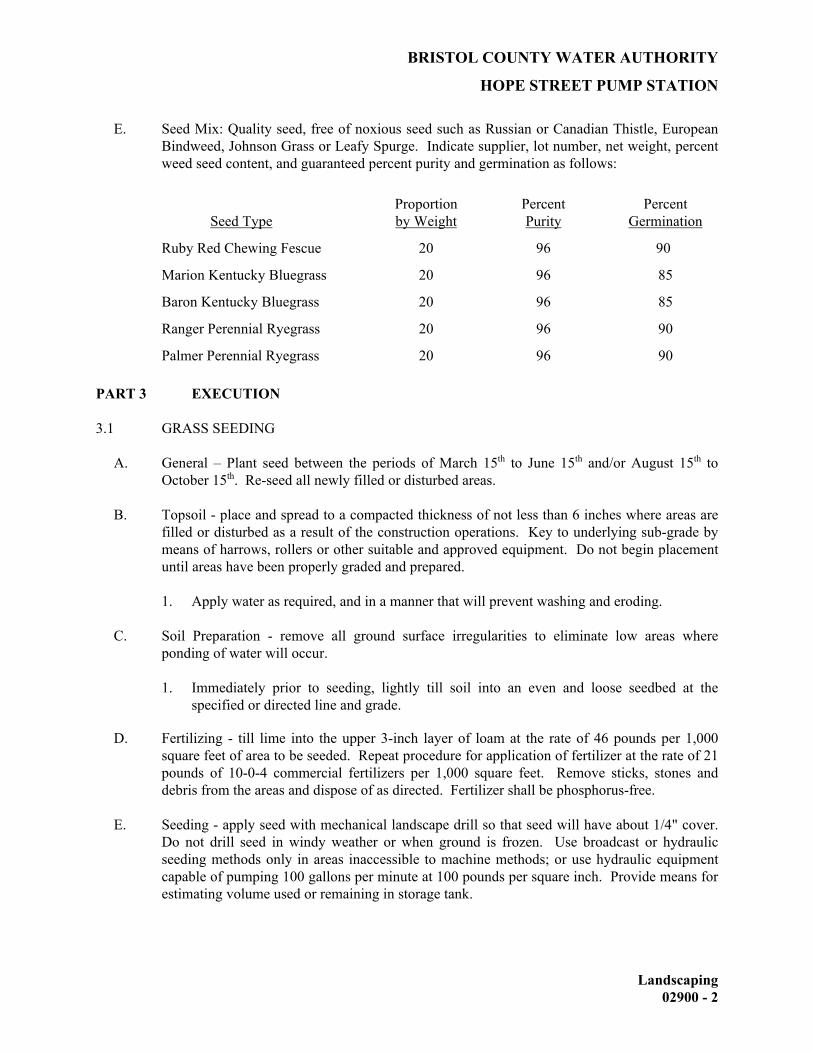
BRISTOL COUNTY WATER AUTHORITY
HOPE STREET PUMP STATION
Landscaping 02900 - 2
E. Seed Mix: Quality seed, free of noxious seed such as Russian or Canadian Thistle, European Bindweed, Johnson Grass or Leafy Spurge. Indicate supplier, lot number, net weight, percent weed seed content, and guaranteed percent purity and germination as follows:
Seed Type Proportion by Weight
Percent Purity
Percent Germination
Ruby Red Chewing Fescue 20 96 90
Marion Kentucky Bluegrass 20 96 85
Baron Kentucky Bluegrass 20 96 85
Ranger Perennial Ryegrass 20 96 90
Palmer Perennial Ryegrass 20 96 90 PART 3 EXECUTION 3.1 GRASS SEEDING A. General – Plant seed between the periods of March 15th to June 15th and/or August 15th to
October 15th. Re-seed all newly filled or disturbed areas. B. Topsoil - place and spread to a compacted thickness of not less than 6 inches where areas are
filled or disturbed as a result of the construction operations. Key to underlying sub-grade by means of harrows, rollers or other suitable and approved equipment. Do not begin placement until areas have been properly graded and prepared.
1. Apply water as required, and in a manner that will prevent washing and eroding. C. Soil Preparation - remove all ground surface irregularities to eliminate low areas where
ponding of water will occur. 1. Immediately prior to seeding, lightly till soil into an even and loose seedbed at the
specified or directed line and grade. D. Fertilizing - till lime into the upper 3-inch layer of loam at the rate of 46 pounds per 1,000
square feet of area to be seeded. Repeat procedure for application of fertilizer at the rate of 21 pounds of 10-0-4 commercial fertilizers per 1,000 square feet. Remove sticks, stones and debris from the areas and dispose of as directed. Fertilizer shall be phosphorus-free.
E. Seeding - apply seed with mechanical landscape drill so that seed will have about 1/4" cover.
Do not drill seed in windy weather or when ground is frozen. Use broadcast or hydraulic seeding methods only in areas inaccessible to machine methods; or use hydraulic equipment capable of pumping 100 gallons per minute at 100 pounds per square inch. Provide means for estimating volume used or remaining in storage tank.
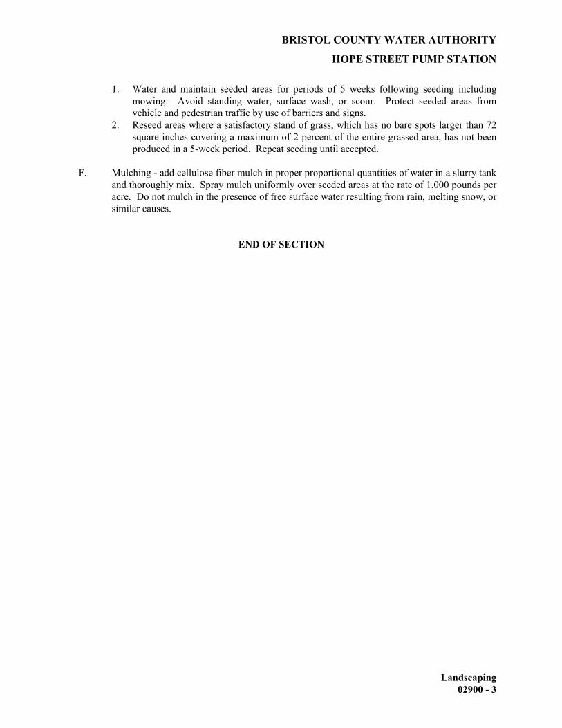
BRISTOL COUNTY WATER AUTHORITY
HOPE STREET PUMP STATION
Landscaping 02900 - 3
1. Water and maintain seeded areas for periods of 5 weeks following seeding including mowing. Avoid standing water, surface wash, or scour. Protect seeded areas from vehicle and pedestrian traffic by use of barriers and signs.
2. Reseed areas where a satisfactory stand of grass, which has no bare spots larger than 72 square inches covering a maximum of 2 percent of the entire grassed area, has not been produced in a 5-week period. Repeat seeding until accepted.
F. Mulching - add cellulose fiber mulch in proper proportional quantities of water in a slurry tank
and thoroughly mix. Spray mulch uniformly over seeded areas at the rate of 1,000 pounds per acre. Do not mulch in the presence of free surface water resulting from rain, melting snow, or similar causes.
END OF SECTION

BRISTOL COUNTY WATER AUTHORITY
HOPE STREET PUMP STATION
DIVISION 3
CONCRETE

BRISTOL COUNTY WATER AUTHORITY
HOPE STREET PUMP STATION
Concrete Formwork 03100 - 1
SECTION 03100 CONCRETE FORMWORK PART 1 GENERAL 1.1 WORK INCLUDED
A. This section specifies requirements for concrete formwork to produce cast-in-place concrete structures as shown on the Drawings and as specified herein. The work shall consist of designing, furnishing, constructing and removing formwork for all cast-in-place concrete structures.
B. Use forms, wherever necessary, to confine the concrete and shape it to the required lines,
and to provide the specified finish. Construct forms with sufficient strength to structurally support the work, and withstand the pressure resulting from placement and vibration of the concrete and maintain forms rigidly in position. Construct forms sufficiently tight to prevent loss of mortar from the concrete.
1.2 REFERENCES
A. American Concrete Institute (ACI):
1. ACI 117: Standard Specification for Tolerances for Concrete Construction and Materials.
2. ACI 301: Standard Specification for Structural Concrete. 3. ACI 347: Guide to Formwork for Concrete. 4. Rhode Island State Building Code
1.3 DESIGN REQUIREMENTS
A. Design formwork to support vertical loads and lateral pressures resulting from placement and vibration of concrete in accordance with the requirements of ACI 301 and ACI 347, and as specified herein.
B. Camber the formwork to compensate for anticipated deflections due to the weight and
pressure of the fresh concrete and due to construction loads.
C. Provide shores and struts with positive means of adjustment capable of taking up formwork settlement during concrete placing operations. Use wedges or jacks, individually or in combination for adjustment.
D. Design forms and falsework to include assumed values of live loads, dead load, weight of
moving equipment operated on formwork, concrete mix, height of drop, vibrator frequency, ambient temperature, lateral stability, and other factors pertinent to the safety of the structure during construction.
E. Provide and design forms to conform with expansion and construction joint locations.

BRISTOL COUNTY WATER AUTHORITY
HOPE STREET PUMP STATION
Concrete Formwork 03100 - 2
1.4 SUBMITTALS
A. Submittals for the following items shall be made in accordance with the requirements as specified in Section 01300, Submittals.
B. Submit the following at least 30 days before the first concrete placement:
1. Manufacturer’s data and installation instructions for proprietary form accessories,
form coatings, pipe sleeves and seals, form ties and manufactured form systems if used.
2. Certification that form coatings comply with the requirements of this Section and utilize a NSF-61 certified form release agent for any concrete that will come in contact with potable water.
1.5 QUALITY CONTROL
A. Provide in accordance with the requirements as specified in Section 01400, Quality Control.
B. Tolerances:
1. Permissible surface irregularities for the various classes of concrete surface finish
as specified in Section 03300, Cast-in-Place Concrete, are defined as “finishes”, and are to be distinguished from tolerances as specified herein. Deviations from the established lines, grades, and dimensions will be permitted to the extent set forth herein.
2. The tolerance limits specified in this Section and the surface finish irregularities permitted in Section 03300, Cast-in-Place Concrete, are not the limits to which forms may be built or by which damaged from sheathing may be used. These limits are provided only for the occasional slight misalignment or irregularity of surface which may occur despite a serious effort to build and maintain the forms accurately and securely with an even surface. These limits will be allowed only for inadvertent or relatively infrequent irregularities of the degree mentioned, but practices and form materials will be prohibited which without doubt will result in the creation of additional irregularities, even though these would be within the limits specified.
3. Where specific tolerances are not stated herein or shown on the Drawings for a structure, portion of a structure, or other feature of the work, permissible deviations will be interpreted conforming to the tolerances stated herein for similar construction. Specific maximum or minimum tolerances as shown on the Drawings in connection with any dimension shall be considered as supplemental to the tolerances specified herein and shall govern. Concrete forms shall be set and maintained within the tolerance limits necessary to ensure that the completed work will be within the tolerances specified. Concrete construction that exceeds the tolerance limits specified or as shown on the Drawings shall be remedied or removed and replaced by the Contractor at no cost to the Owner.
4. Tolerances shall be as specified in ACI 117, Standard Specifications for Tolerances for Concrete and Materials.

BRISTOL COUNTY WATER AUTHORITY
HOPE STREET PUMP STATION
Concrete Formwork 03100 - 3
PART 2 PRODUCTS 2.1 MATERIALS
A. Forms for Exposed Finish Concrete: Construct formwork for exposed concrete surfaces with smooth faced undamaged plywood or metal, metal-framed plywood faced or other acceptable panel-type facing materials approved by Engineer, to provide continuous, straight, smooth as-cast surfaces, and produce a uniform and consistent texture and pattern on the surfaces. Metal patches on forms for these surfaces will not be permitted. Furnish in largest practicable sizes to minimize number of joints and to conform to joint system shown on the Drawings.
1. Use overlaid plywood complying with U.S. Product PS-1 “A-C or B-B High
Density Overlaid Concrete Form”, Class I. 2. Use plywood complying with U.S. Product Standard PS-1 “B-B (Concrete Form)
Plywood”, Class I, Exterior Grade or better, mill-oiled and edge-sealed, with each piece bearing legible inspection trademark.
B. Forms for Unexposed Finish Concrete: Plywood, lumber, metal, or other acceptable
material. Provide lumber dressed on at least 2 edges and one side for tight fit.
C. Tubular Fiber Forms:
1. Provide forms with spirally constructed laminated plies of fiber. 2. Provide forms with wall thickness as recommended by the manufacturer to meet
load requirements of the various uses and sizes. 3. Provide forms with wax coated outside surfaces for moisture resistance. 4. Provide forms with inside surface coated with bond-breaker compound.
D. Form Ties:
1. Form Ties: For concrete structures, which will not be in view or buried below
finish grade, use carbon steel factory-fabricated, removable or stay in place snap-off type form ties, designed to prevent form deflection and to prevent spalling concrete upon removal. Provide units, which will leave no metal closer than 1-1/2” to surface. Provide ties which, when removed, will leave holes not larger than 1” diameter in concrete surface. Patch all holes with non-shrink grout.
2. Form ties and spreaders for walls in areas exposed to view shall be Stainless Steel Cone–Tight Tyscru by Richmond Screw Anchor Co.; Dayton Sure-Grip and Shore Co.; or substitute approved by Program Manager with Plastic cone-tight type cones having a 1” setback and a taper from 1” to 1-1/4”. Tycone holes shall be sealed with plastic set back plugs, color as selected by Engineer from manufacturer’s standard color selection or filled with non-shrink grout. Tyscru ties shall be sized to satisfy loading requirements.
3. In lieu of form ties specified above, fiberglass form tie systems shall be used. Fiberglass form ties shall be standard gray color. The concrete structure shall be finished by grinding the fiberglass form tie flush with the finish surface of the concrete structure.
a. If tapered architectural holes are required, dummy tapered cones having

BRISTOL COUNTY WATER AUTHORITY
HOPE STREET PUMP STATION
Concrete Formwork 03100 - 4
a 1” setback and a taper from 1” to 1-1/4 shall be fastened to the interior of the formwork to achieve the specified pattern on the finish structure.
E. Form Releasing Agents: Provide commercial formulation form-releasing agents that will
not bond with, stain, nor adversely affect concrete surfaces requiring bond or adhesion, nor impede the wetting of surfaces to be cured with water or curing compounds. Volatile organic compound emissions of form coating agent shall not exceed 2.09 pounds per gallon (250 grams per liter). Form release agents utilized on concrete that will come in contact with potable water shall be NSF-61 certified.
F. Chamfer Strips: Provide 1-inch triangular fillets to form all exposed concrete corners.
Material shall be rubber or polyvinyl chloride type, or smooth clear, sealed softwood.
G. Sleeves: Sleeves for wall and floor penetrations shall be pre-engineered Century-Line sleeves as manufactured by Thunderline Corporation or Engineer approved substitute. Sleeves shall be constructed of high impact thermoplastic with waterstop collar, reinforcing ribs and nailer end caps for positioning forms. Sleeve shall be designed to work with modular mechanical seal for through wall penetrations. Size of sleeves shall be selected according to manufacturer’s recommendations for pipe sizes indicated on Drawings.
H. Seals: Sleeve/pipe seals shall be Link-Seal modular mechanical seals as manufactured by
Thunderline Corporation or Engineer approved substitute. The seal shall be modular, mechanical; type, consisting of interlocking synthetic rubber links shaped to continuously fill the annular space between the pipe and the wall opening. The elastomeric element shall be sized and selected per manufacturer’s recommendations and have the following properties as designated by ASTM:
1. For standard service applications: (-40°F to 250°F) EPDM – ASTM D2000 M3
BA 510. 2. For hydrocarbon service applications: (-40°F to 210°F) Nitrile – ASTM D2000
M1BF510. 3. For high temperature or fire seal applications: (-60°F to 400°F) Silicone – ASTM
D2000 M1GE505. PART 3 EXECUTION 3.1 INSPECTION
A. Examine the substrate and conditions under which work of this Section is to be performed, and correct unsatisfactory conditions, which would prevent proper and timely completion of the work. Do not proceed until unsatisfactory conditions have been corrected.

BRISTOL COUNTY WATER AUTHORITY
HOPE STREET PUMP STATION
Concrete Formwork 03100 - 5
3.2 FORM CONSTRUCTION
A. General:
1. Construct forms as designed and in accordance with Contractor’s approved working Drawings conforming to ACI 347, to the exact sizes, shapes, lines, and dimensions shown, and as required to obtain accurate alignment, location, grades, level, and plumb work in finished structures.
2. Provide for openings, offsets, keyways, recesses, moldings, chamfers, blocking, screeds, bulkheads, anchorages, inserts, and other features required. Use selected materials to obtain required finishes.
3. Forms for concrete which accommodate work of other trades, fabricated before the opportunity exists to verify the measurements of adjacent construction, shall be accurately sized and located as dimensioned on the Drawings. In the event that deviation from the Drawing dimensions results in problems in the field, the Contractor shall be responsible for resolution of the conditions as approved by the Engineer, at no cost to the Owner.
B. Fabrication:
1. Fabricate forms for easy removal without hammering or prying against concrete
surfaces. Provide crush plates or wrecking plates where stripping may damage concrete surfaces.
2. Provide temporary openings where interior area of formwork is inaccessible for cleanout, for inspection before concrete placement, and for placement of concrete. Brace temporary closures and set tightly to temporary openings on forms in as many inconspicuous locations as possible, commensurate with design requirements. Form intersecting planes to provide true, clean cut corners.
C. Falsework:
1. Erect falsework and support, brace, and maintain it to safely support vertical,
lateral, and asymmetrical loads applied until complete structure has attained design strength. Construct falsework so that adjustments can be made for take-up and settlement, and access is provided for inspection.
2. Provide wedges, jacks or chamfer strips to facilitate vertical adjustments. Carefully inspect falsework and formwork during and after concrete placement operations to determine abnormal deflection or signs of failure; make necessary adjustments to product work of required dimensions.
D. Forms for Exposed Concrete:
1. Drill forms to suit ties used and to prevent leakage of concrete mortar around tie
holes. Do not splinter forms by driving ties through improperly prepared holes 2. Provide sharp clean corners at intersecting planes, without visible edges or
offsets. Back joints with extra studs or grits to maintain true, square intersections.
3. Use extra studs, walers, and bracing to prevent bowing of forms between studs and to avoid bowed appearance in concrete. Do not use narrow strips of form material, which will produce bow.

BRISTOL COUNTY WATER AUTHORITY
HOPE STREET PUMP STATION
Concrete Formwork 03100 - 6
E. Corner Treatment:
1. Unless shown otherwise, form chamfers with ¾-inch by ¾-inch strips, accurately formed and surfaced to produce uniformly straight lines and tight edge joints on exposed concrete. Extend terminal edges to required limit and miter chamfer strips at changes in direction.
F. Control Joints: Locate as indicated on the Drawings.
G. Provision for Other Trades: Provide openings in concrete formwork to accommodate
work of other trades. Verify size and location of openings, recesses and sleeves with the trade requiring such items. Accurately place and securely support items to be built into forms.
H. Cleaning and Tightening: Thoroughly clean forms and adjacent surfaces to receive
concrete. Remove encrusted mortar and grout, chips, wood, sawdust, dirt, and other debris just before concrete is placed. Retighten forms immediately after concrete placement as required to eliminate mortar leaks.
3.3 FORM COATINGS
A. Coat form contact surfaces with form-releasing agent before reinforcement is placed. Do not allow excess form coating material to accumulate in the forms or to come into contact with surfaces that will be bonded to fresh concrete. Apply in strict compliance with manufacturer’s instructions. Form-releasing agent for form contact surfaces that will come in contact with potable water shall be NSF-61 approved.
B. Remove surplus coating on form surfaces before placing concrete.
3.4 INSTALLATION OF EMBEDDED ITEMS.
A. Set and build into the forms, anchorage devices and other embedded items required for other work that is attached to, or supported by, cast-in-place concrete. Use setting Drawings, diagrams, instructions and directions provided by suppliers of the items to be attached thereto.
B. Set edge forms or bulkheads and intermediate screed strips for slabs, to obtain required
elevation and contours in the finished slab surface. Provide and secure units to support types of screeds required.
3.5 REMOVAL OF FORMS
A. Formwork not supporting concrete, such as sides of walls, columns, and similar parts of the Work, may be removed after cumulatively curing at not less than 50 degrees F for 72 hours after placing concrete, provided concrete is sufficiently hard to not be damaged by form removal operation, and provided that curing and protection operations are maintained.
B. Formwork supporting weight of concrete, such as elevated beams, joists, slabs and other
structural elements may not be removed until concrete has attained 70% of its design

BRISTOL COUNTY WATER AUTHORITY
HOPE STREET PUMP STATION
Concrete Formwork 03100 - 7
minimum 28-day compressive strength and has cumulatively cured for no less than 7 days. Concrete shall have sufficient strength to safely support its own weight and construction live loads and lateral pressures. Determine potential compressive strength of in-place concrete testing field-cured specimens representative of the concrete location or members, as specified in Section 03300, Cast-in-Place Concrete.
C. Form facing material may be removed one day after placement, only if shores and other
vertical supports have been arranged to permit removal of form facing material without loosening or disturbing shores and supports.
D. Form ties: The concrete structure shall be finished by grinding the fiberglass form ties
flush with the finish surface of the concrete structure. 3.6 REUSE OF FORMS
A. Clean and repair surfaces of forms to be reused in the work. Split, frayed, delaminated or otherwise damaged form facing material will not be acceptable. When forms are reused for successive concrete placement, thoroughly clean surfaces, remove fins and laitance, and tighten forms to close all joints. Align and secure joints to avoid offsets. Apply new form releasing agent to all form areas that will be in contact with concrete.
B. Do not reuse forms if there is any evidence of surface wear and tear, splits, fraying,
delamination or other damage which would impair the quality of the concrete surface or prevent obtaining the specified concrete finish.
END OF SECTION

BRISTOL COUNTY WATER AUTHORITY
HOPE STREET PUMP STATION
Concrete Reinforcement 03200 - 1
SECTION 03200 CONCRETE REINFORCEMENT PART 1 GENERAL 1.1 WORK INCLUDED
A. This Section specifies all work necessary to provide all concrete reinforcement such as reinforcing steel, welded wire fabric, mechanical couplers and concrete inserts as shown on the Drawings and as specified herein.
1.2 RELATED WORK SPECIFIED ELSEWHERE
Section 03100 – Concrete Formwork Section 03300 – Cast-in-Place Concrete 1.3 REFERENCES
A. American Concrete Institute (ACI)
1. ACI 315: Details and Detailing of Concrete Reinforcement 2. ACI 315R: Manual of Engineering and Placing Drawings for Reinforced
Concrete Structures
B. American Society for Testing and Materials (ASTM):
1. A185: Specification for Steel Welded Wire, Fabric, Plain, for Concrete Reinforcement
2. A 615: Specification for Deformed and Plain Billet-Steel Bars for Concrete Reinforcement
3. A 706/A 706M: Specification for Low-Alloy Steel Deformed Bars for Concrete Reinforcement
C. American Welding Society (AWS):
1. AWS D1.4: American Welding Society, Structural Welding Code, Reinforcing Steel.
D. Rhode Island State Building Code
1.4 QUALITY CONTROL
A. Do not fabricate reinforcement until shop and placement drawings have been approved by the Engineer.
B. Tolerances:
1. Tolerances shall be as specified in ACI 315R.
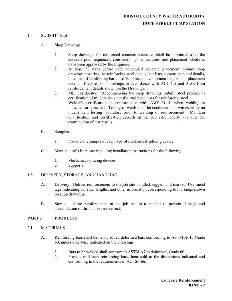
BRISTOL COUNTY WATER AUTHORITY
HOPE STREET PUMP STATION
Concrete Reinforcement 03200 - 2
1.5 SUBMITTALS
A. Shop Drawings:
1. Shop drawings for reinforced concrete structures shall be submitted after the concrete pour sequences, construction joint locations, and placement schedules have been approved by the Engineer.
2. At least 30 days before each scheduled concrete placement, submit shop drawings covering the reinforcing steel details, bar lists, support bars and details, locations of reinforcing bar cut-offs, splices, development lengths and placement details. Prepare shop drawings in accordance with ACI 315 and 315R from reinforcement details shown on the Drawings.
3. Mill Certificates: Accompanying the shop drawings, submit steel producer’s certification of mill analysis, tensile, and bend tests for reinforcing steel.
4. Welder’s certification in conformance with AWS D1.4, when welding is indicated or specified. Testing of welds shall be conducted and witnessed by an independent testing laboratory prior to welding of reinforcement. Maintain qualification and certification records at the job site, readily available for examination of test results.
B. Samples:
1. Provide one sample of each type of mechanical splicing device.
C. Manufacture’s literature including installation instructions for the following:
1. Mechanical splicing devices 2. Supports
1.6 DELIVERY, STORAGE, AND HANDLING
A. Delivery: Deliver reinforcement to the job site bundled, tagged, and marked. Use metal tags indicating bar size, lengths, and other information corresponding to markings shown on shop drawings.
B. Storage: Store reinforcement at the job site in a manner to prevent damage and
accumulation of dirt and excessive rust. PART 2 PRODUCTS 2.1 MATERIALS
A. Reinforcing bars shall be newly rolled deformed bars conforming to ASTM A615 Grade 60, unless otherwise indicated on the Drawings.
1. Bars to be welded shall conform to ASTM A706 deformed, Grade 60. 2. Provide mill bent reinforcing bars, bent cold to the dimensions indicated and
conforming to the requirements of ACI SP-66.
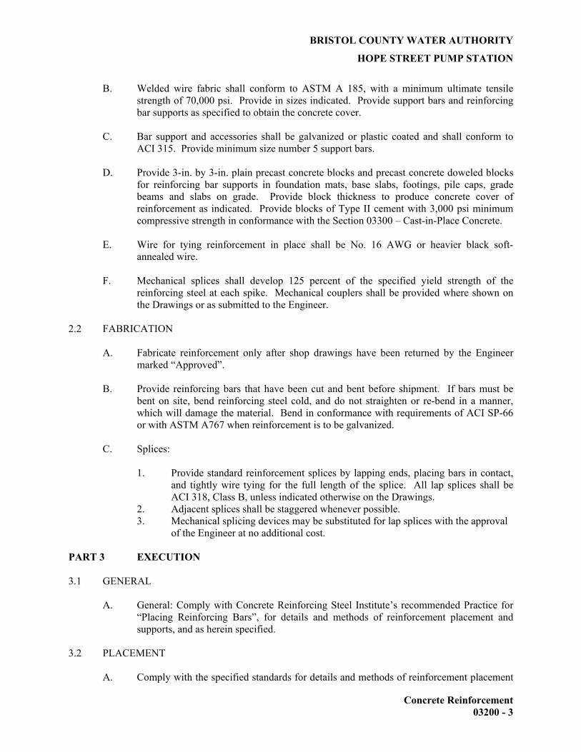
BRISTOL COUNTY WATER AUTHORITY
HOPE STREET PUMP STATION
Concrete Reinforcement 03200 - 3
B. Welded wire fabric shall conform to ASTM A 185, with a minimum ultimate tensile strength of 70,000 psi. Provide in sizes indicated. Provide support bars and reinforcing bar supports as specified to obtain the concrete cover.
C. Bar support and accessories shall be galvanized or plastic coated and shall conform to
ACI 315. Provide minimum size number 5 support bars.
D. Provide 3-in. by 3-in. plain precast concrete blocks and precast concrete doweled blocks for reinforcing bar supports in foundation mats, base slabs, footings, pile caps, grade beams and slabs on grade. Provide block thickness to produce concrete cover of reinforcement as indicated. Provide blocks of Type II cement with 3,000 psi minimum compressive strength in conformance with the Section 03300 – Cast-in-Place Concrete.
E. Wire for tying reinforcement in place shall be No. 16 AWG or heavier black soft-
annealed wire.
F. Mechanical splices shall develop 125 percent of the specified yield strength of the reinforcing steel at each spike. Mechanical couplers shall be provided where shown on the Drawings or as submitted to the Engineer.
2.2 FABRICATION
A. Fabricate reinforcement only after shop drawings have been returned by the Engineer marked “Approved”.
B. Provide reinforcing bars that have been cut and bent before shipment. If bars must be
bent on site, bend reinforcing steel cold, and do not straighten or re-bend in a manner, which will damage the material. Bend in conformance with requirements of ACI SP-66 or with ASTM A767 when reinforcement is to be galvanized.
C. Splices:
1. Provide standard reinforcement splices by lapping ends, placing bars in contact,
and tightly wire tying for the full length of the splice. All lap splices shall be ACI 318, Class B, unless indicated otherwise on the Drawings.
2. Adjacent splices shall be staggered whenever possible. 3. Mechanical splicing devices may be substituted for lap splices with the approval
of the Engineer at no additional cost. PART 3 EXECUTION 3.1 GENERAL
A. General: Comply with Concrete Reinforcing Steel Institute’s recommended Practice for “Placing Reinforcing Bars”, for details and methods of reinforcement placement and supports, and as herein specified.
3.2 PLACEMENT
A. Comply with the specified standards for details and methods of reinforcement placement

BRISTOL COUNTY WATER AUTHORITY
HOPE STREET PUMP STATION
Concrete Reinforcement 03200 - 4
and supports, and as herein specified.
B. Clean reinforcement to remove loose rust and mill scale, earth, and other materials that would reduce or destroy bond with concrete.
C. Position, support, and secure reinforcement against displacement by formwork,
construction, or concrete placement operations. Locate and support reinforcing by metal chairs, runners, bolsters, spacers, and hangers, as required.
D. Place reinforcement to obtain the specified coverage for concrete protection. Arrange,
space, and securely tie bars and bar supports together with wire, to hold reinforcement accurately in position during concrete placement operation. Set wire ties so that twisted ends are directed away from exposed concrete surfaces.
E. Install welded wire fabric in lengths as long as practicable. Lap adjoining pieces at least
one full mesh.
F. Provide supports of sufficient numbers and strengths to carry reinforcement. Do not place reinforcing bars more than 2 inches beyond the last leg of any continuous bar support. Do not use supports as bases for runways for conveying equipment and similar construction loads.
G. Bars may be moved as necessary to avoid interference with other reinforcing steel,
conduits or embedded items. Bars moved more than three inches are subject to approval of Engineer. Place required number of bars.
H. Position dowels accurately. Rigidly support, securely tie. Align dowels normal to
concrete surface before concrete placement. Setting dowels into wet concrete is prohibited.
I. Provide and place safety caps on all exposed ends of vertical reinforcement.
J. Tie a minimum of 25 percent of all intersecting bars in foundation mats, base slabs,
footings, pile caps, slabs on grade and elevated slabs.
K. Do not splice reinforcement steel in foundation mats, base slabs, beams, girders, slabs and walls at points of maximum stress unless otherwise indicated.
L. Lab splice welded wire fabric reinforcement at least two full meshes. Stagger splices to
avoid continuous laps in either direction and wire tightly together. Straighten rolled welded wire fabric reinforcement into flat sheets before use.
M. Provide continuous reinforcement through construction joints.
END OF SECTION

BRISTOL COUNTY WATER AUTHORITY
HOPE STREET PUMP STATION
Cast-in-Place Concrete 03300 - 1
SECTION 03300 CAST-IN-PLACE CONCRETE PART 1 GENERAL 1.1 WORK INCLUDED
A. This Section specifies requirements for furnishing, placement, finishing, curing and protecting of all concrete, plain and reinforced as shown on the Drawings and as specified herein. Review and approval of the Contractor’s working drawings by the Engineer does not relieve the Contractor of the responsibility for the adequacy of work.
1.2 REFERENCES
A. General: Where the language in any of the documents referred to herein is in the form of a recommendation or suggestion, such recommendations or suggestions shall be deemed to be mandatory for these Specifications.
B. American Concrete Institute (ACI):
1. ACI 117: Standard Tolerances for Concrete Construction and Materials 2. ACI 301: Specifications for Structural Concrete 3. ACI 302: Guide for Concrete Floor and Slab Construction 4. ACI 304R: Guide for Measuring, Mixing, Transporting and Placing Concrete. 5. ACI 305R: Hot Weather Concreting 6. ACI 306: Cold Weather Concreting 7. ACI 308: Standard Practice for Curing Concrete 8. ACI 309R: Guide for Consolidation of Concrete 9. ACI 318: Building Code Requirements for Structural Concrete
C. American Society for Testing and Materials (ASTM):
1. C31: Making and Curing Concrete Compression and Flexural Strength Test-
Specimens in the Field. 2. C33: Specification for Concrete Aggregates 3. C39: Test Method for Compressive Strength of Cylindrical Concrete Specimens 4. C94: Specifications for Ready Mixed Concrete 5. C136: Sieve Analysis of Fine and Coarse Aggregate 6. C138: Unit Weight, Yield, and Air Content of Concrete 7. C143: Test for Slump of Portland Cement Concrete 8. C150: Specification for Portland Cement 9. C171: Sheet Materials for Curing Concrete 10. C172: Sampling Fresh Concrete 11. C231: Test for Air Content of Freshly Mixed Concrete by the Pressure Method 12. C260: Specification for Air-Entraining Admixtures for Concrete
13. C309: Specification for Liquid Membrane Forming Compounds for Curing
Concrete 14. C494: Specification for Chemical Admixtures for Concrete 15. C827: “Test Method for Change in Height at Early Ages of Cylindrical
Specimens from Cementitious Mixtures

BRISTOL COUNTY WATER AUTHORITY
HOPE STREET PUMP STATION
Cast-in-Place Concrete 03300 - 2
16. C989: Specification for Ground Iron Blast-Furnace Slag for Use in Concrete and Mortars
17. C1064: Test Method for Temperature of Freshly Mixed Portland-Cement Concrete
18. C1107: Specification for Packaged Dry, hydraulic Cement Grout (Non-Shrink) 19. C1240: Standard Specification for Silica Fume for Use in Hydraulic-Cement
Concrete 20. D1751: Specification for Preformed Expansion Joint Fillers for Concrete Paving
and Structural Construction (Nonextruding and Resilient Bituminous Types). 21. E154: Test Methods for Water Vapor Retarders Used in Contact with Earth under
Concrete Slabs, on Walls, or as Ground Cover 1.3 QUALITY CONTROL
A. Concrete Testing Service: The Contractor shall employ and pay an independent testing laboratory to perform material evaluation tests and to design concrete mixes and provide copies of recently made material tests and mix designs.
B. Materials and installed work may require testing and retesting at any time during progress
of work. Allow free access to material stockpiles and facilities. All tests, including retesting of rejected materials and installed work, shall be done at Contractor’s expense.
C. Workmanship: The Contractor is responsible for correction of corrected work that does
not conform to the specified requirements, including strength, tolerances and finishes. Correct deficient concrete as directed at no additional cost to the Owner.
1.4 DESIGN REQUIREMENTS
A. Codes: Building concrete shall be in conformance with the requirements of ACI 318, and the Rhode Island State Building Code.
B. Air entrain all concrete, except interior slabs-on-grade. C. Any concrete that will come in contact with potable water shall utilize NSF 61 certified
concrete admixtures. 1.5 SUBMITTALS
A. Product Data: Submit design mix as applicable. Submit manufacturer’s product data with application and installation instructions for proprietary materials and items, including reinforcement and forming accessories, admixtures, patching compounds, waterstops, joint systems, curing compound, and others as requested by the Engineer.
B. Shop Drawings: Submit working drawings for all work under this Section to the
Engineer for approval. Show location of joints, concrete pouring sequence, schedule dates, rate of placement and methods.
C. All concrete mix designs shall conform to ACI-318, Chapter 5 and as specified. All
concrete mix designs and concrete material tests shall be signed and sealed by a Professional Engineer in the State of Rhode Island.

BRISTOL COUNTY WATER AUTHORITY
HOPE STREET PUMP STATION
Cast-in-Place Concrete 03300 - 3
D. Samples: Submit samples of materials as specified, including names, sources and descriptions.
E. Laboratory Test Reports: Submit laboratory test reports for concrete, concrete materials,
and mix design tests.
F. Material Certificates: Provide materials certificates in lieu of materials laboratory test reports when permitted. Material certificates shall be signed by manufacturer and Contractor, certifying that each material item complies with, or exceeds, specified requirements.
G. Submit prior to start of work written reports of each proposed mix for each class of
concrete. Do not begin concrete production until mixes have been approved by the Engineer.
H. Batch Ticket Information: Provide concrete delivery tickets showing job name and
location, date and time of delivery, quantity of concrete, quality and type of concrete, admixtures, amount of water added, and all other relevant information as described in ASTM C-94. Submit original batch tickets and 2 copies at the end of each week.
1.6 DELIVERY, STORAGE, AND HANDLING
A. Order concrete from batching plant so that trucks arrive at discharge locations when concrete is required. Avoid excessive mixing of concrete or delays in placing successive layers of concrete in forms.
B. Deliver concrete to discharge locations in watertight agitator or mixer trucks without
altering the water-cement ratio, slump, air entrainment, temperature and homogeneity.
C. Concrete not conforming to specification, unsuitable for placement, exceeding the time or temperature limitations or not having a complete delivery batch ticket will be rejected.
1.7 JOB SITE CONDITIONS
A. Weather: Protect concrete from damage and reduced strength or performance due to weather extremes during mixing, placing and curing.
B. Cold Weather: Unless special precautions are taken to protect concrete, do not work
when temperatures are below 40°F or when temperatures are expected to fall below 40°F within 72 hours after placing concrete.
1. Comply with ACI 306 in cold weather. 2. Maintain concrete temperature of at least 60°F. Reinforcement, forms and
ground in contact with concrete shall be free of frost. 3. Keep concrete and formwork at least 50°F for at least 96 hours after placing
concrete. 4. The use of calcium chloride in any form is not permitted. Non-chloride
accelerator shall be used when ambient temperature is below 50°F. 5. Admixture manufacturer shall provide technical assistance at no additional cost.

BRISTOL COUNTY WATER AUTHORITY
HOPE STREET PUMP STATION
Cast-in-Place Concrete 03300 - 4
A manufacturer’s representative shall be available for consultation by phone or on site upon 72-hour notice.
C. Hot Weather: Concrete, when deposited, shall be less than 85°F. Cool the mix in a
manner acceptable to the Engineer if the concrete temperature is higher.
1. Comply with ACI 305 in hot weather. 2. Retarder shall be used when ambient temperature exceeds 80°F.
PART 2 PRODUCTS 2.1 CONCRETE MATERIALS
A. Portland Cement: ASTM C 150, Type II for all work unless otherwise specified. Use one brand of cement throughout project.
B. Normal Weight Aggregates: ASTM C 33, and as herein specified. Use ¾” maximum
size for all concrete, unless otherwise directed or specified. Provide aggregates from a single source for exposed concrete.
C. Water: Clean, potable and free from foreign materials in amounts harmful to concrete
and embedded steel. Provide water, which meets ACI/ASTM requirements for concrete mix water.
D. Air-Entraining Admixture: ASTM C 260 and NSF 61 approved; certified by
manufacturer to be compatible with other required admixtures.
1. Products: Subject to compliance with requirements, products that may be incorporated in the work include the following:
a. “Air-Mix”; Euclid Chemical Co. b. “Sika AeA-14”; Sika Corp. c. “MasterAir VR 10 or MasterAir AE 90”; Master Builders d. “Darex AEA” or “Daravair”; W.R. Grace e. Or equivalent.
E. Water Reducing Admixture: ASTM C 494, Type A, and containing not more than 0.1%
chloride ions. Follow manufacturer’s recommendations for amount of admixture to be added to the concrete. Admixture shall be NSF 61 approved and compatible with air-entraining admixtures.
1. “WRDA Hycol”; W. R. Grace. 2. “Eucon WR-75”; Euclid Chemical Co. 3. “Master Pozzolith”’ Master Builders 4. “Sikament 686”; Sika Chemical Corp. 5. Or equivalent.
F. High-Range Water Reducing Admixture (SuperPlasticizer): ASTM C 494, Type F or
Type G and containing not more than 0.1% chloride ions. Admixture shall be NSF 61

BRISTOL COUNTY WATER AUTHORITY
HOPE STREET PUMP STATION
Cast-in-Place Concrete 03300 - 5
approved. Follow manufacturer’s recommendations.
1. Products: Subject to compliance with requirements, products which may be incorporated in the work include the following: a. “WRDA 10” or “Daracem”; W. R. Grace. b. “PSP”; Protex Industries Inc. c. “Super P”; Anit-Hydro. d. “Sikament”; Sika Chemical Corp. e. “Master Rheobuild 1000”; Master Builders. f. Or equivalent.
G. Water Reducing, Non-Chloride Accelerator Admixture: ASTM C 494, Type E or C, and
containing not more than 0.1% chloride ions. Admixture shall be NSF 61 approved.
1. Products: Subject to compliance with requirements, provide one of the following:
a. “Accelguard 80”; Euclid Chemical Co. b. “MasterSet FP 20”; Master Builders, Inc. c. “PolarSet”; Grace Construction Products. d. Or equivalent.
H. Water Reducing, Retarding Admixture: ASTM C 494 Type D, and containing not more
than 0.1% chloride ions. Admixture shall be NSF 61 approved.
1. Products: Subject to compliance with requirements, products that may be incorporated in the work include the following:
a. “MasterPozzolith-80”; Master Builders. b. “Eucon Retarder 75”; Euclid Chemical Co. c. “Daratard 17”; W. R. Grace. d. “Plastiment”; Sika Chemical Co. e. Or equivalent.
I. Prohibited Admixtures: Calcium chloride thyocyanates or admixtures containing more
than 0.1% chloride ions are not permitted. 2.2 RELATED MATERIALS
A. Absorptive Cover: Burlap cloth made from jute or kenaf, weighing approximately 9 oz. per sq. yd., complying with AASHTO M 182, Class 2.
B. Moisture-Retaining Cover: One of the following, complying with ASTM C 171.
1. Waterproof paper. 2. Polyethylene film. 3. Polyethylene-coated burlap.

BRISTOL COUNTY WATER AUTHORITY
HOPE STREET PUMP STATION
Cast-in-Place Concrete 03300 - 6
C. Liquid Membrane-Forming Curing Compound: Liquid type membrane-forming curing compound complying with ASTM C 309, Type I, Class A. Moisture loss not more than 0.055 gr./sq. cm. when applied at 200 sq. ft./gal.
1. Products: Subject to compliance with requirements, products which may be
incorporated in the work include, but are not limited to, the following:
a. “MasterKure”; Master Builders. b. “A-H 3 Way Sealer”; Anti-Hydro Waterproofing Co. c. “Kurez DR VOX”; Euclid Chemical Co. d. “Clear Seal”: A.C. Horn, Inc. e. “Sealco 309”; Gifford-Hill/American Admixtures. f. “Cure & Seal LV 25% J20UV”; Dayton Superior.
D. Underlayment Compound: Free flowing, self-leveling, pumpable cementitious base
compound.
1. Products: Subject to compliance with requirements, products which may be incorporated in the work include, but are not limited to, the following:
a. “Ardex K-15”; Ardex Engineered Cements. b. “Silflo 230”; Silpro Masonry Systems. c. “Ultraplan”; Mapei.
E. Bonding Compound: Polyvinyl acetate or acrylic base.
1. Products: Subject to compliance with requirements, products that may be
incorporated in the work include, but are not limited to, the following:
a. Acrylic or Styrene Butadiene:
i. “J-40 Bonding Agent”; Dayton Superior Corp. ii. “Everbond”; L & M Construction Chemicals. iii. “Hornweld”; A. C. Horn, Inc. iv. “Daraweld C”; W. R. Grace.
F. Adjustable inserts: Adjustable inserts shall be hot-dip galvanized in conformance with
ASTM A123 and A153. Adjustable insets shall be:
1. Ductile iron wedges inserts, Type F-7 manufactured by Dayton Sure-Grip & Shore Co.
2. Malleable iron peerless wedge inserts, insert as manufactured by Richmond Screw, Anchor Co., Inc.
3. Malleable iron wedge inserts, Type HW as manufactured by Hohmann & Barnard Inc.
G. Vapor barrier: Vapor barrier shall be Stego Wrap Vapor Barrier (15 mil) or equivalent, in
accordance with ASTM E 1745. Use caution to avoid perforations in the vapor barrier material. Install barrier in accordance with ASTM E 1643 and ASTM F 710 guidelines.
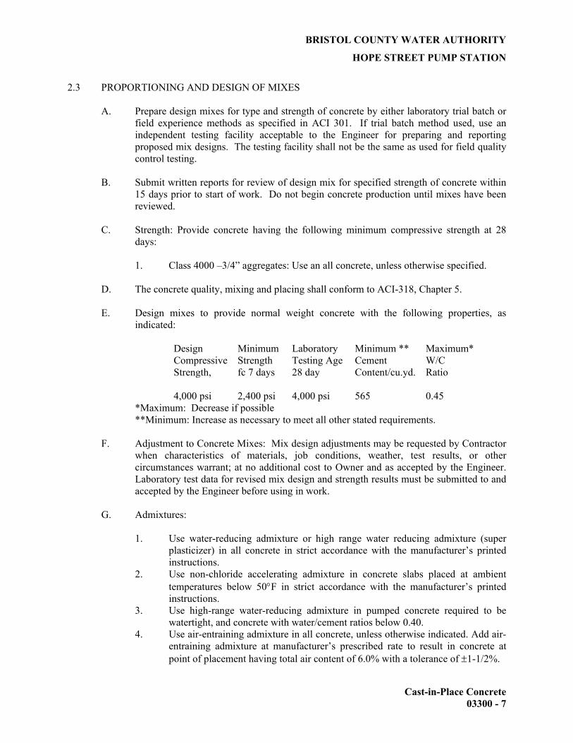
BRISTOL COUNTY WATER AUTHORITY
HOPE STREET PUMP STATION
Cast-in-Place Concrete 03300 - 7
2.3 PROPORTIONING AND DESIGN OF MIXES
A. Prepare design mixes for type and strength of concrete by either laboratory trial batch or field experience methods as specified in ACI 301. If trial batch method used, use an independent testing facility acceptable to the Engineer for preparing and reporting proposed mix designs. The testing facility shall not be the same as used for field quality control testing.
B. Submit written reports for review of design mix for specified strength of concrete within
15 days prior to start of work. Do not begin concrete production until mixes have been reviewed.
C. Strength: Provide concrete having the following minimum compressive strength at 28
days:
1. Class 4000 –3/4” aggregates: Use an all concrete, unless otherwise specified.
D. The concrete quality, mixing and placing shall conform to ACI-318, Chapter 5.
E. Design mixes to provide normal weight concrete with the following properties, as indicated:
Design Compressive Strength,
Minimum Strength fc 7 days
Laboratory Testing Age 28 day
Minimum ** Cement Content/cu.yd.
Maximum* W/C Ratio
4,000 psi 2,400 psi 4,000 psi 565 0.45
*Maximum: Decrease if possible **Minimum: Increase as necessary to meet all other stated requirements.
F. Adjustment to Concrete Mixes: Mix design adjustments may be requested by Contractor when characteristics of materials, job conditions, weather, test results, or other circumstances warrant; at no additional cost to Owner and as accepted by the Engineer. Laboratory test data for revised mix design and strength results must be submitted to and accepted by the Engineer before using in work.
G. Admixtures:
1. Use water-reducing admixture or high range water reducing admixture (super
plasticizer) in all concrete in strict accordance with the manufacturer’s printed instructions.
2. Use non-chloride accelerating admixture in concrete slabs placed at ambient temperatures below 50°F in strict accordance with the manufacturer’s printed instructions.
3. Use high-range water-reducing admixture in pumped concrete required to be watertight, and concrete with water/cement ratios below 0.40.
4. Use air-entraining admixture in all concrete, unless otherwise indicated. Add air-entraining admixture at manufacturer’s prescribed rate to result in concrete at point of placement having total air content of 6.0% with a tolerance of ±1-1/2%.
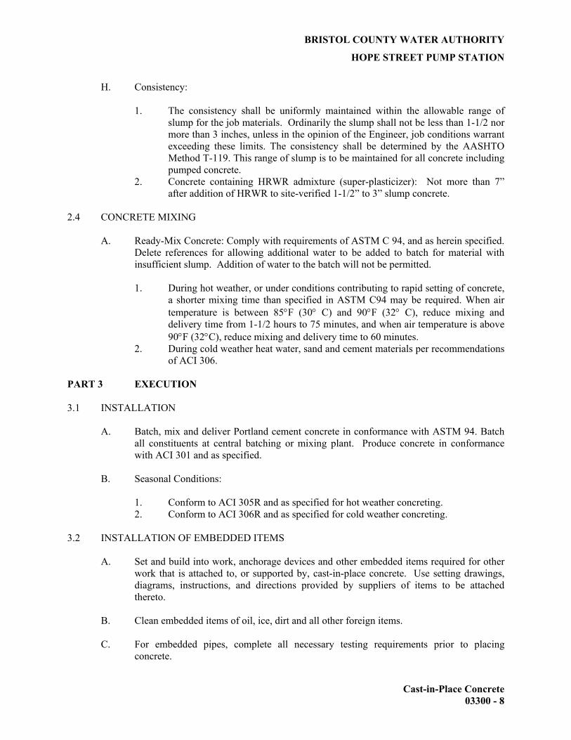
BRISTOL COUNTY WATER AUTHORITY
HOPE STREET PUMP STATION
Cast-in-Place Concrete 03300 - 8
H. Consistency:
1. The consistency shall be uniformly maintained within the allowable range of slump for the job materials. Ordinarily the slump shall not be less than 1-1/2 nor more than 3 inches, unless in the opinion of the Engineer, job conditions warrant exceeding these limits. The consistency shall be determined by the AASHTO Method T-119. This range of slump is to be maintained for all concrete including pumped concrete.
2. Concrete containing HRWR admixture (super-plasticizer): Not more than 7” after addition of HRWR to site-verified 1-1/2” to 3” slump concrete.
2.4 CONCRETE MIXING
A. Ready-Mix Concrete: Comply with requirements of ASTM C 94, and as herein specified. Delete references for allowing additional water to be added to batch for material with insufficient slump. Addition of water to the batch will not be permitted.
1. During hot weather, or under conditions contributing to rapid setting of concrete,
a shorter mixing time than specified in ASTM C94 may be required. When air temperature is between 85°F (30° C) and 90°F (32° C), reduce mixing and delivery time from 1-1/2 hours to 75 minutes, and when air temperature is above 90°F (32°C), reduce mixing and delivery time to 60 minutes.
2. During cold weather heat water, sand and cement materials per recommendations of ACI 306.
PART 3 EXECUTION 3.1 INSTALLATION
A. Batch, mix and deliver Portland cement concrete in conformance with ASTM 94. Batch all constituents at central batching or mixing plant. Produce concrete in conformance with ACI 301 and as specified.
B. Seasonal Conditions:
1. Conform to ACI 305R and as specified for hot weather concreting. 2. Conform to ACI 306R and as specified for cold weather concreting.
3.2 INSTALLATION OF EMBEDDED ITEMS
A. Set and build into work, anchorage devices and other embedded items required for other work that is attached to, or supported by, cast-in-place concrete. Use setting drawings, diagrams, instructions, and directions provided by suppliers of items to be attached thereto.
B. Clean embedded items of oil, ice, dirt and all other foreign items.
C. For embedded pipes, complete all necessary testing requirements prior to placing
concrete.

BRISTOL COUNTY WATER AUTHORITY
HOPE STREET PUMP STATION
Cast-in-Place Concrete 03300 - 9
3.3 PLACING CONCRETE
A. General:
1. Concrete formwork shall satisfy the requirements of Section 03100, Concrete Formwork. Do not place concrete until the depth, character and adequacy of forms, falsework, embedments, and the placing of the steel reinforcement have been approved by the Engineer. The method and manner of placing the concrete shall be such as to avoid segregation of aggregate and displacement of the reinforcement. Troughs, pipes and chutes may be used as aids in placing concrete when necessary. Dropping the concrete a distance of more than five feet, or depositing a large quantity at one point, will not be permitted. Concrete shall be placed upon clean, damp surfaces, free from running water, or upon properly consolidated soil.
2. Retempering of concrete by adding water or any other material shall not be permitted.
3. Concrete placement, finishing and curing, and all other pertinent construction practices shall be in accordance with ACI 117 and ACI 301. In addition to the requirements of ACI 117 and ACI 301, the following shall apply:
a. Concrete shall be placed so that a uniform appearance of surfaces will be
obtained. b. Concrete shall be placed and consolidated free of rock pockets,
honeycombs, and voids. c. Concrete shall be deposited as nearly as practicable in its final position,
to avoid segregation due to rehandling or flowing, and shall not be subjected to any procedure that will cause segregation.
d. Concrete shall be placed and consolidated in walls in approximately 18-inch layers, proceeding at a uniform rate or per the form designer’s recommendation.
B. Consolidating:
1. Consolidate concrete with suitable mechanical vibrators operating within
concrete. When necessary, vibrating shall be supplemented by hand spading with suitable tools to assure proper and adequate consolidation. Vibrators shall be manipulated so as to work the concrete thoroughly around the reinforcement and embedded fixtures and into corners and angles of the forms. The vibration at any joint shall be of sufficient duration to accomplish consolidation but shall not be prolonged to the point where segregation occurs.
2. Employ as many vibrators and tampers as necessary to secure the desired results. For every two vibrators required for the job, an additional standby vibrator shall be kept on the site. Do not place subsequent layers of concrete until the previous layer has been consolidated as specified. Internal vibrators shall have a minimum frequency of 8000 vibrations per minute when immersed in concrete and shall have sufficient amplitude to effectively consolidate the concrete.
3. Prevent the following practices:
a. Pushing of concrete with vibrator. b. External vibration of forms.

BRISTOL COUNTY WATER AUTHORITY
HOPE STREET PUMP STATION
Cast-in-Place Concrete 03300 - 10
c. Allowing vibrator to vibrate against reinforcing steel where steel projects into green concrete.
d. Allowing vibrator to vibrate against the contact faces of forms.
C. Cold Weather: Do not place concrete when the ambient temperature is below 40°F, unless specifically authorized by the Engineer. Conform to the requirements of ACI 306R during cold weather.
D. Hot Weather: Do not place concrete with a mix temperature exceeding 90°F, unless
specifically authorized by the Engineer. Conform to the requirements of ACI 305R during hot weather.
E. Construction Joints:
1. When the placing of concrete is suspended, necessary provisions shall be made
for joining future work before the placed concrete takes its initial set. For the proper bonding of old and new concrete, such provisions shall be made for grooves, steps, keys, dovetails, reinforcing bars or other devices as may be prescribed. Before depositing new concrete against concrete, which has hardened, the surface of the hardened concrete shall be cleaned by a heavy steel broom, roughened slightly, wetted, and covered with a neat coating of cement paste or grout. Install joint sealant where shown on the Drawings, in accordance with manufacturer’s instructions.
2. Joints shall be perpendicular to the main reinforcement.
F. Expansion and Control Joints: Expansion and control joints shall be constructed in the locations and to the dimensions and details shown on the Drawings.
G. Defective Work:
1. All defective work disclosed after the forms have been removed shall be
immediately removed and replaced. If dimensions are deficient, or if the surface of the concrete is bulged, uneven, or shows honeycomb, which in the opinion of the Engineer cannot be repaired satisfactorily, the entire section shall be removed and replaced at no cost to the Owner.
2. Other work considered to be defective includes, but is not limited to, the following:
a. Concrete in which defective or inadequate steel reinforcement has been
placed. b. Concrete incorrectly formed, or not conforming to details and
dimensions on the Drawings or with the intent of these documents, or the concrete surfaces of which are out of plumb or level beyond specified tolerances.
c. Concrete below specified strength. d. Concrete containing wood, cloth, or other foreign matter, rock pockets,
voids, honeycombs, cracks or cold joints not scheduled or indicated on the Drawings.

BRISTOL COUNTY WATER AUTHORITY
HOPE STREET PUMP STATION
Cast-in-Place Concrete 03300 - 11
3.4 CONCRETE FINISHING
A. Exposed concrete surfaces shall be true, smooth, and free from open or rough spaces, depressions, or projections. The concrete in horizontal plane surfaces shall be brought flush with the finished top surface at the proper elevation and shall be struck off with a straightedge and floated. Mortar finishing will not be permitted, nor shall dry cement or sand-cement mortar be spread over the concrete during the finishing of horizontal plane surfaces.
B. Following placement of concrete for slabs, tamp to force coarse aggregate away from
surface, bull float, and steel trowel.
C. The following requirements shall govern concrete finishes so indicated on the Drawings.
1. Float Finish: Force coarse aggregate away from surface; float to a smooth and even surface.
2. Trowel Finish:
a. After floating, begin the first trowel finish operation using a power-driven trowel; begin final troweling when the surface produces a ringing sound as the trowel is moved over the surface.
b. Consolidate the concrete surface by the final hand troweling operation, free from trowel marks, uniform in texture and appearance, and with a surface plane tolerance not exceeding 1/8” in 10’-0” when tested with a 10’-0” straight–edge
3. Broom Finish:
a. Apply nonslip broom finish to exterior concrete as specified,
immediately after trowel finishing; roughen the concrete surface by brooming in the direction perpendicular to the main traffic route.
i. Use a fiber bristle broom. ii. Frequently clean broom to avoid deep brooming.
4. As-Cast Finish:
a. Rough form finish; tie holes and defects shall be patched.
i. Fins exceeding ¼ inch in height shall be chipped off or rubbed
off. ii. Otherwise, surfaces shall be left with the texture imparted by the
forms.
b. Smooth form finish: the form facing material shall produce a smooth, hard, uniform texture on concrete.
i. The arrangement of the facing material shall be orderly and
symmetrical, and the number of seams kept to the practical minimum.

BRISTOL COUNTY WATER AUTHORITY
HOPE STREET PUMP STATION
Cast-in-Place Concrete 03300 - 12
ii. Forms shall be supported by studs or other backing capable of preventing excessive deflection.
iii. Form-facing material with raised grain, torn surfaces, worn edges, patches, dents, or other defects, which will impair the texture of the concrete surface, shall not be used.
3.5 CURING AND PROTECTION
A. Initial Curing: All concrete shall be properly cured and protected in accordance with ACI 308. Maintain concrete above 50 degrees F during first seven days after placing. The work shall be protected from the elements, flowing water, and from defacement of any nature, during construction. The concrete shall be cured as soon as it has sufficiently hardened, by covering with an approved material. Water-absorptive coverings shall be thoroughly saturated when placed and kept saturated for a period of at least seven days. Curing mats or blankets shall be sufficiently weighted or tied down to keep the concrete surface covered and to prevent the surface from being exposed to air currents. Where wooden forms are used, they shall be kept wet at all time until removed, to prevent the opening of joints and drying out of the concrete. Membrane curing compounds shall be coordinated with the surface to be painted, covered with plaster, covered with sealer, and other surfaces which curing compound would adversely affect subsequent construction.
B. Duration of Curing: The final curing shall continue until the cumulative number of days
or fractions thereof, not necessarily consecutive, during which the temperature of the air in contact with the concrete is above 50°F, has totaled 7 days beyond the initial curing period.
1. Rapid drying at the end of the curing period shall be prevented.
C. Formed Surfaces: Steel forms heated by the sun and all wood forms in contact with the
concrete during the curing period shall be kept wet.
1. If forms are to be removed during the curing period, one of the specified curing materials or methods shall be employed immediately.
2. Such curing shall be continued for the remainder of the curing period. 3.6 CONCRETE SURFACE REPAIRS
A. General: Any defective work disclosed after removal of forms shall be immediately removed and replaced. If in the opinion of the Engineer, the surface of the concrete cannot be repaired satisfactorily, the entire section shall be removed and replaced at no additional expense to the Owner.
B. Patching Defective Areas: Repair and patch defective areas with cement mortar
immediately after removal of forms, when acceptable to the Engineer.
1. Cut out honeycomb, rock pockets, voids over 1” in any dimension, and holes left by tie rods and bolts, down to solid concrete but in no case to a depth of less than 1”. Make edges of cuts perpendicular to the concrete surface. Thoroughly clean, dampen with water, and brushcoat the area to be patched with specified bonding agent. Place patching mortar after bonding compound has dried.

BRISTOL COUNTY WATER AUTHORITY
HOPE STREET PUMP STATION
Cast-in-Place Concrete 03300 - 13
C. For exposed-to-view surfaces, blend white Portland cement and standard Portland cement so that, when dry, patching mortar will match color surrounding. Provide test areas at inconspicuous location to verify mixture and color match before proceeding with patching. Compact mortar in place and strike-off slightly higher than surrounding surface.
D. Repair of Formed Surfaces: Remove and replace concrete having defective surfaces if
defects cannot be repaired to the satisfaction of the Engineer. Surface defects, as such, include color and texture irregularities, bulges, uneven surfaces, air bubbles, honeycomb, rock pockets; fins and other projections on surface; and stains and other discolorations that cannot be removed by cleaning. Flush out form tie holes, fill with dry pack mortar, or precast cement cone plugs secured in place with bonding agent.
E. Repair concealed formed surfaces, where possible, that contain defects that affect the
durability of concrete. If defects cannot be repaired, remove and replace concrete.
F. Repair of Unformed Surfaces: Test unformed surfaces, such as monolithic slab, for smoothness and verify surface plane to tolerances specified for each surface and finish. Correct low and high areas as herein specified. Test unformed surfaces sloped to drain for trueness of slope, in addition to smoothness using a template having required slope.
G. Repair defective areas, except random cracks and single holes not exceeding 1” diameter,
by cutting out and replacing with fresh concrete. Remove defective areas to sound concrete with clean, square cuts and expose reinforcing steel with at least ¾” clearance all around. Dampen concrete surfaces in contact with patching concrete and apply bonding compound. Mix patching concrete of same materials to provide concrete of same type or class as original concrete. Place, compact, and finish to blend with adjacent finished concrete. Cure in same manner as adjacent concrete.
H. Repair isolated random cracks and single holes not over 1” in diameter by dry-pack
method. Groove top of cracks and cutout holes to sound concrete and clean of dust, dirt, and loose particles. Dampen cleaned concrete surfaces and apply bonding compound. Mix dry-pack, consisting of one part Portland cement to 2-1/2 parts fine aggregate passing a No. 16 mesh sieve, using only enough water as required for handling and placing. Place dry pack after bonding compound has dried. Compact dry-pack mixture in place and finish to match adjacent concrete. Keep patched area continuously moist for not less than 72 hours.
I. Perform structural repairs with prior approval of the Engineer for method and procedure,
using specified epoxy adhesive and mortar.
J. Repair methods not specified above may be used, subject to acceptance of the Engineer. 3.7 QUALITY CONTROL TESTING DURING CONSTRUCTION.
A. The Contractor shall retain the services of a testing laboratory to perform and to submit test reports.
1. Sampling and testing for quality control during placement of concrete may
include the following, as directed by the Engineer.

BRISTOL COUNTY WATER AUTHORITY
HOPE STREET PUMP STATION
Cast-in-Place Concrete 03300 - 14
B. Sampling Fresh Concrete: ASTM C 172, except modified for slump to comply with ASTM C 94.
1. Slump: ASTM C 143; one test at point of discharge for each day’s pour of each
type of concrete; additional tests when concrete consistency seems to have changed.
2. Air Content: ASTM C 173, volumetric method for lightweight or normal weight concrete; one for each day’s pour of each type of air-entrained concrete.
3. Concrete Temperature: Test hourly when air temperature is 40°F and when 80°F and above; and each time a set of compression test specimens are required.
4. Compressive Strength Tests: ASTM C39; one set for each day’s pour exceeding 5 cu. yds. plus additional sets for each 50 cu. yds. over and above the first 25 cu. yds. of each concrete class placed in any one day; one specimen tested at 7 days, two specimens tested at 28 days, and one specimen retained in reserve for later testing if required. a. When frequency of testing will provide less than 5 strength tests for a
given class of concrete, conduct testing from at least 5 randomly selected batches if fewer than 5 are used.
d. When total quantity of a given class of concrete is less than 50 cu. yds. strength test may be waived by the Engineer if, in his judgment, adequate evidence of satisfactory strength is provided.
c. When strength of field-cured cylinders is less than 85 percent of companion laboratory-cured cylinders, evaluate current operations and provide corrective procedures for protecting and curing the in-place concrete.
d. Strength level of concrete will be considered satisfactory if averages of sets of three consecutive strength, and no individual strength test results falls below specified compressive strength by more than 500 psi.
C. Test results will be reported in writing to the Engineer and Contractor within 24 hours
after tests. Reports of compressive strength tests shall contain the project identification name and number, date of concrete placement, name and location of concrete batch in structure, design compressive strength at 28 days, concrete mix proportions and materials; compressive breaking strength and type of break for both 7-day tests and 28-day tests.
D. Nondestructive Testing: Impact hammer, sonoscope, or other nondestructive device may
be permitted but shall not be used as the sole basis for acceptance or rejection.
E. Additional Tests: The Contractor’s Independent testing service shall make additional tests of in-place concrete when test results indicate specified concrete strengths and other characteristics have not been attained in the structure, as directed by the Engineer. Testing service may conduct tests to determine adequacy of concrete by cored cylinders complying with ASTM C42, or by other methods as directed.
END OF SECTION

BRISTOL COUNTY WATER AUTHORITY
HOPE STREET PUMP STATION
DIVISION 4
MASONRY
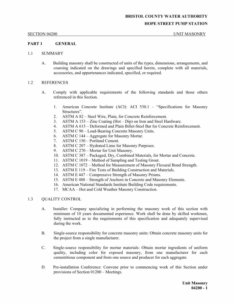
BRISTOL COUNTY WATER AUTHORITY HOPE STREET PUMP STATION
Unit Masonry 04200 - 1
SECTION 04200 UNIT MASONRY PART 1 GENERAL 1.1 SUMMARY
A. Building masonry shall be constructed of units of the types, dimensions, arrangements, and coursing indicated on the drawings and specified herein, complete with all materials, accessories, and appurtenances indicated, specified, or required.
1.2 REFERENCES
A. Comply with applicable requirements of the following standards and those others referenced in this Section.
1. American Concrete Institute (ACI): ACI 530.1 – “Specifications for Masonry
Structures”. 2. ASTM A 82 – Steel Wire, Plain, for Concrete Reinforcement. 3. ASTM A 153 – Zinc Coating (Hot – Dip) on Iron and Steel Hardware. 4. ASTM A 615 – Deformed and Plain Billet-Steel Bar for Concrete Reinforcement. 5. ASTM C 90 – Load-Bearing Concrete Masonry Units. 6. ASTM C 144 – Aggregate for Masonry Mortar. 7. ASTM C 150 – Portland Cement. 8. ASTM C 207 – Hydrated Lime for Masonry Purposes. 9. ASTM C 270 – Mortar for Unit Masonry. 10. ASTM C 387 – Packaged, Dry, Combined Materials, for Mortar and Concrete. 11. ASTM C 1019 – Method of Sampling and Testing Grout. 12. ASTM C 1072 – Method for Measurement of Masonry Flexural Bond Strength. 13. ASTM E 119 – Fire Tests of Building Construction and Materials. 14. ASTM E 447 – Compressive Strength of Masonry Prisms. 15. ASTM E 488 – Strength of Anchors in Concrete and Masonry Elements. 16. American National Standards Institute Building Code requirements. 17. MCAA – Hot and Cold Weather Masonry Construction.
1.3 QUALITY CONTROL
A. Installer: Company specializing in performing the masonry work of this section with minimum of 10 years documented experience. Work shall be done by skilled workmen, fully instructed as to the requirements of this specification and adequately supervised during the work.
B. Single-source responsibility for concrete masonry units: Obtain concrete masonry units for the project from a single manufacturer.
C. Single-source responsibility for mortar materials: Obtain mortar ingredients of uniform
quality, including color for exposed masonry, from one manufacturer for each cementitious component and from one source and producer for each aggregate.
D. Pre-installation Conference: Convene prior to commencing work of this Section under
provisions of Section 01200 – Meetings.

BRISTOL COUNTY WATER AUTHORITY HOPE STREET PUMP STATION
Unit Masonry 04200 - 2
E. Refer to PART 3.00 of this specification for additional quality control requirements. 1.4 SUBMITTALS
A. Before masonry construction is begun, the following drawings, data, specimens, and samples shall be submitted in accordance with the submittals section. If the source of a material is changed during the course of the work, the tests and reports required for preliminary review of that material shall be resubmitted.
1. Specimens of the masonry units which will be used in project construction, showing
range of finishes and dimensions. 2. One sample, at least 6 inches long, of each type of non-masonry joint material
required. 3. Results of tests conducted on masonry units in accordance with ASTM C140. 4. Types and proportions of the ingredients of grout and mortar mixtures. 5. Shop drawings or manufacturers' literature showing details of anchors, ties, and metal
accessories to be used in masonry construction. 6. Manufacturer's literature and data for any admixture added to the block, grout, and/or
mortar. 7. Hot or cold weather construction procedures per ACI 530.1 requirements.
B. The manufacturer of the masonry units shall submit a letter of certification at the time of, or prior to, delivery of the units to the jobsite to verify the units comply with the requirements of this section.
C. The supplier of the grout shall submit a letter of certification at the time of, or prior to,
delivery of the grout to the jobsite to verify the grout complies with the requirements of this section.
D. The supplier of the mortar shall submit a letter of certification at the time of, or prior to,
delivery of the mortar to the jobsite to verify the mortar complies with the requirements of this section.
1.5 DELIVERY, STORAGE AND HANDLING
A. All masonry units shall be handled in a manner which will prevent soiling, chipping, or damage of any kind. Broken, chipped, or otherwise damaged units will be rejected and shall be replaced with undamaged units.
B. Masonry units shall be stored on pallets, shall be protected against contamination and
staining, and shall be kept covered and dry at all times. Lime and cement shall be stored under cover in a dry place.
C. Sand shall be stored so that the inclusion of foreign materials is prevented. Whenever sand
is piled directly on the ground, the surface beneath the sand shall be smooth, well drained, and free from dust, mud, and debris. The bottom 6 inches of each pile shall not be used in mortar. Insulation shall be stored under cover in a dry place and shall be protected from the weather at all times.

BRISTOL COUNTY WATER AUTHORITY HOPE STREET PUMP STATION
Unit Masonry 04200 - 3
D. Remove any damaged or contaminated materials from job site immediately, including materials in broken packages, packages containing water marks, or which show other evidence of damage, unless Engineer specifically authorizes correction thereof and usage on project.
1.6 COORDINATION
A. Coordinate work with that of other trades which require placement and building-in of as work progresses including, but not limited to: anchor bolts, wood blocking, hollow metal frames, louver units, and anchorage items.
B. Examine all Drawings as to requirements for the accommodation of work of other trades.
Provide all required recesses, chases, slots, and cutouts. Place anchors, bolts, sleeves and other items occurring in the masonry work. Take every precaution to minimize future cutting and patching. Closely coordinate the location and placement of such items.
PART 2 PRODUCTS 2.1 CONCRETE MASONRY UNITS
A. Load bearing hollow and solid, normal weight concrete masonry units: Conform to ASTM C90, Type 1, normal weight, 2-core, 58 percent solid. Provide blocks with fire-resistant classification as indicated on the Drawings.
1. Exterior walls: Units of nominal thickness indicated on the Drawings, nominal 8 by
16 inch face dimension sound, true to plane and line, and free from chips, cracks and other defects. Color to be selected by Engineer/Owner from manufacturer’s standard color palette.
2. Interior partition walls: Plain-faced units of nominal thickness indicated on the Drawings, nominal 8 by 16 inch face dimension with light gray color and uniform medium-fine texture, sound, true to plane and line, and free from chips, cracks and other defects.
3. At door jambs, provide a bullnose interior corner as indicated on the Drawings. 4. Recycled content: Use maximum available percentage of recycled materials.
Concrete masonry units incorporated into the work shall contain not less than 3 percent of recycled content.
B. Aggregate: sand and gravel: conform to ASTM C 331.
C. Unit Compressive Strength: Provide units with minimum average net-area compressive
strength of 2,800 psi. D. Moisture content for average of 3 units, when delivered, not exceeding 35 percent of the
total absorption, when tested in accordance with ASTM C 140. E. Use open end high strength concrete masonry units and slot type strength concrete
masonry units as required for reinforced masonry construction. Conform to all requirements for load-bearing units specified above.

BRISTOL COUNTY WATER AUTHORITY HOPE STREET PUMP STATION
Unit Masonry 04200 - 4
2.2 MORTAR
A. Mortar: Site-mixed Portland cement mortar complying with ASTM C270 as specified herein.
B. Mortar materials for site mixed mortar:
1. Portland cement for masonry conforming to ASTM C150, Type 1, non-staining, without air entrainment. Use type III as necessary for laying masonry in cold weather. For exterior walls, mortar color shall be selected by the Engineer/Owner from the manufacturer’s standard color palette. For interior partitions, use gray color Portland cement.
2. Aggregates for grout: Conforming to ASTM C 144 for fine aggregate and ASTM C 404, Size 8 or 89.
3. Aggregate for concrete masonry mortar: Clean, washed uniformly well graded sand conforming to ASTM C 144, with the following gradation, and having a fineness modulus between 2.15 and 2.35:
Sieve Size Percentage Passing
#4 100% #8 95 to 100% #16 70 to 100% #30 40 to 75% #50 10 to 35% #100 2 to 15% #200 0 to 5%
4. Mortar pigments: Commercial alkali-resistant, non-fading mortar pigments, oxides of iron where feasible, synthetic type, equal to products of:
Davis Colors, Beltsville, MD. Solomon Grind-Chem Service, Inc., Springfield, IL. Landers Segal Color, Inc., Passaic New Jersey.
5. Lime: Approved brand plastic hydrated lime, conforming to ASTM C 207, Type “S”.
6. Water: Clean and fresh without contaminants.
C. Mortar types:
1. Mortar for masonry below grade or in contact with earth: ASTM C 270 type M using the property specification.
2. Mortar for load bearing masonry: ASTM C270 type S using the property specifications.
3. Mortar for non-load bearing masonry above grade: ASTM C 270 type N using the property specification.

BRISTOL COUNTY WATER AUTHORITY HOPE STREET PUMP STATION
Unit Masonry 04200 - 5
2.3 GROUT MIXES
A. Prepackaged grout (ready mix) complying with ASTM C 1107, or site-mixed Portland cement grout complying with ASTM C 476 may be used. 1. Five Star Products, Inc., product “Five Star Grout:” 2. L&M Construction Chemicals Inc., product “Crystex”. 3. Symons Corporation, DesPlaines, Il, product “Symons Multi-Purpose Grout”.
B. Grout for bond beams and lintels: Fine grout having a comprehensive strength of 2,500 pounds per square inch at 28 days; slump 8 to 10 inches.
2.4 REINFORCEMENT AND ANCHORAGE MATERIALS
A. Single wythe longitudinal reinforcement for concrete masonry unit walls in overall width
1-5/8 inches less than the overall wall thickness, as manufactured by Dur-O-Wal, Hohmann, AA Wire, or equal. Size, type, and coating as indicated on the drawings.
B. Reinforcing steel, additional to rods which are embedded in concrete: Solid steel
reinforcing bars, conforming to ASTM A 615, Grade 60, of sizes indicated on the Drawings.
2.5 ACCESSORIES
A. Compressible filler: Closed cell polyvinyl chloride; oversized 50 percent to joint width; self-expanding, continuous in length, and in width to fill the joint to a point ¾ inch back from each face of wall or partition.
B. Premolded control joints for concrete masonry construction: Solid rubber of profile as
indicated (to maintain lateral stability of wall), 60-80 shore A hardness. C. Cleaning solution: Non-acidic, not harmful to masonry work or adjacent materials.
2.6 MIXING MORTARS AND GROUT
A. General: Mix mortar and grout in accordance with the requirements of ASTM C270, ASTM C94, and ASTM C476 as applicable:
1. Control batching procedure to ensure proper proportions by measuring materials by
volume, amount of mixing water and mortar consistency shall be controlled by mason.
2. Control batch sizes to allow for use within manufacturer’s recommended pot life. 3. Retempering will be permitted only within the first two hours of initial mix or
shorter times as directed by manufacturers. 4. Discard all mortar and grout which exceeds the time limits allowed by the
manufacturer. Discard mortar that has partially set. B. Maintain sand; uniformly damp immediately before mixing process.

BRISTOL COUNTY WATER AUTHORITY HOPE STREET PUMP STATION
Unit Masonry 04200 - 6
C. Add mortar color and admixtures in accordance with manufacturer’s instructions. Provide uniformity of mix and coloration.
D. Do not use anti-freeze compounds to lower the freezing point of mortar or grout. E. Pouring grout shall be fluid consistency (as fluid as possible for pouring without
separation of constituent parts). PART 3 EXECUTION
3.1 MORTAR JOINTS
A. Masonry shall be laid in straight, level, uniform courses, with mortar joints of uniform
width. Head joints shall approximately equal the horizontal joints in width.
B. In laying up concrete block masonry, abutting surfaces of head joints shall be completely and solidly cemented together with mortar. All solid masonry units and hollow units with horizontal cells shall be laid on a full bed of mortar. All unfilled hollow masonry units with vertical cells shall be laid with face shell mortar bedding, except that starter courses shall be laid on a full bed of mortar. Web joints of all cores which will be subsequently filled with grout fill shall be fully mortared.
C. The filling of masonry joints shall mean that the entire space between abutting surfaces of
units is full, and that the body of the mortar is forced against and into the porous surface of each unit.
D. All exterior and exposed interior mortar joints shall be tooled to a smooth uniform surface
and shall be finished free of voids using a rounded tool. Mortar joints specified to be caulked shall be raked to a depth of 1/2 inch. Tooling of joints shall be regulated so that the mortar for each wall space has a uniform appearance.
E. Cement shall be wiped from block edges and the joints shall be saturated with clean water.
Joints shall be filled solidly with pointing mortar, using a rubber-faced trowel to spread the mortar and to remove the excess. After all joints are filled flush with the face of the block, excess mortar shall be wiped from the surface with a clean, flat sponge. Joints shall be tooled while the mortar is still workable, using a rounded tool at least 1 inch in diameter. The tooled joints shall be nearly flat, only slightly concave.
3.2 BONDING AND REINFORCING
A. All concrete block shall be laid in running bond. All masonry shall be reinforced and
anchored as indicated on the drawings and as specified herein.
B. Unless otherwise specified, all concrete block masonry shall be bonded and reinforced with continuous ladder type joint reinforcement spaced not more than 16 inches apart vertically. The joint reinforcement shall have one longitudinal rod at each face shell of the masonry units.
C. Except where bond beams are indicated on the drawings, the top three courses of all
masonry walls shall have continuous joint reinforcement placed in each joint (8 inches on centers). Joint reinforcement shall be terminated at expansion joints and control joints.

BRISTOL COUNTY WATER AUTHORITY HOPE STREET PUMP STATION
Unit Masonry 04200 - 7
Openings in masonry walls shall have the lintel reinforcement extend at least 12 inches beyond each side of the opening. Install continuous joint reinforcement in the mortar joint below the sill. Joint reinforcement shall be continuous between control joints.
D. All joint reinforcement shall be fully embedded in mortar and shall be covered with at
least 5/8 inch of mortar on the exterior face.
E. The ends of sections of joint reinforcement shall be lapped at least 8 inches. Joint reinforcement shall be lapped full width at corners and intersections, or prefabricated corners and tees shall be used.
F. Concrete block bond beam units shall be provided, installed, and reinforced with
reinforcing steel where required and as indicated on the drawings. Bond beam units shall be filled with grout fill as specified herein. Reinforcing steel shall be continuous around corners, and all laps shall have a minimum length of 48 bar diameters.
G. Vertically reinforced concrete block cores shall be provided as indicated on the drawings.
Reinforcing shall be accurately placed and securely tied to prevent shifting during core filling. All lap splices shall have a minimum length of 48 bar diameters. Mortar fins which project into cores more than 1/2 inch and all loose mortar and debris shall be removed before filling the cores. Cores shall be filled with grout fill as specified herein.
3.3 GROUT FILL
A. Unless otherwise acceptable to the Engineer, grout fill shall be placed in lifts not to exceed
5 feet. Pours exceeding 12 inches in height shall be consolidated by mechanical vibration and reconsolidated after initial water loss and settlement. Bond beam fill shall not be mechanically vibrated. Grout fill shall be placed in reinforced block cores, bond beams, lintels, and in other locations indicated on the drawings. All concrete masonry shall be completely filled with grout.
3.4 LAYING MASONRY UNITS
A. All masonry units shall be free from dust, dirt, and surface moisture when laid. Concrete blocks shall be dry when laid.
B. All masonry shall be laid to a line. Walls shall be plumb and straight and in level courses.
At no time shall any part of masonry construction project more than 8 feet above adjacent work. When work is suspended, the tops of exterior masonry walls shall be covered and protected from the weather.
B. Only whole, undamaged units shall be used in corners and at jambs, to maintain
uniformity of appearance.
C. Provide inverted u-blocks or lintel blocks at windowsills in accordance with the Drawings. D. Masonry units laid in running bond in exposed locations shall be so constructed that
vertical joints in alternate courses lie in the same vertical lines, midway between the vertical joints in adjacent courses.

BRISTOL COUNTY WATER AUTHORITY HOPE STREET PUMP STATION
Unit Masonry 04200 - 8
E. Masonry units shall be saw-cut to provide openings and to accommodate embedded items. Anchors shall be securely embedded in mortar. Door and window frames shall be maintained plumb and true. Masonry shall be built tightly against interior doorframes. A caulking space shall be provided between exterior doorframes and masonry in accordance with the details indicated on the drawings. The jambs of built-in hollow metal doorframes shall be completely filled with grout fill or mortar.
F. Lintels shall be provided over all openings wider than the length of a masonry unit.
Lintels shall be of the types and sizes indicated on the drawings or as required and shall be acceptable to the Engineer. Lintels longer than 3 feet shall bear on solid masonry units or on grout-filled cells of hollow units at least one masonry course in height, unless otherwise indicated on the drawings.
G. All embedded items shall be set and securely anchored in the masonry work as indicated
on the drawings or as acceptable to the Engineer. Joints between masonry and embedded items shall be pointed.
H. Masonry units shall be selected and laid so that the exposed face of each unit is free of
broken corners, chipped edges, or other defects which would be detrimental to the appearance of the wall surface.
3.5 CONTROL JOINTS
A. Control joints in masonry walls and in masonry walls abutting concrete wall surfaces shall be constructed as indicated on the drawings. Joint material shall be at least 4 inches wide and shall have a thickness equal to at least 1-1/2 times the nominal width of the joint. The joint material shall be firmly bonded to one joint face by the adhesive backing, held back 1/2 inch for caulking, and placed under compression by the abutting masonry. All joints in filler strips shall be tightly butted.
B. Control joints shall be placed at locations shown on the drawings.
3.6 ANCHORS AND INSERTS
A. All necessary ties, anchors, bolts, inserts, bucks, flashings, sleeves for piping, conduits of every kind, window and door frames, and other work shall be accurately set and securely held in the masonry work as indicated on the drawings or in a manner acceptable to the Engineer. Sleeves shall be provided where small piping passes through the masonry.
3.8 LOW TEMPERATURES
A. When the temperature of the surrounding air is below 40F, or when the outdoor temperature is likely to fall below freezing at any time during the 24 hour day, the following precautions shall be taken to prevent freshly laid masonry from freezing:
1. In addition to the protection specified for ordinary conditions, masonry materials
shall also be kept from contact with snow, ice, or dampness of any kind. 2. The temperature of the mixed mortar shall be between 70 and 120F. Mixing water
shall be warm, but not above 165F. If necessary, sand shall be heated also. Mortar mixing equipment shall be heated before it is used. The use of salt or calcium chloride is not acceptable.

BRISTOL COUNTY WATER AUTHORITY HOPE STREET PUMP STATION
Unit Masonry 04200 - 9
3. Masonry units shall be free of ice and snow and shall be above freezing when laid. If the outdoor temperature is below 30F, units shall be heated to at least 40F. If the temperature is below 0F, units shall be heated to at least 60F. Heating shall be done so that the units are not damaged.
4. Masonry units shall not be laid on surfaces that are frozen or covered with snow or ice.
5. Masonry laid during freezing weather shall be kept warm for at least 3 days after laying. The air temperature at the masonry surface shall be kept between 45 and 90F, using heating methods that will not unduly dry out or otherwise damage the masonry. Heat shall be applied to both sides of the wall, with provisions for proper circulation of air. The masonry shall be suitably housed or covered.
3.9 HIGH TEMPERATURES
A. When the ambient air temperature exceeds 99F in the shade and the relative humidity is less than 50 percent, masonry shall be protected from direct exposure to wind and sun during and for 48 hours after erection.
3.10 FINISH POINTING
A. On completion of the work, all exposed masonry shall be pointed where necessary and all voids and holes in the mortar shall be filled to match adjacent joint surfaces. Defective joints shall be cut out and repointed with mortar. Care shall be taken to produce a uniform overall appearance. Spottiness due to variations in either materials or workmanship will not be acceptable.
3.11 PROTECTION FROM DAMAGE
A. Masonry and all embedded or built-in items shall be carefully protected from damage. Masonry walls discolored by paint, mortar, or concrete shall be rebuilt with new materials.
B. Where concrete is placed adjacent to previously constructed masonry, the masonry shall
be adequately protected against splashing of concrete paste and from other damage. C. Where concrete is placed on top of previously constructed masonry, the masonry shall be
protected from splashing and spilling of concrete and penetration of water with polyethylene film or Sisalkraft paper placed on top of the masonry and extended down each side of the wall as required. The protective covering shall be neatly trimmed away at face of the wall after form removal.
3.12 CLEANING
A. Following finish pointing, all exposed masonry surfaces shall be cleaned to remove all surface stains and smears.
B. Mortar smears or droppings on concrete blocks shall be removed with a steel trowel after
they have hardened to the extent that removal will not cause additional smearing. Any remaining mortar shall be removed to the extent possible by rubbing with a small piece of block. All surfaces shall then be thoroughly brushed.

BRISTOL COUNTY WATER AUTHORITY HOPE STREET PUMP STATION
Unit Masonry 04200 - 10
3.13 SOURCE AND FIELD QUALITY CONTROL
A. Material source and field inspection shall be performed under the provisions of Section 01400 – Quality Control.
B. Testing frequency: Material source (source quality control) tests shall be required for each
different material indicated or proposed for use at the site. Field Quality Control tests and evaluations listed in this article shall be performed during construction for each 500 square feet of wall area or portion thereof.
C. Concrete Masonry Unit Tests: For each different concrete masonry unit indicated, units
shall be tested for: strength, absorption, and moisture content per ASTM C140.
D. Mortar properties shall be tested per property specification of ASTM C 270. E. Mortar composition and properties shall be evaluated per ASTM C 780.
F. Grout compressive strength shall be sampled and tested per ASTM C 1019.
1. Prior to grouting, request inspection of all voids to be grouted.
G. Reinforcement installation and placement shall be verified for conformance with the
construction documents.
H. Evaluation of Quality Control tests: In absence of other indications of noncompliance with requirements, masonry will be considered satisfactory if results from construction quality control tests comply with minimum requirements indicated.
3.13 TOLERANCES
A. Maximum variation from true surface level for exposed to view walls and partitions: 3.13.1.1 Unit-to-unit tolerance: 1/16 inch. 3.13.1.2 Surface, overall tolerance: 1/4 inch in 10 feet in any direction and 1/2 inch
in 20 feet or more.
B. Maximum variation from plumb: For lines and surfaces of walls do not exceed 1/4 inch in 10 feet, 3/8 inch in any story up to 20 feet maximum. At expansion joints and other conspicuous lines, do not exceed 1/4 inch in 20 feet.
C. Maximum variation from level: For lines of sills, tops of walls and other conspicuous
lines, do not exceed 1/8 inch in 3 feet, or 1/4 inch in 10 feet and 1/2 inch in 30 feet.
D. Maximum variation of linear building line: For position shown in plan relating to columns, walls and partitions, do not exceed 1/2 inch in 20 feet or 3/4 inch in 40 feet.
E. Maximum variation in specified height: 1/2 inch per story.
F. Maximum variation of joint thickness: 1/8 inch in 3 feet.
END OF SECTION

BRISTOL COUNTY WATER AUTHORITY
HOPE STREET PUMP STATION
DIVISION 11
EQUIPMENT
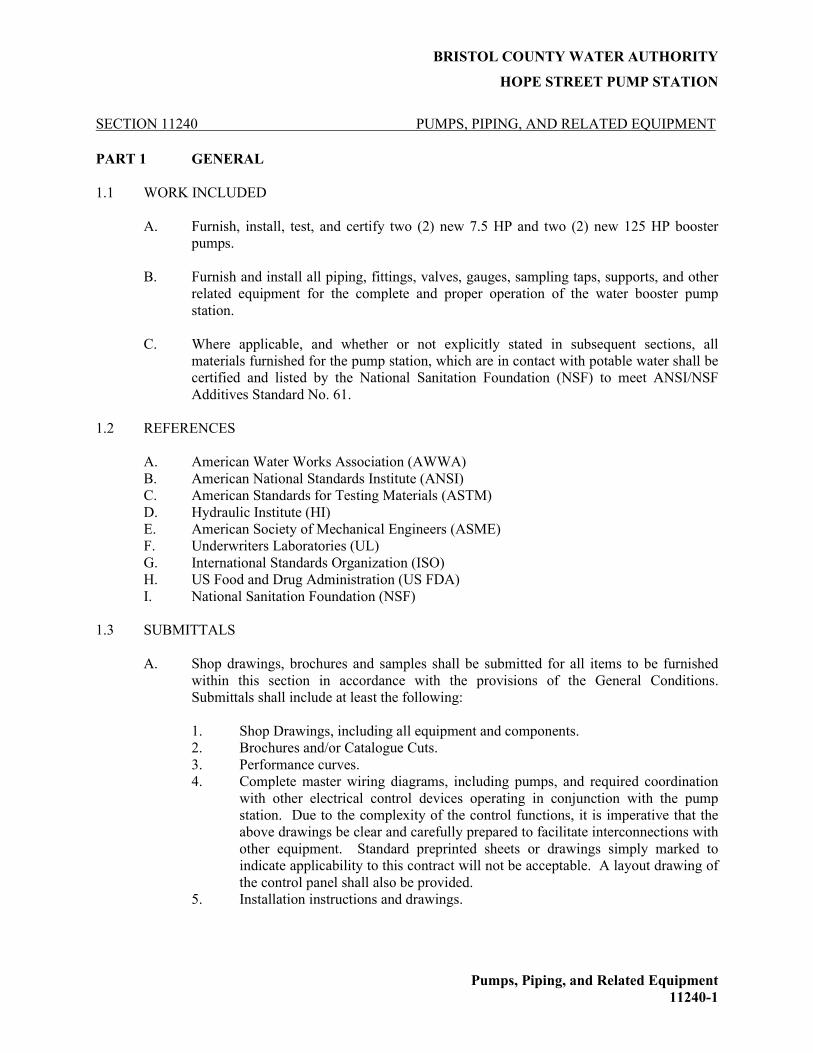
BRISTOL COUNTY WATER AUTHORITY
HOPE STREET PUMP STATION
Pumps, Piping, and Related Equipment
11240-1
SECTION 11240 PUMPS, PIPING, AND RELATED EQUIPMENT
PART 1 GENERAL
1.1 WORK INCLUDED
A. Furnish, install, test, and certify two (2) new 7.5 HP and two (2) new 125 HP booster
pumps.
B. Furnish and install all piping, fittings, valves, gauges, sampling taps, supports, and other
related equipment for the complete and proper operation of the water booster pump
station.
C. Where applicable, and whether or not explicitly stated in subsequent sections, all
materials furnished for the pump station, which are in contact with potable water shall be
certified and listed by the National Sanitation Foundation (NSF) to meet ANSI/NSF
Additives Standard No. 61.
1.2 REFERENCES
A. American Water Works Association (AWWA)
B. American National Standards Institute (ANSI)
C. American Standards for Testing Materials (ASTM)
D. Hydraulic Institute (HI)
E. American Society of Mechanical Engineers (ASME)
F. Underwriters Laboratories (UL)
G. International Standards Organization (ISO)
H. US Food and Drug Administration (US FDA)
I. National Sanitation Foundation (NSF)
1.3 SUBMITTALS
A. Shop drawings, brochures and samples shall be submitted for all items to be furnished
within this section in accordance with the provisions of the General Conditions.
Submittals shall include at least the following:
1. Shop Drawings, including all equipment and components.
2. Brochures and/or Catalogue Cuts.
3. Performance curves.
4. Complete master wiring diagrams, including pumps, and required coordination
with other electrical control devices operating in conjunction with the pump
station. Due to the complexity of the control functions, it is imperative that the
above drawings be clear and carefully prepared to facilitate interconnections with
other equipment. Standard preprinted sheets or drawings simply marked to
indicate applicability to this contract will not be acceptable. A layout drawing of
the control panel shall also be provided.
5. Installation instructions and drawings.
BRISTOL COUNTY WATER AUTHORITY
HOPE STREET PUMP STATION
Pumps, Piping, and Related Equipment
11240-2
6. Operation and Maintenance Manual of the pumping station including all
equipment and components. Manual shall also list all major parts with model
numbers.
7. A pump test report shall be provided prior to shipment from the factory. The test
shall be performed by the pump manufacturer to certify that the pumps were
inspected and tested in accordance with Hydraulic Institute type B standards.
The test shall include the following:
a. A check of the motor voltage and frequency as shown on the name plate.
b. A motor and cable insulation test for moisture content or insulation
defects per UL criteria.
c. Pump flow tests performed by running the pumps to determine that the
units meet three pre-determined hydraulic performance points.
8. A startup test report shall be provided upon installation. The test shall be
performed by a qualified representative of the manufacturer. At a minimum, the
test shall confirm the flow rate of each pump installed against the normal head in
the system. The startup report must be completed and accepted prior to final
acceptance of the pump(s).
9. A certified factory performance test shall be performed on each pumping unit in
accordance with Hydraulic Institute Standards, latest edition. Tests shall be
sufficient to determine the curves of head, input horsepower, and efficiency
relative to capacity from shutoff to 150% of design flow. A minimum of six
points, including shutoff, shall be taken for each test. At least one point of the
six shall be taken as near as possible to each specified condition. The use of
affinity laws shall not be used in place of actual pump curve testing of each
pump.
1.4 QUALITY ASSURANCE
A. All like materials shall be furnished by a single supplier entity, which shall have
responsibility for the manufactured goods provided.
B. Qualifications
1. Upon request from the engineer the manufacturer must provide proof or evidence
of facilities, equipment and capabilities required to produce the specified
materials and equipment.
2. Provide pumping station certified testing.
3. Manufacturer shall provide a tour of their production and test facility at the
request of the customer or engineer.
C. Warranty
1. All pump equipment shall be provided with a 3-year manufacturer’s warranty
against all defects in material and workmanship, in accordance with section 3.5,
below.
2. The Contractor shall provide a 1-year warranty for the entire station, including all
equipment, materials, and workmanship. Any defects in the station, faulty
equipment, or problems that prevent the continuous use of the station shall be
BRISTOL COUNTY WATER AUTHORITY
HOPE STREET PUMP STATION
Pumps, Piping, and Related Equipment
11240-3
repaired by the Contractor at no cost to the Owner. Warranty period shall begin
at substantial completion.
1.5 SCHEDULING
A. The equipment manufacturer(s) shall provide the following:
1. Estimated FOB delivery.
2. Estimated NET weights.
3. Unloading instructions.
4. Acceptance at site procedures.
5. On-site storage and protection information, and complete instruction manuals.
1.6 PUMP START-UP SERVICE
A. When discharge piping, electrical connections, and electrical inspection have been
completed, the pump manufacturer/sales representative shall be contacted for start up.
During start up, the complete pumping system shall be given a running test of normal
start and stop, and fully loaded operating conditions. During this test, each pump shall
demonstrate its ability to operate without undue vibration, or overheating, and shall
demonstrate its general fitness for service. All defects shall be corrected and adjustments
shall be made to the pumping equipment for satisfactory operation. System problems or
concerns will be corrected by the general contractor or site station staff, in conjunction
with the appropriate factory representative. Testing shall be repeated until satisfactory
results are obtained, as determined by the engineer.
PART 2 PRODUCTS
2.1 PUMPS
A. The contractor shall furnish two (2) “regular duty” pumps, 7.5 HP, and two (2) “high
flow” pumps, 125 HP.
B. The regular duty pumps shall be Pentair Aurora Model 382B-CC (1.5x1.5x7) vertical
close coupled in-line centrifugal pumps each suitable for operation with a VFD. Pumps
shall have a 1.5-inch suction inlet and a 1.5-inch discharge outlet. Suction/discharge
flange connections and casing rotation shall be 125 Class ANSI for piping connection
versatility.
The high flow pumps shall be Pentair Aurora Model 3804 (4x5x9.5) centrifugal
horizontal flexible-coupled end suction base mounted pumps each suitable for operation
with a VFD. Pumps shall have a 5-inch suction inlet and a 4-inch discharge outlet.
Suction/discharge flange connections and casing rotation shall be 125 Class ANSI for
piping connection versatility.
C. The regular duty pumps shall have a design point of 100 gpm at 125 feet of TDH. The
high flow pumps shall have a design point of 1,500 gpm at 245 feet of TDH.
D. The pump motor efficiency shall meet or exceed those set by National Grid to be
included in their Premium Efficiency Motor Initiative.

BRISTOL COUNTY WATER AUTHORITY
HOPE STREET PUMP STATION
Pumps, Piping, and Related Equipment
11240-4
E. Elastomers shall be Viton.
2.2 PUMP/MOTOR VIBRATION ISOLATION PADS
A. The pump/motor assembly shall be mounted to new concrete pedestals. Each mounting
or attachment point shall be complete with a vibration isolation pad. The pad will be in
two (2) parts, a 1/4" base layer followed by a 5/8" upper layer and be a nominal 2" x 2"
square size for pump/motor combinations weighing up to 1,500 pounds.
2.3 ELASTOMER PIPE CONNECTOR
A. The inlet and outlet side of each booster pump shall include an elastomer connector to
help isolate vibration and noise in the piping system. The elastomer connector shall be of
single sphere design, constructed of neoprene and nylon with bias-ply tire reinforcing
cord to provide a 225 psi working pressure rating to a minimum of 120˚F. The elastomer
connector shall pass through the plate steel flanges designed to grip the connector so the
connector seals without gaskets when the flange bolts are drawn up.
B. A control joint limiting pipe connector movement shall be supplied with each pipe
connector.
2.4 INTERIOR DUCTILE IRON PIPE
A. Interior ductile iron pipe shall be Class 53, with flanged joints, and shall conform to AWWA
specifications C150, C151, and ANSI A21.51, latest revision.
B. All gaskets for use on all interior pipe, fittings, valves and other appurtenances shall be
Viton or approved equivalent for use in a chlorine environment.
C. The exterior surfaces of all interior pipe and fittings shall be thoroughly cleaned and given
one shop coat of manufacturers recommended primer. The coating shall be compatible with
the coats to be field applied. The shop coat shall be applied in accordance with the pain
manufacturer’s recommendation.
D. Joints: Joints for pipe and fittings shall be flanged as indicated.
1. Flanges shall be drilled and faced for American 125 Standard and shall conform
to ANSI B16.1, latest revision.
2. Pipe shall have screwed-on or welded flanges. Fittings shall have integrally cast
flanges.
3. Pipe flanges shall be power tightened and refaced after installation, on both ends.
Flanges shall not be installed in the field.
4. Flanged joints shall be made with bolts or bolt studs, with a nut on each end, and
1/8-inch thick Viton gaskets extending at least to the inside of bolts. Bolts and
nuts shall be heavy, unfinished hexagon head bolts and nuts, conforming to ANSI
B18.2, latest revision. Where required, flanges shall be tapped for stud bolts.
5. The use of flange adapters, or other field installed pipe flanges will be allowed on
a limited basis for the installation and connection of equipment, as approved by
the Engineer. Adapter flanges shall be ductile-iron in accordance with ASTM

BRISTOL COUNTY WATER AUTHORITY
HOPE STREET PUMP STATION
Pumps, Piping, and Related Equipment
11240-5
A536, Grade 65-45-12, with ANSI 125-1b flange fabrication for rubber gasketed
joint installation.
E. All interior mechanical piping and equipment shall receive two coats of finish, Sherwin
Williams Macropoxy 646 PW of not less than 4.0 - 6.0 mils dry coat finish or approved
equivalent.
2.5 PIPE SUPPORT SYSTEMS
A. Pipe supports and restraints shall be adequate for the maximum test pressure specified
herein or 1.5 times the apparent working pressure, whichever is greater.
B. All piping shall be supported independent of the equipment to which it is connected. All
equipment shall be removable without needing temporary supports for adjacent piping.
C. All metallic supporting appurtenances, except those used for copper piping, and as
otherwise noted, shall be galvanized conforming to ASTM A-153 for threaded items, and
ASTM A-123 for all other items. Supporting appurtenances, when used with copper
piping, shall be copper, bronze, or PVC dipped galvanized steel. Pipe supports are to be
fully welded at the pipe, anchored to the floor, and sized for pipe elevation.
D. Piping shall be supported according to the MSS Standard Practice SP-69, (Manufacturers
Standardization Society of the Valve and Fitting Industry), whichever spacing is closer.
A support shall also be located within four inches of each side of all fittings and valves.
Vertical runs of pipe shall be supported independently of the connected horizontal runs.
All vertical pipes shall be supported at each floor or at intervals not greater than ten feet,
by approved pipe collars, claps, brackets, or wall rests.
E. Base elbows, tees and concrete pedestals shall be provided at all vertical runs of pipe and
shall be supported on a base elbow and/or concrete pedestal. All concrete supports shall
be formed up to the spring line of the pipe. After completion of curing, piping shall be
adjusted to the proper grade.
F. Pipe supports by minimum sizing for:
1. 8" and smaller piping shall be 2" x 3" x 3/16" wall rectangular tubing;
2. 10" and larger piping shall be 3" x 4" x 1/4" wall rectangular tubing;
3. 6" and larger piping shall be provided with "kick" bracing projecting fully from
the underside of the pipe to the floor at an angle of no less than 15° from vertical
out at a right angle to the run of the pipe being supported. These "kick" braces
shall be in addition to the vertical pipe supports called out above.
G. Additional supports and restraints at bends shall be installed for all pump system piping
as necessary to prevent deformation and movement of the pipe under maximum flows
and pressures.
2.6 SERVICE CONNECTIONS ON INTERNAL PIPING
A. All plumbed devices within the station eventually requiring service, such as meters,
valves, pumps and like equipment, shall be easily removed from the piping by the

BRISTOL COUNTY WATER AUTHORITY
HOPE STREET PUMP STATION
Pumps, Piping, and Related Equipment
11240-6
presence of appropriately placed and sufficient quantity of adaptors and couplings as
shown on the drawings; no less than the quantity of couplings and adaptors shown shall
be allowed.
2.7 BUTTERFLY VALVES
A. The butterfly valves shall be designed, manufactured, and tested in accordance with
AWWA Standard ANSI/AWWA C504. Flanged end connections shall fully conform
with ANSI B16.1 for Class 125 and Class 250 iron flanges. Both 125 and 250 flanges
shall be flat faced. Valve shafts shall be of the through type for sizes 4" through 24".
Size 30" and larger shall be of the stub type design. Shafts shall be locked to the disc by
O-ring sealed taper pins retained with stainless steel nuts. Valve discs shall be of the
solid type without external ribs or vanes to obstruct flow. Resilient seats shall be located
on the valve disc and shall provide a 360-degree continuous, uninterrupted seating
surface. Seats are mechanically retained with a stainless-steel retaining ring and cap
screws. The resilient seat’s mating surface shall be to a 360-degree continuous
uninterrupted stainless steel body seat ring. Sleeve bearings are provided in the valve
hubs, constructed of nylatron or woven Teflon, fiberglass backed, and shall be self-
lubricating. Shaft seals shall be of the V-type and shall be replaceable without removal
of the valve from the line or the shaft from the valve.
B. The Class 150B valve body is constructed of ASTM A126, Grade B gray iron. The Class
250B valve body is constructed of ASTM A536 Grade 65-45-12 ductile iron. Disc
material is ASTM A536 Grade 65-45-12 ductile iron. Class 150B shafts are ASTM
A276 Grade 304 stainless steel. Class 250B shafts are ASTM A564 Grade 17-4 stainless
steel. Resilient seat shall be Buna-N and mate to a Type 304 stainless steel body seat
ring.
C. Valve exteriors shall be coated with a universal alkyd primer. Valve interiors are coated
with an ANSI/NSF 61 epoxy coating approved for potable water service.
D. Manually operated valves are provided with handwheel operators.
E. Butterfly Valves shall be manufactured by Henry Pratt, or approved equivalent.
F. Butterfly valves that require electric actuation shall be equipped with AUMA actuators.
Actuators shall be capable remote operation through BCWA’s SCADA system.
2.8 PRESSURE GAUGES
A. Gauges shall be Ashcroft or approved equivalent.
B. Pressure gauges shall be glycerin filled with a built-in pressure snubber and have 4-½
inch minimum diameter faces and be turret style, stainless steel case with clear glass face.
The movement shall be rotary, of 400 Series stainless steel with Teflon coated pinion
gear and segment. The gauge shall be bottom connected and accept a 1/4" NPT female
thread. Combination pressure gauge range and scale graduations shall be in psi and
inches of mercury as follows:
BRISTOL COUNTY WATER AUTHORITY
HOPE STREET PUMP STATION
Pumps, Piping, and Related Equipment
11240-7
SUCTION PRESSURE – 30-inches of vacuum to 40 psi. Vacuum intervals shall be
inches of mercury with graduating marks every 2-inches, discharge intervals shall be 2
psi with graduating marks every 1 psi.
DISCHARGE PRESSURE - 0 to 200 psi, 20 psi figure intervals, with graduating marks
every 2 psi.
C. All gauges will be provided with appropriate ball-type isolation valves and air bleeder
valves. Gauges mounted directly to the pipeline or at the sensing point will not be
accepted.
D. All gauges installed on fittings, such as tees, shall be shop-fitted to the pipe. No field
fitting shall be allowed. However, field fitting shall be allowed on straight pipe sections.
Field fit gauges shall be provided with appropriate saddles.
E. Please refer to Specification Section 13612 for information pertaining to pressure
transmitting gauges.
2.9 SAMPLE TAPS
A. Sample taps where shown on the drawings shall have right angle outlets, smooth nose,
and shall be 316L stainless steel. Stainless steel sample taps shall be installed at a height
to adequately allow BCWA personnel to easily access them; the contractor shall
coordinate this height with BCWA personnel prior to installation. Type K copper tubing
of appropriate size shall be utilized to bring the sampling taps to the appropriate height.
The Contractor shall utilize only brass fittings for all connections between copper tubing
and sample taps. The Contractor shall be required to install pipe supports every five (5)
feet to prevent movement of the sampling tap.
2.10 CHECK VALVES
A. The 4” globe check valve shall be of the silent operating type that begins to close as the
forward flow diminished and fully closes at zero velocity preventing flow reversal and
resultant water hammer. The check valve shall have flat faced flanges in accordance with
ASME B16.1 for Class 125 or Class 250 iron flanges.
B. Globe Valve body shall be constructed of ASTM A536 Grade 65-45-12 ductile iron.
Globe shall be ASTM B584 Alloy C83600 cast bronze or ASTM B148 Alloy C95200
aluminum bronze. Globe compression spring shall be ASTM A313 Type 316 stainless
steel with ground ends.
C. A resilient seal shall be provided on the Buna-N seat to provide zero leakage at both high
and low pressures without overloading or damaging the seat.
D. Valve interiors and exteriors shall be coated with an NSF/ANSI 61 certified fusion
bonded epoxy in accordance with AWWA C550.
E. The check valve shall be hydrostatically tested at 1.5 times their rated cold working
pressure and seat tested at the valve CWP.

BRISTOL COUNTY WATER AUTHORITY
HOPE STREET PUMP STATION
Pumps, Piping, and Related Equipment
11240-8
F. The check valve shall be a Val-Matic Series 1800 or approved equal.
2.11 PUMP CONTROL VALVE WITH TWO-WAY SOLENOID
A. The contractor shall provide two (2) 6-inch in-line pump control valves with one (1) pump
control valve located in the discharge piping of each high flow pump. The pump control
valve shall minimize high flow pump starting and stopping surges by placing the pump “on
line” and taking it “off line” slowly.
B. Each pump control valve shall be ruggedly constructed of first-class grey iron with a size of
6-inch, 125 lb. / 250 lb. flanged, full ported globe / angle body design. The grey iron shall be
free from cold shuts, defective or spongy spots and conforming to ASTM specification A-126
Class B with bronze or stainless-steel trim. The bronze parts shall conform to ASTM
specification B-62. The 125 lb. / 250 lb. flanged assemblies shall conform to ANSI standards
for flange thickness and drilling and wall thickness of body and caps.
C. The pump control valve shall be fully bronze mounted, external pilot operated, with a rugged
internal free-floating piston (operated without springs, diaphragm or levers), single seat with
seat bore equal to the size of valve. The seat disc, main cup plates, and main bushing shall be
bronze. Also the external pilot valve, internal piston, seat ring, stem nuts, seat packing
support, position indicator and bottom cap cylinder shall be bronze.
D. The minimum travel of the piston shall be equal to 25% of the diameter of the seat. For true
alignment (to correct lateral thrust and stem binding) the piston shall be guided above and
below the seat a distance no less than 75% of the seat diameter. The piston shall carry a
contoured cushion device that will cause a gradual change in flow area as the valve
approaches the seat. The cushion device must move with the piston to minimize head loss
when the valve is fully opened and so designed as to insure positive closure.
E. The main valve shall be packed with leather (or other soft material) to ensure tight closure
and prevent metal to metal friction and seating. The main valve shall include a position
indicator to show position of opening of the piston. The main valve will include gauge cocks
for testing purposes. The main valve shall include adjustable, independent, opening and
closing speed control valves. The main valve shall include a cam operated limit switch. The
main valve shall include a three-way solenoid valve with a manual operator.
F. The pilot valve, controlling operation of the main valve, shall have a range for adjustment, be
easily accessible and so arranged to allow for its removal from the main valve while the main
valve is under pressure. The pilot valve and all associated piping and fittings necessary for
proper operation shall be factory assembled and furnished with the pump control valve.
G. Ball valves shall be installed in the control piping to completely isolate the pilot valve when
conditions may require pilot isolation for maintenance or repair.
H. An external strainer with blow-off will be provided in the control circuit to protect the pilot
and needle valves. The design shall be such that repairs and dismantling internally of the
main valve may be made without its removal from the line.

BRISTOL COUNTY WATER AUTHORITY
HOPE STREET PUMP STATION
Pumps, Piping, and Related Equipment
11240-9
I. The pump control valves shall be Model Number 42WRS-SO as manufactured by the Ross
Valve Manufacturing Company. Each pump control valve shall have a dedicated control
panel for proper operation.
J. The pump control valves shall allow for manual operation as well as Auto via SCADA.
PART 3 EXECUTION
3.1 SURFACE CONDITIONS
A. Prior to all work of this section, carefully inspect the installed work of all other trades and
verify that all such work is complete to the point where this installation may properly
commence.
B. Verify that all equipment is properly installed in accordance with all pertinent codes and
regulations, the original design, and the referenced standards. In the event of
discrepancies, immediately notify the Engineer.
C. Do not proceed with installation in areas of discrepancy until all such discrepancies have
been fully resolved.
3.2 DISINFECTION
A. Disinfection shall be done in accordance with specification Section 02704.
3.3 FIELD ACCEPTANCE TESTS
A. After installation of equipment and after completion of the services of manufacturer’s
representative, operate each unit, in the presence of the Engineer, to demonstrate its
ability to pump without excessive vibration, motor overloading, or overheating. Operate
each pump for a sufficient period, as determined by the Engineer, to permit thorough
observation of all pump components. Verify proper sequence and operation of all
controls. Each pump, at a minimum, shall be operated at their shut off point, design
point, and a point of 20% greater flow than their respective design point to determine if
the pumps operate on their respective curve. It shall be the contractor’s responsibility to
provide all pressure gauges and other appurtenances, if necessary, for these tests. Notify
the Engineer four weeks in advance of field acceptance tests.
B. Correct all defects or replace all defective equipment promptly, at no expense to Owner.
C. Make all final adjustments necessary to place equipment in satisfactorily working order at
time of above tests.
D. After installation, test all piping for tightness under a pressure of 150 psi. Should leaks
be found, repair faulty joints even to extent of disassembling and remaking joint and
remove and replace all defective pipe and fittings in a manner satisfactory to Engineer.
3.4 OPERATION AND MAINTENANCE MANUALS
A. The equipment supplier shall prepare an operation and maintenance manual covering:
BRISTOL COUNTY WATER AUTHORITY
HOPE STREET PUMP STATION
Pumps, Piping, and Related Equipment
11240-10
1. Equipment function, normal operating characteristics and limiting conditions.
2. Assembly, installation, alignment, adjustment and checking instruction.
3. Operating instructions for start-up, routine and normal operation, regulation and
control, shutdown and emergency conditions.
4. Lubrication and maintenance instructions.
5. Guide to “troubleshooting”.
6. Parts lists and predicted life of parts subject to wear.
7. Outline, cross-section and assembly drawings; engineering data; and wiring
diagrams.
8. Test data and performance curves, where applicable.
B. The operation and maintenance manuals shall be in addition to any instructions of parts
lists packed with or attached to the equipment when delivered.
C. Manuals shall be printed on heavy, first quality paper, 8 ½ x 11-inch size with standard 3-
hole punching. Drawings and diagrams shall be reduced to 8 ½ x 11 inches or 11 x 17
inches. Where reduction is not practical, larger drawings shall be folded separately and
placed in envelopes that are bound into the manuals. Each envelope shall bear suitable
identification on the outside.
3.5 MANUFACTURER’S WARRANTY
A. The warranty is the sole responsibility of the equipment manufacturer and that
manufacturer's warranty shall be provided in written form for inclusion with both the
submittal covering the specified equipment and the O&M manuals provided with that
equipment.
B. Said manufacturer's warranty shall at a minimum cover:
1. A period of three (3) years commencing upon successful start-up, after
authorized manufacturer's start-up, not to exceed forty-eight (48) months from
the date of shipment.
2. The one (1) year period shall be inviolate regardless of any component
manufacturer's warranty for equipment and components within the station.
3.6 SPARE PARTS
A. The pump manufacturer shall include one (1) each complete pumping unit for the regular
duty pumps and the high flow pumps, assembled but uninstalled, for the Owner to store
off-site.
END OF SECTION

BRISTOL COUNTY WATER AUTHORITY
HOPE STREET PUMP STATION
Chlorine Injection Pumps and Related Equipment
11300 - 1
SECTION 11300 CHLORINE INJECTION PUMPS AND RELATED EQUIPMENT
PART 1 GENERAL
1.1 WORK INCLUDED
A. The work of this section includes furnishing all labor, materials, tools and equipment
necessary to furnish and install chlorine injection pumps and all related equipment as
specified herein and as shown on the drawings, including:
1. Chlorine injection pumps and control panels;
2. Chlorine storage and handling equipment;
3. Static mixer;
4. Piping, tubing, and valves;
5. Pre and Post Injection chlorine analyzers;
6. Liquid level sensing equipment and scales; and
7. Related Equipment.
B. All materials included in this section, whether or not specifically identified in the
subsections of this specification that are to come into contact with potable water shall be
NSF 61 or NSF 60 approved, as applicable.
C. It is the intent of this specification to address the major elements of a chlorine-based
disinfection system, and not every single piece of equipment that may be required to
provide a complete and functional system. Other equipment not specifically identified in
this section but necessary to provide a complete and operational chlorine-based
disinfection system is considered incidental to the construction of this system.
1.2 RELATED WORK
A. Section 02200: Earthwork
B. Section 02704 – Pipeline Pressure, Leakage, and Disinfection
C. Section 02640: Valves, Tapping Sleeves, and Appurtenances
D. Section 02616: Ductile Iron Pipe and Fittings
1.3 REFERENCES
A. American National Standards Institute (ANSI)
B. American Standards for Testing Materials (ASTM)
C. Hydraulic Institute (HI)
D. American Society of Mechanical Engineers (ASME)
E. Underwriters Laboratories (UL)

BRISTOL COUNTY WATER AUTHORITY
HOPE STREET PUMP STATION
Chlorine Injection Pumps and Related Equipment
11300 - 2
F. International Standards Organization (ISO)
G. ASTM D883: Standard Terminology Related to Plastics
1.4 DESIGN CRITERIA
A. The materials and equipment covered by this specification are intended to be standard
materials and equipment of proven ability as manufactured by reputable methods.
Equipment shall be designed and constructed in accordance with the best practice of the
industry and shall be installed in accordance with the manufacturer's recommendations
and the Contract Documents. The specifications call attention to certain features but do
not purport to cover all details entering into the construction of the equipment.
1.5 SUBMITTALS
A. Shop drawings, brochures and samples shall be submitted for all items to be furnished
within this section in accordance with the provisions of the General Conditions.
Submittals shall include at least the following:
1. Shop Drawings, including all equipment and components.
2. Brochures and/or Catalogue Cuts.
3. Performance curves.
4. Complete master wiring diagrams, including pumps, and required coordination with
other electrical control devices operating in conjunction with the chlorine injection
pumps. Due to the complexity of the control functions, it is imperative that the above
drawings be clear and carefully prepared to facilitate interconnections with other
equipment. Standard preprinted sheets or drawings simply marked to indicate
applicability to this contract will not be acceptable. A layout drawing of the injection
pump(s) control panel shall also be provided.
5. Installation instructions and drawings.
6. Operation and Maintenance Manual of the chlorine injection pumps, mixers,
analyzers, and other related equipment and components. Manual shall also list all
major parts with model numbers.
B. A startup test report shall be provided upon installation of the complete disinfection
system. The test shall be performed by qualified representative(s) of the equipment
manufacturers for the pumps, scales, mixers, and analyzers. The test report shall confirm
each piece of equipment’s performance in the field relative to the intended design criteria
and acceptable degrees of deviation, as specified by each equipment manufacturer in their
standard product literature and in the shop drawing submittal package. The startup report
must be completed and accepted prior to final acceptance of the disinfection system.
C. The Contractor shall supply to the Engineer and Owner, a complete set of scale drawings
detailing dimensions of heights, diameter, elevations, pipe sizes and any other necessary
details.
1.6 QUALITY ASSURANCE
A. All equipment furnished under this Section shall be of a design and manufacture that has
been used in similar applications and it shall be demonstrated to the satisfaction of the

BRISTOL COUNTY WATER AUTHORITY
HOPE STREET PUMP STATION
Chlorine Injection Pumps and Related Equipment
11300 - 3
Owner that the quality is equal to equipment made by that manufacturer specifically
named herein.
B. Pump(s) complete with motor and all other specified accessories and appurtenances shall
be furnished by the pump manufacturer to ensure compatibility and integrity of the
individual components and provide the specified warranty for all components.
C. The chlorine injection pump skid specified in this section shall be furnished by and be the
product of one manufacturer.
D. Pumps are to be engineered and manufactured under a written Quality Assurance
program. The Quality Assurance program is to be in effect for at least ten years, to
include a written record of periodic internal and external audits to confirm compliance
with such program. The pump manufacturer shall have a quality management system
that is certified to ISO 9001:2000 by an accredited, certifying body.
1.7 DELIVERY, STORAGE AND HANDLING
A. All materials and equipment shall be shipped, stored, handled and installed in such a
manner as not to degrade quality, serviceability or appearance. The equipment shall be
stored in a clean, dry location free from construction dust, precipitation and excess
moisture. The equipment shall receive all maintenance considerations required by the
manufacturer for proper storage of the equipment.
1.8 SYSTEM DESCRIPTION
A. The purpose of the system is to store, handle, and deliver 15% liquid sodium hypochlorite
to the distribution system as a means of disinfection.
B. It is the intent of this specification that sodium hypochlorite will be delivered to the
system via chlorine injection pumps located in the chlorine room of the Hope Street
pump station. The chlorine injection pumps shall be housed in the chlorine room within
the new building and will deliver sodium hypochlorite via plastic tubing to an in-line
static mixing device. The mixing device is intended to provide mixing of the injected
chlorine to ensure uniform distribution of chlorine in the distribution piping. The
chlorine injection pumps will be controlled based on flow in the downstream piping, as
measured via a mag meter in the discharge header piping. There will be two chlorine
analyzers used pre- and post-chlorine injection. The pre-injection chlorine analyzer will
measure the chlorine concentration coming into the station. The output from this
analyzer will control the chlorine dose that is injection. The post-injection chlorine
analyzer will serve to verify the estimated chlorine concentration and as a fail/stop
measure in the event that chlorine concentrations exceed a preset concentration. Under
normal conditions, chlorine dosing will be based solely on the mag meter signal.
PART 2 PRODUCTS
2.1 PREPACKAGED CHLORINE INJECTION PUMP SKID
One (1) prepackaged chlorine injection pump skid shall be provided. Skid shall be complete with
two chlorine injection pumps, electrical wiring and conduits, signal wiring and conduits, piping

BRISTOL COUNTY WATER AUTHORITY
HOPE STREET PUMP STATION
Chlorine Injection Pumps and Related Equipment
11300 - 4
and valves, sensors, calibration column(s), and other necessary appurtenances for complete and
satisfactorily operable chlorine injection pump skids. The pump skid will also come with factory-
installed inlet and outlet piping.
A. Pumps
1. Chlorine injection pumps shall be manufactured by Milton Roy and shall be model
LMI Series C11. For purposes of system standardization substitutions shall not be
allowed.
2. Each pump on the skid shall be capable of delivering a dose of 0.7 mg/L of liquid
sodium hypochlorite (15% solution) during a distribution system demand of 2.16
MGD (approximately 1,500 gpm).
3. Contractor shall supply one (1) additional spare pump.
4. The pump controls for each pump shall be via a 4-20 mA input signal from a
programmable logic control panel (PLC). The PLC shall receive a flow signal from
the new mag-meter and pre-injection chlorine analyzer and shall adjust the injection
pumps speed and stroke setting based the flow signal and chlorine concentration
entering the station. Pump No. 1 will inject chlorine at a specified rate depending
on the flow rate determined by the mag-meter and the incoming chlorine
concentration and shall be adjustable. If the flow rate and pre-injection chlorine
concentration increases or decreases, the PLC shall automatically increase or
decrease the chlorine injection rate of Pump No.1 incrementally until the adjustable
operating rate is reached. Should Pump No. 1 fail for any reason, this failure will
call for Pump No. 2 to turn on and will send an alarm to the BCWA’s SCADA
system.
5. The pumps shall be programmed to alternate based on pump run-time. Run-time for
alternating purposes shall be 24 hour per pump.
B. Piping/Fittings
1. All piping and fittings for use with the pump skid shall be HDPE or approved
equivalent, specifically designed to handle at least 15% sodium hypochlorite
solution without significant degradation. Piping and fittings shall be rated for at
least 150 psi working pressure. Inlet connection shall be ½-inch in diameter. Outlet
connection shall be ½-inch in diameter. All sodium hypochlorite transfer piping
shall be color coded yellow and include directional flow arrows.
C. Calibration Columns
1. Calibration columns shall be EZ-Clean PVC manufactured by Griffco or approved
equivalent. The volume of the calibration column shall be 200 mL, with 10 mL
major increments and 2 mL minor increments.
D. Skid Mounting
1. The skid assembly and hardware shall be manufactured from chemical resistant
materials that do not degrade when in contact with 15% sodium hypochlorite
solution. Skid shall be mounted on a chemical resistant backing specially designed
to handle at least 15% sodium hypochlorite solution without significant degradation.

BRISTOL COUNTY WATER AUTHORITY
HOPE STREET PUMP STATION
Chlorine Injection Pumps and Related Equipment
11300 - 5
2. Skid shall be placed on top of a spill containment pad designed to hold at least a 30
gallon spill with freeboard. Spill containment pads shall be constructed out of a
material specifically designed to handle at least 15% sodium hypochlorite without
significant degradation.
E. Isolation Valve and Check Valves
1. Provide isolation ball valves and check valves, as shown on the Drawings that are
constructed of materials specifically designed to handle at least a 15% sodium
hypochlorite solution without significant degradation.
F. Anti-Siphon Valve and Air Purge Valve
1. Provide anti-siphon and air purge valves, as shown on the Drawings that are
constructed of materials specifically designed to handle at least a 15% sodium
hypochlorite solution without significant degradation.
2.2 CHLORINE ANALYZERS
A. The chlorine analyzers shall use colorimetric DPD chemistry and shall be capable of
monitoring water continuously or intermittently for total residual chlorine.
B. The Contractor shall furnish and install two sets of chlorine analyzers. Each analyzer set-
up shall include an analyzer and display screen, and a second separate display screen that
displays the same information as the first screen. The analyzer and first display will be
located in the chlorine room, and the second display will be located in the pump room.
The purpose of the display is to allow BCWA staff to view chlorine concentrations in
real-time from either room. One chlorine analyzer set-up will be installed on the
downstream side of the chlorine injection point, and one will be installed on the upstream
side of the chlorine injection point.
C. The analyzers shall be HACH Model CL17 or approved equivalent.
D. The chlorine analyzers shall have a 4-20mA output for automatic control of the chlorine
feed pumps and integration into the BCWA’s SCADA system.
E. The Contractor shall provide one (1) HACH hypochlorite test kit, Model CN-HRDT, to
provide the BCWA with the ability to test hypochlorite solution strength upon delivery.
F. Contractor shall supply a 1 year supply of reagents along with each chlorine analyzer.
G. Inlet sample line and waste tubing shall be constructed of polyethylene and shall be of
appropriate size. Waste tubing shall discharge to an air gap bowl that shall be connected
to a 4-inch schedule 40 PVC waste line as depicted on the drawings and details. The 4-
inch waste line shall tie into the existing sanitary sewer system as depicted on the
drawings.
2.3 STATIC MIXERS
A. Static mixers shall be Westfall Manufacturing Co. Model 3050 or approved equivalent.

BRISTOL COUNTY WATER AUTHORITY
HOPE STREET PUMP STATION
Chlorine Injection Pumps and Related Equipment
11300 - 6
B. Mounting rings shall be Fiberglass Reinforced Plastic (FRP).
C. Static mixers shall have an integral injection port for use with ½” HDPE tubing.
2.4 SODIUM HYPOCHLORITE STORAGE AND TRANSFER EQUIPMENT
A. Bulk sodium hypochlorite shall be stored in a 200-gallon (minimum capacity) UV
resistant, high density linear polyethylene (HDLPE) container, as depicted on the
drawings. One day tank shall be installed, nominally 40 gallons, constructed of the same
material as the bulk storage tank. Tanks shall have fill gradation marks to denote volume
within the tank (gradation shall be in gallons). The Contractor shall provide and deliver
200 gallons of 15% sodium hypochlorite to the BCWA upon completion of the
chlorination station. The bulk tank and day tank shall be fitted with an integrally molded,
vapor-tight drain valve and pertinent fittings and gaskets located below the liquid level.
Any flanged fittings below the liquid level that are not integrally molded on either tank
shall be fitted with titanium bolting or Schedule 80 PVC bulkhead fittings with viton o-
rings. EPDM gaskets shall not be used with any sodium hypochlorite bulkhead fittings.
Above the tank liquid level (i.e., tank vent and fill lines), Schedule 80 PVC bulkhead
fittings and viton o-rings shall be used. Both tanks shall be equipped with vent pipes that
vent through the building wall to the outside atmosphere. Vent piping shall be equipped
with corrosion resistant insect screens. Because polyethylene tanks do not have a uniform
wall thickness, care should be taken when selecting areas to install fittings. As such, the
Contractor shall have the tank manufacturer provide flat areas and, if possible, molded
fittings on the sides of both tanks.
B. Each tank shall also be labeled “SODIUM HYPOCHLORITE STORAGE”. Labeling
shall be color coded yellow.
C. Fill pipe shall be constructed of schedule 80 PVC or other material suitable for use with a
15% sodium hypochlorite solution. The fill pipe shall enter through the top of the tank via
a vapor-tight connection. Directional flow arrows color coded yellow shall be marked on
the fill pipe.
D. Quick disconnect for filling shall be a 2” male cam-lock fitting. Quick disconnect shall be
constructed out of linear HDPE. The quick disconnect shall be labeled “SODIUM
HYPOCHLORITE TRANSFER”. Labeling shall be color coded yellow.
E. One digital scale shall be provided within the sodium hypochlorite storage area for the day
tank. The scale shall have a capacity from 0-600 lbs, a 24” x24” base size, a 4-1/2 digit
LCD display, and shall provide readout in pounds. Scales shall have active and passive 4-
20 mA, 0-20 mA, -8 to +12 mA output signals and two adjustable low level contacts for
use with the BCWA’s SCADA system. Electronics shall be housed in NEMA 4X
enclosure and shall be UL approved to provide protection from corrosive chemicals. The
scale will serve to determine when the day tank is full, empty, or somewhere in between.
The scale shall be constructed out of material that is corrosion resistant to a 15% sodium
hypochlorite mixture.
F. All fittings shall be made of socket welded PVC or approved equivalent material. Metals
shall not be used unless the Contractor is provided with express written consent from the
Owner or Engineer.

BRISTOL COUNTY WATER AUTHORITY
HOPE STREET PUMP STATION
Chlorine Injection Pumps and Related Equipment
11300 - 7
G. Gaskets to be used with all chlorine equipment shall be Viton® or approved equivalent for
use with a 15% sodium hypochlorite solution.
H. The manual transfer pump shall be a ½ HP centrifugal magnetic drive pump operated via a
wall switch. The pump shall be designed and constructed specifically for the purpose of
transferring corrosive chemicals such as high concentration sodium hypochlorite. The
pump shall be capable of delivering 20 gpm at 20 feet of head. The pump shall be single
phase. The contractor shall supply one (1) spare pump along with the installed pump. The
transfer pump shall be actuated in a safe manner to ensure tanks are not unintentionally
overfilled.
I. The Contractor shall supply one (1) full bulk storage tank volume of 15% sodium
hypochlorite prior to system start-up.
2.5 SAFETY EQUIPMENT
A. A utility respirator wall case shall be provided. Contractor shall supply a case of
respirators as manufactured by 3M model 8246 (R95). The respirator shall be certified by
NIOSH.
B. The sodium hypochlorite storage area shall have a decontamination area for emergencies.
This area shall have a combination emergency eye wash and shower station. The eye
wash shall be rated for at least 3.2 gpm and the shower shall be rated for at least 30 gpm.
The shower and eyewash shall be equipped with a flow switch that sends a signal to
SCADA when activated. Piping shall be schedule 80 galvanized pipe. The combination
shower/eyewash shall meet ANSI standard Z358.1-2009. A 4-inch floor drain shall be
installed beneath the shower as shown on the drawings. The floor drain cover shall be
constructed of PVC or other material suitable for use with at least 15% sodium
hypochlorite solution. Drain shall be tied into the sanitary sewer as depicted on the
drawings. The floor of the decontamination area shall be covered in a non-slip surface no
less than 16 square feet in size.
C. The chlorine room shall be provided with pertinent personal protective equipment (PPE)
such as safety googles, aprons, and Nitrile gloves stored in a chemical resistant locker
outside the containment area. The Contractor shall provide three pairs of wrap-around
safety goggles, three full-body aprons, and two boxes of nitrile safety gloves, size large.
2.6 PIPE SUPPORTS AND HANGERS
A. Pipe supports and hangers of approved types shall be provided as required to safely and
adequately support and tie down the piping to maintain the pipelines in proper alignment and
position. All materials shall be HDPE, PVC, or approved equivalent material.
B. The supports and hangers shall be adjustable where required and shall be of standard design
and manufacture. Job fabricated supports and hangers will not be allowed except where
specifically approved in writing.
C. The Contractor shall submit piping shop drawings that indicate the location, type, and
material for all supports and hangers.
BRISTOL COUNTY WATER AUTHORITY
HOPE STREET PUMP STATION
Chlorine Injection Pumps and Related Equipment
11300 - 8
D. Saddle stands shall be adjustable and have a base plate which shall be bolted to the floor.
E. Approved type inserts and expansion sleeves shall be provided to safely and adequately
fasten the supports and hangers to concrete surfaces. All anchor materials shall be HDPE,
PVC, or approved equivalent.
2.7 CHLORINE GAS DETECTORS
A. Three (3) chlorine gas detectors shall be furnished and installed, as depicted on the
Contract Drawings. One detector shall be installed in pump room, and one shall be
installed in the chlorine dosing room. Chlorine gas detectors shall be Regal Model 3001
or approved equivalent.
B. One liquid flood detector switch shall be furnished and installed in the chlorine
containment area, as depicted on the Contract Drawings. Flood switch to have battery
backup power supply.
C. Each chlorine detector and the flood switch shall be furnished with a 4-20 signal output
to the SCADA system that will alert the BCWA if the detector/switch is activated.
PART 3 EXECUTION
3.1 GENERAL
A. The Contractor shall be responsible for the coordination of all trades and work described in
other sections which are involved in completing the installation of the chlorine-based
disinfection system. This shall include the complete compatibility of electrical and
mechanical components of the pumping, control systems, and telemetry.
B. Equipment shall be installed to accurate grades and lines and all interconnections shall be
as straight and direct as possible while still providing the least work necessary to
disconnect and replace equipment as quickly as possible. Any condition the Contractor
encounters that will hinder rapid replacement of equipment shall be brought to the
attention of the Engineer for his direction.
C. The manufacturer(s) shall verify that all components have been sampled, tested and
inspected in accordance with these specifications and that they meet all requirements
specified herein.
3.2 INSTALLATION
A. All materials and equipment shall be installed in a neat, workmanlike manner.
B. Installation of the pump skids shall be in accordance with written instructions provided
by the manufacturer and as approved.
C. Drawings show piping, valves, fittings, accessories and appurtenances diagrammatically,
and do not show all hangers, supports or all dimensions.

BRISTOL COUNTY WATER AUTHORITY
HOPE STREET PUMP STATION
Chlorine Injection Pumps and Related Equipment
11300 - 9
1. The Contractor must submit for approval, all piping shop drawings which shall
indicate all locations and details for piping, valves, fittings, supports, and
appurtenances; at which time, the Contractor shall bring to the Engineer's attention
any conflict with his work or the work of other trades.
2. Any changes required to fit the piping work to equipment or structures shall be
approved and shall be performed at no additional expense to the Owner.
D. Pipe, fittings, valves, accessories, and connections to equipment shall be installed in
accordance with the drawings and specifications, the approved piping shop drawings, and in
strict accordance with the manufacturer's recommendations.
1. All materials shall be as approved and shall be new and unused, unless otherwise
specified.
2. Suitable tools and equipment shall be used for the safe and proper installation of all
items.
3. Items to be embedded in concrete shall be set accurately and secured firmly.
E. The Contractor shall inspect all piping items for defects before installation and all defective
items shall be replaced with new, approved material at no additional expense to the Owner.
F. All pipe fittings and accessories shall be cleaned inside before installation.
G. Adequate supports, hangers, tie-down straps, and retaining anchors shall be provided to
properly restrain and support all piping, equipment and accessories. Bends, crosses, tees,
caps, plugs, valves, and other appurtenances shall be strapped and clamped where required.
Size, type and method of installation of anchoring and support devices shall be in strict
accordance with manufacturer’s requirement.
H. Adequate provision shall be made for expansion and contraction of piping.
I. All installation of equipment and appurtenances shall be performed by workmen skilled in
this type of work and in a manner to insure proper positioning, alignment and satisfactory
operation of all equipment without undue stresses or vibration.
J. The installation of the equipment shall be performed under the supervision of qualified
representatives of the equipment manufacturer(s).
3.3 SYSTEM INTEGRATION
A. It is the intent of this project to install new chlorine injection pumps, a new chemical
weighing scale and transfer pump, and new chlorine analyzers. This new equipment shall
be fully integrated into the BCWA’s new SCADA system.
B. Provided below is a list of the information that the Contractor shall relay to the SCADA
system.
• Injection pump run status (two pumps), including on, off, and run fail;
• Transfer pump run status (one pump), including on, off, and run fail;
• Scale weight reading, including weight, and upper and lower limit alarms;
• Chlorine analyzer status (two analyzers), including concentration and run status;
BRISTOL COUNTY WATER AUTHORITY
HOPE STREET PUMP STATION
Chlorine Injection Pumps and Related Equipment
11300 - 10
• Chlorine gas sensor alarm (3 sensors);
• Flood switch alarm (2 switches); and
• Emergency shower alarm (1 switch).
C. The Contractor shall coordinate the work of a system integrator for the installation,
connection, testing, and calibration of the instruments, and the scheduling of the system
integrator's personnel. The system integrator shall be responsible for ensuring that this
equipment properly meets the functional intent of the specifications and communicates
accurately with the new SCADA equipment.
D. The Contractor shall be responsible for providing start-up services for the new
equipment, including:
a. Supervising the installation and verifying the final connections of all signal and
power wiring to and from the control system.
b. Performing all hardware calibration and diagnostic tests, and making all necessary
equipment connections.
c. Having a system integrator perform all SCADA hardware calibration and diagnostic
tests.
d. Performing all configuration system tests, including diagnostics.
3.4 CLEAN UP
A. Prior to start-up and field testing, all foreign matter shall be removed from all new
enclosures, piping and pumps. Spillage of lubricants used in servicing the system shall
be cleaned from all equipment and concrete surfaces.
B. After completion of the work all piping and appurtenances shall be thoroughly cleaned
inside and out and all valves shall be opened and closed to assure proper operation.
3.5 WATER QUALITY SAMPLING PANEL
A. The Contractor shall be responsible for providing two (2) water quality sampling panel
equipped with instrumentation for conductivity, pH, turbidity, and dissolved oxygen
analysis. One (1) water quality sampling panel to be installed for the project and one (1)
spare water quality sampling panel for BCWA’s use. The panel shall include but not be
limited to analyzers for each of the four (4) parameters discussed above, probes, flow
cells, cables, dedicated tubing for each parameter, inlet and drain manifolds. The panel
shall also be equipped with a grab sample tap. The panel shall be mounted and
assembled on the wall. Each analyzer shall have the capability to send a 4-20mA signal
to the RTU for use by plant personnel.
B. As a minimum each analyzed stream shall have the following:
a. Conductivity Analyzer – a sealed flow cell assembly, conductivity sensor, front lid
assembly, and VAC rear sub-assembly.
b. pH Analyzer – pH flow sensor and twist lock flow cell assembly
c. Turbidity Analyzer – turbidity flow cell and turbidity sensor. Turbidity cell and
meter are both UV254.
BRISTOL COUNTY WATER AUTHORITY
HOPE STREET PUMP STATION
Chlorine Injection Pumps and Related Equipment
11300 - 11
d. Dissolved Oxygen Analyzer – flow cell assembly, front lid assembly, VAC rear
sub-assembly, membrane, screw and O-ring kit, dissolved oxygen sensor with
connector and dissolved electrolyte bottle.
C. The water quality sampling panel shall be manufactured by Analytical Technology Inc.
(ATI) or by an approved equivalent.
END OF SECTION

BRISTOL COUNTY WATER AUTHORITY
HOPE STREET PUMP STATION
DIVISION 13
SPECIAL CONSTRUCTION

HOPE STREET
PUMP STATION
Instrumentation and Control System
13366-1
SECTION 13366 INSTRUMENTATION AND CONTROL SYSTEM
PART 1 GENERAL
1.1 SCOPE
A. The contractor shall provide the labor, tools, equipment and material necessary to furnish
and install the complete instrumentation and control system as specified herein and as
shown on the contract drawings including but not limited to:
1. PLC-based remote terminal unit (RTU) panel at the Booster Pump Station
complete with hardware, radio communication equipment, software and
programming as described herein and as shown on the drawings.
The new booster pump station RTU shall communicate with the existing SCADA
central over radio channel.
2. All programming including software and interfacing to the existing SCADA
system data base to incorporate the new controls and monitoring for the new
pump station signals as required.
3. Auxiliary and accessory devices necessary for system operation or performance,
such as transducers, relays, or other devices whether specified or not.
4. Chemical tank fill control panel at Booster Pump Station.
B. Installation.
C. Operator training.
D. The existing water distribution SCADA system is currently being maintained by Harbor
Controls, Inc. of North Kingstown, RI. It is the intent of this specification for the
contractor to retain the services of Harbor Controls as the project system integrator to
furnish the new RTU including RTU programming and the data base reconfiguration of
the existing SCADA for control and monitoring of the new booster pump station and
chlorine feed system as required. Sole sourcing Harbor Controls as the project system
integrator does not exempt the Contractor from meeting all the requirements of the
Contract Documents nor does it give any prior acceptance of any equipment, software or
services.
1.2 RELATED DOCUMENTS
A. General. Drawings and general provisions of the Contract, including General and
Supplementary Conditions and division 1 specifications, apply to this section.
B. Related Sections. The following sections contain requirements that relate to this section.
1. Division 16000, "Electrical Work" of the original contract.
2. Section 13610, “Instrumentation Systems Basic Requirements”.
3. Section 13611, “Magnetic Flow Meter”.
4. Section 13612, “Pressure Measurement”.
5. Section 13613, “Level Measurement”.

HOPE STREET
PUMP STATION
Instrumentation and Control System
13366-2
1.3 GENERAL REQUIREMENTS
A. The Contractor's attention is directed to the fact that the pump control system and
instrumentation is an integrated system and as such shall be furnished by one
integrator/supplier, whom shall provide all of the equipment and appurtenances specified
under this section regardless of manufacturer and accept responsibility for satisfactory
operation of the system. The Contractor is responsible for installing the control panels
and associated equipment and to include all necessary power and data cable to provide a
complete working system. An input/output (I/O) listing of all digital and analog signals
at each remote pump station is shown on the instrumentation drawings which shall be
integrated as part of the complete control system. These connections shall be to I/O
provided at the pump control system.
B. The Integrator shall supply a completely integrated, microprocessor based system design
specifically for the monitor and control of various digital and analog functions at the
pump station as shown on the drawings. This shall include interfacing with the existing
SCADA system. The system shall be user programmable and allow manual and or
automatic control of equipment based on a variety of control parameters. The system
shall provide for dedicated display and control of individual devices.
C. No system shall be considered for approval or accepted which does not wholly fulfill the
intent and requirements of the functional description, hardware and software system as
specified. Acceptance of an equal system must be by written acceptance of the Engineer.
The Engineer reserves the right to request a full demonstration of any hardware,
software, or other products which are submitted as approved equals prior to approval.
D. The PLC function is that of a control and monitoring system. However, it must be
designed with flexibility to accommodate field changes and commissioned in accordance
with this specification. Documentation drawings and spare parts shall be provided.
E. The Specifications and Drawings outline certain characteristics of the monitoring and
control system but do not set forth all the details of system design and the various
functions and equipment required. All equipment shall be complete with all necessary
software, accessories, and appurtenances required for a properly operating system
including all items recommended by respective manufacturers and not herein specified.
F. The CONTRACTOR shall assume complete system responsibility through the system
integrator and provide all necessary coordination with any and all subcontractors.
G. The CONTRACTOR shall coordinate the work of the system integrator for the
installation, interconnection, testing, and calibration of the instruments, and the
scheduling of the system integrator's personnel. The system integrator shall be
responsible for assuring himself that this equipment properly meets the functional intent
of the specifications. Substitutions on functions specified are not acceptable.
H. The system integrator shall provide the services of an experienced Project Manager as the
overall coordinator during the course of the project. The supplier shall describe in detail
the project management provided to the satisfaction of the ENGINEER.

HOPE STREET
PUMP STATION
Instrumentation and Control System
13366-3
I. The system integrator shall be required to demonstrate a minimum of ten years recent,
past experience in the design, integration, and commissioning of SCADA,
instrumentation and control system, at least five projects of comparable size, type, and
complexity to the proposed project. The system integrator supplier shall submit to the
OWNER, a copy of his Quality Assurance Manual for review. The manual shall include,
but not be limited to, a listing of recent completed projects as described above.
J. The system integrator shall have in his employ the capable personnel for detail
engineering, coordination, drafting, procurement and expediting, scheduling construction,
testing, inspection, installation, start-up service for calibration and commissioning, and
warranty compliance for the period specified.
K. The ENGINEER upon written notice of at least one week's time may arrange to visit the
system integrator's facility to review the progress of the project.
1.4 EXCEPTIONS AND ALTERNATIVES
A. The manufacturer shall offer a system in accordance with this specification. No
exceptions written or implied will be made and the vendor shall be capable of meeting
this specification as written.
B. Should any of the specified manufacturers offer alternatives, equipment or materials, he
shall do so in accordance with the specifications and he shall through the shop drawing
approval, list each alternative separately defining the advantages of the alternative and
the impact on the overall system configuration. The manufacturer shall provide proof
that the use of alternatives would improve control system performance and reduce
operating and maintenance costs.
C. Where alternates are approved by the engineer and executed, the Contractor will be held
responsible for all structural, mechanical, and electrical changes required for the
installation of substituted items at no additional cost to the Owner.
1.5 QUALITY ASSURANCE
A. Reference Standards.
1. National Electrical Manufacturers Association (NEMA) Compliance.
2. National Electric Code (NEC) Compliance.
3. Instrument Society of America (ISA).
4. Institute of Electrical and Electronic Engineers IEEE).
5. Underwriters' Laboratories, Inc. (UL) Compliance and Labeling. Comply with
provisions of UL safety standards pertaining to process controller equipment.
Provide products and components which have been UL listed and labeled.
1.6 GUARANTEE
A. The complete system shall be guaranteed to meet or exceed the design requirements of
the specifications and the drawings.
HOPE STREET
PUMP STATION
Instrumentation and Control System
13366-4
B. Equipment, software, and materials which do not achieve design requirements after
installation shall be replaced or modified by the Contractor to attain compliance, at no
additional cost to the Owner.
C. All equipment shall be guaranteed for twelve (12) months from date of Substantial
Completion as defined by Engineer.
1.7 EXPANDABILITY
A. The system proposed shall be configurable to provide for minor changes and additions
during manufacturing, installation, and commissioning phases, and on-site by the
Owner's operating personnel.
1.8 SUBMITTALS
A. Submit six (6) sets of shop drawings prior to start of project construction to insure proper
coordination between the various trades.
B. Shop drawings are to be complete including details of connections, wiring, piping, size,
and dimensions. When correct fabrication of equipment depends upon field
measurements, make such measurements and not such dimensions on the drawings prior
to submittal for approval.
C. Complete instrument and control system block diagrams, showing in schematic form, the
interconnections between major hardware components. The block diagram shall reflect
the total integration of all digital and analog devices in the system. The diagram shall
reference all interconnecting cabling requirements for digital components of the system
including any data communications links.
D. Drawings of equipment to be supplied shall include, as a minimum, overall dimensional
details for each unit including installation arrangements and door mounted operator
devices including nameplate designations. Wiring diagrams of panel and other system
equipment including field device connections shall be included and specific installation
wiring responsibilities identified.
E. Software submittals shall provide a complete description of the system on a functional
level. It is not the intent of this documentation to describe the individual programs.
1.9 TESTING AND TRAINING REQUIREMENTS
A. Job Site Demonstration
1. Following final installation and calibration of the system, the integrator shall
perform a demonstration of system performance. Satisfactory performance shall
require the system to perform control functions, monitoring and display
functions, alarming, and printout functions for a period of not less than one (1)
month of continuous operation. During this demonstration, any system failure or
software-related problem shall be corrected and the demonstration resumed.
Acceptance of the control system by the owner shall require that the system

HOPE STREET
PUMP STATION
Instrumentation and Control System
13366-5
operates continuously for a period of one (1) month without non-field or field
repairable hardware or software interruption. Substantial completion shall not be
awarded until after the contractor has successfully completed the above required
test.
B. Training
1. The integrator shall include at the site, operator and maintenance training for the
Owner’s personnel for two one-day periods, one day after start-up and one day at
a later date, after the system has been in operation. The training shall be videoed
with two (2) copies being provided to the Owner and shall include system
operation, programming procedures set point changes and hands-on instructions
utilizing the Owner's system.
C. System Calibration and Start-up
1. The integrator shall provide the initial calibration and start-up of the control
system to perform the following:
a. Supervise the installation and verify the final connections of all signal
and power wiring to and from the control system.
b. Perform all hardware calibration and diagnostic tests, and make all
necessary equipment connections.
c. Perform all configuration system tests, including diagnostics.
d. Perform the acceptance test as described in the "Job Site Demonstration"
section of this specification.
e. Test the operation of the Communications Control System and
Input/Output Subsystem.
f. Verify the displays and functions of the control system at operator
interface terminal.
1.10 OPERATION AND MAINTENANCE MANUALS
A. The Contractor shall furnish via the vendor, six copies of clear, typewritten, easy-to-
understand, tightly bound, hard cover instruction manuals for daily operation and
maintenance of the system. Specifically, the manuals shall contain explicit instructions
and well-diagramed procedures for process operations, loop tuning, and systems
maintenance. The instruction manuals shall include as a minimum the following
information.
1. Photographs and data sheets of major system components.
2. Input/Output terminal diagrams.
3. Logic and block diagrams.
4. Manufacturer-published operation and maintenance instructions on all
equipment.
5. Description of systems operation.
6. Configuration language description.
7. Names, addresses, and telephone numbers of local equipment manufacturer
representatives for each device in the system.

HOPE STREET
PUMP STATION
Instrumentation and Control System
13366-6
8. All the final application programs including the ladder logic diagrams and
documentation on CDs.
1.11 SPARE PARTS
A. The manufacturer's recommended spare parts shall be supplied with the system along
with the following items if they are not part of the recommended spares.
1. One spare I/O module for each digital input, digital output, analog input and
analog output.
3. One spare power supply for each type used in the PLC panel.
4. Ten fuses of each type used by the system.
5. Ten indicating lamps used at panels.
6. One spare radio
1.12 FUNCTIONAL DESCRIPTION – APPLICATION PROGRAM
A. Booster Pump Station:
1. Booster Pumps:
a. The RTU shall provide controls for automatic operation of each pair of
jockey pumps and the booster pumps in two duplex fashion as described
herein.
b. The pumps will be provided with HOA selector switches at the VFD.
The pumps shall be operated either locally from the VFD or remotely
from the RTU.
c. When each VFD HOA switch is in “Hand” mode, the pump shall run
with speed controlled via the VFD speed pot. When each VFD HOA
switch is in “Auto” mode, the pump shall run based on settings at the
RTU. The RTU shall have software HOA switches for each of the
pumps. These switches will only be functional when the VFD HOA
switch is in “Auto”. When the software HOA switch is in “Hand” mode,
the pump shall start and the VFD speed shall be based on a software
adjustable speed setting. When the software switch is in “Auto” mode,
the pump shall start automatically based on system pressure and the VFD
speed shall be automatically adjusted to maintain a constant system
pressure setpoint via software PID loop. The PID loop feedback signal
shall be received from the pressure transmitter located on the pumps
discharge piping.
d. The RTU shall provide for automatic duplex pump operation; Pump No.
1 and Pump No. 2. Under normal conditions, upon the drop in the
system pressure, the RTU shall start the lead pump and adjust the speed
to maintain a constant system pressure. Should the lead fail or no longer
at full speed can handle the desired pressure, the lag pump shall
automatically start. Both pumps shall operate in parallel at the same
speed to maintain the desired pressure setpoint. When the system
pressure increases to the lag pump off setpoint where the lead pump at
full speed can hendle the pressure, the lag pump shall be turned off. The
two (2) pumps shall be alternated automatically on each cycle. Software
selector switches shall be provided to allow the operator to manually

HOPE STREET
PUMP STATION
Instrumentation and Control System
13366-7
select the operating pump, and to disable the automatic pump cycling
function. Pump on/off and target levels shall be via adjustable software
set points as selected by the operator.
e. A software pressure indicating controller shall be configured within the
OIT. The actual process variable signal shall be indicated on the front of
the controller and the scale range shall read PSI.
f. The operator shall be able to set the software adjustable start/stop/target
pressure values for each pump and view these values through the OIT
panel.
g. Sequence for automatic control shall alternate the operating pump on
each on/off cycle to maintain even wear on the pumps. If the operating
pump should fail then the sequence shall automatically call for the lag
pump only and send an alarm. Manual override of the system shall also
be provided in case of a pump requiring servicing.
h. Upon low suction pressure condition the RTU shall stop the operation of
the pump(s) after a software time delay and shall activate an alarm. The
low suction alarm setpoint and the time delay functions shall be
configurable through the OIT.
i. After the pump(s) has started and flow has not been detected the PLC
after a software time delay shall shut down the pump and activate an
alarm.
j. The RTU shall receive pump status/ fail signals for monitoring and data
logging functions. Should the actual pump status disagree with pump
start signal, a pump fail alarm shall be activated at the RTU.
k. Software selector switches, on/off/fail/Not-in-Auto pilot lights, control
settings, resettable elapsed run time meter and resettable cycle counter
shall be provided for each pump at the RTU for monitoring and future
remote operation of the pump.
2. Pressure Transmitters:
a. The RTU shall receive an analog signal proportional to the measured
pressure from each suction and discharge pressure transmitters for
monitoring, alarms and data logging functions.
b. Loss of signal alarm shall be provided for each pressure transmitter at the
RTU.
3. Discharge Flow Meters:
a. The RTU shall receive an analog signal proportional to the measured
flow from the pump discharge flow meter for monitoring and logging
functions.
b. The RTU shall monitor and totalize the flow with min, max and average
flow values. Flow rates shall be displayed in GPM.
4. Water Tank and Chemical Tank Level Transmitters:
a. The RTU shall receive an analog signal proportional to the measured
level from the tank level transmitters for monitoring and logging
functions.
b. The RTU shall monitor tank level with min, max and rate of change
alarms.
5. Tank Temperature Transmitter

HOPE STREET
PUMP STATION
Instrumentation and Control System
13366-8
a. The RTU shall receive tank water temperature signals from the
temperature controller unit over Ethernet or Modbus protocol for
monitoring and logging functions.
b. The RTU shall monitor the tank temperature with min and max and
alarms.
6. Alarm Annunciator System:
a. The alarm annunciator system shall be configured within the RTU and
OIT. The alarm annunciator system via the OIT shall receive and
annunciate the following alarms:
1. Pump No. 1 Failure
2. Pump No. 2 Failure
3. Suction Pressure Low
4. Discharge Pressure Low
5. Discharge Pressure High
6. Station Low Flow
7. Station High Flow
8. Pump Station Flood Alarm
9. Station low temperature alarm
10. Station intrusion alarm
11. Station fire alarm.
12. Loss of Pressure signals.
13. Tank low & high level alarms
14. Tank temperature low & high alarms
Note: Refer to the I/O schedules for complete list of input/output
requirements.
b. The alarm annunciator system shall include screens at the RTU OIT that
enumerate each alarm and via software switches/inputs, allow the user to
enable/disable each alarm and adjust the delay time for activation of each
alarm.
1.13 CHEMICAL FEED SYSTEM
A. System Central Station:
1. The existing SCADA database at the system central station shall be reconfigured
for monitoring, data logging, alarms, screens and report generation for the new
pump station’s digital and analog signals as required.
2. During new RTU construction, the SCADA system is not to impact the operation
of the existing SCADA system except where required to incorporate the features
listed in this Section.
3. The SCADA system shall allow the facility's personnel to monitor all associated
signals and to change set points as required. It shall also provide status
conditions, alarm conditions, display of trend, and selected loop display. The
system shall perform totalizing and recording functions of selected process
variables.
4. The system shall have the capability of storing all process variables and shall
provide either daily, weekly, or monthly printouts as selected by the operator.
Status conditions, display of trends, and selected loop display shall be provided.

HOPE STREET
PUMP STATION
Instrumentation and Control System
13366-9
5. The following custom graphics screens shall be configured as a minimum in
addition to those required by the system:
• One screen with pop-ups for each chemical feed system jockey and the
booster pumps process to include:
a. Pump symbol and process piping
b. Pump status
c. Pump fail
d. Pump run time
e. Pump HOA selector switch
f. Pump target speed
g. Pump controls and interlocks set points
h. Station flow
i. Station pressure
j. Station power fail
k. Station communications fail
l. Station fire alarm
m. Station security alarm
n. Station temperature alarm
o. Generator status and fail alarm
p. Station normal-standby power status
• Preconfigured status displays (matrix) for pump control, pump alternation
and time of day control shall be provided for the pumps controlled from the
SCADA system. As a minimum the displays shall include the following:
start/stop/fail displays, interlock, automatic override, run time.
• PLC status display: This display shall show the PLC, and depict operational
status of each module within the PLC.
• Communication link status displays: This display shall provide
communication statistics alongside a pictorial representation of each
communication link.
• Each graphic display shall be provided with dynamic symbols to present
equipment symbol and status (run, off, fail), process variables (flow, level,
pressure, speed, etc., in engineering unit provided with flow control value,
gauge pressure, etc., symbols), control setpoints, analog limits, process and
nonprocess alarm. In addition, system shall have the ability to print selected
graphic displays including graphic symbols and parameters.
• The final format and orientation of graphic displays shall be developed
between Engineer, Owner, and integrator during software shop drawing
review process.
• Upon completion of programming, the Contractor shall submit six (6) hard
copies (printouts) of each SCADA screen to the Engineer for review and
comment. Subsequent programming changes shall be made by the
Contractor as required.
PART 2 PRODUCTS
2.1 SYSTEM HARDWARE
A. RTU Control Panel
HOPE STREET
PUMP STATION
Instrumentation and Control System
13366-10
1. The panel shall be pre-assembled, pre-wired, and include all the necessary
controls as specified herein and shown on the drawings. The Contractor shall
take full responsibility for unloading the panel and moving it into place as shown
on the drawings.
2. The panels shall consist of a wall mounted, non-modular assembly. The panel
shall be NEMA 12 steel construction. Total access shall be available from the
front with access door to all interior wiring and components.
3. Wiring shall be general purpose, open type, neatly bundled and laced or installed
in plastic wiring troughs. Wire shall be No. 16 AWG minimum with 300 volt,
75°C rated thermoplastic insulation. Wiring shall comply with the latest
Electrical Code. Power and low voltage DC signal wiring shall be routed in
separate wiring troughs. Parallel troughs of different systems shall be separated
by a minimum of six inches.
4. All panel wiring to external equipment shall be terminated on screw-type
terminal strips. Terminal blocks shall be arranged in vertical rows and separated
into groups (power, AC control, DC signal, etc.). All terminals shall be labeled
or otherwise identified for field connections. The terminal strips shall be
provided with a minimum of 25 percent spares.
5. The panels shall be provided with a UPS and surge protection on incoming
120VAC power.
6. The panels shall be provided with door mounted OIT and operator interface
devices as shown on the drawings and specified herein.
7. The complete panel shall be UL 508 listed.
B. Power Conditioning
1. Solid state and microprocessor based equipment, shall be protected by transient
voltage surge suppressors to protect against power line spikes, surges, and
transients.
2. Transient voltage surge suppressors shall be suitable for nominal 120 volt
operation, have a minimum suppressed amperage of 21,000 amps for 20
microseconds. The suppressor shall have a minimum pulse current capability of
6500 amperes and a response time of not more than five seconds.
3. Transient voltage surge suppressors shall meet UL 1449 for Surge Suppression
and IEEE 587 Guidelines for Surge Voltages.
4. Transient voltage surge suppressors shall be Model 51020-WM as manufactured
by Leviton, Inc. or approved equal.
5. Provide an uninterruptible power supply UPS sized for panel load and wired to
all PLC, OIT, two wire transmitters and related equipment. It shall be noted that
during a normal loss of power and upon restoration of power the alarm
equipment shall not be alarmed unless the device is in an actual alarm state. C. Lightning/surge protection:
1. General:
a. Lightning/surge protection shall be provided to protect the electronic
instrumentation system from induced surges propagating along the signal
and power supply lines. The protection systems shall be such that the
protective level shall not interfere with normal operation,
2. Signal line:
a. All signal lines when they enter or leave a building shall be protected
through the use of gas tube surge arresters, and Zener diode protectors.

HOPE STREET
PUMP STATION
Instrumentation and Control System
13366-11
These shall be provided at both ends of the signal lines and as close to the
instruments as possible. The protectors shall be MCG type DEP or
approved equal.
D. PLC:
1. The PLC shall include memory and software to allow customer configurable
programming in the field. Reprogramming shall be either by downloading from
the SCADA computer over the communications channel or through the use of the
programming unit to all PLC's.
2. The PLC shall control its local process through the use of an integral processor
and modular real-time process control software.
3. The PLC shall be capable of communicating with the master PLC in continuous
polling mode and shall be provided with built-in communication modem.
4. All Status inputs to the PLC shall be optically isolated.
5. Interposing relays for control output shall be provided with a minimal contact
rating of 10 amps at 120 VAC.
6. The PLC shall be provided with two serial ports for communications with the
portable computer and radio communication protocol.
7. Built-in real time clock and calendar which maintain the time and ate accurately
through a power failure.
8. Operates from DC power which may vary from 12 to 30 Vdc. A 120 Vac source
shall be the only power to the PLC.
9. The PLC shall have an operating temperature range of 0 to 55°C.
10. Runs comprehensive self-test diagnostics at power on, or upon command via the
network, which verify the integrity of the PLC and its I/O hardware.
11. Includes watchdog circuitry which detects a failure of either the PLC hardware or
software and provides an output signal if such a failure occurs.
12. Supports all industry standard communications baud rates from 300 baud to
38.4K baud. The communications rate shall be easily configurable by the user,
and be compatible with the communication interface, i.e. modem, radio, etc.
13. Supports peer-to-peer network operation, allowing for PLC to PLC and host
computer to PLC communications.
14. Uses an error detection and correction protocol for error-free communications
over twisted pair wires, telephone leased lines, commercial telephone service,
and radio data links.
15. Error detection protocol supports both character and block error checking with
automatic error recovery.
16. Standard off-the-shelf communications software shall be available for an
IBM/PC compatible computer which supports this protocol without writing
custom drivers and interface software.
17. The PLC microprocessor software, configuration information and logged data
shall be maintained in battery backed CMOS RAM memory, with a service life
of ten years or greater.
18. User programmable to support custom logic functions using relay ladder logic.
19. Capable of performing control and data collection tasks as a stand-alone device,
on-line or off-line from the communications network.
20. The PLC shall have the ability to have its programming and configuration
software updated or replaced by download through the network communications

HOPE STREET
PUMP STATION
Instrumentation and Control System
13366-12
port; either locally, or remotely (via the network) without local operator
intervention.
21. All critical setpoints, time values and operating parameters shall be user
configurable and retained in non-volatile memory.
22. Supports operation with the specified SCADA software operating on an IBM/PC
compatible computer. The SCADA software driver must be currently available,
not requiring custom programming for this project.
23. All PLC I/O and Power connections shall use high quality removable plug-on
connectors for ease of installation and maintenance, and rapid field replacement.
Provide a minimum of 10% spare I/Os for each DI, DO, AI & AO modules.
24. The PLC shall be capable of supporting a minimum of 32 digital I/O points.
Each digital point shall be easily field configurable for operation at either 24 Vdc
or 120 Vac. Outputs shall be of solid state design, capable of switching loads of
up to 3 Amps. All digital I/O points shall be fully optically isolated.
25. The PLC shall be capable of supporting up to 8 analog inputs and 4 analog
outputs. Each analog input shall have 10-bit resolution, and shall be easily user
configurable to support 0-1 Vdc, 0-10 Vdc, and a 4-20 mA. Input signal ranges,
individually settable by channel. All analog inputs shall be fully isolated
differential types, capable of rejecting electrical interference normally associated
with industrial equipment including, but not limited to transformers, motor
starters contactors, and electrical heaters. The analog outputs shall be configured
for current loop operation (0-20 mA/4-20 mA).
26. The processor shall include additional instructions including PID messaging,
selectable timed interrupts, floating-point math and on-line programming. The
CPU shall be capable of at least 256 digital I/O of any mix. The SAU time shall
be no greater than 2.5 MS/K of logic. In addition the processor shall support
reading of writing ASCII strings.
27. The PLC shall perform all on-line local control functions by means of a control
program maintained within the unit's memory. In the event of a system or
communications failure, it shall continue to control its assigned process and shall
store all necessary data for transmission when communication resumes. It shall
also be capable of store and forward message functionality for radio telemetry
applications.
28. The PLC shall be Allen-Bradley CompactLogix.
E. Operator Interface Terminals (OIT):
1. The RTU panel shall be equipped with a door mounted operator interface
terminal (OIT) for control and monitoring of the system. The unit shall permit
direct editing and monitoring of the application software such as programming
relays, timers, counters, latches, sequences, shift registers, data transfers, PID
loops, and arithmetic calculation functions. In addition, the unit shall allow the
operator to start/stop equipment, set target speed for variable speed pumps, and
adjust process setpoints as required. The unit shall be Allen-Bradley Panelview
1000 plus, color, touch screen.
2. All control functions, alarms, indicators, displays, etc. specified herein shall be
provided and configured as software display functions at the OIT.
3. The following screens shall be configured at the OIT:
• Main menu

HOPE STREET
PUMP STATION
Instrumentation and Control System
13366-13
• Pump station screen to present process graphics. The screen shall
include station flow rate, totalized flow, pump status, pump required,
pump fail, suction and discharge pressures, station flow, low and high
alarms and pump run timers and associated alarms.
• Screens for pump controls including HOAs, speed controls and wetwell
level control/alarm setpoints with adjustable time delay functions.
• Screens for last 24-hour alarms.
• Screen for active alarms.
• Screen for pump alternator and lead/lag software selector switches.
• Screen for intrusion armed/disarmed functions with configurable security
password.
G. Level Switches (flood & spill alarms)
1. Point level, capacitance type, SPDT contacts.
2. NEMA 4X, non-metallic construction.
H. Smoke/heat Detector (station fire alarm):
1. Provide photoelectric type smoke and heat detectors with status flashing
LED, 120VAC power input, battery backup and dry contact
closure for connection to the RTUs as shown on the drawings.
2. Simplex or equal.
I. Temperature Transmitter (Ambient temp):
1. Provide two-wire type temperature indicator-transmitter as shown on the
drawings. The transmitter shall output a 4-20madc signal proportional to
the measured ambient temperature for connection to the RTU.
2. Honeywell or equal.
J. Magnetic Door Contacts (station intrusion alarm)
1. Provide magnetic type door contacts for connection to the RTU as
shown on the drawings. The armed/disarmed functions shall be
through the RTU operator interface unit.
2. Simplex or equal.
K. Radio Equipment:
1. UHF Radio Communications Channel:
• The RTU shall be provided with the radio communications equipment
utilizing the existing FCC licensed frequency band compatible with
the existing SCADA.
• Operational characteristics shall comply with the FCC requirements.
• It shall be possible to operate over radio network containing repeater
stations.
• FM signaling shall be used to minimize the effects of electrical
interference.
• All equipment shall be used to minimize the effects of electrical
interference.

HOPE STREET
PUMP STATION
Instrumentation and Control System
13366-14
• The radios shall be compatible with the existing SCADA radio
system. Provide suitable lighting protectors.
2. Antenna:
• The radio antenna shall be XXX MHZ band operating range,
10dB, 125 MPH wind, yagi directional at RTU with the associated
U-bolt clamps for required mounting. The antenna shall be
properly grounded as required and as recommended by the
manufacturer. The antenna shall be located as shown on the
drawings. Antenna shall be manufactured by RFS, Antennex,
Decibel Products, or approved equal.
3. Antenna Feedlines:
• The feedlines shall be flexible type LMR-400 (or LMR-600 if
over 60 feet linear distance) as manufactured by Times Microwave
System. Provide necessary weatherproof connector kit with plug
and hoisting grip, grounding kit, etc. as required.
L. Chemical Fill Alarm Panels:
1. Chemical Fill alarm panel for each chemical unload system shall include
UL 508 listed panel, NEMA 4X, stainless steel enclosure with required
hardware and wiring diagrams as shown on the drawings.
M. PLC Software:
1. PLC software shall consist of automatic analog monitoring logic, operator
interface logic, alarm logic, and computer interfaces.
2. PLC software shall include arrangement of storage registers to hold necessary
data to update displays, initiate alarms, and store comments and setpoints from
the data input device. The data shall be organized to provide optimum data
transmission time and system response time.
3. All PLC software shall be written in an easily understandable, organized manner
resulting in efficient use of memory and rapid scan time.
4. The system shall be configured to ensure that all controlled variables and output
signals are updated at an interval not greater than once very half-second.
PART 3 EXECUTION
3.1 INSTALLATION
A. Prior to all work of this section, carefully inspect the existing facilities and install work of
all other trades and verify that all such work is complete to the point where installation
may properly commence.
B. The equipment shall be installed in accordance with the manufacturer's instructions and
located as shown on the drawings, or as approved by the engineer. Local electrical
shutoffs for power supplies to equipment shall be provided.
C. Discrepancies:
1. In the event of discrepancy, immediately notify the engineer.
2. Do not proceed with installation in areas of discrepancy until all such
discrepancies have been fully resolved.

HOPE STREET
PUMP STATION
Instrumentation and Control System
13366-15
D. The control system and accessory equipment shall be installed in accordance with the
manufacturer's instructions and located as shown on the drawings or as approved by the
engineer.
E. It shall be the responsibility of the manufacturer of this section to ensure compatibility
with existing system. If additional equipment or wiring is necessary, it shall be done at
no cost to the owner.
3.2 MANUFACTURER'S SERVICES
A. The contractor shall furnish the services of the manufacturer's serviceman, all special
tools, calibration equipment and labor required for the following:
1. Checking the installation of all components before power is applied.
2. Placing the software and hardware into operation and making necessary
adjustment.
B. Should the equipment fail to operate in accordance with the specifications and
manufacturer's data, corrective measures shall be taken by the contractor or the defective
equipment shall be removed and replaced with equipment which will satisfy the specified
conditions.
C. When all required approvals of this portion of the work have been obtained, and at a time
designated by the owner, thoroughly demonstrate to the owner's maintenance personnel
the operation and maintenance of all items installed under the work of this section.
3.3 INSPECTION
A. Installation: Supervision and assistance to ensure that proper procedures are followed
during installation of the system.
B. Start-up: Energize and verify correct and satisfactory operation of all components of the
system. This operation shall include verification of the accuracy of all inter-equipment
wiring.
C. Subsystem Commissioning: Place into operation all component subsystems. This
operation shall include loading and placing into operation all CPU software and
calibration of all system inputs and outputs. Simulation of system inputs and outputs that
are not operational during this subsystem commissioning phase shall be allowed provided
that all of these simulated inputs/outputs shall be subsequently verified during the system
commissioning operation.
D. System Commissioning: Calibrate and place into operation the complete system. The
validity of all data base information in the system shall be checked and corrected as part
of this operation. Calibration of all process control loops external to the equipment being
supplied by other equipment suppliers will be the responsibility of the contractor prior to
system commissioning.
E. Additional programming services: Provide 24 hours of additional programming services
to change/modify the application programs beyond those required by the functional

HOPE STREET
PUMP STATION
Instrumentation and Control System
13366-16
description as specified. The 16 hours of additional programming services shall be logged
separately from the required start-up services. Any unused hours will be deferred to
future training as scheduled by the Owner.
END OF SECTION

BRISTOL COUNTY WATER AUTHORITY
HOPE STREET PUMP STATION
Instrumentation Systems Basic Requirements 13610-1
SECTION 13610 INSTRUMENTATION SYSTEMS BASIC REQUIREMENTS PART 1 GENERAL 1.1 SCOPE
A. The Contractor shall provide the labor, tools, equipment, and materials necessary to implement general administrative and procedural requirements for instrumentation installations in accordance with the plans and as specified.
B. General:
1. All of the equipment shall be the manufacturer’s latest and proven design. Specifications and drawings call attention to certain features, but do not purport to cover all details entering into the design of the instrumentation system. The completed system shall be compatible with the functions required and the equipment furnished by the CONTRACTOR.
2. Where job conditions require reasonable changes in indicated locations and arrangements, the CONTRACTOR shall make such changes without extra cost to the OWNER.
3. All equipment shall be located and installed so that it will be readily accessible for operation and maintenance. The CONTRACTOR shall investigate each space in the building through which equipment must pass to reach its final location. If necessary, the manufacturer shall be required to ship his material in sections sized to permit passing through restricted areas in the building.
4. The CONTRACTOR shall examine the architectural, structural and mechanical plans and shop drawings for the various items of equipment in order to determine exact routing and final terminations for all wiring and cables.
5. All deviations from the Drawings or Specifications must be accepted in writing by the ENGINEER.
6. All controls for remote electrically operated or motor driven equipment shall be complete, including all necessary auxiliary relays so as to require only wiring and connections to the equipment control circuit. All contacts for control of remote motor operated or electrically operated equipment shall be rated not less than 10 amperes on 120 volts unless otherwise specified herein.
7. All necessary fuses or switches required by the instrumentation manufacturer for his equipment shall be provided with the equipment. All instruments requiring an internal power supply shall have an internal ON-OFF switch, or a plug-in receptacle.
8. The drawings and specifications indicate the energy sources that will be provided. Any other devices necessary to obtain proper operation of the instrument system from these energy sources shall be furnished with the instrumentation.
9. Components shall be finished to the manufacturer’s standard for the service intended unless otherwise indicated in the specifications or on the drawings.
10. All equipment shall be designed and constructed so that normal operation will resume on power restoration after a power failure without requiring manual resetting or recalibration.
11. All differential sensing devices, such as flow transmitters, shall have a brass or stainless steel bypass and manifold with the device.

BRISTOL COUNTY WATER AUTHORITY
HOPE STREET PUMP STATION
Instrumentation Systems Basic Requirements 13610-2
12. All piping to and from field instrumentation shall be provided with necessary unions, test tees, couplings, adaptors, and shut-off valves.
13. All components shall be tagged with the item number and nomenclature given in the specifications.
14. All wire ends shall be identified at both ends with wire markers. 15. All instrumentation wiring shall be shielded. The shield shall be continuous from
source to destination and shall be grounded as per manufacturer’s recommendations, but in no case shall be grounded in more than one point.
16. The responsibilities of the Contractor shall include: a. Prepare instrument loop drawings. b. Provide and calibrate instruments and controls. c. Prepare schematics and layout drawings and fabricate accordingly. d. Configuration and programming.
1.2 RELATED SECTIONS
A. The following divisions and sections contain requirements that relate to this section: 1. Division 1 – “General/Requirements.” 2. Division 3 – Concrete 3. Division 11 – “Process Equipment.” 4. Division 16 – “Electrical.” 5. Section 13366 – “Instrumentation and Control System.” 6. Section 13611 – “Magnetic Flow Meter.” 7. Section 13612 – “Pressure Measurement.” 8. Section 13613 – “Level Measurement”
B. System Tests 1. The Contractor shall prepare and submit to the Engineer for review, a detailed
description of the test procedures that he proposes to perform to demonstrate performance of the complete system.
1.3 QUALITY ASSURANCE
A. Reference Standards. 1. Instrument Society of America (ISA). 2. National Electrical Code (NEC). 3. National Electrical Manufacturers Association (NEMA). 4. Institute of Electrical and Electronic Engineers (IEEE). 5. American National Standards Institute (ANSI). 6. National Fire Protection Association (NFPA). 7. Scientific Apparatus Manufacturers Association (SAMA). 8. Underwriters' Laboratories (UL). 9. Joint Industrial Council (JIC). 10. Factory Mutual (FM). 11. International Standards Organization (ISO). 12. American Society for Testing and Materials (ASTM). 13. International Electrotechnical Commission (IEC). 14. Electronic Industries Association (EIA).
BRISTOL COUNTY WATER AUTHORITY
HOPE STREET PUMP STATION
Instrumentation Systems Basic Requirements 13610-3
1.4 SUBMITTALS
A. Shop Drawings. Submit shop drawings to substantiate that the materials and equipment comply with the specification requirements. All drawings, data sheets, lists, forms, etc., shall clearly state the job name, Owner, location, and date. Submit the following types of drawings in accordance with the specifications. 1. Materials List. Submit a list of materials giving quantities, manufacturer's name, and
catalog numbers listed by equipment tag numbers. All equipment shall have a tag number. The list shall identify sheet numbers where each tag numbered item can be found.
2. Product Data. Submit manufacturers technical product data sheets for items listed in the instrument schedule and for any additional components required for a complete functional system. Delete or "x" out inappropriate or inapplicable information on each page of product data submittals.
3. Specification Form. A completed specification form similar to ISA Standard S20 shall be included for each instrument. The specification form shall include an instrument tag number as per ISA Standard S5.1 Section 3.1.
4. Dimensional Drawings. Submit dimensional drawings for instrument mounting, process connection details, instrument cabinets, panels, and each piece of equipment.
5. Wiring Diagrams. Submit the following: a. Field wiring diagrams for wiring into and out of control panels, identifying
terminal numbers of the field equipment or other remote termination points. b. Master interconnection wiring and piping drawing showing all field and panel
mounted equipment and terminal identifications. Each individual manufacturer's system drawings shall be furnished.
c. Internal wiring drawings for each control panel identifying each and every component, numbered wire, numbered terminal, and terminal block. Loop diagrams shall follow ISA-S5.4 format.
B. Operation and Maintenance Manuals. Submit six bound and indexed operation and
maintenance (O&M) manuals prior to delivery of the equipment. Each option and accessory shall be clearly and accurately shown. The O&M manuals shall include: 1. Installation instructions and details. 2. Start-up instructions. 3. O&M instructions. 4. Detailed parts list with name, address, and telephone number of supply source. 5. Troubleshooting guide. 6. Electrical and mechanical diagrams.
C. Spare Parts List. Submit a list of spare parts required to be supplied by the Contractor. 1. List. Include a current parts list indicating part name, equipment, name, stored
quantity, manufacturer/source address, telephone number, and salespersons name within the secured storage area.
D. Test Procedures. Submit to the Engineer for review, a detailed description of field test procedures proposed to demonstrate performance of the complete system. Whenever possible "live" inputs and functional outputs shall be used. Whenever this is not possible, the Contractor shall simulate inputs and loads.

BRISTOL COUNTY WATER AUTHORITY
HOPE STREET PUMP STATION
Instrumentation Systems Basic Requirements 13610-4
E. Contract Closeout Submittals. 1. O&M Manuals. Replace all affected drawings supplied in the O&M manuals with
"As Built" revised drawings. 2. Record Drawings. The Contractor shall furnish detailed wiring drawings for all
instruments and controls. Drawings shall show all tag numbers, point-to-point wiring, and terminal numbers used on the external wires. In addition, any changes made by the Contractor to internal wiring of equipment or components inside enclosures furnished by the Contractor shall have "As Constructed" revisions to the original manufacturer's drawings detailing these additions or revisions. The record drawings shall include all wire numbers and terminals used plus a list of all settings for each instrument. Replace all affected drawings supplied in the O&M manuals with record drawings.
1.5 JOB CONDITIONS (Not Used) 1.6 SPECIAL WARRANTY
A. General. The Contractor shall retain the services of factory trained servicemen to provide repair services for the instrumentation and control system for 1 year, commencing with the time the system equipment is complete and accepted by the Owner, and including all repair and replacement parts needed during the warranty period.
1.7 MAINTENANCE
A. The system integrator shall prepare and submit an extended warranty or service agreement to maintain the instrumentation system after the 1 year special warranty.
B. The Contractor shall provide an adequate supply of spare parts to the Owner for facilitating proper maintenance and minimizing downtime of the process control system. The spare parts list shall consist of the supplier's recommendations required to maintain the equipment in working order. The spare parts shall be modular plug-in type equipment.
1. Each spare part used during the start-up, demonstration, and warranty period shall be
replaced by the Contractor at no cost to the Owner. 2. Spare parts documentation shall include instructions for removal of failed parts and
installation of replacement parts. The spare parts list and descriptions shall be submitted for review prior to system installation.
PART 2 PRODUCTS 2.1 GENERAL
A. All equipment installed in wet locations shall be rated NEMA 4X. 2.2 MATERIALS
A. General. All materials shall be in accordance with the drawings and specifications. The following miscellaneous materials shall be furnished by the Contractor:

BRISTOL COUNTY WATER AUTHORITY
HOPE STREET PUMP STATION
Instrumentation Systems Basic Requirements 13610-5
1. Mounting hardware as specified in Division 16 section "Supporting Devices." 2. Wire labels as specified in Division 16 section "Identification." 3. Nameplates as specified in Division 16 section "Identification." 4. Relays, timers, and pilot control devices as specified in Division 16 section "Control
Devices."
B. Terminal Blocks
1. General. IEC style, corrosion resistant blocks, rail mounted rated for 300 volts minimum.
2. Terminals. Screw type, stainless steel wire clamp, nickel plated copper conductor bar, wire range of No. 20 to No. 10 AWG.
3. Accessories a. Din rail. b. End barriers and end anchors. c. Knife disconnect isolating switches. d. Fuse blocks with fuse puller for each.
4. Manufacturers: a. Phoenix Contact b. Buchanan. c. Or approved equivalent.
C. Power Supplies
1. Regulated direct current (dc) power supplies for instrument loops shall be designed and arranged so that loss of one supply does not affect more than one instrument loop.
2. Provide MOV type surge protectors on input and output. Each shall have visible indication of input and output, out of service.
3. Power supplies shall be suitable for 120 volt input with a variation of ±10 percent, and the supply output shall be fused or short circuit protected.
4. Output voltage regulation shall be as required by the instrumentation equipment being supplied with a minimum of 0.1 percent.
5. Size and output voltage shall be as shown on the drawings or schedules. 6. Manufacturers:
a. Acopian Corporation. b. Moore Industries. c. Condor DC Power Supplies, Inc. d. Or approved equivalent.
PART 3 EXECUTION 3.1 EXAMINATION
A. Examine the site and existing facilities. Compare the site and existing facilities with the drawings and specifications. With respect to the conditions of the premises, locate connections of existing facilities and any obstructions which may be encountered and conduct work to minimize disruption to existing conditions.

BRISTOL COUNTY WATER AUTHORITY
HOPE STREET PUMP STATION
Instrumentation Systems Basic Requirements 13610-6
B. Field verify all locations and dimensions to ensure that the equipment will be properly located, readily accessible, and installed in accordance with all pertinent codes and regulations, the contract documents, and the referenced standards.
3.2 INSTALLATION – GENERAL
A. General
1. Location of instruments shown on the drawings are approximate unless specifically dimensioned. The Contractor shall install the instruments to perform their intended function in full coordination with existing conditions and the work of other trades.
2. The Contractor shall furnish, fabricate, and mount all instrument stands and brackets. Mounting of stands and instruments shall be per installation detail drawings. All stands must be level, plumb, rigid, and free from vibration. Additional support shall be added where required for vibration free mounting.
3. Perform “paper” layout using dimensions from approved shop drawings gear etc. to verify that equipment, panels gear etc. will fit within the available space without conflict w/other components. Notify Engineer immediately of conflicts.
B. Instrumentation wiring is shown schematically on the plan or described by narrative in the specifications. Contractor to provide type and quantity of wiring necessary to perform the function specified in Division 13 and shown on the plans. See Division 16 wire and cable sections for "uses permitted." Analog signal conductors and discrete signal conductors shall always be in separate conduits or cable tray compartments. Power wiring shall be in conduits and cable tray compartments separate from all signal wiring. Power wiring wherever required by instruments or equipment provided as part of the instrument system is work of this section. 1. The Contractor shall terminate field wiring for equipment specified under this section.
The system integrator shall check instrument installation and field wiring before instrument devices are electrically powered by Contractor. Wires shall be terminated at terminal blocks with crimp type, pre-insulated tongue lugs. Lugs shall be of the appropriate size for the terminal block screws and for the number and size of the wires terminated. All signal shields shall have only one ground point which shall be located at the closest control panel. Use watertight seal (closed cell RTU foam type) entering or leaving every building. Install conduit water relief or "weep" on the system side of all seals to prevent intrusion of water into the equipment.
2. Spare Wiring. Signal and interlock wiring shall contain spare conductors in every raceway. Spare conductors shall be provided in pairs and shall be clearly and distinctly marked at every access point indicated where the pairs start and stop. The minimum number of spare pairs shall be 25 percent of the number of active pairs with a minimum of one spare pair.
C. Tagging
1. All instrumentation equipment shall be provided with identification tags in accordance with the Process and Instrumentation Diagrams, Instrument Symbol sheets, and Div. 16, "Electrical Identification." Each field instrument shall have a stainless steel tag.

BRISTOL COUNTY WATER AUTHORITY
HOPE STREET PUMP STATION
Instrumentation Systems Basic Requirements 13610-7
2. The device tags shall be mounted using stainless steel screws. 3.3 FIELD QUALITY CONTROL
A. System Tests
1. A technical representative of the system integrator and the Contractor shall participate in the checkout of instruments and control systems. If interrelated devices furnished by other suppliers, such as valve actuators, motor controls, chemical feeders, and primary measuring devices do not perform properly when placed in service, the Contractor shall correct the problem. If such correction cannot be made in a timely manner and the Owner agrees, a temporary test condition may be created. The technical representative may use suitable test equipment to introduce simulated signals from those devices; however, he shall be required to locate the source of any trouble or malfunction.
2. All special testing materials and equipment shall be provided by the Contractor. Where it is not practical to test with real process variables, the Contractor shall provide suitable means of input and output signals and control strategy simulation. The simulation techniques shall be subject to the approval of the Owner's Representative.
3.4 ADJUSTING
A. Alarm and control set points shall be adjusted to their operational values during the demonstration period.
B. Calibration adjustments shall be performed during the demonstration period for an operational system. Testing shall commence after calibration verification for each instrument is provided to the Engineer.
3.5 CLEANING
A. The instrumentation system components shall be kept clean and free of dust during the storage, start-up, demonstration, and warranty period.
B. Clean dust and dirt accumulation inside and outside control panels and consoles, on a
monthly basis, during start-up and demonstration period. 3.6 DEMONSTRATION
A. When all required tests have been performed and prior to final approval, a qualified representative of the system integrator shall thoroughly demonstrate to the Owner's personnel the operation of the complete instrumentation and control system. Submit report data to the Engineer.
B. During the operational demonstration period, the following process conditions shall be
performed.

BRISTOL COUNTY WATER AUTHORITY
HOPE STREET PUMP STATION
Instrumentation Systems Basic Requirements 13610-8
1. Throttle valves and/or adjust pump speeds to demonstrate the minimum, maximum, and normal flow, level, and pressure conditions of each flow, level, and pressure transmitter.
2. Demonstrate pressure switch and differential pressure transmitter operations. Differential pressure transmitters with square root extractors shall be demonstrated with minimum, maximum, and normal flow conditions.
3. Demonstrate the operation of analytical instruments. If the analytical instrument is used in a chemical feed loop, coordinate for proper operation of chemical feed equipment. Create unusual conditions to test for proper system and equipment connection. During the demonstration period, simulate specified alarm conditions.
4. Demonstrate the operation of signal conditioners and calculation modules. If the module is used to control equipment. The current trip relay set points and reset points shall be demonstrated.
5. Each annunciator alarm shown on the contract drawings shall be demonstrated during this operational period, including reset at proper signal level.
6. All components in the instrument panels and consoles shall function properly during the demonstration period.
3.7 INSTRUCTION OF OPERATING PERSONNEL
A. Field Training. Training shall be conducted for instrumentation in accordance with the Specifications and shall include equipment specified in this section, related electrical and interfaces to equipment provided by other division sections. Training sessions shall be conducted as described in section 13366 of the specifications. Follows. The training program shall provide the plant treatment personnel with the capability of operating, maintaining, and calibration of instrumentation system supplied.
END OF SECTION

BRISTOL COUNTY WATER AUTHORITY
HOPE STREET PUMP STATION
Magnetic Flow Meter 13611 - 1
SECTION 13611 MAGNETIC FLOW METER PART 1 GENERAL 1.1 WORK INCLUDED
A. Work Included: Furnish and install a flow metering system, including flow meter assembly, flow indicator, flow recorder and flow totalizer, complete for each pumping station as shown on the drawings and as specified herein.
1.2 QUALITY ASSURANCE
A. Acceptable Manufacturers:
1. McCrometer 2. Krohne. 3. Foxboro 4. Rosemount 5. ABB
1.3 SUBMITTALS
A. Provide all submittals as required under Section 13610; B. Submit piping layouts showing the recommended layout of the flow meter for the Engineer's
approval; C. Calibration Certificate; and D. O&M manuals, for distribution to Owner.
1.4 GUARANTEE
A. Submit the equipment manufacturer's warranty to the Engineer for approval. PART 2 PRODUCTS 2.1 METER SCHEDULE
A. Provide flow metering systems as specified for the following locations:
Location Size Maximum Capacity (gpm) Booster Pump Station – Station Discharge Line 8” 0-2,000

BRISTOL COUNTY WATER AUTHORITY
HOPE STREET PUMP STATION
Magnetic Flow Meter 13611 - 2
2.2 MATERIALS
A. Magnetic Flow Meter
1. The meter tube (sensor) shall be fabricated stainless steel pipe and use 150 lb. AWWA Class “D” flat face steel flanges. The internal and external of the meter tube shall be blasted and lined with NSF approved fusion bonded epoxy liner, applied by the fluidized bed method. Meter tubes shall have a constant nominal inside diameter offering no obstruction to the flow. Electrodes shall be 316 stainless steel.
2. The mag shield shall be welded to the tube providing a completely sealed environment
for all coils, electrode connections and wiring harness capable of NEMA 6P/IP68 operation.
3. The signal converter shall be pulsed DC coil excitation type with auto zeroing. The
converter shall indicate direction of flow and provide a flow rate indication and a totalization of flow volume for both forward and reverse directions. Both forward and reverse totalizers shall be electronically resettable. The flow meter converter shall be microprocessor based with a keypad for instrument setup and LCD displays for totalized flow, flow rate engineering units and velocity. The convert shall power the flow sensing element and provide galvanically isolated dual 4-20 mA outputs. It shall be possible, in test mode, to easily set the converter outputs to any desired value within the range. The 4-20 mA scaling, time constants, pipe size, flow proportional output, engineering units and test mode values shall be easily set via the keypad and display. Four separate fully programmable alarm outputs shall be provided to indicate empty pipe size, forward/reverse polarity (normally open/close), analog over-range, fault conditions, high/low flow rates, percent of range and pulse cutoff. The converter shall periodically perform self-diagnostics and display any resulting error messages. All set up and data and totalizer values may be protected by a password. The converter shall be integrally mounted or remotely mounted up to 500 feet from the sensor and shall be supplied in a sealed IP67 rate enclosure. Calibration will be completed at the manufacturer’s location in accordance with customer supplied application-based requirements.
4. Grounding rings shall be Type 316 stainless steel and shall be supplied with the meter
tube. For best performance, grounding rings must be used. 5. The power supplied between the converter and the meter tube (sensor) and signal
between the meter tube and the convert shall be isolated and placed in separate submersible cables.
6. Supplier must have flow calibration laboratories and personnel to perform testing and
certify calibration. Personnel must also provide instruction or training as required assuring meters are supported and maintained throughout the guarantee period.
7. Volumetric testing of all meters must be performed and approved prior to shipment.
The complete meter assembly and signal converter must be wet accuracy tested and calibrated. The test facility must be rigorously traceable to an accuracy of ±0.15% with the National Institute of Standards and Technology. If desired, the test shall be

BRISTOL COUNTY WATER AUTHORITY
HOPE STREET PUMP STATION
Magnetic Flow Meter 13611 - 3
witnessed by the customer of their selected agent. A copy of the certified accuracy test record must be furnished at no charge to the customer.
8. One manufacture shall make all meter sizes and styles required for this contract. The
meters shall be manufacture red and tested in the USA.
9. For purposes of system standardization, the electromagnetic flowmeters shall be Ultra Mag Electromagnetic Flow Meter (Model UM06) manufactured by McCrometer
PART 3 EXECUTION 3.1 GENERAL
A. Equipment
1. Install all equipment in accordance with the manufacturer's instructions. 2. Clean-up and touch-up all work to the satisfaction of the Engineer. 3. Calibrate the flow meter to the satisfaction of the Owner. 4. Provide one (l) day (up to eight (8) hours) of start-up assistance, installation
certification, and operator training by a qualified service representative.
END OF SECTION

BRISTOL COUNTY WATER AUTHORITY
HOPE STREET PUMP STATION
Pressure Measurement 13612-1
SECTION 13612 PRESSURE MEASUREMENT PART 1 GENERAL 1.1 SCOPE
A. The Contractor shall provide the labor, tools, equipment, and materials necessary to install pressure measurement equipment in accordance with the Contract Drawings and as specified herein.
B. The types of equipment specified in this section include the following:
1. Gauge pressure transmitter. 1.2 RELATED DOCUMENTS
A. The following divisions and sections contain requirements that relate to this section. 1. Section 13610, "Instrumentation Systems Basic Requirements." 2. Section 13366, “Instrumentation and Control System.”
1.3 QUALITY ASSURANCE
A. Reference Standards 1. National Electrical Manufacturers Association (NEMA). 2. National Electrical Code (NEC). 3. Underwriters' Laboratories, Inc. (UL). 4. See Section 13610, "Instrumentation System Basic Requirements."
B. Qualifications
1. Manufacturer's Qualifications. Firms regularly engaged in manufacture of pressure measurement equipment whose products have been in satisfactory use in similar service for not less than 5 years.
1.4 SUBMITTALS
A. Furnish manufacturer's product data, test reports, and material certifications as required. See Section 13610, "Instrumentation Systems Basic Requirements," for additional submittal requirements, all of which apply.
B. Submit a list of materials giving quantities, manufacturer's name, and catalog numbers. C. Submit wiring diagrams showing all connections for all equipment furnished under this
section. 1.5 DELIVERY, STORAGE, AND HANDLING
A. Deliver equipment properly packaged and mounted on pallets or skids to facilitate handling of heavy items. Utilize factory fabricated type containers or wrappings for components which protect equipment from damage.

BRISTOL COUNTY WATER AUTHORITY
HOPE STREET PUMP STATION
Pressure Measurement 13612-2
1.6 SPECIAL WARRANTY
A. Refer to Section 13610, "Instrumentation Systems Basic Requirements." PART 2 PRODUCTS 2.1 Gauge Pressure Transmitter
A. Features 1. Sensing Element. Sealed capacitance sensing with silicone oil fill. 2. Solid state transmitter. 3. Two wire operation. 4. Field serviceable, noninteracting, zero and span controls. 5. Zero elevation and suppression (for level applications). 6. Adjustable dampening. 7. NEMA 4 housing with ¼ inch NPT pressure connection.
B. Accessories
1. Shutoff valve, pulsation dampener, tubing, and fittings. 2. Manual air release with threaded fitting for attachment of portable calibration unit. 3. Local indicated reading in engineering units. 4. Stainless steel tag.
C. Materials
1. Sensor Body. 316 stainless steel. 2. Wetted Parts. 316 stainless steel.
D. Sizes and Ratings
1. Overpressure Protection. 2,000 pounds per square inch gauge (psig) minimum. 2. Accuracy. ±0.2 percent of span. 3. Ambient Temperature. -20 to 180 degrees Fahrenheit (o F.). 4. Pressure Input Range. Pressure transmitters shall be calibrated to read 0 to 100 psi. 5. Signal Output. 4-20 milliampere direct current (mAdc).
E. Manufacturer
1. Foxboro. 2. Rosemount Inc. 3. ABB. 4. Siemens.
PART 3 EXECUTION 3.1 EXAMINATION
A. Prior to all work of this section, carefully inspect the installed work of all other trades and verify that all such work is complete to the point where this installation may properly commence.

BRISTOL COUNTY WATER AUTHORITY
HOPE STREET PUMP STATION
Pressure Measurement 13612-3
B. In the event any discrepancies are discovered, immediately notify the Owner's Representative in writing. Do not proceed with installation in areas of discrepancy until all such discrepancies have been fully resolved.
3.2 INSTALLATION
A. Coordinate the installation of in-line process pressure elements with the process piping elements.
B. Pressure Transmitter
1. Install three valve manifold, 1/2 inch copper tubing with fittings and air release for attachment of portable calibration unit.
2. Mount transmitters on 2 inch pipe supports fabricated for floor or bracket mounting.
3. Install transmitter in an orientation where the sensing diaphragms are in a vertical plane and the exposure to shock, heat, and vibration is at a minimum.
4. Flow Applications. Differential pressure transmitter shall be mounted below the primary flow element device.
3.3 FIELD QUALITY CONTROL
A. Upon completion of this portion of the work, the Contractor shall provide for services of a qualified representative of the manufacturer to inspect and approve installation.
B. Verify calibration on field calibrated devices using calibrated test equipment. C. Upon completion of all inspections and prior to acceptance by Owner, perform field tests
outlined in Section 13610, "Instrumentation Systems Basic Requirements." 3.4 DEMONSTRATION
A. Reliable and accurate operation of each pressure sensor and all specified accessories shall be demonstrated. This shall include accuracy, stability, and repeatability as specified over a range inclusive of the maximum (full scale, overflow, high alarm, etc.) and the minimum (low alarm, low stop) pressures which can occur without operator intervention.
B. Each pressure sensor being demonstrated by the Contractor shall be individually recorded
on a 24 hour paper chart with minimum 4 inches of scale length. Discrete sensors shall be temporarily connected to provide a recording showing "on-off" changes in the sensor. Recording meters shall be certified accurate, demonstrated accurate, and provided by the Contractor for testing of the provided pressure sensors.
END OF SECTION

BRISTOL COUNTY WATER AUTHORITY
HOPE STREET PUMP STATION
Level Measurement
13613 - 1
SECTION 13613 LEVEL MEASUREMENT
PART 1 GENERAL
1.1 SCOPE
A. The Contractor shall provide the labor, tools, equipment, and materials necessary to install level
measurement equipment in accordance with the contract drawings and as specified herein.
B. The types of equipment specified in this section shall include, but not limited to, the following:
1. Float switches.
2. Gauge Pressure transmitters.
3. Submersible level transmitters.
4. Ultrasonic level transmitters.
1.2 RELATED SECTIONS
A. The following divisions and sections contain requirements that relate to this section:
1. Section 13301 – “Instrumentation Systems Basic Requirements.”
1.3 QUALITY ASSURANCE
A. Reference Standards.
1. National Electrical Manufacturers Association (NEMA).
2. National Electrical Code (NEC).
3. Underwriters' Laboratories, Inc. (UL)
4. See Section 13301, "Instrumentation Systems Basic Requirements."
B. Qualifications
1. Manufacturer's Qualifications. Firms regularly engaged in manufacture of level measurement
equipment whose products have been in satisfactory use in similar service for not less than
5 years.
2. Installer's Qualifications. Qualified with at least 5 years of successful installation experience
on projects with level measurement equipment similar to that required for this project. An
approved manufacturer's representative for the maintenance, installation, and start-up of the
level measurement equipment.
1.4 SUBMITTALS
A. Furnish manufacturer's product data, test reports, and material certifications as required. See
Section 13301, "Instrumentation Systems Basic Requirements," for additional submittal
requirements, all of which apply.

BRISTOL COUNTY WATER AUTHORITY
HOPE STREET PUMP STATION
Level Measurement
13613 - 2
B. Submit a list of materials giving quantities, manufacturer's name, and catalog numbers.
C. Submit wiring diagrams showing all connections for all equipment furnished under this section.
D. Furnish two certified copies of calibrations.
1.5 DELIVERY, STORAGE, AND HANDLING
A. Deliver equipment properly packaged and mounted on pallets or skids to facilitate handling of
heavy items. Utilize factory fabricated type containers or wrappings for components which
protect equipment from damage.
PART 2 PRODUCTS
2.1 Float Switches
A. Features.
a) Hermetically sealed and eccentrically weighted float housing.
b) Tilt type, SPDT mercury switch.
c) Heavy duty, flexible, submersible cable connected to float with watertight seal. Length as
specified in the schedule at the end of this section.
B. Accessories.
a) Enamel finished cast iron weight kit, bolt assembled to float cable.
C. Materials.
a) Float. Polypropylene or 316 stainless steel, as listed in schedule at the end of this section.
b) Cable Jacket. Polyvinyl chloride (PVC).
D. Sizes and Ratings.
a) Switch. 5 amperes minimum at 120 volts alternating current (Vac).
b) Environmental Limitations. Suitable for use with ambient and process fluid temperatures.
E. Manufacturers.
a) Consolidated Electric Company.
b) Flygt Corporation.
2.2 Gauge Pressure Transmitters
A. Refer to section 13315.
2.3 Ultrasonic Level Transmitter
A. Features.

BRISTOL COUNTY WATER AUTHORITY
HOPE STREET PUMP STATION
Level Measurement
13613 - 3
a) Transducer.
1. Transmits ultrasonic pulses to measured surface and receives reflected pulses. Beam to
be 7 degree cone, centerline to beam edge.
2. Corrosion and submergence rated.
3. Suspended rigid conduit or American National Standards Institute (ANSI) 150 pound
flange mounted as specified in schedule at the end of this section.
4. Four-wire type transmitter as shown on the drawings.
b) Transmitter.
1. NEMA 4X housing for wall or pipe mounting as required.
2. Solid state microprocessor based with front panel indicator reading in engineering units.
3. Integral keypad and alphanumeric display for programming/configuring and monitoring
unit.
4. EMI filter.
5. Adjustable minimum acceptable signal return level.
6. Acoustical noise rejection.
7. Zero and span adjustments.
8. Hold last good signal circuitry.
9. Loss of echo and equipment fault indication.
10. Electronic adjustable signal dampening.
B. Accessories.
a) Adjustable transducer mounting bracket.
b) Foam rubber (closed cell) lined columnating tube.
c) Stainless steel tag.
C. Materials.
a) Mounting Hardware. 316 Stainless steel.
D. Sizes and Ratings.
a) Temperature compensation over operating temperature range of -20 to 180 degrees
Fahrenheit (o F.) without recalibration.
b) Level range as specified in schedule at end of this section.
c) Accuracy. ±1.0 percent of the maximum range.
d) Linearity and Repeatability. 1 percent or less.
e) Signal output. 4-20 mAdc.
f) Power: 120VAC
E. Manufacturer.
a) Siemens.
b) Endress and Hausser Instruments.
c) Hope Street Tank submersible level transmitter shall be a 2-wire Keller (Levelgage) with
Bellows Assembly. Also provided shall be a Schneider Electric IGP05S gauge pressure

BRISTOL COUNTY WATER AUTHORITY
HOPE STREET PUMP STATION
Level Measurement
13613 - 4
transmitter.
PART 3 EXECUTION
3.1 EXAMINATION
A. Prior to all work of this section, carefully inspect the installed work of all other trades and verify
that all such work is complete to the point where this installation may properly commence.
B. In the event any discrepancies are discovered, immediately notify the Owner's Representative in
writing. Do not proceed with installation in areas of discrepancy until all such discrepancies have
been fully resolved.
3.2 INSTALLATION
A. General
1. Install equipment as indicated in accordance with manufacturer's written instructions and in
compliance with recognized industry practices.
2. Mount instruments so that they may be readily approached and easily serviced.
3. Install transmitters with local indicators in a position readily observable from the operating
area.
4. Level Measurement Installation.
a) Coordinate the installation of level sensing devices with the process equipment and
contract drawings.
b) Install manufacturer's supplied cable between level element and transmitter. If flexible
conduit is not provided or where conditions dictate, furnish and install rigid conduit
sized according to manufacturer's recommendations.
c) Install ground references as required by the manufacturer for the application.
B. Submersible Sensor Level Transmitter (Used for Hope Street Tank Level)
1. Install stilling well and mounting hardware for each location.
C. Ultrasonic Level Transmitter
1. Transducer mounting above tank with blind space as recommended by manufacturer above
high level elevation, and with a clear beam path to low level.
3.3 FIELD QUALITY CONTROL
A. Upon completion of this portion of the work, the Contractor shall provide for services of a
qualified representative of the manufacturer to inspect and approve installation.

BRISTOL COUNTY WATER AUTHORITY
HOPE STREET PUMP STATION
Level Measurement
13613 - 5
B. Upon completion of all inspections and prior to acceptance by Owner, perform field tests outlined
in Section 13301, "Instrumentation Systems Basic Requirements."
3.4 CLEANING
A. Level Measurement. Each level device shall be kept clean and free of dust during the storage,
start-up, demonstration, and warranty period.
3.5 DEMONSTRATION
A. Reliable and accurate operation of each level sensor and all specified accessories shall be
demonstrated. This shall include accuracy, stability, and repeatability as specified over a range
inclusive of the maximum (full scale, overflow, high alarm, etc.) and the minimum (low level
alarm, low level stop) levels which can occur without operator intervention.
B. Each level sensor being demonstrated by the Contractor shall be individually recorded on a 24
hour paper chart with minimum 4 inches of scale length. Discrete sensors shall be temporarily
connected to provide a recording showing "on-off" changes in the sensor. Recording meters shall
be certified accurate, demonstrated accurate, and provided by the Contractor for testing of the
provided level sensors.
END OF SECTION

BRISTOL COUNTY WATER AUTHORITY
HOPE STREET PUMP STATION
DIVISION 16
ELECTRICAL
BRISTOL COUNTY WATER AUTHORITY
HOPE STREET PUMP STATION
Basic Electrical
16050 - 1
SECTION 16050 BASIC ELECTRICAL PART 1 - GENERAL 1.1 SCOPE
A. The CONTRACTOR shall provide the labor, tools, equipment, and materials necessary to furnish and install the complete electrical work in accordance with the plans and as specified herein. The work shall include but not be limited to the following:
1. Complete electric service including secondary duct banks, conductors,
grounding, metering, etc. 2. Complete power distribution systems including panelboards, motor control
centers, VFDs, transformers, over current devices, disconnect switches, wiring devices, raceway, cable, wire, etc.
3. All motor wiring, safety disconnects, and motor starters unless integral with equipment.
4. Complete emergency power system including automatic transfer switch and sub systems.
6. Control wiring not provided by other Divisions. 7. Complete grounding and surge protection system. 8. All support material and hardware for raceway, cable tray and electrical
equipment. 9. Underground system. 10. Termination of all cable and wire unless otherwise noted. This includes, but is
not limited to, final termination of all control and instrumentation wiring in Process Equipment and PLC control panels and consoles.
11. Building wall, floor and roof penetrations for raceway and cable tray. 12. Fire rated sealing of all electrical penetrations. 13. Miscellaneous equipment. 14. Start up, acceptance testing test reports and instruction of systems operation to
the OWNER.
B. This section also includes general construction materials and methods for application with electrical installations as follows:
1. Miscellaneous metals for support of electrical materials and equipment. 2. Joint sealers for sealing around electrical materials and equipment; and for
sealing penetrations in fire and smoke barriers, floors, and foundation walls.
a. Concrete used for the following: 1. Housekeeping pads. 2. Pipe supports.
b. Temporary utilities and connections include the following:
1. Temporary electric service. 2. Temporary service.

BRISTOL COUNTY WATER AUTHORITY
HOPE STREET PUMP STATION
Basic Electrical
16050 - 2
3. Temporary lighting to provide adequate illumination of work areas and security.
C. Related Work. Division 16 is responsible for installation, wiring and raceways for
electrically operated equipment, cabinet, starters, controls, instrumentation and related items furnished under other divisions. Division 16 shall furnish and install disconnect switches for equipment furnished under other divisions. This shall include but not be limited to the following:
1. Process equipment control panels. 2. PLC control panels, consoles and instrumentation. 3. HVAC and mechanical equipment starters, disconnects, panels, etc.
D. Related Work Not Included:
1. Excavation and backfilling including gravel or sand bedding for underground
electrical work, concrete encasement for conduit shall be performed by CONTRACTOR under other division of this specifications.
2. Furnishing and/or installing temperature control for mechanical trades under division 15.
E. Examination of Site:
1. Before submitting a bid, the CONTRACTOR shall visit and carefully examine
site to identify existing conditions and difficulties that may affect the Work of this Section. No extra payment will be allowed for additional work caused by unfamiliarity with site conditions.
1.2 RELATED DOCUMENTS
A. Drawings and general provisions of the Contract, including General and Supplementary Conditions and Division 1 specification sections, apply to this section.
1.3 QUALITY ASSURANCE
A. Codes and Standards. Perform all work associated with basic electrical materials in compliance with applicable requirements of governing agencies having jurisdiction and in accordance with these plans and as specified herein. Where provisions of the pertinent codes and standards conflict with this specification, the more stringent provision shall govern.
1. National Electrical Code (NEC). 2. National Fire Protection Association (NFPA). 3. Underwriters Laboratories, Inc. (UL). 4. Local and State Building Codes. 5. All electrical equipment shall be listed and labeled by UL or an approved
independent nationally recognized electrical testing laboratory.

BRISTOL COUNTY WATER AUTHORITY
HOPE STREET PUMP STATION
Basic Electrical
16050 - 3
B. Inspector Certifications
1. Provide two copies of the electrical inspector’s certificate of approved showing acceptability of work done under this contract.
1.4 SUBMITTALS
A. Furnish manufacturer's product data, test reports, and materials certifications as required.
B. Follow the procedures specified in Division 1 Section “Submittals” and in addition, the CONTRACTOR shall prepare and submit a complete submittal list to the Owner’s Representative. The submittal list shall include all submittal items covered in the Division 16 specification sections.
C. Shop drawings shall be submitted to the Owner’s Representative for approval. Shop
drawings shall identify the specific equipment and material being supplied; the quantity being supplied; and all accessories, dimensions, descriptions, mounting and connection details, wiring diagrams, elementary control diagrams, equipment interface diagrams and any other information necessary to determine compliance with the plans and specifications. Fabrication and installation shall be in accordance with the approved shop drawings.
D. As-built copies of all shop drawings shall be submitted to the ENGINEER.
This shall include but not limited to the following:
1. Motor Control Centers. 2. PLC and Control Panels.
E. Permits and Easements. Submit copies of reports, permits, and easements necessary for
installation, use, and operation.
F. Test Reports. Submit copies of reports of tests, inspections, and meter readings as specified. Tests, inspections, and meter readings shall be performed using the CONTRACTOR’s temporary power source unless otherwise specified.
1.5 RECORD DRAWINGS
A. The CONTRACTOR shall maintain a complete and separate set of prints of Contract Drawings and specifications at job site for duration of the contract. The CONTRACTOR shall record work completed and all changes from original Contract. Drawings shall clearly and accurately include work installed as a modification or as an addition to the original design.
B. At completion of work and prior to final request for payment, the CONTRACTOR shall
submit a complete set of reproducible record drawings showing all systems as actually installed.

BRISTOL COUNTY WATER AUTHORITY
HOPE STREET PUMP STATION
Basic Electrical
16050 - 4
1.6 JOB CONDITIONS
A. Existing Conditions:
1. Maintain and protect existing building services, which transit the area affected by selective demolition.
2. Existing Utilities. Locate existing underground utilities in excavation areas. If utilities are indicated to remain, support and protect services during excavation operations.
3. Prior to all work of this section, carefully inspect the installed work of all other trades and verify that all such work is complete to the point where this installation may properly commence.
4. Verify that the electrical installation may be made in complete accordance with all pertinent codes and regulations and the original design.
B. Coordination.
1. Coordinate the installation of electrical items with the schedules for work of
other trades to prevent unnecessary delays in the total work. 2. Coordinate with all utility and telephone companies and make all installations for
their services in accordance with all utility company requirements. 3. Any changes shall be done at the CONTRACTOR’S expense. 4. Where lighting fixtures and other electrical items are shown in conflict with
locations of structural members and mechanical or other equipment, furnish and install all required supports and wiring to clean the encroachment.
5. Any work installed contrary to or without acceptance by the ENGINEER shall be subject to change as directed by the ENGINEER, and no extra compensation will be allowed to the CONTRACTOR for making these changes.
C. Accuracy of Data:
1. The Drawings are diagrammatic and functional only, and are not intended to
show exact circuit layouts, number of fittings, components and place in satisfactory operational power, lighting, and other electrical systems shown. Install additional circuits, components and material wherever needed to conform to the specific requirements of the equipment whether or not indicated or specified.
2. Information and components called for in the specification but not shown on plans or vise versa, shall apply and shall provided as though required expressly by both.
3. The locations of equipment, fixtures, outlets and similar devices shown on the Drawings are approximate only. Field measurements shall take precedence over scaled dimensions from Drawings. Exact locations shall be as accepted by ENGINEER during construction. Obtain in the field all information relevant to the placing of electrical work and, in case of any interference with other work, proceed as directed by the ENGINEER and furnish all labor and materials necessary to complete the work in an acceptable manner.

BRISTOL COUNTY WATER AUTHORITY
HOPE STREET PUMP STATION
Basic Electrical
16050 - 5
4. The Contract Drawings and the specifications are intended to comply with all pertinent codes, regulations and standards. In the event of discrepancy, the CONTRACTOR shall immediately notify the ENGINEER in writing of said discrepancies and apply for an interpretation and, unless an interpretation is offered in writing by the ENGINEER prior to the execution of the Contract, the applicable rules and regulations shall be complied with as a part of the Contract.
5. In case of difference between building codes, specifications, state laws, industry standards and the Contract Documents, the most stringent shall govern. Should the CONTRACTOR perform any work that does not comply with the requirements of the applicable building codes, state laws, and industry standards, he shall bear all cost arising in correcting these deficiencies.
6. Verify size and ratings of motors and other electrically operated devices supplied by others.
7. Check with ENGINEER before installation of work for outlets not specified as to location or for work that interferes with other trades.
1.7 PRODUCT DELIVERY, STORAGE, AND HANDLING
A. Protection. Use all means necessary to protect electrical system materials before, during and after installation and to protect the installed work and materials of all other trades.
B. Replacements. In the event of damage, immediately make all repairs and replacements
necessary to the acceptance of the ENGINEER and at no additional cost to the OWNER. If any apparatus has been subject to possible injury by water, it shall be thoroughly dried out and put through such special tests as directed by the ENGINEER, at the cost and expense of the CONTRACTOR, or shall be replaced by the CONTRACTOR at his own expense.
C. Protect the work of other trades. Restore any damage caused to other trades to the
condition existing prior to damage at no additional cost to the OWNER. D. Investigate each space in the building through which equipment must pass to reach its
final location. If necessary, the manufacturer shall be required to ship his material in sections sized to permit passing through such restricted areas in the building.
1.8 SPECIAL WARRANTY
A. Compile and assemble the warranties specified in Division 16 into a separate set of vinyl covered three ring binders, tabulated and indexed for easy reference.
B. Provide complete warranty information for each item. Information to include:
1. Product or equipment list. 2. Date of beginning of warranty or bond. 3. Duration of warranty or bond. 4. Names, addresses, and telephone numbers and procedures for filing a claim and
obtaining warranty services.

BRISTOL COUNTY WATER AUTHORITY
HOPE STREET PUMP STATION
Basic Electrical
16050 - 6
1.9 DEFINITIONS
A. As used in this specification, “provide” means “furnish and install”, “furnish” means “to purchase and deliver to the project site complete with every necessary appurtenance and support and to store in a secure area in accordance with manufacturers instructions”, and “install” means “to unload at the delivery point at the site or retrieve from storage, move to point of installation and perform every operation necessary to establish secure mounting and correct operation at the proper location in the project”.
B. Finished Areas. In general, areas with carpet or tile floors, lay-in or fixed ceiling tile,
special architectural ceiling treatment, or tiled, plastered, or paneled walls shall be considered finished areas.
C. Interior. For the purposes of this specification, interior is any area within the boundaries
of the foundation of any building within the superstructure or other structures not classified as a building.
D. Hazardous (Classified) Areas. Hazardous (classified) areas are designated on the
drawings in conformance with the National Electrical Code (NEC). All equipment and the installation shall conform to requirements for installation in the designated hazardous area as described in Articles 500, 501, and 502 of the NEC.
1.10 TEMPORARY POWER
A. The CONTRACTOR shall furnish, install, maintain, and remove the temporary electrical power and lighting systems, including lamps, and pay for all labor, materials, and equipment required therefore. All such temporary electrical work shall meet the requirements of the National Electrical Code, the local utility company, and OSHA.
B. The CONTRACTOR shall make all necessary arrangements with the local utility
company as to where the temporary electric service can be obtained from.
C. The CONTRACTOR shall secure and pay for all required permits and back charges for work performed by others, and other expenses incidental to the installation of the temporary electric service.
PART 2 PRODUCTS 2.1 MATERIALS
A. Materials and equipment shall be listed by UL unless it can be demonstrated that no UL standards exist for a specific item or class of equipment.
B. All other materials, not specifically described but required for a complete and operable
electrical installation, shall be new, first quality of their respective kinds, specification grade or better, and as selected by the CONTRACTOR subject to the acceptance by the ENGINEER.
BRISTOL COUNTY WATER AUTHORITY
HOPE STREET PUMP STATION
Basic Electrical
16050 - 7
2.2 INTERCHANGEABILITY
A. In all design and purchasing, interchangeability of items of equipment, subassemblies, parts, motors, starters, relays and other items is essential. All similar items shall be of the same manufacturer, type, model and dimensions.
B. For ease of maintenance and parts replacement, to the maximum extent possible, use
equipment of a single manufacturer.
C. The ENGINEER reserves the right to reject any submittal which contains equipment from various manufacturers if suitable materials can be secured from fewer manufacturers and to require that source of materials be unified to the maximum extent possible.
PART 3 EXECUTION 3.1 COORDINATION
A. Prior to all work of this section, carefully inspect the installed work of all other trades and verify that all such work is complete to the point where this installation may properly commence.
B. Field verify all locations and dimensions to ensure that the equipment will be properly
located, readily accessible, and installed in accordance with all pertinent codes and regulations, the contract documents, and the referenced standards.
C. The work shall be carefully laid out in advance, and where cutting, drilling, etc., of
floors, walls, ceilings, or other surfaces is necessary for the proper installation, this work shall be carefully done, and any damage to building, piping, or equipment shall be repaired by skilled mechanics of the trades involved at no additional cost to the Owner.
D. In the event any discrepancies are discovered, immediately notify the Owner's
Representative in writing. Do not proceed with installation in areas of discrepancy until all such discrepancies have been fully resolved.
3.2 INSTALLATION
A. Install all equipment and fixtures in complete accordance with the manufacturer’s recommendations and all pertinent codes and regulations.
B. Thoroughly inspect all items of equipment and any items dented, scratched, or otherwise
damaged in any manner shall be replaced or repaired and painted to match original finish.
1. All items so repaired and refinished shall be brought to the attention of the ENGINEER for inspection and acceptance.

BRISTOL COUNTY WATER AUTHORITY
HOPE STREET PUMP STATION
Basic Electrical
16050 - 8
C. Coordinate the installation of required supporting devices and sleeves to be set in poured-in-place concrete or supported from or on other structural components, as they are constructed.
D. Sequence, coordinate, and integrate installations of electrical materials and equipment for
efficient flow of the work. Give particular attention to large equipment requiring positioning prior to closing in the building and equipment which must be placed in service before further construction can take place.
E. Where mounting heights are not detailed or dimensioned, install systems, materials, and
equipment to provide the maximum headroom possible.
F. The final routing of raceways shall be determined by structural conditions, interference with other trades and by terminal locations on apparatus. The ENGINEER reserves the right of a reasonable amount of shifting at no extra cost up until time of roughing in the work.
G. Where circuits are shown as “home-runs” all necessary fittings and boxes shall be
provided for a complete raceway installation. H. In general, wiring and raceway systems for security alarm, fire alarm, telephone and
intercommunications systems are not indicated on the drawings but shall be furnished and installed under this section.
I. Each lighting and each receptacle circuit shall have its own neutral, dedicated to that
circuit. A common neutral for more than one signal phase circuit is not allowed.
J. Surface mounted panel boxed, junction boxes, conduits, etc., shall be supported by spacers to provide a clearance between wall and equipment.
K. Upon completion of all installation, lamping, and testing, thoroughly inspect all exposed
portions of the electrical installation and completely remove all exposed labels, soils, markings and foreign material.
3.3 MARKING AND LABELING
A. All panelboards, indoor transformers, cabinets, control panels and other specified equipment shall be labeled with engraved laminated plastic plates, minimum ¾” high with 3/8” engraved letters. Punch tapes with mastic backings are not acceptable.
B. All starters, disconnect switches and other specified equipment shall be marked with
engraved laminated plastic plates, minimum ½” high with ¼” engraved letters. Where individual switches are circuit breakers in power or distribution panelboards do not have cardholders, they shall be marked with ½” high labels.
C. All empty conduits shall have labels tied to the pull string at each end of each empty
conduit, marked as to identification of each end. Junction boxes with circuits provided for future use shall be labeled with appropriate circuit designation.

BRISTOL COUNTY WATER AUTHORITY
HOPE STREET PUMP STATION
Basic Electrical
16050 - 9
D. All panelboards directories shall be filled out with typewritten identification of each circuit.
3.4 TESTS & SETTINGS
A. Provide the services of an independent Testing Agency to perform the specified tests for the following systems: 1. Standby power. 2. Ground resistance.
B. The Testing Company shall perform all testing in accordance with National Electrical
Testing Association (NETA) standards and procedures. All testing results shall be submitted on NETA forms and the testing data shall be certified by the respective Agency. Test results shall indicate recommended action for a sub-par test results. Results shall list recommended test values that should be obtained for new installation.
C. Provide necessary material, equipment, labor and technical supervision to perform and
complete the Electrical Acceptance Tests as required.
D. Acceptance tests as herein specified are defined as those tests and inspections required to determine that the equipment involved is acceptable as delivered to the job site, that the equipment may be energized for final operational tests and is in accordance with the Specifications.
E. Final acceptance of the equipment and/or workmanship will depend upon performance
characteristics as determined by the subject tests, in addition to complete operation tests, on all electrical equipment to show that it will perform the functions for which it was designed.
F. If the test and inspection data submitted should indicate deficiencies in the operation of
the electrical apparatus or in the manufacturer thereof, the CONTRACTOR shall promptly implement the necessary adjustments, corrections, modifications and/or replacements necessary to be made to meet the specified requirements.
G. Upon completion of the remedial work, the Testing Agency shall repeat all of the tests on
components previously found deficient on the first test or any additional test if they be required. It shall be the responsibility and obligation of the Contractor to have all remedial work accomplished as may be required by second and/or additional tests.
3.5 CLEANING
A. General. When all work is completed and has been tested and accepted by the Owner’s
Representative, the CONTRACTOR shall clean all light fixtures, equipment, and exposed surfaces that have been directly affected by this work. The CONTRACTOR, insofar as the work is concerned, shall at all times keep the premises in a neat and orderly condition and at the completion of the work shall properly clean up and remove from the site any excess materials.

BRISTOL COUNTY WATER AUTHORITY
HOPE STREET PUMP STATION
Raceway 16110 - 1
SECTION 16110 RACEWAY PART 1 GENERAL 1.1 SCOPE
A. The Contractor shall provide the labor, tools, equipment, and materials necessary to
install raceways in accordance with the plans and as specified herein.
B. All raceway systems shall be complete with fittings, boxes, and necessary connections as required.
C. Types of raceways in this section include the following:
1. Intermediate metal conduit (IMC). 2. Liquid tight flexible conduit. 3. Rigid galvanized steel conduit (RGS). 4. Rigid nonmetallic conduit (PVC). 5. Wireways. 6. Underground ducts.
1.2 RELATED DOCUMENTS
A. Drawings and general provisions of the Contract, including General and Supplementary Conditions and Division 1 specification sections, apply to this section.
B. Related Sections. The following sections contain requirements that relate to this section:
1. Section 16050 Basic Electrical 2. Section 16120 Wires and Cables (for other wiring methods). 3. Section 16190 Supporting Devices (for raceway supports). 4. Section 16130 Cabinets, Boxes and Fittings (for boxes used with conduit and
tubing systems). 1.3 QUALITY ASSURANCE
A. Reference Standards: 1. National Fire Protection Association (NFPA) 70 "National Electrical Code"
(NEC). 2. National Electrical Manufacturers Association (NEMA) Compliance. 3. Underwriter's Laboratories, Inc. (UL) Compliance and Labeling. Provide
raceway products and components listed and labeled by UL, Electrical Testing Laboratories (ETL), or Canadian Standards Association (CSA).

BRISTOL COUNTY WATER AUTHORITY
HOPE STREET PUMP STATION
Raceway 16110 - 2
1.4 SUBMITTALS
A. Furnish manufacturer's product data, test reports, and materials certifications as required.
B. Submit in accordance with Conditions of Contract and Division 1 specification sections: PART 2 PRODUCTS 2.1 MATERIALS
A. Metal Conduit and Tubing
1. Provide rigid steel conduit conforming to ANSI C80.1. 2. Provide intermediate steel conduit conforming to UL 1242. 3. Provide liquid tight flexible metal conduit and fittings conforming to UL 360.
B. Nonmetallic Conduit
1. Rigid Nonmetallic Conduit. PVC, Schedule 40 or 80, 90° C, conforming to
NEMA TC-2, UL 651, and MEC Article 347. C. Fittings and Couplings:
1. Threaded for rigid and IMC. 2. Compression for EMT. 3. Solvent weld for PVC, NEMA TC3. 4. Ferrous fittings shall be cadmium or zinc-coated, UL 614B. 5. Fittings for use in hazardous locations, UL 886. 6. Conduit Bodies
D. Wireways
1. General Purpose Wireways. NEMA 1 steel, front accessible, totally enclosed
with bolted covers. Finish with rust-inhibiting coating and gray baked enamel finish.
2. Oiltight Wireways. NEMA 12, oiltight and dusttight steel with hinged gasketed cover, external latches, and flanged gasketed joints. Finished with gray enamel paint inside and outside.
3. Watertight Wireways. NEMA 4X, watertight, corrosion resistant stainless steel with hinged gasketed cover, screw clamps, and flanged gasketed joints.
2.2 ACCEPTABLE MANUFACTURERS
A. Conduit.
1. General Electric. 2. National.

BRISTOL COUNTY WATER AUTHORITY
HOPE STREET PUMP STATION
Raceway 16110 - 3
3. Allied Tube and Conduit. 4. Carlon. 5. Electri-Flex Company. 6. Republic. 7. Perma-Cote Industries. 8. Robroy Industries, Inc. 9. Triangle PWC, Inc. 10. VAW of America, Inc. 11. Wheatland Tube Co.
B. Conduit Fittings and Accessories.
1. Pyle-National. 2. American Electric. 3. Appleton Electric Co. 4. Carlon. 5. Crouse-Hinds Division, Cooper Industries, Inc. 6. Thomas & Betts. 7. Killark Electric Mfg. Co. 8. Kraloy Products Co. 9. O-Z/Gedney. 10. Perma-Cote Industries 11. Raco 12. Robroy Industries. 13. Unistrut Corp.
C. Wireways
1. American Electric 2. B-Line Systems, Inc. 3. Circle AW Products. 4. GS Metals Corp. 5. Hoffman Engineering Co. 6. Square D Company.
PART 3 EXECUTION 3.1 INSTALLATION
A. Uses Permitted
1. Use liquidtight flexible metal conduit for the final 24 inches of connections to motors or control items subject to movement or vibration.
2. Use RGS or IMC for all exterior aboveground installations unless otherwise noted.
3. Use Schedule 40 PVC conduit for exterior direct buried installations. 4. Use Schedule 40 PVC conduit for exterior concrete encased installations. The
transition from concrete encasement to riser shall be rigid steel conduit.
BRISTOL COUNTY WATER AUTHORITY
HOPE STREET PUMP STATION
Raceway 16110 - 4
5. Use RGS or IMC for all other interior installations not exposed to severe moisture or corrosive conditions such as chemical feed area unless other wised noted.
6. Use schedule 40 PVC conduit in chemical feed area except for analog signal wiring (4020madc) where PVC coated RGS conduit shall be utilized.
7. Use RGS for installation in the classified area.
B. Routing
1. Install exposed conduits, parallel or perpendicular to walls, ceilings, or structural members. Do not run through structural members. Avoid horizontal runs within partitions or side walls. Avoid ceiling inserts, lights, or ventilation ducts or outlets. Do not run conduits across pipe shafts or ventilation duct openings and keep conduits a minimum of 6 inches from parallel runs of flues, hot water pipes, or other sources of heat. Wherever possible, install horizontal raceway runs above water and steam piping.
2. Conduits installed in all new construction shall be concealed in walls or slabs. New conduits installed in existing areas shall be concealed where practical.
3. Conduits installed in other interior areas shall not be embedded in waterproofed or water bearing walls. Where possible, conduits to motors or equipment more than 3 feet from walls shall be run in or under the slab and stubbed up to the junction box. For all other interior applications, conduits shall be installed, exposed, or concealed as indicated on the plans.
4. For conduits installed in exterior areas:
a) Do not run conduits exposed on the exterior surface of buildings.
5. Conduits penetrating exterior walls below grade, at grade floors, or below grade floors shall be sealed to prevent moisture migration. The exterior of the conduit shall be sealed with a mechanical pipe seal. The interior conduit seal shall be a gland type sealing bushing or RTV closed cell silicone foam. Ensure that conduits do not retain water against these seals.
6. Conduits shall penetrate roofs only where specifically shown on the plans. Provide all required flashing. Raceways penetrating fire rated walls, floors, and partitions shall be sealed with a fire rated sealant as described in Division 16 specification Section "Basic Electrical"
7. All conduits must be supported with materials specifically made for this purpose. Do not use wire hangers. Do not attach any parts of the raceway system to ventilation ducts. Conduit supports shall be attached to the building. Support conduits on each side of bends and on a spacing not to exceed the following: 6 feet for conduits smaller than 1 1/4 inches and 8 feet for conduits 1 1/4 inches and larger. Support riser conduits at each floor level with clamp hangers. All underground conduits shall be securely anchored to prevent movement during placement of concrete or backfill. Use precast separators and heavy gauge wire ties or other approved fasteners.
8. Install accessible pull boxes in runs over 100 feet or with more than three 90° bends or equivalent.

BRISTOL COUNTY WATER AUTHORITY
HOPE STREET PUMP STATION
Raceway 16110 - 5
9. All empty conduits shall have #14 galvanized steel pull wire and terminate in accessible junction boxes or have accessible capped ends for future use.
10. Use E.Y.S. seal fittings for all conduits leaving hazardous areas and chemical rooms.
C. Conduit Embedded In Slab
1. Electrical conduit may be embedded in concrete according to the provisions of
Article 6.3 of ACI 318 “Building Code Requirements for Reinforced Concrete”, provided the following conditions are met:
a) Outside diameter of conduit shall not exceed 1/3 of concrete thickness.
Maximum conduit outside diameter shall not exceed 3 inches when embedded in slab.
b) Conduit shall not be placed closed than three diameters on center. Route conduit to minimize crossing of different conduit runs.
c) Conduit shall not be embedded in structural concrete slabs less than four inches thick.
d) A 1 1/2 inch minimum concrete cover shall be provided for conduits in structural concrete slabs.
e) Conduit shall be located between the bottom and top of reinforcing steel. Conduit, crossing in the slab must be reviewed by the ENGINEER for proper cover.
f) Conduit is generally not permitted in beams or girders. g) Only two conduits may cross at any point. The sum of the outside
diameters of the crossing conduits shall not exceed 1/3 of the concrete thickness.
h) Provide additional reinforcement around all groups of conduits which stub up through the slabs.
i) Except where there are only isolated runs of conduit in slab, a plan showing conduit detail and the proposed routing of the conduits in slab shall be submitted, for the ENGINEERS approval prior to installation.
D. Underground Conduits
1. When installed in concrete or underground, apply two coats of approved asphalt
paint to metallic conduits. Provide protection for conduit in areas subject to vehicle traffic.
2. Where conduits are installed in concrete slabs, on the ground, underground, or exposed to the weather, make all joints liquid tight and gas tight.
3. Bury all underground conduit, except under concrete slabs placed on fill, to a depth of at least two feet below finished grade unless otherwise indicated on the Drawings.
4. Slope ducts to drain away from buildings into manholes and/or handholes. Adjust final slopes to coordinate with existing site utilities.
5. Install on undisturbed soil where possible. Concrete encase conduits as shown on Drawings. Use pit run gravel and sand, placed 8 in. lifts and compacted for backfill.

BRISTOL COUNTY WATER AUTHORITY
HOPE STREET PUMP STATION
Raceway 16110 - 6
6. After installation, clean and swab ducts. 7. Install galvanized steel pull wires in spare ducts. Cap spare ducts.
END OF SECTION

BRISTOL COUNTY WATER AUTHORITY
HOPE STREET PUMP STATION
Wire and Cables 16120 - 1
SECTION 16120 WIRE AND CABLES PART 1 GENERAL 1.1 SCOPE
A. The Contractor shall provide the labor, tools, equipment, and materials necessary to install wires, cables, and connectors in accordance with the plans and as specified herein.
B. This section includes wires, cables, and connectors for power, lighting, signal, control,
and related systems rated 600 volts and less. 1.2 RELATED DOCUMENTS
A. Drawings and general provisions of the Contract, including General and Supplementary Conditions and Division 1 specification sections, apply to this section.
B. Related Sections:
1. Section 16050 Basic Electrical 2. Section 16195 Electrical Identification
1.3 QUALITY ASSURANCE
A. Reference Standards:
1. National Fire Protection Association (NFPA) 70 "National Electrical Code (NEC)."
2. Underwriter's Laboratories, Inc. (UL) Compliance.
a) UL Standard 83 Thermoplastic Insulated Wires and Cables. b) UL Standard 486A Wire Connectors and Soldering Lugs for Use with
Copper Conductors. c) UL Standard 854 Service Entrance Cable.
3. National Electrical Manufacturers Association (NEMA) Compliance.
a) WC-5 Thermoplastic Insulated Wire and Cable for the
b) WC-7 Cross Linked Thermosetting Polyethylene Insulated Wire and Cable for the Transmission and Distribution of Electrical Energy.
c) WC-8 Ethylene Propylene Rubber Insulated Wire and Cable for the
Transmission and Distribution of Electrical Energy.
4. Institute of Electrical and Electronic Engineers (IEEE) Compliance. a) Standard 82 Test Procedure for Impulse Voltage Tests on Insulated
Conductors.
BRISTOL COUNTY WATER AUTHORITY
HOPE STREET PUMP STATION
Wire and Cables 16120 - 2
1.4 SUBMITTALS
A. Furnish manufacturer's product data, test reports, and materials certifications as required.
B. Submit the following in accordance with Conditions of Contract and Division 1 specification sections:
1. Product data for electrical wires, cables, and connectors. 2. Product data for Megger insulation testing instrument. 3. Report sheets for Megger testing.
1.5 DELIVERY, STORAGE, AND HANDLING
A. Deliver wire and cable properly packaged in factory fabricated type containers or wound on NEMA specified type wire and cable reels.
B. Store wire and cable in clean dry space in original containers. Protect products from
weather, damaging fumes, construction debris, and traffic. PART 2 PRODUCTS 2.1 MATERIALS
A. General
1. Provide factory fabricated wires of sizes, ampacity ratings, and materials for applications and services indicated. Where not indicated, provide proper wire selection as determined by Installer to comply with project's installation requirements, NEC and NEMA standards. Select from the following UL types those wires with construction features which fulfill project requirements:
2. Provide color coding for phase identification in accordance with requirements in Division 16 section "Electrical Identification."
3. Provide factory applied nylon or polyvinyl chloride (PVC) external jackets on wires and cables for pulls in raceways over 100 feet in length, for pulls in raceways with more than three equivalent 90 degree bends, for pulls in conduits underground or under slabs on grade, and where indicated.
B. Service Wiring:
1. 98 percent conductivity copper. 2. 600 volt insulation, type RHW-RHH. 3. U.L. listed for underground use in wet locations at 75° C.

BRISTOL COUNTY WATER AUTHORITY
HOPE STREET PUMP STATION
Wire and Cables 16120 - 3
C. Building Wiring:
1. 98 percent conductivity copper. 2. 600 volt insulation, type THWN-THHN. 3. Solid conductor: #10 AWG and smaller. 4. Stranded conductor: #8 AWG and larger. 5. Minimum branch circuit: #12 AWG. 6. Minimum control wiring: #14 AWG, unless otherwise indicated.
D. Instrumentation
1. Instrumentation wiring for remote monitoring of equipment shall be #14 AWG,
copper stranded. 2. Instrumentation wiring for transmitting 4-20mA DC signals shall be shielded, 2-
conductor, minimum #18 AWG, equal to Belden No. 8179.
E. Splices:
1. No. 10 and smaller with 600 volt pressure type insulated connector of wire-nut type, or equal; soldered and crimped type not allowed. Ideal type “wire nut” Buchanan type “B-Cap” and Minnesota Mining (3M) type “Scotchiok”.
2. No. 8 and larger with solderless lugs or solderless connectors of Lock-tite or similar type properly taped with plastic insulating tape, Minnesota Mining Co. #33, or equal, then two half-lap servings of friction tape, Manson, or equal.’
3. Wire connector systems for use with underground conductors shall be UL listed specifically for such use.
4. Service entrance conductors shall be installed without splices. Electrical equipment feeders shall be spliced only where shown or specifically approved. Control and metering conductors shall be installed without splices.
5. All splices shall be made only by specific permission of the Engineer and then only in manholes or pull boxes and shall be sealed watertight with a heat shrunk insulation.
6. Tighten electrical connectors and terminals in accordance with manufacturer’s published torque tightening values. Where manufacture’s torquing requirements are not indicated, tighten connectors and terminals to comply with tightening torques specified in UL Standards 486A and 486B.
7. Use UL listed splice for all underground wires, ducts buried, in conduit and in ducts. Connectors and splices shall be waterproof.
2.2 ACCEPTABLE MANUFACTURERS A. Wire and Cable. 1. American Insulated Wire Corp. 2. Brintec Corp. 3. Carol Cable Co., Inc. 4. Pirell. 5. General Cable.
BRISTOL COUNTY WATER AUTHORITY
HOPE STREET PUMP STATION
Wire and Cables 16120 - 4
6. Rome. 7. Triangle. B. Connectors and Terminals for Wires and Cable Conductors.
1. AMP. 2. Burndy Corporation. 3. Ideal Industries, Inc. 4. 3M Company 5. O-Z/Gedney Co. 6. Raychem. 7. Thomas and Betts Corp.
PART 3 EXECUTION 3.1 WIRE AND CABLE INSTALLATION
A. All wire and cables shall be installed in conduit of size and type indicated on the drawing and specifications.
B. Install electrical cables, wires, and connectors in compliance with NEC.
C. Coordinate cable installation with other work.
D. Pull conductors simultaneously where more than one is being installed in same raceway.
Use UL listed pulling compound or lubricant, where necessary.
E. Use pulling means including, fish tape, cable, rope, and basket weave wire/cable grips which will not damage cables or raceways. Do not use rope hitches for pulling attachment to wire or cable.
F. Conceal all cable in finished spaces.
G. Install exposed cable parallel and perpendicular to surfaces or exposed structural
members, and follow surface contours, where possible.
H. Power conductors shall be No. 12 AWG minimum. Control conductors may be No. 14 AWG where circuit amperes and the NEC allow and when length does not pose a voltage drop problem.
I. Conductors shall be sized such that voltage drop does not exceed 3 percent for branch
circuits or 5 percent for feeder/branch circuit combination.
J. Provide adequate length of conductors within electrical enclosures and train the conductors to terminal points with no excess. Bundle multiple conductors, with conductors larger than No. 10 AWG cabled in individual circuits. Make terminations so there is no bare conductor at the terminal.

BRISTOL COUNTY WATER AUTHORITY
HOPE STREET PUMP STATION
Wire and Cables 16120 - 5
K. All feeder and branch circuit wiring shall be color coded at all termination and splice locations. System neutrals shall be designated in addition to phase conductors. Equipment grounds shall be green.
L. The number of conductors shown on the Drawings is not necessarily the correct number
required. As many conductors as are required in each case shall be installed. Grounding conductors are not scheduled.
3.2 FIELD QUALITY CONTROL
A. The Contractor shall test each electrical circuit after permanent cables are in place with terminators installed, but before cable or wire is connected to equipment or devices to demonstrate that each circuit is free from improper grounds and short circuits.
B. The Contractor shall test by Megger Test, the insulation resistance between phases and
from each phase to ground for each of the following feeder and motor branch circuits:
1. Panelboards. 2. Motors. 3. Motor Control Centers.
C. The Megger Testing shall be witnessed by the Engineer/Architect. The
Engineer/Architect shall be notified at least 48 hours in advance of testing.
D. Measure the insulation resistance at 1000 volts dc with a hand cranked or motor driven "Megger" insulation testing instrument. Battery operated test instruments are not permitted. All test instruments are to be provided by the Contractor.
E. If any insulation resistance measures less than 50 megohms, the cable shall be considered
faulty with the cable failing the insulation test. In moist environments, bag the ends of the cable to prevent a faulty Megger test.
F. Any cable which fails the insulation tests or which fails when tested under full load
conditions shall be replaced with new cable for the full length and retested at no additional cost to Owner.
G. The below grade service or feeder splice shall be water immersion Megger tested in the
presence of the Engineer. Each splice shall be immersed in a grounded water immersion bath for 24 continuous hours prior to and during the test. Criteria for failure shall be as described for cable above.
END OF SECTION

BRISTOL COUNTY WATER AUTHORITY
HOPE STREET PUMP STATION
Cabinets, Boxes, and Fittings 16130 - 1
SECTION 16130 CABINETS, BOXES AND FITTINGS PART 1 GENERAL 1.1 SCOPE
A. The Contractor shall provide the labor, tools, equipment, and materials necessary to furnish and install cabinets, boxes, and fittings in accordance with the plans and as specified herein.
B. This section includes cabinets, boxes, and fittings for electrical installations and certain
types of electrical fittings not covered in other sections. Types of products specified in this section include:
1. Outlet and device boxes. 2. Pull and junction boxes. 3. Boxes and fittings for hazardous locations. 4. Hinged door enclosures.
1.2 RELATED DOCUMENTS
A. Drawings and general provisions of the Contract, including General and Supplementary Conditions and Division 1 specification sections, apply to this section.
B. Related Sections:
1. Section 16050 Basic Electrical 2. Section 16110 Raceways
1.3 QUALITY ASSURANCE
A. Reference Standards.
1. Underwriter's Laboratories, Inc. (UL) Listing and Labeling. Items provided under this section shall be listed and labeled by UL.
2. National Electrical Code (NEC) Compliance. 3. National Electrical Manufacturers Association (NEMA) Compliance.
1.4 SUBMITTALS
A. Furnish manufacturer's product data, test reports, and material certifications as required. B. Submit the following in accordance with Conditions of Contract and Division 1
specification sections:
1. Product data for cabinets and enclosures with classification higher than NEMA 1. 2. Shop drawings for floor boxes and boxes, enclosures and cabinets that are to be
shop fabricated (nonstock items).

BRISTOL COUNTY WATER AUTHORITY
HOPE STREET PUMP STATION
Cabinets, Boxes, and Fittings 16130 - 2
PART 2 PRODUCTS 2.1 MATERIALS
A. Cabinets, Boxes, and Fittings, General 1. Electrical cabinets, boxes, and fittings of indicated types, sizes, and NEMA
enclosure classes. Where not indicated, provide units of types, sizes, and classes appropriate for the use and location. Provide all items complete with covers and accessories required for the intended use. Provide gaskets for units in damp or wet locations and provide air sealing gaskets for units mounted in exterior walls.
B. Materials and Finishes
1. Provide fasteners for general use which are corrosion resistant screws and
hardware including cadmium and zinc plated items. 2. Provide fasteners for damp or wet locations which are stainless steel screws and
hardware. 3. Provide cast metal for boxes, enclosures, and covers which are copper-free
aluminum except as otherwise specified. 4. Provide exterior finish which is gray baked enamel for items exposed in finished
locations except as otherwise indicated. 5. Provide fittings for boxes, cabinets, and enclosures which conform to UL 514B.
Malleable iron or zinc plated steel for conduit hubs, bushings, and box connectors.
C. Metal Outlet Boxes
1. Conform to UL 514A, "Metallic Outlet Boxes," and UL 514B, "Fittings for
Conduit and Outlet Boxes." Boxes shall be of type, shape, size, and depth to suit each location and application.
2. Provide cast iron boxes of iron alloy, waterproof, with threaded raceway entries and features and accessories suitable for each location, including mounting ears, threaded screw holes for devices and closure plugs.
D. Pull and Junction Boxes
1. Comply with UL 50, "Electrical Cabinets and Boxes", for boxes over 100 cubic
inches volume. Boxes shall have screwed or bolted on covers of material same as box and shall be of size and shape to suit application cover shall be gasketed.
2. Provide hot-dipped galvanized steel boxes constructed of sheet steel with welded seams. Where necessary to provide a rigid assembly, construct with internal structural steel bracing. Hot-dip galvanized after fabrication. Cover shall be gasketed.

BRISTOL COUNTY WATER AUTHORITY
HOPE STREET PUMP STATION
Cabinets, Boxes, and Fittings 16130 - 3
E. Nonmetallic Outlet, Device, and Wiring Boxes
1. Conform to NEMA OS 2, "Nonmetallic Outlet Boxes, Device Boxes, Covers, and box Supports," and UL 514C, "Nonmetallic Outlet Boxes, Flush Device Boxes and Covers." Boxes shall be molded polyvinyl chloride (PVC) units of type, shape, size, and depth to suit location and application.
2. Boxes shall be equipped with threaded screw holes for device and cover plate mounting. Each box shall have a molded cover of matching PVC material suitable for the application.
2.2 ACCEPTABLE MANUFACTURERS
A. American Electric B. Appleton C. Carlon D. Crouse Hinds E. Hoffman Engineering Co. F. Killark Electric Mfg. Co. G. O.Z. Gedney H. Parker Electrical Mfg. Co. I. Raco/Bell Division Harvey Hubbell J. Spring City Electrical Mfg. Co. K. Square D Co. L. Steel City/Thomas & Betts
PART 3 EXECUTION 3.1 INSTALLATION
A. General
1. Install items where indicated and where required to suit code requirements and installation conditions.
2. Cap unused knockout holes where blanks have been removed and plug unused conduit hubs.
3. Support and fasten items securely in accordance with Division 16 section "Supporting Devices." Boxes shall be securely mounted to the building structure, independent of the raceway entering or leaving.
4. Sizes shall be adequate to meet MEC volume requirements, but in no case smaller than sizes indicated.
5. Remove sharp edges where they may come in contact with wiring or personnel.
B. Uses Permitted 1. Outlet Boxes.
a. Use nonmetallic boxes in corrosive areas such as chemical feed and
storage or as designated on the plans.
BRISTOL COUNTY WATER AUTHORITY
HOPE STREET PUMP STATION
Cabinets, Boxes, and Fittings 16130 - 4
b. Use explosionproof boxes in hazardous areas as designated on the plans. c. Use cast metal boxes in all other locations. Each box with associated
covers and fittings shall have a NEMA rating suitable for each location installed.
2. Pull and Junction Boxes.
a. Use general purpose boxes (NEMA 1) in finished areas with framed
construction. b. Use dusttight and oiltight boxes (NEMA 12) in other dry interior areas. c. Use explosionproof boxes (NEMA 7) in hazardous areas as designated
on the plans. d. Use watertight boxes (NEMA 4) for exterior and wet locations on
outdoor structure where moisture is present.
3. Cabinets
a. Install enclosures and associated materials and NEMA types suitable for each location and in conformance with the drawings.
C. Installation of Outlet Boxes
1. Surface mount outlet boxes for exposed conduit runs.
Adjust position of outlets in finished masonry walls to suit masonry course lines. 2. Coordinate cutting of masonry walls to achieve neat openings for boxes. 3. Use rotary cutting equipment to cut masonry work for installation of electrical
fittings. 4. Locate boxes in masonry walls so that only a corner need be cut from masonry
units. 5. Do not use sectional or handy boxes unless specifically requested. 6. Adjust outlet mounting height to agree with required location for equipment
served. 7. Wall boxes in block construction shall be masonry boxes with inside ears and
shall be concrete tight. 8. Outlet boxes shall be installed at all lighting fixtures. 9. Mount outlet boxes for switches with the long axis vertical or as indicated.
Mount boxes for receptacles either vertically or horizontally, but consistently either way. Locate boxes for switches near doors on the side opposite the hinges and close to door trim, even though electrical floor plans may show them on hinge side.
10. For concrete boxes use extra deep boxes to permit side conduit entrance without interfacing with reinforcing, but do not use such boxes with over 6 inch depth.
11. For existing outlet boxes where extension rings are required to be installed, drill new mounting holes in the rings to align with the mounting holes on the existing boxes where existing holes are not aligned.

BRISTOL COUNTY WATER AUTHORITY
HOPE STREET PUMP STATION
Cabinets, Boxes, and Fittings 16130 - 5
D. Installation of Pull and Junction Boxes
1. For boxes in main feeder conduit runs, use sizes not smaller than 8 inches square by 4 inches deep. Do not exceed 6 entering and 6 leaving raceways in a single box. Quantities of conductors (including equipment grounding conductors) in pull or junction box shall not exceed those required by MEC.
2. Install clamps, grips, or devices to which cables may be secured. Arrange cables so they may be readily identified. Support cable at least every 30 inches inside boxes.
3. Mount pull boxes in inaccessible ceilings with the covers flush with the finished ceiling.
4. Provide pull and junction boxes for telephone, signal, and other systems at least 50 percent larger than would be required by Article 370 of NEC, or as indicated.
5. Steel enclosed wireways and auxiliary gutter may be used at grouped equipment locations and at other locations where multiple circuits are run, when such use is accepted by the ENGINEER.
3.2 GROUNDING
A. Electrically ground metallic cabinets, boxes, and enclosures.
END OF SECTION

BRISTOL COUNTY WATER AUTHORITY
HOPE STREET PUMP STATION
Wiring Devices 16140 - 1
SECTION 16140 WIRING DEVICES PART 1 GENERAL 1.1 SCOPE
A. The Contractor shall provide the labor, tools, equipment, and materials necessary to furnish and install wiring devices in accordance with the plans and as specified herein.
B. This section includes the following:
1. Receptacles. 2. Ground Fault Circuit Interrupter Receptacles. 3. Snap Switches. 4. Wall Plates.
1.2 RELATED DOCUMENTS
A. Drawings and general provisions of the Contract, including General and Supplementary Conditions and Division 1 specification sections, apply to this section.
B. Related Sections:
1. Section 16050 Basic Electrical 2. Section 16440 Disconnect Switches 3. Section 16195 Electrical Identification
1.3 QUALITY ASSURANCE
A. Reference Standards.
1. National Fire Protection Association (NFPA) 70 "National Electrical Code (NEC)."
2. Underwriter's Laboratories, Inc. (UL) and National Electrical Manufacturers Association (NEMA) Compliance.
1.4 SUBMITTALS
A. Furnish manufacturer's product data, test reports, and materials certifications as required.
B. Submit the following in accordance with Conditions of Contract and Division 1 specifications sections:
Product data for each type of product specified.

BRISTOL COUNTY WATER AUTHORITY
HOPE STREET PUMP STATION
Wiring Devices 16140 - 2
PART 2 PRODUCTS 2.1 MATERIALS
A. Acceptable Manufacturers
1. Wiring Devices. a) Bryant Electric Co. b) General Electric Co. c) Hubbell, Inc. d) Slater Electric Co. e) Leviton. f) Pass & Seymour/Legrand.
B. Wiring Devices
1. Provide wiring devices, in types, characteristics, grades, colors, and electrical
ratings for applications indicated which are UL listed and which comply with NEMA standards. Provide ivory color devices and wall plates except as otherwise indicated. Verify color selections with Owner's Representative.
2. Receptacles.
a) Receptacles, Industrial Heavy Duty 2-pole, 3-wire grounding rated 20
amperes, 125 volts, back wiring, metal plaster ears, NEMA type 5-20R unless otherwise noted. Provide pin and sleeve design receptacles conforming to UL 498.
b) Ground Fault Interrupter (GFI) Receptacles. Provide 20 ampere, "feed through" type ground fault circuit interrupter, with integral heavy duty NEMA 5-20R duplex receptacles arranged to protect connected downstream receptacles on same circuit. Provide unit designed for installation in a 2 3/4 inch deep outlet box without adapter, grounding type, Class A, Group 1, per UL Standard 94.3.
c) Special purpose outlets: NEMA heavy duty class, grounding type with matching plug.
3. Switches.
a) Snap Switches. Quiet type alternating current (ac) switches, NEMA
heavy duty class, rated at 20 ampere, 120/277 v. Provide matching two pole, 3-way or 4-way switches. Comply with UL 20 and NEMA Standards.
C. Wiring Device Accessories
1. Cover plates. Single and combination, of types, sizes, and with ganging and cutouts as indicated. Provide plates which mate and match with wiring devices to which attached. Provide metal screws for securing plates to devices with

BRISTOL COUNTY WATER AUTHORITY
HOPE STREET PUMP STATION
Wiring Devices 16140 - 3
screw heads colored to match finish of plates. Provide plate color to match wiring devices except as otherwise indicated.
2. Interior finished areas: Stainless steel, type 302 satin finish, minimum 0.032-inch thick; accurately die cut and beveled; smooth rolled outer edge for flush mounted boxes, edge smoothed to fit surface mounted boxes; with screws to match plate cover finish. Cover plates to be oversized.
3. Interior equipment areas: Galvanized steel, smooth rolled outer edge. Nonmetallic construction for chemical feed and storage area.
4. Exterior and interior wet locations: Die-cast aluminum, satin finished; weatherproof; individual spring loaded gasketed lift lids for devices; corrosion resistant screws to match plate cover finish.
PART 3 EXECUTION 3.1 INSTALLATION
A. Install wiring devices and accessories as indicated, in accordance with manufacturer's
written instructions, applicable requirements of MEC. The location of all devices shall be subject to the acceptance of the Engineer. The drawings show approximate locations only.
B. Coordinate with other work, including painting, electrical boxes and wiring installations,
as necessary to interface installation of wiring devices with other work.
C. Mount all wall switches at 4'-0" above finished floor and all receptacles at 1’- 6" above the finished floor unless otherwise noted.
D. Install wiring devices only in electrical boxes which are clean; free from building
materials, dirt, and debris. E. Install galvanized steel wall plates in unfinished spaces.
END OF SECTION

BRISTOL COUNTY WATER AUTHORITY
HOPE STREET PUMP STATION
Supporting Devices 16190 - 1
SECTION 16190 SUPPORTING DEVICES PART 1 GENERAL 1.1 SCOPE
A. The Contractor shall provide the labor, tools, equipment, and materials necessary to furnish and install supporting devices in accordance with the plans and as specified herein.
B. This section includes secure support from the building structure for electrical items by
means of hangers, supports, anchors, sleeves, inserts, seals, and associated fastenings.
1.2 RELATED DOCUMENTS
A. Drawings and general provisions of the Contract, including General and Supplementary Conditions and Division 1 specification sections, apply to work of this section.
B. Related Sections:
1. Section 16050 Basic Electrical 1.3 QUALITY ASSURANCE
A. Reference Standards.
1. National Electrical Code (NEC) Compliance. 2. Underwriter's Laboratories, Inc. (UL), Electrical Testing Laboratories, Inc.
(ETL), or Canadian Standards Association (CSA). 1.4 SUBMITTALS
A. Furnish manufacturer's product data, test reports, and materials certifications as required.
B. Submit the following in accordance with Conditions of Contract and Division 1
specification sections:
1. Product data for each type of product specified. 2. Hanger and support schedule showing manufacturer's figure, number, size,
spacing, features, and application for each required type of hanger, support, sleeve, seal, and fastener to be used.
PART 2 PRODUCTS 2.1 MATERIALS
A. Coatings

BRISTOL COUNTY WATER AUTHORITY
HOPE STREET PUMP STATION
Supporting Devices 16190 - 2
1. Supports, support hardware, and fasteners shall be protected with zinc coating or with treatment of equivalent corrosion resistance using approved alternative treatment, finish, or inherent material characteristic. Products for use outdoors shall be hot dip galvanized unless material is inherently corrosion resistant.
B. Conduit Supports:
1. Single run hangers: Galvanized steel conduit straps or clamps or cast metal beam
clamps. Perforated straps and spring steel clips and clamps will not be permitted. 2. Group run hangers: Minimum 12-gauge galvanized performed U-channel rack
with conduit fittings; 25 percent spare capacity. 3. Hanger rods: Threaded steel, 3/8-inch diameter. 4. Vertical run supports: Minimum 12-gauge galvanized performed U-channel
struts with conduit fittings.
C. Equipment and lighting supports:
1. U-channel: 12-gauge galvanized performed U-channel struts with fixture and conduit fittings, as applicable.
2. Loose angles, channels, plates and tubing: As specified in Section 05500.
D. Anchors: 1. Hollow masonry: Stainless steel toggle bolts. 2. Solid masonry: Lead expansion anchors or preset inserts. 3. Metal surfaces: Machine screws, bolts, or steel clamps as required for
application. 4. Wood surfaces: Wood screws.
E. Conduit Seals. Provide factory fabricated watertight conduit sealing bushing assemblies
suitable for sealing around conduit, or tubing passing through concrete floors and walls. Provide a cast-in-place water stop wall sleeve with a mechanical pipe seal between the conduit and the sleeve. Construct seals with steel sleeve, malleable iron body, neoprene sealing grommets or rings, metal pressure rings, pressure clamps, and cap screws.
2.2 ACCEPTABLE MANUFACTURERS
A. Metal Angle and U-Channel Systems. 1. Allied Tube and Conduit Corp. 2. American Electric. 3. B-Line Systems, Inc. 4. GS Metals Corp. 5. Kin-Line, Inc. 6. Unistrut Diversified Products.
BRISTOL COUNTY WATER AUTHORITY
HOPE STREET PUMP STATION
Supporting Devices 16190 - 3
B. Conduit Sealing Bushings. 1. Cooper Industries, Inc. 2. GS Metals Corp. 3. Killark Electric Mfg. Co. 4. OZ/Gedney. 5. Product Electric Corp. 6. Raco, Inc. 7. Spring City Electrical Mfg. Co. 8. Thomas & Betts Corp.
PART 3 EXECUTION 3.1 INSTALLATION
A. Install supporting devices to fasten electrical components securely and permanently in accordance with NEC requirements.
B. Coordinate with the building structural system and with other electrical installations.
C. Conform to manufacturer's recommendations for selection and installation of supports.
D. Install individual and multiple (trapeze) raceway hangers and riser clamps as necessary to
support raceways. Provide U-bolts, clamps, attachments, and other hardware necessary for hanger assembly and for securing hanger rods and conduits.
E. Support parallel runs of horizontal raceways together on trapeze type hangers.
F. Support individual horizontal raceways by separate pipe hangers. Spring steel fasteners
may be used in lieu of hangers only for 1 1/2 inch and smaller raceways serving lighting and receptacle branch circuits above suspended ceilings only. For hanger rods with spring steel fasteners, use 1/4 inch diameter or larger threaded steel. Use spring steel fasteners that are specifically designed for supporting single conduits or tubing.
G. In vertical runs, arrange support so the load produced by the weight of the raceway and
the enclosed conductors is carried entirely by the conduit supports with no weight load on raceway terminals.
H. Support miscellaneous electrical components as required to produce the same structural
safety factors as specified for raceway supports. Install metal channel racks for mounting cabinets, panelboards, disconnects, control enclosures, pull boxes, junction boxes, transformers, and other devices.
I. Install sleeves in concrete slabs and walls and all other fire rated floors and walls for
raceways and cable installations. For sleeves through fire rated wall or floor construction, apply UL listed fire stopping sealant in gaps between sleeves and enclosed conduits and cables.
BRISTOL COUNTY WATER AUTHORITY
HOPE STREET PUMP STATION
Supporting Devices 16190 - 4
J. Install conduit seals for conduit penetrations of slabs on grade and exterior walls below grade and where indicated. Tighten sleeve seal screws until sealing grommets have expanded to form watertight seal. Provide seals for the interior of conduits which penetrate exterior or water bearing walls, consisting of gland type sealing bushings or RTV closed cell silicone foam. Provide explosionproof conduit seal fittings with appropriate potting material where conduits enter or leave a Class 1, Division 1 or 2 environment or a Class 2, Division 1 or 2 environment.
END OF SECTION

BRISTOL COUNTY WATER AUTHORITY
HOPE STREET PUMP STATION
Electrical Identification 16195 - 1
SECTION 16195 ELECTRICAL IDENTIFICATION PART 1 GENERAL 1.1 SCOPE
A. The Contractor shall provide the labor, tools, equipment, and materials necessary to perform the work in accordance with the plans and as specified herein.
B. This section includes requirements for electrical identification components including, but
not limited to, the following:
1. Identification labeling for cables and conductors. 2. Operational instruction signs. 3. Warning and caution signs. 4. Equipment labels and signs.
1.2 RELATED DOCUMENTS
A. Drawings and general provisions of the Contract, including General and Supplementary
Conditions and Division 1 specification sections, apply to this section.
B. Related Sections.
1. "Basic Electrical Requirements”. 2. "Wires, Cables, and Connectors".
1.3 QUALITY ASSURANCE
A. National Fire Protection Association (NFPA) 70 "National Electrical Code (NEC)."
B. American National Standards Institute (ANSI) Compliance. 1.4 SUBMITTALS
A. Submit manufacturer's technical product data sheets for each type of product specified. PART 2 PRODUCTS 2.1 PRODUCTS
A. Name Plates & Signs
1. Laminated Plastic Signs and Labels. Engraving stock melamine plastic laminate, 1/16 inch minimum thick for signs up to 20 square inches, or 8 inches in length; 1/8 inch thick for larger sizes; punched for mechanical fasteners.
BRISTOL COUNTY WATER AUTHORITY
HOPE STREET PUMP STATION
Electrical Identification 16195 - 2
2. Exterior Warning and Caution Signs. Weather resistant, nonfading, preprinted cellulose acetate butyrate signs with 20 gauge, galvanized steel backing, with colors, legend, and size appropriate to the location.
3. Interior Warning and Caution Signs. Aluminum signs with preprinted baked
enamel finish and punched for fasteners. Colors, legend, and size appropriate to location.
B. Wire and Cable Markers
1. Underground Line Marking Tape. Permanent, bright colored, continuous
printed, metal backed, plastic tape compounded for direct burial service not less than 6 inches wide. Printed legend indicative of general type of underground line below.
2. Wire Labels. Wires small than No. 4. Vinyl or vinyl cloth, self-adhesive, wraparound, wire markers with preprinted numbers and letters. Wire sizes No. 4 and larger and multi conductor cables shall be marked with one-piece, nylon locking marker ties equal to Panduit PLM Series.
2.2 ACCEPTABLE MANUFACTURERS
A. American Labelmark Co. B. Almetek. C. Brady. D. Emed Co., Inc. E. Ideal Industries, Inc. F. Kraftbilt. G. LEM Products, Inc. H. Markal Corp. I. Panduit Corp. J. Seton Name Plate Co. K. Standard Signs, Inc.
PART 3 EXECUTION 3.1 EXAMINATION
A. Prior to all work of this section, carefully inspect the installed work of all other trades and verify that all such work is complete to the point where this installation may properly commence.
3.2 INSTALLATION
A. Warning Signs. Install warning or caution signs where required by NEC, where indicated, or where reasonably required to ensure safe operation and maintenance of electrical systems and of the items to which they connect.
B. Equipment Name Plates

BRISTOL COUNTY WATER AUTHORITY
HOPE STREET PUMP STATION
Electrical Identification 16195 - 3
1. Install engraved plastic laminate identification labels on each major unit of electrical, communication and signaling equipment. Black lettering on a white field to match terminology and numbering on the Contract Documents and shop drawings.
2. Provide labels with 1/2 inch high lettering on 1 1/2 inch high label (2 inches high
where two lines are required) for each unit of the following categories of equipment.
a) Panelboards, electrical cabinets, and enclosures. b) Access doors and panels for concealed electrical items. c) Motor starters. d) Power transfer equipment. e) Contactors. f) Transformers. g) Control stations. h) Frequency converters. i) Power generating units. j) Enclosed circuit breakers. k) Disconnect switches. l) Control panels. m) Motor control centers.
3. Provide a framed, typed circuit schedule for each panelboard.
C. Junction and Pullbox. Where required by codes, install pressure sensitive, self-adhesive
labels on box cover to indicate system voltage. Black on orange background. D. Underground Electrical Line. Install continuous underground plastic line markers,
directly above all underground lines and conduits at 6 to 8 inches below finished grade.
E. Wire and Cable Markers 1. Tag control circuit conductors at both ends and at junction box splices using wire
and cable markers with identification numbers as designated on equipment wiring diagrams. Provide typed listing to identify conductors by number and use.
2. Identify spare conductors, individually, at both ends and at junction box splices with number between 1 and 999. Do not duplicate numbers.
3. Identify wire numbers on terminal block marking strips. 4. Provide permanent plastic name tag indicating load for each feeder for all
junction boxes, handholes and manholes. Label all process motor wires to yard equipment in handholes and manholes.
208/120 Volts Phase 480/277 Volts Black A Brown Red B Orange* Blue C Yellow
BRISTOL COUNTY WATER AUTHORITY
HOPE STREET PUMP STATION
Electrical Identification 16195 - 4
White Neutral White Green Ground Green *Where not permitted by inspecting authority, use purple.
END OF SECTION

BRISTOL COUNTY WATER AUTHORITY
HOPE STREET PUMP STATION
Standby Generators 16210 - 1
SECTION 16210 STANDBY GENERATOR PART 1 GENERAL 1.1 SCOPE
A. The Contractor shall provide the labor, tools, equipment, and materials necessary to furnish and install standby power generator system at both the new booster station and in accordance with the plans and as specified herein.
B. Extent of standby power generator system work is indicated by drawings and these specifications
and shall include provision of all labor, materials, and incidentals required to provide and install the standby power generator system complete with transfer switch. Including, but not limited to:
1. Engine/generator set. 2. Transfer switch. 3. Batteries. 4. Battery charger. 5. Exhaust system.
1.2 RELATED DOCUMENTS
A. Division 16 Electrical
1.3 QUALITY ASSURANCE
A. Reference Standards.
1. National Electrical Code (NEC) Compliance. NEC Article 702. 2. American National Standards Institute National Electrical Manufacturers Association
(ANSI/NEMA) Compliance. ANSI/NEMA MG 1. 3. Institute of Electrical and Electronic Engineers (IEEE) Compliance. IEEE Standard. 4. State and Local Code Compliance. All applications, permits, fees, and licenses for the
installation shall be submitted, secured, and paid for by the Contractor. 5. EPA Tier III certified and Massachusetts DEP approved and certified for natural gas unit
emission regulations. Provide catalytic converter and all necessary hardware as required to meet the DEP regulations.
B. Qualifications
1. Firms regularly engaged in manufacture of engine driven standby generator systems of types,
ratings, and characteristics required, whose products have been in satisfactory use in similar service for not less than 10 years.
C. System Responsibility
1. The engine generator set and accessories described herein shall be furnished by a single supplier who shall be responsible for the performance of the equipment to this specification
BRISTOL COUNTY WATER AUTHORITY
HOPE STREET PUMP STATION
Standby Generators 16210 - 2
in its entirety. The responsibility shall not be divided among suppliers of individual components. The supplier shall maintain maintenance service shop within 100 miles from the project site.
D. Testing
1. Factory Tests. Prior to shipment, the unit shall be factory performance tested under full load
with all accessories for one hour. All test measurements shall be made by a light beam oscillograph. The full block load test shall demonstrate no more than a 15 percent RMS voltage dip and 15 percent frequency deviation measured during the fourth complete cycle following application of the load. Both voltage and frequency shall return to within +3 percent of rated in less than 5 seconds following the application of the block load. The tests shall be performed in accordance with the manufacturer's standards. A written report of this test shall be forwarded to the Engineer for acceptance prior to shipment.
2. Field Test. The complete installation shall be tested for compliance with the plans and specifications following completion of all site work. Testing shall be conducted by a representative of the supplier. Upon completion of the installation of this unit, a test run for three hours shall be conducted by equipment manufacturer’s factory trained servicemen, utilizing reactive load banks to attain full generator rating. At this time, adjustments shall be made for correct operation of the equipment. The tests to be conducted on site shall be as follows:
a) Cold Start Test. Perform a cold start test on the generator using the generator's actual
load as a test load. A power failure shall be simulated by opening the normal power disconnect and the following information shall be recorded.
1. Time delay on start. 2. Time required to reach full to speed. 3. Voltage and frequency overshoot. 4. Time to achieve steady state. 5. Voltage, frequency, and amps at standby state. 6. Oil pressure, water temperature, and battery charge rate at 5 minute intervals for the
first 15 minutes and at 15 minute intervals thereafter for 2 hours. 7. Time delay on retransfer after return of normal power. 8. Cool down time delay.
b) Full Load Test. Immediately after cooling time from cold start test, perform a one step full load test using a load bank. Record the same data as in the cold start test except for time delays on transfer and retransfer.
c) Safety Shutdowns. Test all the generator safety shutdowns. 1.4 SUBMITTALS
A. Furnish manufacturer's product data, test reports, and materials certifications as required. B. Submit the following in accordance with conditions of contract and Division 1 specification
sections:

BRISTOL COUNTY WATER AUTHORITY
HOPE STREET PUMP STATION
Standby Generators 16210 - 3
1. Submit a list of materials giving quantities, manufacturer's name, and catalog numbers. 2. Submit manufacturer's technical product data sheets on all equipment to be furnished.
3. Submit drawings which show dimensional layouts of the engine/generator set and its spatial
relationship to associated equipment. Fabrication and installation shall be in accordance with the approved shop drawings.
4. Submit wiring diagrams for the engine/generator set and transfer switch showing connections to feeders, and accessory equipment. Clearly differentiate between portions of the wiring that are manufacturer installed and portions to be field wired.
5. Factory Test Report. Results of the required factory test shall be submitted to and approved by the Engineer prior to shipment.
6. Field Test Report. Certified copies of the field test procedures and results shall be forwarded to the Owner's Representative.
PART 2 PRODUCTS 2.1 MATERIALS
A. General 1. Provide one 200 KW natural gas fueled engine/generator set for standby service as shown on
the drawings. Any changes to ventilation, fuel system, exhaust system, and electrical connections required for proper operation of an engine/generator set other than the specified unit shall be the responsibility of the Contractor, with no additional cost to the Owner.
2. The unit shall be capable of producing a minimum of 200 kilowatts (KW) of electrical power at 0.8 power factor for continuous standby operation. In addition, the engine/generator set shall have a minimum motor starting capability of 250 kilovolt amperes (KVA) with no more than 15 percent RMS voltage dip as measured during the fourth complete cycle following the application of the load in three steps as follow.
• Step 1: One 15KVA dry type transformer plus 10KVA of misc.
inductive/resistive load plus 35KW of resistive heat. • Step 2: 150HP pump with VFD.
3. These ratings shall be met after application of all applicable demand factors for operation at
1,000 feet above sea level and in an ambient temperature of 120 F. maximum and –20 F. minimum.
4. The operation of the unit shall be automatic and upon the closing of a remote starting contact in the automatic transfer switch, start the engine and attain rated voltage and frequency within ten (10) seconds. All necessary accessories shall be provided to assure starting within the time described above under the ambient condition.
B. Engine.
1. The engine shall be industrial type, a liquid cooled, four-stroke cycle engine for use with
natural gas fuel. The engine speed shall not exceed 1,800 rpm at normal full load operation and shall be certified by the manufacturer as capable of developing sufficient brake
BRISTOL COUNTY WATER AUTHORITY
HOPE STREET PUMP STATION
Standby Generators 16210 - 4
horsepower at this speed to drive the generator under the connected loads and environmental conditions on a continuous standby basis. All moving parts shall be properly guarded.
2. Governor. The engine shall be equipped with a fully enclosed electronic speed sensing isochronous governor, capable of providing accurate speed control. Frequency regulation shall be within +0.5 percent of rated frequency during steady state conditions and frequency dip during full load application shall not be greater than 10 percent.
3. Starting System. Furnish an electric starting motor with starter solenoid switch for operation at 24 volts dc.
4. Engine Fuel System. The engine fuel system shall include all equipment normally supplied and recommended by the generator set manufacturer for standby generator service. The engine fuel system shall include (but not limited to the following):
a) Gas carburetor. b) Gas fuel solenoid valve. c) Gas regulator. d) Flexible fuel connector.
5. Air Cleaners. One or more engine mounted, replaceable element, dry type air cleaners of
sufficient capacity to protect working parts of the engine from dust and grit shall be provided. 6. Lubrication System. Lubricating oil shall be supplied by a positive displacement,
mechanical, lubricating oil pump and lube oil system. Full flow, replaceable element, oil filters, liquid cooled oil cooler, and dip stick oil level indicator shall also be provided.
C. Engine Cooling System.
1. Radiator. The engine shall be furnished with a unit mounted radiator and sufficient capacity
to keep the engine within normal operating temperature when running at full load on a continuous standby basis. The radiator shall be provided with a duct adapter flange to allow the attachment of an air discharge duct to direct air discharge through the wall.
2. Coolant. The engine coolant system shall be filled with a 50 percent solution of antifreeze and water.
3. Coolant Heater. The engine shall be furnished with a coolant heating system. The heating element shall be 208/120 volt, single phase, 60 hertz, and shall be of sufficient wattage to maintain the specified coolant temperature. A thermostat shall control the temperature of the coolant as required. The heater shall be mounted on the engine and shall be disconnected when the engine starts by an oil pressure switch mounted on the engine.
D. Safety Switches.
1. Safety switches shall be provided on the engine to initiate the following alarms and engine
shutdowns:
a) Low coolant temperature alarm. b) Low oil pressure alarm. c) Low oil pressure shutdown. d) High coolant temperature alarm. e) High coolant temperature shutdown. f) Overspeed shutdown.
BRISTOL COUNTY WATER AUTHORITY
HOPE STREET PUMP STATION
Standby Generators 16210 - 5
g) Overcrank lockout.
E. Generator.
1. The generator shall be engine driven drip proof, single bearing, self-aligning, continuous duty salient pole, synchronous unit. The insulation shall be NEMA Class F. The generator shall be rated for 480 volt, 3 phase, 60 hertz operation. The generator shall be directly connected to the engine through a flexible coupling.
2. Exciter. The generator shall have a brushless rotating exciter with a temperature compensated, solid state full wave rectifier. The exciter shall have the capacity to provide 150 percent of the required excitation of rated load and voltage.
3. Voltage Regulator. The voltage regulator shall be solid state and shall provide no load to full load regulation within +0.5 percent at rated voltage during steady state conditions.
4. Provide engine driven battery charger.
F. Controls.
1. General. The engine/generator control shall be mounted on the generator end of the set, shall be a rigid metal enclosed structure. The panel shall be furnished with the necessary fuses, transformers, and other accessories required for the following equipment.
a) Engine oil pressure gauge. b) Coolant temperature gauge. c) Engine oil temperature gauge. d) Engine hourmeter. e) Voltmeter, selector switch, and potential transformers. f) Ammeter, phase selector switch with "Off" position, and current transformers. g) Frequency meter. h) Low engine oil pressure alarm light. i) Low engine oil pressure shutdown light. j) High coolant temperature alarm light. k) High coolant temperature shutdown light. l) Low coolant temperature alarm lightred. m) Overcrank lockout light. n) Audible alarm and reset button. o) Battery charger fail alarm. p) Generator output circuit breaker. Size as indicated on the drawing. q) Maintained contact emergency stop push button. r) Output voltage adjustment potentiometer. s) Automatic start-stop cranking controls. t) Auxiliary dry contacts rated 10 amperes at 120V for operation of louvers and remote
“run” indication. u) Common alarm contact for external use. v) Remote alarm annunciator panel to be mounted at the MCC main circuit breaker section.

BRISTOL COUNTY WATER AUTHORITY
HOPE STREET PUMP STATION
Standby Generators 16210 - 6
G. Mounting
1. The engine/generator set shall be mounted on a suitable structural steel base capable of maintaining proper alignment between components during shipment, installation, and operation. Provide spring type vibration isolators with rubber backing between the structural steel base and its foundation. The vibration isolators shall provide a minimum of 90 percent isolation.
H. Battery System
1. Batteries shall be pocket plate nickel cadmium or lead plante storage with sufficient capacity to crank the engine for at least 45 seconds at firing speed in the ambient temperatures specified and with capacity for starting the engine a minimum of three times. Provide suitable unit mounted rack for battery mounting and battery cables of adequate size to prevent voltage drop problems during cranking cycle. Batteries shall be heavy duty rated at 190 amp/hour.
2. Battery Charger. Provide a fully automatic solid state battery charger with both float and equalize charge rates, automatic alternating current (ac) line voltage compensation, and dc voltage regulation. The charger shall be capable of fully recharging batteries within 24 hours.
I. Exhaust System
1. Furnish an exhaust system consisting of a minimum 24 inch long flexible l connecting pipe, side inlet exhaust silencer, necessary additional exhaust pipe, and a flanged condensate drain and petcock. The exhaust silencer shall be of multichambered construction and shall provide critical silencing suitable for residential installation.
2.2 ACCEPTABLE MANUFACTURERS
A. Caterpillar. B. Cummins. C. Kohler.
PART 3 EXECUTION 3.1 INSTALLATION
A. The engine/generator set shall be shipped from the manufacturer completely assembled with weatherproof enclosure and ready to operate. The Contractor shall furnish all necessary equipment as required. Provide equipment grounding connections for engine generator unit as indicated and as required.
END OF SECTION

BRISTOL COUNTY WATER AUTHORITY
HOPE STREET PUMP STATION
Service Entrance 16400 - 1
SECTION 16400 SERVICE ENTRANCE PART 1 GENERAL 1.1 SCOPE
A. The Contractor shall provide the labor, tools, equipment, and materials necessary to provide service entrance work in accordance with the plans and as specified herein. The extent of service entrance work is indicated by drawings and schedules.
1.2 RELATED DOCUMENTS
A. Drawings and general provisions of the Contract, including General and Supplementary Conditions and Division 1 specification sections, apply to this section.
B. Related Sections.
1. Section 16050 Basic Electrical 1.3 QUALITY ASSURANCE
A. Reference Standards.
1. National Electrical Code (NEC), including Articles 230, 250, and 338. 2. National Electrical Manufacturers Association (NEMA) Compliance. 3. Underwriters' Laboratories, Inc. (UL) Compliance.
a. UL 50 Electrical Cabinets and Boxes. b. UL 854 Service Entrance Cables. c. UL 869 Electrical Service Equipment.
4. Institute of Electrical and Electronic Engineers (IEEE) Compliance. 5. American National Standards Institute (ANSI) Compliance.
1.4 SUBMITTALS
A. Furnish manufacturer's product data, test reports, and materials certification as required.
B. Submit the following in accordance with Conditions of Contract and Division 1 specification
sections:
1. Product Data. Submit manufacturer's data on service entrance equipment and accessories.
BRISTOL COUNTY WATER AUTHORITY
HOPE STREET PUMP STATION
Service Entrance 16400 - 2
PART 2 PRODUCTS 2.1 MATERIALS
A. General. Provide service entrance equipment and accessories; of types, sizes, ratings and electrical characteristics indicated, which comply with utility and manufacturer's standard materials, design and construction.
B. Meter Sockets. Provide meter sockets which comply with requirements of local utility company
supplying electrical power to service entrance equipment of building project. PART 3 EXECUTION 3.1 INSTALLATION
A. Provide and install required riser assembly, conduit wire, pullboxes, and accessory items to accomplish the work involved in providing the electrical service as shown on the Drawings. Service shall be 480Y/277 volts, 3 phase, 4 wire, 60 Hertz.
B. Coordinate service work with the OWNER and utility company.
C. Obtain all permits, pay all fees and provide all materials and labor necessary for interfacing with utility equipment to install electric service.
D. Furnish and install all electrical conduit for low voltage cables and low voltage wire and accessory items necessary to accomplish the work detailed herein or in the Drawings.
E. Furnish and install metering conduit, wiring and meter base. 3.2 ALLOWANCE
A. The Contractor shall include an allowance of $20,000 in his/her base bid to cover the utility’s charges (the charges associated only with the utility work for providing the riser pole and the pad mounted transformer, transformer pad and installation shall be by the contractor under the base bid price). All other secondary service work including primary and secondary conduits, secondary conductors, conduits, riser assembly, etc. shall be carried under the contractor’s base bid). If the utility’s charge, when determined, is more or less than the stated allowance, the contract sum shall be adjusted accordingly by change order. The balance of the work to complete the entire electric service for the project will be the responsibility of the Contractor.
END OF SECTION

BRISTOL COUNTY WATER AUTHORITY
HOPE STREET PUMP STATION
Disconnect Switches 16440 - 1
SECTION 16440 DISCONNECT SWITCHES PART 1 GENERAL 1.1 SCOPE
A. The Contractor shall provide the labor, tools, equipment, and material necessary to install circuit and motor disconnects in accordance with the plans and as specified herein.
B. Extent of circuit and motor disconnect switch work is indicated by drawings and schedules.
C. Types of circuit and motor disconnect switches in this section include the following:
1. Equipment disconnects. 2. Motor circuit disconnects. 3. Service switch.
1.2 RELATED DOCUMENTS
A. Drawings and general provisions of the Contract, including General and Supplementary Conditions and Division 1 specification sections, apply to this section.
B. Related Sections.
1. Section 16050 Basic Electrical 2. Section 16110 Raceways 3. Section 16120 Wires and Cables 4. Section 16130 Cabinets, Boxes, and Fittings
1.3 QUALITY ASSURANCE
A. Reference Standards. 1. National Electrical Code (NEC) Compliance. 2. Underwriters' Laboratories, Inc. (UL) Compliance. Comply with requirements of UL 98
"Enclosed and Dead Front Switches." 3. National Electrical Manufacturers Association (NEMA) Compliance. Comply with
applicable requirements of NEMA Standards. KS-1 "Enclosed Switches".
1.4 SUBMITTALS
A. General. Submit manufacturer's product data, test reports, and material certifications.

BRISTOL COUNTY WATER AUTHORITY
HOPE STREET PUMP STATION
Disconnect Switches 16440 - 2
PART 2 PRODUCTS 2.1 MATERIALS
A. Heavy Duty Safety Switches. Provide surface mounted, heavy duty type, sheet steel enclosed safety switches, of types, sizes, and electrical characteristics as indicated on the drawings. Provide switches incorporating quick make, quick break type switches, so that switch blades are visible in OFF position with door open. Interlocked cover to prevent opening in “ON” positions except by means of special interlock release mechanism. Equip with operating handle which is integral part of enclosure base and whose operating position is easily recognizable and is padlockable in OFF position. Construct current carrying parts of high conductivity copper with silver tungsten type switch contacts; and positive pressure type reinforced fuse clips where fusible switches are specified or required by code. Provide NEMA Type enclosures as shown on plans.
B. Fuses. Provide fuses for safety switches, confirming to UL 198E as noted on plan, fuses shall be
Class RK 1 unless otherwise noted.
2.2 ACCEPTABLE MANUFACTURERS
A. Siemens. B. Cutler-Hammer, Inc. C. General Electric Co. D. Square D Company.
PART 3 EXECUTION 3.1 INSTALLATION
A. Install circuit and motor disconnect switches as indicated, complying with manufacturer's written instructions, applicable requirements of NEC, and NEMA.
B. Install disconnect switches for use with motor driven equipment, motors, and controllers within
sight of the motor position unless otherwise indicated. C. Provide a suitable means for mounting all disconnect switches.
3.2 GROUNDING
A. Provide equipment grounding connections, tightened to ensure a permanent and effective ground, for all electrical disconnect switches.
END OF SECTION

BRISTOL COUNTY WATER AUTHORITY
HOPE STREET PUMP STATION
Grounding 16450 - 1
SECTION 16450 GROUNDING PART 1 GENERAL 1.1 SCOPE
A. The Contractor shall provide the labor, tools, equipment, and materials necessary to furnish and install grounding materials in accordance with the plans and as specified herein.
B. Grounding. This section includes solid grounding of electrical systems and equipment.
1.2 RELATED DOCUMENTS
A. Drawings and general provisions of the Contract, including General and Supplementary Conditions and Division 1 specification sections, apply to this section.
B. Related Sections
1. Section 16050 Basic Electrical 2. Section 16120 Wires and Cables
1.3 QUALITY ASSURANCE
A. Reference Standards.
1. "National Electrical Code" (NEC), as applicable to electrical grounding and bonding, Art. 250. Use of conduit system for ground conductor shall not be allowed.
2. Underwriters' Laboratories, Inc. (UL). UL 467 "Electrical Grounding and Bonding Equipment."
3. Institute of Electrical and Electronic Engineers (IEEE) IEEE 81 and 142.
a) 80-1986, "IEEE Guide for Safety in AC Substation Grounding." b) 81-1983, "IEEE Guide for Measuring Earth Resistivity, Ground Impedance, and
Earth Surface Potentials of a Grounded System (Part 1)." c) 141-1993, "IEEE Recommended Practice for Electric Power Distribution for
Industrial Plants." d) 142-1991, "IEEE Recommended Practice for Grounding of Industrial and
Commercial Power Systems." 1.4 SUBMITTALS
A. Submit the following in accordance with Conditions of Contract and Division 1 specification sections:
1. Product data for each type of product specified.
BRISTOL COUNTY WATER AUTHORITY
HOPE STREET PUMP STATION
Grounding 16450 - 2
PART 2 EXECUTION 2.1 MATERIALS
A. Provide each electrical grounding system with assembly of materials required for complete installation including wires/cables, connectors, lugs, clamps, ground rods, bonding jumpers and accessories.
B. Provide electrical grounding conductors for grounding connections matched to power supply
wiring materials and sized according to N.E.C. C. Provide electrical connectors, lugs, clamps, boding jumpers and accessories as recommended by
the respective manufacturer for the particular application, unless other indicated. D. Ground rods; Solid copper, 5/8-inch diameter by 10 feet long. E. Insulated conductors: Green in color.
F. Ground Bus. Bare annealed copper bars of rectangular cross section, 1/4" x 3" x length as
required, with 98 percent conductivity, rigidly attached to structure. G. Bonding Strap Conductor/Connectors. Soft copper, 0.05 inch thick and 2 inches wide, except as
indicated. H. Pressure Connectors. High conductivity plated units. I. Bolted Clamps. Heavy duty units listed for the application. J. Exothermic Welded Connections. Provided in kit form and selected for the specific types, sizes,
and combinations of conductors and other items to be connected.
2.2 ACCEPTABLE MANUFACTURERS
A. Burndy Corporation. B. A.B. Chance Co. C. Dossert Corp. D. Erico Products, Inc. E. GB Electrical, Inc. F. Joslyn Manufacturing Co. G. Kearney-National. H. O-Z/Gedney Co. I. Quazite Corporation. J. Raco, Inc. K. Thomas and Betts.

BRISTOL COUNTY WATER AUTHORITY
HOPE STREET PUMP STATION
Grounding 16450 - 3
PART 3 EXECUTION 3.1 GROUNDING AND BONDING
A. Ground main service entrance distribution panel ground bus or lug to neutral of incoming service, to enclosure, to building steel and to main cold water pipe. Install grounding bushings or service conduits.
B. Provide equipment grounding conductors in all conduits containing power, control, or
instrumentation conductors on the load side of the service equipment or on the load side of a separately derived system.
C. Comply with NEC Article 250 for sizes and quantities of equipment grounding conductors,
except that larger sizes indicated or shown on the Contract Documents shall take precedence. Use of metallic conduit systems for equipment grounding as recognized by the MEC shall not be permitted under this specification.
D. Separately derived systems required by NEC to be grounded shall be grounded in accordance
with NEC 250-26.
E. In addition, bond the grounded conductor of the separately derived system to the nearest available point on the interior metal water piping system, per NEC 250-80(a), or if no water piping extend to main service disconnect ground.
F. Install grounding bushings on conduits at both primary and secondary entrances to transformers.
Ground transformer enclosures to bushings. G. Install bonding jumper for flexible metal conduit unless fittings are approved for grounding or
otherwise comply with N.E.C. 1. Size jumper to match over-current device. 2. Green insulation. 3. Connect to grounding bushing at each end.
H. Ground each metal lighting pole or standard with a common bare copper equipment grounding
conductor run with the circuit conductors. I. Ensure that entire electrical system is electrically continuous and permanently and effectively
grounded, including all electrical equipment and motors. J. Locate ground rods with a minimum of one rod length from each other and at least the same
distance from any other grounding electrode. Connect ground conductors to ground rods by means of exothermic welds except at test wells and as otherwise indicated. Drive rods until tops are 24 inches below finished floor or final grade except as otherwise indicated.
K. Route grounding electrode conductors along the shortest and straightest paths possible without
obstructing access or placing conductors where they may be subjected to strain, impact, or damage, except as indicated.

BRISTOL COUNTY WATER AUTHORITY
HOPE STREET PUMP STATION
Grounding 16450 - 4
L. Ensure that grounding electrode conductor connections to interior piping, structural members, and the like are accessible for periodic inspection during the life of the structure.
3.2 BONDING FOR OTHER TRADES
A. Signal raceways, water piping, heating piping and metallic air ducts shall be bonded together and to the grounding conductor with No. 8 soft drawn bare solid conductors. Connections to pipes shall be made with cast clamps of like material as the pipes to which attached, to ducting terminated in a secure manner by best practical means, bonding across any flexible or insulated connections.
B. All bonding conductors shall be installed in a neat and workmanlike manner, properly shaped for
contour of surface involved and properly supported. At locations remote from the switch gear, bond to the largest raceway nearby.
3.3 FIELD QUALITY CONTROL
A. Independent Testing Organization. Arrange and pay for the services of a qualified independent electrical testing organization to perform tests described below.
B. Measure ground resistance without the soil being moistened by any means other than natural
precipitation or natural drainage or seepage and without chemical treatment or other artificial means of reducing natural ground resistance. Perform tests by the three-point fall of potential method in accordance with Section 9.03 of IEEE 81. Simple moisture addition is not acceptable.
C. Ground/resistance maximum values shall be as follows: Equipment rated 500 kVA and less. 10 ohms. Equipment rated 500 kVA to 1000 kVA. 5 ohms. Equipment rated over 1000 kVA. 3 ohms. Unfenced substations and pad mounted equipment. 5 ohms. Fence Grounds. 10 ohms. D. Where ground resistances exceed specified values, and if directed, modify the grounding system
to reduce resistance values. Where measures are directed that exceed those indicated under the provisions of the Contract, covering change orders will be provided.
END OF SECTION

BRISTOL COUNTY WATER AUTHORITY
HOPE STREET PUMP STATION
Transformers 16460 - 1
SECTION 16460 TRANSFORMERS PART 1 GENERAL 1.1 SCOPE
A. The Contractor shall provide the labor, tools, equipment, and materials necessary to furnish and install transformers in accordance with the plans and as specified herein.
1.2 RELATED DOCUMENTS
A. Drawings and general provisions of Contract, including General and Supplementary Conditions and Division 1 specification sections, apply to this section.
B. Related Sections:
1. Section 16050 Basic Electrical 2. Section 16195 Electrical Identification
1.3 QUALITY ASSURANCE
A. Reference Standards. 1. National Fire Protection Association (NFPA) 70 "National Electrical Code (NEC)." 2. American National Standards Institute/Institute of Electrical and Electronic Engineers
(ANSI/IEEE) Compliance. 3. Underwriters’ Laboratories, Inc. (UL) Compliance, UL 506 Standard. 4. State and local energy codes.
1.4 SUBMITTALS
A. Furnish manufacturer's product data, test reports, and materials certifications as required. B. Product Test Reports. Certified copies of manufacturer's design and routine factory tests required
by the referenced standards. PART 2 PRODUCTS 2.1 TRANSFORMERS, GENERAL
A. Factory assembled and tested, air cooled, dry type units of size specified, having characteristics and ratings as indicated. Units shall be designed for 60 Hertz (Hz) service.
B. Comply with NEMA Standard ST 20 "Dry Type Transformers for General Applications." C. Windings. Two winding type, copper. Three phase transformers shall use one coil per phase in
primary and secondary.

BRISTOL COUNTY WATER AUTHORITY
HOPE STREET PUMP STATION
Transformers 16460 - 2
D. Sound Level. Minimum of 3 decibels (dB) less than NEMA ST 20 standard sound levels for transformer type and size indicated when factory tested in accordance with that standard.
E. Enclosures. Unless otherwise noted on the drawings enclosures shall be indoor, ventilated. F. Insulation Class. 185 degrees Celsius (o C.) or 220o C. class for transformers 15 kilovolt
amperes (kVA) or smaller; 220o C. class for transformers larger than 15 kVA. G. Insulation Temperature Rise. 80o C. maximum rise above 40o C. H. Taps. For transformers 3 kVA and larger, full capacity taps in high voltage winding as follows:
1. 3 kVA through 25 kVA. Two 5 percent taps below rated high voltage. 2. 3 kVA through 10 kVA. Two 5 percent taps below rated high voltage. 3. 15 kVA through 500 kVA. Six 2 1/2 percent taps, two above and four below rated high
voltage.
I. Accessories. The following accessory items are required where indicated:
1. Wall Mounting Brackets. Manufacturers standard brackets for transformers sized up to 75 kVA where wall mounting is indicated.
2.2 ACCEPTABLE MANUFACTURERS
A. Acme Electric Corp. B. General Electric Co. C. Siemens Energy & Automation, Inc. D. Square D Co. E. Westinghouse Electric Corp. F. Cutler-Hammer.
PART 3 EXECUTION 3.1 INSTALLATION
A. Arrange equipment to provide adequate spacing for cooling air circulation. B. Install units on vibration mounts as shown; comply with manufacturer's indicated installation
method, if any. Outdoor installations shall be on a housekeeping pad unless pole mounted. Indoor installations over 30 kVA shall be set on a welded steel channel box on top of a housekeeping pad. Indoor installations 30 kVA and under shall be wall mounted using steel angle frame unless otherwise noted.
3.2 GROUNDING
A. Ground transformers per NEC Art. 250.
END OF SECTION

BRISTOL COUNTY WATER AUTHORITY
HOPE STREET PUMP STATION
Panelboards 16470 - 1
SECTION 16470 PANELBOARDS PART 1 GENERAL 1.1 SCOPE
A. The Contractor shall provide the labor, tools, equipment, and materials necessary to install panelboards and enclosures in accordance with the plans and as specified herein.
B. This section includes lighting and power panelboards and associated auxiliary equipment rated
600 volts or less.
1.2 RELATED DOCUMENTS
A. Drawings and general provisions of the Contract, including General and Supplementary Conditions and Division 1 specification sections, apply to this section.
B. Related Sections:
1. Section 16050 Basic Electrical
1.3 QUALITY ASSURANCE
A. Reference Standards. B. National Fire Protection Association (NFPA) 70, NEC, compliance. C. National Electrical Manufacturers Association (NEMA) Standard. NEMA PB1, "Panelboards." D. Underwriters' Laboratories, Inc. (UL) Standards. Comply with UL 61 "Panelboards”, UL 50
"Cabinets and Boxes” and ULB69 “service entrance equipment”.
1.4 SUBMITTALS
A. Furnish manufacturer's product data, test reports, and materials certifications as required. B. Submit the following in accordance with Conditions of Contract and Division 1 specification
sections. 1. Product data for each type panelboard, accessory item, and component specified. 2. Shop drawings from manufacturers of panelboards including dimensioned plans,
sections, and elevations. Show tabulations of installed devices, major features, voltage rating and AIC ratings. Include the following.
3. Panel schedules for installation in panelboards. Submit final versions after load balancing.

BRISTOL COUNTY WATER AUTHORITY
HOPE STREET PUMP STATION
Panelboards 16470 - 2
PART 2 PRODUCTS 2.1 MATERIALS
A. Panelboards shall be of a dead-front safety type, equipped with thermal-magnetic molded case circuit breakers, fully rated as indicated on the Drawings. All panels shall be of same manufacture, complying with UL61.
B. Circuit breakers shall be thermal-magnetic type with quick-make, quick-break, trip-free
mechanism, per Fed. Spec. W-C-375B. C. Furnish molded case circuit breakers in panel boards as indicated on Drawing. D. Panelboards shall have fully capacity neutral bus, ground bus and bolt-on circuit breakers. E. Panelboards for use as service disconnecting means shall additionally conform to UL 869. F. Accessories. Provide a transient voltage surge suppression device for panelboards as indicated on
the drawings. The units shall be 3 phase and shall be mounted in a metal enclosure suitable for attachment to the panelboard enclosure. The units shall meet UL standard 1449 and have a UL label. Provide Leviton TVSS devices or equal.
2.2 ACCEPTABLE MANUFACTURERS
A. Available Manufacturers. Subject to compliance with requirements, manufacturers offering products that may be incorporated in the work include, but are not limited to, the following: 1. Square D. Co. 2. Cutler-Hammer Products 3. Siemens Energy and Automation, Inc. 4. General Electric Co.
PART 3 EXECUTION 3.1 INSTALLATION
A. Install panelboards and accessory items in accordance with NEMA PB 1.1,"General Instructions
for Proper Installation, Operation, and Maintenance of Panelboards Rated 600 Volts or Less" and manufacturers' written installation instructions.
B. Mounting Heights. Top of trim 6'-2" above finished floor, except as indicated. C. Circuit Directory. Typed and reflective of final circuit changes required to balance panel loads.
Obtain approval before installing. Number branch circuit devices accordingly to correspond to circuit directory.
BRISTOL COUNTY WATER AUTHORITY
HOPE STREET PUMP STATION
Panelboards 16470 - 3
3.2 GROUNDING
A. Make equipment grounding connections for panelboards as indicated. B. Provide ground continuity to main electrical ground bus indicated. C. Electrical Tests. Include the following items performed in accordance with manufacturer's
instructions: 1. Ground resistance test on system and equipment ground connections. 2. Test main and subfeed overcurrent protective devices.
D. Cleaning 1. Upon completion of installation, inspect interior and exterior of panelboards. Remove
paint splatters and other spots, dirt, and debris. Touch up scratches and mars of finish to match original finish.
E. Commissioning
1. Balancing Loads. After substantial completion, conduct load balancing measurements
and circuit changes as follows:
a) Perform measurements during period of normal working load as advised by the Owner.
b) Tolerance. Difference between phase loads exceeding 20 percent at any one panelboard is not acceptable. Rebalance and recheck as required to meet this minimum requirement.
END OF SECTION

BRISTOL COUNTY WATER AUTHORITY
HOPE STREET PUMP STATION
Motor Control 16480 - 1
SECTION 16480 MOTOR CONTROL CENTERS PART 1 GENERAL 1.1 SCOPE
A. General. The Contractor shall provide the labor, tools, equipment, and materials necessary to furnish and install MCCs in accordance with the plans and as specified herein. 1. Types of MCCs components specified in this section include the following:
a) MCC supporting structures. b) Bus systems. c) Unit compartments. d) Motor starters. e) Variable frequency drives. f) Feeder units. g) Overload protection. h) Over current protection. i) Control components. j) Surge protection.
1.2 RELATED DOCUMENTS
A. Drawings and general provisions of the Contract apply to this section.
B. Related Sections: 1. Section 16050 Basic Electrical 2. Section 16481 Motor Starters
1.3 QUALITY ASSURANCE
A. Reference Standards. 1. National Fire Protection Association (NFPA) 70, "NEC”. 2. National Electrical Manufacturers Association (NEMA) Standard. NEMA ICS 2. 3. Underwriters' Laboratories, Inc. (UL) Standard. UL 845.
1.4 SUBMITTALS
A. Furnish manufacturer's product data, test reports, and material certifications as required. B. Submit the following in accordance with Conditions of Contract and Division 1 specification
sections: 1. Voltage, phase, frequency. 2. Horizontal and vertical bus capacity.
BRISTOL COUNTY WATER AUTHORITY
HOPE STREET PUMP STATION
Motor Control 16480 - 2
3. Short circuit ratings. 4. Main and feeder circuit breakers ratings 5. Types of motor controllers. 6. Types of wiring (NEMA type wiring). 7. Enclosures. 8. Sections. 9. Motor size and overload heaters. 10. Panels and transformers. 11. Control components. 12. Over current protective devices 13. Metering components. 14. Surge protection. 15. Time-current curves for all circuit breakers in the MCC.
C. Submit layout drawings of MCCs showing accurate scaled basic equipment sections including,
but not limited to, motor controllers, device panels, and circuit breakers. Submit unit wiring diagrams. Clearly differentiate on wiring diagrams those conductors which are factory installed and those which are field installed.
PART 2 PRODUCTS 2.1 MATERIALS
A. Acceptable Manufacturers 1. Allen-Bradley. 2. Square D. 3. Cutler-Hammer Products. 4. G.E.
B. Construction
1. The motor control centers shall be the product of a single manufacturer who shall also be the manufacturer of all the circuit breakers variable frequency drives and the motor starters included in the motor control center.
2. The MCCs shall consist of one or more vertical sections, each with groupings of unit compartments containing motor controllers, feeder, and auxiliary devices as indicated. Design MCCs for connection to available faults of not less than 30,000 RMS symmetrical amperes. Provide MCCs with NEMA Class 1, Type B wiring. All wiring shall be identified by permanent plastic heat shrink label at each termination.
3. The MCCs shall be factory assembled, deadfront with enclosed vertical sections, as indicated, fastened together to form rigid free standing assembly. Construct each section 90 inches high with 9 inch horizontal wireways at top and bottom, 20 inches wide, and a minimum of 14 inch section depth. Provide NEMA Type 1 gasketed enclosure. Provide removable lifting angle full length of MCC. Design lifting angle to support entire weight of MCC section. Design bottom channels to be removable, provide holes for bolting MCC units to floor.

BRISTOL COUNTY WATER AUTHORITY
HOPE STREET PUMP STATION
Motor Control 16480 - 3
4. Provide shipping splits in MCC lineup to allow for shipment of maximum 60 inch long units. Design MCCs so matching vertical sections of same current rating and manufacturer can be added later at either end of lineup without use of transition sections. Provide removable end and top plates to close off openings.
5. Bus bars shall be of tin plated copper or aluminum, braced to withstand faults of 30,000 RMS symmetrical amperes minimum. Provide main horizontal bus with rating of 1,000 amperes, and vertical bus rating of 300 amperes unless otherwise noted. The ground bus running full width of MCC at bottom of lineup. Drill ground bus and furnish lugs as indicated.
6. The MCCs shall be provided with draw out type unit compartments with doors, unit support pans, and disconnect operators. Enclose and isolate each unit from adjacent units. Design units so that faults will be contained within compartments and with a minimum 30,000 amperes RMS symmetrical fault withstandability. Provide draw out units with a de-energized position where the unit is still supported by the structure, but no electrical connection is made. Provide a method of locking the unit in the de-energized position.
7. Provide external operator handles for starters, VFD’s, switches, and circuit breakers. Design handle with up-down motion and with down position indicating OFF. Construct handles which permit locking handle in OFF position with three padlocks. Provide interlock for each unit door with associated disconnect mechanism to prevent door from opening when unit is energized.
8. Provide factory assembled, thermal magnetic molded case circuit breakers with permanent instantaneous magnetic and thermal trips in each pole, ampere ratings as indicated. Construct with quick break action and positive handle indication. Circuit breakers shall be coordinated to maximum extended possible.
9. Provide combination type motor starters, and VFD’s, types as specified in Section 16481 with thermal magnetic circuit breaker and ambient compensated, manual reset, inverse time, thermal overload relay. Overload protection shall be provided in each phase conductor. Provide overload heaters sized based upon motor nameplate current. Provide a 120 volt control power transformer for each motor starter unit with two primary fuses and one secondary fuse. The transformer secondary shall be grounded. Provide a minimum of two normally open and one normally closed auxiliary contacts. Units shall be NEMA rated.
10. All push buttons, selector switches, and pilot lights mounted in unit doors shall be heavy duty NEMA Type 12. Pilot lights shall be push to test type. Control relays shall be 600 volt industrial control relays with 120 volt coils and convertible contacts. Timers shall consist of a control relay, as described above, with a solid state timer attachment. Each motor starter shall have a power monitor relay to trip the starter on loss of phase low voltage and phase reversal protection. The unit shall be provided with delay on trip and auto restart.
11. Furnish surge protector equipment for the protection of all AC electrical circuits from the effects of lighting induced currents, substation switching transients and internally generated transients. Suppressors shall be listed in accordance with UL 1449 and IEEE C62.41 Standards. Coordinate impulse sparkover voltage with system circuit voltage, and provide factory mounting and connection. Refer to plans for the specified type.
12. Paste the as-built wiring diagrams for reach starter and VFD on the respective unit door inside the bucket.

BRISTOL COUNTY WATER AUTHORITY
HOPE STREET PUMP STATION
Motor Control 16480 - 4
C. Spare Parts 1. Furnish six spares of each type and rating of fuse and fusible devices required. Include
spares for:
a) Control power fuses. b) Fuses for fusible switches.
2. Furnish six of each type required. 3. Furnish one starter coil for every two starters of each NEMA size installed. 4. Furnish one set of overload heaters for every starter used in MCC.
PART 3 EXECUTION 3.1 INSTALLATION
A. Install MCC as indicated, in accordance with equipment manufacturer's written instructions, and complying with applicable requirements of NEC, NEMA's Standard.
B. Provide and install housekeeping pads for all motor control centers. C. Provide factory representative to inspect completed installation and provide start-up services. D. Adjust operating mechanisms for free mechanical movement. E. Touch up scratched or marred surfaces to match original finishes. F. Provide equipment grounding connections for MCC's as indicated.
3.2 FIELD QUALITY CONTROL
A. Prior to tenderization of MCC’s, check with insulation resistance tester for proper values of phase-to-phase and phase-to-ground insulation resistances. Log that data and submit to Engineer.
B. Prior to tenderization of circuitry, check control center electrical circuits for continuity and for
short circuits.
END OF SECTION
BRISTOL COUNTY WATER AUTHORITY
HOPE STREET PUMP STATION
Motor Starters 16481 - 1
SECTION 16481 MOTOR STARTERS PART 1 GENERAL 1.1 SCOPE
A. The Contractor shall provide the labor, tools, equipment, and materials necessary to furnish and install motor starters in accordance with the plans and as specified herein.
B. Types of motor starters specified in this section include the following: 1. Manual. 2. Combination. 3. Variable frequency drive.
1.2 RELATED DOCUMENTS
A. Drawings and general provisions of Contract, including General and Supplementary Conditions and Division 1 specification sections, apply to work of this section.
B. Related Sections. Section 16481 Motor Control Center Section 16050 Basic Electrical
1.3 QUALITY ASSURANCE
A. Reference Standards. 1. National Electrical Code (NEC) Articles 220, 250, and 430. 2. Underwriters' Laboratories, Inc. (UL) Compliance. UL 486A and B, and UL 508. Provide
starters and components, which are UL listed and labeled. 3. Institute of Electrical and Electronic Engineers (IEEE) Compliance. 4. National Electrical Manufacturers Association (NEMA) Compliance. NEMA Standard ICS
2.
B. Qualifications 1. Firms regularly engaged in manufacture of motor starters and drives of types and sizes
required, whose products have been in satisfactory use in similar service for not less than 5 years.
C. Factory Test
1. Variable Frequency Drives
a) All control printed circuit boards shall be dynamically tested for a minimum of 22 hours
while heat cycled 1 hour at each temperature setting from 32 degrees Fahrenheit (□ F.) to 140 □ F.

BRISTOL COUNTY WATER AUTHORITY
HOPE STREET PUMP STATION
Motor Starters 16481 - 2
b) All controllers shall be subjected to Run-In Test with a properly sized motor and operated under cycling load conditions on a dynamometer.
1.4 SUBMITTALS
A. Furnish manufacturer's product data, test reports, and materials certifications as required.
B. Submit the following in accordance with conditions of contract and Division 1 specification sections: 1. Product Data. Submit manufacturer's data and installation instructions on motor starters and
drives. 2. Wiring Diagrams. Submit power and control wiring diagrams for motor controllers showing
connections to electrical power panels, feeders, and equipment. Differentiate between portions of wiring which are manufacturer installed and portions, which are field installed.
3. Motor Overloads. Submit for approval motor overload sizes for each new motor starter furnished or existing motor starter modified. Overload size shall be based on actual motor nameplate data and power factor correction size; where applicable. Include thermal overload compensation sizing information where motor(s) are operated at temperatures different than the motor starters.
PART 2 PRODUCTS 2.1 MATERIALS
A. Except as otherwise indicated, provide motor starters, drives and auxiliary components which comply with manufacturer's standard materials, design and construction in accordance with published product information, and as required for a complete installation.
B. Fractional HP Manual Starters. Provide single-phase fractional HP manual motor controllers, of sizes and ratings indicated. Equip with manually operated quick make, quick break toggle NEC; and with one piece melting alloy type thermal units. Provide starters with double break silver alloy contacts, visible from both sides of controller; green pilot lights, and switch capable of being padlocked OFF.
C. Variable Frequency Drives: 1. Variable frequency controllers shall be listed by Underwriters Laboratories (UL). 2. Construct the drives with three major sections: a full wave, 3 phase diode rectifier section to
convert from alternating current (ac) to direct current (dc), a dc filter section to smooth the dc voltage, and a pulse width modulated 3 phase inverter section to provide a variable voltage, variable frequency output at a constant voltage to frequency ration. The output frequency range shall be a minimum of 6 to 120 hertz (Hz).
3. VFD’s of less than 100 hp shall be 6 pulse or 12 pulse design with input line reactor or harmonic filters as required to meet input voltage and current harmonic distortion limits at PCC. The PCC will be the secondary side of the utility pad mounted transformer. VFD’s of 100 hp and larger shall be 18 pulse design or 6-puse design with in-line harmonic filters as indicated on the drawings.
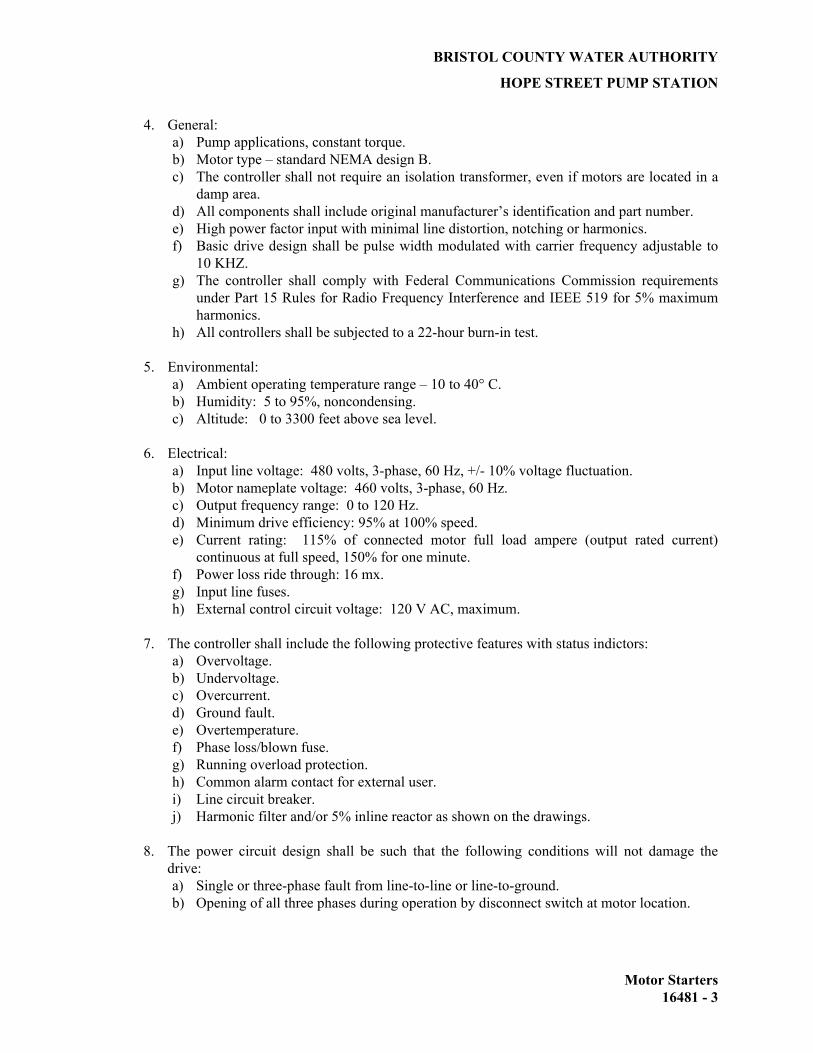
BRISTOL COUNTY WATER AUTHORITY
HOPE STREET PUMP STATION
Motor Starters 16481 - 3
4. General: a) Pump applications, constant torque. b) Motor type – standard NEMA design B. c) The controller shall not require an isolation transformer, even if motors are located in a
damp area. d) All components shall include original manufacturer’s identification and part number. e) High power factor input with minimal line distortion, notching or harmonics. f) Basic drive design shall be pulse width modulated with carrier frequency adjustable to
10 KHZ. g) The controller shall comply with Federal Communications Commission requirements
under Part 15 Rules for Radio Frequency Interference and IEEE 519 for 5% maximum harmonics.
h) All controllers shall be subjected to a 22-hour burn-in test.
5. Environmental: a) Ambient operating temperature range – 10 to 40° C. b) Humidity: 5 to 95%, noncondensing. c) Altitude: 0 to 3300 feet above sea level.
6. Electrical: a) Input line voltage: 480 volts, 3-phase, 60 Hz, +/- 10% voltage fluctuation. b) Motor nameplate voltage: 460 volts, 3-phase, 60 Hz. c) Output frequency range: 0 to 120 Hz. d) Minimum drive efficiency: 95% at 100% speed. e) Current rating: 115% of connected motor full load ampere (output rated current)
continuous at full speed, 150% for one minute. f) Power loss ride through: 16 mx. g) Input line fuses. h) External control circuit voltage: 120 V AC, maximum.
7. The controller shall include the following protective features with status indictors: a) Overvoltage. b) Undervoltage. c) Overcurrent. d) Ground fault. e) Overtemperature. f) Phase loss/blown fuse. g) Running overload protection. h) Common alarm contact for external user. i) Line circuit breaker. j) Harmonic filter and/or 5% inline reactor as shown on the drawings.
8. The power circuit design shall be such that the following conditions will not damage the drive: a) Single or three-phase fault from line-to-line or line-to-ground. b) Opening of all three phases during operation by disconnect switch at motor location.

BRISTOL COUNTY WATER AUTHORITY
HOPE STREET PUMP STATION
Motor Starters 16481 - 4
9. Indicator light safety feature shall indicate when DC bus is energized and capacitors are charged.
10. Internal calibration adjustments:
a) Minimum speed. b) Maximum speed. c) DC boost. d) Acceleration/deceleration rates. e) Stop mode (ramp or coast). f) Automatic restart after fault trip with lockout after five attempts to restart. g) Anti-windmilling adjustable brake time. h) Adjustable volts/Hertz.
11. Unit mounted operator controls: a) Hand-Off-Auto switch. b) Speed adjust potentiometer. c) Indicating speed meter. d) Power ON light. e) VFD Bypass Selector Switch (where shown on the one-line diagrams). f) VFD Bypass indicating light (where shown on the on-line diagrams). g) Local – Remote speed selector switch.
12. Provision for remote external controls: a) Two wire ON-OFF control. b) Speed adjust, analog input (4-20 MADC).
13. Harmonic Requirements: a) General: Under normal operating conditions when minimum of one VFD of each set of
pumps are operating, the line harmonics introduced into the power system form the AC VFD controller shall be within the distortion limits as defined in IEEE 519-(1992).
b) Total Harmonic Distortion (THD) voltage shall not exceed 5 percent and THD current shall not exceed 5 percent, when measured at the point of common coupling (PCC).
c) Harmonic filter shall be provided for each VFD as indicated on the drawings. The filters shall be manufactured by TCI, MTE or approved equal.
14. Bypass Starter:
a) Provide NEMA rated bypass magnetic starter for full speed operation of the pump if the VFD fail to operate. Provide soft-start bypass starters for the pumps 100hp or greater.
E. Combination Starters. Provide combination starters consisting of a starter as described above
with thermal magnetic molded case circuit breaker mounted in a common enclosure. Provide external operator handles for the switches or breakers. Design of the handle with an up-down motion and with the down position indicating OFF. Construct the handles to permit locking in the OFF position with up to three padlocks.
F. Enclosures. Starters and drives shall be mounted in the motor control center unless otherwise
shown on the drawings. Units shown as weatherproof (WP) shall be mounted in NEMA Type 4
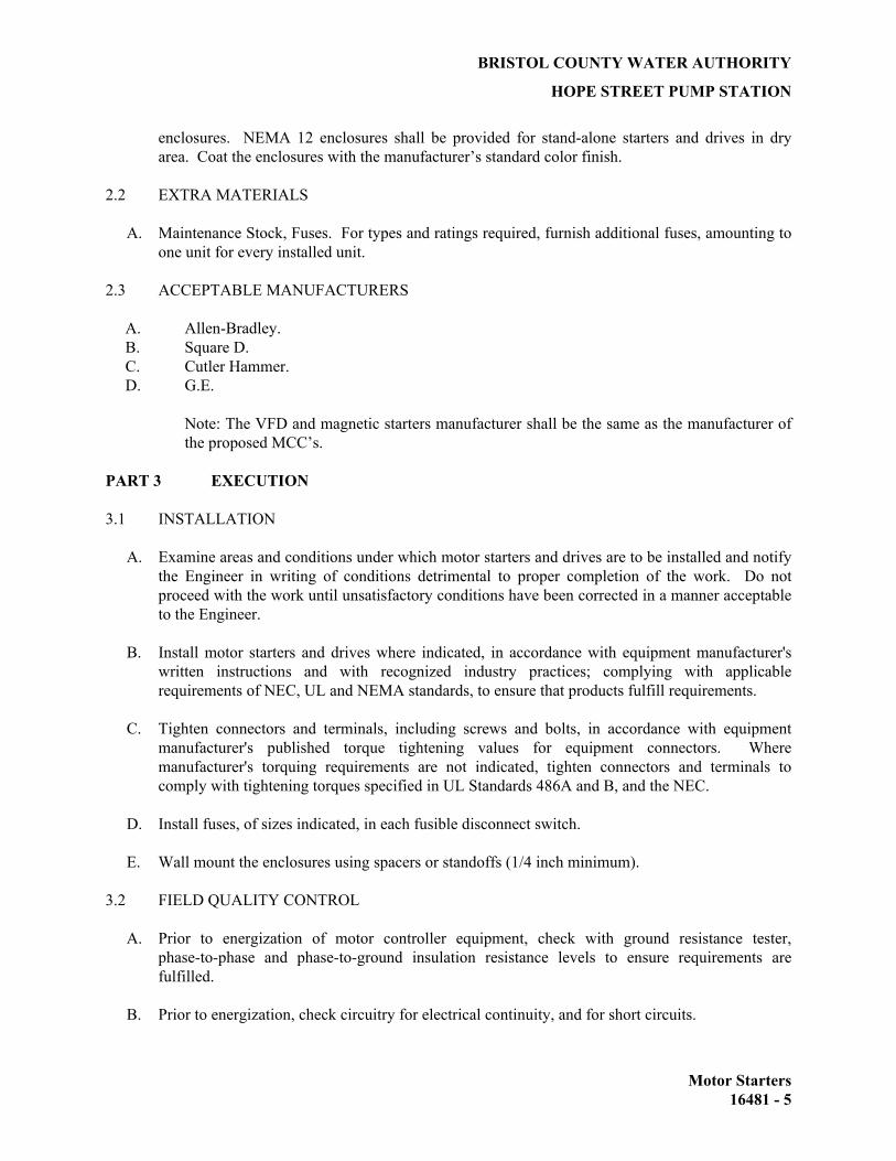
BRISTOL COUNTY WATER AUTHORITY
HOPE STREET PUMP STATION
Motor Starters 16481 - 5
enclosures. NEMA 12 enclosures shall be provided for stand-alone starters and drives in dry area. Coat the enclosures with the manufacturer’s standard color finish.
2.2 EXTRA MATERIALS
A. Maintenance Stock, Fuses. For types and ratings required, furnish additional fuses, amounting to one unit for every installed unit.
2.3 ACCEPTABLE MANUFACTURERS
A. Allen-Bradley. B. Square D. C. Cutler Hammer. D. G.E.
Note: The VFD and magnetic starters manufacturer shall be the same as the manufacturer of the proposed MCC’s.
PART 3 EXECUTION 3.1 INSTALLATION
A. Examine areas and conditions under which motor starters and drives are to be installed and notify the Engineer in writing of conditions detrimental to proper completion of the work. Do not proceed with the work until unsatisfactory conditions have been corrected in a manner acceptable to the Engineer.
B. Install motor starters and drives where indicated, in accordance with equipment manufacturer's written instructions and with recognized industry practices; complying with applicable requirements of NEC, UL and NEMA standards, to ensure that products fulfill requirements.
C. Tighten connectors and terminals, including screws and bolts, in accordance with equipment manufacturer's published torque tightening values for equipment connectors. Where manufacturer's torquing requirements are not indicated, tighten connectors and terminals to comply with tightening torques specified in UL Standards 486A and B, and the NEC.
D. Install fuses, of sizes indicated, in each fusible disconnect switch.
E. Wall mount the enclosures using spacers or standoffs (1/4 inch minimum).
3.2 FIELD QUALITY CONTROL
A. Prior to energization of motor controller equipment, check with ground resistance tester, phase-to-phase and phase-to-ground insulation resistance levels to ensure requirements are fulfilled.
B. Prior to energization, check circuitry for electrical continuity, and for short circuits.

BRISTOL COUNTY WATER AUTHORITY
HOPE STREET PUMP STATION
Motor Starters 16481 - 6
C. Provide the service of the manufacturer’s field engineer for one full day for start-up and operator training.
END OF SECTION

BRISTOL COUNTY WATER AUTHORITY
HOPE STREET PUMP STATION
Automatic Transfer Switch 16490 - 1
SECTION 16490 AUTOMATIC TRANSFER SWITCH PART 1 GENERAL 1.1 SCOPE
A. The Contractor shall provide the labor, tools, equipment, and materials necessary to furnish and install transfer switches in accordance with the plans and as specified herein.
B. Extent of transfer switch work, including to furnish and install control devices, as indicated on the
drawings and as specified herein.
1.2 RELATED DOCUMENTS
A. Drawings and general provisions of the Contract apply to this section. B. Related Sections.
1. Section 16050 Basic electrical 2. Section 16210 Standby Generator
1.3 QUALITY ASSURANCE
A. Reference Standards. 1. National Electrical Code (NEC). 2. Underwriters' Laboratories, Inc. (UL) Compliance UL 1008. Provide transfer switches
and components which are UL listed and labeled and rated for short circuit interrupt and withstand ratings indicated.
3. National Electrical Manufacturers Association (NEMA) Compliance. 4. NEMA Standard Pub/Nos. ICS.
4. NFPA 110 Compliance.
B. Qualifications 1. Firms regularly engaged in manufacture of electrical power transfer switches, of types,
ratings, and capacities required, whose products have been in satisfactory use in similar service for not less than 5 years.
1.4 SUBMITTALS
A. Furnish manufacturer's product data, test reports, and materials certifications as required. B. Submit the following in accordance with conditions of Contract and Division 1 specification
sections: 1. Product Data. Submit manufacturer's data and installation instructions for electrical
power transfer switches.

BRISTOL COUNTY WATER AUTHORITY
HOPE STREET PUMP STATION
Automatic Transfer Switch 16490 - 2
2. Shop Drawings. Submit layout drawings of transfer switches showing accurately scaled equipment locations and spatial relationships to associated electrical equipment in proximity.
3. Wiring Diagrams. Submit elementary control or ladder wiring diagrams for transfer switches, and associated control devices showing connections to prime and alternate power sources, electrical load, and equipment components. Differentiate between portions of wiring that are manufacturer installed and portions that are field installed.
PART 2 PRODUCTS 2.1 MATERIALS
A. Provide factory fabricated, automatic transfer switch, delayed transition type and auxiliary equipment of types, sizes, ratings, and electrical characteristic for services as indicated on the drawings. Transfer switch mechanism shall be electrically operated by and mechanically held. Locking shall be accomplished without the use of latching solenoids, toggle mechanisms or gear arrangements. Operation shall be inherently doubled-throw with normal and emergency contacts moving simultaneously. Operating transfer time shall not exceed one-half of a second. The automatic transfer switches over 1,000 amperes shall be 4 pole construction. Where circuit breakers are used, the breakers must be fixed mounted, 100% rated, solid-state trip power circuit breaker.
B. Main switch contacts shall be segmented, and the configuration shall be designed such that fault
currents provide increased main contact pressure. Separate arcing contacts are required and visual inspection and replacement of a main and separate arcing contact, both stationary and movable, shall be possible from the front of the switch without any disassembly of operating linkages or power conductors. Main contacts consisting of adapted devices, such as subassemblies or contractors, not originally designed for transfer switch application are not acceptable.
C. Provide floor mounted 14 gauge welded steel NEMA Type 1, gasketted enclosure in MCC lineup configuration, or mounted inside the MCC as shown on the Drawings. Coat enclosure with manufacturer's standard color acrylic enamel finish over a corrosion resisting primer. All power cables, lugs, and contacts shall be covered to protect the operator should the switch be closed into a dead fault. Minimum interrupting rating shall be 30,000 ampere RMS, SYM. The enclosure physical dimensions shall not exceed those dimensions shown on the contract drawings and must fit within the allocated space.
D. The transfer switch shall be equipped with the following accessories:
1. Adjustable time delay to override momentary dips in normal source, 0-10 seconds. 2. Full phase voltage relay supervision of the normal source (656-70% dropout and 92-95%
pickup) with at least one close differential relay (83-85% dropout and 92-95% pickup) to detect “brownout” conditions.
3. Voltage/frequency lockout relay (90% pickup, nominal) to prevent premature transfer to emergency source.
4. System test switch, momentary type. 5. Gold plated engine starting control contacts for 2-wire control.

BRISTOL COUNTY WATER AUTHORITY
HOPE STREET PUMP STATION
Automatic Transfer Switch 16490 - 3
6. Auxiliary pilot contacts rated 10 amperes at 120 VAC, two closed on normal and two closed on emergency.
7. Adjustable (2-25 minutes nominal) time delay on retransfer to normal. 8. Adjustable time delay (5 to 15 minutes, nominal) on shutdown of engine-generator after
retransfer of the load to normal. 9. Automatic engine exercisers with load/no load selector switch and 7-day clock with
adjustments for time, day and duration of generator exercise period. 10. Pilot lights mounted on exterior of enclosure doors: Green (normal) and red
(emergency). 11. One N.O. load shed contact on each normal and emergency position. Contacts shall open
3 seconds prior to transfer to either position and shall close 3 seconds after switch has been transferred.
2.2 ACCEPTABLE MANUFACTURERS
A. ASCO (series 7000) B. Russelectric Inc.
PART 3 EXECUTION 3.1 INSTALLATION
A. Install transfer switch, including associated control devices as indicated, in accordance with equipment manufacturer's written instructions, and with recognized industry practices, to ensure that transfer switch comply with requirements. Comply with applicable requirements of NEC and NFPA pertaining to wiring practices and installation of transfer switch.
B. Provide and install housekeeping pads for all floor mounted transfer switches. C. Tighten electrical connectors and terminals, including screws and bolts, in accordance with
equipment manufacturer's published torque tightening values for equipment connectors. Where manufacturer's torquing requirements are not indicated, tighten connectors and terminals to comply with tightening torques specified in UL Standards 486A and 486B.
3.2 GROUNDING
A. Provide equipment grounding connections for transfer switch units as indicated. Tighten connectors to comply with tightening torques specified in UL Standard 486A to assure permanent and effective grounding.
3.3 FIELD QUALITY CONTROL
A. Test transfer switch, by means of simulated power outage; automatic start-up by remote automatic starting, transfer of load and automatic shutdown. Prior to these tests, adjust transfer switch timers for proper system coordination.

BRISTOL COUNTY WATER AUTHORITY
HOPE STREET PUMP STATION
Automatic Transfer Switch 16490 - 4
3.4 TRAINING
A. Train Owner's personnel in procedures for starting up, testing, and operating transfer switches and auxiliary equipment.
END OF SECTION

BRISTOL COUNTY WATER AUTHORITY
HOPE STREET PUMP STATION
APPENDIX A
HOPE STREET PUMP STATION SCADA OPERATION
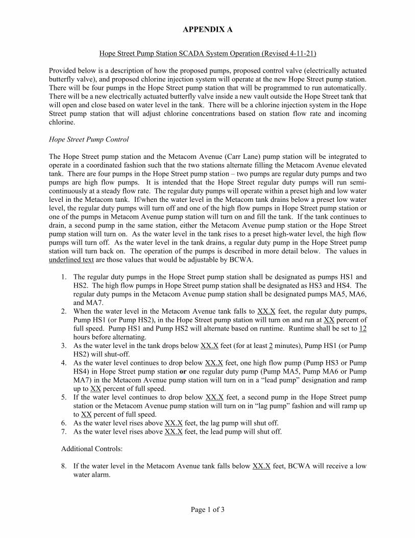
APPENDIX A
Page 1 of 3
Hope Street Pump Station SCADA System Operation (Revised 4-11-21) Provided below is a description of how the proposed pumps, proposed control valve (electrically actuated butterfly valve), and proposed chlorine injection system will operate at the new Hope Street pump station. There will be four pumps in the Hope Street pump station that will be programmed to run automatically. There will be a new electrically actuated butterfly valve inside a new vault outside the Hope Street tank that will open and close based on water level in the tank. There will be a chlorine injection system in the Hope Street pump station that will adjust chlorine concentrations based on station flow rate and incoming chlorine. Hope Street Pump Control The Hope Street pump station and the Metacom Avenue (Carr Lane) pump station will be integrated to operate in a coordinated fashion such that the two stations alternate filling the Metacom Avenue elevated tank. There are four pumps in the Hope Street pump station – two pumps are regular duty pumps and two pumps are high flow pumps. It is intended that the Hope Street regular duty pumps will run semi-continuously at a steady flow rate. The regular duty pumps will operate within a preset high and low water level in the Metacom tank. If/when the water level in the Metacom tank drains below a preset low water level, the regular duty pumps will turn off and one of the high flow pumps in Hope Street pump station or one of the pumps in Metacom Avenue pump station will turn on and fill the tank. If the tank continues to drain, a second pump in the same station, either the Metacom Avenue pump station or the Hope Street pump station will turn on. As the water level in the tank rises to a preset high-water level, the high flow pumps will turn off. As the water level in the tank drains, a regular duty pump in the Hope Street pump station will turn back on. The operation of the pumps is described in more detail below. The values in underlined text are those values that would be adjustable by BCWA.
1. The regular duty pumps in the Hope Street pump station shall be designated as pumps HS1 and HS2. The high flow pumps in Hope Street pump station shall be designated as HS3 and HS4. The regular duty pumps in the Metacom Avenue pump station shall be designated pumps MA5, MA6, and MA7.
2. When the water level in the Metacom Avenue tank falls to XX.X feet, the regular duty pumps, Pump HS1 (or Pump HS2), in the Hope Street pump station will turn on and run at XX percent of full speed. Pump HS1 and Pump HS2 will alternate based on runtime. Runtime shall be set to 12 hours before alternating.
3. As the water level in the tank drops below XX.X feet (for at least 2 minutes), Pump HS1 (or Pump HS2) will shut-off.
4. As the water level continues to drop below XX.X feet, one high flow pump (Pump HS3 or Pump HS4) in Hope Street pump station or one regular duty pump (Pump MA5, Pump MA6 or Pump MA7) in the Metacom Avenue pump station will turn on in a “lead pump” designation and ramp up to XX percent of full speed.
5. If the water level continues to drop below XX.X feet, a second pump in the Hope Street pump station or the Metacom Avenue pump station will turn on in “lag pump” fashion and will ramp up to XX percent of full speed.
6. As the water level rises above XX.X feet, the lag pump will shut off. 7. As the water level rises above XX.X feet, the lead pump will shut off.
Additional Controls:
8. If the water level in the Metacom Avenue tank falls below XX.X feet, BCWA will receive a low
water alarm.

APPENDIX A
Page 2 of 3
9. If the water level in the Metacom Avenue tank rises above XX.X feet, BCWA will receive a high water alarm.
10. The high flow pumps in the Hope Street pump station and the regular duty pumps in the Metacom Avenue pump station shall be programmed to alternate their lead/lag functionality. When a pump in Hope Street pump station is performing lead pump duty, a second pump in the Hope Street pump station shall perform lag pump duty. When a Metacom Avenue pump is lead duty, a second pump in Metacom will be lag duty. The stations will alternate based on fill cycles. The pumps shall alternate lead/lag for each tank filling cycle, as described below:
a. Cycle 1 – HS3 is lead pump, HS4 is lag pump. b. Cycle 2 – MA5 is lead pump, MA6 is lag pump. c. Cycle 3 – HS4 is lead pump, HS3 is lag pump. d. Cycle 4 – MA6 is lead pump, MA7 is lag pump. e. Cycle 5 – HS3 is lead pump, HS4 is lag pump. f. Cycle 6 – MA7 is lead pump, MA5 is lag pump. g. Cycle 7 – HS4 is lead pump, HS3 is lag pump. h. Cycle 8 – MA5 is lead pump, MA6 is lag pump. i. Cycle 9 – HS3 is lead pump, HS4 is lag pump. j. Cycle 10 – MA6 is lead pump, MA7 is lag pump. k. Cycle 11 – HS4 is lead pump, HS3 is lag pump. l. Cycle 12 – MA7 is lead pump, MA5 is lag pump.
11. If the water level in the Metacom Avenue tank falls below the low-low water level (XX.X feet)
after the lead and lag pump have both been signaled to turn on, the lead pump in the alternate station will turn on.
12. If the pressure on the discharge side of the Hope Street pump station falls below XX.X psi, BCWA will receive a low pressure alarm.
13. If the pressure on the discharge side of the Hope Street pump station rises above XX.X psi, BCWA will receive a high pressure alarm.
14. If the pressure on the suction side of the Hope Street pump station falls below XX.X psi, BCWA will receive a low pressure alarm. If any pump in the station is running at the time this alarm is activated, those pumps will turn off.
15. If any pump fails to run, BCWA will receive a pump fail to run alarm. Chlorine Injection at Hope Street Pump Station It is the intent of this specification that sodium hypochlorite will be delivered to the system via two (2) chlorine injection pumps located in the new Hope Street pump station chlorine room. The chlorine injection pump speed will be controlled based on flow in the downstream piping, as measured via electromagnetic meter located in the new pump station building. Within the new pump station there will be ports and lines connected to chlorine analyzers in the new chlorine room – one analyzer for upstream chlorine concentration and one analyzer for downstream chlorine concentration. The chlorine analyzers will serve to adjust the speed of the chlorine dosing pumps, verify the estimated chlorine concentration, and as a fail/stop measure in the event that chlorine concentrations exceed a preset concentration. Under normal conditions, it is anticipated that chlorine dosing will be based solely on the electromagnetic flow meter signal.
1. The discharge chlorine concentration leaving the pump station shall be XX ppm. 2. The chlorine injection pump speed shall be adjusted based on station flow and targeted chlorine
dose (i.e., desired chlorine concentration – upstream chlorine concentration), as measured by the upstream chlorine analyzer.
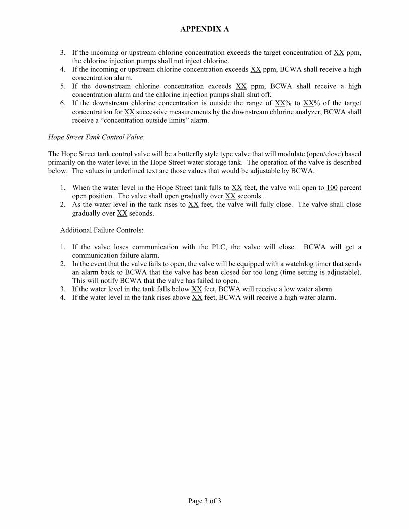
APPENDIX A
Page 3 of 3
3. If the incoming or upstream chlorine concentration exceeds the target concentration of XX ppm, the chlorine injection pumps shall not inject chlorine.
4. If the incoming or upstream chlorine concentration exceeds XX ppm, BCWA shall receive a high concentration alarm.
5. If the downstream chlorine concentration exceeds XX ppm, BCWA shall receive a high concentration alarm and the chlorine injection pumps shall shut off.
6. If the downstream chlorine concentration is outside the range of XX% to XX% of the target concentration for XX successive measurements by the downstream chlorine analyzer, BCWA shall receive a “concentration outside limits” alarm.
Hope Street Tank Control Valve The Hope Street tank control valve will be a butterfly style type valve that will modulate (open/close) based primarily on the water level in the Hope Street water storage tank. The operation of the valve is described below. The values in underlined text are those values that would be adjustable by BCWA.
1. When the water level in the Hope Street tank falls to XX feet, the valve will open to 100 percent open position. The valve shall open gradually over XX seconds.
2. As the water level in the tank rises to XX feet, the valve will fully close. The valve shall close gradually over XX seconds.
Additional Failure Controls: 1. If the valve loses communication with the PLC, the valve will close. BCWA will get a
communication failure alarm. 2. In the event that the valve fails to open, the valve will be equipped with a watchdog timer that sends
an alarm back to BCWA that the valve has been closed for too long (time setting is adjustable). This will notify BCWA that the valve has failed to open.
3. If the water level in the tank falls below XX feet, BCWA will receive a low water alarm. 4. If the water level in the tank rises above XX feet, BCWA will receive a high water alarm.

BRISTOL COUNTY WATER AUTHORITY
HOPE STREET PUMP STATION
APPENDIX B
PHOTOS – EXISTING DRAIN, OVERFLOW, AND INLET/OUTLET PIPE FOR HOPE
STREET TANK

