project manager software - softdb.com · 5 1 overview the smartsms-net system offers a flexible...
TRANSCRIPT

Project Manager Software smartSMS-NET Sound Masking System
User Guide
Soft dB Inc. 1040, Belvedere Avenue, Suite 215 Quebec (Quebec) Canada G1S 3G3 Toll free: 1-866-686-0993 (USA and Canada) E-mail: [email protected]
V20190702

i
Content
1 Overview .................................................................................................................................. 5
2 Create a Project ....................................................................................................................... 6
3 Edit Project Layout .................................................................................................................. 7
3.1 Import a Background Image .................................................................................................................... 7
3.2 Add smartSMS-NET Controllers .............................................................................................................. 9
3.3 Add Loudspeakers ..................................................................................................................................... 10
3.4 Add Wires ...................................................................................................................................................... 11
3.5 Add Active Volume Control Sensors ................................................................................................... 12
3.6 Add Power-Supply Units ......................................................................................................................... 13
3.7 Add Volume Control Knobs .................................................................................................................... 14
3.8 Add Music and Paging Sources ............................................................................................................. 15
3.9 Create Zones ................................................................................................................................................ 16
3.10 Set Layout Scale .......................................................................................................................................... 17
3.11 Analyze Zone Coverage ........................................................................................................................... 18
3.12 List System Components ......................................................................................................................... 20
3.13 Export Layout Image ................................................................................................................................. 20
4 Link smartSMS-NET Controllers to the Project ................................................................... 21
5 Communicate with the Controllers ...................................................................................... 24
5.1 Communicate using USB ......................................................................................................................... 24
5.2 Communicate using Local Area Network (LAN) .............................................................................. 25
5.2.1 Create a Basic Network .............................................................................................................. 25
6 Set-up System Parameters ................................................................................................... 27
6.1 Enter System Setup ................................................................................................................................... 28
6.2 Adjust the Sound Masking Equalizer .................................................................................................. 29
6.2.1 Calibrate the Sound Masking Equalizer .............................................................................. 30 6.2.2 Manually Adjust the Sound Masking Equalizer ................................................................ 35 6.2.3 Select the Sound Masking Target Spectrum ..................................................................... 36
6.3 Adjust the Sound Masking Volume ..................................................................................................... 37
6.4 Set-Up the Sound Masking Active Volume Control ....................................................................... 38

ii
6.4.1 Select the Active Volume Control Sensor Input ............................................................... 39
6.5 Set-Up the Sound Masking Ramp-Up ................................................................................................. 44
6.5.1 Start the Sound Masking Volume Ramp-Up ...................................................................... 45
6.6 Set-Up Music and Paging (Auxiliary) ................................................................................................... 46
6.6.1 Select the Auxiliary Inputs ....................................................................................................... 46 6.6.2 Adjust the Auxiliary Input Mixer ............................................................................................ 50 6.6.3 Adjust Auxiliary Output Equalizer ......................................................................................... 51 6.6.4 Adjust Auxiliary Output Volume ............................................................................................ 53
6.7 Set-Up Volume Control Knobs .............................................................................................................. 54
6.8 Set-Up the Volume Schedule ................................................................................................................. 55
6.9 Input Type Selection ................................................................................................................................. 56
6.10 Advanced Settings ..................................................................................................................................... 57
6.10.1 LED Indicator ................................................................................................................................. 57 6.10.2 Network Setup ............................................................................................................................. 57 6.10.3 On-Board Clock ............................................................................................................................ 58 6.10.4 LEED Schedule .............................................................................................................................. 59 6.10.5 Power ............................................................................................................................................... 59 6.10.6 Error Log ......................................................................................................................................... 60 6.10.7 Temperature ................................................................................................................................. 60 6.10.8 Reboot SMS ................................................................................................................................... 60 6.10.9 Sound Masking Equalizer Mode ............................................................................................ 61 6.10.10 Speaker Monitoring .................................................................................................................... 61 6.10.11 Reset SMS Configuration .......................................................................................................... 61 6.10.12 Emergency Relay ......................................................................................................................... 61
6.11 Output Channel Overview ...................................................................................................................... 62
6.12 Color Codes in Commissioning Mode ................................................................................................ 63
6.12.1 Controller Icon Color Overlay ................................................................................................. 63 6.12.2 Controller Icon Color Contour ................................................................................................ 63 6.12.3 Speaker Line Color ...................................................................................................................... 63
7 Implement System Monitoring ............................................................................................ 64
7.1 Set-Up Automatic System Diagnosis .................................................................................................. 64
7.2 Set-Up Automatic Active Control History Downloads .................................................................. 65
7.3 Set-Up Reporting ........................................................................................................................................ 65
7.4 Start System Monitoring .......................................................................................................................... 65
8 Lock Project Configuration ................................................................................................... 66
9 Save and Recall a Project File ............................................................................................... 67
9.1 Saving the project file as a *.smsp file ................................................................................................ 67

iii
9.2 Exporting the project file to the master smartSMS-NET controller unit................................. 67
9.3 Recalling a project file .............................................................................................................................. 67
10 Project Info ............................................................................................................................ 68
11 Turn the Project Manager Software in a Control Panel ...................................................... 69
11.1 Change Sound Masking Volume in Operation Mode ................................................................... 70
11.2 Change Sound Masking Bass and Treble in Operation Mode .................................................... 71
11.3 Change Music/Paging Volume in Operation Mode ....................................................................... 72
11.4 Visible Layers................................................................................................................................................ 73
Appendix A smartSMS-NET Project Manager Software Installation .................................... 74
Appendix B smartSMS-NET System Networking .................................................................. 77
A-B.1 Basics of Networking ........................................................................................................ 77
A-B.2 Notes on Wireless Networks ............................................................................................ 78
A-B.3 Notes on Wired Networks ................................................................................................ 78
A-B.4 Notes on IP Addresses ...................................................................................................... 79
A-B.5 Soft dB Pre-Configured Router ........................................................................................ 80
A-B.6 Create a Basic Network .................................................................................................... 80
A-B.7 Create an Extended Network using an Access-Point ...................................................... 82
A-B.8 Connect to an Existing Network ...................................................................................... 84
A-B.9 Configure a Router with the Default Parameters ............................................................ 86
A-B.10 Configure an Access-Point ............................................................................................... 89
A-B.11 Use Ethernet Switches ..................................................................................................... 91
Appendix C Perform Sound Level Measurements ............................................................... 92
A-C.1 Using the SLM Utility ........................................................................................................ 92
A-C.2 Performing an Overall Measurement .............................................................................. 93
A-C.3 Performing a Live Measurement ..................................................................................... 94
A-C.4 Spectrum Types ................................................................................................................ 95
A-C.5 Overall Measurement Data Types ................................................................................... 95
Appendix D Set-Up the Calibration Microphone .................................................................. 96
A-D.1 Using a Mezzo Precision Microphone ............................................................................. 96
A-D.2 Using a Piccolo-II Sound Level Meter .............................................................................. 97
A-D.3 Using an iMic Microphone (Discontinued) ...................................................................... 98

iv
Appendix E Reset a smartSMS-NET Controller Unit to Factory Defaults ............................. 99
Appendix F Change a smartSMS-NET Controller Network Setup ...................................... 100
A-F.1 Using a Static IP instead of a dynamic IP ....................................................................... 101
Appendix G Generating a Project Report for Crestron Integrator ..................................... 102
Appendix H Post-Process Active Control History Files ....................................................... 103
Appendix I Evaluating Speech Privacy .............................................................................. 105
A-I.1 Configuring a Noise Source ........................................................................................... 105
A-I.2 Performing a Speech Privacy Test for an Open Office .................................................. 106
A-I.2.1 Measuring the Source Levels.......................................................................... 107 A-I.2.2 Measuring the Receiver Levels ....................................................................... 109 A-I.2.3 Measuring the Background Noise Levels ....................................................... 110 A-I.2.4 Adding Sound Masking .................................................................................. 111 A-I.2.5 Analyzing Results ............................................................................................ 111
A-I.3 Performing a Speech Privacy Test for a Closed Office .................................................. 112
A-I.3.1 Measuring the Source Levels.......................................................................... 113 A-I.3.2 Measuring the Receiver Levels ....................................................................... 115 A-I.3.3 Measuring the Background Noise Levels ....................................................... 116 A-I.3.4 Adding Sound Masking .................................................................................. 117 A-I.3.5 Analyzing Results ............................................................................................ 117

5
1 Overview
The smartSMS-NET system offers a flexible approach allowing to create small installations with only a few zones up to large installations with many zones. This flexibility is offered by the smartSMS-NET controllers which are at the heart of the system.
The smartSMS-NET system offers a wide range of controllers ranging from small low-power 2-channel units to high-power 8-channel units. These controllers can be networked together to create a scalable system appropriate for small to large projects.
The smartSMS-NET Project Manager software is an essential element of the system. It allows to create, manage and operate the smartSMS-NET system. This software is extensively described in this user manual. For more information on the Project Manager Software download and installation, refer to Appendix E, smartSMS-NET Project Manager Software Installation, p.74.
The following sections of this user manual describe in details how to create, manage and operate a smartSMS-NET sound masking system:
1) Create a smartSMS-NET project using the Project Manager software (p. 6) 2) Edit the project layout; import background image, place loudspeakers, place smartSMS-NET
controllers, add wiring, etc. (p. 7) 3) Link the smartSMS-NET controllers to the project (p. 21) 4) Communicate with the smartSMS-NET controllers (p. 24) 5) Set-up system parameters; calibrate sound masking, set-up music and paging, etc. (p. 27) 6) Implement system monitoring (optional) (p. 64) 7) Implement an end-user control panel (p. 66)

6
2 Create a Project
The smartSMS-NET projects are software files integrating the layout and parameters of the system. Hence, the first step in any smartSMS-NET system installation is to create a smartSMS-NET project.
Launch the Project Manager software from the Start Menu.
The Project Manager software contains all the functions to create, edit, commission and operate a smartSMS-NET system.
1) Click on the button to create a new project. This will launch the new project name prompt.
2) Enter the new project name in the text field.
Note: The project name is limited to 24 characters and must not contain certain characters like spaces or slash bars “/”.

7
3 Edit Project Layout
Once a project is created, the project layout needs to be laid down. The layout is the schematic view of the project; it displays the layout of zones, speakers, smartSMS-NET controller units, etc.
3.1 Import a Background Image
It is recommended to import a background image to the layout to make it easier to interpret and use.
1) Click on the button to import background image.
2) Select the appropriate file type from the available image types. 3) Browse for the correct file in the browser window and click “OK”. 4) On the preview window, you can crop the image if needed (click on the first corner and
drag to the second to define the crop frame (red dot line))
5) Click “OK” on the preview window to confirm

8
After these steps, the background image will be loaded in the project and it will be displayed in the layout section of the interface:

9
3.2 Add smartSMS-NET Controllers
Once the background image is imported, you can add smartSMS-NET controllers on the layout. The smartSMS-NET controller is the core of the system.
1) Click on the button to select the “Add Controller” tool.
2) With the “Add Controller” tool selected, click on the layout to add a smartSMS-NET controller at the desired location upon which a prompt will request the following information:
• Controller Name (identifier) • Controller Model
3) Click “OK” to confirm the information
4) The “Add Controller” tool keeps being active so other controllers can be added immediately.
Note: The first controller to be added on the layout must be the Master controller. The Master controller holds the global project configuration. Since every other unit refers to the Master, it’s necessary to add it in the project before adding any other controller. Not all controller models can be a Master: refer to controller specifications for more info.
Note: To change the properties of the controller (name or model), select the controller on the layout
and click on the button.

10
3.3 Add Loudspeakers
Once the smartSMS-NET controllers are added on the layout, you can add loudspeakers to it.
1) Click on the button to add a loudspeaker on the layout.
2) With the “Add Loudspeaker” tool selected, click on the layout to add a loudspeaker at the desired location.
3) The “Add Loudspeaker” tool keeps being active so other loudspeakers can be added immediately.
Note: When loudspeakers are not yet connected with wires, they appear gray. The gray overlay will disappear as soon as they get connected to a smartSMS-NET controller unit with wiring.
Note: Should you want to change the properties of a speaker (type, color, tap, etc.), select the
speaker(s) on the layout and click on the button.
11
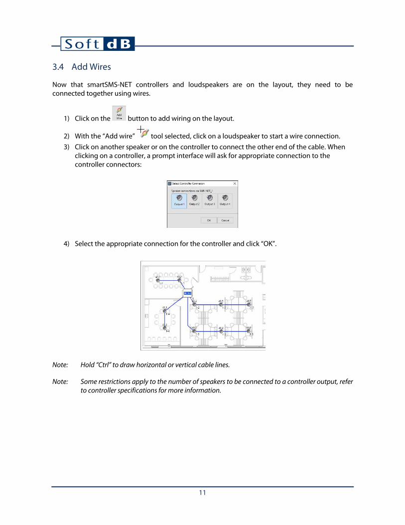
3.4 Add Wires
Now that smartSMS-NET controllers and loudspeakers are on the layout, they need to be connected together using wires.
1) Click on the button to add wiring on the layout.
2) With the “Add wire” tool selected, click on a loudspeaker to start a wire connection. 3) Click on another speaker or on the controller to connect the other end of the cable. When
clicking on a controller, a prompt interface will ask for appropriate connection to the controller connectors:
4) Select the appropriate connection for the controller and click “OK”.
Note: Hold “Ctrl” to draw horizontal or vertical cable lines.
Note: Some restrictions apply to the number of speakers to be connected to a controller output, refer to controller specifications for more information.

12
3.5 Add Active Volume Control Sensors
Active volume control allows adjusting automatically the sound masking volume using noise sensors. When noise activity is high (noisy) the sound masking volume will be higher and when noise activity is low (quiet) the sound masking volume will be lower. Refer to the Active Volume Control Sensors specifications for more information.
1) Click on the button to add an active volume control sensor on the layout.
2) With the “Add sensor” tool selected, click on the layout to add a sensor. 3) Add a wire from the sensor to the smartSMS-NET controller unit.
Upon clicking on the controller to connect the end of the wire, the connection interface will display the available inputs. Note that if some inputs are already connected to a sensor line, they will not be available in the connection interface.
Note: When using a shared input (active/auxi), the connected cable will determine the input type to be used. Refer to section 8.9, Input Type Selection, p. 56 for more info.

13
3.6 Add Power-Supply Units
The smartSMS-NET controllers require a 24V power-supply to work. However, it is not required to include it on the layout but it is a good practice to do so to document the project and help installers.
1) Click on the button to add a power-supply unit on the layout.
2) With the “Add power-supply” tool selected, click on the layout to add a power-supply unit.
3) Add a wire from the power-supply to the smartSMS-NET controller unit.
Note: Should you want to change the properties of a power-supply (type), select the power-supply
on the layout and click on the button.

14
3.7 Add Volume Control Knobs
Wall mounted volume control knobs can be connected to a controller to allow a manual adjustment of the sound masking (and/or music) volume. A volume control knob can only be connected to one controller.
1) Click on the button from the Edition Tab to add a volume control knob on the plan layout.
2) With the “Add knob” tool selected, click on the layout to add a volume control knob. 3) Add a wire from the volume control knob to the controller.

15
3.8 Add Music and Paging Sources
It is possible to play music and make public announcements on the smartSMS-NET system. An auxiliary source can be connected to many controllers. Refer to controller user guide form more information.
1) Click on the button to add a Music/Paging source on the layout.
2) With the “Add Auxi.” tool selected, click on the layout to add a Music/Paging source. 3) Add a wire from the Music/Paging source to the smartSMS-NET unit.
Upon clicking on the controller to connect the end of the wire, the connection interface will display the available inputs. Note that if some inputs are already connected to an audio source, they will not be available in the connection interface.
Note: When using a shared input (active/auxi), a connector may already be used for active control sensor. Hence the corresponding button may be disabled. Also, the connected cable will determine the input type to be used. Refer to section 8.9, Input Type Selection, p. 56 for more info.
Note: Should you want to change the properties of an auxiliary source (music vs paging), select the
auxiliary source(s) on the layout and click on the button.

16
3.9 Create Zones
Zones are areas of similar sound masking environment. Zones can include from one speaker line to several speaker lines from many controllers.
1) Click on the button to add a zone on the layout.
2) With the “Add Zone” tool selected, click on the plan layout to draw the zone contour. 3) Click on the starting point to close the zone.
Note: A speaker line can’t be divided between two zones. In other words, there can’t be one speaker in Zone A and one speaker in Zone B from the same speaker line.
Note: Should you want to change the properties of a zone (name, color, transparency, etc.), select
the zone(s) on the layout and click on the button.
Note: Zones can be grouped or ungrouped using the and the buttons.
Note: Hold “Ctrl” to draw horizontal or vertical zone lines.

17
3.10 Set Layout Scale
It is recommended to set the layout scale in order to use all the features of the Project Manager software. The features requiring appropriate scale definition includes zone area calculation, wire length estimation, measure lines, etc.
1) Click on the button to set the plan scale.
2) With the “Set Scale” tool selected, click on the plan layout to draw a line between two points between which you know the real distance in meters or feet.
3) Enter the real distance between the two points in meters or feet.

18
3.11 Analyze Zone Coverage
A zone can be analyzed for appropriate sound masking coverage. The coverage quality is defined by the distance from each speaker to the other and by the zone acoustical environment. For example, surface speakers must be closer to each other than plenum speakers to avoid getting noticeable “hot-spots”.
1) Select a zone on the layout.
2) Click on the button to open the Zone Properties interface.
3) Click on the button to access the Zone Analysis interface.

19
The top-left controls allow defining the acoustical environment and the bottom-left indicators show the result of the analysis. The image on the right shows the coverage of each loudspeaker.
The “Total Speaker Coverage” should be 100% of the zone area. If the “Speaker Coverage” is less than 100%, the zone image will show white areas meaning insufficient coverage. When this occurs, it’s recommended to increase the speaker density over the zone surface.
The “Average Speaker Coverage” indicates the average area covered by each loudspeaker.

20
3.12 List System Components
Once the layout is finished, the list of components (Bill of Material, or BOM) can be displayed. Click
on the button from the Project toolbar to access the Bill of Material:
Note: Wire quantity is a rough estimate based on the layout scale and layout wire length. A more appropriate estimate of the needed cable length would be to double this quantity.
3.13 Export Layout Image
The layout image can be exported using the button from the Project toolbar. This function exports the image as a *.png file which can be used in a Word document or sent in an email.

21
4 Link smartSMS-NET Controllers to the Project
Subsequent to project edition and before commissioning the system, it is necessary to link real smartSMS-NET controller units to their virtual alias in the software. In order to do so, follow these steps:
1) Connect the smartSMS-NET controller(s) to the computer using a USB cable, Wi-Fi or Ethernet. The connected controllers should appear in the “Available Controllers” list on the lower left corner of the main interface.
2) Click on the button to select the “Link” tool.
3) With the “Link” tool selected, click on a smartSMS-NET controller icon on the layout to identify the target smartSMS-NET controller. This will display a list of detected and available smartSMS-NET controllers that fit the model of the targeted controller on the layout.
• The first controller to be linked must be the Master controller. • The controller model must match the model of the layout controller in order to be
linked. In other words, ML24 types can only be linked to a ML24 layout alias, SL24 with SL24, etc.
4) Select the available controller from the list and click “OK”. This operation will link the physical controller to its alias on the layout.

22
Following this process, the controller should be linked and synchronized with the project and its icon should turn green indicating that the unit is synchronized and updated. Note that the selected unit is not visible anymore in the “Available Controllers” list because it’s now linked to the current project.
Repeat the process until all the controllers are linked:
1
2
3
4

23
Once a controller is linked to the project, any change of parameter made to the virtual controller in the software will be synchronized on the physical controller.

24
5 Communicate with the Controllers
Once the system components are installed on site, a communication network needs to be implemented for the Project Manager software to communicate with the smartSMS-NET controllers. This communication network can be temporary for simple system commissioning or permanent for system requiring an end-user control panel.
The smartSMS-NET controllers can be connected to the Project Manager software using one of the available communication interfaces:
• USB • Local Area Network (LAN) using Wi-Fi (wireless) or Ethernet (wired)
All these communication interfaces can be used transparently on the same project meaning that smartSMS-NET controllers can be connected using USB, Wi-Fi or Ethernet without limitation.
Note that communication is required to change system parameters but is not required for normal operation unless an end-user control panel or system monitoring is required.
5.1 Communicate using USB
The smartSMS-NET controllers can be connected using the USB port. Many smartSMS-NET units can be connected at the same time using available ports on the computer or through a USB hub.
Although this structure is very easy to implement, USB communication is not recommended for permanent communication for which Wi-Fi or wired networks are recommended.
Computer with Project Manager Software smartSMS-NET controllers
USB Hub

25
5.2 Communicate using Local Area Network (LAN)
The smartSMS-NET controllers are all equipped with a networking interface allowing them to access a Local Area Network (LAN). They offer an Ethernet (cabled) interface and a Wi-Fi interface (wireless).
It is required to use a router to establish the network through which the smartSMS-NET controllers and the computer (with the Project Manager software) will communicate. The link between the router and each device can be either wireless or wired depending on the available interface on the router, computer and controllers.
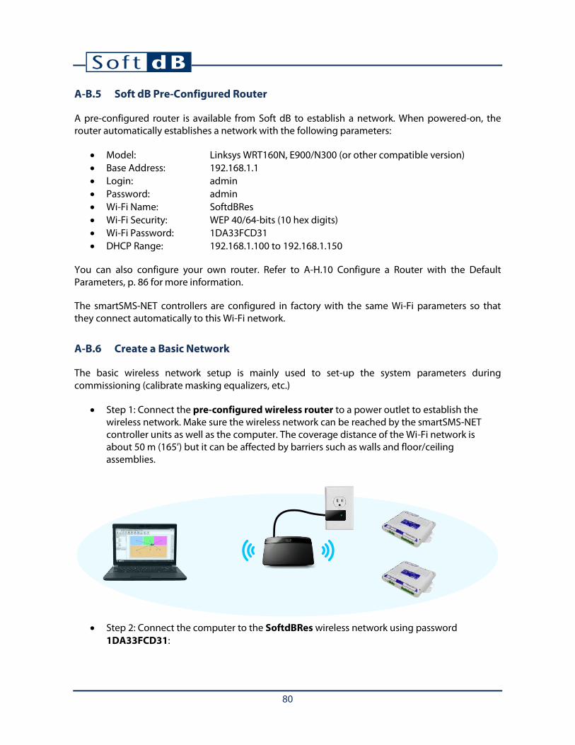
5.2.1 Create a Basic Network
The basic wireless network setup is mainly used to set-up the system parameters during commissioning (calibrate masking equalizers, etc.)
• Step 1: Connect the pre-configured wireless router to a power outlet to establish the wireless network. Make sure the wireless network can be reached by the smartSMS-NET controller units as well as the computer. The coverage distance of the Wi-Fi network is about 50 m (165’) but it can be affected by barriers such as walls and floor/ceiling assemblies.
Note: For a more complex network configuration, refer to Appendix H smartSMS-NET System Networking, p. 77.

26
• Step 2: Connect the computer to the SoftdBRes wireless network using password 1DA33FCD31:
• Step 3: Open the Project Manager software and wait for smartSMS-NET controllers to be detected. It can take a few seconds until the smartSMS-NET controllers show up in the software.
27
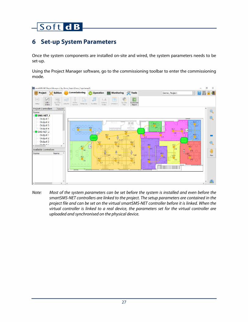
6 Set-up System Parameters
Once the system components are installed on-site and wired, the system parameters needs to be set-up.
Using the Project Manager software, go to the commissioning toolbar to enter the commissioning mode.
Note: Most of the system parameters can be set before the system is installed and even before the smartSMS-NET controllers are linked to the project. The setup parameters are contained in the project file and can be set on the virtual smartSMS-NET controller before it is linked. When the virtual controller is linked to a real device, the parameters set for the virtual controller are uploaded and synchronised on the physical device.

28
6.1 Enter System Setup
Select the zone or the output channel to set-up. Multiple zones and multiple output channels can be selected at the same time to set-up the parameters of the selected items simultaneously.
With a zone or a speaker channel selected, click on the button to enter the setup interface.
The setup interface makes available all parameters at once. Note that some of these parameters are also accessible directly from the commissioning tab as quick-access functions:

29
6.2 Adjust the Sound Masking Equalizer
The sound masking equalizer defines the spectrum shape of the masking sound. This equalizer must be adapted to the acoustical environment to produce an appropriate masking sound. There are two ways to adjust the sound masking equalizer:
The first one is to calibrate the equalizer using a test microphone. This method is recommended as it provides very precise results. Refer to section 8.2.1 Calibrate the Sound Masking Equalizer, p. 30 for more information.
The second one it to manually adjust the equalizer by simply adjusting each equalizer band individually, or by selecting a predefined equalizer. This method is less precise than equalizer calibration and is generally used when it’s not possible to perform an automatic calibration. Refer to section 8.2.2 Manually Adjust the Sound Masking Equalizer, p. 35 for more information.
Click on the button from the Setup Interface to enter the sound masking equalizer setup and access these functions:

30
6.2.1 Calibrate the Sound Masking Equalizer
The sound masking equalizer can be calibrated to fit a target sound spectrum. It is highly recommended to calibrate the sound masking equalizer to increase comfort and effectiveness of the sound masking system. For more information on the target sound spectrum, refer to section 8.2.3 Select the Sound Masking Target Spectrum, p. 36.
To calibrate the sound masking you need to have a calibration microphone. For more information on the calibration microphone, refer to Appendix J, Set-Up the Calibration Microphone, p. 96.
1) Click on the button from the Sound Masking Equalizer Setup to enter the sound masking equalizer calibration interface.

31
2) Click on the button to measure the background noise of the room. The system will be muted to record the background noise (the noise level without the sound masking). This will determine the lowest sound level which can be reached. If the background noise is higher than the target curve, it will be very hard to calibrate the sound masking equalizer appropriately. While the measurement is running, walk slowly in the room to cover most of the zone and avoid speaking or making noise; this measurement requires a quiet environment.
32
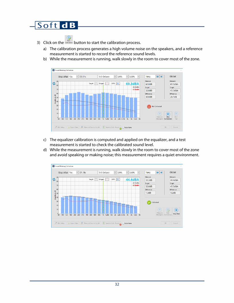
3) Click on the button to start the calibration process. a) The calibration process generates a high volume noise on the speakers, and a reference
measurement is started to record the reference sound levels. b) While the measurement is running, walk slowly in the room to cover most of the zone.
c) The equalizer calibration is computed and applied on the equalizer, and a test measurement is started to check the calibrated sound level.
d) While the measurement is running, walk slowly in the room to cover most of the zone and avoid speaking or making noise; this measurement requires a quiet environment.
33
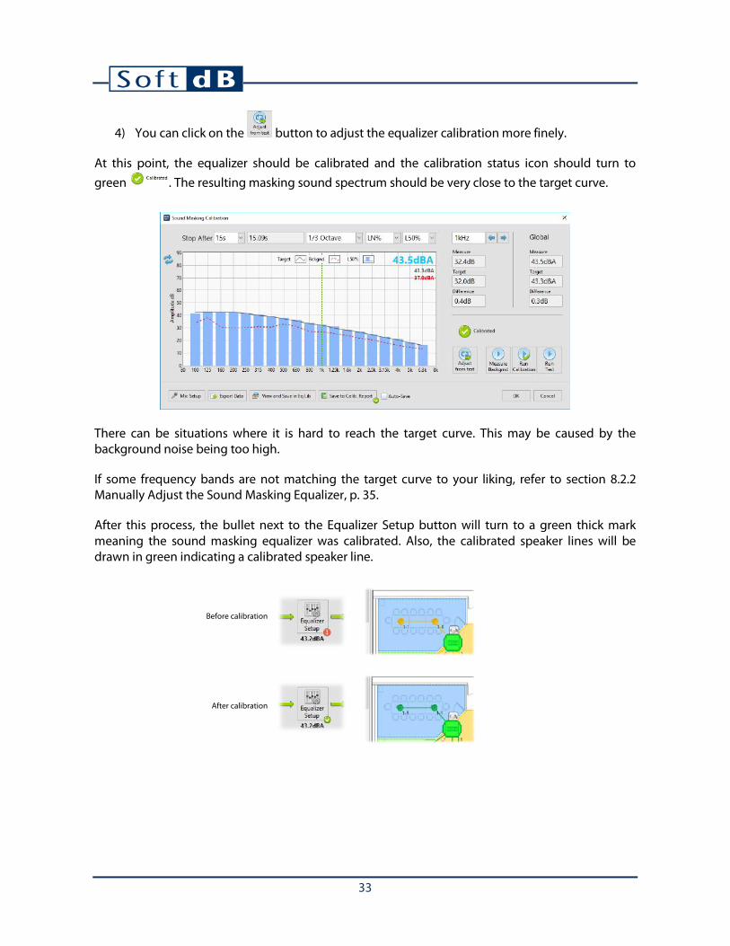
4) You can click on the button to adjust the equalizer calibration more finely.
At this point, the equalizer should be calibrated and the calibration status icon should turn to green . The resulting masking sound spectrum should be very close to the target curve.
There can be situations where it is hard to reach the target curve. This may be caused by the background noise being too high.
If some frequency bands are not matching the target curve to your liking, refer to section 8.2.2 Manually Adjust the Sound Masking Equalizer, p. 35.
After this process, the bullet next to the Equalizer Setup button will turn to a green thick mark meaning the sound masking equalizer was calibrated. Also, the calibrated speaker lines will be drawn in green indicating a calibrated speaker line.
Before calibration
After calibration

34
Calibration Report
Save Measurement Data to Calibration Report
Once the calibration is performed, it is recommended to store the measurement results in a calibration report. Upon performing a final test measurement after the calibration, you can save this resulting spectrum by clicking on the button:
After this operation, the bullet next to the button should turn green indicating that the data was saved. To speed-up the calibration process, the calibration reports can be automatically saved using the “Auto-Save” checkbox.
View Calibration Report
Click on the button from the Commissioning toolbar to view the calibration report for each output channel from the project.

35
6.2.2 Manually Adjust the Sound Masking Equalizer
Even though the automatic calibration is strongly recommended to adjust the sound masking equalizer, there can be situations where it’s not possible to do so. In such cases, the equalizer can be manually adjusted and/or selected from a library of predefined equalizers.
Click on the button to open the “Masking Equalizer” interface.
The top part of the interface shows the current equalizer where each individual band can be adjusted. In addition it displays the associated target spectrum 1 and the “calibrated” status. In the example above, the interface presents the equalizer resulting from an automatic calibration.
The bottom part of the interface shows a library of predefined equalizers. Simply click on an entry to apply the wanted equalizer. This library can also be used to store user-defined equalizers to be recalled later. The equalizer library contains the following equalizers:
• Closed Office 43 dBA (Std Ceiling Tiles) • Open Ceiling 43 dBA • Open Office 43 dBA (Fiberglass Ceiling Tiles) • Open Office 43 dBA (Standard Ceiling Tiles) • Open Office 45 dBA (Fiberglass Ceiling Tiles) • Open Office 45 dBA (Standard Ceiling Tiles)
1 For more information on the target sound spectrum, refer to section 8.2.3 Select the Sound Masking Target Spectrum, p. 48.

36
6.2.3 Select the Sound Masking Target Spectrum
The sound masking target curve is a specific sound spectrum used in the calibration process as a reference. The equalizer is adjusted so the acoustic output of the sound masking system matches the target spectrum.
Click on the button to open the “Target Curves” interface.
The target curve library contains the following spectra:
• Armstrong • Bolt Beranek Newman • Cambridge Sound • Haystack • Lewitz Associates • NRC Optimum (Bradley) • NRC Optimum (CopeCal) • Peutz • Scamp Lencore • Shen Milsom Wilke • Soft dB Mellow • Soft dB Default • Thorburn Associates
Note: The recommended target curve to use is either Soft dB Default or Soft dB Mellow. The later has more bass and less treble than Soft dB Default. Custom curves can also be added to the library.

37
6.3 Adjust the Sound Masking Volume
Once the sound masking spectrum is calibrated according to a specific target curve, there shouldn’t be a need to change the volume. However, if it’s needed you can change the sound masking in the sound masking volume interface:
Click on the button from the Setup Interface to open the “Masking Volume” interface.

38
6.4 Set-Up the Sound Masking Active Volume Control
The active volume control allows increasing or lowering the sound masking volume automatically based on the noise activity measured by active control sensors. When noise activity in a zone is higher, the sound masking level will slowly increase and when the sound activity is lower, the sound masking level will slowly decrease. This feature allows to adjust automatically the sound masking at the optimum level.
Click on the button to open the “Active Control Setup” interface.
To use the active volume control, enable the active control input on the selected output channels from the layout. Then, enter the high and low limits. The high and low limits set the range in which the active control adjusts the volume. The recommended levels are -3dB to +3dB on the calibrated sound masking level.
Hence, if the calibrated sound masking level is 43 dBA, the resulting maximum and minimum will be:
• 46 dBA when noise activity is high (noisy) • 40 dBA when noise activity is low (quiet)
39
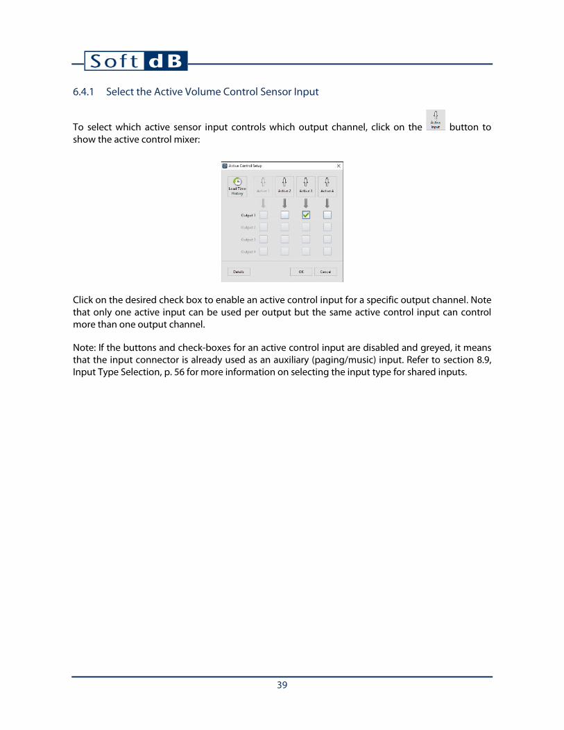
6.4.1 Select the Active Volume Control Sensor Input
To select which active sensor input controls which output channel, click on the button to show the active control mixer:
Click on the desired check box to enable an active control input for a specific output channel. Note that only one active input can be used per output but the same active control input can control more than one output channel.
Note: If the buttons and check-boxes for an active control input are disabled and greyed, it means that the input connector is already used as an auxiliary (paging/music) input. Refer to section 8.9, Input Type Selection, p. 56 for more information on selecting the input type for shared inputs.

40
Adjust the Active Volume Control Sensor Input
Click on the button to enter the active volume control sensor input setup:
The Active Volume Control Input setup interface displays a time history of the sound pressure level (SPL) measured by the sensor. The sound levels should be between 40 dBA (background noise without activity) to 70 dBA (ambient noise with strong activity).
Adjust Input Level
The active control input does not need to be calibrated to work correctly. However, there can be situations where it’s needed to adjust the displayed level in order to give better results, especially when active control historic files are to be downloaded.
Enter the number of sensors in the drop-down menu and click on the button to adjust the displayed level to the ambient sound level.
It is recommended to perform this operation with sound masking ON but without any other ambient noise. In this situation, the ambient sound level should be equal to the target curve level. Hence, the level to enter upon level adjustment should be the target curve level.
In some environments with noise (acoustical or electrical), a “Voice Filter” can be applied on the signal to pick-up frequencies from 200 to 3.5kHz.
You may also adjust the sensitivity directly by clicking on the .

41
~48 dBA
Adjusted Level
Wait for stable level
Enter wanted level
Hit “OK”

42
Adjust Active Control Mode
Click on the button to select from the two available modes:
• Standard (Open Area): This mode should be used when using active volume control to adjust the sound masking volume as a function of the ambient noise activity in an open area.
• Fast (Closed Office Privacy): This mode should be used when using active volume control to adjust the sound masking volume of an adjacent zone from the noise activity of a closed office. Its purpose is to increase the sound masking around a closed office when people are speaking inside the closed office to increase privacy.
It is recommended to use one of these two modes for active control speed. However, the advanced parameters can be modified should one want to fine tune the active control:
The “Up Gain Rate Limit” and “Down Gain Rate Limit” are the maximum volume increase and decrease per analysis period (15s).
The “Sensitivity” along with the “Multiplier” values is used to determine the behavior of the active controller. Low sensitivity values (8 and less) require louder activities in the room to increase the sound masking volume while high sensitivity values will increase the sound masking volume even for a room with a low activity. When set higher than 1, the multiplier allows reaching the high or low limit of the active gain in a shorter time.

43
View Active Control Time History
The smartSMS-NET unit records the sound level time history (activity noise and background noise) on its on-board memory. This data can be downloaded later for further analysis and tuning of the active volume control.
Click on the button to load the active control time history in the post-processing utility. For more information on this utility, refer to Appendix R Post-Process Active Control History Files, p. 103.
The active control time history can also be downloaded automatically to monitor the sound environment of the office. For more information on this feature, refer to section 9.2 Set-Up Automatic Active Control History, p. 65.
Note: The maximum duration of the time history is 7 days.

44
6.5 Set-Up the Sound Masking Ramp-Up
The sound masking ramp-up is a feature allowing to increase slowly the sound masking volume following a system installation. The sound masking advent will be unnoticed if the sound masking volume increases slowly over a period of a few days to a few weeks.
Click on the button to open the “Sound Masking Ramp-Up” interface.
To adjust the ramp-up slope, click on the button.
There is one Ramp-Up counter per smartSMS-NET controller unit and each output channel can be activated on this counter.
45
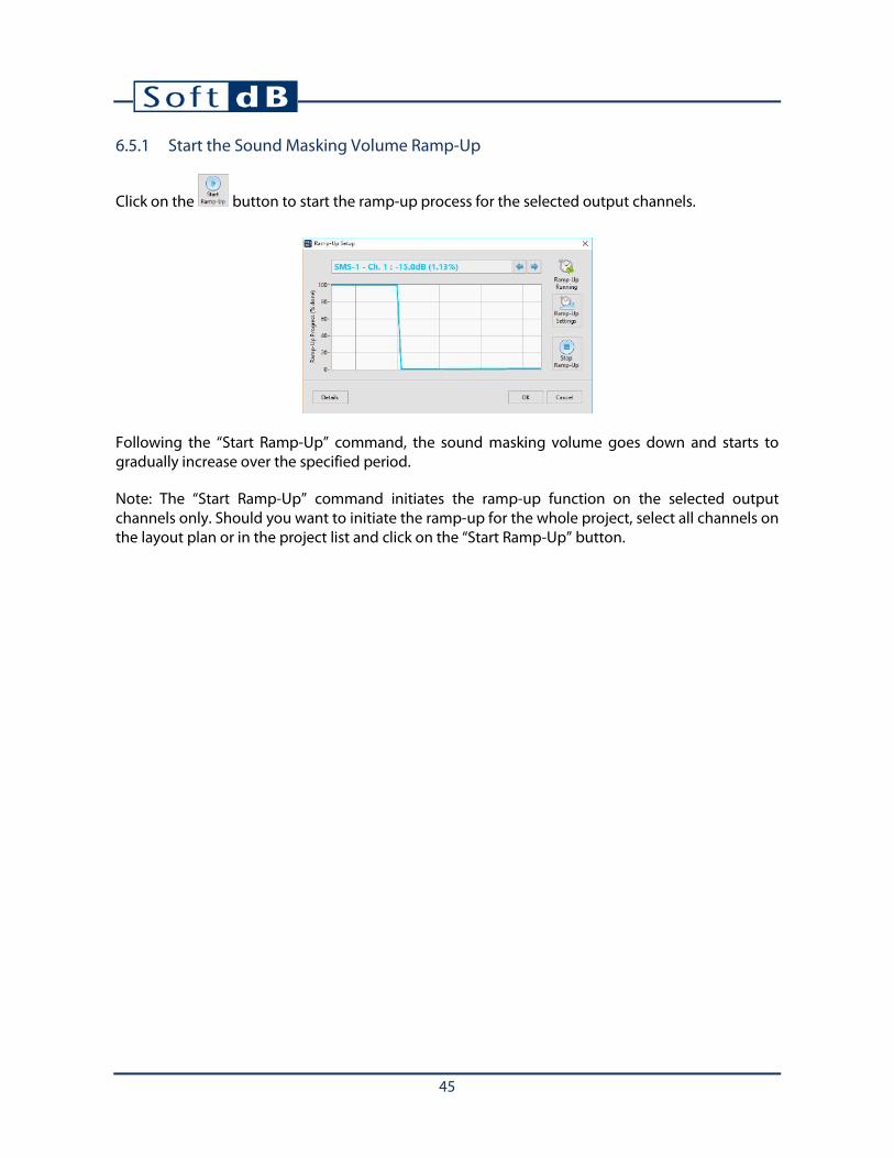
6.5.1 Start the Sound Masking Volume Ramp-Up
Click on the button to start the ramp-up process for the selected output channels.
Following the “Start Ramp-Up” command, the sound masking volume goes down and starts to gradually increase over the specified period.
Note: The “Start Ramp-Up” command initiates the ramp-up function on the selected output channels only. Should you want to initiate the ramp-up for the whole project, select all channels on the layout plan or in the project list and click on the “Start Ramp-Up” button.
46
6.6 Set-Up Music and Paging (Auxiliary)
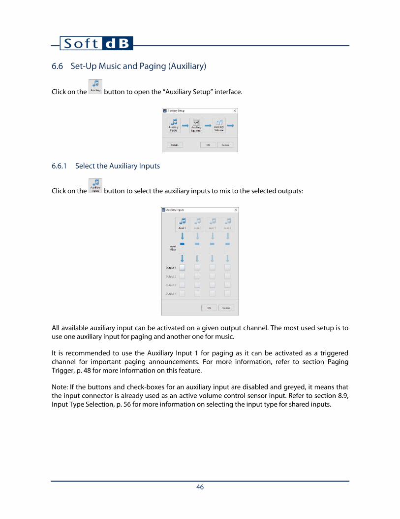
Click on the button to open the “Auxiliary Setup” interface.
6.6.1 Select the Auxiliary Inputs
Click on the button to select the auxiliary inputs to mix to the selected outputs:
All available auxiliary input can be activated on a given output channel. The most used setup is to use one auxiliary input for paging and another one for music.
It is recommended to use the Auxiliary Input 1 for paging as it can be activated as a triggered channel for important paging announcements. For more information, refer to section Paging Trigger, p. 48 for more information on this feature.
Note: If the buttons and check-boxes for an auxiliary input are disabled and greyed, it means that the input connector is already used as an active volume control sensor input. Refer to section 8.9, Input Type Selection, p. 56 for more information on selecting the input type for shared inputs.

47
Auxiliary Input Gain
The first thing to do when using the auxiliary inputs is to adjust the input gain. The following steps explain how to adjust the input gain correctly:
1) Make sure the auxiliary input is appropriately connected to an audio source. Refer to controller user guide for more information.
2) Adjust the volume of the audio source at 75% (if available).
3) Click on the button to access the selected auxiliary input.
4) Check the signal historic. The blue line corresponding to the audio signal amplitude should be between -15 and -25 dB (green area).
5) If the signal is not between -15 and -25 dB, click on to adjust the gain automatically. You can also adjust the gain manually using the “input gain” slider.
6) Following the gain adjustment, the audio signal should be between -15 and -25 dB (green zone). If the signal is still below this range, the source is too low and you must increase the source volume.

48
Paging Trigger
The Paging Trigger is only available when the auxiliary input is configured as a paging input. For more information about the input types, refer to section 8.9, Input Type Selection, p. 56.
Click on the button from the auxiliary input setup to enter the paging trigger setup:
The trigger monitors the audio signal on the auxiliary input and when the audio signal reaches a certain level (meaning that a public announcement is going on), it lowers the sound masking and holds it down until the announcement is over. When the announcement is over, the sound masking volume goes back to normal.
Note: If volume control knobs are installed and set to control the auxiliary input, they are momentarily disabled during the paging to make sure the public announcement is heard.
Priority Call Function
The “Priority Call” function allows to lower the other auxiliary inputs volume while there is a paging announcement on auxiliary input 1. Use the “Att. If Auxi 1 Trigg.” control to set by how many dB you want the current auxiliary input to be attenuated when the Auxiliary input 1 is triggered. This option is available only for auxiliary inputs other than 1.
Trigger activated
Trigger released
Wait for hold-time
Trigger level
Paging Signal
Sound Masking Volume
Public announcement going on
49
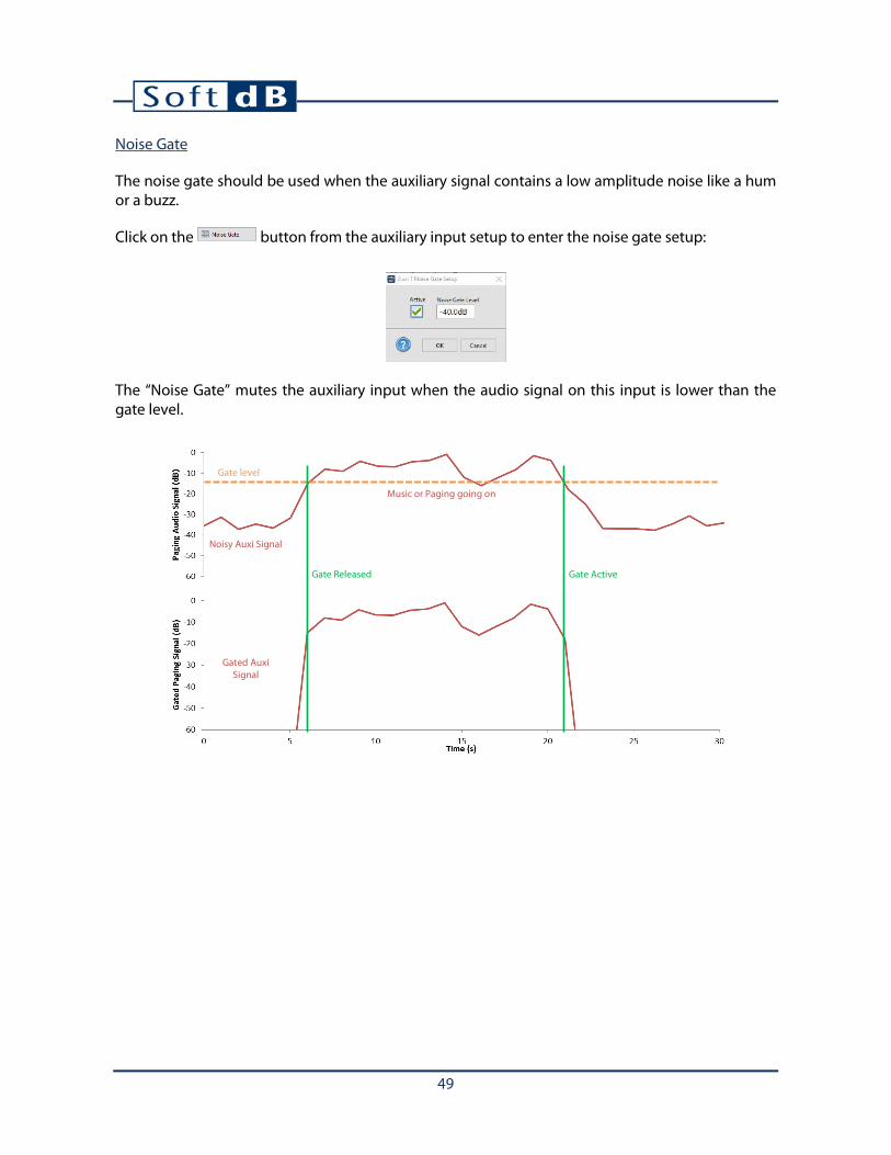
Noise Gate
The noise gate should be used when the auxiliary signal contains a low amplitude noise like a hum or a buzz.
Click on the button from the auxiliary input setup to enter the noise gate setup:
The “Noise Gate” mutes the auxiliary input when the audio signal on this input is lower than the gate level.
Gate Released Gate Active
Gate level
Noisy Auxi Signal
Music or Paging going on
Gated Auxi Signal

50
6.6.2 Adjust the Auxiliary Input Mixer
Once the input gain has been set for each individual input, the respective volume of each auxiliary input can be set using the mixer volume. The mixer volume is used when using multiple auxiliary inputs for music and paging. One could want to adjust the volume of the music input lower than the volume of the paging. Use the vertical cursors to adjust the volume of each input with respect to the other:

51
6.6.3 Adjust Auxiliary Output Equalizer
Once the auxiliary inputs are adjusted (gain and mixer volume), they are fed to the output channel on which an equalizer can be set to enhance the audio quality. Each output channel has its own equalizer.
Click on the button to open the auxiliary equalizer interface:
The top part of the interface shows the current equalizer where each individual band can be adjusted.
The bottom part of the interface shows a library of predefined equalizers. Simply click on an entry to apply the wanted equalizer. This library can also be used to store user-defined equalizers to be recalled later. The equalizer library contains the following equalizers:
• “Flat” (should be used for open ceiling) • “Plenum Space” (should be used for speakers in plenum space to compensate for ceiling tile
transmission loss and up-firing speaker configuration) • “Surface Speaker” (should be used for surface loudspeakers)
52
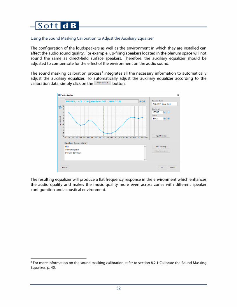
Using the Sound Masking Calibration to Adjust the Auxiliary Equalizer
The configuration of the loudspeakers as well as the environment in which they are installed can affect the audio sound quality. For example, up-firing speakers located in the plenum space will not sound the same as direct-field surface speakers. Therefore, the auxiliary equalizer should be adjusted to compensate for the effect of the environment on the audio sound.
The sound masking calibration process 2 integrates all the necessary information to automatically adjust the auxiliary equalizer. To automatically adjust the auxiliary equalizer according to the calibration data, simply click on the button.
The resulting equalizer will produce a flat frequency response in the environment which enhances the audio quality and makes the music quality more even across zones with different speaker configuration and acoustical environment.
2 For more information on the sound masking calibration, refer to section 8.2.1 Calibrate the Sound Masking Equalizer, p. 40.

53
6.6.4 Adjust Auxiliary Output Volume
The auxiliary volume is applies to the music/paging signal for each output channel.
Click on the button to control the general auxiliary volume.

54
6.7 Set-Up Volume Control Knobs
The smartSMS-NET system provides two volume control knob inputs per controller. This section gives information on the software parameters regarding volume control knobs.
Refer to controller and volume knob user guide for more information on hardware installation and wiring.
Click on the button to open the “Volume Knob Setup” interface.
The volume control knobs can control the volume of sound masking and/or auxiliary (music and paging)
The knob maximum and minimum volumes can be set by clicking on the buttons.
Note: A volume knob can be tested using this interface. Turn the volume knob and the knob image on the software interface should turn at the same position.

55
6.8 Set-Up the Volume Schedule
The volume schedule allows adjusting the volume of the sound masking and/or the music according to certain periods of the day and certain days of the week.
Click on the button to open the “Volume Schedule” interface.
1) Click on the check boxes on the top-left corner to enable the volume schedule for the selected zone(s), SMS unit(s) or speaker(s). The volume schedule can be set for sound masking and/or music.
2) Select the day of the week in the drop-down menu. 3) Click on the graph to select the period to modify, or select the period on the “Period”
numeric field. 4) Click on the “Gain” numeric field or click on the graph to change the calendar gain of the
selected period. 5) Repeat the process for all days of the week.
Note: You can copy a schedule from any day and paste it to another day using the copy/paste buttons.

56
6.9 Input Type Selection
Most smartSMS-NET controller units offer shared input connectors which can act as an active volume control sensor input or an auxiliary (music/paging) input. There are two ways to define the input type for each input connector:
The first way is by drawing a wire to the smartSMS-NET controller on the layout. If a sensor is connected, it will define the input as a sensor input and when an auxiliary source is connected, it will define it as an auxiliary input.
The second way is to manually force it in the input mix interface. Click on the button from the Setup interface to access the input mix interface:
Note: This interface may look different depending on the smartSMS-NET controller model. Some models offer more inputs than other.

57
6.10 Advanced Settings
Click on the button to open the “Advanced Settings” interface
6.10.1 LED Indicator
The lighting mode of the LED indicator on the smartSMS-NET controller unit can be changed to the following:
• Always OFF • Always ON • Flash when connected
6.10.2 Network Setup
The Network setup allows to set-up the Network name (SSID), Security type, and password used by the controller to connect to the wireless network. You can also set a static IP when using Ethernet. This utility requires the controller to be connected, it can’t be used offline.

58
Testing Wireless Communication
You can test the wireless communication of a unit by clicking on the button. The test will send data packets over WiFi and will evaluate the connection quality. The connection transfer speed should be over 200 kbps (over 400kbps is excellent). You can also perform this test on USB to troubleshoot a wireless connection.
6.10.3 On-Board Clock
The smartSMS-NET on-board clock is used for the volume schedule (section 8.8 Set-Up the Volume Schedule, p. 55) and the LEED schedule (section8.10.6, LEED Schedule, p. 59).
This interface allows adjusting the time and time zone used by the smartSMS-NET controller unit on-board clock.
Click on the button to adjust the time and time zone to the time parameters of the computer.
Note: Make sure the time and time zone used on your computer are valid: they will be used to set the time and time zone on the smartSMS-NET controller.

59
6.10.4 LEED Schedule
The LEED schedule allows to put the smartSMS-NET unit in low-power mode on a schedule basis.
If the unit is to be working normally from 6:00 to 22:00, set the start time to 6:00 and the stop time to 22:00.
6.10.5 Power
This interface allows to view the current power drawn from the power-supply. This can be useful when troubleshooting power demanding installations.
Note: Only the RL96-8ch is equipped with current monitoring.

60
6.10.6 Error Log
This interface allows to view the error log on a controller. This can be useful when troubleshooting.
6.10.7 Temperature
This interface allows to view the current temperature and also to see the temperature history (24h, 30 days = 720 values).
Note: On some older controller models with optional on-board clock may not be equipped with temperature monitoring.
6.10.8 Reboot SMS
This function allows to reboot remotely a smartSMS-NET controller unit.
61
6.10.9 Sound Masking Equalizer Mode
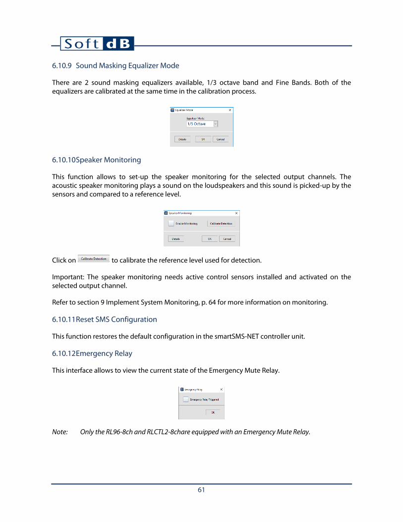
There are 2 sound masking equalizers available, 1/3 octave band and Fine Bands. Both of the equalizers are calibrated at the same time in the calibration process.
6.10.10 Speaker Monitoring
This function allows to set-up the speaker monitoring for the selected output channels. The acoustic speaker monitoring plays a sound on the loudspeakers and this sound is picked-up by the sensors and compared to a reference level.
Click on to calibrate the reference level used for detection.
Important: The speaker monitoring needs active control sensors installed and activated on the selected output channel.
Refer to section 9 Implement System Monitoring, p. 64 for more information on monitoring.
6.10.11 Reset SMS Configuration
This function restores the default configuration in the smartSMS-NET controller unit.
6.10.12 Emergency Relay
This interface allows to view the current state of the Emergency Mute Relay.
Note: Only the RL96-8ch and RLCTL2-8chare equipped with an Emergency Mute Relay.

62
6.11 Output Channel Overview
The Setup Interface offers an output channel overview to see all the current setting values for a specific output channel. Additionally, it displays the available “headroom”. The headroom shows how many decibels are still available before the output saturates.
When the headroom is higher than 3 dB, there is no warning. When the headroom is below 3 dB, a warning is displayed meaning the output is close to saturation. When the headroom is 0 or less, a critical warning is displayed meaning that saturation will occur.
• No Warning: the output level is OK, no action is required. • Warning: The output level can be close to the maximum limit; review the parameters to
identify the cause. • Critical Warning: The output can exceed the maximum limit; review the parameters to
identify the cause.
When a warning or a critical warning is detected, click on the button to open the output channel overview interface:
No Warning Warning Critical Warning

63
6.12 Color Codes in Commissioning Mode
6.12.1 Controller Icon Color Overlay
The color overlay of the smartSMS-NET unit indicates the connection status. The smartSMS-NET unit can be connected using USB or Wi-Fi. The table below shows the color overlay code of the smartSMS-NET icon on the layout and its symbol in the project list.
Color Overlay Linked to the project Connected
(USB or Wi-Fi)
Gray NO -
Green YES YES
Yellow YES NO
If the color overlay is gray, it means that the unit was not linked to a real smartSMS-NET unit. Refer to section 5, Link smartSMS-NET Controller, p. 21, for more information on linking smartSMS-NET units.
6.12.2 Controller Icon Color Contour
The color contour of the smartSMS-NET unit indicates the updated status.
The parameters of the smartSMS-NET unit can be changed either online or offline. If the unit is online (connected) while making those changes, the unit will be updated automatically. However, if the changes are made while the unit is offline (not connected), the changes will not be updated on the physical unit until it is online again. The status of the unit will be “not updated” until that moment.
The table below shows the color contour code of the smartSMS-NET icon on the layout and its symbol in the project list.
Color Contour Updated
Green YES
Yellow NO
6.12.3 Speaker Line Color
In commissioning mode, the speaker lines are colored to indicate their calibration status. The calibration status refers to the sound masking equalizer calibration status. Refer to section XXX for more information on sound masking equalizer calibration.
Color Calibrated
Green YES
Yellow NO

64
7 Implement System Monitoring
Once the system is installed and calibrated, it is possible to implement monitoring. The system monitoring feature performs periodic system diagnosis and active control history reporting.
Note: The monitoring feature requires a computer to communicate with the smartSMS-NET controller units.
7.1 Set-Up Automatic System Diagnosis
The system diagnosis process allows to perform a complete diagnosis of the system periodically.
Click on the button to set-up the system diagnosis parameters.
Reports can be sent at each diagnosis period or only if an error or warning was detected during the system diagnosis.
To be sure the periodic system diagnosis is working it can send an “OK” report periodically.

65
7.2 Set-Up Automatic Active Control History Downloads
The automatic active control history reporting allows to download the history of the sound levels measured by the active volume control sensors. The history files can be opened using the Active Control History Post-Processing Tool (refer to Appendix R, Post-Process Active Control History Files, p. 103). The sound level history provides useful information on the acoustical environment of the office.
Click on the button to set-up the active control reporting parameters.
7.3 Set-Up Reporting
The Project Manager software allows to store the reports locally on the computer and/or send them by email.
Click on the button to set-up the reporting.
7.4 Start System Monitoring
The system monitoring is a process which runs in the Operation mode. The Operation mode is a simpler interface of the Project Manager for the end-user. For more information on the Operation mode, refer to section 13, Turn the Project Manager Software in a Control Panel, p. 69.
Click on the button to start the system monitoring. This operation will lock the interface in Operation mode and start the system monitoring process.

66
8 Lock Project Configuration
When a project is completed, it can be locked to avoid any unwanted modifications. To do so, click
on the button from the “Project” tab. This will block access to the “Edition”, “Commissioning” and “Monitoring” tabs when this project is opened. Upon locking a project, a password can be added to increase the security level.
Should you want to unlock the project, click on the from the “Project” tab. If a password was added, it will be asked.
Note: Contact Soft dB at [email protected] if you forget the password.

67
9 Save and Recall a Project File
9.1 Saving the project file as a *.smsp file
At many points in the process, whether it’s during layout edition or system commissioning, you can
save different versions of the project file using the and buttons. This will store the project file as a *.smsp file. There is no relation between the internal project name and the *.smsp file name; you can name the file with any name and the internal project name will remain the same.
It’s recommended to save multiple versions of the project file along the process to create backup files.
9.2 Exporting the project file to the master smartSMS-NET controller unit
A copy of the project file can be stored in the master smartSMS-NET controller unit internal memory. This feature is designed to keep a copy of the project file along with the physical system to avoid losing it.
To export the project file on the Master controller unit, click on the button from the project toolbar.
9.3 Recalling a project file
A project file can be recalled to restore a system to a known state. For instance at the end of commissioning, it’s highly recommended to save a copy of the project file, either by saving a *.smsp file and/or by exporting it on the master unit. That way, should the client experience any problem with the system, this reference copy can be used to restore the system to this reference state.
To recall a project file, simply open the project file by clicking on the button to load it from a
*.smsp file or by clicking on the button to load the project from the Master controller. Once the project file is opened, the Project Manager software will synchronise every controller linked to the project.

68
10 Project Info
Click on the button to open the “Project Info” interface:
The available information is:
• Project name: Internal project name that smartSMS-NET controller units relate to. • Info: Any useful information which the user wants to add to a project file. • Creation date: Creation date for the project file. • Last SMS Update: Indicate the date and time of the last smartSMS-NET controller access and
modification. It also indicates which user did the modification (computer name) and which version of the software was used.
This interface also contains a function to create a system report for Crestron integrators. This report includes a layout plan of smartSMS-NET controllers and loudspeakers. Each smartSMS-NET controller is listed in a table along with its physical address (MAC Address). Refer to Appendix Q, Generating a Project Report for Crestron Integrator, p. 102 for a sample report.
69
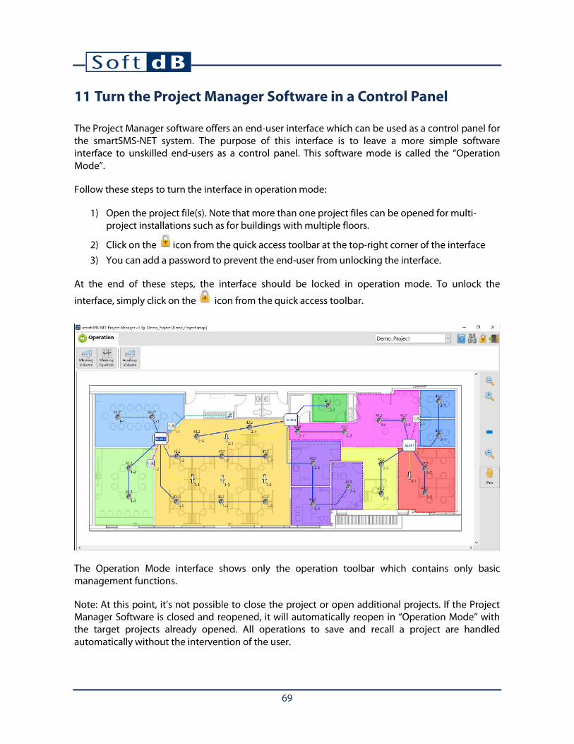
11 Turn the Project Manager Software in a Control Panel
The Project Manager software offers an end-user interface which can be used as a control panel for the smartSMS-NET system. The purpose of this interface is to leave a more simple software interface to unskilled end-users as a control panel. This software mode is called the “Operation Mode”.
Follow these steps to turn the interface in operation mode:
1) Open the project file(s). Note that more than one project files can be opened for multi-project installations such as for buildings with multiple floors.
2) Click on the icon from the quick access toolbar at the top-right corner of the interface 3) You can add a password to prevent the end-user from unlocking the interface.
At the end of these steps, the interface should be locked in operation mode. To unlock the
interface, simply click on the icon from the quick access toolbar.
The Operation Mode interface shows only the operation toolbar which contains only basic management functions.
Note: At this point, it’s not possible to close the project or open additional projects. If the Project Manager Software is closed and reopened, it will automatically reopen in “Operation Mode” with the target projects already opened. All operations to save and recall a project are handled automatically without the intervention of the user.

70
11.1 Change Sound Masking Volume in Operation Mode
This function allows the end-user to change the sound masking volume for a specific zone or group of zones.
1) On the layout select the zone(s), SMS unit(s) or speaker line(s) on which the sound masking volume needs to be changed.
2) Click on the button to open the “Masking Volume” interface. 3) Click on the “Volume” field to enter directly the masking volume or click on the “Mute”
check-box should the sound masking be muted.

71
11.2 Change Sound Masking Bass and Treble in Operation Mode
This function allows the end-user to change the sound masking bass and treble for a specific zone or group of zones.
1) On the office layout select the zone(s), SMS unit(s) or speaker line(s) on which the sound masking equalizer needs to be changed.
2) Click on the button to open the “Masking Eq” interface. 3) Click on the bass and treble fields to change the low frequency and high frequency gain of
the sound masking equalizer.

72
11.3 Change Music/Paging Volume in Operation Mode
This function allows the end-user to change the music and paging volume for a specific zone or group of zones.
1) On the office layout select the zone(s), SMS unit(s) or speaker line(s) on which the auxiliary volume needs to be changed.
2) Click on the button to open the “Auxiliary Volume” interface. 3) Click on the “Absolute Volume” field to enter directly the auxiliary volume or click on the
“Relative Gain” field to enter the gain variation from the current volume. Click on the “Mute” check-box should the music and paging be muted.

73
11.4 Visible Layers
When leaving the system to the end user, it’s a good practice to hide most system components from the layout and only show zones, speakers and masking levels. This way, the end-user only has to select a zone or a speaker to make changes to the system.
Click on the button in the down-right corner of the main interface to open the Layers interface:
Additionally, this interface includes an option for zone selection:
• Border Click – Click on the border of a zone to select it • Inside Click – Click anywhere in the zone to select it
The Mask Level indicates the sound masking level over each loudspeaker. An asterisk next to the label indicates that either active volume control, ramp-up, volume knob or schedule is activated on this channel and may affect the sound masking level.
Note: It’s important to show/hide layers before turning the interface to operation mode because the “layers” button is not accessible in operation mode.
74
Appendix A smartSMS-NET Project Manager Software Installation
Download the software installer using this link: www.softdb.com/software.php?smartsms-net
Double-click on the installer executable to extract the software installer:
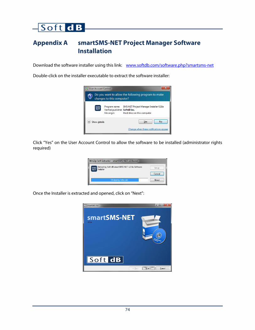
Click “Yes” on the User Account Control to allow the software to be installed (administrator rights required)
Once the Installer is extracted and opened, click on “Next”:

75
Click on “Next” to select the install directory:
Click “Next” to start installation:
Click on “Next” to finish installation

76
After the installation, the drivers are installed:
Click on “Install” to install the drivers (administrator rights required)
Restart the computer to use the software:

77
Appendix B smartSMS-NET System Networking
A-B.1 Basics of Networking
It is required to use a router to establish the network through which the smartSMS-NET controller units and the computer (with the Project Manager software) will communicate. The link between the router and each device can be either wireless or wired depending on the available interface on the router, computer and controllers. The following figures show different configurations using wireless network, wired network or a combination of both. Many configurations are possible; the ones shown below are only a small subset of all possible configurations.
Computer with Project Manager Software
Router
smartSMS-NET controllers

78
A-B.2 Notes on Wireless Networks
To connect to a wireless network, a device needs to know the name of the network, the password and the security encryption type. Hence, the controllers need to know this information to correctly connect to the wireless network. The computer also requires this information when accessing the wireless network:
A-B.3 Notes on Wired Networks
To connect to a wired network, the devices do not have to specify the name and security because they are physically connected. Hence the connection is automatic as soon as a cable is connected from the device to the router.
Hence, to connect a smartSMS-NET controller to a wired network, you just have to connect an Ethernet cable from the smartSMS-NET controller to the router. Note that not all smartSMS-NET controllers are equipped with an Ethernet cable port. Refer to section A-A.3, Controller Connections, p. Error! Bookmark not defined. for more information.
Computer with Project Manager Software
Router
smartSMS-NET controllers
To connect to a wireless network, the devices need to provide the network
name, password and security.

79
A-B.4 Notes on IP Addresses
Once a device is connected to the network (whether on a wired or wireless network) it receives an IP address from the router. The router automatically attributes these IP addresses within a range of address which is typically 192.168.1.100 to 192.168.1.150. The following figure shows an example:
The range used by the router for automatic IP attribution is called the DHCP range. Using the range 192.168.1.100 to 192.168.1.150, up-to 50 devices can be connected at the same time on the network. The range could theoretically be extended up-to 254 devices from 192.168.1.2 to 192.168.1.255. Note that 192.168.1.1 is the IP address of the router itself.
To find the smartSMS-NET controllers on the network, the Project Manager software needs to query each IP address within the DHCP range. Once a smartSMS-NET controller is discovered, it becomes available in the Project Manager software.
Click on the button from the “Tools” toolbar to select the appropriate IP range.
• Default SoftdBRes: Range used by Soft dB pre-configured router (192.168.1.100 to 150) • Automatic: Range guessed from computer IP address • Manual: Range manually entered for specific situations
Computer with Project Manager Software
Router
smartSMS-NET controllers
IP: 192.168.1.114
IP: 192.168.1.106
IP: 192.168.1.127
DHCP Range: 192.168.1.100 to 192.168.1.150
80
A-B.5 Soft dB Pre-Configured Router
A pre-configured router is available from Soft dB to establish a network. When powered-on, the router automatically establishes a network with the following parameters:
• Model: Linksys WRT160N, E900/N300 (or other compatible version) • Base Address: 192.168.1.1 • Login: admin • Password: admin • Wi-Fi Name: SoftdBRes • Wi-Fi Security: WEP 40/64-bits (10 hex digits) • Wi-Fi Password: 1DA33FCD31 • DHCP Range: 192.168.1.100 to 192.168.1.150
You can also configure your own router. Refer to A-H.10 Configure a Router with the Default Parameters, p. 86 for more information.
The smartSMS-NET controllers are configured in factory with the same Wi-Fi parameters so that they connect automatically to this Wi-Fi network.
A-B.6 Create a Basic Network
The basic wireless network setup is mainly used to set-up the system parameters during commissioning (calibrate masking equalizers, etc.)
• Step 1: Connect the pre-configured wireless router to a power outlet to establish the wireless network. Make sure the wireless network can be reached by the smartSMS-NET controller units as well as the computer. The coverage distance of the Wi-Fi network is about 50 m (165’) but it can be affected by barriers such as walls and floor/ceiling assemblies.
• Step 2: Connect the computer to the SoftdBRes wireless network using password
1DA33FCD31:

81
• Step 3: Open the Project Manager software and wait for smartSMS-NET units to be detected. It can take a few seconds until the smartSMS-NET units show up in the software.

82
A-B.7 Create an Extended Network using an Access-Point
This setup is used when some smartSMS-NET units are not in reach of the wireless network from the router. This may be caused by a great distance between the SMS-NET units and the router or by structural barriers such as walls and floor/ceiling assemblies. In this case, it is recommended to use an access-point to extend the wireless network range.
• Step 1: Establish a basic wireless setup (refer to section A-H.7 Create a Basic Network, p. 80) • Step 2: Configure an access-point with a different network name such as SoftdBRes_2. For
more information on how to configure an access-point, refer to A-H.11 Configure an Access-Point, p. 89.
• Step 3: Connect the access-point to the wireless router using a network cable.
• Step 4: Configure the smartSMS-NET controller units to go under the access-point wireless
network with the appropriate network name: a) Connect each smartSMS-NET controller to the computer using a USB cable
Computer with Project Manager Software
Router
Access-Point
Router Access-Point
Connect the Access-Point to one of the Router’s Ethernet ports
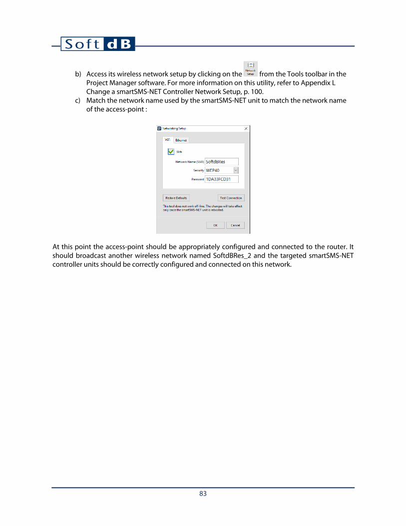
83
b) Access its wireless network setup by clicking on the from the Tools toolbar in the Project Manager software. For more information on this utility, refer to Appendix L Change a smartSMS-NET Controller Network Setup, p. 100.
c) Match the network name used by the smartSMS-NET unit to match the network name of the access-point :
At this point the access-point should be appropriately configured and connected to the router. It should broadcast another wireless network named SoftdBRes_2 and the targeted smartSMS-NET controller units should be correctly configured and connected on this network.

84
A-B.8 Connect to an Existing Network
This setup is used when a permanent network is required for 24/7 access through an existing network.
• Step 1: Contact the IT manager to receive the authorisation to connect wireless access-point(s) to the network.
• Step 2: Ask the IT manager for the parameters to use to configure the access-point(s): • Network Name (SSID), • Security (WEP or WPA personal), • Password.
• Step 3: Configure the access-point(s) using the provided parameters. For more information on how to configure an access-point, refer to A-H.11 Configure an Access-Point, p. 89.
• Step 4: Connect the access-point(s) to the client’s network using a network cable. • Step 5: Configure the smartSMS-NET units to connect to the access-point wireless network
using the “SMS Wifi Setup” utility from the Tools toolbar of the Project Manager software. For more information on this utility, refer to Appendix L Change a smartSMS-NET Controller Network Setup, p. 100.
• Step 6: Ask the IT manager for the DHCP range of the network. • Step 7: Configure the Project Manager software with the appropriate IP address range
provided by the IT manager: a) Open the Project Manager software.
b) Click on the button from the Tools toolbar. c) Select “Manual” from the drop-down list d) Enter the same DHCP IP address range provided by the IT manager
Computer with Project Manager Software

85
Note: The “Automatic” mode can also be used in this situation. The automatic mode guesses the scan range using the computer IP address provided it uses the same base address as the DHCP range.
Note: It is recommended to use dedicated access-points to connect the smartSMS-NET controllers to an existing network. Using the client wireless network may not work due to incompatibilities with the smartSMS-NET Wi-Fi module specifications.
Enter DHCP address range provided by IT Manager

86
A-B.9 Configure a Router with the Default Parameters
A pre-configured router is available from Soft dB to establish a network. When powered-on, the router automatically establishes a network with the following parameters:
• Model: Linksys WRT160N, E900/N300 (or other compatible version) • Base Address: 192.168.1.1 • Login: admin • Password: admin • Wi-Fi Name: SoftdBRes • Wi-Fi Security: WEP 40/64-bits (10 hex digits) • Wi-Fi Password: 1DA33FCD31 • DHCP Range: 192.168.1.100 to 192.168.1.150
WRT160N
E900/N300
Follow these steps to reproduce the same set-up on a new router
1) Connect the router to a PC using an Ethernet cable in one of the four Ethernet ports of the router.
2) Use an Internet browser to access the router at its base address (type the following IP “192.168.1.1” in the address field of the internet browser).
3) Connect with the User Name admin and the password admin.
4) Set the basic set-up to force a range of 192.168.1.100 to 192.168.1.150:

87
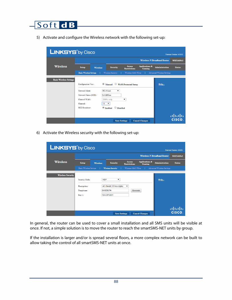
88
5) Activate and configure the Wireless network with the following set-up:
6) Activate the Wireless security with the following set-up:
In general, the router can be used to cover a small installation and all SMS units will be visible at once. If not, a simple solution is to move the router to reach the smartSMS-NET units by group.
If the installation is larger and/or is spread several floors, a more complex network can be built to allow taking the control of all smartSMS-NET units at once.

89
A-B.10 Configure an Access-Point
For a larger installation and if the pre-configured router is not enough to cover the entire building, alternative solutions can be developed. The solutions are based on the use of Ethernet access points (AP) and Ethernet switches connected with the pre-configured router or the main router of the building network. The next sections present these Ethernet devices.
The access points (AP) are wireless devices that can be placed in the building to reach SMS units by group in a way to cover the entire installation. We suggest using the WAP300N from Linksys:
The access point must be configured to allow an automatic connection with the SMS units. Follow these instructions:
1) If an access point is used, the main router must not have the same SSID (network name) or the Wireless of the router must be disabling to avoid conflicts (set the Network Mode at Disable in the Wireless tab during the configuration procedure of the router).
2) Then connect the access point to one of the four Ethernet ports of the router with an Ethernet cable and use an Internet browser to configure the AP. The IP address of the AP is determined by the main router (go to the configuration address of the router 192.168.1.1 first to know the IP address of the AP in the DHCP tab and the Status function). The user name of the AP is admin and the password is admin.
3) The Wireless network must be set with the following set-up:
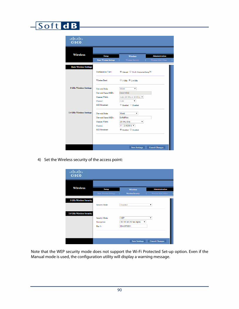
90
4) Set the Wireless security of the access point:
Note that the WEP security mode does not support the Wi-Fi Protected Set-up option. Even if the Manual mode is used, the configuration utility will display a warning message.

91
A-B.11 Use Ethernet Switches
The switches can be used when more Ethernet ports are required. The switches can be used as is without configuration. Simply connect the source Ethernet cable from the main router and the access point with the switch. We suggest using the SE1500 from Linksys.

92
Appendix C Perform Sound Level Measurements
A-C.1 Using the SLM Utility
The Project Manager Software includes a sound level meter (SLM) and spectrum analysis utility which is useful during smartSMS-NET system commissioning.
To open the SLM utility, click on the button from the “Tools” toolbar of the main interface or from the main setup interface in commissioning mode.
To use the SLM utility you need to have a compatible microphone. For more information on the microphone, refer to Appendix J, Set-Up the Calibration Microphone, p. 96 of this user guide.

93
Click on the button to start a measurement.
When performing a sound measurement, it is recommended to move slowly in the room in order to average the ambient sound of the room. Try to cover most of the room area the best you can while moving around the furniture.
A-C.2 Performing an Overall Measurement
An overall measurement is recommended at the end of the installation to measure the overall sound masking level and spectra in a zone.
1) Select the Target Curve against which you want to view the measurement results by clicking on the “Target Curve” field.
2) Select “Overall” from the “Measure” drop-down menu. This will perform an overall average during the measurement.
3) Start the measurement.

94
4) Walk quietly around the room while the measurement is running. 5) Stop the measurement. 6) Save the results by clicking on the “Save Data” button for documentation.
A-C.3 Performing a Live Measurement
A live measurement is recommended to see if the sound masking level and spectra is homogeneous (consistent) in a zone.
1) Select the Target Curve against which you want to view the measurement results by clicking on the “Target Curve” field.
2) Select “Live” from the “Measure” drop-down menu. This will show the live (current) sound level during the measurement.
3) Start the measurement. 4) Walk quietly around the room while the measurement is running and check if the sound
spectrum matches the target curve. Identify any location at which the sound spectrum is too high or too low compared to the target curve.
5) Stop the measurement.
This procedure may be needed in large open areas where the ambient sound environment can be heterogeneous.

95
A-C.4 Spectrum Types
Multiple sound spectrum types are available and can be selected from the drop-down menu.
A-C.5 Overall Measurement Data Types
Several data types are available for an overall measurement:
• Leq (Equivalent Sound Level): is the linear average of the sound level. This data type is the most common.
• LN% (Percentile Levels): is the statistical distribution of the sound level: • L5% is the sound level exceeded 5% of the time and represents the high sound levels. • L50% is the median sound level and is often used to calibrate the sound masking. • L95% is the sound level exceeded 95% of the time and represents the background
sound level.
Hint: The difference between L95% and L5% is an indicator of sound level variations during the measurement. If the L5% and L95% are close to each other it means the sound is very constant over the measurement duration. On the other hand, if the L5% and L95% are very far apart, it means that large variations in the sound are present.
• 1/3 Octave Bands:
• 1/24 Octave Bands:
• Narrow Bands:
• 1/1 Octave Bands:
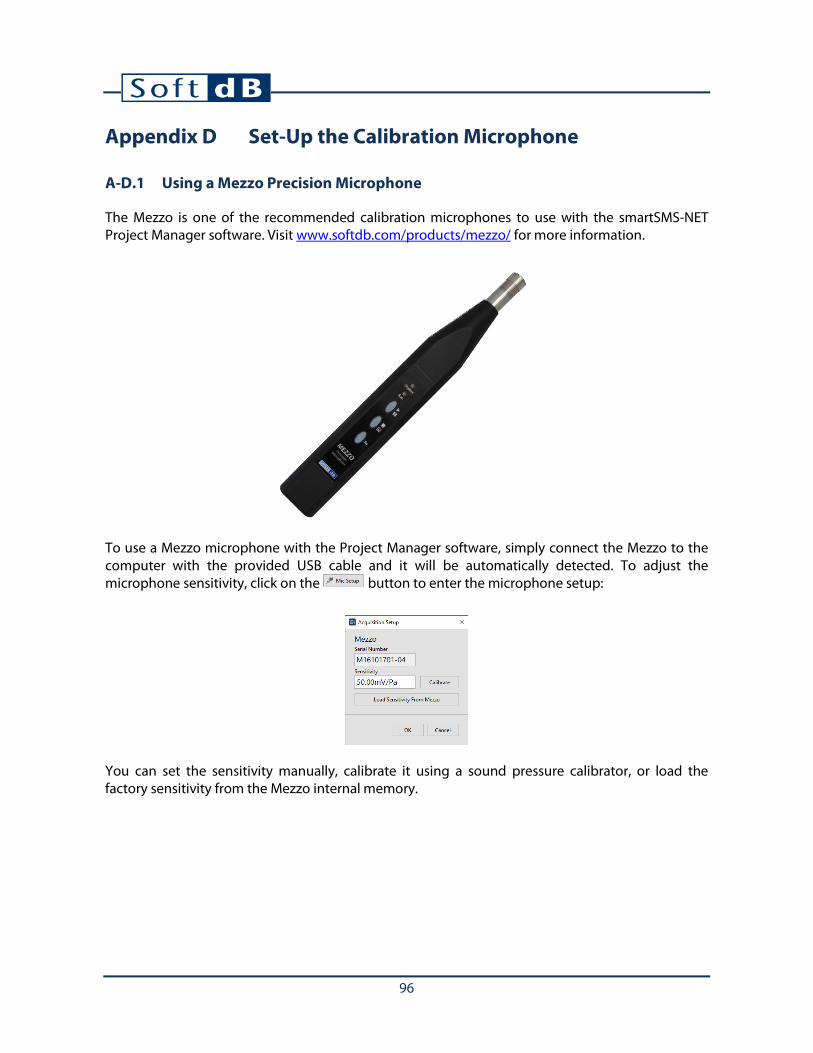
96
Appendix D Set-Up the Calibration Microphone
A-D.1 Using a Mezzo Precision Microphone
The Mezzo is one of the recommended calibration microphones to use with the smartSMS-NET Project Manager software. Visit www.softdb.com/products/mezzo/ for more information.
To use a Mezzo microphone with the Project Manager software, simply connect the Mezzo to the computer with the provided USB cable and it will be automatically detected. To adjust the microphone sensitivity, click on the button to enter the microphone setup:
You can set the sensitivity manually, calibrate it using a sound pressure calibrator, or load the factory sensitivity from the Mezzo internal memory.

97
A-D.2 Using a Piccolo-II Sound Level Meter
The Piccolo-II is one of the recommended calibration microphones to use with the smartSMS-NET Project Manager software. Visit www.softdb.com/products/piccolo2/ for more information.
To use a Piccolo-II sound level meter with the Project Manager software, simply connect the Piccolo-II to the computer with the provided USB cable and it will be automatically detected. To adjust the microphone sensitivity, click on the button to enter the microphone setup:
You can set the sensitivity manually, calibrate it using a sound pressure calibrator, or load the factory sensitivity from the Piccolo-II internal memory.
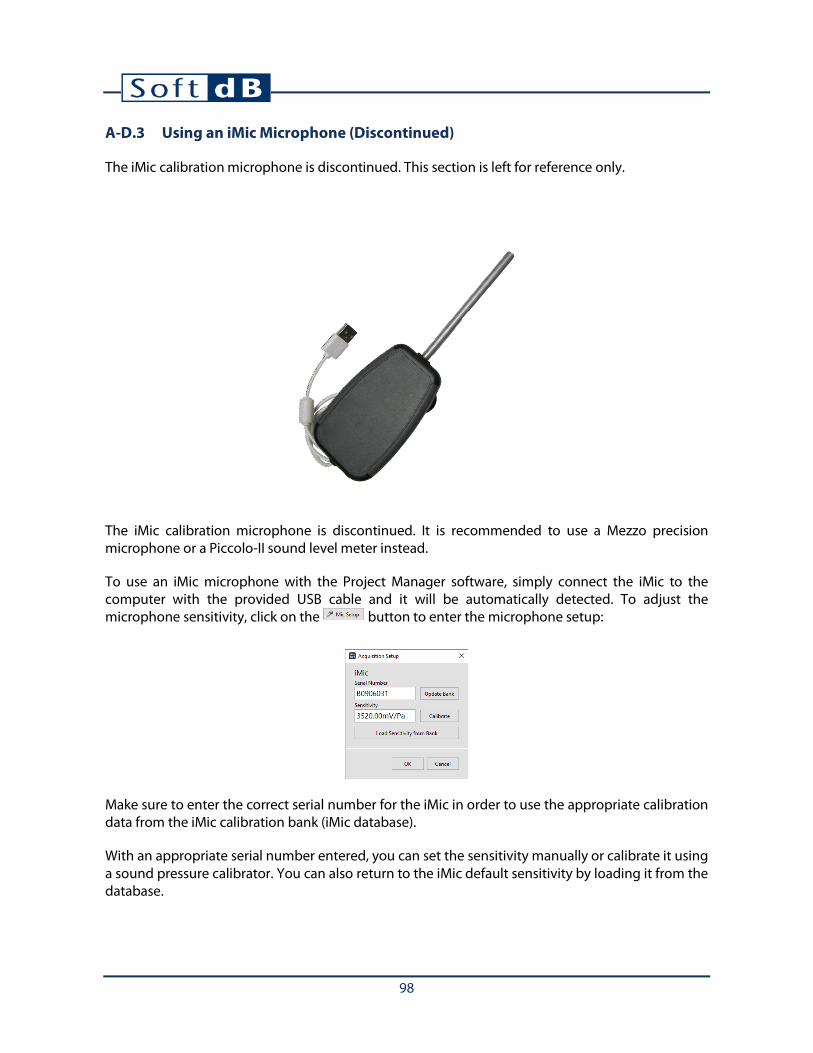
98
A-D.3 Using an iMic Microphone (Discontinued)
The iMic calibration microphone is discontinued. This section is left for reference only.
The iMic calibration microphone is discontinued. It is recommended to use a Mezzo precision microphone or a Piccolo-II sound level meter instead.
To use an iMic microphone with the Project Manager software, simply connect the iMic to the computer with the provided USB cable and it will be automatically detected. To adjust the microphone sensitivity, click on the button to enter the microphone setup:
Make sure to enter the correct serial number for the iMic in order to use the appropriate calibration data from the iMic calibration bank (iMic database).
With an appropriate serial number entered, you can set the sensitivity manually or calibrate it using a sound pressure calibrator. You can also return to the iMic default sensitivity by loading it from the database.

99
Appendix E Reset a smartSMS-NET Controller Unit to Factory Defaults
Follow these steps to reset a smartSMS-NET unit to the factory defaults:
1) Connect the smartSMS-NET units using a USB cable
2) Click on the button from the Tools toolbar in the Project Manager software.
3) Click “OK”.
WARNING: This utility will reset all the parameters to factory defaults!

100
Appendix F Change a smartSMS-NET Controller Network Setup
Follow these steps to change the network setup of a smartSMS-NET unit:
1) Connect the smartSMS-NET units using a USB cable
2) Click on the button from the Tools toolbar in the Project Manager software. 3) Enter the Network Name (SSID), Security and Password. 4) Click “OK”.
You can test the wireless communication of a unit by clicking on the button. The test will send data packets over WiFi and will evaluate the connection quality. The connection transfer speed should be over 200 kb/s (over 400kb/s is excellent).
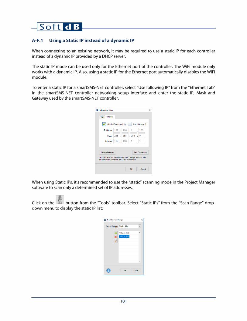
101
A-F.1 Using a Static IP instead of a dynamic IP
When connecting to an existing network, it may be required to use a static IP for each controller instead of a dynamic IP provided by a DHCP server.
The static IP mode can be used only for the Ethernet port of the controller. The WiFi module only works with a dynamic IP. Also, using a static IP for the Ethernet port automatically disables the WiFi module.
To enter a static IP for a smartSMS-NET controller, select “Use following IP” from the “Ethernet Tab” in the smartSMS-NET controller networking setup interface and enter the static IP, Mask and Gateway used by the smartSMS-NET controller.
When using Static IPs, it’s recommended to use the “static” scanning mode in the Project Manager software to scan only a determined set of IP addresses.
Click on the button from the “Tools” toolbar. Select “Static IPs” from the “Scan Range” drop-down menu to display the static IP list:

102
Appendix G Generating a Project Report for Crestron Integrator
The smartSMS-NET system is compatible with Crestron advanced control, automation, and unified communications systems 3. To integrate the smartSMS-NET system to a Crestron system, the smartSMS-NET project structure and layout must be forwarded to the Crestron Integrator.
This information is available as a document which can be created using the Project Manager Software. Use the “Generate Crestron Report” function in the “Project Info” interface to generate the report.
3 Crestron 3-SeriesProcessor only

103
Appendix H Post-Process Active Control History Files
The Project Manager Software includes a utility to post-process active-control history files.
The active control history files can be downloaded manually from the smartSMS-NET unit using the “Load Time History” button from the active control setup interface (see section View Active Control Time History, p. 43), or automatically through system monitoring (see section 9.2 Set-Up Automatic Active Control History, p. 65).
To access the active control time history post-processing utility, click on the button from the “Tools” toolbar and browse to the active control history file (*.oba) to load. Note that several files (of different weeks can be loaded at the same time):
The top graph shows the sound level recorded by the sensor: the red line shows the noise activity and the blue line shows the background noise.
The bottom graph shows the resulting active control gain from the processing of the sound levels using the active control parameters (Gain limits, Max step size, Sensitivity and Multiplier). For more information on the active control parameters refer to section 8.4 Set-Up the Sound Masking Active Volume Control, p. 38.
The above example shows 3 weeks of active control time history. Each day can be clearly identified by the noise activity period ranging from 8 AM to 6 PM.
Weeks and days can be superimposed to show trends:
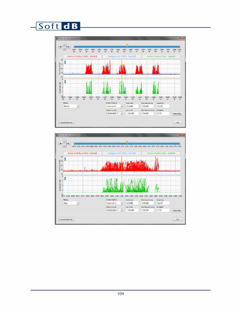
104

105
Appendix I Evaluating Speech Privacy
The Project Manager software includes a utility for evaluating Speech Privacy. Two methods are available for two common environments: Open Offices and Closed Offices. These two methods are based on the following standards:
• ASTM E 1130: Standard Test Method for Objective Measurement of Speech Privacy in Open Offices Using Articulation Index.
• ASTM E2638: Standard Test Method for Objective Measurement of the Speech Privacy Provided by a Closed Room.
To access the Speech Privacy Test utility, click on the button from the Tools toolbar.
Note: A measurement microphone such as the Mezzo Precision Microphone is required. For more information, refer to Appendix J, Set-Up the Calibration Microphone, p.96.
A-I.1 Configuring a Noise Source
A broadband noise source must be used to perform these tests. A smartSMS-NET controller along with a SMS-DIRECT loudspeaker can be used for this purpose.
To configure a controller with the appropriate parameters, connect a free controller (not associated
to a project) using the USB cable and click on the button from the Tools toolbar to access the Speech Privacy utility. The utility will detect the free controller and will ask to configure it.
When the configuration is done, the controller can be disconnected.
Note: The controller must be free to be configured. If the controller was previously associated with a project, you may have to reset it using the “Factory Reset”.

106
A-I.2 Performing a Speech Privacy Test for an Open Office
This test method describes a means of measuring speech privacy objectively between two locations in open offices. This test method relies upon the Articulation Index which predicts the intelligibility of speech for a pair of talker and listener in an open office.
Click on the button from the Tools toolbar to access the Speech Privacy Test utility. Click on the “New Test” button to create a new Privacy Test document:
On the Test Type prompt, select “Open Office”:

107
Note: Sound masking should be turned OFF during this test. A sound masking curve can be added after the test to see its effect on the Speech Privacy rating.
A-I.2.1 Measuring the Source Levels
Click on the “Add Measure” button to add a measurement to the test document.
On the new measurement prompt, select “Source” from the drop-down menu and click OK.
Position the noise source loudspeaker at the talker location with a tilt above horizontal and turn it ON. Measure the sound level at 0.9 m (3 ft.) from the loudspeaker. For better results, move the microphone slowly in an imaginary sphere of 0.3 m (1 ft.) diameter centered on this location.

108
When the measurement is done, click on “OK” to accept the measurement.

109
A-I.2.2 Measuring the Receiver Levels
Click on “Add Measure” and select “Receiver” from the drop-down menu on the measure type prompt.
With the noise powered ON, measure the sound level at the receiver location. For better results, move the microphone slowly in an imaginary sphere of 0.3 m (1 ft.) diameter centered on the listener location. When the measurement is done, click on “OK” to accept the measurement.

110
A-I.2.3 Measuring the Background Noise Levels
Click on “Add Measure” and select “Background” from the drop-down menu on the measure type prompt.
With the noise turned OFF, measure the sound level at the receiver location. For better results, move the microphone slowly in an imaginary sphere of 0.3 m (1 ft.) diameter centered on the listener location. When the measurement is done, click on “OK” to accept the measurement.
When the 3 main measurement types are performed, the Articulation Index and Privacy Index are calculated.

111
A-I.2.4 Adding Sound Masking
Click on the “Add Masking” button and select the sound masking curve from the library.
Upon adding a sound masking curve, the Articulation Index and Privacy Index are calculated.
A-I.2.5 Analyzing Results
The following table lists the relationship of Articulation Index and Privacy Index to subjective speech privacy ratings:
AI PI Subjective Rating
AI ≤ 0.05 PI ≥ 95 Confidential
0.05 < AI ≤ 0.2 95 > PI ≥ 80 Normal
0.2 < AI ≤ 0.3 80 > PI ≥ 70 Poor
0.3 < AI ≤ 0.4 70 > PI ≥ 60 Bad
0.4 < AI 60 > PI No Privacy
Note: For the current test, the speech privacy rating was PI 43% “No Privacy” without masking and increased to PI 85% “Normal” after adding sound Masking.

112
A-I.3 Performing a Speech Privacy Test for a Closed Office
This test method describes a test procedure for measuring the degree of speech privacy provided by a closed room. For conversations occurring within the room, and with a potential eavesdropper located outside the room.
Click on the button from the Tools toolbar to access the Speech Privacy Test utility. Click on the “New Test” button to create a new Privacy Test document:
On the Test Type prompt, select “Closed Office”:

113
Note: Sound masking should be turned OFF during this test. A sound masking curve can be added after the test to see its effect on the Speech Privacy rating.
A-I.3.1 Measuring the Source Levels
Click on the “Add Measure” button to add a measurement to the test document.
On the new measurement prompt, select “Source” from the drop-down menu and click OK.
Position the noise source loudspeaker at the talker location with a tilt above horizontal and turn it ON. Measure the sound level in the room. For better results, walk slowly in the room to evenly sample as much as practical of the measurement space.

114
When the measurement is done, click on “OK” to accept the measurement.

115
A-I.3.2 Measuring the Receiver Levels
Click on “Add Measure” and select “Receiver” from the drop-down menu on the measure type prompt.
With the noise powered ON, measure the sound level at the receiver location. For better results, move the microphone slowly in an imaginary sphere of 0.3 m (1 ft.) diameter centered on the listener location. When the measurement is done, click on “OK” to accept the measurement.

116
A-I.3.3 Measuring the Background Noise Levels
Click on “Add Measure” and select “Background” from the drop-down menu on the measure type prompt.
With the noise turned OFF, measure the sound level at the receiver location. For better results, move the microphone slowly in an imaginary sphere of 0.3 m (1 ft.) diameter centered on the listener location. When the measurement is done, click on “OK” to accept the measurement.
When the 3 main measurement types are performed, the Articulation Index and Privacy Index are calculated.

117
A-I.3.4 Adding Sound Masking
Click on the “Add Masking” button and select the sound masking curve from the library.
Upon adding a sound masking curve, the Articulation Index and Privacy Index are calculated.
A-I.3.5 Analyzing Results
The following table lists the relationship of Speech Privacy Class to subjective ratings of speech privacy:
SPC Subjective Rating
70 Minimal Privacy
75 Standard Privacy
80 Standard Security
85 High Security
90 Very High Security
Note: For the current test, the speech privacy rating was SPC 56.7 “No Privacy” without masking and increased to SPC 70.3 “Minimal Privacy” after adding sound Masking: an increase of 13.6.