project: ieee p802.15 working group for wireless personal area networks (wpans)
DESCRIPTION
Project: IEEE P802.15 Working Group for Wireless Personal Area Networks (WPANs) Submission Title: [Impulse Radio Signaling for Communication and Ranging] Date Submitted: [18 July 2005] Source: [Francois Chin, Yuen-Sam Kwok, Sai-Ho Wong, Zander Lei , Xiaoming Peng] - PowerPoint PPT PresentationTRANSCRIPT

July 2005
Francois Chin (I2R)Slide 1
doc.: IEEE 802.15-05-0231-07-004a
Submission
Project: IEEE P802.15 Working Group for Wireless Personal Area Networks Project: IEEE P802.15 Working Group for Wireless Personal Area Networks (WPANs)(WPANs)Submission Title: [Impulse Radio Signaling for Communication and Ranging]
Date Submitted: [18 July 2005]
Source: [Francois Chin, Yuen-Sam Kwok, Sai-Ho Wong, Zander Lei, Xiaoming Peng]
Company: [Institute for Infocomm Research, Singapore]
Address: [21 Heng Mui Keng Terrace, Singapore 119613]
Voice: [65-68745687] FAX: [65-67744990] E-Mail: [[email protected]]
Re: []
Abstract: [Presents signaling options to achieve precision ranging with both coherent and non-coherent receivers]Purpose: [To discuss which signal waveform would be the most feasible in terms of performance and implementation trade-offs]
Notice: This document has been prepared to assist the IEEE P802.15. It is offered as a basis for discussion and is not binding on the contributing individual(s) or organization(s). The material in this document is subject to change in form and content after further study. The contributor(s) reserve(s) the right to add, amend or withdraw material contained herein.
Release: The contributor acknowledges and accepts that this contribution becomes the property of IEEE and may be made publicly available by P802.15.

July 2005
Francois Chin (I2R)Slide 2
doc.: IEEE 802.15-05-0231-07-004a
Submission
Objectives
• PRF values for Mandatory and optional wider band systems
• Impulse Radio Signaling Proposal
• Common Signaling for different receivers, for Synchronisation, Ranging and Data Communications– Deterministic Pulse structures
– Optimal Receiver Code Sequences

July 2005
Francois Chin (I2R)Slide 3
doc.: IEEE 802.15-05-0231-07-004a
Submission
Minimum PRF Requirements (BW~500MHz)BW ~ 500 MHz
Technology CMOS 90nm 1.0 Vpp CMOS 90nm 1.0 Vpp
TChip (nsec) 2 2
Sequence Bipolar Ternary (equal ±1 & 0)
VPeak (v) 0.5 0.5
PAve (dBm) -14.3 -14.3
PPeak (dBm) 3.8 3.8
Chip Rate (MHz) @ VPeak ~7.75 ~15.5
PRF (MHz) @ VPeak ~7.75 ~7.75• Key Requirement is to meet CMOS Tx Vpp constraint
• For Ternary signaling– 1.0Vpp @ 15.5MHz CRF without backoff & perfect antenna – 1.2Vpp @ 15.5MHz CRF without backoff & 30% (or 1.5dB) feed loss– 1.0Vpp @ 15.5MHz CRF without 1.5dB backoff & 30% (or 1.5dB) feed loss

July 2005
Francois Chin (I2R)Slide 4
doc.: IEEE 802.15-05-0231-07-004a
Submission
Minimum PRF Requirements (BW~1.5GHz)BW ~ 1500 MHz
Technology CMOS 90nm 1.0 Vpp CMOS 90nm 1.0 Vpp
TChip (nsec) 0.66 0.66
BW (MHz) Bipolar Ternary (equal ±1 & 0)
VPeak (v) 0.5 0.5
PAve (dBm) -9.6 -9.6
PPeak (dBm) 4.4 4.4
Chip Rate (MHz) @ VPeak ~62 ~124
PRF (MHz) @ VPeak ~62 ~62• Key Requirement is to meet CMOS Tx Vpp constraint
• For Ternary signaling– 1.0Vpp @ 124MHz CRF without backoff & perfect antenna – 1.2Vpp @ 124MHz CRF without backoff & 30% (or 1.5dB) feed loss– 1.0Vpp @ 124MHz CRF without 1.5dB backoff & 30% (or 1.5dB) feed loss

July 2005
Francois Chin (I2R)Slide 5
doc.: IEEE 802.15-05-0231-07-004a
Submission
124 MHz CRF Mode is logical…• ~1.5GHz system, 3x larger bandwidth means
– 3x shorter pulse duration– 3x higher average transmit power
• The keep the same peak transmit power, ~1.5GHz system should have ~9x higher CRF (or PRF), compared to ~500MHz system• 124MHz CRF = 8 x 15.5 MHz CRF• Or in terms of PRF, 62 MHz = 8 x 7.75 MHz

July 2005
Francois Chin (I2R)Slide 6
doc.: IEEE 802.15-05-0231-07-004a
Submission
Minimum numbers of Chip Rates
• After considering antenna feed loss and PSD backoff, we have min 2 CRFs– ~15.5MHz for ~500MHz systems– ~124MHz for ~1500MHz systems

July 2005
Francois Chin (I2R)Slide 7
doc.: IEEE 802.15-05-0231-07-004a
Submission
Main Features of proposed Impulse Radio Signaling
Proposal main features:• Impulse-radio based (pulse-shape independent)
• Ternary Codes for Common Preamble & Data signaling for different classes of nodes / type of receivers (coherent / differential / noncoherent)
• Perfect balance ternary sequences for synchronisation & ranging preambles – Perfect Autocorrelation for coherent and energy detectors
• M-ary signaling for data transmission to achieve higher spreading gain - Robustness against SOP interference

July 2005
Francois Chin (I2R)Slide 8
doc.: IEEE 802.15-05-0231-07-004a
Submission
Key Features of proposed System• Impulse-radio based (pulse-shape independent)• Chip Repetition Frequency = ~15.5MHz (corresponding to
PRF of ~7.75MHz)• 1 Mbps mandatory and 10Mbps optional modes
• Ternary Codes for Common Preamble & Data signaling for different classes of nodes / type of receivers (coherent / differential / noncoherent)
• 31-Chip Perfect Balance Ternary Sequences (PBTS) for synchronisation & ranging preambles – Perfect Autocorrelation for coherent and energy detectors
• 16-ary Ternary Orthogonal Keying (derived from 31-chip sequence PBTS) for data transmission to achieve higher spreading gain - Robustness against SOP interference

July 2005
Francois Chin (I2R)Slide 9
doc.: IEEE 802.15-05-0231-07-004a
Submission
Criteria of Code Sequence Design
1. The code sequence should have perfect auto-correlation
properties for synchronisation and ranging (leading edge
detection) for all the below receivers
a. Coherent receiver
b. Energy detection receiver
c. Differential chip receiver
2. The sequence Set should have orthogonal (or near orthogonal)
cross correlation properties to minimise symbol decision error

July 2005
Francois Chin (I2R)Slide 10
doc.: IEEE 802.15-05-0231-07-004a
Submission
Base Sequence Set (31-chip Ternary)
These are Wideband Access-I2R proposed
Perfect Balance Ternary Sequences
for Preambles for Ranging
Seq 1 +0++000-+-++00++0+00-0000-0+0--
Seq 2 +-0+0+00+000+0++---0-+00-++0000
Seq 3 0+-+000+0-0++0-0000+-00-00-++++
Seq 4 0+0000-00-0+-00+++-+000-+0+++0-
Seq 5 -++0-+---00+00++0000+0+-0+0+000
Seq 6 0++-++0+000+00-0-0++0000--+00-+
• 31-chip Ternary Sequence Set• Only one base sequence and one fixed band (no hopping) will be
used by all devices in a piconet• Logical channels for support of multiple piconets
•6 sequences = 6 logical channels (e.g. overlapping piconets) for each FDM 500MHz Band
• The same base sequence will be used for •acquisition / ranging; and•Data transmission via symbol-to-chip mapping

July 2005
Francois Chin (I2R)Slide 11
doc.: IEEE 802.15-05-0231-07-004a
Submission
Base Sequence Properties (Auto-Corr.)
0 5 10 15 20 25 30 350
2
4
6
8
10
12
14
16Coherent Receiver: Periodic Autocorrelation Function
0 5 10 15 20 25 30 350
2
4
6
8
10
12
14
16Non-Coherent Receiver: Periodic Autocorrelation Function
•Perfect balance ternary sequences for synchronisation & ranging preambles – Perfect Autocorrelation for coherent and energy detectors

July 2005
Francois Chin (I2R)Slide 12
doc.: IEEE 802.15-05-0231-07-004a
Submission
Base Sequence Properties (Cross-Corr.)
0 5 10 15 20 25 30 35-4
-3
-2
-1
0
1
2
3
4Coherent Receiver: Periodic Cross-correlation Function
0 5 10 15 20 25 30 35-4
-3
-2
-1
0
1
2
3
4Non-Coherent Receiver: Periodic Cross-correlation Function
First 3 sequences have lowest possible cross-correlation values…

July 2005
Francois Chin (I2R)Slide 13
doc.: IEEE 802.15-05-0231-07-004a
Submission
Spectral PAR (PSD Backoff)PSD Backoff ~ 1.0dB @ 15.5 MHz

July 2005
Francois Chin (I2R)Slide 14
doc.: IEEE 802.15-05-0231-07-004a
Submission
Synchronisation Preamble
• The Ternary Base Sequence has excellent autocorrelation properties
• Synchronisation / Ranging Preamble is constructed by repeating the preamble
• Noted that with this new improved ternary sequences, there is no need for Receiver-specific signaling

July 2005
Francois Chin (I2R)Slide 15
doc.: IEEE 802.15-05-0231-07-004a
Submission
…………………………
1 2 3 314 5 6 7 8 30
Non-inverted pulses are blue,Inverted pulses are green.
CHIP Repetition Interval ~ 65ns
……………
Ternary Signaling for Preambles
Symbol Interval ~2us Symbol Interval ~2us
Synchronisation / Ranging preamble = Binary Base Sequence repeated For K times…
.................……………

July 2005
Francois Chin (I2R)Slide 16
doc.: IEEE 802.15-05-0231-07-004a
Submission
Modulation & Coding
Bit to symbol mapping: group every 4 bits into a symbol
Symbol-to-chip mapping:Each 2-bit symbol is mapped to one of 16 31-chip sequence, according to 16-ary Ternary Orthogonal Keying
Zero Padding:suggested 1 PRI for reducing inter-symbol interference
Symbol Repetition:for data rate and range scalability
Scrambling:with bipolar sequence @ 15.5MHz, to suppress cross correlation sidelobes due to excessive delay spread
Pulse Genarator: Transmit Ternary pulses @ 15.5MHz
Bit-to-Symbol
Symbol Repetition
CodedBits Scrambling
{0,1,-1} Ternary Sequence
Symbol-to-Chip
Pulse Generator
ZeroPadding

July 2005
Francois Chin (I2R)Slide 17
doc.: IEEE 802.15-05-0231-07-004a
Submission
Symbol Cyclic shift to right by n chips, n=
32-Chip value
0000 0 + 0 + + 0 0 0 - + - + + 0 0 + + 0 + 0 0 - 0 0 0 0 - 0 + 0 - - 0
0001 2 - - + 0 + + 0 0 0 - + - + + 0 0 + + 0 + 0 0 - 0 0 0 0 - 0 + 0 0
0011 4 + 0 - - + 0 + + 0 0 0 - + - + + 0 0 + + 0 + 0 0 - 0 0 0 0 – 0 0
0010 6 – 0 + 0 - - + 0 + + 0 0 0 - + - + + 0 0 + + 0 + 0 0 - 0 0 0 0 0
0110 8 0 0 - 0 + 0 - - + 0 + + 0 0 0 - + - + + 0 0 + + 0 + 0 0 - 0 0 0
0111 10 0 0 0 0 - 0 + 0 - - + 0 + + 0 0 0 - + - + + 0 0 + + 0 + 0 0 – 0
0101 12 0 - 0 0 0 0 - 0 + 0 - - + 0 + + 0 0 0 - + - + + 0 0 + + 0 + 0 0
0100 14 + 0 0 - 0 0 0 0 - 0 + 0 - - + 0 + + 0 0 0 - + - + + 0 0 + + 0 0
1100 16 + 0 + 0 0 - 0 0 0 0 - 0 + 0 - - + 0 + + 0 0 0 - + - + + 0 0 + 0
1101 18 0 + + 0 + 0 0 - 0 0 0 0 - 0 + 0 - - + 0 + + 0 0 0 - + - + + 0 0
1111 20 + 0 0 + + 0 + 0 0 - 0 0 0 0 - 0 + 0 - - + 0 + + 0 0 0 - + - + 0
1110 22 - + + 0 0 + + 0 + 0 0 - 0 0 0 0 - 0 + 0 - - + 0 + + 0 0 0 - + 0
1010 24 - + - + + 0 0 + + 0 + 0 0 - 0 0 0 0 - 0 + 0 - - + 0 + + 0 0 0 0
1011 26 0 0 - + - + + 0 0 + + 0 + 0 0 - 0 0 0 0 - 0 + 0 - - + 0 + + 0 0
1001 28 + 0 0 0 - + - + + 0 0 + + 0 + 0 0 - 0 0 0 0 - 0 + 0 - - + 0 + 0
1000 30 0 + + 0 0 0 - + - + + 0 0 + + 0 + 0 0 - 0 0 0 0 - 0 + 0 - - + 0
Symbol-to-Chip Mapping:Gray coded 16-ary Ternary Orthogonal Keying

July 2005
Francois Chin (I2R)Slide 18
doc.: IEEE 802.15-05-0231-07-004a
Submission
Code Sequences for different Receivers
Receiver Type
Preamble / Data Sequence
Receive Sequence
Coherent Ternary Ternary
Differential Chip
Ternary Differential(Ternary)
Energy Detector
Ternary Bipolar
•For both Preamble and Data•Ternary to Bipolar conversion ± → +
0 → -

July 2005
Francois Chin (I2R)Slide 19
doc.: IEEE 802.15-05-0231-07-004a
Submission
Cross Sequence Correlation Properties for Coherent Receiver
RX Mapping Matrix * TX Mapping Matrix' =
For Coherent Detector, RX Mapping Matrix = TX Mapping Matrix

July 2005
Francois Chin (I2R)Slide 20
doc.: IEEE 802.15-05-0231-07-004a
Submission
Symbol Cyclic shift to right by n chips, n=
32-Chip value
0000 0 + - + + - - - + + + + + - - + + - + - - + - - - - + - + - + + -
0001 2 + + + - + + - - - + + + + + - - + + - + - - + - - - - + - + - -
0011 4 + - + + + - + + - - - + + + + + - - + + - + - - + - - - - – - -
0010 6 – - + - + + + - + + - - - + + + + + - - + + - + - - + - - - - -
0110 8 - - + - + - + + + - + + - - - + + + + + - - + + - + - - + - - -
0111 10 - - - - + - + - + + + - + + - - - + + + + + - - + + - + - - + -
0101 12 - + - - - - + - + - + + + - + + - - - + + + + + - - + + - + - -
0100 14 + - - + - - - - + - + - + + + - + + - - - + + + + + - - + + - -
1100 16 + - + - - + - - - - + - + - + + + - + + - - - + + + + + - - + -
1101 18 - + + - + - - + - - - - + - + - + + + - + + - - - + + + + + - -
1111 20 + - - + + - + - - + - - - - + - + - + + + - + + - - - + + + + -
1110 22 + + + - - + + - + - - + - - - - + - + - + + + - + + - - - + + -
1010 24 + + + + + - - + + - + - - + - - - - + - + - + + + - + + - - - -
1011 26 - - + + + + + - - + + - + - - + - - - - + - + - + + + - + + - -
1001 28 + - - - + + + + + - - + + - + - - + - - - - + - + - + + + - + -
1000 30 - + + - - - + + + + + - - + + - + - - + - - - - + - + - + + + -
Rx Sequence for Energy Detector
Ternary to Bipolar conversion of Base Sequence #1

July 2005
Francois Chin (I2R)Slide 21
doc.: IEEE 802.15-05-0231-07-004a
Submission
Sync & Ranging - Energy Detector operation (example)
BPF ( )2 LPF / integrator
ADC
Sample Rate 1/Tc
SlidingCorrelator
Noncoherent detection of OOK
{1,-1} Binary Sequence
Soft output
Unipolar M-Seq [+ + + 0 0 0 + + 0 + + + 0 + 0 + 0 0 0 0 + 0 0 + 0 + + 0 0 + + ]
Bipolar M-Seq [+ + + - - - + + - + + + - + - + - - - - + - - + - + + - - + + ]
Ternary Seq [+ - - 0 0 0 + - 0 + + + 0 + 0 - 0 0 0 0 + 0 0 - 0 - + 0 0 - - ]
After Square Law & Integration in PRI
0 20 40 60 80 100 120 140 160-4
-2
0
2
4
6
8
10
12
14
16Energy Detector Correlator output (Ternary signaling, Bipolar Despreading Seq)
In AWGN

July 2005
Francois Chin (I2R)Slide 22
doc.: IEEE 802.15-05-0231-07-004a
Submission
Cross Sequence Correlation Properties for Energy Detector
RX Mapping Matrix * abs(TX Mapping Matrix)' =
For Energy Detector, RX Mapping Matrix = Ternary2Bipolar(TX Mapping Matrix)

July 2005
Francois Chin (I2R)Slide 23
doc.: IEEE 802.15-05-0231-07-004a
Submission
Why M-ary Orthogonal Keying ?
• Good coding gain as M-ary Orthogonal Keying is power-limited coding
•More coding gain is achieved with higher M values•Marginal gain for M > 16
• Robust against SOP interference & inter-pulse interference due to high despreading gain per M-ary symbol

July 2005
Francois Chin (I2R)Slide 24
doc.: IEEE 802.15-05-0231-07-004a
Submission
Simulation Results
AWGN Performance & Multipath Performance
I. For Coherent Symbol Detector
II. For Energy Detector
III. For differential Chip Detector (to be provided later)
July 2005
Francois Chin (I2R)Slide 25
doc.: IEEE 802.15-05-0231-07-004a
Submission
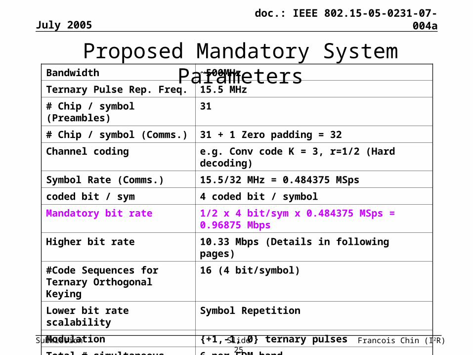
Bandwidth ~500MHz
Ternary Pulse Rep. Freq. 15.5 MHz
# Chip / symbol (Preambles) 31
# Chip / symbol (Comms.) 31 + 1 Zero padding = 32
Channel coding e.g. Conv code K = 3, r=1/2 (Hard decoding)
Symbol Rate (Comms.) 15.5/32 MHz = 0.484375 MSps
coded bit / sym 4 coded bit / symbol
Mandatory bit rate 1/2 x 4 bit/sym x 0.484375 MSps = 0.96875 Mbps
Higher bit rate 10.33 Mbps (Details in following pages)
#Code Sequences for Ternary Orthogonal Keying
16 (4 bit/symbol)
Lower bit rate scalability Symbol Repetition
Modulation {+1,-1, 0} ternary pulses
Total # simultaneous piconets supported
6 per FDM band
Multple access for piconets CDM (fixed code) + FDM (fixed band)
Proposed Mandatory System Parameters

July 2005
Francois Chin (I2R)Slide 26
doc.: IEEE 802.15-05-0231-07-004a
Submission
Multipath Performance (1 Mbps, 500MHz BW)
0 5 10 15 20 25 3010
-4
10-3
10-2
10-1
100
Eb/N0
PE
R
32-Chip , 1/2 rate CC (K=5)
AWGN CohAWGN EDCM1 Coh 1-RAKECM1 ED 1-RAKECM1 Coh 4-RAKECM1 ED 4-RAKECM8 Coh 1-RAKECM8 ED 1-RAKECM8 Coh 4-RAKECM8 ED 4-RAKE
• Random transmit scrambling seq.
• Coherent and energy detectors
• AWGN, CM1 & CM8• 1-Rake & 4-Rake • Ideal Channel
acquisition + timing estimation
• Benefit of ½ rate CC not obvious in isolated piconet operation; advantage may be in SOP operation

July 2005
Francois Chin (I2R)Slide 27
doc.: IEEE 802.15-05-0231-07-004a
Submission
SOP + Multipath (1 Mbps, 500MHz BW)
To be provided later

July 2005
Francois Chin (I2R)Slide 28
doc.: IEEE 802.15-05-0231-07-004a
Submission
Bandwidth ~500MHz
Pulse Rep. Freq. 15.5 MHz
# Chip / symbol (Preamble) 31
# Chip / symbol (Comms.) 1
Channel coding e.g. Conv code K = 3, r=2/3
Symbol Rate 15.5 MSps
coded bit / sym 1 coded bit / symbol
Max bit rate 2/3 x 1 bit/sym x 15.5 MSps = 10.33 Mbps
#Code Sequences for Orthogonal Keying
Nil
Modulation {+1,-1} bipolar pulses
Total # simultaneous piconets supported
-
Multple access for piconets CDM (fixed code per piconet)
Proposed Mandatory System Parameters (Max Bit Rate Mode)

July 2005
Francois Chin (I2R)Slide 29
doc.: IEEE 802.15-05-0231-07-004a
Submission
Multipath Performance (10 Mbps, 500MHz BW)
0 2 4 6 8 10 12 14 16 18 2010
-4
10-3
10-2
10-1
100
PE
R
Eb/N
0
Coherent Detector performance, Ternary Signaling @ 15.5MHz with BW = 496MHz
AWGN CC onlyCM1 CC only 1-RAKECM1 CC only 4-RAKE
• No Ternary Ortho.Keying
• Coherent detector only• AWGN, CM1• 1-Rake & 4-Rake • Ideal Channel
acquisition + timing estimation

July 2005
Francois Chin (I2R)Slide 30
doc.: IEEE 802.15-05-0231-07-004a
Submission
Proposed Optional Wider Band ~ 1.5GHz systems

July 2005
Francois Chin (I2R)Slide 31
doc.: IEEE 802.15-05-0231-07-004a
Submission
Key Features of proposed wider band system• Impulse-radio based (pulse-shape independent)• Chip Repetition Frequency = ~124MHz (corresponding to PRF of
~62MHz)• 1 Mbps mandatory and 10Mbps optional modes
• Ternary Codes for Common Preamble & Data signaling for different classes of nodes / type of receivers (coherent / differential / noncoherent)
• 127-Chip Perfect balance ternary sequences for synchronisation & ranging preambles – Perfect Autocorrelation for coherent and energy detectors
• 16-ary Ternary Orthogonal Keying (with 256-chip sequence) for data transmission to achieve higher spreading gain - Robustness against SOP interference, especially in 1.5GHz system (without FDMA for SOP)

July 2005
Francois Chin (I2R)Slide 32
doc.: IEEE 802.15-05-0231-07-004a
Submission
Base Sequence Set (127-chip Ternary)
These are Wideband Access-I2R proposed
Perfect Balance Ternary Sequences
for Preambles for Ranging
Seq 1 0000+++-++-0+0+0-00++00-++0+--0-00+0++000+-0+++-0-+0-0--0--00+00
+000+-+0000+0-++--00+0+0+--00--0+000-00+-+-000-0-0000++00000+00
Seq 2 -00+++0+-0+++0+00+00+0-+000--+00+0000-0-++00000++0-000000-00---+
++-000-0-0+0-+++00+-00-0+000+000+-0000--+-0--+-+0+0-+0+0+00-+0-
Seq 3 +-00-000+-000-0--+0000+0000+-0+00000+++--0++000000+0+0++0+++----00-+0+-0+0-0+000-00+00-+00++-+000+++0+--0-0-+-+0-00-0+-00+0-00+
Seq 4 000-0-0-0-++-+0+00+0+000-+0+++000----+++0000+++0--++00+0-+00+00+
000000-000-00--000-0+-+0-0+-0-+00000+-00++0-0+00--+00++-+0+-0+0
Seq 5 0+-0++0+000+--+-0000++-000+0+00++000000++0-0--+0-00+0-0+0++0+--0
0+0000+000+00-00+-++0-0+00000-0-+-+00---0----+++0+-00+0-+000-+0
• 127-chip Ternary Sequence Set• Only one base sequence and one fixed band (no hopping) will be
used by all devices in a piconet• Logical channels for support of multiple piconets
•5 sequences = 5 logical channels (e.g. overlapping piconets) for 1500MHz Band
• The same base sequence will be used for •acquisition / ranging; and•Data transmission via symbol-to-chip mapping

July 2005
Francois Chin (I2R)Slide 33
doc.: IEEE 802.15-05-0231-07-004a
Submission
…………………………
1 2 3 1274 5 6 7 8 126
Non-inverted pulses are blue,Inverted pulses are green.
CHIP Repetition Interval ~ 8.1ns
……………
Ternary Signaling for Preambles
Symbol Interval ~1.03us Symbol Interval ~1.03us
Synchronisation / Ranging preamble = Binary Base Sequence repeated For K times…
.................……………

July 2005
Francois Chin (I2R)Slide 34
doc.: IEEE 802.15-05-0231-07-004a
Submission
Bandwidth 1488MHz
Ternary Pulse Rep. Freq. 124 MHz
# Chip / symbol (Preamble) 127
# Chip / symbol (Comms.) 256 (Details later)
Channel coding e.g. Conv code K = 3, r=1/2
Symbol Rate 124/256 MHz = 0.484375 MSps
coded bit / sym 4 coded bit / symbol
Mandatory bit rate 1/2 x 4 bit/sym x 0.484375 MSps = 0.96875 Mbps
Max bit rate 10.33 Mbps (see next page)
#Code Sequences for Ternary Orthogonal Keying
16 (4 bit/symbol)
(16*k-chip cyclic right shift, across the 16 sequences)
Lower bit rate scalability Symbol Repetition
Modulation {+1,-1, 0} ternary pulses
Total # simultaneous piconets supported
>6
Multple access for piconets CDM (fixed code per piconet)
Proposed Optional Wider Band System

July 2005
Francois Chin (I2R)Slide 35
doc.: IEEE 802.15-05-0231-07-004a
Submission
Multipath Performance (1 Mbps, 1500MHz BW)
• Random Transmit scrambling seq.
• Coherent and energy detectors
• AWGN, CM1 & CM8• 1-Rake & 4-Rake • Ideal Channel
acquisition + timing estimation
• Benefit of ½ rate CC not obvious in isolated piconet operation; advantage may be in SOP operation

July 2005
Francois Chin (I2R)Slide 36
doc.: IEEE 802.15-05-0231-07-004a
Submission
SOP + Multipath (1 Mbps, 1500MHz BW)
To be provided later

July 2005
Francois Chin (I2R)Slide 37
doc.: IEEE 802.15-05-0231-07-004a
Submission
Bandwidth 1488 MHz
Pulse Rep. Freq. 124 MHz
# Chip / symbol (Preamble) 127
# Chip / symbol (Comms.) 32 (identical to that for ~500MHz system)
Channel coding e.g. Conv code K = 3, r=2/3
Symbol Rate 124/32 MHz = 3.875 MSps
coded bit / sym 4 coded bit / symbol
Max bit rate 2/3 x 4 bit/sym x 3.875 MSps = 10.33 Mbps
#Code Sequences for Ternary Orthogonal Keying
16 (4 bit/symbol)
(identical to that for ~500MHz system)
Modulation {+1,-1, 0} ternary pulses
Total # simultaneous piconets supported
>6
Multple access for piconets CDM (fixed code per piconet)
Proposed Optional Wider Band System (Max Bit Rate)

July 2005
Francois Chin (I2R)Slide 38
doc.: IEEE 802.15-05-0231-07-004a
Submission
0 2 4 6 8 10 12 14 16 18 2010
-4
10-3
10-2
10-1
100
Coherent Detector performance,Ternary Signaling @ 124MHz with BW = 1488MHz
PE
R
Eb/N
0
AWGN BOK onlyCM1 BOK only 1-RAKE
CM1 BOK only 4-RAKE
AWGN CC+BOK
CM1 CC+BOK 1-RAKECM1 CC+BOK 4-RAKE
Multipath Performance (10 Mbps, 1500MHz BW)
• Random Transmit scrambling seq.
• Coherent and energy detectors
• AWGN, CM1 & CM8• 1-Rake & 4-Rake • Ideal Channel
acquisition + timing estimation
• Benefit of ½ rate CC not obvious in isolated piconet operation; advantage may be in SOP operation

July 2005
Francois Chin (I2R)Slide 39
doc.: IEEE 802.15-05-0231-07-004a
Submission
SummaryThe proposed Impulse-radio based system:• has ternary signaling only that
– Can be received simultaneously by different types of receivers, namely coherent, differential, and energy detectors
– Can be used for both Preamble and Comm. simultaneously• Synchronisation & Ranging – Repeated Ternary Base Sequence for
preambles– Simple sliding correlator can be used for Ranging & Sync
• Data Communications – 4bit/symbol Ternary Orthogonal Keying Symbol (with cyclic shift version of base sequence + zero padding)– Good coding gain due to M-ary orthogonal keying– Is robust against SOP interference due to high spreading gain per
symbol