project gemini familiarization manual vol1 sec2
DESCRIPTION
How the Gemini Spacecraft worked.TRANSCRIPT

MAC
CONFIDENTIAL CONTROL NO. C- 119162
PROJECT GEMINISUPPLEMENT
familiarizationJnanual
SEDR300 COPYNO.
LONG RANGE and MODIFIEDCONFIGURA TIONS
1"HIS PUBLICATION SUPPLEMENTSS,EDR300 VOLUME 1
IMFCDONNELL
THIS DOCUMENT SUPER- /SEDESDOCUMENT DATED
!15 MARCH 1964AND IN-CLUDES CHANGE DATED31 DECEMBER1964
NOTICE: This material contains information affecting the nationaldefense of the United States within the meaning of the Espionage laws,Title 18, U.S.C., Sections 793 and 794, the transmission or revelation
._ of which in any manner to an unauthorized person is prohibited by law.
GROUP-4
DOWNGRADED AT 3-YEAR INTERVALS;DECLASSIFIEDAFTER 12 YEARS
30 SEPTEMBER1965CONFIDENTIAL
CONFIDENTIAL
GUIDANCE andCONTROL SYSTEM
SectionVIII
TABLE OF CONTENTS
TITLE PAGE
GENERAL ....................................................... 8-3ATTITUDE CONTROL AND
MANEUVER ELECTRONICS ......................... 8-13 .....................,o_ooo.o_::::: :°°°or,
INERTIAL GUIDANCE SYSTEM ...................... 8-41 :_L.:i:_ii-._".-E_.--._._._•°°°o.°°.°o. *°,°o°4 °_
. oRIzoNSENSOeSYSTEM........................._-,_o iiiiiiiiiii!ii!HiiiiiiHiiTIME REFERENCE SYSTEM ............................. 8-210 _'.::'"_.:'_:-":'-:":':-.::'_
:::::::::::::::::::::::::::
PRO PULSIO N SYSTEM .................................. 8- 253 iiiiiiiiiiiiHiiiiHiiiii!iiii!!iii!iiiiiiiiiiiiiiiiiliiiiiiiiiiii!ii!iHiiiiiiii:::::::::::::::::::::::::::
iiiiiiiiiiiiiiiiiiiiiiilHii• .......... ......o.o.oo....
iiiiiiiiiiiiiiiiiiiiiiiiiii,...°..o.....,.....,.°°°,.,
i_iii_!Hiiiiiiiiiiiiiiiii!ii!i!iiiiiiiiiiiiiiiiiiiiii:::::::::::::::::::::::::::
.... iiiiiiiiiiiiii!Hiiiii!!iiiliiiiiii_!i!ii_iiiiiiiiii_iliiiiiiiiiii_i!_i_!i!_iiii.. .........................
8-z/-2 iiiiiiiiiiii!!i!!!!!i!!iii!CONFIDENTIAL
GONFIDENTIAL
s=o=300PROJECT GEMINI
GUIDanCE AND CONTROL - GENERAL
GENERAL
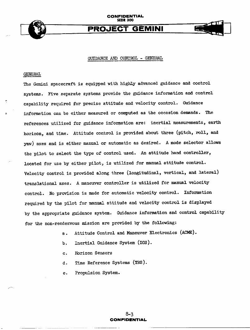
The Gemini spacecraft is equipped with highly advanced guidance and control
systems. Five separate systems provide the guidance information and control
capability required for precise attitude and velocity control. Guidance
information can be either measured or com_uted as the occasion demands. The
references utilized for guidance information are: inertial measurements, earth
horizon, and time. Attitude control is provided about three (pitch, roll, and
yaw) axes and is either manual or automatic as desired. A mode selector allows
the pilot to select the type of control used. An attitude hand controller,
located for use by either pilot, is utilized for manual attitude control.
Velocity control is provided a_ng three (longitudinal, vertical, and lateral)
translational axes. A maneuver controller is utilized for manual velocity
control. No provision is made for automatic velocity control. Information
required by the pilot for man_gL attitude and velocity control is displayed
by the appropriate guidance system. Guidance information and control capability
for the non-rendezvous mission are provided by the following:
a. Attitude Control and Maneuver Electronics (ACME).
b. Inertial Guidance System (IGS).
c. Horizon Sensors
d. Time Reference Systems (TRS).
e. Propulsion System.
8-3
(;ON ISlDIENTIA L

CONFIDENTIALSEDR300
I
SYST_4 FUNCTIONS
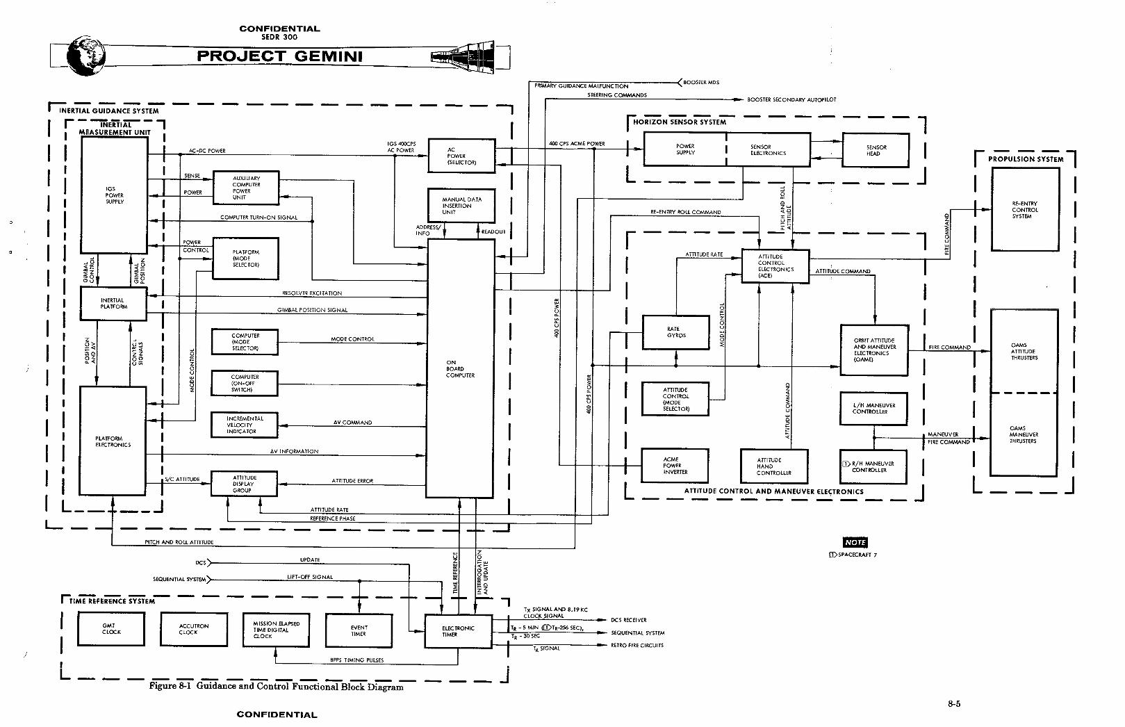
The various guidance and control systems are all functionally related. The
functional relationship between each of the systems is illustrated in Figure 8-1.
Attitude Control and Maneuver Electronics
The Attitude Control and Maneuver Electronics System converts input signals to
thruster firing co--has for the propulsion system. Input signals to ACME are
provided by the attitude hand controller, the IGS, or the Horizon Sensors
depending on the mode of operation.
Inertial Guidance System
The Inertial Guidance System provides inertial attitude and acceleration infor-
mation, guidance computations, and displays. The inertial attitude and acceler-
ation information is used for computations and display purposes. Computations
are used for back-up ascent guidance, orbit correction and re-entry guidance.
IKsplays are utilized by the crew for reference information and as a basis for
manual control.
Hor,izon Sensors
Horizon Sensors provide a reference to the earth local vertical during orbit.
Pitch and roll error signals are sulyplledto ACME for automatic attitude control
and to the IGS for platform allgnment.
Time Reference S_rstem
The Time Reference System provides a time base for all guidance and control
functions. Time is displayed for pilot reference in both clock and digital
form. The TRS also provides timing signals to the computer and the Sequential
System.
CONFIDENTIAL

J

(;ONFIOIrNTIAL
SEDR300
PRMINI
Propul _ion S_stem
The Propulsion System provides the thrust required for spacecraft maneuvers.
Thrusters are provided for both translational and attitude control. Firing
coum_uds for the Prop_1 rion System are provided by ACME.
GUIDANCE AND CONTROL MISSION
The functions of the guidance and control system are dependent on mission phase.
The mission is divided into five phases for explanation purposes. The phases
are: pre-launch, launch, orbit, retrograde, and re-entry.
Pre-Launch Phase
Pre-launch phase is utilized for check-out and progrs_m_ug of guidance and
control syst_ma. Parameters requi:redfor inserti,_nin the desired orbit are
inserted in the computer. The IMU is aligned to the local vertical and the
desired launch azimuth. Power is turned on to the various systems and mode
selectors are placed in their launch position. Check-out and parameter insertion
are performed in the last 150 minutes prior to launch.
Launch Phase
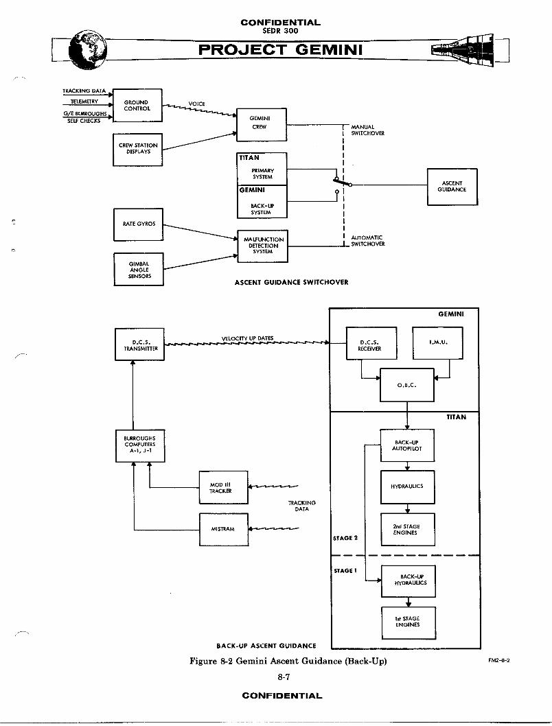
Guidance and control from lift-off through SSECO is provided by the booster
guidance system. However, in case of booster guidance malfunction the IGS can
assume control. Provision is made for either automatic or manual switchover
to back-up (Gemini) guidance. Fis.ure8-2 indicates both methods of switchover
and the back-up method of controlling the booster during ascent. The IGS
monitors attitude and acceleratiozLparameters throughout the launch phase.
Ground tracking information is used to continuously update computer parameters.
8-6CONP'IDIENTIAL
CONFIDENTIAL
s o.ooPROJECT GEMINI
TRACK,NGDATAj _._TE_M_RY;I G_OONOCONTROL
G,_ Et_ROUGH$ _JSELF CHECKS Vl GEMINI
CREW I MANUAL
_f "1 I SW_TCHOVER
CREW STATION JDISPLAYS J
ITAN II .
- [ [SYSTEMASCENT
;EMINI 9 J GUIDANCEI
RACK-_ I
RATE GYROSI
MALFUNCTION J AUTOMATICDETECTION J SWITCHOVER
_- SYSTEM
I GIMBAL
ANGLESENSORS
ASCENT GUIDANCE SWITCHOVER
GEMINI
D.C.S. L.___ D.C.S. ,.M.U.
TRANSMITTER _ RECEIVER
JO.B,C.
TITAN
I BURROUGHS J
COMPUTERS BACK-UPA-I, J-1 AUTOP] LOT
MOD III HYDRAULICSTRACKER
TRACKING
DATA
t MIS1T_AM _-w 2nd STAGE
ENGINESSTAGE 2
/
STAGE1 J BACK-UPHYDRAULICS
1st STAGEENGINES
BACK-UP ASCENT GUIDANCE
Figure 13-2 Gemini Ascent Guidance (Back-Up) FM2-8-2
8-7
CONFIDENTIAL

CONFIDENTIAL
SEDR300
PROJECT GEMINI
At SSECO, the remaining velocity required for insertion is displayed. The c_--*_nd
pilot will, after separation, we the prop,,l__ion system to increase spacecraft
velocity as required for insertion in the desired orbit. Insertion will t_e
place approx_tel_ 580 miles down rathe at an inertial velocity of approxi-
mately 25,770 feet per second.
Orbit Phase
Orbit phase is utilized for checkout and align,_.nt of systems, orbital maneu-
vers, experiments and preparation for retrograde and re-entry. Tm,_diately
after insertion a series of system checks will he performed to assure the
capability of guidance and control systems. Guidance computations and measure-
ments are checked for accuracy a_ainst ground tracking informqtion. Systems
are updated and aligned by ground command (DCS) or by the pilot. After com-
pletion of system checks, the orbital maneuvers and experiments can be performed.
During the final orbit, guidance and control systems are re-aligned in prepara-
tion for retrograde and re-entry.
Retrograde Phase
Retrograde phase begins approx_,_te_y five mlnutes before retrofire. The com-
puter is placed in re-entry mode and begins collecting data for re-entry com-
putations. The Time Reference System provides indications at TR- 5 minutes
(TR-276 seconds on spacecraft 7), TR-30 seconds, and TR. At TR-? minutes or
TR-256 seconds (depending on spacecraft number) a minus 16 degree bias is placed
on the pitch attitude needle. The Propulsion System is switched from orbit
attitude and maneuver to re-entry control. Spacecraft attitude is controlled
manually during retrograde. Retrograde acceleration and attitude are monitored
8-8CONFIDENTIAL

CONFIDENTIAL._ SEDR 300
i- PROJECT GEMINI
by the IGS and velocity cha-ges are displayed for reference.
Re-Entr_ Phase
Re-entry phase begins _mmediately after retrofire. The event timer counts
through zero at retrograde and will be counting down from one hundred mlnutes
(60 minutes on spacecraft 7) dlzringre-entry phase. After retrofire the retro-
grade adapter and horizon scan]_r heads are Jettisoned. Shortly after retro-
grade, the pilot orients the s_acecraft to re-entry attitude (0° pitch, 180°
roll, 0° yaw). Re-entry attitude is held until the computer re-entry program
starts. At approximately 400,000 feet altitude, the computer re-entry program
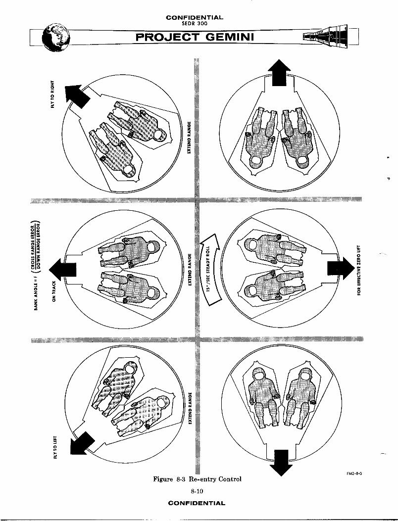
starts and the pilot has a choice of ,_nual or automatic control. For mauual
_ control, the pilot selects 1_-]_'_ 1_'i_ _ or for automatic control, the 1_-_'#
mode is utilized. In the automatic mode, the computer controls spacecraft roll
attitude. For either mode of control, the flight director is referenced to the
computer and indicates computed attitude corn=ands. The purpose of the computer
re-entry program is to control the point of touchdown and control re-entry
heating. By controlling the spacecraft roll attitude and rate, it is possible to
change the down range touchdown point by approx1,--telyB00 miles and the cross
range touchdown by 25 miles left or right. The relationship between roll atti-
tude or rate and direction of ll_t is illustrated in Figure 8-B. The roll control
starts at approximately 400,000 feet and ends at 90,000 feet. Re-entry phase
ends at 80,000 feet when the computer co-,a_ds an attitude suitable for drogue
chute deployment.
S"
8-9CONFIDENTIAL
CONFIDENTIALSEDR 300
*ili0 :8_:::N
00
Oo _ Nu a a¢
z _
Z
..{_®
FM2-8-3
Figure 8-3 Re-entry Cont:_ol
8-10
CONFIDENTIAL
CONFIDENTIAL
ATTITUDE CONTROL AND
MANEUVERING ELECTRONICS
TABLE OF CONTENTS
TITLE PAGE
SYSTEM DESCRIPTION .......... 8-13SYSTEM OPERATION ........... 8-13
GENERAL 813FUN CTIONA L ()P_.t_ATI()N (ACI_E)" [ [ . 8-14
_ MODE OPF RATION ........ 8-18
SYSTEM UNrl_ ___. . ._ __ ___ . . 8.9.6ATTITUDE CONTROL'ELR CTRONICS . 8-26ORBIT ATTITUDE AND MANEUVER
ELECTRONICS .......... 8-34
RATE GYRO PACKAGE______ ...... 8-36POWER I_FVERTER PACKAGE .... 8-36
p-.
8-11
CONFIDENTIAL
CONFIDENTIALSEDR300
MANEUVER
CONTROLLER
_sCAcECRAFT 7 ONLY)
RATE GYRO
_ _ _ CONTROL
_ , SWITCHES
_" ATTITUDE HAND
_ OILER
/" _"_ MODE SELECTOR
I / /
ATTITUDE CONTROL
ELECTRONICS PACKAGE _. _i
RATE GYR(
MANEUVER ELECTRONICSPACKAGE
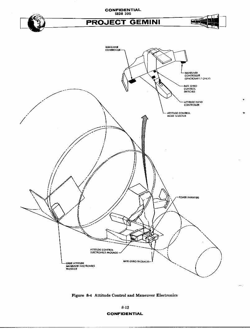
Figure 8-4 Attitude Control and Maneuver Electronics
8-12
CONFIDENTIAL

OONFIDI[NTIAL
PROJECT GEMINI
ACME SYSTEM
SYST_ DESCRIPTION
The Attitude Control and Maneuver Electronics (ACME) System (Figure 8-4)
provides the control circuitry to attain and/or maintain a desired spacecraft
attitude or velocity. The ACME accepts signal inputs from the attitude hand
controller, maneuver hand controller, horizon sensors, platform or the computer;
processes the signal, and applies a firing command to the appropriate Prop-lRion
System solenoid valves. ACME is composed of four separate sub-systems : Attitude
Control Electronics (ACE), Orbit Attitude and Maneuver Electronics (OAME),
a Power Inverter and two identical Rate Gyro Packages. The ACE, power inverter
_ and rate _-ro packages are inst_lled in the center bay of the re-entry module.
The OAME package is located in the equipment section of the adapter. Total
weight of the ACME System is approximately 40 pounds.
The ACME provides the capability of automatic or m_nual attitude control, with
seven separate, selectable modes of operation. The horizon sensor, the inertial
platform or the computer provide the reference for automatic modes of operation.
The attitude hand controller provides the input signals for manual modes of
attitude control, and the maneuver hand controller provides input signals for
translational maneuvers.
SYST_4 OPERATION
G_VERAL
F_ The ACME provides attitude control, automatic or manual, during all flight phases
of the spacecraft mission. Rate gyro inputs to ACE are used to damp spacecraft
8-13
CONFIDENTIAL
CONFIDENTIAL
.EO..ooPROJECT GEMINI
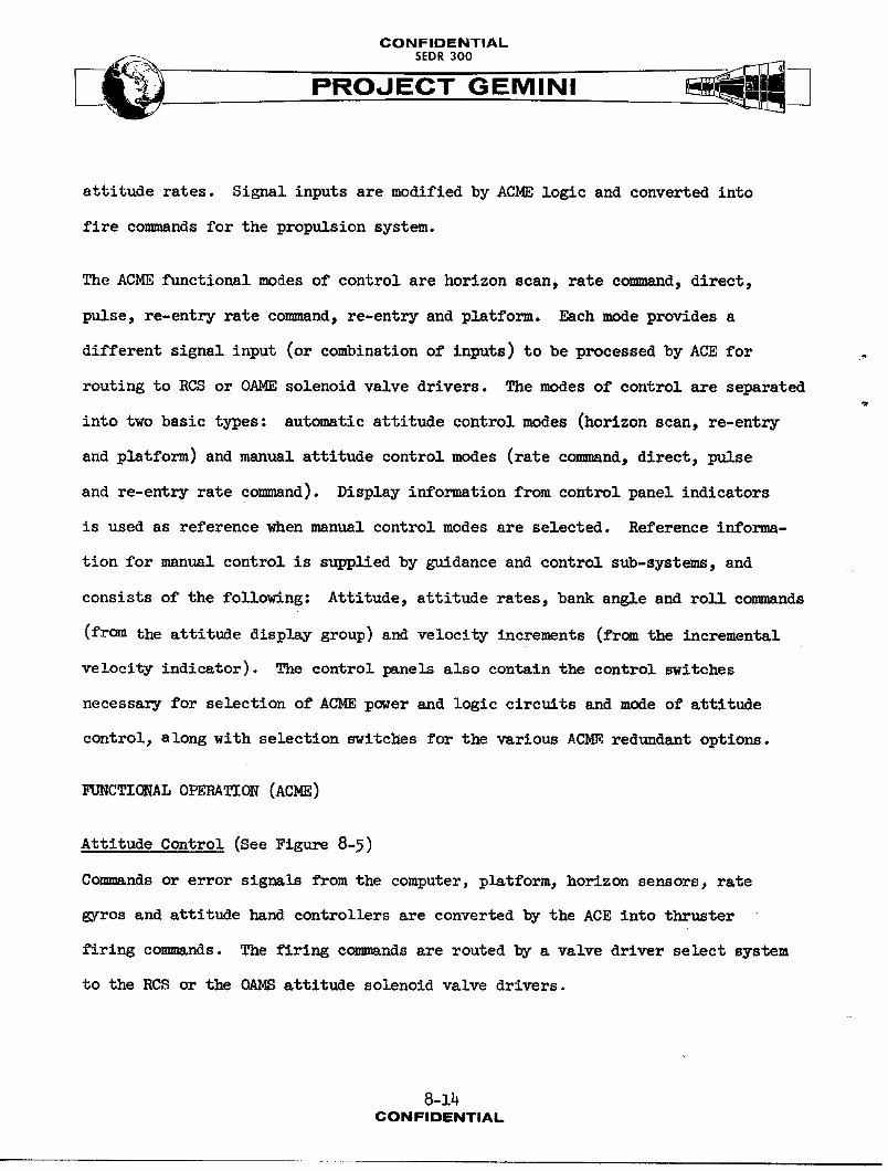
attitude rates. Signal inputs are modified by ACHE logic and converted into
fire COmmRnds for the propulsion system.
The ACME functional modes of control are horizon scan, rate commnd, direct,
pulse, re-entry rate co,_and, re-entry and platform. Each mode provides a
different signal input (or combination of inputs) to be processed by ACE for
routing to RCS or OAME solenoid valve drivers. The modes of control are separated
into two basic types: automatic attitude control modes (horizon scan, re-entry
and platform) and manual attitude control modes (rate command, direct, pulse
and re-entry rate command). Display information from control panel indicators
is used as reference when manual control modes are selected. Reference informa-
tion for manual control is supplied by guidance and control sub-systems, and
consists of the following: Attitude, attitude rates, bank angle and roll corn,ends
(from the attitude display group) and velocity increments (from the incremental
velocity indicator). The control panels also contain the control switches
necessary for selection of ACHE power and logic circuits and mode of attitude
control, along with selection switches for the various ACHE redundant options.
Zd_CTIC_ALOPERATION(ACHE)
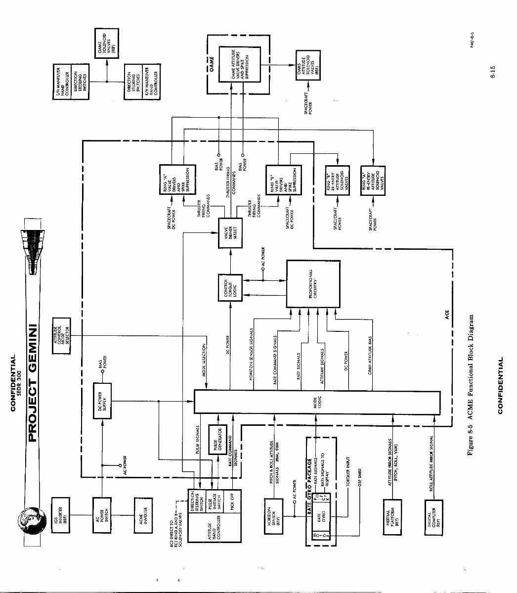
Attitude Control (See Figure 8-5)
Commands or error signals from the computer, platform, horizon sensors, rate
gyros and attitude hand controllers are converted by the ACE into thruster
firing corn.ends. The firing c_nds are routed by a valve driver select system
to the RCS or the (kaJ¢8attitude solenoid valve drivers.
8-14CONFIDENTIAL

CONFIDENTIAL
PROJECT GEMINIk
Signal inputs to the ACE are of three types: AC attitude signals, DC attitude
signals and AC attitude rate signals. These signals are selected and distributed
by ACE mode logic switching circuits. Selected signals are channeled through
the proportional circuitry which amplifies, sums and demodulates the signal
inputs into a DC analog output. Horizon Sensor (DC attitude) signals are con-
verted to AC prior to entering the proportional circuitry. The analog signals
are then converted by control torque logic switch circuitry to a positive or
negative discrete, the output consisting of either positive or negative thruster
firing eomm_nds. These CO,hands are routed by the valve driver select circuit
to the RCS, (ring A and/or ring B) valve drivers, or to the OAMS attitude valve
drivers for a fire command to the appropriate thruster valves. Zener diode
spike suppression circuits, limit the voltages generated across the solenoid
valves during current interruptions.
Attitude Hand Controller
Spacecraft attitude may be manually controlled by use of the attitude hand
controller and a visual reference. Controller outputs are rate, pulse or
direct comm_nd signals, (plus a hand controller position output to telemetry)
depending on the control mode selection. Output signals are produced by handle
movements_ about each respective axis, from the centered position. Rate signals
produced are proportional to the amount of control displacement from a center
deadband. Direct and/or pulse signals are produced when the hand controller is
displaced past a preset threshold or deadband. Pulse signals trigger a cali-
brated on time of a pulse generator in ACE. The control handle must be returned
to a neutral position before another single pulse can be commsuded. Details
8-16
CONFIDENTIAL
CONFIDENTIALSEDR 300
of each mode of control may be found in the mode operation paragraph.
RCS Direct
The RCS direct mode is selectable as an alternate means of manually firing the
RCS thrusters, and by-passes the ACE. The DIRECT position of each of the RCS
RING A and/or RING B switches provides a circuit ground to 12 attitude hand
controller RCS direct switches. The ground is then applied directly to the
required thruster solenoid valves through appropriate hand contro!ler displace-
ments. This RCS mode of operation is intended for standby or emergency control
only.
Maneuver Hand Controller
Translational maneuvers of the spacecraft, in the horizontal, longitudinal
and vertical planes, are comm_nded by themaneuver hand controller. Displace-
ment of the controller from the centered or neutral position to any of the six
translational directions produces a direct on command to the respective solenoid
valve drivers.
Rate G_ros
The function of the rate gyro package is to sense angular rate about the pitch,
yaw and roll axes of the spacecraft and provide an output slgnalprsportio_eS
to that sensed rate. Selection of certain control modes provides gyro inputs
to ACE for angular rate damping. Additional information concerning the rate
gyros may be found in the paragraph on system units.
8-17CONFIDENTIAL
CONFIDENTIAL
_. SEDR300
PROJECT GEMINI
Power Inverter
The power inverter provides the ACHE and horizon sensors with AC power. Space-
craft DC power is converted to 26V, 400 cps. (The IGS inverter provides the
primary source of AC excitation. ) The ACME inverter is utilized when the
inertial measuring unit is not operating. Additional information on the
power inverter may be found in the paragraph on system unlts.
MODE OPERATION
Control of spacecraft attitude is accomplished through the selection of seven
functional modes of control. Each mode of control is utilized for a specific
purpose or type of ACME operation in conjunction with various mission phases.
Each mode of operation provides either automatic or manual spacecraft control
through the switching of input signals to ACE. In addition, the mode logic
circuits de-energize all unused circuits within the ACE during use of the
horizon scan mode to conserve power. Switching is performed by transistors
at the signal level and by relays at the power level. The operation of each
mode of control is explained in the following paragraphs.
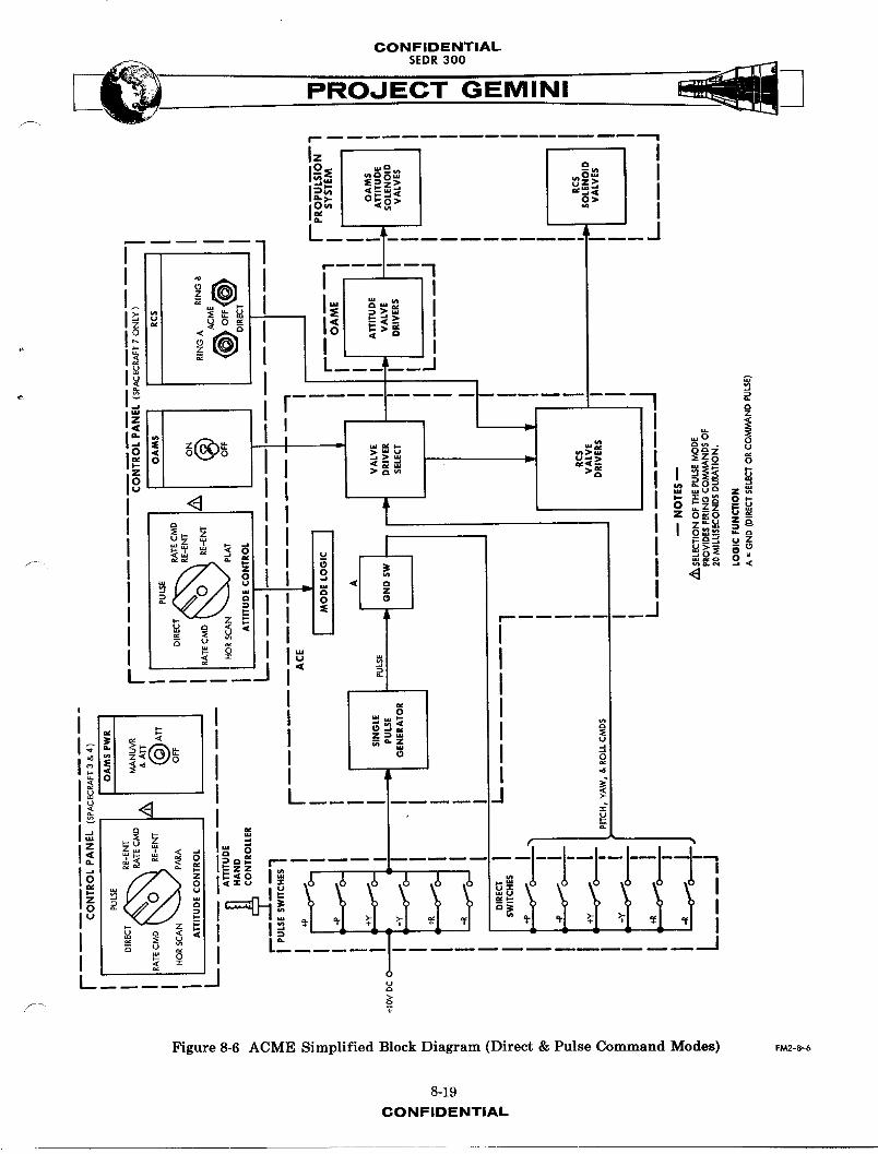
Direct Mode (M_)
In this mode, thruster firing co_nds are applied directly to the RCS or OAME
attitude solenoid valve drivers, by actuation of the attitude hand controller
direct switches (Figure 8-6). Selection of the DIRECT mode applies an ON
bias voltage to a transistor designated ground switch A. Conduction of the
transistor completes a circuit to ground which is common to one side of the
hand controller direct switches. The transistor remains on as long as the direct
8-18
CONFIDENTIAL
CONFIDENTIALSEDR 300
r
I- I_ _c3Nw Ow I
':_ =E_2> _z> ;cn _ ..j <C _<[
I0-._)- 0 b- t._> O> !
, I [: T ........ -::--J
. _o + I_1 _;i II
o , L__;!11 , :i_ _0 0
> '_" _o__u Z_
_ _o_o0__0 -
_,-z I z 'v' z_
_- 2: !
__ I
I1_ _ I
iil+l++o' 1I I -
_] t J !.
I:_ _ _
'++_'<i+_ ..... -"......... "--"!i - +++ +1+ tt f tt !I_,
I _| x
Figure 8-6 ACME Simplified Block Diagram (Direct & Pulse Command Modes) F_-_-_
8-19
CONFIDENTIAL

CONFIDENTIAL
PROJECT GEMINI
mode is selected.
Three sets of six norm-11y open switch contacts provide the co_m_nd signals in
the pitch, yaw and roll axis and will close when the hand controller is moved
beyond a preset threshold (2.5 degrees) of handle travel. Movement in the
desired direction applies a ground from switch A directly to the valve driver
relative to that direction and in turn fires the proper thruster(s). Thrusters
continue firing as long as the hand controller is displaced beyond the 2.5
degree threshold. This mode of operation is optional at all times.
Pulse (Y_)
In this mode, the attitude commands initiated by hand controller displacement
fire a single p,_laegenerator in the ACE (Figure 8-6). The pulse mode energizes
the generator, _11owing it to fire for a fixed duration when a pulse command is
received. COmmnuds originate every time one of _he six normally open pulse
switch contacts of the hand controller is closed. This triggers the generator
and applies a bias voltage pulse for a 20 m_11_second ON duration to ground
switch A. This ground is then applied to the RCS or OAME attitude valve drivers,
through the actuated hand controller direct switches as a comm_nd for thruster
firing. Co,v_nds may be initiated in the pitch, yaw or roll axis by moving the
control handle in the desired direction beyond a preset threshold (3.5 degrees).
Thrusters fire for 20 mi11_seconds each time the handle is displaced beyond 3.5
degrees. This mode is optional at _11 times and will normally be used during
platform alignment.
8-20CONP'IOENTIAL

CONFIDENTIAL
PROJECT GEMINI
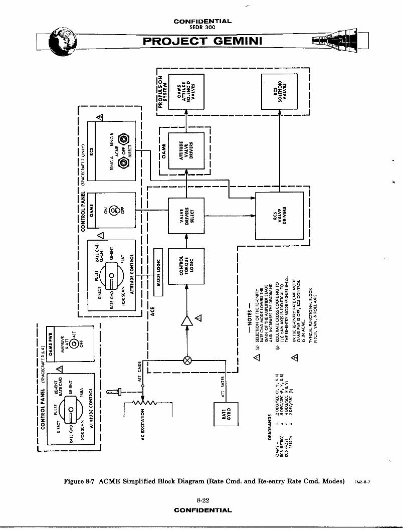
Rate Co_nd Mode (M_)
In this mode, spacecraft attitude rate about each axis is proportional to the
attitude hand controller displacement from the neutral deadband (Figure 8-7).
(Pickoff excitation is zero for displacements less thRn i degree of handle travel,
providing a non-operational area or deadband.) C_m,_nd signals, generated by
handle displacements, are compared to rate gyro outputs and when the difference
exceeds the damping deadband, thruster firing occurs. Signals originate from
potentiometers in the hand controller and outputs are directly proportional to
handle displacement. A maximum co,_nd signal to ACE produces an Rn_,I_ rate of
I0 degree/second about the pitch and yaw axis and 15 degrees/second about the
rol 1 axis.
Automatic, closed loop stabilization of spacecraft rates is provided from the
sensing of an_11_r rates by the rate gyro package. With the absence of hand
controller co,_nd sign_, spacecraft rates about each axis are damped to within
+0.2 degrees/second with OAME attitude control _-d to _rithin_+0.5degree/second
with RCS attitude control. Output sign_1_ from the rate gyros are used to
produce fire co-_-ds until the rate sig-A1 is within the damping deadband.
This mode is optional at _11 times and will normS1y be used during transla-
tional thrusting or attitude changes.
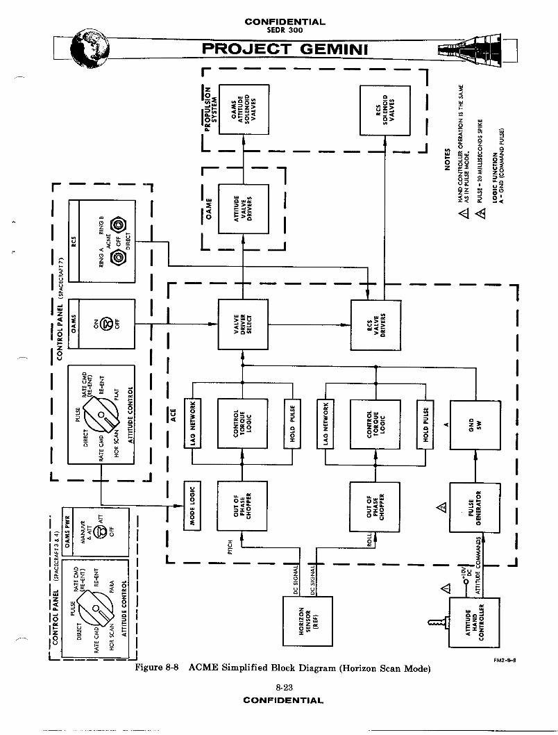
Horizon Scan Mode (_fl
In this automatic co--rid mode, horizon sensor out!_uts (pitch and roll) are
processed by the ACE to orient and hold the spacecraft within a desired attitude
deadband during orbit (Figure 8-8). Pitch attitude is maintained automatic-liy
to within +_5degrees of the -5 degree reference and roll attitude is m_ntained
8-2lCONFIDENTIAL
CONFIDENTIALSEDR 300
I_ a -- im,m_l "°"_=o> _ I
io_.l_oo_ > o> iI"I I
[ < ..... mI •
s: _N I.o o __r i
li "" II
I < I m' L_ I fI -_ _ I
m _'A-_-KLI_L)- II o _ oo. I) i ° _
I _ _ : I I _° "__oL ! _ I = _-_-o o__o_ o_> . .
' I / I o_o_ __ _I o_a__ =_
'I_I_ 'I I _ I _ '_I__ I -"I_ "_ _ _
I "°" I
' I ,I 0 _ _'_
i_ _ _ _-_I _ ,_"
I J _'_
Figure 8-7 ACME Simplified Block Diagram (Rate Cmd. and Re-entry Rate Cmd. Modes) _-8-_
8-22
CONFIDENTIAL

CONFIDENTIAL
PROJECT GEMINI
automAticAlly to within +5 degrees of the zero degree n_11. Control about the
yaw axis is acco_lished by command from the attitude hand controller, in the
same manner as in the pulse mode. i_11_e control about the pitch and roll axes
is _Iso available to supplement automatic control. A bias voltage is summed
with the horizon sensor pitch output to maintain the 5 degree pitch down orien-
tation. When the attitude error (pitch or roll) exceeds the 5 degree control
deadband, the output of the ACE on-off logic is a pulse firing co,m_nd. The
pulse on time is for 18 m_11_seconds and the pulse repetition frequency is
dependent upon how much the attitude error exceeds the 5 degree deadband. A
lag network in this mode provides a pseudo rate feedback for rate damping, without
having to use the power cons_-,_ng rate gyros.
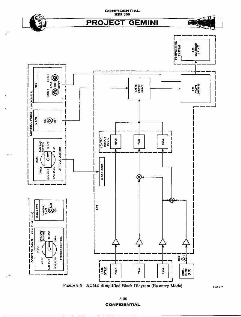
Re-entry Mode (MS)
In this automatic comm_nd mode, spacecraft angular rates about the pitch and
yaw axes are damped to within +5 degrees/second and to within +2 degrees/second
about the roll axis (Figure 8-9). Roll attitude is controlled to within +2
degrees of the attitude commanded by the digital computer input to ACE. Com-
puter roll input to ACE consists of either a bank angle attitude co,and or a
fixed roll rate comm_nd, depending on the relationship between the predicted
touchdown point and the desired touchdown point. When a roll rate is commanded,
roll to yaw crosscoupling is provided to minimize the spacecraft lift vector.
Re-entr_/Rate Co,m_nd Mode (M_D)
In this manual comm_ud mode, spacecraft rates are controlled by rate commands
from the attitude hand control_er. The method is identical to the rate comm_nd
8-24CONFIDENTIAL
CONFIDENTIAL
PROJECT GEMINI
I"
ii l- o>- ,,", 1' II I r 1
i@_ I ' I I ,
I I :I _' _ =., I= uo I_ I I
I ,,, o _ _..u ">= I@_I i °" =I = Ii I II ]
igll" 'I I
,' ,'! 0EJ__1 I __._-. I /FIFE_ I I
I _(,,_ _ I ooI =__=_ I:_oi _ U _ =u
I _ I I _ _,=I .J I
;
II
Z< (3
_(_ I II II I
_ _ I I_"" I I /\ / /\ z_
,Figure 8-9 ACME Simplified Block Diagram (Re-entry Node) F_a-8-_
8-25
CONFIDENTIAL
CONFIDENTIAL
___ SEDR 300 __
PROJECT GEMINI
mode with the addition of roll-yaw rate crosscoupling. Angular rate damping
about the three axes is identical to the re-entry mode. The computer bank angle
and roll rate commnds do not automatically control the spacecraft but are
provided on the control panel displays where they can be used as a reference
for initiating ._nual re-entry roll comrm,_,',rl_.
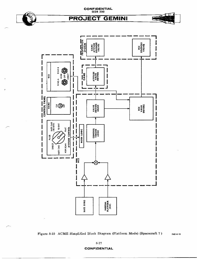
Platform (M6)
This attitude control mode is used on spacecraft 7 to maintain a fixed attitude
in all three axes, with respect to the inertial platform. Spacecraft attitude is
held automatically to within 1.1 degrees of the platform attitude. A horizontal
attitude, with respect to the earth, can be held if the inertial platform is in the
orbit rate or alignment modes of operation. Spacecraft attitude rates are _mp.ed
to within 0.5 degrees/second. The primary purpose of this mode is to automati-
cally hold an inertial spacecraft attitude. PLAT mode is also useful for
maintaining spacecraft attitude during fine alignment of the platform. (See
Figure 8-10. )
Aborts - ACME/RCS
Rate command mode of ACME will be utilized for attitude control during All
abort modes. Control over the RCS Ring A and Ring B switches, for a mode 2
abort, is automatically switched to ACME by the abort sequential relays.
SYST_ UNITS
ATTITUDE CONTROL ELECTRONICS (ACE)
The ACE package (Figure 8-4) weighs approximately 17 pounds, has a removable
cover and contains ten removable module boards. These boards make up the ACE
8-26CON FIDENTIAL
CONFIDENTIALSEDR 300
__ io_._._o> o> I
r----I- --:- _--7
"-I I '_ Io_ t I°_ II- I
_.1, _ _ I
I I
"!i 'Figure 8-10 ACME Simplified Block Diagram (Platform Mode) (Spacecraft 7 ) F_-8-io
8-27
CONFIDENTIAL
CONFIDENTIAL
__ SEDR 300 __
PROJECT GEMINI
logic circuitry and consist of the following: a mode logic board, an AC signal
processing board, three axis logic boards, three relay boards, a power supply
board (+20, +i0, -i0 VDC) and a lag network board. These replaceable module
boards perform the signal processing for the three axis control and convert
signal inputs into an appropriate thruster firing co--rid.
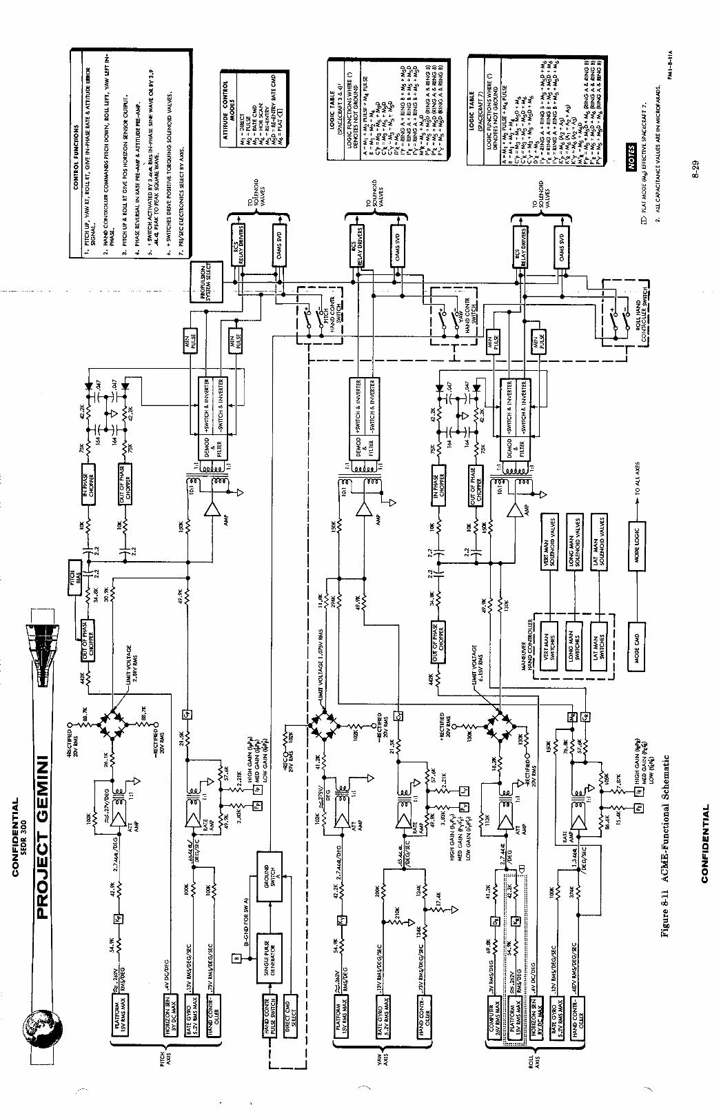
FunctionA_!C_eration
Input signals to ACE are dependent on attitude requirements of the spacecraft
and are used to obtain an attitude or attitude rate correction. A functional
schematic of the ACE is shown in Figure 8-11 and is sectioned to show signal
processing in each of the three axis channels. ACE mode logic circuits are
represented by the legend blocks at the left of Figure 8-11. The selection
of a mode of attitude control, initiates transistor switching in the logic
circuits pertaining to that mode. The required input signal is then switched
into the proper ACE channel for processing. Additional information on mode
logic switching n_y be found in the mode selection paragraph. Proportional
circuitry consists of the signal amplifier stages (attitude and rate), switch
amplifiers and the demodulator/filter stages. Attitude and rate sig_n1_ to
each of the pitch, yaw and roll channels are AC and are amplified to opera-
tion_! levels by the attitude and rate amplifiers. The outputs are s_maed and
fed to the switch nmplifiers. The output of the switch amplifier is coupled
to the demodulator stage where it is converted to a DC, positive or negative,
analog signal. The DC sign,S then energizes either the positive or negative,
low-hysteresis transistor switches in the control torque logic section.
An 18 millisecond switch on time control is provided by the minimum pulse
8-28CONFIDENTIAL

CONFIDENTIAL
L__V - PROJECT GEMINI
generators. Horizon sensor DC signals are chopped and amplified by the s_itch
amplifiers, then demodulated in the same manner as AC signals. The valve
driver select circuits control power and signal distribution to OA_ and RCS
attitude valve drivers. To turn off the 0AME control system, power is applied
to de-energlzed relays, the normally closed contacts of which complete the power
and signal inputs to the OA_. Power may then be applied to the RCS ring A
and/or ring B valve drivers for RCS attitude control. The ring A and ring B
RCS valve drivers consists of relays, energized by transistor relay drivers.
_de Lo6ic Switchin 6
Transistor switching provides the control for attitude mode signal selections,
along with ACE power distribution in the horizon scan mode. These switches
are represented by blocks in Figure 8-i1. The logic function for each block
is explained in the truth table at the right of Figure 8-11 as being ground or
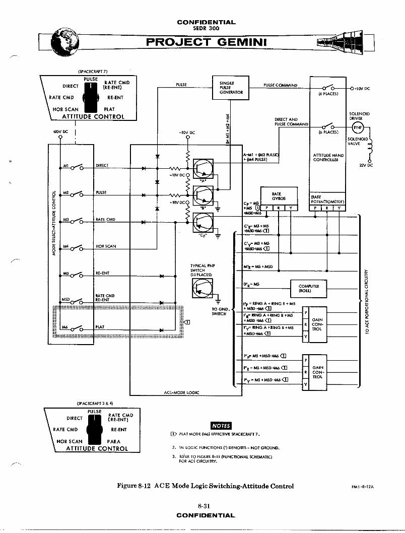
not ground. Figure 8-12 shows how mode control of signal selections is accom-
plashed. The transistor switches provide a grounded or not grounded condition
to attitude signals, by being in a conducting or not conducting state. Attitude
reference and comm_ud signals are obtained by selecting the appropriate mode
of control switch position. This applies a +20 VDC bias voltage to the base
of a PNP transistor, biasing it to cut off. This ungrounded state _11ows the
desired signal to be applied to the ACE amplifiers. The mode 1 (direct), and
mode 2 (pulse), and one of the M4 (hot scan) logic switches are NPN transistors,
and conduct with the application of +20 VDC. This provides a ground circuit
for hand controller comm_nds. The pulse generator signal provides the bias
voltage to turn on switch A when in the pulse or orbit modes.
8-30CONFIDENTIAL
CONFIDENTIAL
PROJECT GEMINI/
DIR T P_uLSmE RATE CMD SINGLE J PULSE COMMANDEC (RE_ENT)\ PULSE PULSE _ - O*;OvOC
m
\ il OENEPA,ORI (,PLACES,V ATmC'°I! .-ENT I\HORSCAN m• PLAT
_. SOLENOID
ATTITUDE CONTROL +_ DIRECT AND DRIVER
I _ PULSECO_,ND+ (6 PLACES)_ovoc I -toypc
ATTITUDE HAND
:- (MA PULSE) CONTROLLE_
M1 (_ DIRECT 22V DCI
-|0V DC
"Au
_(_ J I M2 0_ PULSE RATEGYROS (RATE
_" -IOV DC(0U "B"
._ ,, M3 _ PATE CMD
C*R= M3 +MS+MSO+M6_]
"Cp" %7
C'y: M3 +MS8 ' ' M4 C_ HOR SCAN tM_)+M6 '_
TYPICAL PNP M' R= M5 +MSD
SWITCH/_5 C]_ RE-ENF (I I pLACES)I
u
(ROLL)PATE CMD
MSDt_ RE-ENT _ I'p = RiNG A + RING B + M5 O_
TOGND + M,SD_166 _]
!_i[,_ iii! _i_, ! _!i!_!_ii_ii_iiii_iiiiii iiiiii::iiiiiiiiiii]iiiiiiiiiiiiiiiiiii_i_ii_iii_i_i_i_ +NLSD_6 '(_ O
P'p= M5 +MSD _6 <_]
P'R = M5 +MSD +M6 <3]
Py = M.5 ÷MSD _M6 <33
ACE-MODE LOGIC
(SPACECRAFT 3 & 4)
PULSE
o,.c,j I ("_:_"_r°ATEC_OII .-ENTHOR SCAN III PARA
ATTITUDE CONTROL
[_ PLAT MODE (M6) EFFECTIVE SPACECRAFT 7.
2. IN LOGIC FUNCTIONS (') DENOTES - NOT GROUND.
3. REFERTO FIGURE 8-11 (FUNCTIONAL SCHEMATIC)FOR ACE CIRCUITRY.
Figure 8-12 ACE Mode Logic Switching-Attitude Control FM;-_-;2A
8-31
CONFIDENTIAL

CONFIDENTIAL
PROOECT GEMINI
Si_Al Processin_ (See Figure 8-11)
By referring to the logic block in each channel and the mode logic table, the
type signal selected for each mode of control can be determined. The P and I
blocks, through mode selections, establish the gain for rate _mp_lifierstages.
Attitude Signals
Inputs to the ACE are either in phase or out of phase AC signals (with the obvious
exception of the DC horizon sensor input). A positive attitude displacement
generates an in phase error signal, which in turn will command negative thrusting.
A negative attitude displacement, generating an out of phase signal w_1! co_nd
positive thrusting. By referring to the logic table, it may be seen that the
selection of mode 5 provides a computer ro11 input through the function of logic •
block DR and is the only attitude signal selected for an input to ACE. A ro11
attitude error or command signal is fed into the three stage attitude amplifier.
The amplifier output will be used to turn on the appropriate solenoid valve
driver. The bridge rectifier is used to limit attitude signal amplitude. The
output of the three stage switch amplifier is transformer coupled to either the
in phase or the out of phase section of the demodulator stage. The output of
the demodulator stage is a 9,11 wave rectified DC signal, which is filtered and
energizes either the positive or negative low hysteresis switch. Energizing
the switch provides the ground for the valve drivers. The minimum pulse generator
will not allow the solenoid valves to turn off in less than 18 milliseconds,
thus always assuring a prescribed minimum thruster force. Minimum pulse genera-
tors are used in the pitch and roll channels only.
8-32CONFIDENTIAl.

CONFIDENTIAL
__ SEDR 300
PROJECT GEMINI
Rate Signals (See Figure 8-11)
Angular rate and rate COmmAnd signals are provided by the logic functions of
blocks Cp, Cy and Cr through the selection of modes MS, MS, M5D, and M6.
Signal gains through the rate amplifiers are varied by the functions of logic
blocks Ip, ly, Ir, Pp, Py and Pr, with the selection of the re-entry modes,
platform mode or RCS control. Rate signal inputs are used in the same manner
as attitude signals to control solenoid valves. Roll rate aign_l_ are s,_,med
with the computer command signals and the proportional output is fed to the switch
amplifiers. The function of the logic block MR, with selection of the re-entry
modes of control, provides crosscoupling of roll rates into the yaw axis for
re-entry control. Roll rate signals are proportionally coupled into yaw. This
provides an opposite phase signal for canc_11_tlon of part of the yaw rate comm_nd
signal for proper stability.
Horizon Sensor Signals
Sensor pitch and ro11 signals are positive or negative DC and are fed directly
to out of phase choppers in ACE. A -5 degree pitch bias voltage is summed with
horizon sensor outputs for pitch down orientation. The output of the out of
phase chopper will be of a phase opposite the attitude displacement. This
signal is then amplified and processed by the on-off logic, in the same manner
as an AC attitude signal.
The horizon scan mode in addition to circuits utilized by other modes, energizes
the resistance - capacitance lag feedback networks and choppers for either the in
or out of phase signal. The lag network discharge rate, along with the minimum
pulse generator, provides antl-huntlng control. (Hunting would result from the
8-33CONFIDENTIAL

CONFIDENTIAL
PROJECT GEMINI
slow response of the horizon sensors if no anti-hunt control was used.)
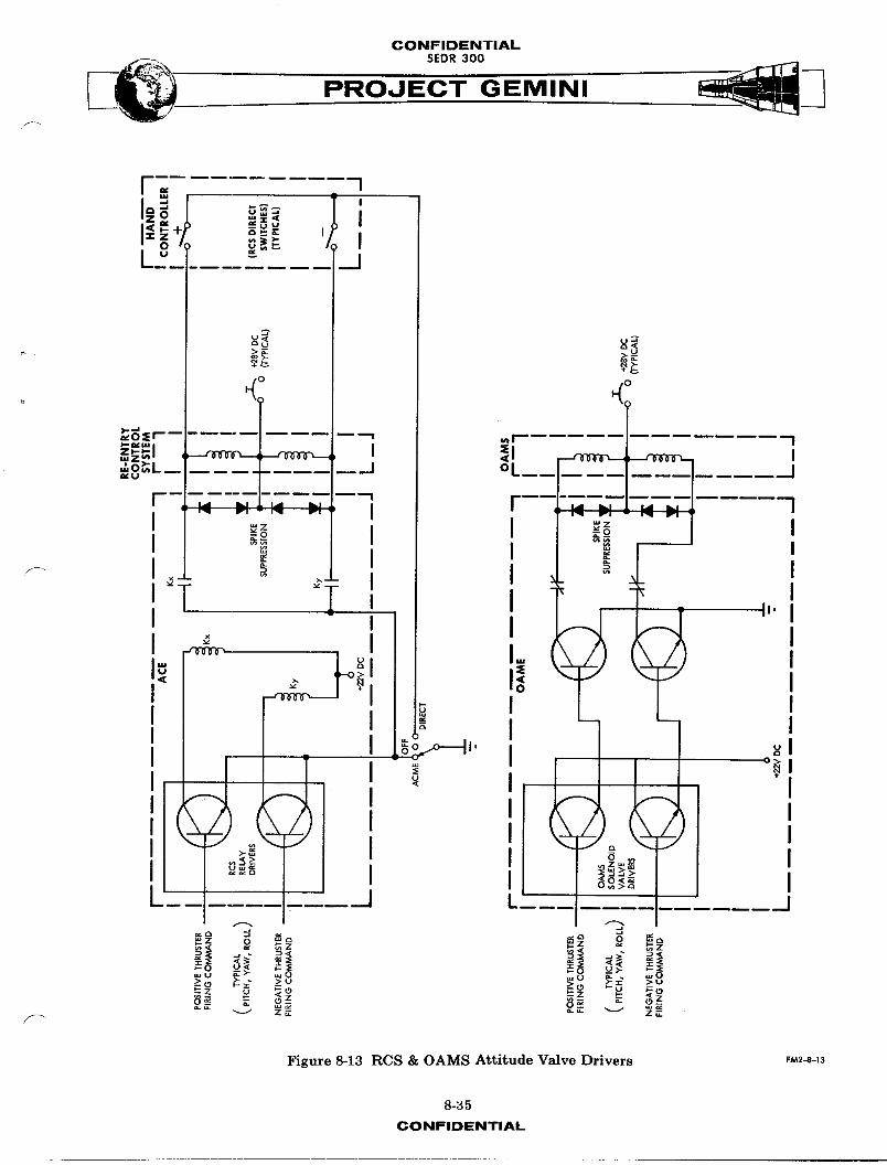
RCS Valve Drivers
The RCS solenoid valve drivers (Figure 8-13) are relays with normally open
contacts connected between the solenoid valve and the RCS ring switch and
provides a circuit ground when the switch is in the ACME position. The relays
are energized by transistor relay drivers, which conduct upon receiving thruster
firing com,Auds from the control torque logic switches or the attitude hand
controller direct switches.
ORBIT ATTITUDE A_D MAI_UVER _T,_CTRONICS (OAME)
This unit (Figure 8-4) weighs approximately 8 pounds, has a removable cover and
contains three removable module boards (2-relay boards and 1-component module
board) and fixed mounted components. These replaceable module boards in con-
junction with the fixed components function as a_titude and maneuver valve
drivers.
Functional C_eration
Attitude Control
Attitude cc._,_udsto the 0AME are either positive or negative thruster firing
co_m_uds to the solenoid valve drivers, from the control torque logic section
of ACE. (See Figure 8-13). Upon receiving comm_ud signals, the valve driver
transistors will conduct. This provides the circuit grounds to energize the
solenoid valves of the propllsion system. Zener diode spike suppression is
provided to limit the voltage generated when thruster power is interrupted.
8-34CONFIDENTIAL
CONFIDENTIALSEDR300
J= I
L 8 • _ ,
A
0 0
H
_:Er--- --'--_ _r I
.. oi ,I __o_ II _ I _- I
_- I _ I _ II°T -I I _,.II I II _ I. I
I
, ,I o_..o IJ' _I
F 'L'_ [ _ _
,- o _. _z o_" _ ._ -
_. _°_U _>- _0 _ __>,.) _£ >u .u " >u
__ _-_ "'I z_.
Figure 8-13 RCS & OAMS Attitude Valve Drivers F_2-_-_3
8-35
CONFIDENTIAL

CONFIDENTIAL
,, SEDR300 _3
PROJECT GEMINI
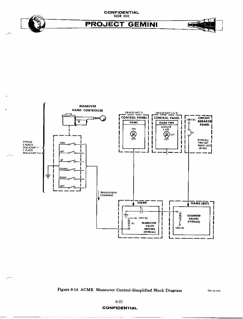
Maneuver Control
Maneuver COmmAnds to the OAME originate from either maneuver hand controller
(Figure 8-14). Translational COmmAnd sign_1-_are provided by applying a cir-
cuit ground through the proper hand controller switch, to the valve driver
relays. Upon actuation of the relay, a norm_11y open relay contact is closed.
This applies the circuit ground to the OA_S valve solenoids for thruster firing.
Conventional diode spike suppression is provided to _im_t the voltage spike
generated when thruster power is interrupted.
RATE GYRO PACKAGE
The rate gyro package (Figure 8-4) contains three rate gyros, each individu_11y
mounted and hermetic_11y sealed. The gyros are orthogo_lly mounted for rate
sensing in all three axes. The rate gyro package provides AC analog outputs,
proportional to mechanical rate inputs. Application of a glmbal torquer current,
and monitoring the spin motor synchronization, provides a check of gyro opera-
tion and pickoff output during ground checkout. Each gyro is separately
excited so that any individual gyro may be turned off, without affecting opera-
tion of the other two. Two gyro packages are provided for redundancy, and
have a total weight of approximately 8 pounds.
POWER INVERTER PACKAGE
The power inverter (Figure 8-4) converts spacecraft DC power into AC power for
use by the ACME sub-syst_q and horizon sensors. The unit weighs approximately
7 pounds and consists of the following: current and voltage regulators,
oscillator, power amplifier, output filter, regulator-controller, switching -_
8-36CONFIDENTIAL
CONFIDENTIAL
PROJECT GEMINI
MANEUVER
HAND CONTROLLER(SPACECRAFT7) (SPACECRAFT3 &4)
,_,__F_ iCONTROL'AN"'I;CON,ROL_N_!CIRCUIT
;VDC
BREAKERJ
" I J o. I Ill _T_T_ Jll I , PANELI
' 'J =b_,_,i-- I----J--_J L
_PICAL _" o'_ ISPACECP,AFT7
1 PLACE AFISPACECRAFT3 &
- _ow. _ JI ' I rL __._,,o. ___
I OAME "1' I OA_-(REE) "-1
'-L II I ! II _O,ENO,o I-- +_0c I VALVES I
MANEUVER J ITYPICAL| IVALVE
DRIVERS I 28VDC I
I (lrYPICAL) I IL ..... j
Figure8-14 ACME Maneuver Control-SimplifiedBlock Diagram F_,'1-8-14A
8-37
CONFIDENTIAL

CONFIDENTIAL
" PROJECT GEMINI
regulator and oscillator starter. The 26 VAC, 400 cps power inverter output
is supplied to the following:
a. ACE Power Supply: reference power for the choppers,
demodulators and DC biasing voltages.
b. Rate Gyros: 20 watts starting power and 16 watts z_inn_ng
power for motor and pickoff excitation.
c. Horizon Sensors : ll watts operational power, as reference
for bias voltages and pickoff excitation.
d. Attitude Hand Controller: 0.5 watts for potentiometer
excitation.
e. Telemetry: 1.O watts for demodulation reference.
f. FDI: 8.2 watts
8-38CONFIDENTIAL
CONFIDENTIAL
INERTIAL GUIDANCE SYSTEM
TABLE OF CONTENTS
TITLE PAGE
SYSTEM DESCRIPTION --......... 8-41s_ INERTIAL MEASUREMENT UNIT __ . . 8-41
AUXILIARY COMPUTER POWER UNIT . 8-41ON-BOARD COMPUTER ........ 8-49
SYSTEM OPERATION ......... 8--42PRE-LAUNCH PHASE ...... 8-43LAUNCH PHASE ............ 8-43ORBIT PHASE ............. 8-44RETROGRADE PHASE ......... 8-46RE-ENTRY ..... 8-46CONTROLS AND INDIC£TOP_ : ..... 8-47
SYSTEM UNITS ........... 8-51INERTIAL MEASUREMENT UNIT • • • 8-51AUXILIARY COMPUTER POWER UNIT . . 8-67
DIGITAL COMPUTER .......... 8-70SYSTEM DESCRIPTION ....... 8-70SYSTEM OPERATION ......... 8-74
MANUAL DATA INSERTION UNIT . . . 8-161SYSTEM DESCRIPTION ......... B-161SYSTEM OPERATION ....... 8-165
INCREMENTAL VELOCITY INDICATOR[ [ 8-170SYSTEM DESCRIPTION ......... 8-170SYSTEM OPERATION ....... 8-1"/2
8-39
CONFIDENTIAL
CONFIDENTIAL
SEO.OOPROJECT GEMINI
E DISPLAY INDICATOR
INSERTION UNIT
_ON1J_OLSAND, NDICATOP_ J j _/ _ , :,1/ IPLATFORM CONTROLS AND INDICATORS I
/
INCREMENTAL VELOCIIY INDICATOR
FLIGHT DIRECTOR CONTROLLER
INSTRUMENTPANELS // -- _ \_
\
//
/ Is
/¢,__-\ ,
j/_ i INERTIAL PLATFORMGUIDANCE SYSTEM POWER SUPPLY
\ , J SYSTEM ELECTRONICSI
AUXILIARY COMPUTER POWER UNIT
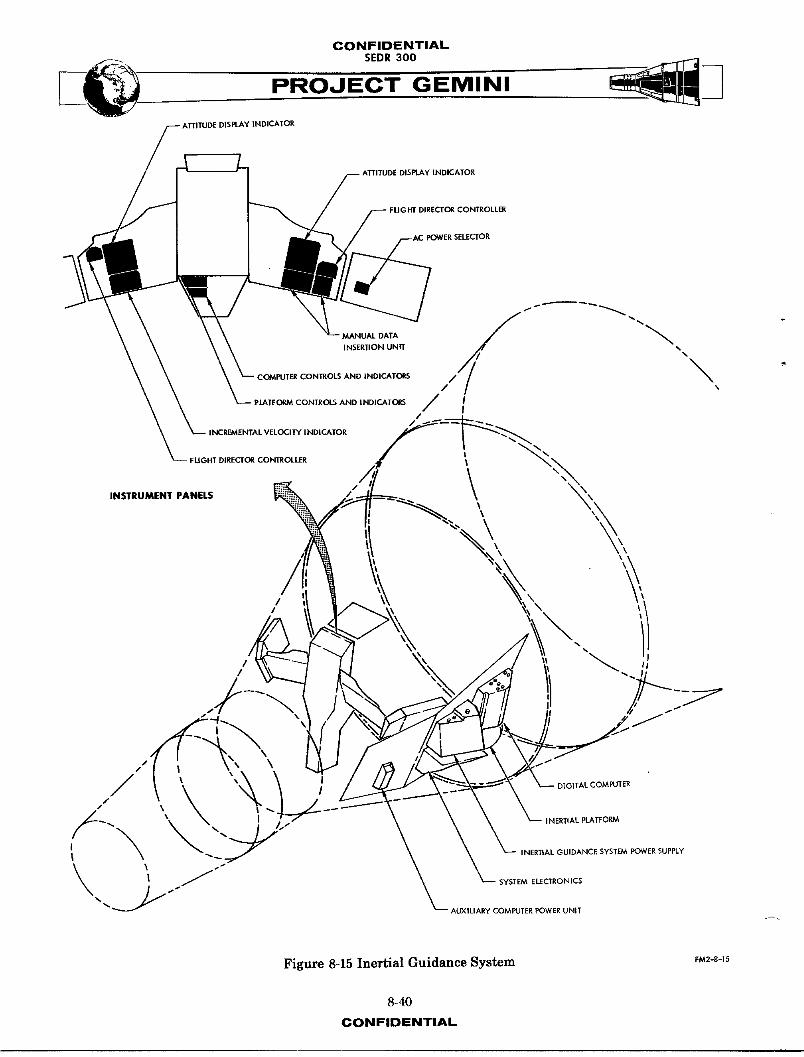
Figure 8-15 Inertial Guidance System EM2-S-_S
8-40
CONFIDENTIAL
CONFIDENTIAL
SEDR300
PROJEEMINI
INERTIAL GUIDANCE SYST_
SYST_ DESCRIPTION
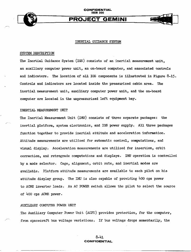
The Inertial Guidance System (IGS) consists of an inertial measurement unit,
an auxiliary computer power unit, an on-board computer, and associated montrols
and indicators. The location of all IGS components is illustrated in Figure 8-15.
Controls and indicators are located inside the pressurized cabin area. The
inertial measurement unit, auxiliary computer power unit, and the on-board
coml_Ater are located in the unpressurized left equipment bay.
INERTIAL MEASUREMENT UNIT
The Inertial Measurement Unit (IMU) consists of three separate packages: the
inertial platform, system electronics, and IGS power supply. _11_ three packages
function together to provide inertial attitude and acceleration information.
Attitude measurements are utilized for automatic control, computations, and
visual display. Acceleration measurements are utilized for insertion, orbit
correction, and retrograde computations and displays. IMU operation is controlled
by a mode selector. Cage, alignment, orbit rate, and inertial modes are
available. Platform attitude measurements are available to each pilot on his
attitude display group. The IMU is also capable of providing 400 cps power
to ACME inverter loads. An AC POWER switch allows the pilot to select the source
of 400 cps ACME power.
AUXILIARY COMPUTER POWER UNIT
The Auxiliary Computer Power Unit (ACPU) provides protection, for the computer,
from spacecraft bus voltage variations. If bus voltage drops momentarily, the
CONWIDENTIAL
CONFIDENTIAL
f;_... SEDR300 _._
ACPU supplies temporary computer power. If bus voltage remains depressed, the
computer is automatically turned off. The ACPU is activated by the computer
power switch.
ON-BOARD COMPUTER
The On-Board Computer (OBC) provides the necessary parameter storage and compu-
tation facilities for guidance and control. Computations are utilized for
insertion, orbit correction and re-entry guidance. A mode selector determines
the type of computations to be performed. A START switch allows the astronaut
to initiate certain computations at his discretion. The COMP light indicates
the start and completion of a computation. A MALF light indicates the operational
status of the computer and a RESET switch provides the capability to reset the
computer in case of temporary malfunctions. A Manual Data Insertion Unit (MDIU)
allows the pilot to communicate directly with the computer. Specific parameters
can be inserted, read out, or cleared from the computer memory. An Incremental
Velocity Indicator (IVI) displays velocity changes. Changes can be measured
or computed, depending on computer mode.
SYST_OPERATION
Operation of the IGS is dependent on mission phase. Components of IGS are
utilized from pre-launch through re-entryphases. Landing phase is not controlS-
able and therefore no IGS functions are required. The computer and platform
each have mode selectors and can perform independent functions. However, when
computations are to be made concerning attitude or acceleration, the two units
must be used together.
8-h-2CONFIDENTIAL
CONFIDENTIAL
__ SEDR300
PROJECT GEMINI
PRE-LAUNCH PHASE
Pre-lsunch phase consists of the last 150 minutes before launch. This phase
is utilized to warm-up, check-out, program, and align IGS equipment. After
warm-up, the computer performs a series of self checks to insure proper operation.
Information not previously progrA_ed but essential to the mission is now fed
into the computer. AGE equipment utilizes accelerometer outputs to Align
IM_ pitch and yaw gimbals with the local vertical. The roll gimbal is aligned
to the desired launch azimuth by AGE equipment.
LAUNCH PHASE
Launch phase starts at lift-off and lasts throt_jainsertion. During the first
and second stage boost portion of launch, the guidance functions are performed
by the booster autopilot. If the primary booster guidance system should fail,
a Malfunction Detection System (MDS) provides automatic switchover to back-up
(Gemini) guidance. Back-up ascent guidance can also be selected manuA11y, at
the discretion of the co_and pilot. The computer has been programmed with
launch parameters and the IMU provides continuous inertial reference for back-
up ascent guidance. To minimize launch error_ the computer is updated by ground
stations throughout the launch phase. In the back-up ascent guidance operation,
the computer provides steering and booster cut-off co-.._ndsto the secondary
booster autopilot. The computer also supplies attitude error signals to the
flight director needles. The IMU provides inertial attitude reference to the
attitude ball. At Second Stage Engine Cut-Off (SSECO), guidance control is
switched from booster to Gemini IGS. The computer starts insertion computa-
tions at SSECO and, at spacecraft separation, displays the incremental velocity
8-43CONFIDENTIAL
CONFIDENTIALSEDR 300
change required for insertion in the desired orbit. When the required velocity
change appears,the command pilot will accelerate the spacecraft to insertion
velocity. During acceleration,the IMU supplies attitude and velocity changes
to the computer. The computer continuously subtracts measured acceleration
from required acceleration on the display. When insertion has been achieved,
the incremental velocity indication will be zero along all three axes.
ORBIT PHASE
Orbit phase consists of that time between insertion and the start of retrograde
sequence. If the IGS is not to be used for long periods of time,it can be
turned off to conserve power. If the platform has been turned off, it should
be warmed up in the CAGE mode approximately one hour before critical alignment.
The computer should be turned on in the pre-launch mode and allowed 20 seconds
for self checks before changing modes. IGS operation,during orbit,is divided
into three separate operations. The initial part of orbit is used for check
out and alignment. The major part of orbit is used to perform experiments and
orbital maneuvers and the final portion is used in preparation for retrograde
and re-entry.
Check-Out & Ali6nment
I,,,ediatelyafter orbit confirmation the spacecraft is maneuvered to sm/ll end
forward and the platform aligned with the horizon sensors. Horizon sensor
outputs are used to align pitch and roll gimbals in the platform. The yaw
gimbal is aligned through gyrocompassing techniques using the roll gyro output.
This output is used to align the yaw gyro to the orbit plane. The platform
8-44CONFIDENTIAL

CONFIDENTIAL
PROJECT GEMINI/
alignment will be maintained by the horizon sensors as long as SEF or BEF modes
are used. ORB RATE mode is used when maneuvers are to be performed. ORB RATE
is an inertially free mode except for the pitch gyro which is torqued at approxi-
mately four degrees per minute (orbit rate). The purpose of torquing the pitch
gyro is to maintain a horizontal attitude with respect to the earth. If ORB
RATE mode is used for long periods of time,drift errors can occur. To eliminate
errors due to gyro drift, the mode is switched back to SEF or BEF for automatic
alignment.
Orbital Maneuvers
IGS operation during orbital maneuvers consists of performing inertial measure-
f_ meritsand maneuver computations. Platform alignment is performed in SEF or
BEF mode prior to initiating a maneuver. The computer START button is pressed
to initiate computation of velocity changes and computed velocity requirements
are automatically displayed on the IVI. Flight director needles are referenced
to the computer during maneuvers and indicate the attitude in which transla-
tional thrust should be applied. When the spacecraft is in the correct attitude
for a maneuver, all of the incremental velocity indication _]_ be along the
forgard-aft translational axis. As thrust is applied, the IMU supplies the
computer with attitude and acceleration information to continuously update the
IVI indications. When the maneuver has been completed, the platform can be
realigned to the horizon sensors.
Preparation for Retrograde & Re-Entr_
Preparation for retrograde and re-entry is performed in the last hour before
retrograde sequence. If the IMUhas been turned off, it must be turned on one
8-h-5CONFIDENTIAL

CONFIDENTIAL
PROJECT GEMINI
hour before retrograde. (The gyros and aceelerometers require approximately
one half hour to warm up and another half hour is required for stabilization
and alignment.) The attitude ball will indicate when platform gimbals are
aligned to spacecraft axes. At this time,the spacecraft is maneuvered to
Blunt End Forward (BEF) and the platform aligned with the horizon sensors.
The platform rpmAins in BEF mode to maintain alignment until retrograde sequence.
The computer retrograde initial conditions are checked and if necessary updated
by either ground tracking stations or the pilot. Preparation for retrograde
and re-entry is completed by placing the computer in R_2Y mode.
RETROGRADE PHASE
Retrograde phase starts at five minutes prior to retrofire on spacecraft 3 and 4
(256 seconds prior to retrofire on spacecraft 7) and ends approximately twenty-
five seconds after retrofire initiation. At the start of retrograde phase, a
minus sixteen degree bias is placed on the pitch needle of the attitude indica-
tor. At time-to-go to retrograde minus 30 seconds (TR-30 seconds),the platform
is placed in ORB RATE mode. While the retro-rockets are firing (approximately
22 seconds), the acceleration and attitude are monitored by the IMU and supplied
to the computer for use in re-entry computations. The computer starts compu-
tations for re-entry at retrofire. Computations are based on the time of retro-
fire, inertial position and attitude, and retrograde acceleration.
RE-ENTRY PHASE
Re-entry phase starts immediately after the retro rockets stop firing and lasts
until drogue chute deployment. After retrograde,a 180° roll maneuver is per- _-_
formed and pitch attitude is adjusted so that the horizon can be used as a
8-46CONFiDENTiAL
CONFIDENTIAL
PROJECT GEMINI
visual attitude reference. The spacecraft attitude is controlled by visual
observation of the horizon until the computer commands a re-entry attitude at
approximately 400,000 feet. The spacecraft is then controlled to null the flight
director needles. Flight director needles are referenced to the computer during
re-entry. The I_.IUsupplies inertial attitude and acceleration signals to the
computer. Bank angle commands are computed and displayed on the roll needle
for down range and cross range error correction. The bank angle commands last
between 0 and 500 seconds depending on the amount of down range and cross range
error. Pitch and yaw needles display down range and cross range errors respec-
tively. Upon completion of the bank angle commands (spacecraft on target), a
roll rate of 15 degrees per second is commanded by the computer. At approxi-
'_ mately 80,000 feet,the computer commands an attitude suitable for drogue chute
deployment. Immediately after drogue deployment the IGS equipment is turned off.
CONTROLS AND INDICATORS
Attitude Display Group
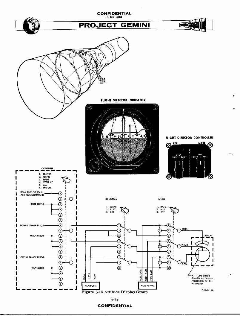
The Attitude Display Group (ADG) (Figure 8-16) consists of a Flight Director
Indicator (FDI) a Flight Director ControS1er (FDC) and their associated ampli-
fiers. Three types of displays (attitude, attitude rate, and ADG power off)
are provided by the FDI. A three axis sphere with 360 degrees of freedom in
each axis continuously displays attitude information. The sphere is slaved
to the inertial platform gimbals and always indicates platform attitude. Three
needle type indicators display attitude and/or attitude rate information as
selected by the pilot. Information displayed on the needles is provided by
the computer, platform and rate gyros. A scale selector is included in the
8-47CONFIDENTIAL
CONFIDENTIALSEDR 300
FLIGHT DIRECTOR INDICATOR
FLIGHT DIRECTOR CONTROLLER
ILEF MODE
COMPUTER
I. RE-ENT
2. TDPRE3. RNDZ4. CTCH UP
5. ASC I6. PRE-LN I
ROLL RATE OR ROLL __,(_ IIATTITUDE COMMANDI
(_:i ( REFERENCE MODE
ROLL E_OR _ I "_ "_
I 1. CMPT I. RATEI 2. PLAT 2. MIXi 3. RDR 3. ATTII ! I
(_ I I I
, ,, ,,o--_OE.,ORO' I _ _; 'O._ROLL
r',*CH,RROR, I T _ ':_l T _', __IO'SPLA¥
i _'_ -_.-1| .__ ,'_._ I'_'_ pITCH _ I
®,, , _'_'_ L__',,'-" I_,CROSS RANGE ERROR (_ : r"---L'_ - _.._! _i _ ) I
:r ATTITUDE SPHERE
_ _ SLAVED TO GIMBAL
I_ ....... (_) -- -- ] 'L ] _ _ >" _OI_'TIcONRMSOF THE6A
Fi ure ;-16 Attitude Display Group
8-48
CONFIDENTIAL
CONFIDENTIALSEDR300
FDI to allow the selection of HI or LO scale indications on the needles. The
FDC is used to select the source and type of display on the needles. Figure 8-16
includes a simplified schematic of the FDC switching and indicates the source
and type of signal available. Since the computer is capable of producing differ-
ent types of signals, the computer mode selector is included in the schematic.
The FDC reference selector determines the source of display information. The
FDC mode selector determines the type of signal displayed.
Manual Data Insertion Unit
The Manual Data Insertion Unit (MDIU) consists of a ten digit keyboard and a
seven digit register. The MDIU allows the pilot to communicate directly with
the on-board computer. Provision is made to enter, cancel or read out informa-
tion. The keyboard is used to address a specific location in the computer
and set up coded messages for insertion. The first two keys that are pressed
address the computer memory word location and the next five set up a coded
message. Keys are pressed in a "most significant bit first" order. Negative
values are inserted by making the first number of the message a 9. The 9 then
represents a minus sign and not a number. The seven digit register is used
to monitor addresses and messages entered into or read out of the computer.
Push button switches are included on the register panel to READ OUT, CL_R, and
ENTER the messages. Information can also be inserted in the computer by the
ground tracking stations which have digital command system capabilities.
S
8-49CONFIDENTIAL
CONFIDENTIALSEDR 300
PROJEC---'T--GEM IN I
Incremental Velocit_r Indicator
The Incremental Velocity Indicator (M) provides a display of computed velocity
increments required for, or resulting from, a specific maneuver. The M is
controlled through the on-board computer. Displays are utilized for orbit
insertion, orbit correction and retrograde. Velocity increments are provided
along each of the spacecraft translational axis. Controls are included to
,_nually insert plus or minus velocity increments into the IVI.
Computer Controls
Computer controls consist of: a COMPUTER mode selector, a START switch, a
COMP light, a MALF light, a RESET switch, and an ON-OFF switch. The COMPUTER
mode selector is a rotary switch which selects the type of computations to be --
performed. Modes of operation correspond to the mission phase in which they
are utilized. The COMP light indicates when the computer is running through
its program and provides a means of checking computer sequencing. The START
switch is utilized for manual initiation of certain computations.
NOTE
The START switch must be operated in con-
junction with the computer mode selector
and the COMP light.
The MALE light indicates when a malfunction has occurred and the RESET switch
resets the computer malfunction indicator. The RESET switch is only capable
of resetting the computer for momentary malfunctions. An ON-OFF switch controls
power to the computer and the at_iliary computer power unit.
8-50CONFIDENTIAL
CONFIDENTIAL
_. SEOR300
PROJECT GEMINI
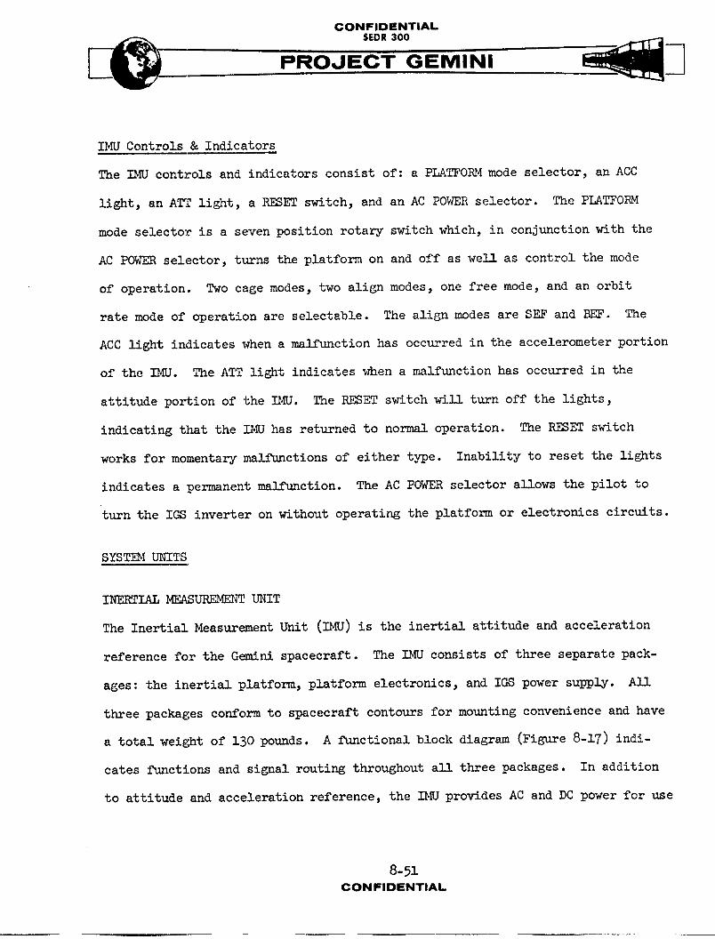
IMU Controls & Indicators
The IMU controls and indicators consist of: a PLATFORM mode selector, an ACC
light, an ATT light, a RESET switch, and an AC POWER selector. The PLATFORM
mode selector is a seven position rotary switch which, in conjunction with the
AC POWER selector, turns the platform on and off as well as control the mode
of operation. Two cage modes, two align modes, one free mode, and an orbit
rate mode of operation are seleetable. The align modes are SEF and BEF. The
ACC light indicates when a malfunction has occurred in the accelerometer portion
of the IMU. The ATT light indicates when a malfunction has occurred in the
attitude portion of the IMU. The RESET switch will turn off the lights,
indicating that the IS,[Uhas returned to normal operation. The RESET switch
works for momentary malfunctions of either type. Inability to reset the lights
indicates a permanent malfunction. The AC POWER selector allows the pilot to
turn the IGS inverter on without operating the platform or electronics circuits.
SYSTEM UNITS
INERTIAL MEAS_ UNIT
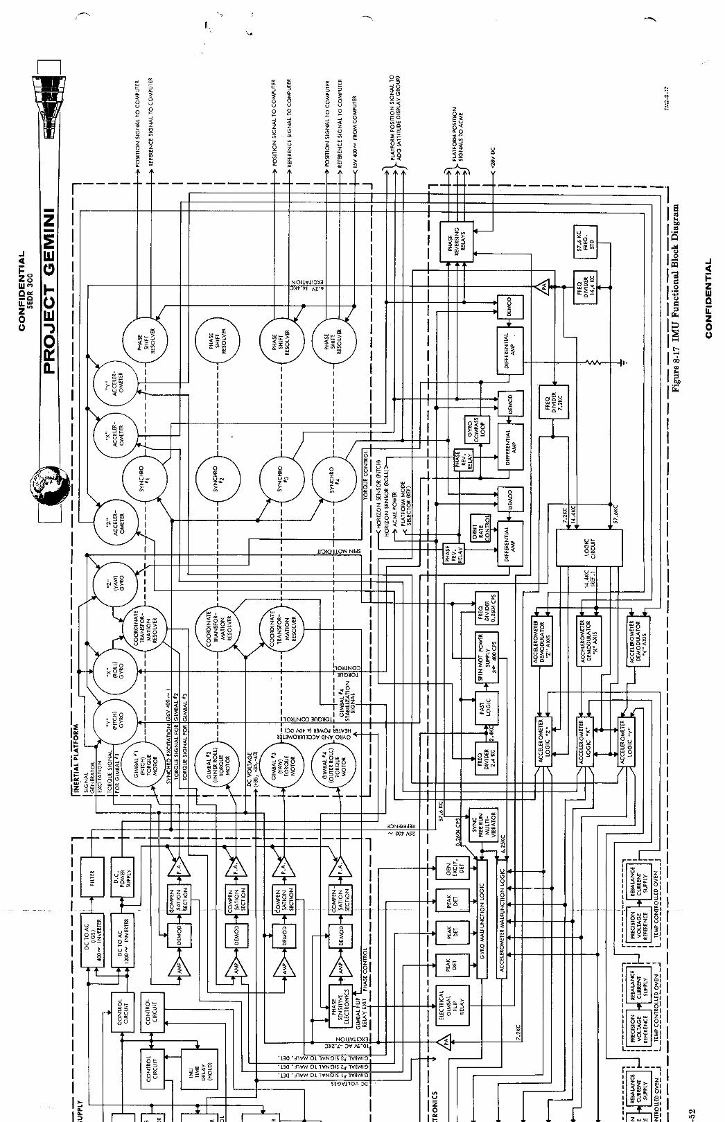
The Inertial Measurement Unit (IMU) is the inertial attitude and acceleration
reference for the G_m_ni spacecraft. The IMU consists of three separate pack-
ages: the inertial platform, platform electronics, and IGS power supply. All
three packages conform to spacecraft contours for mounting convenience and have
a total weight of 130 pounds. A functional block diagram (Figure 8-17) indi-
cates functions and signal routing throughout all three packages. In addition
to attitude and acceleration reference, the I_J provides AC and DC power for use
8-51CONFIDENTIAL
1 II
![[_]"II _ I I
I I
II
t
I

CONFIDENTIAL
PROJ'-E-C"T GEMINI
in other units of guidance and control. The platform and electronics packages
are mounted on cold plates to prevent overheating.
NOTE
References to x, y, and z attitude and
translational axes pertain to inertial
guidance only and should not be confused
with structural coordinate axes.
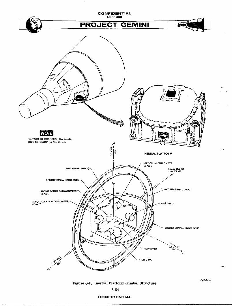
Inertial Platform
The inertial platform (Figure 8-18) is a four gimbal assembly containing three
miniature integrating gyros and three pendulous accelerometers. Gimbals allow
the gyro mounting frame (pitch block) to rP_n in a fixed attitude while the
housing moves freely about them. Major components of the platform are: a
housing, glmbal structure, torque motors, gimbal angle syaehros, resolvers,
gyros and accelerometers. The gimbals from inside to outside are: pitch,
inner roll, yaw and outer roll. All gimbals, except inner roll, have 360
degrees of freedom. The inner roll gimbal is limited to plus and minus 15
degrees. Two roll gimbals are used to eliminate the possibility of gimbal
lock. Gimbal lock can occur on a three gimbal structure when an attitude of 0
degrees yaw, 0 degrees pitch, and 90 degrees roll exists. At this timer he roll
and yaw gimbals are in the same plane and the yaw gimbal cannot move about its
axis (gimbal lock). In the four gimbal platform, an angle of 90 degrees is
8-53CON FIDENTIAL
CONFIDENTIAL
PROJECT GEMINI
NOTE
plATFORM gO-ORDINATES - xp, YP, Zp.BODY CO-ORDINATES-XB, YB, Zb.
_ _ INERTIALPLATFORMI
"ICAL ACCEI.EROMETER(Z AXLS)
FIRST GI/_BAL (PITCH) _FOURTH GIMBAL
(YAw)ALONG COURSE ACCELF_ROMIEEER_\.0(AXIS)
A(_OSS COLJ
(Y AXLS)
(INNER ROLL)
FM2-8-18
Figure 8-18 [ne_ia| Platform Gimba] Structure
8-54
CONFIDENTIAL

CONFIDENTIAL
B
maintained between the inner roll and yaw gimbals thus preventing gimbal lock.
The inertial components are mounted in the innermost g_mbal casting (pitch
block) for rigidity and shielding from thermal effects. The gyros and asso-
ciated servo loops maintain the pitch block in a fixed relationship with the
reference coordinate system. The accelerometer input axes are aligned with the
three mutually perpendicular axes of the pitch block. Two sealed optical
quality windows are provided in the housing for alignment and testing. Both
windows provide optical access to an alignment cube located on the stable element.
S_stemElectronics
The system electronics package contains the circuitry necessaryfor operation
f- of the IMU. Circuits are provided for gyro torque control, timing logic, spin
motor power, accererometer logic, accelerometer rebalanee, and m,l_unction
detection. Relays provide remote mode control of the above circuits.
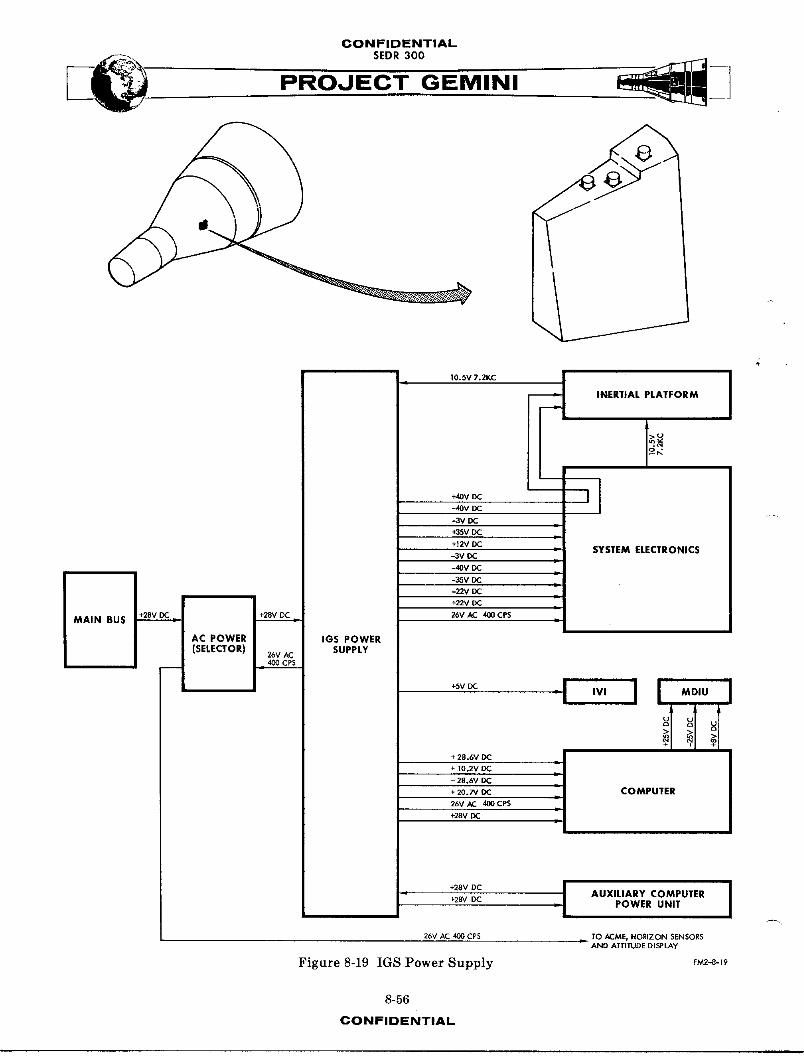
IGS Powe r Supply
The IGS power supply (Figure 8-19) contains gimbal control electronics and the
static power supply unit. Gimbal control electronics drive torque motors in
the platform. Separate control circuits are provided for each gimbal. The
static power supply provides the electrical power for the IMU, OBC, ACPU, MDIU,
IVI, ACME, and horizon sensors. Figure 8-19 indicates the types of power
available and the units to which they are supplied.
8-55CONFIDENTIAL
CONFIDENTIAL
PROJECT GEMINI
t 10. SV 7.2KC _ I I
INERTIAL PLATFORM
+40VDCMOV _
-3V IX: "
÷aSV Dt2
+t2V _• SYSTEMELECTRONICS
-3V IX:
-40V DC
-35V DCL
-22V DC
+22V DC
MAIN BUS +2e_.__vv_ +28V DC -- 26V AC 400 CPS
AC POWER lOS POWER
(SELECTOR) 26vAC SUPPLY-- 400 CPS
÷svIX: "l IVI I
>_
+ 28.6V DC |
I+ IO.2V DC _.- 28.6V DC
+ 20.7V IX: = COMPUTER
÷28V26V AC 400 CPSDC :l
+28vOC ! AUXILIARY COMPUTER
÷28'v' DC - J POWER UNIT
26VAC400CPS L TOACME, HORIZON SENSORS_o At.rUDEo,_,_¥
Figure 8-19 IGS Power Supply _-8-_9
8-56
CONFIDENTIAL

CONFIDENTIAL
__ SEDR300
FOJEC-'T-GEMINI
Attitude Measurement
Attitude measurements are made from inertial platform glmb-1_ and reflect the
difference between spacecraft and gimbal attitudes. Platform g_mbals are
maintained in essentiaS_ya fixed inertial attltude by gimbalcontrol elec-
tronlcs. As the spacecraft moves about the attitude axes, friction transfers
some of the movement to platform gimbals. Three miniature gyros are used to
sense minute gimbal attitude changes. When gyros sense a change in attitude,
they produce a signal proportional to the attitude error. Gyro outputs are
then used by gimbal control circuits to drive gimbals to their original inertial
attitude. Gimbalpositions, relative to the spacecraft, are measured by synchros
and resolvers. Synchro outputs are provided for attitude display, automatic
attitude control, and gyro alignment. Two types of resolvers, phase shift
and coordinate transformation, are used. Phase shift resolvers provide g_mbal
angle information to the computer. Coordinate transformation resolvers provide
attitude signals for gimbal control purposes.
Modes of Operation
Seven modes of operation are selectable by the pilot. The modes, in order
of switeh position are: OFF, CAGE, SEF, ORB RATE, _, CAGE, and FR_. The
CAGE position is used for IMUwarm-up and to align the platform gimbals with
spacecraft body axes. Platform gimbals are caged prior to fine alignment
with the horizon sensors. In the cage mode, gimbals are torqued by synehro
outputs until a null is obtained on the synchro. When synchro outputs reach
n,ll, torquing stops and the gimbals are aligned with spacecraft axes. SEF
8-5?CONFIDENTIAL

CONFIDENTIALSEDR 300
(small end forward) mode is used to align the platform with the horizon sensors
when the spacecraft is flying small end forward. Horizon sensor pitch and roll
outputs are compared with synchro outputs and the difference used to torque
gimbals. When synchro and horizon sensor outputs are balanced, the gimbals are
aligned to earth local vertical. A gyro compass loop aligns the yaw gimbald
with the orbit plane.
NOTE
If horizon sensors lose track during either
S_ or BEF alignment modes, the platform is
automatic_!ly switched to orbit rate mode.
ORB RATE (orbit rate) mode is used to maintain attitude reference during space-
craft maneuvers. Orbit rate mode is inertially free except for the pitch
gyro. The pitch gyro is torqued at approximately four degrees per minute to
maintain a horizontal attitude with respect to the earth. If orbit rate mode
is used for long periods of time, drift can cause excessive errors in the plat-
form. SEF (blunt end forward) mode is the same as SEF except that relays
reverse the phase of horizon sensor inputs. The second CAGE mode allows the
platform to be caged in blunt end forward without switching back through other
modes. FRk_. mode is used during launch and re-entry phases. Free mode is
completely inertial and the only torquing employed is for drift compensation.
NOTE
Free mode is selected automatic_11y by
the Sequential System at retrofire.
8-58CONFIDENTIAL

CONFIDENTIAL
,,o.,ooPROJECT GEMINI
Gimbal Control Circuits
Four separate servo loops provide gimbal attitude control. Figure 8-17 illus-
trates the signal flow through all four loops. Gyro signal generator outputs
are used either directly or through resolvers as the reference for gimbal
control. Both phase and amplitude of signal generator outputs are functions
of gimbal attitude. Gimbal number one (pitch) is controlled directly by the
pitch gyro output. Error signals produced bythe pitch gyro are amplified,
demodulated, and compensated, then used to drive the pitch gimbal torque motor.
The first amplifier raises the signal to the level suitable for demodulation.
After amplification, the signal is demodulated to remove the 7.2 KC carrier.
A compensation section keeps the signal within the rate characteristics necessaryzf
for loop stability. When the signal is properly conditioned by the compen-
sation section, it goes to a power amplifier. The power amplifier supplies
the current required to drive gimbal torque motors. Torque motors then drive
gimbals maintaining gyro outputs at, or very near, _l].
Roll and yaw servo loops utilize resolvers to correlate gimbal angles with
gyro outputs. Inner ro]] and yaw gimbals are controlled by a coordinate trans-
formation resolver mounted on the pitch gimbal. When the spacecraft is at any
pitch attitude other than 0 or 180 degrees, some roll motion is sensed by the
yaw gyro and some yawmotion is sensed by the roll gyro. The amount of roll
motion sensed by the yaw gyro is proportional to the pitch gimbal angle. The
resolver, mounted on the pitch gimbal, coordinates roll and yaw gyro output with
pitch gimbal angle. Resolver output is then conditioned in the same manner as
in the pitch servo loop to drive inner roll and yaw gimbals.
8-59CONFIDENTIAL

CONFIDENTIAL
PROJEC GEMINI
The outer roll gimbal is servo driven from the inner roll gimbal resolver. A
coordinate transformation resolver, mounted on the inner roll gimbsl, monitors
the angle between inner roll and yaw gimb_1_. If the angle is anything other
than 90 degrees, an error signal is produced by the resolver. The error signal
is conditioned in the same manner as in the pitch servo loop to drive the outer
roll gimbal. One additional circuit (phase sensitive electronics) is included
in the outer roll servo loop. The outer roll gimbal torque motor is mounted
on the platform housing and moves about the stable element with the spacecraft.
As the spacecraft moves through 90 degrees in yaw, the direction that the outer
roll gimbal torque motor must rotate, to compensate for spacecraft roll, reverses.
Phase sensitive electronics and a resolver provide the phase reversal necessary
for control. The resolver is used to measure rotation of the yaw gimbal about
the yaw axis. As the gimbal rotates through 90 degrees in yaw, the resolver
output changes phase. Resolver output is compared to a reference phase by the
phase sensitive electronics. Nhen the resolver output changes phase, the
torque motor drive signal is reversed.
Pre-Launch A1ig_ment
The IMU is the inertial reference for back-up ascent guidance and must, therefore,
be aligned for that lmnm!_se. The platform is aligned to local vertical and the
launch azimuth. Platform X and Y accelerometers are the reference for local
vertical alignment. When the platform is aligned to the local vertical, X
and Y aceelerometers are level and cannot sense any acceleration due to gravity.
If any acceleration is sensed, the platform is not properly aligned and must be
torqued until no error signal exists. The accelerometer output is used by AGE
8-60
CONFIDENTIAL
CONFIDENTIAL
--_ SEDR 300 _____
" " PROJECT GEMINI
equiy=ent to generate torque signals for the gyros. When the gyro is torqued,
it produces an error signal which i_ used to align the gimbal. The outer roll
gimbal synchro output is compared with a signal representing the launch azimuth
by AGE equipment. The error signal is conditioned by AGE equipment and applied
to the yaw gyro torque generator. The yaw gyro signal generator then produces
a signal proportional to the input torque. Gyro output is coordinated by a
resolver mounted on the pitch gimbal. Since the spacecraft is in a 90 degree
pitch up attitude, essentially all of the yaw gyro output is transferred to
roll gimbal control electronics. The electronics drive the roll gimbals until
no error exists between synchro output and the AGE reference signal. When no
error signal exists, the platform is aligned to the launch azimuth.
Orbit AI_gnment
_1_gnment of the platform in orbit is accomplished by referencing it to the
horizon sensors. Placing the platform mode selector in SEF or BEF position
will reference it to the horizon sensors. Pitch and roll horizon sensor out-
puts are compared with platform pitch and outer rolI synchro outputs. Differen-
tial amplifiers produce torque control signals, proportional to the difference
between sensor and synchro outputs. Torque control signals are used to drive
pitch and roll gyro torque generators. Gyro signal generator outputs are then
used by gimbal control electronics to drive platform gimbals. When synchro
and horizon sensor outputs balance, the pitch and roll gimbals are aligned to
the local vertical. The yaw gimbal is AS_gned to the orbit plane through a
8yro compass loop. If yaw errors exist, the roll gyro _]I sense a component
f-
8-61CONFIDENTIAL

CONFIDENTIALSEDR300
" PROJECT GEMINI
of orbit rate. The orbit rate component in the roll gyro output is used, through
a gyro compass loop,to torque the yaw gyro. Yaw gyro output is then used by
gimbal control electronics to drive the yaw gimbal. When the roll gyro no
longer senses a component of orbit rate, the yaw gimbal is aligned to the
orbit plane. ASI three gimbals are now aligned and will remain aligned as long
as SEF or B_F modes are used. The pitch gyro w_11 be continuously torqued
(at the orbit rate) to maintain a horizontal attitude.
NOTE
If horizon sensors lose track while the
platform is in SEF or BEF modes, the
platform is automatically switched to
orbit rate mode.
Orbit Rate Circuit
The orbit rate circuit is used to maintain alignment to the local vertical
during orbit maneuvers. Local vertical cannot be provided by horizon sensors
during maneuvers because they willlose track. To maintain a horizontal
attitude with no external reference, the pitch gyro is torqued at approxi-
mately four degrees per minute. The torque represents the spacecraft orbit rate.
Torque is obtained byplacing a DC bias on the output of the pitch differential
amplifier. The bias drives the pitch gyro torquer at the orbit rate. Orbit
rate bias is adjustable and can be set to match orbits of various altitudes.
8-62CONFIDENTIAL
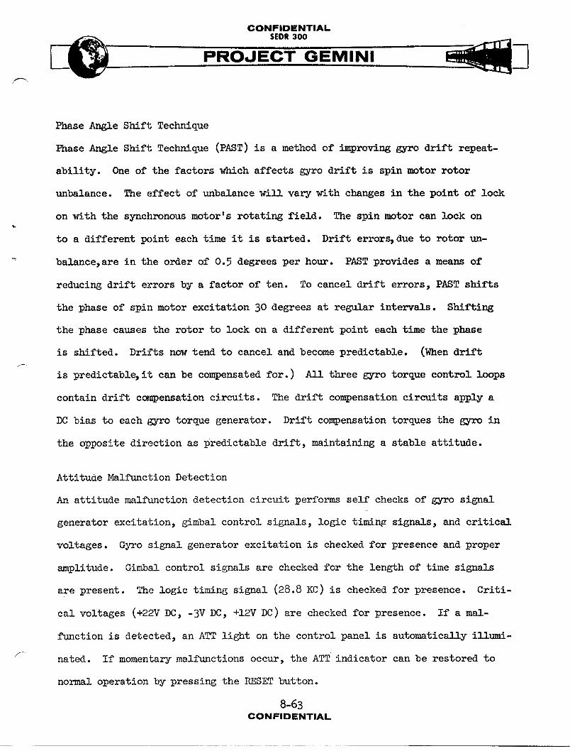
CONFIDENTIAL
SEDR300
PROJEC-T- GEMINI
Phase Angle Shift Technique
Phase Angle Shift Technique (PAST) is a method of improving gyro drift repeat-
ability. One of the factors which affects gyro drift is spin motor rotor
unbalance. The effect of unbalance will vary with changes in the point of lock
on with the synchronous motor's rotating field. The spin motor can lock on
to a different point each time it is started. Drift errors, due to rotor un-
balance, are in the order of 0.5 degrees per hour. PAST provides a mean_ of
reducing drift errors by a factor of ten. To cancel drift errors, PAST shifts
the phase of spin motor excitation 30 degrees at regular intervals. Shifting
the phase causes the rotor to lock on a different point each time the phase
is shifted. Drifts now tend to cancel and become predictable. (When drift
is predictable, it can be compensated for. ) All three gyro torque control loops
contain drift compensation circuits. The drift compensation circuits apply a
DC bias to each gyro torque generator. Drift compensation torques the gyro in
the opposite direction as predictable drift, maintaining a stable attitude.
Attitude Malfunction Detection
An attitude malfunction detection circuit performs self checks of gyro signal
generator excitation, gimbal control signals, logic timing signals, and critical
voltages. Gyro signal generator excitation is checked for presence and proper
amplitude. Gimbal control signals are checked for the length of time signs!a
are present. The logic timing signal (28.8 KC) is checked for presence. Criti-
cal voltages (+22VDC, -3VDC, +12V DC) are checked for presence. If a mal-
function is detected, an ATT light on the control panel is automatically illumi-
nated. If momentary malfunctions occur, the ATT indicator can be restored to
normal operation by pressing the RESET button.
8-63CONFIDENTIAL
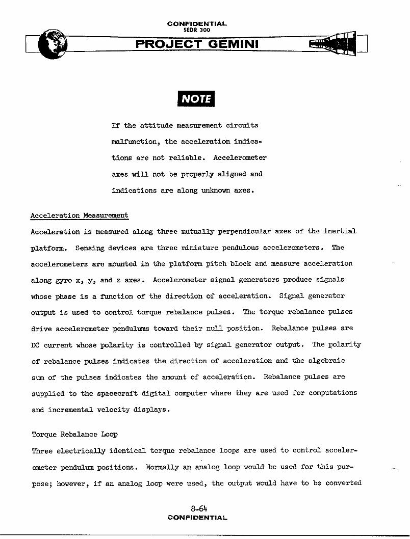
CONFIDENTIAL
PROJE-C"T-G EMINI
NOTE i
If the attitude measurement circuits
malfunction, the acceleration indica-
tions are not reliable. Accelerometer
axes will not be properly aligned and
indications are along unknown axes.
Acceleration Measurement
Acceleration is measured along three mutually perpendicular axes of the inertial
platform. Sensing devices are three miniature pendulous accelerometers. The
accelerometers are mounted in the platform pitch block and measure acceleration
along gyro x, y, and z axes. Accelerometer signal generators produce signals
whose phase is a function of the direction of acceleration. Signal generator
output is used to control torque rebalance pulses. The torque rebalance pulses
drive accelerometer pendul_,ms toward their n_11 position. Rebalanee pulses are
DC current whose polarity is controlled by signal generator output. The polarity
of rebalance pulses indicates the direction of acceleration and the algebraic
sum of the pulses indicates the amount of acceleration. Rebalance pulses are
supplied to the spacecraft digital computer where they are used for computations
and incremental velocity displays.
Torque Rebalance Loop
Three electrically identical torque rebalance loops are used to control aeceler-
ometer pendulum positions. Normally an analog loop would be used for this pur- _
pose; however, if an analog loop were used, the output would have to be converted
8-64CONFIDENTIAL

GONFIDENTIAL
__ SEDR300
PROJECMINI
to digital form for use in the computer. To e_m_nate the need for an analog
to digital converter, a pulse rebalance loop is used. Short duration 184
milliampere DC current pulses drive the accelerometer pendulum in one direction
until it passes through nt_]1. Pulses are applied at the rate of 3.6 KC. When
the pendulum passes through n_]I, signal generator output changes phase. The
signal generator output is demodulated to determine the direction of the pen-
dulum from n,11. Demodulator output is used by logic circuits to control the
polarity of rebalance pulses. If acceleration is being sensed, there will be
more p1_laes of one polarity than the other. If no acceleration is being sensed,
the number of pulses of each polarity will be equal. In addition to contro11_ug
the polarity of rebalance pulses, logic circuits set up precision timing of thef-
Im_ses. Precision frequency inputs from the timing circuits are the basis for
rebalance pulse timing. Precise timing is essential because the amount of pendulum
torque depends on the length of the current p_!1_e. AII p-1_es are precisely the
same duration and amplitude, therefore total torque is dependent only on the al-
gebraic sum of the applied pulses. Each time a reb_!_nce pulse is applied to
the accelerometer torquer, a pulse is _!ao provided to the computer. Algebraic
m_mm_tion of the rebalance pulses is performed by the computer.
Pulse Rebalance Current Supply
A pnlse rebalance current supply provides the required current for _orque rebal-
ante. Since acceleration measurements are based on the number of torque l_1_es
it is essential that all pulses be as near identical as possible. To maintain
a stable current, a negative feedback circuit is employed. The supply output
is passed through a precision resistor and the voltage drop across the resistor is
8-65CONFIDENTIAL

CONFIDENTIAL
PROJECT GEMINI
compared to a precision voltage reference. Errors detected by the comparison
are used in the feedback circuit to correct any deviations in current. To
further enhance stability, both the current supply and the precision voltage
reference are housed in a temperature controlled oven.
Accelerometer Dither
A pendulous accelerometer, unlike a gyro, has an inherent mass unbalance. The
mass unbalance is necessary to obtain the pendulum action. Due to the unbalance,
perfect flotation of the pendulous gimbal cannot be achieved and consequently
pressure is present on the gimbal bearing. To minimize the stiction effect,
caused by bearing friction, a low amplitude oscil s_tion is imposed on the
gimbal. The oscillation (dither) prevents the gimbal from resting on its
bearing long enough to cause stiction. To obtain gimbal oscillation, two signals
are required: a lO0 cps dither signal and a DC field current. The DC field
current is superimposed on the signal generator excitation and creates a mag-
netic field around the gimbal. The lOO cps dither is applied to a separate (mod-
ulator) coil. The dither signal beats against the DC field, causing the gimbal
to oscillate up and down. The dither motion is not around the output axis and
consequently no motion is sensed by the signal generator.
Accelerometer Malfunction Detection
An acceleration malfunction detection circuit performs self checks of incre-
mental velocity pulses and critical voltage. Incremental velocity p_S_es from
each of the three axes are checked for presence. If pulses are absent longer
than 0.35 seconds, it indicates that a flip flop did not reset between set pulses.
8-66CON FIDENTIAL

CONFIDENTIAL
PROJECT GEMINI
The critical voltage (+I2VDC) is checked for presence. If a malfunction is
detected, an ACC light on the control panel is automatically illuminated.
If momentary mal:_unctions occur, the accelerometer mnleunction circuit can be
restored to normal operation by pressing the RESET button.
NOTE
Malfunction of the accelerometer circuits
does not affect attitude measurements.
AUXILIARY COMPUTER POWERUNIT
The Auxiliary Computer Power Unit (ACPU) is used in conjunction with the IGS
_ power supply to maintain the correct DC voltages at the computer. The com-
puter cannot function properly on low voltage, either as a transient or a de-
pression. Abnormal voltages can cause permanent changes in the co_uter memory.
Three types of circuits are provided in the ACPUto prevent a low voltage condi-
tion at the computer. The first circuit is a transient sense and auxiliary power
control circuit. The second circuit is a low voltage sense and power control
circuit and the third is auxiliary power. The ACPU is turned on and off with
the computer power switch.
Transient Sense Circuit
The transient sense circuit is designed to sense and correct transient low
voltage conditions. A series type transistor voltage regulator holds auxiliary
power off the line as long as IGS power supply, computer voltage regulator, voltage
is normal. If regulator voltage momentarily drops below 17.7 volts, the transient
sense circuit detects the drop and turns on the series re_11_tor. The regulator
8-67CONFIDENTIAL.

CONFIDENTIAL
PROJEC-T GEMINI
then places auxiliary power on the line and maintains voltage at the desired
level.
Low Voltage Sense Circuit
A low voltage sense circuit prevents the computer from operating on low voltage.
When the computer is turned on, the low voltage sense circuit insures that
spacecraft bus voltage is above 21 volts before allowing power to be applied
to the computer. If the computer is already on when a low voltage condition
occurs, the transient sense circuit w_l] maintain normal voltage for i00 mi]]_-
seconds. If spacecraft bus voltage is not back to nor_l after i00 m_11_seconds,
the low voltage sense circuit initiates a controlled shutdown of the computer.
Computer power is contro! led through contacts of a relay in the low voltage
sense circuit. When the low voltage sense circuit detects a voltage depression,
it de-energizes the relay. Contacts of the relay turn off the computer in a
manner identical with the computer power switch. When the low voltage sense
circuit turns off the co_puter, it also breaks power to all ACPU circuits except
low voltage sense. If power were not broken to the transient sense circuit,
it would attempt to __ntain normal voltage at the computer. In atte,_ting
to maintain normal voltage, the auxiliary power capability would be exceeded.
Auxiliar_ Power
Auxiliary power consists of a battery and a trickle charger. A 0.5 ampere-hour
nickle cadmium battery is used to supply computer power during spacecraft bus low
voltage transients. The battery w_ll supply up to 9.8 amperes for periods of I00
mi11_seconds or less. A trickle charger is provided to maintain a f_11 charge
on the battery. The charger consists of a transistor oscillator, transformer,
8-68
CONFIDENTIAL

CONFIDENTIAL
PROJECT GEMINI
and rectifier. The oscillator changes spacecraft bus voltage to AC. The AC
voltage is then stepped up with a transformer and changed back to DC by a _11
wave diode rectifier. Rectifier output is then applied, through a current
limiting resistor, to the battery. The resistor limits charging current to
25mi1_amperes. Provision is included to charge the battery from an external
source if desired.
8-69CONFIDENTIAL

CONFIDENTIAL
SEDR300PROJECT GEMINI
DIGITAL COMPUTER
SYST]_4DESCRIPTION
General
The Digital Computer, hereinafter referred to as the computer, is a binary,
fixed-point, stored-program, general-purpose computer, used to guide the
spacecraft. The computer is 18.90 inches high, 14.50 inches wide, and 22.75
inches deep. It weighs 58.98 pounds. External views of the computer are shown
on Figure 8-20. The major exter_1 characteristics are summarized in the
accompanying legend.
Using inputs from other spacecraft systems along with a stored program, the
computer performs the computations necessary to develop the guidance and control
outputs required by the spacecraft during the Pre-Launch and Re-Entry phases
of the mission. In addition, the computer provides back-up guidance for the
launch vehicle during Ascent.
Inputs and Outputs
The computer is interfaced with the Inertial Platform, Platform Electronics,
Inertial Guidance System (IGS) Power Supply, Auxiliary Computer Power Unit (ACPU),
Manual Data Insertion Unit (MDIU), Time Reference System (TRS), Digital Command
System (DCS), Attitude Display, Attitude Control and Maneuver Electronics (ACME),
Titan Autopilot, Pilots' Control and Display Panel (PCDP), Incremental Velocity
Indicator (M), Instrumentation System (IS), and Aerospace Ground Equipment (AGE).
In co-nection with these interfaces, the computer inputs and outputs include the
following:
8-70CONFIDENTIAl.

CONFIDENTIALSEDR 300
'/'_ LEGEND
IIEM NO._E NCLAI_RE
Q MOUNTING ACCESS COVER
Q CONNECTO_ 24
Q CO N NI:CTC_ J5
(_ CO_IN'ECTOR J7
Q CONNECTOR J3
Q CONNECTOR J2
O CONNECtOR Jl
(_ CONNECTOR J6
C_ MOUNTING ACC]ESSCOVER
(_ MOUN[ING ACCESS COVER
MOUNTING ACCESS COVER
ELAPSED TIME INDICATOR
CONNECTOR ACCESS COVER
(_ RELIEF VALVE
C_ MOUNTIIx_G ACCESS COVER
(_ HANDLE
MOUNTING ACCESS COVER
(_ IDENTIFICATION PLA1E
(_ (_ MAiN ACCESS COVER
(_ BUS BAR ACCESS COVER
(_ BUS BAR ACCESS COVER
RELIEFVALVE
Figure 8-20 Digital Computer FM2-8-20
8-71
CONFIDENTIAL

CONFIDIENTIAL
SEDit300PROJECT GEMINI
Inputs
40 discrete
3 incremental velocity
3 gimbal angle
2 high-speed data (500 kc)
i low-speed data (3-57 kc) _
1 low-speed data (182 cps)
1 input and readback (99 words)
6 DC power (5 regulated, 1 unregulated)
1 AC power (regulated)
t uts
30 discrete
3 steering come,and
3 incremental velocity
1 decimal display (7 digits)
1 telemetry (21 digital data words)
1 low-speed data (3.57 kc)
1 low-speed data (18R cps)
3 DC power (reg_lated)
1 AC power (regulated, filtered)
O_erational Characteristics
The major operational characteristics of the computer are as follows:
L
Binary, fixed-point, stored-program, general-purpose
8-72
CONFIDENTIAL
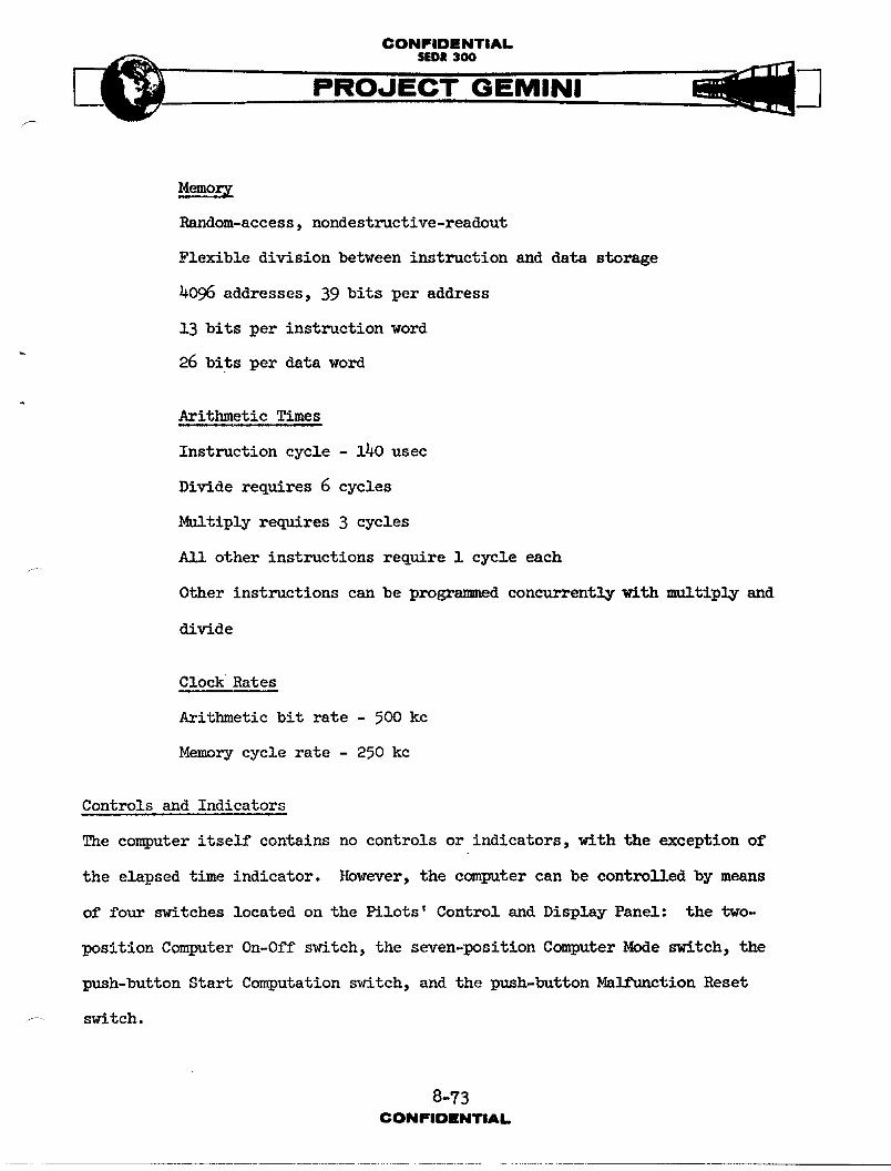
CONFIDENTIAl.
.__ SEDR3OOPROJECT GEMINI
MemolV
Random-access, nondestructive-readout
Flexible division between instruction and data storage
4096 addresses, 39 bits per address
i3 bits per instruction word
" 26 bits per data word
Arithmetic Times
Instruction cycle - 140 usec
Divide requires 6 cycles
Multiply requires 3 cycles
A11 other instructions require 1 cycle each
Other instructions can be progrA-med concurrently with multiply and
divide
Clock Rates
Arithmetic bit rate - 500kc
Memory cycle rate - 250 kc
Controls and Indicators
The computer itself contains no controls or indicators, with the exception of
the elapsed time indicator. However, the computer can be controlled by means
of four switches located on the Pilots' Control and Display Panel: the two-
position Computer On-Off switch, the seven-position Computer Mode switch, the
push-button Start Computation switch, and the push-buttonM-leunction Reset
F- switch.
8-?3CONFIOENTIAL

CONFIOENTIAL
SYST_I OPERATION
Power
The computer receives the AC and DC power required for its operation from the
Inertial Guidance System (IC_) Power Supply. The re_1_ted DC power supplied
to the computer is buffered in the ICeSPower Supply in a manner that eliminates
any loss in regulation due to transients that occur in the spacecraft prime _
power source. Actlm1_power interruptions and depressions are buffered by the
ICeSPower Supply and the Auxiliary Computer Power Unit. The power inputs re-
ceived from the IGS Power Supply are as fo!lnws:
(a) 26 VAC and return
(b) +28 VDC filtered and return
(c) +27.2 VDC and return
(d) -27.2 VDC and return
(e) +20 VDC and return
(f) +9-3 VDC and return
The application of all power is controlled by the Computer On-Off switch on the
Pilots' Control and Display Panel. When the switch is turned on, the computer
elapsed time indicator starts operating and a power control signal is supplied
to the IGS Power Supply by the computer. This signal causes power to be trans-
ferred to the com_uter. When the switch is turned off, the computer elapsed
tlme indicator stops operating and the power control signal is terminated to
remove power from the computer.
8-7CONFIOIENTIAL
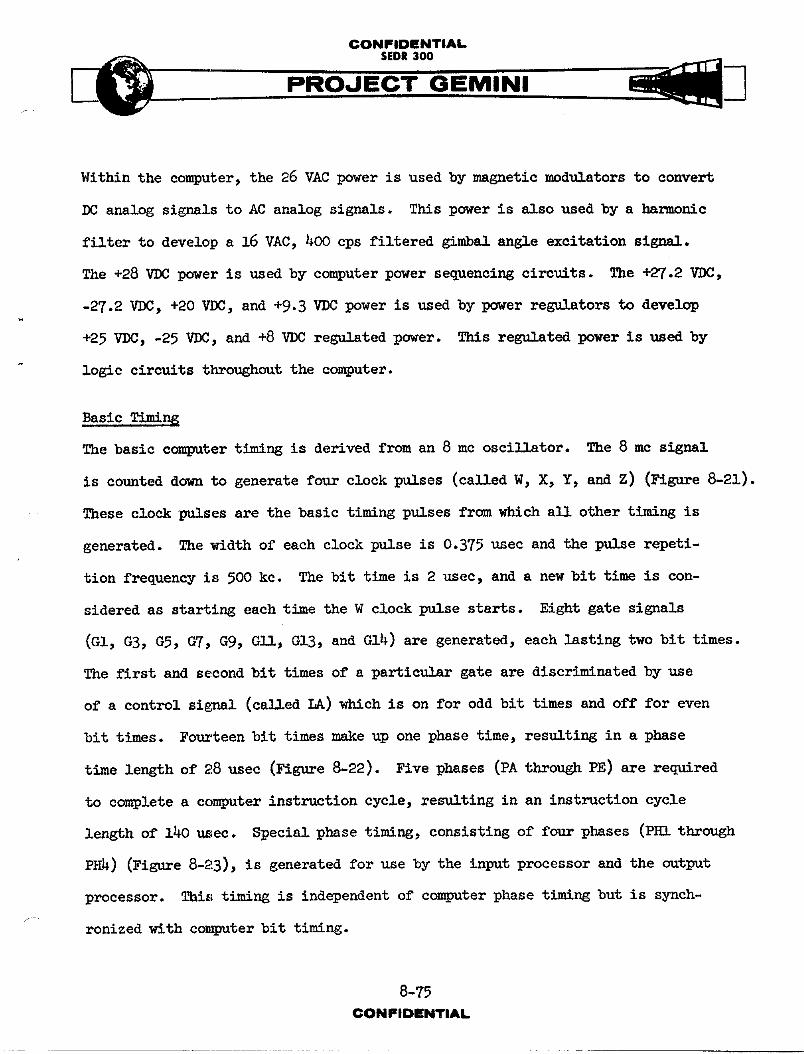
CONFIDENTIAL
SEDR300
Within the computer, the 26 VAC power is used by magnetic modulators to convert
DC analog signals to AC analog signals. This power is also used by a harmonic
filter to develop a 16 VAC, _00 eps filtered gimbal angle excitation sig--1.
The +28 VDC power is used by computer power sequencing circuits. The +27.2 VDC,
-27.2 VDC, +20 VDC, and +9.3 VDC power is used by power regulators to develop
+25 VDC, -25 VDC, and +8 VDC regulated power. This regulated power is used by
logic circuits throughout the computer.
Basic Timin_
The basic computer timing is derived from an 8 mc oscillator. The 8 mc signal
is counted down to generate four clock pulses (ca}led W, X, Y, and Z) (Figure 8-21).
These clock _1_es are the basic timing pulses from which all other timing is
generated. The width of each clock pulse is 0.375 usec and the pulse repeti-
tion frequency is 500 kc. The bit time is 2 usec, and a new bit time is con-
sidered as starting each time the W clock pulse starts. Eight gate signals
(GI, GB, GS, GT, G9, GII, GIB, and GI4) are generated, each lasting two bit times.
The first and second bit times of a particular gate are discriminated by use
of a control signal (called LA) which is on for odd bit times and off for even
bit times. Fourteen bit times make up one phase time, resulting in a phase
time length of 28 usec (Figure 8-22). Five phases (PA through PE) are required
to complete a computer instruction cycle, resulting in an instruction cycle
length of 140 _ec. Special phase timing, consisting of four phases (PHI through
PHi) (Figure 8-23), is generated for use by the input processor and the output
processor. This timing is independent of computer phase t_m_ng but is synch-/
ronized with computer bit timing.
8-75CONFIDENTIAL
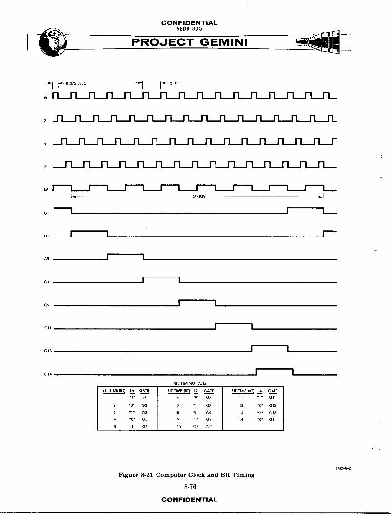
CONFIDENTIAL
s o,ooPROJECT GEMINI
--IF"°'_°_ -I I"_wn _ n n n n n n n n n n n n n_
x_n_n n n n n n n n n n n run n rL
__n n n n n n n n n n n n rL_nn r
z n_n n_n n n n n n n n n n n_n
I" _usEc _ I
o1 I I I
o3 I I I
o_ I I
o_ I I
o, I I
o1, I I
o,3 I I
o,, I I
I "1" G1 6 "0" G7 11 "1" Gll
2 "0" G3 7 "1" G7 12 "0" G13
3 "1" G3 8 "0" G9 13 "1" G13
4 "0" G5 9 "1" G9 14 "0" G1
5 "1 " G5 10 "0" G 11
FM2-8-21
Figure 8-21 Computer Clock and Bit Timing
8-76
CONFIDENTIAL
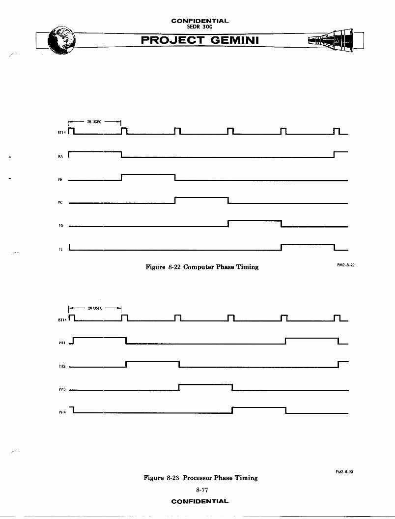
CONFIDENTIAL
PROJECT GEMINIF _J
_ 28 USEC • J
_T,_n n n n n rL
PAI I I
" PB I I
_c I I
_ I I
_ I I I
Figure 8-22 Computer Ph_Re Timing F/_-_-zz
_ 28 USEC L J
_,,_n n n n n n_
_., -I i I L
_._ I I F
P._ I N
_ -1 I I
F/V_.-B-23
Figure 8-23 Processor Phase Timing
8-77
CONFIDENTIAL

CONIFIDENTIAL
5EDR300
PROJECT GEMINI
Memory"
The computer memory is a random-access, coincldent-current, ferrlte array with
nondestructive readout. The basic storage element is a two-hole ferrite core.
The nondestructive read property m_kes it possible to read or write serially
or in series-parallel, thereby _11owing operation with a serial arithmetic unit
without a separate buffer register. The memory array can store 4096 words, or
159,744 bits. All memory words of 39 bits are divided into three syllables of
13 bits each. Data words (25 bits and a sign) are normally stored in the
first two syllables, and instruction words (13 bits) are intermixed in all three
syllables. Once the spacecraft has been removed from the hangar area, it is
not possible to modify the third syllable of any memory word. L_m_ted modifi-
cation of stored data in syllables 0 and 1 can be accomplished at the launch
site through interface with the MAnual Data Insertion Unit or the Digital
Command System.
As shown on Figure 8-24, the memory is a 64 x 64 x 39 bit array of nondestructive
readout elements. Physically, it consists of a stack of 39 planes (stacked
in the Z dimension), with each plane consisting of a 64 x 64 array of cores.
The memory is logically subdivided into smaller parts to increase the program
storage efficiency. The Z dimension is divided into three syllables (SYL 0
through SYL 2), with each syllable consisting of 13 bits. The X-Y plane is
divided into 16 sectors (SEC OO through SEC 07, and SEC lO through SEC 17),
with sector 17 being defined as the residual sector.
A memory word is defined as the 39 bits along the Z dimension and is located
at one of the 4096 possible X-Y grid positions. An instruction word or co,mmnd
requires 13 bits, and is coded in either syllable O, l, or 2 of a memory word.
8-78CONFIOINTIAI.
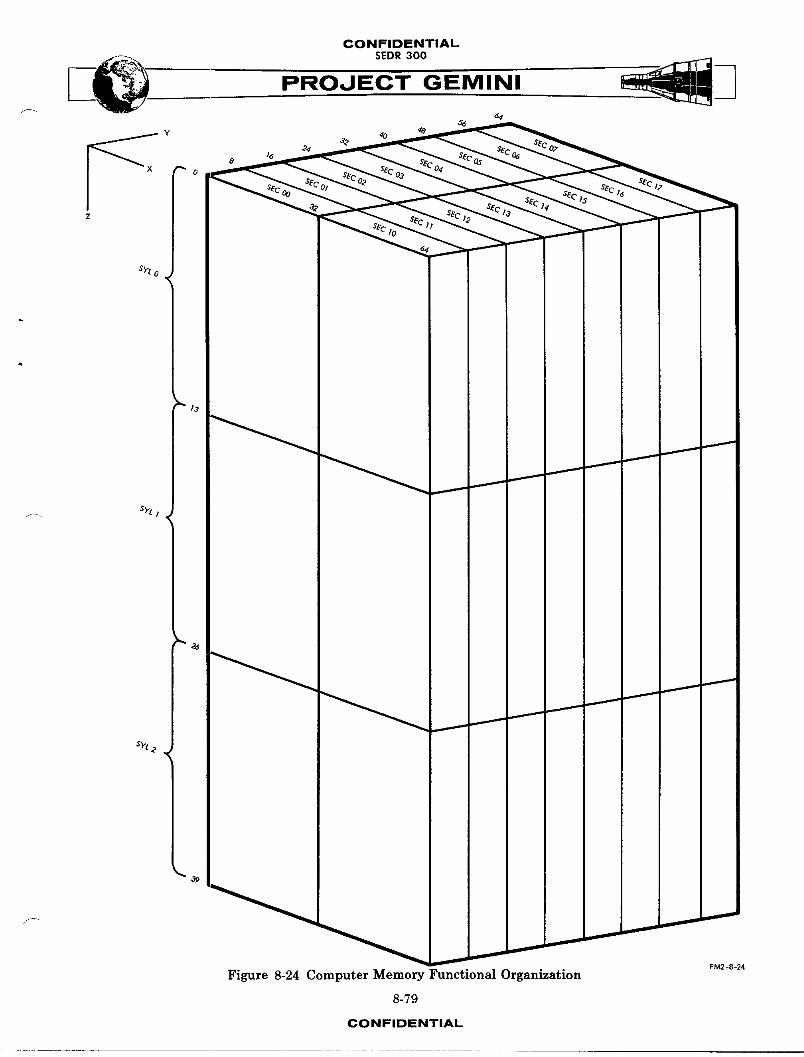
CONFIDENTIALSEDR 300
sPt o
I
t3
sPL /
&
3_
,_ _ ......a...._ _
FM2-8-24
Figure 8-24 Computer Memory Functional Organization
8-79
CONFIDENTIAL

CONFIDENTIAL
A data word requires 26 bits, and is always coded in sy1_bles 0 and I of a
memory word. Information stored in syllable 2 can be read as a short data word
by using a special mode of operation primarily used to check the contents of the
memory.
NOTE
The operation codes mentioned in the sub-
sequent paragraphs are described in the
Instruction and Data Words paragraph.
Instruction List
The instructions which can be executed by the computer are as follows :
0_erationCode Instruction
0000 HOP. The contents of the memory location specified
by the operand address are used to change the next
instruction address. Four bits identify the next
sector, nine bits are transferred to the instruction
address counter, two bits are used to condition the
syllable register, and one bit is used to select one
of the two data word modes.
0001 DIV (divide). The contents of the memory location
specified by the operand address are divided by the
contents of the accumulator. The 24-bit quotient is
available in the quotient delay line during the
fifth word time following the DIV.
8-8oCON_'_DZNT,At.
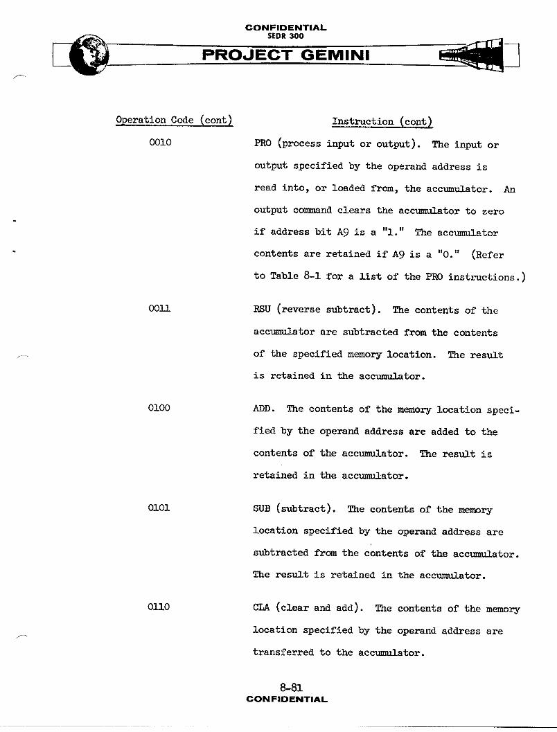
CONFIDENTIAL
___ SEDR 300
PROJECT GEMINI
OperationCode (cont_ Instruction(cont)
0010 PRO (processinput or output). The input or
output specified by the operand address is
read into, or loaded from, the accumulator. An
output comm_nd clears the accumulator to zero
if address bit A9 is a "l." The accumulator
contents are retained if A9 is a "0." (Refer
to Table 8-1 for a llst of the PRO instructions.)
OOll RSU (reversesubtract). The contentsof the
acctmmlator are subtracted from the contents
_ of the specified memory location. The result
is retained in the accumulator.
0100 ADD. The contents of the memory location speci-
fied by the operand address are added to the
contents of the accumulator. The result is
retained in the accumulator.
OlO1 SUB (subtract). The contentsof the memory
location specified by the operand address are
subtracted fremthe contents of the accumulator.
The result is retained in the accumulator.
03_10 CLA (clearand add). The contentsof the memory
location specified by the operand address aref-
transferred to the accumulator.
8-81CONFIDENTIAL
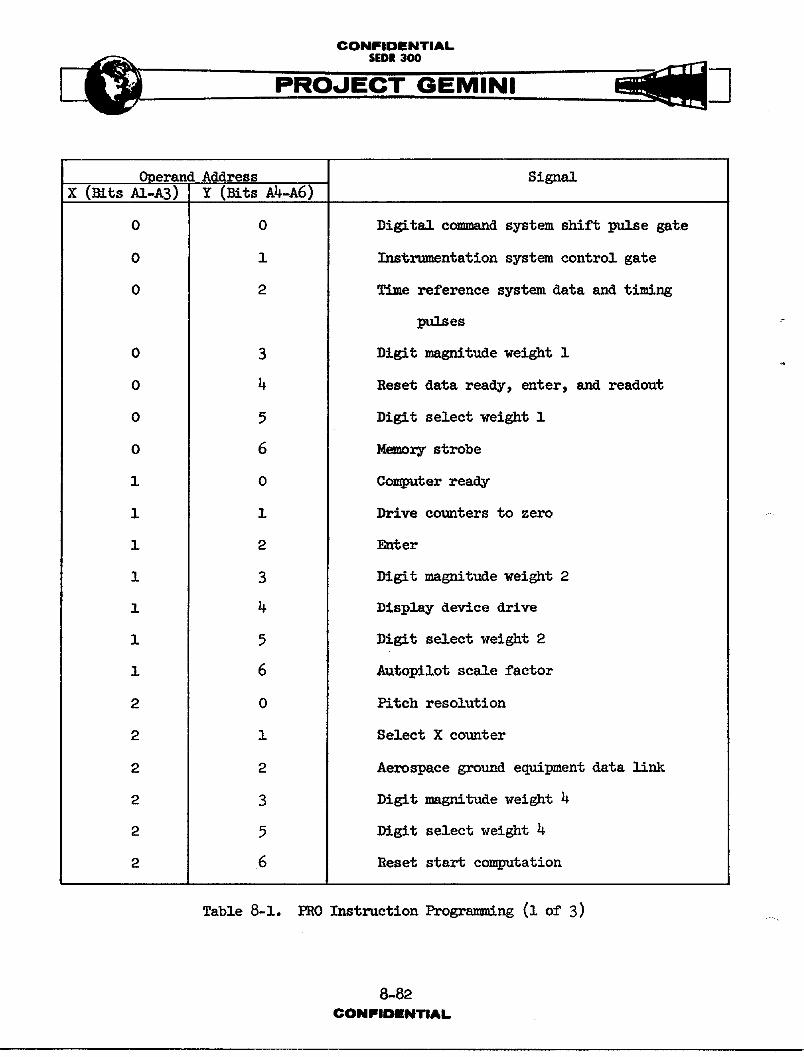
CONFIDENTIAL
[_ SEDR300
PROJECT GEMINI
Operand Address SignalX (mrs AI-A3) Y (BitsA4-A6)
0 0 Digit_l c_d system shift pulse gate
0 i Instrumentation system control gate
0 2 T_me reference system data and timing
1_,Iaes
0 3 Digit magnitude weight I
0 4 Reset data ready, enter, and readout
0 5 DigitselectweightIl
0 6 M_,_o_ry strobe
i 0 Computer ready
i i Drive counters to zero
i 2 Enter
i 3 Digitmagnitudeweight2
I 4 Display device drive
1 5 Digitselectweight2
1 6 Autopilotscalefactor
2 0 Pitch resolution
2 i Select X counter
2 2 Aerospace ground equipment data llnk
2 3 Digit magnitude weight 4
2 5 Digit select weight 4
2 6 Reset start computation
Table 8-1. PRO Instruction Programming (I of 3) ....
8-82CON FIDENTIAL

CONFIDENTIAL
Operand Address SignalX (Bits AI-A3 Y (Bits A4-A6)
3 0 Yawresolution
3 I Select Y counter
3 2 Aerospace ground equipment data clock
. 3 3 Digit magnitude weight 8
3 4 Read manual data insertion unit insert data
3 6 Reset radar ready
4 0 Roll resolution
4 i Elapsed time control and time reference
system control reset
4 3 Computer m.l_hmction
4 4 Spare
4 6 Second stage engine cutoff
5 0 Computer running
5 1 Time to startre-entrycalculationscontrol
5 2 Time to reset control
5 3 Write output processor
5 4 Read delta velocity
5 5 Input processor time
5 6 Timeto retrofirecontrol
6 3 Read pitch g_mbal
6 _ Readro11gimbal
Table 8-1. PRO Instruction Progrnmm_ng (2 of 3)
8-83CONFIDENTIAL
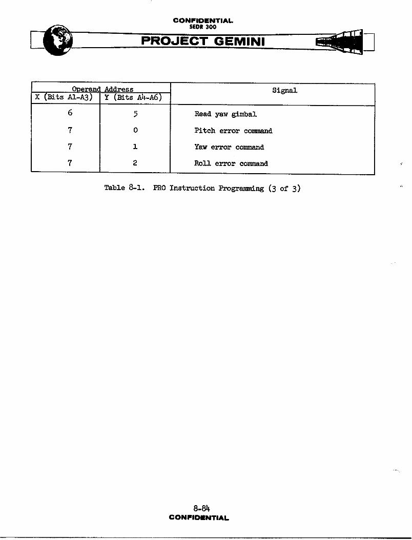
CONFIDENTIAL
Operand Address Signalx (mrs _I-AS) Y (rotsA4-A6)
6 5 Readyawgimbal
7 0 Pitch error co-_,,_._-_
7 i Yaw error co...__nd
7 2 Roll error co_.____d
Table 8-1. PRO Instruction Progrsmmting(3 of 3)
8-8_CONFIDENTIAL.
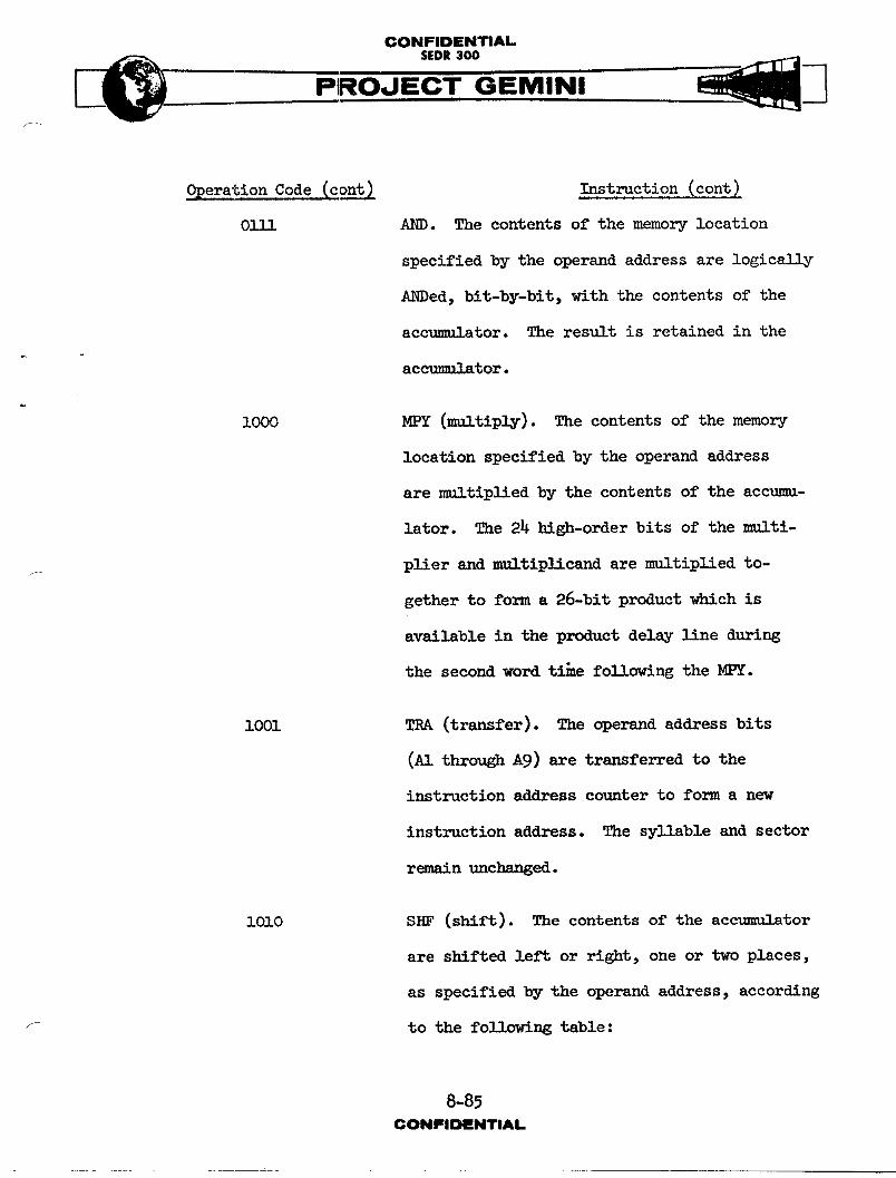
CONFIDENTIAL.SEDR300
DO. PROJECT GEMINI
OperationCode(cont) Instruction(cont1
01IS AND. The contents of the memory location
specified by the operand address are logicslly
ANDed, bit-by-bit, with the contents of the
accumulator. The result is retained in the
ac_11 _tor.
I000 MPY (multiply). The contentsof the memory
location specified by the operand address
are multiplied by the contents of the accumu-
lator. The 24 high-order bits of the multi-
plier and multiplicand are multiplied to-f
gcther to form a 26-bit product which is
available in the product delay line during
the second word ti_e following the MPY.
i001 TRA (transfer). The operand addressbits
(Al through Ag) are transferred to the
instruction address counter to form a new
instruction address. The syllable and sector
remain unchanged.
1OlO SHF (shift). The contents of the accumulator
are shifted left or right, one or two places,
as specified by the operand address, according
f tothefollowingtable:
8-85CONIFIDIINTIAL
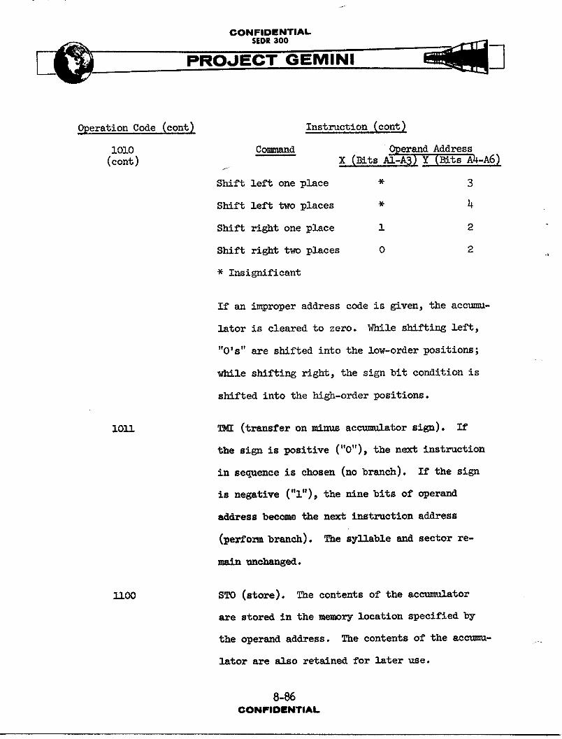
CONFIDENTIAL-SEDR 300
PRO
_OperationCode (cont) Instruction (cont)
lOlO Commm/_d O_erand Address ..(cont) X (Bits A1-A3 ) Y (Bits A4-A6)
/
Shiftleft oneplace * 3
Shiftlefttwoplaces * 4
Shiftrightone place 1 2
Shift right two places 0 2
• Insignificant
If an improper address code is given, the accumu-
lator is cleared to zero. While shifting left,
"O's" are shifted into the low-order positions;
while shifting right, the sign bit condition is
shifted into the high-order positions.
lOll TMI (transfer on minus accumulator sign). If
the sign is positive ("0"), the next instruction
in sequence is chosen (no branch). If the sign
is negative ("i"), the mine bits of operand
addmess become the next instruction address
(perform branch). The syllable and sector re-
-_- unchanged.
1100 STO (store). The contents of the accumulator
are stored in the memory location specified by
the operand address. The contents of the accumm- --
lator are also retained for later use.
8-86CONFIDENTIAL
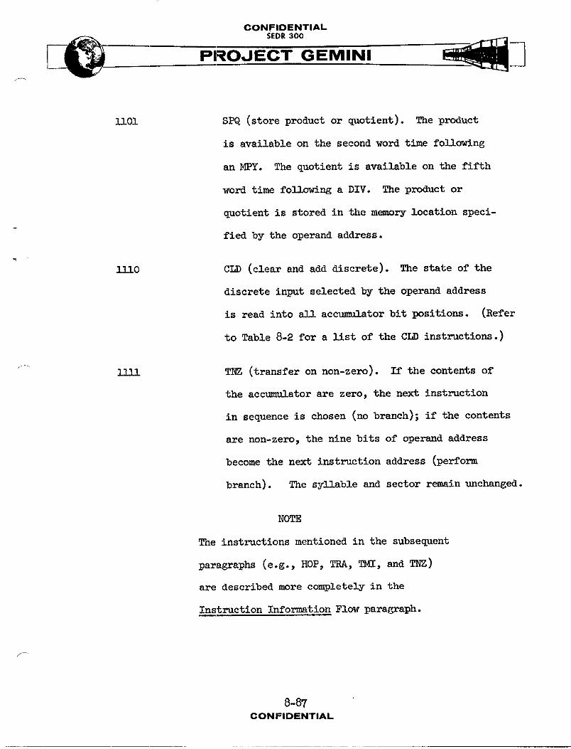
CONFIDENTIAL
PRO GEMINI
]lO1 SPQ (store product or quotient). The product
is available on the second word time following
an MPY. The quotient is available on the fifth
word time following a DIV. The product or
quotient is stored in the memory location speci-
fied by the operand address.
1110 CLD (clearand add discrete). The state of the
discrete input selected by the operand address
is read into A]] accumulator bit positions. (Refer
to Table 8-2 for a list of the CLD instructions. )
_ 111] TNZ (transfer on non-zero). If the contents of
the accumulator are zero, the next instruction
in sequence is chosen (no branch); if the contents
are non-zero, the nine bits of operand address
become the next instruction address (perform
branch). The syllable and sector rpmAin unchanged.
NOTE
The instructions mentioned in the subsequent
paragraphs (e.g., HOP, TRA, TMI, and TNZ)
are described more completely in the
Instruction Information Flow paragraph.
8-87CONFIDENTIAL
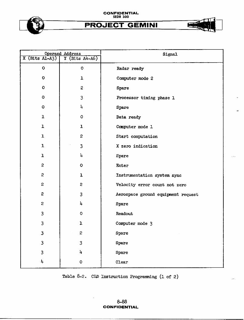
CONFIDENTIAL
PROJEC-T--GEMINI
Operand Address SignalX (BitsA1-A3) Z (BitsA4-A6)
O 0 Radarready
0 i Computer mode 2
0 2 Spare
0 3 Processor timing phase i
0 4 Spare
I 0 Dataready
i i Computermodei
i 2 Start computation
i 3 X zero indication
i 4 Spare
2 0 Enter
2 i Instrumentation system sync
2 2 Velocity error count not zero
2 3 Aerospace ground equipment request
2 4 Spare
3 0 Readout
3 i Computer mode 3
3 2 Spare
3 3 Spare
3 4 Spare
4 0 Clear
Table 8-2. CLD Instruction Programming (I of 2)
8-88CONFIDENTIAL

CONFIDENTIAL
PRO,JECT GEMINIf
OperandAddress SignalX (Bits A1-A3) Y (Bits A4-A6)
4 i Spare
4 2 Simulation mode command
4 3 Spare
4 4 Spare
5 0 Time to start re-entry calculations
5 I Spare
5 2 Y zero indication
5 3 Spare
5 4 Spare
6 0 Digital co.mmnd system ready
6 1 Fade-indiscrete
6 2 Z zero indication
6 3 Umbilical disconnect
6 4 Spare
7 0 Instrumentation system request
7 i Abort transfer
7 2 Aerospace ground equipment input data
7 3 Spare
7 4 Spare
Table 8-2. CLD Instruction Programming (2 of 2)
f
8-89CONFIDENTIAL
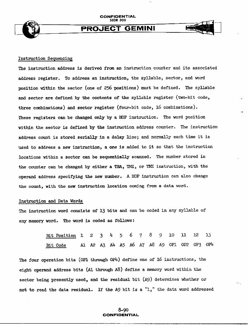
CONFIDENTIAL
SEDR 300 ____PROJEC=I" GEMINI
Instruction Sequencing
The instruction address is derived from an instruction counter and its associated
address register. To address an instruction, the syllable, sector, and word
position within the sector (one of 256 positions) must be defined. The sy11Able
and sector are defined by the contents of the syllable register (two-bit code,
three combinations) and sector register (four-bit code, 16 combinations).
These registers can be changed only by a HOP instruction. The word position
within the sector is defined by the instruction address counter. The instruction
address count is stored serially in a delay line; and normally each time it is
used to address a new instruction, a one is added to it so that the instruction
locations within a sector can be sequentially scanned. The number stored in
the counter can be changed by either a TRA, TMI, or TNZ instruction, with the
operand address specifying the new number. A HOP instruction can also change
the count, with the new instruction location coming from a data word.
Instruction and Data Words
The instruction word consists of I3 bits and can be coded in any syllable of
any memory word. The word is coded as follows :
Bit Position i 2 3 4 5 6 7 8 9 i0 Ii 12 13
Bit Code A1 A2 AB A4 A5 A6 A7 A8 A9 0P1 01>2 0PB 0P4
The four operation bits (OP1 through OP4) define one of 16 instructions, the
eight operand address bits (A1 through A8) define a memory word within the
sector being presently used, and the residual bit (Ag) determines whether orJ_
not to read the data residual. If the A9 bit is a "l," the data word addressed
8-9oCONFIDENTIAL
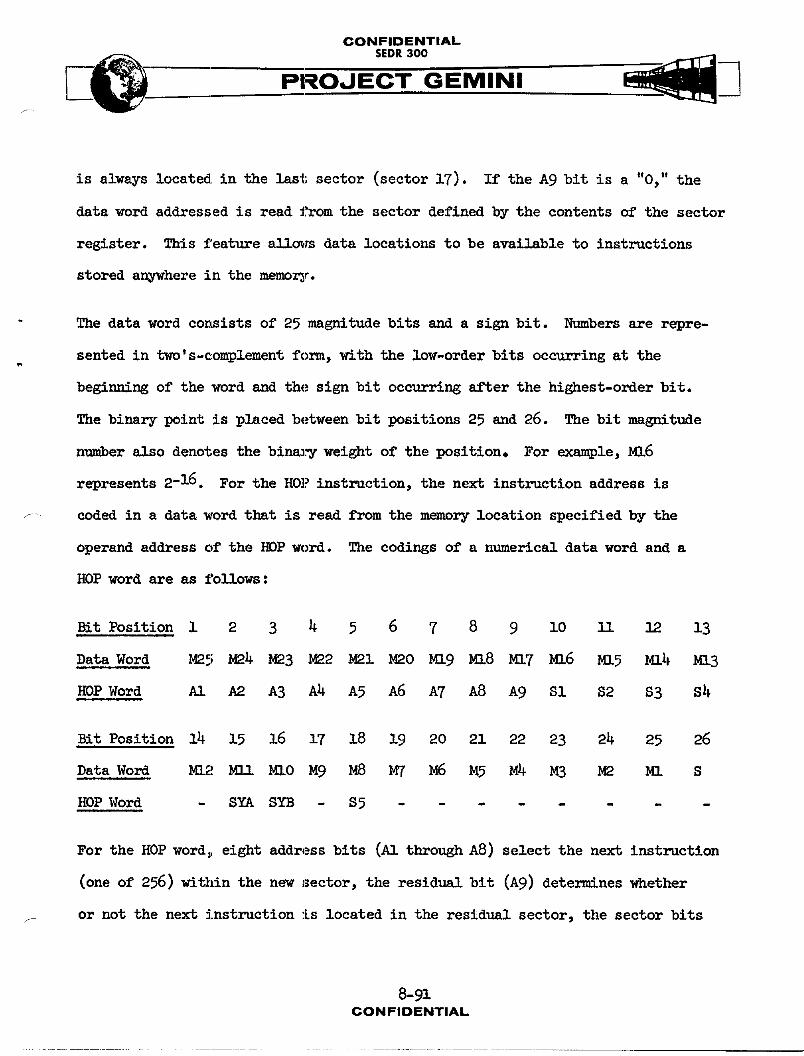
CONFIDENTIALSEDR300
PROJECTGEMINI
is always located in the last sector (sector 17). If the A9 bit is a "0," the
data word addressed is read from the sector defined by the contents of the sector
register. This feature allc_m data locations to be available to instructions
stored anywhere in the memory.
The data word consists of 25 magnitude bits and a sign bit. Numbers are repre-
sented in two's-complement form, with the low-order bits occurring at the
beginning of the word and the sign bit occurring after the highest-order bit.
The binary point is placed between bit positions 25 and 26. The bit _gn_tude
number _1_o denotes the bins_j weight of the position. For example, M16
represents 2-16 . For the HOP instruction, the next instruction address is
coded in a data word that is read from the memory location specified by the
operand address of the HOP word. The codings of a numerical data word and a
HOP word are as follows :
Bit Position i 2 S 4 5 6 7 8 9 i0 3_I 12 13
Data Word M25 M24 M23 M22 M21 M20 Ml9 MI8 M17 M16 M15 M14 M13
HOP Word AI A2 A3 A4 A5 A6 A7 A8 A9 S1 $2 $3 $4
BitPosition14 15 16 17 18 19 20 21 22 23 24 25 26
Data Word MI2 M11 MlO M9 M8 My M6 M5 M4 M3 M2 M1 S
HOP Word - SYA SYB - $5 ........
For the HOP word, eight address bits (AI through A8) select the next instruction
(one of 256) wit21in the new sector, the resid_,_! bit (A9) determines whether
or not the next instruction is located in the residual sector, the sector bits
8-91CONFIDENTIAL
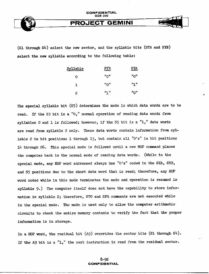
CONFIDENTIAL
SEDR300 ____PRO,J EC'" GEMINI
(SI through S_) select the new sector, and the syllable bits (SYA and SYB)
select the new syllable according to the following table:
S_llable SYB SYA
0 "0" 'tO"
1 "0" "l"
2 "l" "0"
The special syllable bit ($5) determines the mode in which data words are to be
read. If the $5 bit is a "0," normal operation of reading data words from
syllables 0 and 1 is followed; however, if the $5 bit is a "i," data words
are read from sy]]able 2 only. These data words contain information from syl-
lable 2 in bit positions 1 through 13, but contain all "O's" in bit positions
14 through 26. This special mode is followed until a new HOP command places
the computer back in the normal mode of reading data words. (While in the
special mode, any HOP word addressed always has "O's" coded in the SYA, SYB,
and S5 positions due to the short data word that is read; therefore, any HOP
word coded while in this mode terminates the mode and operation is resumed in
syllable 9. ) The computer itself does not have the capability to store infor-
mation in syllable 2; therefore, STO and SPQ commands are not executed while
in the special mode. The mode is used only to allow the computer arithmetic
circuits to check the entire memory contents to verify the fact that the proper
information is in storage.
In a HOP word, the residual bit (Ag) overrides the sector bits (SI through S_).
If the A9 bit is a "i," the next instruction is read from the residual sector.
8-92CONFIDENTIAL
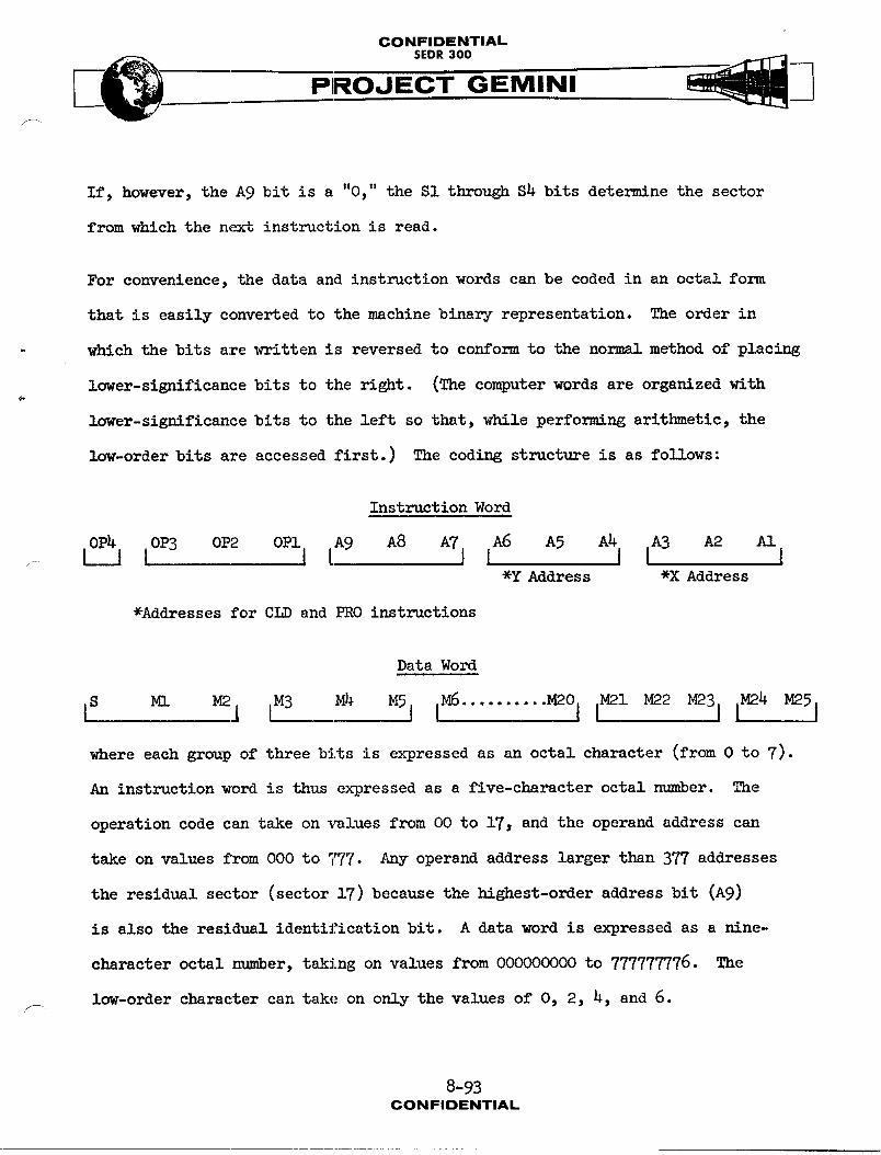
CONFIDENTIAL
SEOR300 .__.___ PROJECT GEMINI/
If, however, the A9 bit is a "0," the SI through $4 bits determine the sector
from which the next instruction is read.
For convenience, the data and instruction words can be coded in an octal form
that is easily converted to the machine binary representation. The order in
which the bits are written is reversed to conform to the normal method of placing
lower-significance bits to the right. (The computer words are organized with
iower-signlflcance bits to the left so that, while performing arithmetic, the
low-order bits are accessed first.) The coding structure is as follows:
Instruction Word
_ lOP3 OP2 OPlj [A9 A8 AT j IA6 A5 A4j IA3 A2 A1*Y Address *X Address
*Addresses for CLD and PRO instructions
Data Word
is m. _l [M3 M_ _51 IM6.......... _o I i_l _2 _31 1_4 _5 D
where each group of three bits is expressed as an octal character (from 0 to 7).
An instruction word is thus expressed as a five-character octal number. The
operation code can take on values from O0 to 17, and the operand address can
take on values from 000 to 777. Any operand address larger than 377 addresses
the residual sector (sector 17) because the highest-order address bit (A9)
is also the residual identification bit. A data word is expressed as a nine-
character octal m,_mber,taking on values from 000000000 to 777777776. The
low-order character can take on only the values of O, 2, 4, and 6.
8-93CONFIDENTIAL
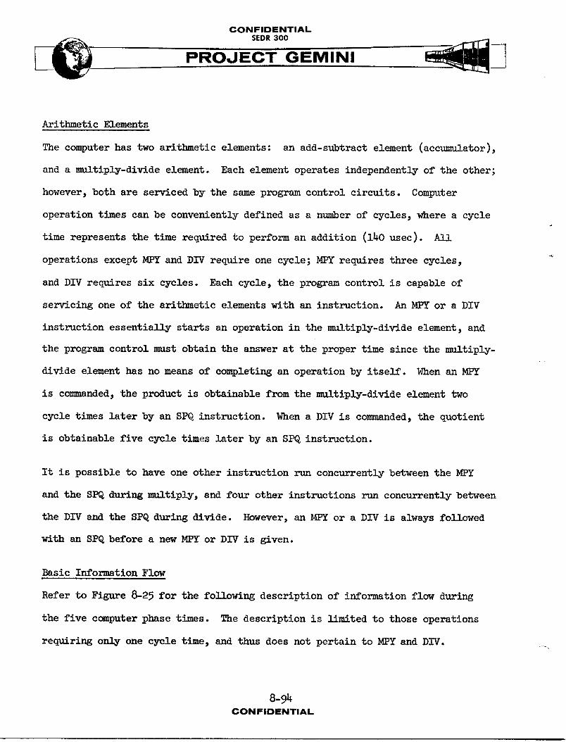
CONFIDENTIAL
PROJECT GEMINI
Arithmetic Elements
The computer has two arithmetic elements: an add-subtract element (accumulator),
and a multiply-dioxideelement. Each element operates independently of the other;
however, both are serviced by the same program control circuits. Computer
operation times can be conveniently defined as a number of cycles, where a cycle
time represents the time required to perform an addition (140 usee). AI]
operations except MPY and DIV require one cycle; MPY requires three cycles,
and DIV requires six cycles. Each cycle, the program control is capable of
servicing one of the arithmetic elements with an instruction. An MPY or a DIV
instruction essentially starts an operation in the multiply-divide element, and
the program control m_st obtain the answer at the proper time since the multiply-
divide element has no means of completing an operation by itself. _en an MPY
is co_,._nded,the product is obtainable from the multiply-dlvide element two
cycle times later by an SPQ instruction. When a DIV is comm_nded, the quotient
is obtainable five cycle times later by an SPQ instruction.
It is possible to have one other instruction run concurrently between the MPY
and the SPQ during multiply, end four other instructions run concurrently between
the DIV and the SPQ during divide. However, an MPY or a DIV is always followed
with an SPQ before a new MPY or DIV is given.
Basic Information Flew
Refer to Figure 8-25 for the fo_1owing description of information flew during
the five computer phase t_mes. The description is limited to those operations
requiring only one cycle time, and thus does not pertain to MPY and DIV.
8-94CONFIDENTIAL
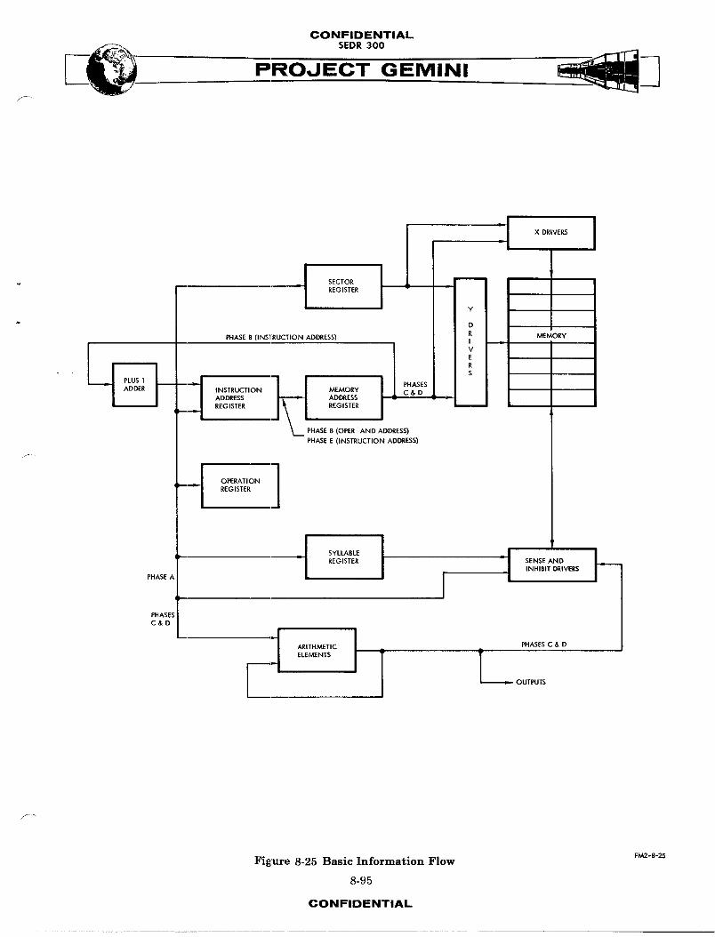
CONFIDENTIAL
SEOOoPROJECT GEMINI
;I XORIVERSREGISTER v
Y !
R MEMORYPHASE B (INSTRUCTION ADDRESS) I
J\t I : v
I! ' E1 R
1_ PHASES L SINSTRUCTION MEMORY C & DADDRESS ADDRESS . :REGISTER REGISTER
PHASE R (OPER AND ADDRESS)PHASE E (INSTRUCTION ADDRESS)
1REGISTER
I I IL REGISTER L SENSE ANDINHIBIT DRIVERS
PHASE.6 J
PHASE._C&D
l • OUTPUTS
Figure 8-25 Basic Information Flow FM2-8-25
8-95
CONFIDENTIAL
CONFIDENTIAL
PROJECT GEMINI
During phase A, the 13-bit instruction word is read from memory and stored in
the instruction address register. The address of the instruction is defined
by the contents of the memory address register, the sector register, and the
sy_able register. The four operation code bits (OP1 through 0P4) are stored
in the operation register. During phase B, the operand address bits (A1 through
A8) are serially transferred from the instruction address register to the memory
address register. Simultaneously, the instruction address stored in the memory
address register is incremented by plus one and stored in the instruction
address register. The operation specified by the operation code bits is per-
formed during phases C and D. Durlngphase E, the next instruction address,
stored in the instruction address registe_ is transferred to the memory address
register.
Four of the one-cycle operations do not strictly adhere to the above information
flow. These operations are HOP, TRA, TMI, and TNZ. For the HOP instruction,
data read from memory during phases C and D is transferred directly to the
instruction address register, the sector register, and the syllable register.
For the TRA, TMI, and TNZ operations, the transfer of the next instruction address
from the instruction address register during phase E is inhibited to allow the
operand address to become the next instruction address.
Instruction Information Flow
Flow Diagram: The instruction information flow diagram (Figure 8-26) should
be used along with the following descriptions.
CONFIDENTIAL
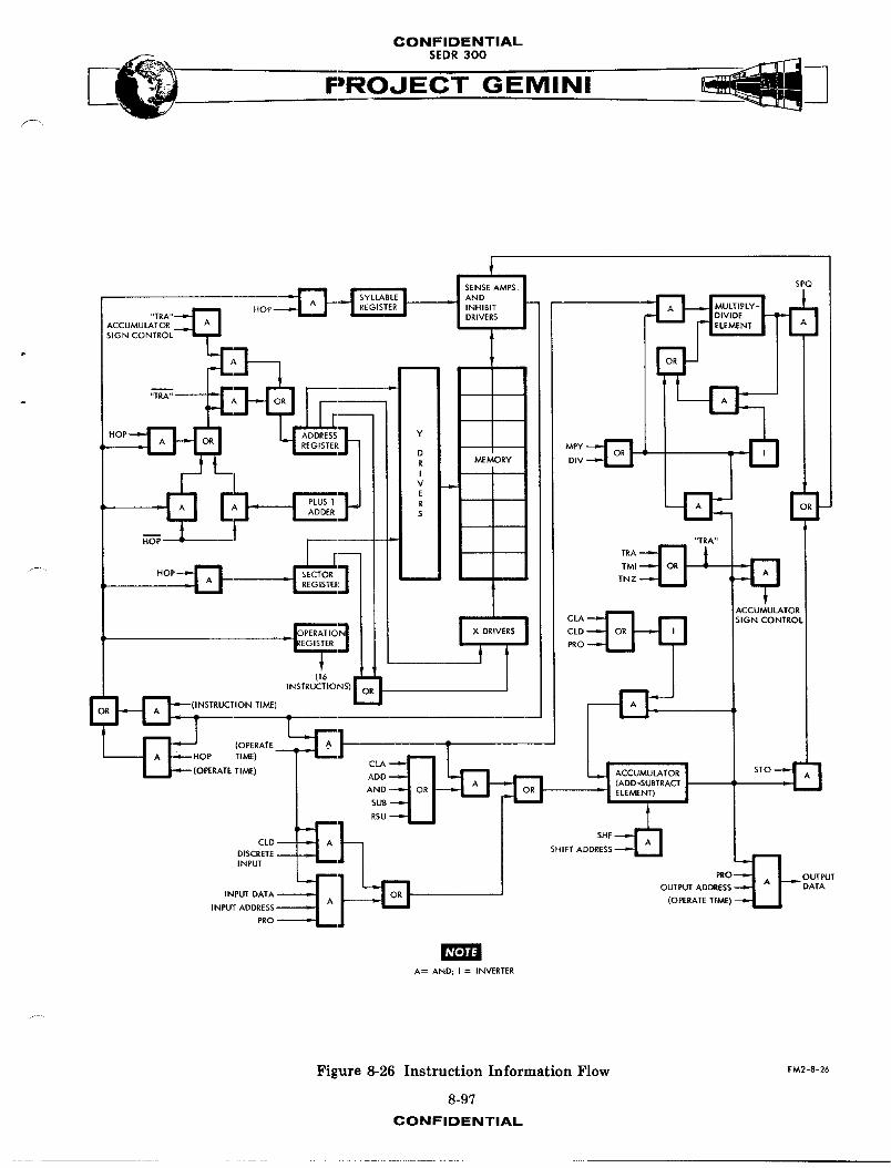
CONFIDENTIAL
PROJECT GEMINI
"IRA*' -- --
HOP
PLUS 1 i - R'I
TMI :_
"/- " HOP _ _ TNZ
-I RjREGISTE
ACCUMULATORCLA "--'_ I Ipm_l SIGN CONTROL
PERATIO _ CLDU6 |
[ =I.,_"_(INSTRUCTION TIME) INSTRUCTIO_IS)J
RATE ADD STO
RSU
CLD-- _DISCRETE SHIFT ADDRESS •INPUT
_ OUTPUTOUTPUT AD DATA
INPUT DATA - (OPERATE TIME)INPUT ADDRESS
PRO
NOTE
A= AND; I = INVERTER
Figure 8-26 Instruction Information Flow FM2-8-26
8-97
CONFIDENTIAL
CONFIDENTIAL
PROJECT GEMINI
CLA Operation
During phases C and D, the data that was contained in the accumulator during
phases A and B is destroyed. Simultaneously, new data from the selected memory
location is transferred through the sense amplifiers and into the accumulator.
Durlng phases E R-d A, the new data is recirculated so as to be available in
the accumulator during phases A and B.
ADD Operation
During phases C and D, new data from the selected memory location is transferred
through the sense amplifiers and into the accumulator. Here, the new data is
added to the data that was contained in the accumulator during phases A and B.
During phases E and A, the s_m data is recirculated so as to be available in
the acc_m_lator during phases A and B.
SUB Operation
During phases C and D, new data from the selected memory location is transferred
through the sense amplifiers and into the accumulator. Here, the new data is
subtracted from the data that was contained in the accumulator during phases
A and B. During phases E and A, the difference data is reeirculated so as to
be available in the accumulator during phases A and B.
RSU Operation
During phases C and D, new data from the selected memory location is trans-
ferred through the sense amplifiers and into the accumulator. Here, the data
that was contained in the accumulator during phases A and B is subtracted from
the new data. During phases E and A, the difference data is recirculated so as _-
to be available in the accumulator during phases A and B.
8-98CONFIDENTIAL
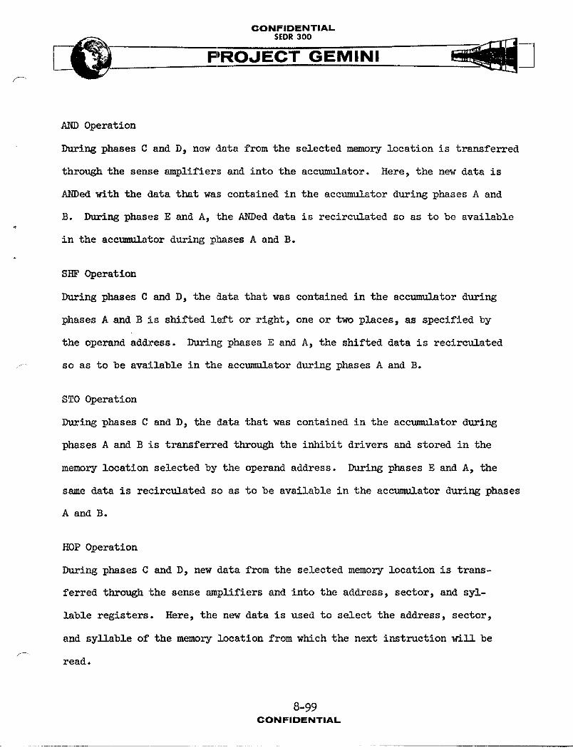
CONFIDENTIALSEDR 300
AND Operation
During phases C and D, new data from the selected memory location is transferred
through the sense amplifiers and into the accumulator. Here, the new data is
ANDed with the data that was contained in the accumulator during phases A and
B. During phases E and A, the ANDed data is recirculated so as to be available
in the acctma_lator during plhases A and B.
SHF Operation
During phases C and D, the data that was contained in the accu_1_tor during
phases A and B is shifted left or right, one or two places, as specified by
the operand address. During phases E and A, the shifted data is recirculated
_ so as to be available in the accumulator during phases A and B.
STO Operation
During phases C and D, the data that was contained in the accumulator during
phases A and B is transferred through the inhibit drivers and stored in the
memory location selected by the operand address. During phases E and A, the
same data is recirculated so as to be available in the accumulator during phases
A and B.
HOP Operation
During phases C and D, new data from the selected memory location is trans-
ferred through the sense amplifiers and into the address, sector, and syl-
lable registers. Here, the new data is used to select the address, sector,
and syllable of the memory location from which the next instruction willbef-
read.
8-99CONFIDENTIAL
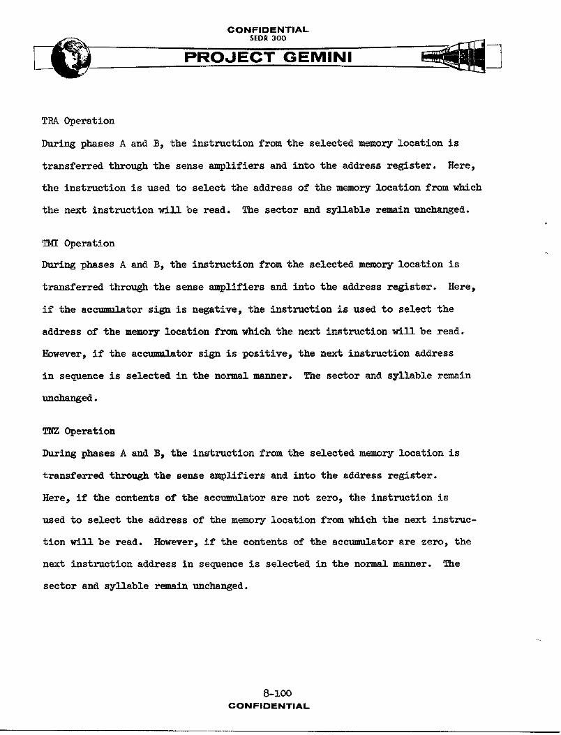
CONFIDENTIAL
PROJECT GEMINI
TRA Operation
During phases A and B, the instruction from the selected memory location is
transferred through the sense amplifiers and into the address register. Here,
the instruction is used to select the address of the memory location from which
the next instruction will be read. The sector and syllable remain unchanged.
_I Operation
Durlng phases A and B, the instruction from the selected memory location is
transferred through the sense amplifiers and into the address register. Here,
if the acc_,_,lAtorsign is negative, the instruction is used to select the
address of the m_mnry location from which the next instruction will be read.
However, if the ac_--nl-tor sign is positive, the next instruction address
in sequence is selected in the normal manner. The sector and syllable remain
unchanged.
TNZ operation
During phases A and B, the instruction from the selected memory location is
transferred through the sense amplifiers and into the address register.
Here, if the contents of the accumulator are not zero, the instruction is
used to select the address of the memory location from which the next instruc-
tion w_1_ be read. However, if the contents of the accumulator are zero, the
next instruction address in sequence is selected in the normal m_nner. The
sector and syllable r_mAin unchanged.
8-100CON FIDENTIAL
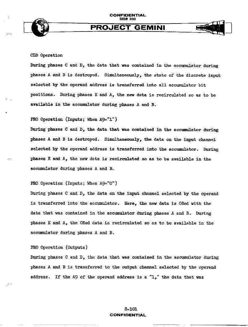
CONFIDENTIAL
SEDR 300
PROJECT GEMINI
CLD Operation
During phases C and D, the data that was contained in the accumulator during
phases A and B is destroyed. Simultaneously, the state of the discrete input
selected by the operand address is transferred into all accumulator bit
positions. During phases E and A, the new data is recirculated so as to be
available in the accumulator during phases A and B.
PRO Operation (Inputs; _hen Ag="I")
_i_g phases C and D, the data that was contained in the ac_tor d_ring
phases A and B is destroyed. S_,ItaneQ-osly, the data on the input channel
selected by the operand address is transferred into the ac_ator. During
f phases E A_n_dA, the new data is recirculated so as to be available in the
accumulator during phases A and B.
PRO Operation (Inputs; When A9="0")
During phases C and D, the data on the input chin-el selected by the operand
is transferred into the accumulator. Here, the new data is ORed with the
data that was contained in the accumulator during phases A and B. During
phases E and A, the ORed data is recirculated so as to be available in the
accomulator during phases A and B.
PRO Operation (Outputs)
During phases C and D, the data that was contained in the accumulator during
phases A and B is transferred to the output ch_-nel selected by the operand
address. If the A9 of the operand address is a "i," the data that was
8-101
CONFIDENTIAL
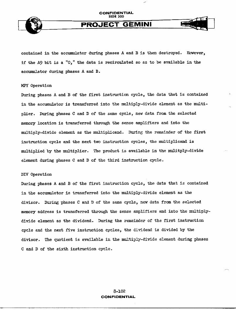
CONFIDENTIALSEDR 300
P RO J EC"T- GEMINI
contained in the accumulator during phases A and B is then destroyed. However,
if the A9 bit is a "0," the data is recir__1_ted so as to be available in the
acc11_IAtor during phases A and B.
MPY Operation
During phases A and B of the first instruction cycle, the data that is contained
in the accumulator is transferred into the multiply-divide element as the multi-
plier. During phases C and D of the same cycle, new data from the selected
memory location is transferred through the sense amplifiers and into the
multiply-divide element as the multiplicand. During the remainder of the first
instruction cycle and the next two instruction cycles, the multiplicand is
m_ltiplied by the multiplier. The product is available in the _11!tply-divide
element during phases C and D of the third instruction cycle.
DIV Operation
During phases A and B of the first instruction cycle, the data that is contained
in the accumulator is transferred into the multiply-divide element as the
divisor. During phases C and D of the same cycle, new data from the selected
memory address is transferred through the sense amplifiers and into the multiply-
divide element as the dividend. During the remainder of the first instruction
cycle and the next five instruction cycles, the dividend is divided by the
divisor. The quotient is available in the multiply-divide element during phases
C and D of the sixth instruction cycle.
8-102CONFIDENTIAL

CONFIDENTIAL
,,:_ SEDR300
SPQ Operation
During phases C and D, the product or quotient that is contained in the multiply-
divide element is transferred through the inhibit drivers and stored in the
memory location selected by the operand address.
NOTE
In the subsequent program and interface
descriptions, the signals that are pro-
gra_mmd by CLD and PRO instructions are
sometimes referred to as DI (discrete
input) or DO (discrete output) signals.
The t_o digits following the DI or DO/
are the Y and X addresses, respectively,
of the instruction.
Operational Pro6ram
The operational program consists of six basic routines : Executor, Pre-Launch,
Ascent, Catch-Up, Rendezvou_ and Re-Entry (Catch-Up & Rendezvous not applicable
for S/C 3, 4 & 7). Each routine is made up of several subroutines. Some of
the subroutines are common to all routines while some are unique to a particular
routine. Each subroutine consists of a series of program instructions which,
when executed, cause specific computer circuits to operate. The initiation of
a particular routine is controlled by the Computer Mode switch on the Pilots'
Control and Display Panel. Once a routine is initiated, the subroutines within
the routine are executed automatically.
8-103CONFIDENTIAL

CONFIDENTIAL
SEDR300 _3PROJECT GEMINI
Executor Routine
The Executor routine selects and handles the functions common to all other routines.
The program flow for this routine is shown on Figure 8-27. The individual
blocks shown on the figure are explained as follows :
(a) Block 1. When the computer is turned on, the first memory loca-
tion addressed is address 000, sector 00, syllable O. This
memory location is the first memory address utilized by the
Executor routine.
(b) Block 2. The operational program utilizes special predetermined
memory locations which are designed as logical choice (LC)
addresses. At certain times, the sign bits at these LC addresses
are set minus ("l") or plus ("0"). The sign bits of specific
LC addresses are then checked during the execution of the
routines and, depending on whether they are plus or minus,
special series of program instructions are executed.
(c) Block 3- The following discrete outputs are set plus: start
computation, computer running, second stage engine cutoff,
atuopilot scale factor, AGE data clock, and time reference
system gate.
(d) Block 4. The processor real time count is read for utilization
by the individual routines.
(e) Block 5. The accelerometer subroutine is executed to verify
that the X, Y, and Z velocity signals from the accelerometers
equal zero.8-1o4
CONFIDENTIAL
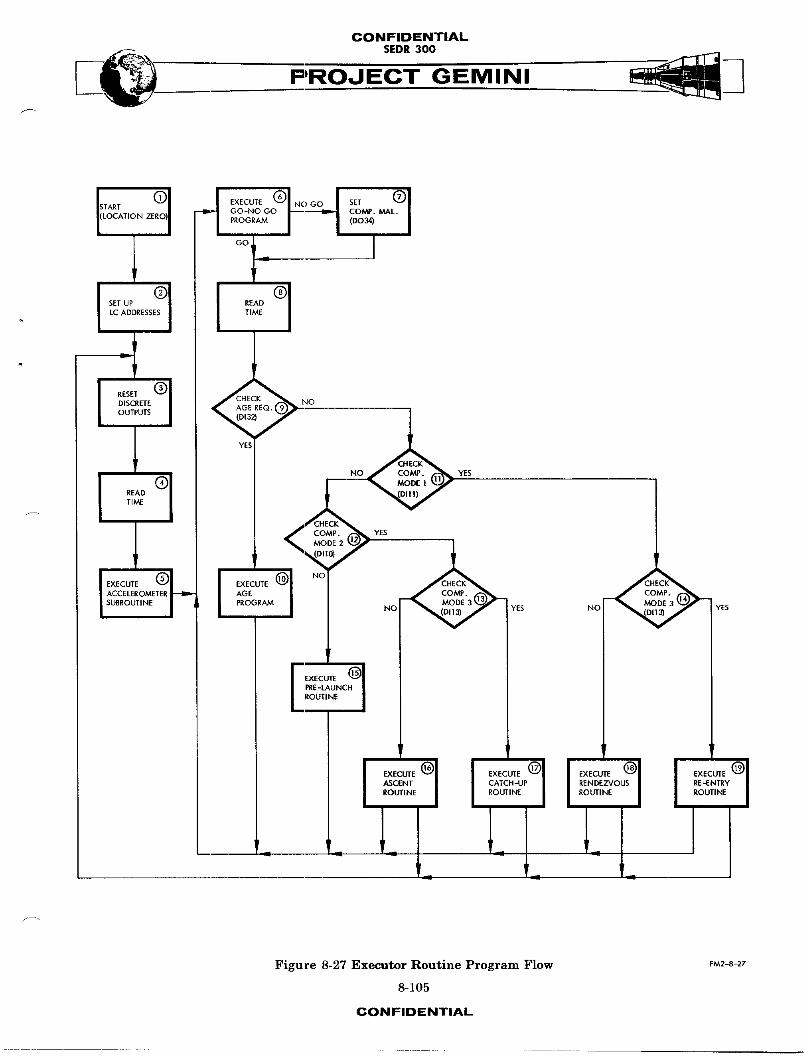
CONFIDENTIALSEDR 300
°°_ I
l YES1 NO YES
1 ,
NO_ jYES
_f
I l I I
Figure 8-27 Executor Routine Program Flow FM2-8-27
8-105
CONFIDENTIAL

CONFIDENTIAL
SEDR300 _ .._._PROJ'E-C"T GEMINI
(f) Block 6. A special go, no-go diagnostic program is executed to
determine if the basic computer arithmetic circuits are function-
ing properly. If these circuits fail, the NO GO path is followed;
if there is no failure, the GO path is followed.
(g) Block 7. Program instruction PRO34 is executed. The execution
of this instruction causes the computer malfunction circuit to
be conditioned.
(h) Block 8. The processor real time count is read and updated
for utilization by the individual routines.
(i) Block 9. Program instruction CLD32 is executed to determine the .....
condition of the AGE request discrete input. If the input is
a "l," the YES path is followed; if the input is a "0," the NO
path is followed.
(j) Block lO. Special check-out tests are executed by the AGE.
Both the Gemini Launch Vehicle and the computer can be checked
out.
(k) Blocks ll through 14. Program instructions CLDIO, CLDll, and
CLDI3 determine the condition of the discrete inputs from the
Computer Mode switch. This switch is manually controlled by the
pilot and, depending upon which mode is selected, causes a
partic111_r routine to be executed until the switch setting isJ-_
changed or until the computer is turned off. The combinations
8-106CONFIDENTIAL
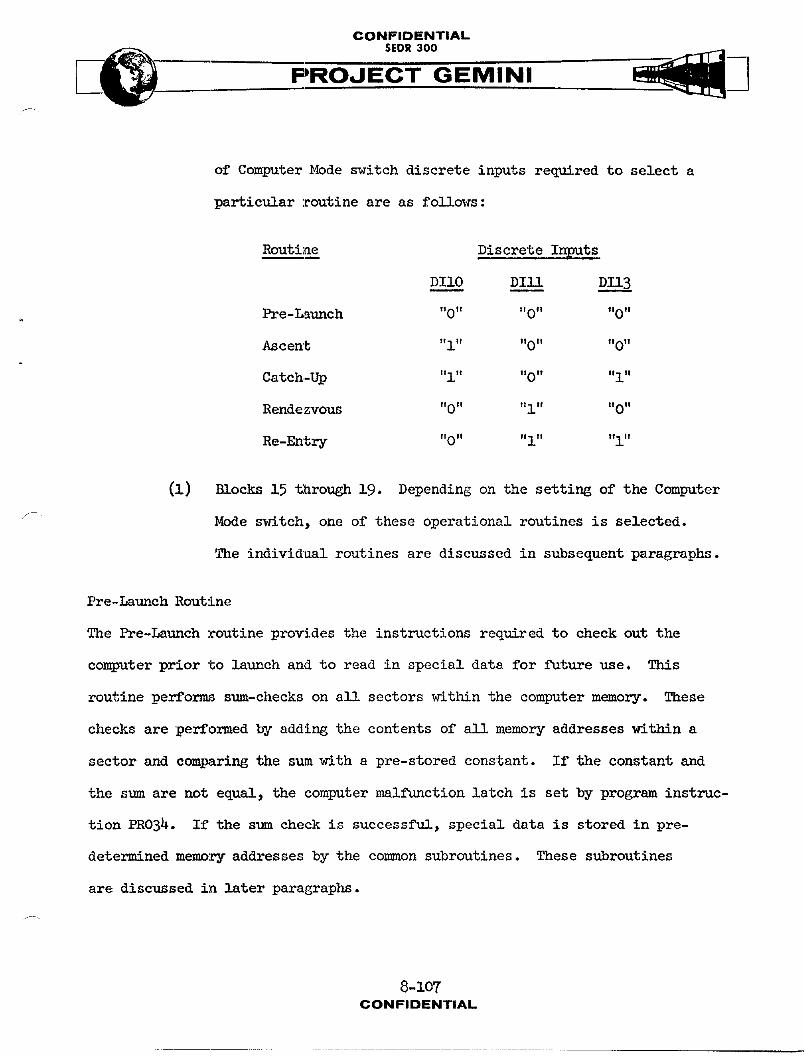
CONFIDENTIAL
__ SEDR300
PROJECi" GEMINI
of Computer Mode switch discrete inputs required to select a
particular :routine are as follies :
Routine Discrete In_mlts
DI10 Dill DII3
Pre-Launch "0" "0" "0"
Ascent "l" "0" "0"
Catch-Up "l" "O" "i"
Rendezvous "0" "l" "O"
Re-Entry "0" "i" "I"
(i) Blocks 15 through 19. Depending on the setting of the Computer
F Mode switch, one of these operational routines is selected.
The indivi@aal routines are discussed in subsequent paragraphs.
Pre-Launch Routine
The Pre-Launch routine provides the instructions required to check out the
computer prior to launch and to read in special data for future use. This
routine performs sum-checks on all sectors within the computer memory. These
checks are performed by adding the contents of a]l memory addresses within a
sector and comparing the sum with a pre-stored constant. If the constant and
the sum are not equal, the computer malfunction latch is set by program instruc-
tion PRO34. If the sum check is successful, special data is stored in pre-
determined memory addresses by the common subroutines. These subroutines
are discussed in later paragraphs.
8-IO7
CONFIDENTIAL
CONFIDENTIALSEDR 300
Ascent Routine
The Ascent routine provides the computations required for back-up ascent
guidance. After the computer has been placed in the Ascent mode, special
data is transferred to the computer via the Digital Command System. This data
is then continually updated and used to keep track of the orbit plane and the
platform attitudewith respect to Earth. Thirty seconds after the special data
is first transferred to the computer, the Inertial Guidance System is placed
in the Inertial mode. The computer continually monitors and stores the plat-
form gimbal angle values during this time. After lift off, the computer per-
forms a back-up guidance function. If necessary, however, the computer can be
used to perform primaryguidance during Ascent.
Catch-UpRoutine
The Catch-Up routine is not utilized in S/C 3, 4 or 7, because they are of
non-rendezvous configuration. For information pertaining to this routine, refer
to Vol. II of this document.
Rendezvous Routine
The Rendezvous routine is not utilized in S/C 3, 4 or 7, because they are of
non-rendezvous configuration. For information pertaining to this routine,
refer to Vol. II of this document.
Re-Entry Routine
The Re-Entry routine provides the computations required for re-entry guidance.
During the Re-Entry mode, the retro velocity is monitored and retro velocity
8-108CONFIDENTIAL

CONFIDENTIAL
__ SEDR300
PROJEC'i" GEMINIf
errors are calculated. The distance and heading of the spacecraft with respect
to the desired landing site are calculated, and the down range travel to
touchdown is predicted. T_ routine also provides signals to COmmRnd the space-
craft roll msneuvers during:re entry andprovides a display of attitude errors
as detailed on pages 8-1B7 and 8-138.
NOTE
The following subroutines are common to
the previously described routines: G4mhal
Angle, Accelerometer, Digital C_-.,_d Sys-
tem, Instrumentation System, and Maim1
Data. Therefore, a description of each of
these subroutines follows.
GimbalAngle Subroutine
The Gimbal Angle subroutine reads and processes the gimbal angles for the
pitch, yaw, and roll axes of the Inertial Platform. During a computer word
time, the gimbal angle processor reads in one gimbal angle value and tr_nafers
a previously read gimbal angle value to the accumulator. Thls method enables
a faster processing operation than if the angle for each axis were processed
individually. Approximate1_ 5 ms elapses between the processing of one g_mbal
angle value and the processing of the next g_mbal angle value. (The gimbal
angle value is the binary equivalent of the act1_nl gimbal angle.)
8-109CONFIDENTIAL
CONFIDENTIAL.
$EDR300 .__]PROJECT GEMINI i
Accelerometer Subroutine
The Accelerometer subroutine processes velocity signal inputs from the Inertial
Measuring Unit. These signals, which represent velocity for the X, Y, and Z
axes of the spacecraft, are generated by accelerometers. Due to the construction
and adjustment of the accelerometers, the signals contain inherent bias and
alignment errors. The subroutine corrects these errors and stores the corrected
velocity values in predetermined computer memory locations. The computer input
processor reads the X, Y, and Z velocity signals, and transfers them to the
processor delay line. The delay line is then read by the subroutine at periodic
intervals which depend on the selected mode or routine.
DigitalComm_udSystemSubroutine
The Digital Commsnd System subroutine reads and processes data furnishedby
the Digital CommAnd System (DCS). The DCS furnishes the computer with special
24-bit words consisting of 6 address bits and 18 data bits. The address bits
indicate where the data bits are to be stored in the computer memory. The sub-
routine first determines if data is available from the DCS. If data is avail-
able, the subroutine then reads the data into the accumulator. Next, the address
and data bits are separated. The data bits are then stored in the computer
memory address specified by the address bits. After this data is stored, it
is used as constants by other subroutines. The DCS subroutine also contains
instructions which provlde extended DCS addresses. (Address lO0-117). The
recognition of addresses 20 and 21 excersises the proper operational program
loops to store the data in the computer. For each DCS extended address insert, it
is necessary tomake two transmissions and this must be accomplished in the ....
8-110CONFIDENTIAL
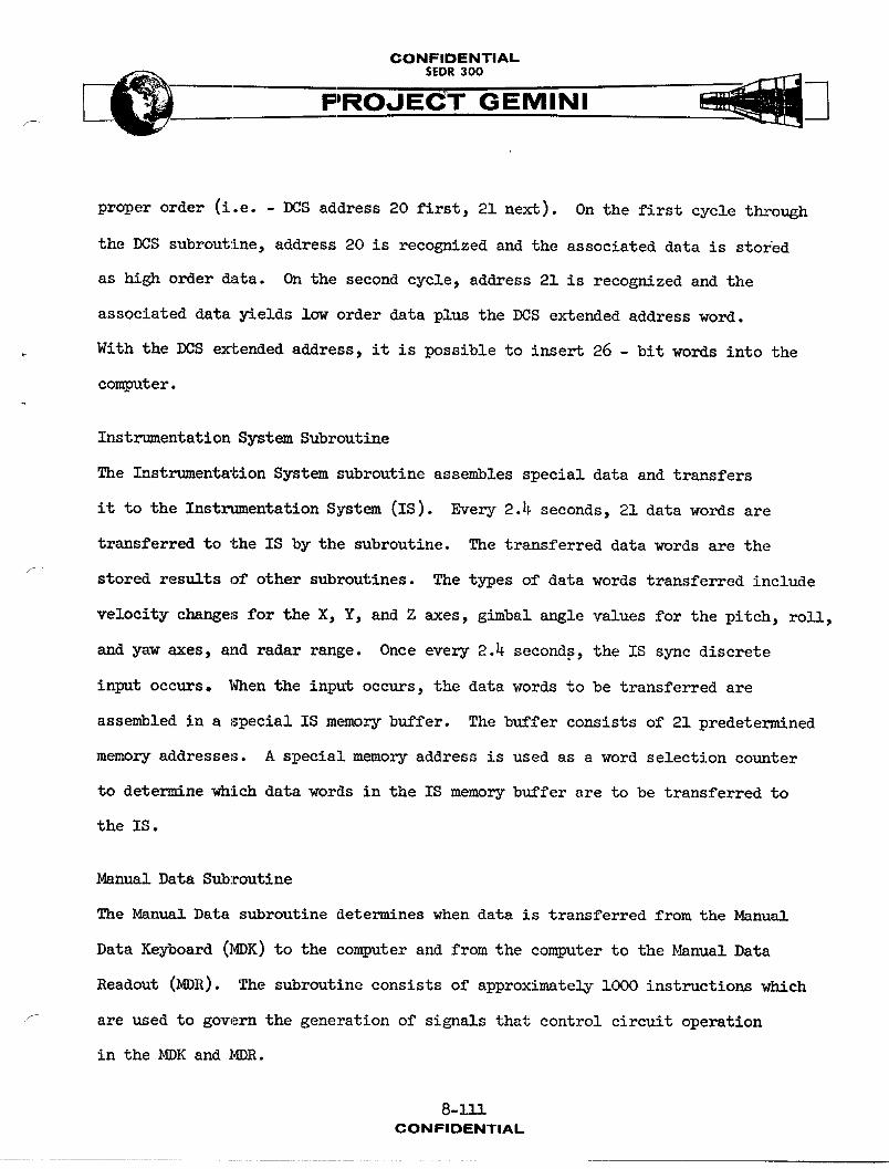
CONFIDENTIAL
PROJECT GEMINI
proper order (i.e. - DCS address 20 first, 21 next). On the first cycle through
the DCS subroutine, address 20 is recognized and the associated data is stored
as high order data. On the second cycle, address 21 is recognized and the
associated data yields low order data plus the DCS extended address word.
With the DCS extended address, it is possible to insert 26 - bit words into the
computer.
Instrumentation System Subroutine
The Instrumentation System subroutine assembles special data and transfers
it to the Instrumentation System (IS). Every 2.4 seconds, 21 data words are
transferred to the IS by the subroutine. The transferred data words are the
stored results of other subroutines. The types of data words transferred include
velocity changes for the X, Y, and Z axes, gimbal angle values for the pitch, roll,
and yaw axes, and radar range. Once every 2.4 seconds, the IS sync discrete
input occurs. When the input occurs, the data words to be transferred are
assembled in a special IS memory buffer. The buffer consists of 21 predetermined
memory addresses. A special memory address is used as a word selection counter
to determine which data words in the IS memory buffer are to be transferred to
the IS.
Manual Data Subroutine
The Manual Data subroutine determines when data is transferred from the Manual
Data Keyboard (MDK) to the computer and from the computer to the _nual Data
Readout (MDR). The subroutine consists of approximately lOOO instructions which
are used to govern the generation of signals that control circuit operation
in the MDK and MDR.
8-111CONFIDENTIAL
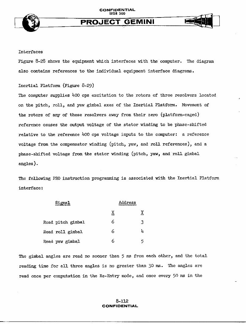
CONFIDENTIAL
SEDR300 _._PROJECT GEMINI
Interfaces
Figure 8-28 shows the equipment which interfaces with the computer. The diagram
also contains references to the individual equipment interface diagrams.
Inertial Platform (Figure 8-29)
The computer s_pplies 400 cps excitation to the rotors of three resolvers located
on the pitch, roll, and yaw g_mbal axes of the Inertial Platform. Movement of
the rotors of any of these resolvers away from their zero (platform-caged)
reference causes the output voltage of the stator winding to be phase-shifted
relative to the reference 400 cps voltage inputs to the computer: a reference
voltage from the compensator _lnding (pitch, yaw, and roll references), and a
phase-shifted voltage from the stator winding (pitch, yaw, and roll gimbal
angles).
The following PRO instruction programm_ ng is associated with the Inertial Platform
interface:
Si$nsl Address
X Y
Readpitchgimbal 6 3
Readroll] gimbal 6 4
Readyawgimbal 6 5
The gimbal angles are read no sooner than 5 ms from each other, and the total
reading time for all three angles is no greater than 30 ms. The angles are
read once per computation in the Re-Entry mode, and once eve1_j50 ms in the
8-112CONFIDENTIAL
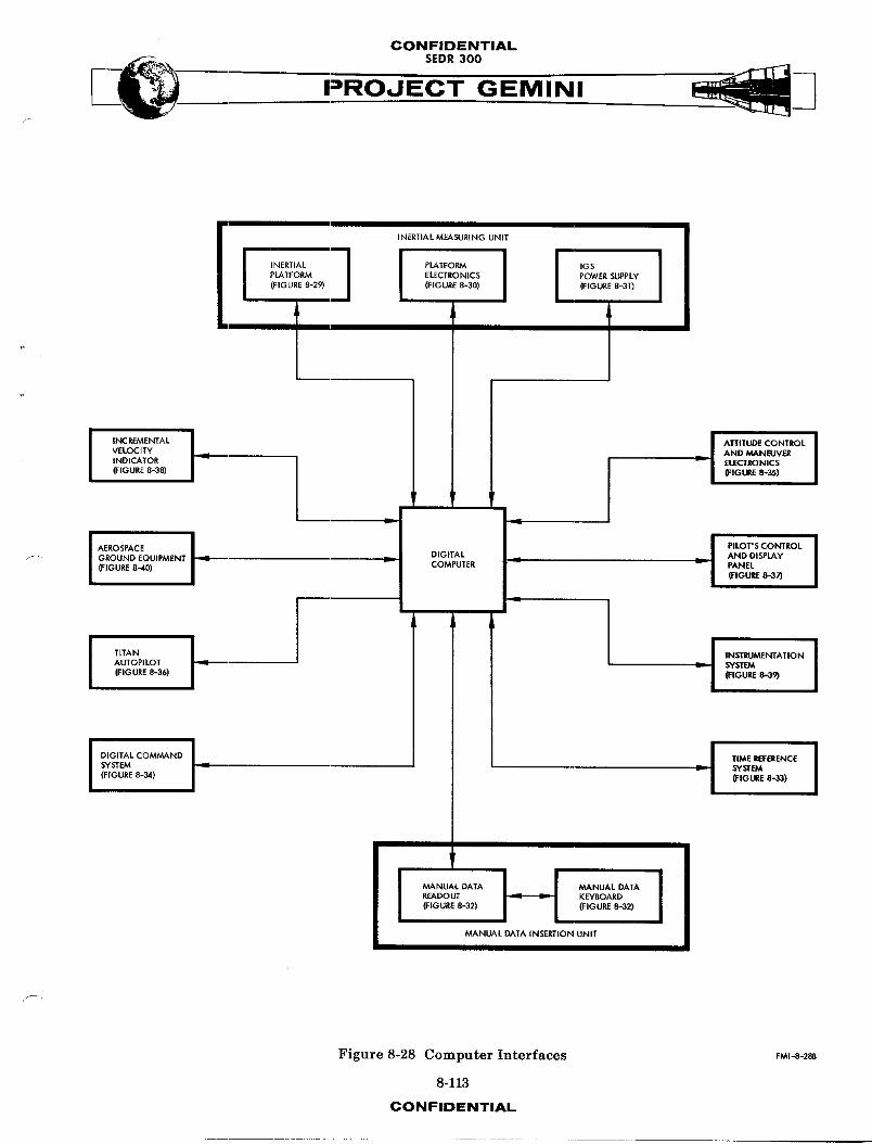
CONFIDENTIAL
PROJECT GEMINI/
INERTIAL MEASURING UNIT
PLATFORM ELECTRONICS POWER SUPPLY(FIGURE 8-29) (FIGURE 8-30) (FIGURE 8-31)
1' °E ALI I °LIVELOCITY AND MANEUVERINDICATOR _ I "_ E_RONIC$
(FIGURE 8-,38) I (FIGURE 8-35)
r
f GROUND EQUIPMENT _ _ DIGITAL AND DISPLAy(FIGURE 8-40) COMPUTER _'_ _--- PANEL
(FIGURE 8-37)
AUTOPILOT _. ._ SYST_V.
(FIGURE 8-36) 0:IGURE 8-39)
IO'O'TALCOM "O I(FIGURE8--34) {FIGURE8-33)
r
MANUAL DATA H MANUAL DATA I
READOUT KEYBOARD(FIGURE 8-32) (FIGURE 8-32)
MANUAL DATA INSERTION UNIT
Figure 8-28 Computer Interfaces FMI-8-2_.
8-113
CONFIDENTIAL
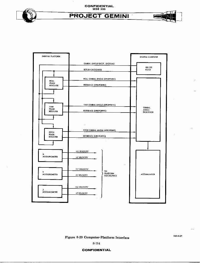
CONFIDENTIAL
PROJECT GEMINI
INERTIALPLATFORM DIGITALCOMPUTER
RETURN (XCEGAEG) FILTER
ROLL GIMBAL ANGLE (XPR4PPSRRC) i iREFERENCE (XPR4PCRF£C)
- GIMBAL
REFERENCE (Xi_3PCRPYC) ANGLEPROCESSOR
REFERENCE (XPR1PCRPPCJ
' 1ACCELEROMETER -X VE LOCI'IY
Y PLATFORM ACCUMULATORACCELEROMETER -Y VELOCITY • ELECTRONICS
Z c
ACCE LEROMETER -Z VELOCITY L
FM2-8-29Figure 8-29 Computer-Platform Interface
8-114
CONFIDENTIAL

CONFIDENTIAL
SEDR300
PROJ EC-T" GEMINI
Ascent mode. These angles are gated, as true magnitude, into the accumulator
S, and i through 14 bit positions with the 15 through 25 bit positions being
zero. The accumulator value from the first PRO instruction is discarded. Each
of the next three PRO instructions results in an accumulator value of the
gimbal angle read by the previous PRO instruction, as follows:
(a) PROS6 (read pitch; process previously read angle)
(b) Discard previously read angle
(c) Wait5ms
(d) PRO46 (read ro11; process pitch)
(e) STO pitch
(f) Wait 5 msf -
(g) PRO56 (read yaw; process roll)
(h) s_ roll
(i) Wait 5 ms
(j) PROS6 (read pitch; process yaw)
(k) sToyaw
The computer inputs from the Inertl al Platform are summarized as follows:
(a) Roll gimbsd angle (XPR4PPSRRC) and reference (XPR4PCRPRC)
(b) Yaw g_mbal angle (XPRBPPSRYC) and reference (XPRBPCRPYC)
(c) Pitch g_mbsl angle (XPRIPPSRPC) and reference (XPRII_RPPC)
The computer output to the Inertial Platform is sllmmarizedas fo1_lows:
Gimbal angle excitation (XCEGAE) and return (XCEGAEG)
8-1.!5CONFIDENTIAL
CONFIDENTIAL
PROJECT GEMINI
Platform Electronics (Figure 8-30)
Outputs derived from each of the three platform accelerometers are sul_plied to
the cc_puter as incremental velocity pulses (+X and -X delta velocity, +Y
and -Y delta velocity, and +Z and -Z delta velocity). An up level on one line
denotes a positive increment of velocity while an up level on the other line
denotes a negative increment of velocity.
The following PRO instruction programming is associated with the Platform
Electronics interface :
Signal Address Processor
X Y PhaseTime
Read X delta velocity 5 4 2
ReadY deltavelocity 5 4 3
ReadZ deltavelocity 5 4 4
The input processor accumulates the incremental velocity pulses on the processor
delay line in two's-complement form. The velocity pulses have a maxinmm fre-
quency of 3.6 kc per channel with a minimum separation of 135 usec between any
plus and minus pulse for a given axis. Three input circuits are used to buffer
the plus and minus pulses, one circuit for each axis. The buffered velocity
pulse inputs are sampled during successive processor phases and read into a
control circuit. This control circuit synchronizes the inputs with the processor
timing and establishes an add, subtract, or zero control for the processor carry-
borrow circuit. The accumulated velocity quantities are read into the accumulator
8-ll6CONFIDENTIAL
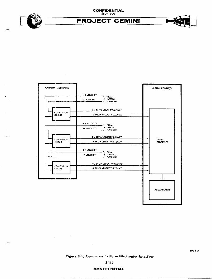
CONFIDENTIAL
PROJECT GEMINI
PLATFORM ELECTRONICS DIGITAL COMPUTER
+ X VELOCITY
FROM
I -X VELOCITY INERTIAL
PLATFORM
+X DELTA VELOCITY (XEDVPL)CONVERSIONCIRCUIT -X DELTA VELOCITY (XEDVML)
+ Y VELOCITY
FROMPLATFORM
_" " + Y DELTA VELOCITY (XEDVP0CONVERSION INPUT
CIRCUIT -Y DELTA VELOCITY (XEDVMY) PROCESSOR
+Z VELOCITY FROM
PLATFORM
÷ Z DELTA VELOCITY (XEDVPZ) L
SION -Z DELTA VELOCITY (XEDVMZ) L
ACCUMULATOR
FM2-8_30
Figure _.30 Computer-Platform Electronics Interface
8-117
CONFIDENTIAL
CONFIDENTIAL
SEDR300 ______PROJ GEMINI
S, and i through 12 bit positions in two's-complement form via a single PRO45
instruction, as follows :
(a) Processor phase 2 - read accumulated X velocity
(b) Processor phase 3 - read accumulated Y velocity
(c) Processor phase 4 - read accumulated Z velocity
As the accelerometer values are read into the accumulator, the delay line is
automatically zeroed so that each reading represents the change in velocity from
the previous reading.
The computer inputs from the Platform Electronics are summarized as follows :
(a) +Xdeltavelocity(XEDVPL)
(b) -X delta velocity (XEDVML)
(c) +Y delta velocity (XEDVPY)
(d) -Y delta velocity (XEDVMY)
(e) +Z delta velocity (XEDVPZ)
(f) -Z delta velocity (XEDVMZ)
IGS Power Supply (Figure 8-31): The computer supplies a filtered 28 VDC sig_!
to the IGS Power Supply to control the DC power supplied to the computer. The
IGS Power Supply supplies power to the computer within O.3 second after receiving
the 28 VDC power control signal. When the computer power control signal drops
to 2 VDC, the IGS Power Supply removes DC power from the computer within 0.3
second. The 26 VAC, 400 cps power furnished to the computer by the IGS Power
Supply is not controlled by the computer power control signal, and is therefore -.
present at the computer whenever the IGS Power Supply is operating.
8-n8CONFIDENTIAL
CONFIDENTIAL
PROJECT GEMINIf
The computer inputs from the IGS Power Supply are s-mm_rized as follows :
(a) +27.2 VDC (XSF27VDC) and return (XSP27VDCRT)
(b) -27.2 VDC qIXSM27VDC)and return (XSM27VDCRT)
(c) -20 VDC (XSF2OVDC) and return (XSI_2DVDCRT)
(d) +9.3 VDC (XSP9VDC) and return (XSP9VDCRT)
(e) 26 VAC (X_6VAC) and return (XS26VACRT)
(f) +28 VDC filtered (XSP28VDC) and return (XSF28VDCRT)
The computer output to the IGS Power Supply is summarized as follows:
Power control (XCEP)
_f
Auxiliary Computer Power Unit (ACPU) (Figure 8-31)
The ACPU functions in conjunction with the IGS Power Supply to buffer power
interruptions and depressions. When the ACPU senses a power interruption or
depression, it supplies the power loss sensing signal to the power sequencing
circuits in the computer. These circuits then maintain the computer power
constant until the power interruption or depression ends (up to a m_ximum of
i00 msec).
The computer output to the ACI_J is summarized as follows :
Power Control (XCEP)
The computer input from the ACI_ is summarized as follows :
Power loss sensing (XQBND)
+28 VDC Filtered (XSP28VDC)
8-119CONFIDENTIAL
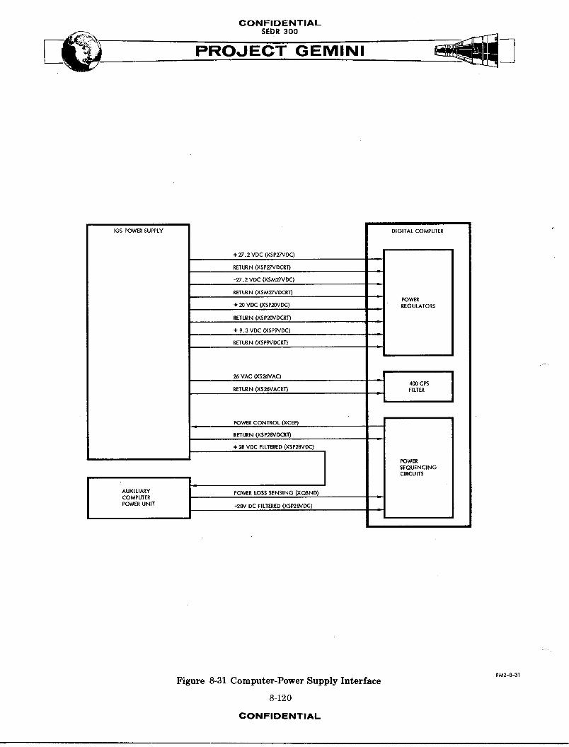
CONFIDENTIAL
PROJECT GEMINI
IGS POWER SUPPLY DIGITAL COMPUTER
+ 27.2 VDC (XSP27VDC)
RETURN (XSP27VDCRT)
-27.2 VDC (XSM2,"VDC)
RETURN (XSM2_/DCRT)POWER
+ 20 VDC (XSP20VDC) REGULATORS
RETURN (XSP2OVDCRT)
÷ 9.3 VDC (XSPgVDC)
RETURN (XSFgVDCRT)
26 VAC (XS26VAC) |4OO CPS JRETURN (XS26VACRT) FILTER
POWER CONTROL (XCEP)
RETURN (XSP28VDCRT)
+ 28 VDC FILTERED (XSP28VDC)
I POWER
SEQUENCINGCIRCUITS
I IAUXILIARY POWER LOSS SENSING (XQSND)COMPUTER •
POWER UNIT _28V DC FILTERED (XSP28VDC)
FM2-8-3!
Figure 8-31 Computer-Power Supply Interface
8-120
CONFIDENTIAL
CONFIDENTIAL
__. $EDR 300
PRO,JGEMINI
Manual Data Insertion Unit (MDIU) (Figure 8-32)
The MDIU can insert into, and/or read out of, the computer up to 99 data words.
It provides the crew _lth a means of updating certain data stored in the com-
puter by inserting new data into the appropriate memory location. It also
provides a capability to verify the data stored in a number of additional memory
locations. Two of the quantities which may be inserted (TR and TX) are trans-
ferred to the Time Reference System by the computer, following insertion.
The MDIU consists of two units : The _anual Data Keyboard (MDK) and the Manual
Data Readout (MDR). The MDK has a keyboard containing lO push-button switches
used during data insertion and readout. To insert data, the pilot always de-
presses seven Data Insert push-button switches ; the first two set up the address
of the computer memory location in which data is to be stored, and the last
five set up the actual data. Each digit inserted is also displayed for verifica-
tion. Following the insertion and verification of the seventh digit, the ENTER
push-button switch is pressed to store the data in the selected memory location.
If verification of any digit cannot be made, the CT.vARpush-button switch is
pressed and the address and data must be set up again. The MDR sequentially
displays for verification the digits inserted by the pilot. This unit can also
be used to recheck quantities stored in the computer memory. This operation is
accomplished by inserting and verifying only the first two (address) digits and
then depressing the READ OUT push-button switch. The selected data is then
displayed for verification. If the pilot attempts to insert data in an invalid
address, attempts to read data out of an invalid address, inserts more than
_ seven digits, or fails to insert a two-digit address prior to depressing the
8-121CONFIDENTIAL
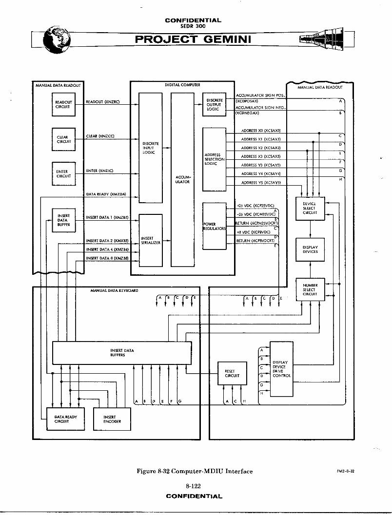
CONFIDENTIAL
PROJECT GEMINI
MANUAL DATA READOUT DIGITAL COMPUTERMANUAL DATA READOUT
READOUT (XNZRC) = ',XCDPOSAX)_,CCUMULATOR SIGN NEG
XCDNEGAX)
i ADDRESS X0 (XCSAX0)
ICLEAR (Y3_4ZCC) = ADDRESS Xl (XCSAXI)
J DISCRETE
INPUT = ADDRESS X2 (XCSAX2)
LOGIC ADDRESS ADDRESS X3 (XCSAX3) ¢:SELECTION
LOGIC ADDRESS Y3 (XCSAY3)
ENTER (XNZIC) . ADDRESS Y4 (XCSAY4)ACCUM-
ULKTOR ADDRESS Y5 (XCSAY5)
DATA READy (XMZDA) _ f ]
+25 VDC (XCP25VDC) DEVICE
__ SELECT
INSERT DATA 1 (XNZR1) -25 VDC (XCM25VDC) CIRCUIT!
POWER _ETURN
_tEGULATORS +B VDC (XCP8VDC)
INSERT DATA 2 (XMX82) INSERT• SERIALIZER RETURN (XCPRVDCRT)
DISPLAyINSERT DATA 4 (XMZB4) DEVICES -
INSERT DATA 8 (XMZBI
NUMBERMANUAL DATA KEYBOARD SELECT
CIRCUIT
INSERT DATA ABUFFERS
BDISPLAy
C DEVICERESET DRIVECIRCUIT D CONTROL
G
H
DATAREADY IN SERTCIRCUIT ENCODER
Figure 8-32 Computer-MDIU Interface EM2-S-32
8-122
CONFIDENTIAL
CONFIDENTIAL$EDR 300
ENTER or READ OUT push-button switch, the seven digits displayed are all zeros
indicating a pilot error.
The following CLD instruction programming is associated with the MDIU interface:
Si6nal Address
X Y
Dataready 1 0
Enter 2 0
Readout 3 0
Clear 4 0
j_- The following PRO instruction programm__ng is associated with the MDIU interface:
Si_n_1 Address
X Y
Digitmagnitudeweighti 0 3
Digit magnitude weight 2 i 3
Digit magnitude weight 4 2 3
Digitmagnitudeweight8 3 3
Reset KIOI, DI02, and DI03 0 4
Displaydevicedrive i 4
DigitselectweightI 0 5
Digit select weight 2 I 5
Digitselectweight2 i 5
Digit select weight 4 2 5
Read MDIU insert data 3 4
8-123
CONFIDENTIAL
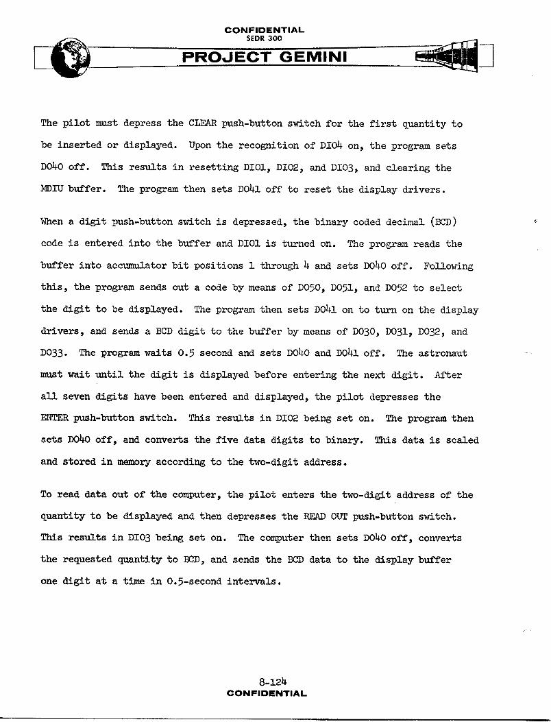
CONFIDENTIAL
PROJECT GEMINI
The pilot must depress the CLEAR push-button switch for the first quantity to
be inserted or displayed. Upon the recognition of DI04 on, the program sets
DO_O off. This results in resetting DI01, DI02, and DI03, and clearing the
MDIU buffer. The program then sets DO41 off to reset the display drivers.
When a digit push-button switch is depressed, the binary coded decimal (BCD)
code is entered into the buffer and DIOI is turned on. The program reads the
buffer into accumulator bit positions 1 through 4 and sets DO40 off. Fo]Sowing
this, the program sends out a code by means of DO50, D051, and D052 to select
the digit to be displayed. The program then sets DO41 on to turn on the display
drivers, and sends a BCD digit to the buffer by means of DO30, DO31, DO32, and
D033. The program waits 0.5 second and sets DO40 and D041 off. The astronaut
must wait until the digit is displayed before entering the next digit. After
all seven digits have been entered and displayed, the pilot depresses the
ENTER push-button switch. This results in DIO2 being set on. The program then
sets DO40 off, and converts the five data digits to binary. This data is scaled
and stored in memory according to the two-digit address.
To read data out of the computer, the pilot enters the two-digit address of the
quantity to be displayed and then depresses the READ OUT push-button switch.
This results in DIO3 being set on. The computer then sets DO40 off, converts
the requested quantity to BCD, and sends the BCD data to the display buffer
one digit at a time in 0.5-second intervals.
8-124CONFIDENTIAL
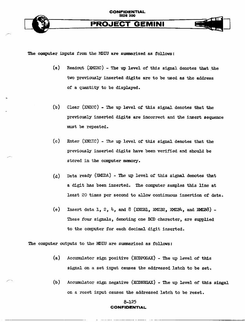
CONFIDENTIAL
__ SEDR300
PRMINI
The computer inputs from the MDIU are sru._arized as follows :
(a) Readout (X_F_RC) - The up level of this signal denotes that the
two previously inserted digits are to be used as the address
of a q_ntity to be displayed.
(b) Clear (XNZCC) - The up level of this signal denotes that the
previously inserted digits are incorrect and the insert sequence
must be repeated.
(c) E-ter (XNZIC) - The up level of this signal denotes that the
previously inserted digits hnve been verified and should be
stored in the computer memory.
(d) Data ready (X_DA) - The up level of this signal denotes that
a digit has been inserted. The computer samples this line at
least 20 times per second to _11ow continuous insertion of data.
(e) Insert data i, 2, 4, and 8 (XNZBI, XMZ_, XMZB4, and XMZBS) -
These four signals, denoting one BCD character, are supplied
to the comi_iter for each decimal digit inserted.
The computer outputs to the MDIU are m_._rized as follows:
(a) Accumulator sign positive (XCDPOSAX) - The up level of this
sign_! on a set input causes the addressed latch to be set.
(b) Accumulator sign negative (XCDNEGAX) - The up level of this singal
on a reset input causes the addressed latch to be reset.
8-125CON I=IDENTIAL
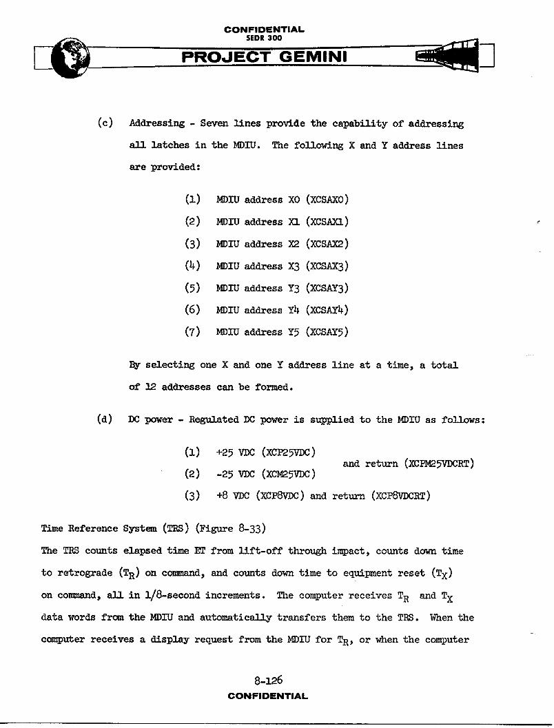
CONFIDENTIAL
_. SEDR300
PROJECT GEMINI
(c) Addressing - Seven lines provide the capability of addressing
,11 latches in the MDI'U. The following X and Y address lines
are provided:
(I) MDIU address XO (XCSAXO)
(2) MDIU address XI (XCSAXI)
(3) MDIU address X2 (XCSAX2)
(_) MDIU address X3 (XCSAX3)
(5) MDIU address Y3 (XCSAY3)
(6) MDIU address Y4 (XCSAY4)
(7) MDIU address Y5 (XCSAY5)
By selecting one X and one Y address line at a time, a total
of 12 addresses can be formed.
(d) DC power - Regulated DC power is supplied to the MDIU as follows:
(1) +25 VOC (XC_SV_)and return (XCPM25VDCRT)
(2) (xeesv )
(3) +8 VDC (XCP8VDC) and return (XCP8VDCRT)
Time Reference System (TRS) (Figure 8-33)
The TRS counts elapsed time ET from lift-off through impact, counts down time
to retrograde (TR) on command, and counts down time to equipment reset (Tx)
on co-_,d, all in i/8-second increments. The computer receives TR and TX
data words from the MDIU and automatieA11y transfers them to the TRS. When the
computer receives a display request from the MDIU for T2, or when the computer
8-126
CONFIDENTIAL
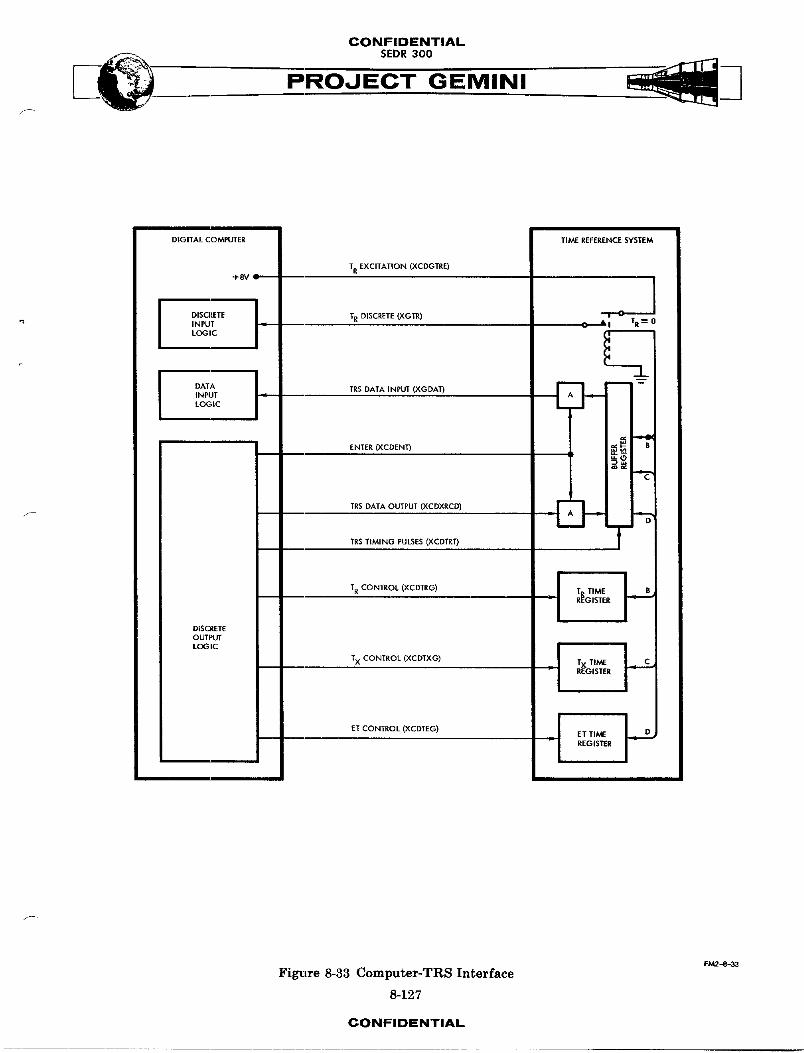
CONFIDENTIAL
PROJECT GEMINIf_/
DIGITAL COMPUTER TIME REFERENCE SYSTEM
TR EXCITATION (XCDGTEE)+SV ---
l 1 IDISCRETE TR DISCRETE (XGTE) "r"OINPUT ,.. C • 3 TR-----"0
LOGICI i ..INPUT .I I A
LOGIC I . .
ENTER(XCDENn m_ _-- ,_
_C"
ITRS DATA OUTPUT (XCDXRCD)
D| | | .
TRS TIMING PULSES (XCDTRT) TI
TR CONTROL (XCDTRG) _ J T TIME I B
REGISTER -_ "
DISCRETEOUTPUT
LOGIC Ij
TX CONTROL (XCDTXG) TX TIME CREGISTER
ET CONTROL (XCDTEG) J ET TI/VEREGISTER
f -
FM2-8-33
Figure 8-33 Computer-TRS Interface
8-127
CONFIDENTIAL
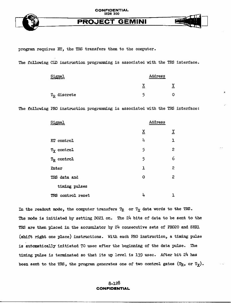
CONFIDENTIALSEDR 300
program requires ET, the TRS transfers them to the computer.
The following CLD instruction programming is associated with the TRS interface.
Si_s Address
X Y
TRdiscrete 5 0
The following PRO instruction progr_mm_ ng is associated with the TRS interface:
Signal Address
X Y
ET control 4 I
Tx control 5 2
TR control 5 6
Enter i 2
TRSdataand 0 2
TRScontrolreset 4 i
In the readout mode, the computer transfers TR or Tx data words to the TRS.
The mode is initiated by setting DO21 on. The 24 bits of data to be sent to the
TRS are then placed in the accu-,tIAtorby 24 consecutive sets of PRO20 and SHRI
(shift right one place) instructions. With each PRO instruction, a timing pulse
is autamatic_11y initiated 70 usec after the beginning of the data p,_1_e. The
timing l_1_e is terminated so that its up level is 1S9 usec. After bit 24 has
been sent to the TRS, the program generates one of two control gates (TR, or TX).
8-128CONFIDENTIAl.
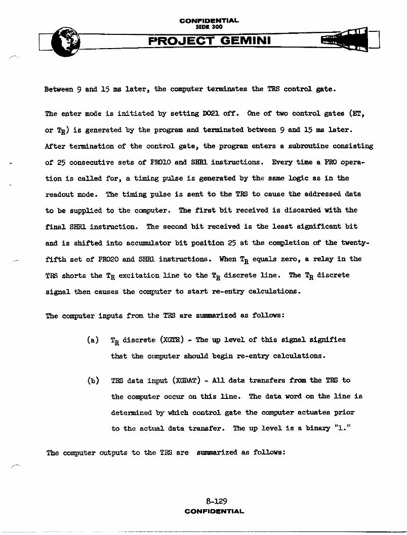
CONFIDENTIAL5EOl 300
PROJ INI
Between 9 and 15 ms later, the computer terminates the TRS control gate.
The enter mode is initiated by setting DO21 off. One of two control gates (ET,
or TR) is generated by the program and ter,_uated between 9 and 15 ms later.
After termination of the control gate_ the program enters a subroutine consisting
- of 25 consecutive sets of PR010 and SHRI instructions. Every time a PRO opera-
tion is called for, a t_m_ng pulse is generated by the same logic as in the
readout mode. The t_m_ ng pulse is sent to the TRS to cause the addressed data
to be supplied to the computer. The first bit received is discarded with the
final SHRI instruction. The second bit received is the least significant bit
and is shifted into accumulator bit position 25 at the completion of the twenty-
..... fifth set of PRO20 and SHRI instructions. When TR eq,,-]s zero, a relay in the
TRS shorts the TR excitation line to the TR discrete line. The TR discrete
signal then causes the computer to start re-entry calculations.
The computer inputs from the TRS are s,-,-_rized as follows:
(a) TR discrete (XGTR) - The up level of this signal signifies
that the computer should begin re-entry calc,,_-tions.
(b) TRS data input (XGDAT) - _11 data transfers from the TRS to
the computer occur on this line. The data word on the line is
determined by which control gate the computer actuates prior
to the act_ml data transfer. The up level is a binary "l."
The computer outputs to the TES are s,mmmrized as fo11_wB:
8-129CONFIDENTIAL.
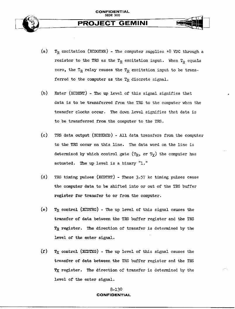
CONFIDENTIALSEDR 300
(a) TR excitation (XCDGTRE) - The computer supplies +8 VDC through a
resistor to the TRS as the TR excitation input. When TR equals
zero, the TR relay causes the TR excitation input to be trans-
ferred to the computer as the TR discrete signal.
(b) Enter (XCDE_f) - The up level of this signal signifies that
data is to be transferred from the TRS to the computer when the
transfer clocks occur. The down level signifies that data is
to be transferred from the computer to the TRSo
(c) TRS data output (XCDXRCD) - All data transfers from the computer
to the TRS occur on this line. The data word on the line is
determined by which control gate (TR, or TX) the computer has
actuated. The up level is a binary "l."
(d) TRS timing p%,S_es (XCDTRT) - These 3.57 kc timing pulses cause
the computer data to be shifted into or out of the TRS buffer
register for transfer to or from the computer.
(e) TR control (XUDTRG) - The up level of this signal causes the
transfer of data between the TRS buffer register and the TRS
TR register. The direction of transfer is determined by the
level of the enter signal.
(f) Tx control (XCDTXG) - The up level of this signal causes the
transfer of data between the TRS buffer register and the TRS
TX register. The direction of transfer is determined by the -
level of the enter signal.
8-130
CONFIDENTIAL
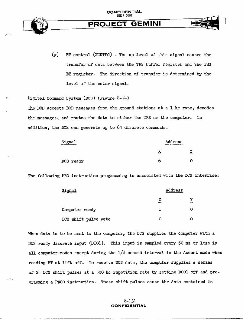
CONFIDENTIAL
•"-. SEDR300 _jj_ ._.__
PROJECT GEMINI
(g) ET control (XCDTEG) - The up level of this signal causes the
transfer of data between the TRS buffer register and the TRS
ET register. The direction of transfer is determined by the
level of the enter signal.
Digital Commnnd System (DCS) (Figure 8-34)
The DCS accepts BCD messages from the ground stations at a 1 kc rate, decodes
the messages, and routes the data to either the TRS or the computer. In
addition, the DCS can generate up to 64 discrete commands.
_Signal Address
X Y
DCSready 6 0
The following PRO instruction programming is associated with the DCS interface:
Signal Address
X Y
Computerready 1 0
DCS shift p_Lse gate 0 0
When data is to be sent to the computer, the DCS supplies the computer with a
DCS ready discrete input (DI06). This input is sampled every 50 ms or less in
all computer modes except during the 1/8-second interval in the Ascent mode when
reading ET at lift-off. To receive DCS data, the computer supplies a series
of 24 DCS shift pulses at a 500 kc repetition rate by setting DOO1 off and pro-
grsm__ng a PROO instruction. These shift pulses cause the data contained in
8-131CONFIDENTIAL
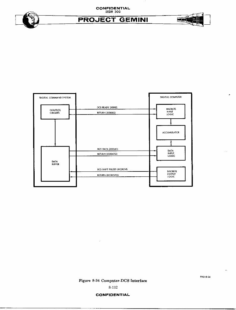
CONFIDENTIAL
PROJECT GEMINI
DIGITAL COMMAND SYSTEM DIGITAL COMPUTER
CONTROL _ DISCRETE
CIRCUITS RETURN (XDRDG) INPUTLOGIC
I ACCUMULATOR
t
DCSDATA_XDDAT_ _J DATA.ETU.NCXDOATG_ _NPUT
LOGIC
DATABUFFER
DISCRETE
RETURN (XCDCSPG) OUTPUTLOGIC
I
FM2-8-34
Figure 8-34 Computer-DCS Interface
8-132
CONFIDENTIAL
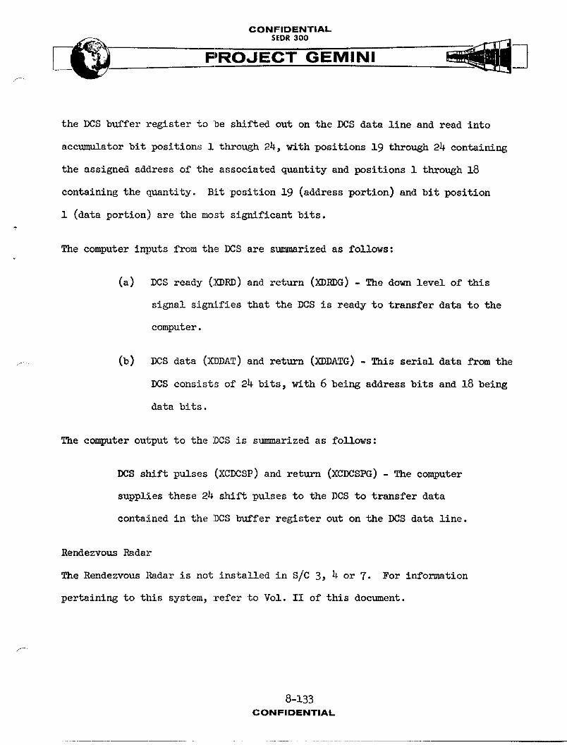
CONFIDENTIAL
PROJECT GEMINI/
the DCS buffer register to "be shifted out on the DCS data line and read into
accumulator bit positions i through 24, with positions 19 through 24 containing
the assigned address of the associated quantity and positions i through 18
containing the quantity. Bit position 19 (address portion) and bit position
i (data portion) are the mo_t significant bits.?
The computer inputs from the DCS are s_]mmarizedas follows:
(a) DCS ready (XDRD) and return (_RDG) - The down level of this
signal signifies that the DCS is ready to transfer data to the
computer.
f (b) DCS data (XDDAT) and return (XDDATG) - This serial data from the
DCS consists of 24 bits, with 6 being address bits and 18 being
data bits.
The computer output to the DCS is s_mmarized as follows:
DCS shift pulses (XCDCSP) and return (XCDCSPG) - The computer
supplies these 24 shift pulses to the DCS to transfer data
contained in the DCS buffer register out on the DCS data line.
Rendezvous Radar
The Rendezvous Radar is not installed in S/C 3, _ or 7. For information
pertaining to this system, refer to Vol. II of this document.
f-
8-133CONFIDENTIAL
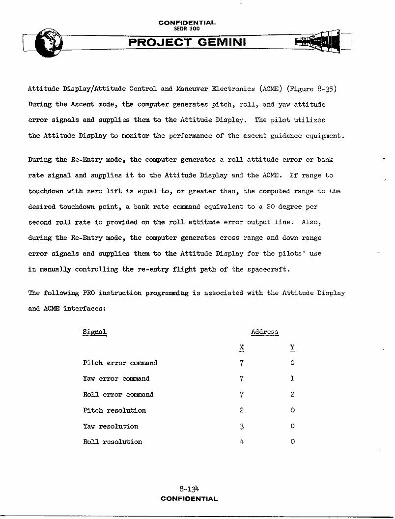
CONFIDENTIAL
PROJECT GEMINI
Attitude Display/Attitude Control and Maneuver Electronics (ACME) (Figure 8-35)
During the Ascent mode, the computer generates pitch, roll, and yaw attitude
error signals and supplies them to the Attitude Display. The pilot utilizes
the Attitude Display to monitor the performance of the ascent guidance equipment.
During the Re-Entry mode, the computer generates a roll attitude error or bank
rate signal and supplies it to the Attitude Display and the ACME. If range to
touchdown with zero lift is equal to, or greater than, the computed range to the
desired touchdown point, a bank rate command equivalent to a 20 degree per
second roll rate is provided on the roll attitude error output line. Also,
during the Re-Entry mode, the computer generates cross range and down range
error signals and supplies them to the Attitude Display for the pilots' use
in manus]ly controlling the re-entry flight path of the spacecraft.
The following PRO instruction progrsmm_ug is associated with the Attitude Display
and AC_ interfaces:
Signal Address
X Y
Pitch error co_mmnd 7 O
Yawerrorcomm_ud 7 1
Roll error command 7 2
Pitch resolution 2 0
Yawresolution 3 0
Rollresolution 4 0
8-134CONFIDENTIAL
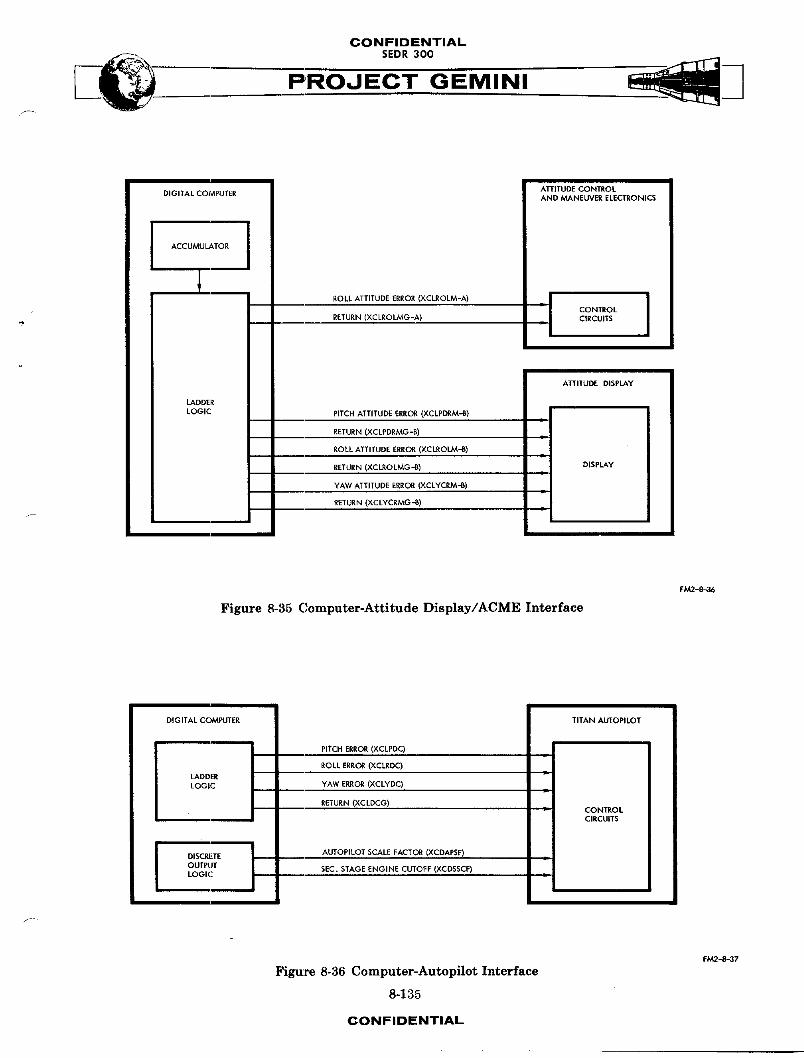
CONFIDENTIAL
PROJECT GEMINI
ATTITUDE CONTROLDIGITAL COMPUTER AND MANEUVER ELECTRONICS
ACCUMULATOR J
1ROLL ATTITUDE ERROR (XCLROLM-A) J
IRETURN (XCLROLMG-A)
ATI'ITUDE DISPLAY
LADDER
LOGIC PITCH ATTITUDE ERROR (XCLPDRM-B)•I
RETURN (XCLPDRMG-B) • I
ROLL ATTITUDE ERROR (XCLROLM-B)ml
RETURN (XCLROLMG-B) DISPLAYml
YAW ATTITUDE ERROR (XCLYCRM'B)L I
RETURN (XC LYCRMG -_) ,|
Fi_2-_36
Figure 8-35 Computer-Attitude Display/ACME Interface
IDIGITAL COMPUTER _ TITAN AUTOPILOT
ROLL ERROR (XCLRDC) I , ILADDERLOGIC YAW ERROR (XCLYDC)
RETURN (XC LDCG) IsL CONTROLCIRCUITS
I DISCRETE I AUTOPILOT SCALE FACTOR (XCDAPSF) • I
OUTPUTSEC. STAGE ENGINE CUTOFF (XCDSSCF)
LOGIC • I
I
i
FM2-8-37
Figure 8-36 Computer-Autopilot Interface
8-135
CONFIDENTIAL
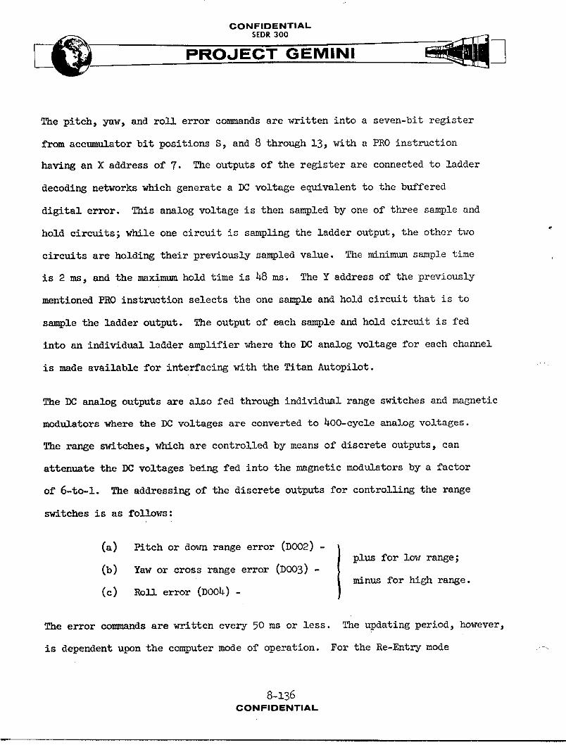
CONFIDENTIAL
SEDR300 _._
The pitch, yaw, and roll error commands are written into a seven-bit register
from accumulator bit positions S, and 8 through 13, with a PRO instruction
having an X address of 7. The outputs of the register are connected to ladder
decoding networks which generate a DC voltage equivalent to the buffered
digital error. This analog voltage is then sampled by one of three sample and
hold circuits; while one circuit is sampling the ladder output, the other two
circuits are holding their previously sampled value. The minimum sample time
is 2 ms, and the maximum hold time is 48 ms. The Y address of the previously
mentioned PRO instruction selects the one sample and hold circuit that is to
sample the ladder output. The output of each sample and hold circuit is fed
into an individual ladder amplifier where the DC analog voltage for each channel
is made available for interfacing with the Titan Autopilot.
The DC analog outputs are also fed through individual range switches and magnetic
modulators where the DC voltages are converted to 400-cycle analog voltages.
The range switches, which are controlled by means of discrete outputs, can
attenuate the DC voltages being fed into the magnetic modulators by a factor
of 6-to-1. The addressing of the discrete outputs for contro]_]__ the range
switches is as follows:
(a) Pitch or down range error (DOO2) -plus for low range;
(b) Yaw or cross range error (DOO3) -minus for high range.
(c) Roll error (DO04)-
The error commands are written every 50 ms or less. The updating period, however,
is dependent upon the computer mode of operation. For the Re-Entry mode ....
8-136CONFIDENTIAL
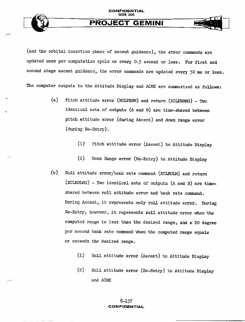
CONFIDENTIAL
PROJECT GEMINI
(and the orbital insertion phase of ascent guidance), the error commands are
updated once per computation cycle or every 0.5 second or less. For first and
second stage ascent guidance, the error commands are updated every 50 ms or less.
The computer outputs to the Attitude Display and ACME are summarized as follows:
(a) Pitch attitude error (XCLPDRM) and return (XCLPDRMG) - Two
identical sets of outputs (A and B) are time-shared between
pitch attitude error (during Ascent) and down range error
(during Re-Entry).
(i) Pitch attitude error (Ascent) to Attitude Display
(2) Dovn Range error (Re-Entry) to Attitude Display
(b) Ro]] attitude error/bank rate command (XCLROLM) and return
(XCLROLMG) - Two identical sets of outputs (A and B) are time-
shared between roll attitude error and bank rate command.
During Ascent, it represents only roll attitude error. During
Re-Entry, however, it represents roll attitude error when the
computed range is less than the desired range, and a 20 degree
per second bank rate command when the computed range equals
or exceeds the desired range.
(1) Roll attitude error (Ascent) to Attitude Display
(2) Roll attitude error (Re-Entry) to Attitude Display
_ andACME
8-137CONFIDENTIAL
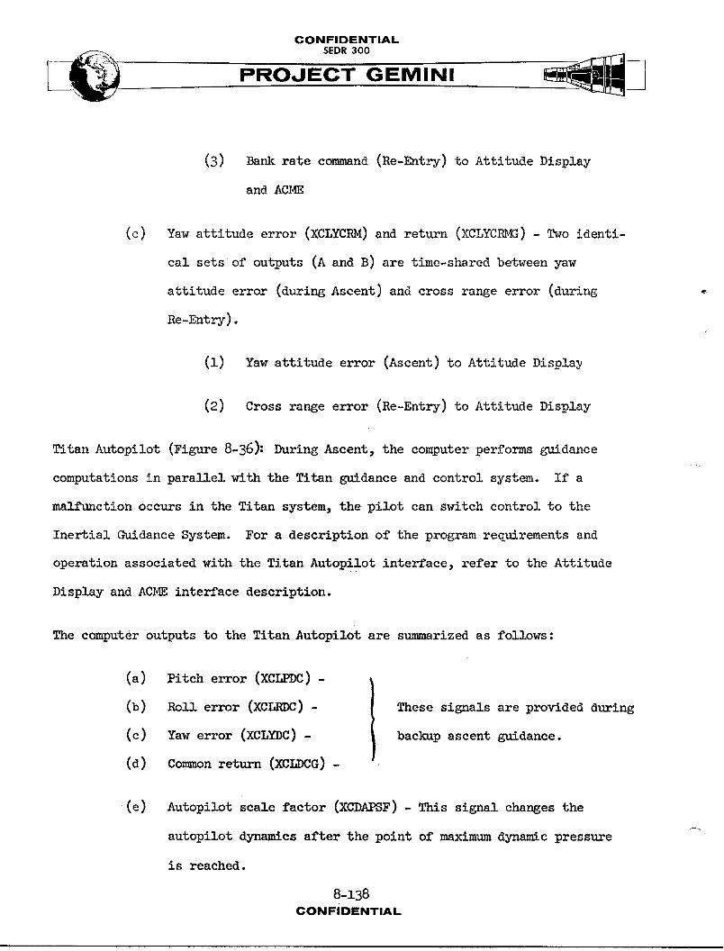
CONFIDENTIALSEDR 300
(3) Bank rate command (Re-Entry) to Attitude Display
and ACME
(c) Yaw attitude error (XCLYCRM) and return (XCLYCRMG) - Two identi-
cal sets of outputs (A and B) are time-shared between yaw
attitude error (during Ascent) and cross range error (during _
Re-Entry).
(1) Yaw attitude error (Ascent) to Attitude Displa_
(2) Cross range error (Re-Entry) to Attitude Display
Titan Autopilot (Figure 8-36): During Ascent, the computer performs guidance
computations in parallel with the Titan guidance and control system. If a
mnlfunction occurs in the Titan system, the pilot can switch control to the
Inertial Guidance System. For a description of the program requirements and
operation associated with the Titan Autopilot interface, refer to the Attitude
Display and ACME interface description.
The computer outputs to the Titan Autopilot are s_mm_rized as follows:
(a) Pitch error (XCLPDC)-
(b) Roll error (XCLRDC) - These signals are provided during
(c) Yaw error (XCLYDC)- backup ascent guidance.
(d) Common return (XCLDCG) -
(e) Autopilot scale factor (XCDAPSF) - This signal changes the
autopilot dynamics after the point of maximum dynamic pressure
is reached.
8-138CONFIDENTIAL
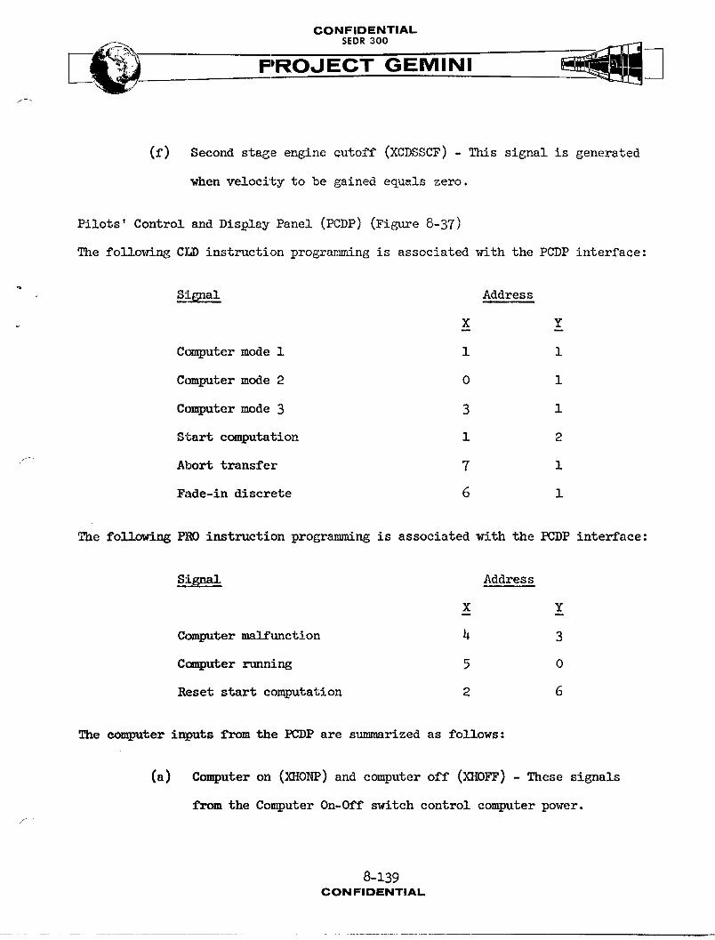
CONFIDENTIAL
PROJECT GEMINI
(f) Second stage engine cutoff (XCDSSCF) - This signal is generated
when velocity to be gained equals zero.
Pilots' Control and Display Panel (PCDP) (Figure 8-37)
The following CLD instruction programming is associated with the PCDP interface:
,Si6nal Address
X Y
Computer mode 1 1 1
Computer mode 2 0 1
Computer mode 3 3 1
Start computation 1 :9
f Abort transfer 7 i
Fade-indiscrete 6 1
The following PRO instruction programming is associated with the PCDP interface:
Signal Address
X Y
Computer malfunction 4 3
Computer running 5 0
Reset start computation 2 6
The computer inputs from the PCDP are summarized as follows:
(a) Computer on (_G_ONP)and computer off (XHOFF) - These signals
from the Computer On-Off switch control computer power.
8-139CONFIDENTIAL
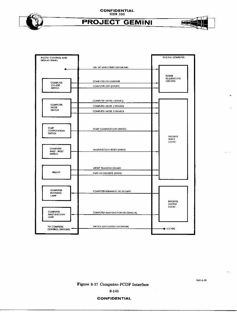
CONFIDENTIAL
PROJECT GEMINI
PI LOTS' CONTROL AND DIGITAL COMPUTERDISPLAY PANEL
SEQUENCING
ON'OFF COMPUTER OFF (XHOFF)SWITCH
COMPUTER MODE I (XHMSI)
COMPUTER COMPUTER MODE 2 (XHMS2)MOD£
SWITCH COMPUTER MODE 3 (XHMS3)
J START START COMPUTATION (XHSTC)
COMPUTATION
SWITCH DISCRETEINPUTLOGIC
.V.,ALF. RESETSWITCH
RELAYS FADE-IN DISCRETE(XHSFI)
I COMPUTER l COMPUTER RUNNING (XCDCOMP)
RUNNINGLAMP
DISCRETEOUTPUTLOGIC
I
COMPUTER J COMPUTER MALFUNCTION (XCDMAL-A)
MALFUNC'_ION j -"
LAMP
TO COMPUTER SWITCH EXCITATION (XCDHSME)2 +SVDC
CONTROL SWITCHES "
FM2-8-39
Figure 8-37 Computer-PCDP Interface
8-140
CONFIDENTIAL
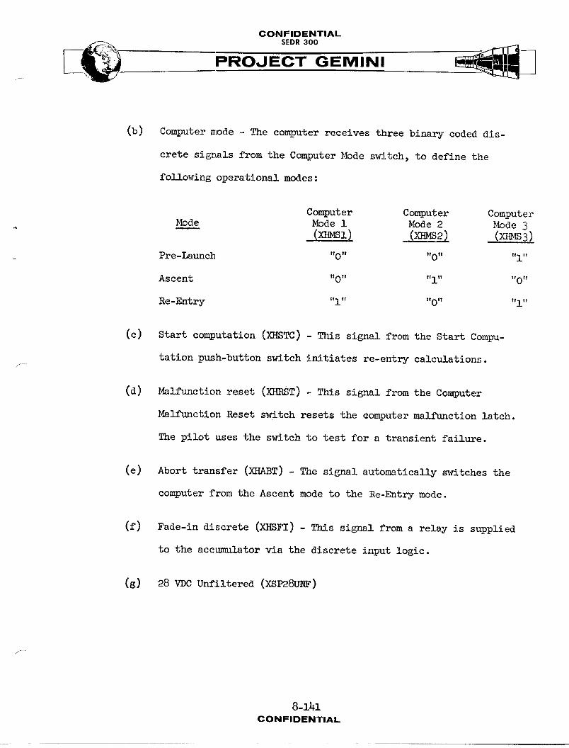
CONFIDENTIAL
PROJECT GEMINI
(b) Computer mode - The computer receives three binary coded dis-
crete signals from the Computer Mode s_riteh,to define the
following operational modes :
Computer Computer Computer. Mode Modei Mode2 Mode3
(X_Sl) ,(X_S2) .,(X_S3)
Pre-Launch "0" "0" "i"
Ascent "0" "i" "0"
Re-Entry "i" "0" "i"
(c) Start computation (XHSTC) - This signal from the Start Compu-
tation push-button switch initiates re-entry calculations.,f
(d) Malfunction reset (XKR T) - This signal from the Computer
Malfunction Reset switch resets the computer malfunction latch.
The pilot uses the switch to test for a transient failure.
(e) Abort transfer (XHABT) - The signal automatically m¢itehes the
computer from the Ascent mode to the Re-Entry mode.
(f) Fade-in discrete (XHBFI) - This signal from a relay is supplied
to the accumulator via the discrete input logic.
(g) 28 VDC Unfiltered (XSP28UHF)
8-14lCONFIDENTIAL
CONFIDENTIAL
PROJECT GEMINI
The computer outputs to the PCDP are s_mm_rized as foll_s:
(a) Computer running (XCDCOMP) - This program-controlled signal
lights the Computer lhnuuinglamp which is used as foll_Is:
(1) Pre-Launch: The Computer Running lamp remains off
during this mode, except during mission simulation
when its operation is governed by the mode being
simulated.
(2) Ascent: The Computer Running lamp turns on follo_ng
Inertial Platform release. The lamp remains on for
the duration of the mode, and then turns off.
NOTE
For a description of lamp opera-
tion during the Catch-up and
Rendezvous modes, refer to Vol. II
of this document.
(3) Re-Entry: The Computer Running lamp lights when the
Start Computation push-button s_tch is depressed
or when time to start re-entry calculations is
equal to zero. The lamp remains on for the duration
of the mode, and then turns off.
8-142CONFIDENTIAL
CONFIDENTIAL
SEDR300
PROJECT GEMINI
(b) Computer m_llfunction (XCDMAL-A) - This signal turns on the Com-
puter Malflmction lamp. Either the computer diagnostic program,
a built-in timing check, or an AGE command actuates the signal.
(c) Switch excitation (XCDHSME) - This DC excitation is supplied
to the Computer Mode switch, the Start Computation switch, and
the Malfunction Reset switch.
Incremental Velocity Indicator (IVI) (Figure 8-38)
The IVI contains three incremental velocity counters that display velocity
increments along the spacecraft (body) axes.
_ Power is applied to the IVI whenever the computer is turned on. During the first
30-second period (or less) following the application of power, the M auto-
matically references its counters to zero. After this period, the M is capable
of recognizing computer signals.
The IVI counters can be set manually by means of control knobs on the front of
the unit, or they can be set automatically by the computer. After the counters
are initially set, they are driven by incremental velocity pulses from the com-
puter. These pulses are used to update the indications displayed by the counter.
The computer can set the individual counters to zero by providing a 20 usec
pulse on each of three set zero lines. A feed-back signal, denoting zero counter
position, permits the computer to test for the proper counter reference prior
to the insertion and display of a computed velocity increment.
8-143CONF|OENTIAL
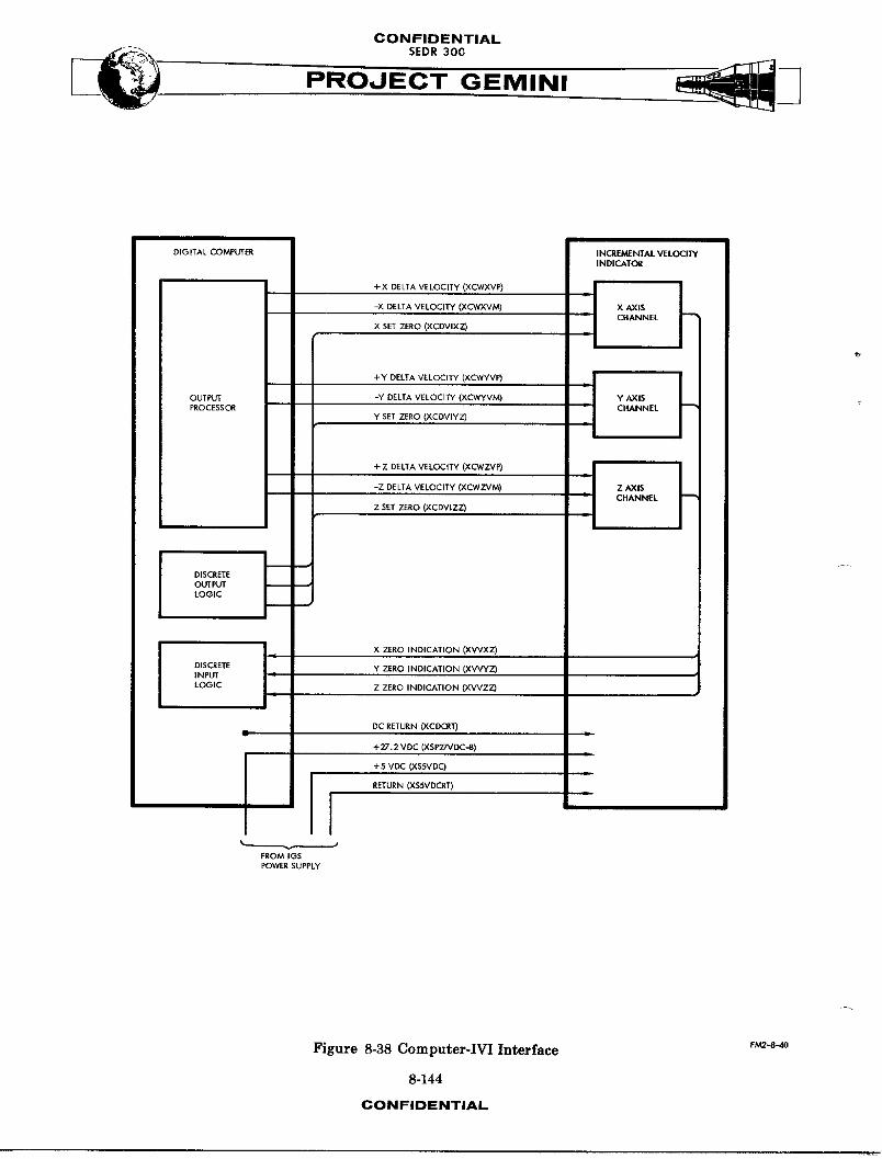
CONFIDENTIAL
PROJECT GEMINI
DIGITAL COMPUTER INCREMENTAL VELOCITYIND|CATOR
+x_LEA,,E,OC,TY_XCWXVRI--'_1
-X DELTA VELOCITY (XCWXVM) - X AXIS
X SET ZERO (XCDVIXZ) _ CHANNEL
+YDELTAVELOC,_(XCWVVP) J . I
PROCESSC_ CHANNELY SET ZERO (×CDVIY2)
-Z DELTA VELOCITY (XCWZVM) Z_lSCHANNEL
Z SET ZERO (XCDVIZZ)
DISCRETEOUTPUTLOGIC
I I xZERo,ND,CAT,ON_XWXZ,
°+CRETE1 _ZE,O,NO,_AT,O__X_INPUT
LOGIC Z ZERO INDICATION (XWZZ)
DC RETURN (XCDCR'T)
+27.2 VDC (XSP27VDC,-B)
+5 VDC (XSSVDC)1
RETURN (XSSVDCRT)
FROM IGSPOWER SUPPLY
Figure 8-38 Computer-IVI Interface F_-8_
8-144
CONFIDENTIAL
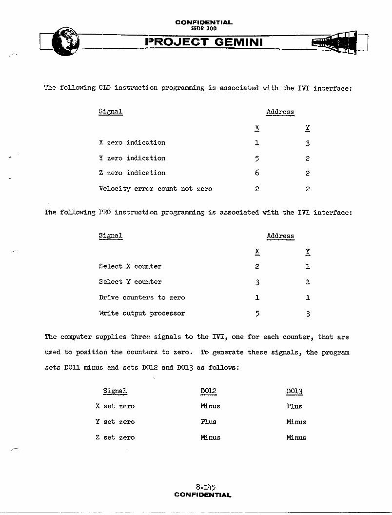
CONFIDENTIAL
PROJECT GEMINI
The following CLD instruction programming is associated with the IVI interface:
Signal Address
X Y
X zeroindication 1 3
Y zeroindication 5 2
Z zero indication 6 2
Velocity error count not zero 2 2
The following PRO instruction progremm_ng is associated with the IVI interface:
Signal Address
X Y
Select X couz_er 2 1
SelectY cour_er 3 1
Drivecounterstozero 1 1
Writeoutputprocessor 5 3
The computer supplies three signals to the IVI, one for each counter, that are
used to position the counters to zero. To generate these signals, the program
sets DOll minus and sets DO12 and DO13 as fo!lows:
Signal DO12 DOIB
X setzero Minus Plus
Y setzero Plus Minus
Z setzero Minus Minus
j_
8-145CONFIDENTIAL
CONFIDENTIAL_._:-_._ SEDR300
The IVI provides three feed-back signals to the computer (DI31, DI25_ and DI26)
to indicate that the counters are zeroed. The program tests the individual
counters for zero position before attempting to drive them to zero.
The output processor provides a timed output to the IVI that represents velocity
increments along the spacecraft axes. One output channel (phase 2) on the
delay line is time-shared among the X, Y, and Z counters. Incremental velocities
(in two's-complement form) are written on the delay line duringphase 2 from
accumulator bit positions S, and 1 through 12. Discrete outputs DO12 and DO13,
which are set no more than 1 ms before the PRO35 operation, select the proper
velocity signal as follows:
Si6nal DO12 DO13
X velocity Minus Plus
Y velocity Plus Minus
Z velocity Minus Minus
Once data is written on the delay line, the output of the delay line is sensed
for data duringbit t_mes BTlthroughBTl2. Any bit sensed during this time
indicates the presence of data which is then gated into a buffer along with the
sign bit (BTI3) during phase 2. This buffer is sampled approximately every
21.5 ms and a pulse is generated if the buffer is set either plus or minus.
During this same time, an update cycle is initiated and a count of one is
either added to or subtracted from the delay line data to decrease the magni-
tude by a count of one. If the buffer is set to zero during the update cycle,
the data on the delay line is recirculated without affecting its magnitude.
8-146
CONFIDENTIAL
CONFIDENTIAL
__ SEDR300
PROJECT GEMINI/
The zero output of the buffer is addressed as D122. _en this discrete input
is off, velocity data has been counted down to zero and the next velocity can
be processed.
The computer inputs from the IVI are summarized as follows:
(a) X zero indication (XVVXZ) - The down level signifies that the
X channel of the IVI is at the zero position.
(b) Y zero indication (XVVYZ) - The down level signifies that the
Y channel of the IVI is at the zero position.
(c) Z zero indication (XVVZZ) - The down level signifies that the
Z channel of the IVI is at the zero position.
The computer outputs to the IVI are summarized as follows:
(a) +X delta velocity (XCWXVP) - The up level denotes that the
X channel should change by one foot per second in the fore
direction.
(b) -X delta velocity (XC_C_M) - _le up level denotes that the
X channel shoIhld change by one foot per second in the aft direc-
tion.
(c) X set zero (XCDVIXZ) - The up level drives the X channel to
the zero position.
f--
8-147CONFIDENTIAL

CONFIDENTIAL
PROJECT GEMINI
(d) +Y delta velocity (XC_DYVP)- The up level denotes that the Y
channel should change by one foot per second in the right
direction.
(e) -Y delta velocity (XCWYVM) - The up level denotes that the Y
channel should changeby one foot per second in the left
direction.
(f) Y set zero (XCDVIYZ) - The up level drives the Y channel to the
zero position.
(g) +Z delta velocity (XCWZVP) - The up level denotes that the Z
clmnnel should change by one foot per second in the do_n
direction.
(h) -Z delta velocity (XCWZVM) - The up level denotes that the Z
channel should change by one foot per second in the up direc-
tion.
(i) Z set zero (XCDVIZZ) - The up level drives the Z channel to
the zero position.
Instrumentation System (IS) (Figure 8-39)
The computer is interfaced with the Multiplexer Encoder Unit (MEU) and the
Signal Conditioning Equipment (SCE) of the IS. Continuous analog data is pro-
vided to the SCE and stored digital quantities are sent upon request to the
MEU.
8-148CONFIDENTIAL

CONFIDENTIAL
_.__ SEDR300
PROJECT GEMINI
DIGITAL COMPUTER INSTRUMENTATIONSYSTEM
PLTCHERROR (XCLPMBD)
e. RETURN (XCLPMBDG)
ROLL ERROR (XCLRMBD)
LADDERLOGIC RETURN (XCLR,V,SDG)
YAW ERROR (XCLYMSD)
RETURN (XCLYMSDG)
I POWER I COMPUTER OFF (XCEOFFD)
SEQUENCING SIGNALCIRCUITS CONDITIONING
EQUIPMENT
COMPUTER MALFUNCTION (XCDMALD)
SEC. STAGE ENGINE CUTOFF (XCDSSCFT)
COMPUTER MODE I (XCDMSID)
COMPUTER MODE 2 (XCDMS2D)
COMPUTER MODE 3 (XCDMS3D)
+27.2 VDC (XCDP27D)
DISCRETE + 9.3VDC {XCDP9D)OUTPUTLOGIC
iS SHIFT PULSES (XCDASSP)
RETURN (XCDASS'_)
IS DATA (XCDASD)
RETURN (XCDASDG)
IS REQUEST EXCIT. (XCDTRQL=) MULTIPUEXER+8VDC _" ENCODER
IS DATA SYNC EXCIT. (XCDTDSE)+SVDC "-
J m_J IS REQUEST (XTRQ)
DISCRETE
INPUT IS DATA SYNC (XTDS)LOGIC
Figure 8-39 Computer-IS Interface
8-149
CONFIDENTIAL
CONFIDENTIAL
SEDR300
PROJECT GEMINI
Certain computer data, as described below, is continually made available to the
SCE. The SCE conditions this data for multiplexing and analog-to-digital con-
version by the MEU.
(a) Computer modes - The mode signals transmitted to the computer
are monitored to determine that the computer was in the correct
mode for a particular operational mission phase.
(b) Computer input power - The 27.2 VDC and 9-3 VDC inputs supplied
to the computer by the IGS Power Supply are monitored via the
computer.
(c) Computer off - The output of the off position of the Computer
On-Off switch is monitored via the computer. (S/C B)
(d) Computer ru_n_ng - The computer running discrete output is
monitored and recorded (S/C 4 and 7)
(e) Computer malfunction - The computer malfunction discrete output
is monitored and recorded.
(f) Attitude errors: The pitch, yaw, and roll AC analog attitude
errors are monitored and recorded.
_enty-one data word locations in the computer memory are allocated for the
storage of IS data. Data stored in these locations is dependent upon the com-
puter mode of operation.
The following CLD instruction programming is associated with the IS interface:
8-150CONFIDENTIAL
CONFIDENTIALSEDR300
Signal Address
X Y
IS request 7 0
ISsync 2 1
The following PRO instruction programming is associated with the IS interface:
Signal Address
X Y
IScontrolgate 0 1
Every 50 ms or less, the computer program tests the IS request discrete input
F (DIG[). If the discrete input is tested minus, the IS sync discrete input
(DI32) is tested as follows:
(a) DII2 minus - The program stores current specified values, accord-
ing to the computer mode, in an IS memory buffer of 21 locations.
The contents of the first buffer location are placed in the
accumulator so that the sign position of the data word corres-
ponds to the sign position of the accumulator. Then a PRO10
instruction is given. This instruction causes the information
contained in accumulator bit positions S, and 1 through 23 to
be supplied to the IS. Twenty-four shift pulses are also
supplied to the IS.
(b) DI12 plus - An IS program counter is incremented by one and
the contents of the next sequential buffer location are placed
8-151CONFIOE[NTIAL
CONFIDENTIALSEDR 300
in the accunn11_tor and sent to the IS via PROI0 instructions.
Subsequent IS requests advance the program counter until all
21 instrumentation quantities are transmitted.
The computer inputs from the IS are summarized as foil ows :
(a) IS request (XTRQ) - An up level on this line signifies that
the IS requires a computer data word. The word is transferred
from the computer within 75 ms of the request. Requests can
occur at rates up to l0 times per second.
(b) IS data sync (XTDS) - An up level on this line signifies the
beginning of the IS data transfer operation.
The computer outputs to the IS are summarized as fo_sows :
(a) IS shift pulses (XCDASSP) and return (XCDASSPG) - This series
of 24 pulses causes IS data to be transferred to the IS buffer.
(b) IS data (XCDASD) and return (XCDASDG) - These 24 bits of data
are transferred in synchronism with the IS shift pulses.
(c) IS request excitation (XCDTRQE) - This +8 VDC signal is the
excitation for the IS request signal.
(d) IS data sync excitation (XCDTDSE) - This +8 VDC signal is the
excitation for the IS data sync signal.
8-].52CONFIDENTIAL

CONFIDENTIALSEDR 300
PR-"-E'CGEMI NI
(e) Monitored signals - The following signals are supplied to the
IS for monitoring purposes :
(1) ]Pitch error (XCLPMBD) and return (XCLPMBDG)
(2) Roll error (XCLP_3D) and return (XCLRMBDG)
(3) Yaw error(XCLY_RD)and return(XCLYMBDG)
(4) Computer off (XCEOFFD)
(5) Computer malfunction (XCDMALD)
(6) Second stage engine cutoff (XCDSSCFT)
(7) Computer mode 1 (XCD_lD)
(8) Computer mode 2 (XCD_2D)
f (9) Computer mode 3 (XCDMS3D)
(10) +27.2VDC(XCDP27D)
(11) +9.3VDC (XCDP9D)
Aerospace Ground Equipment (AGE) (Figure 8-40)
The AGE determines spacecraft-installed computer status by being able to read
and display the contents of any memory location, initiate and terminate marginal
tests of the memory timing, and command the computer to condition the computer
malfunction circuit. These tests are accomplished by a hard-wired computer/
AGE data link.
In conjunction with a voice li_ to the spacecraft, the AGE can control the
various computer modes of operation to determine the status of the computer and
its interfaces. To aid in localizing failures, the AGE monitors the following
computer signals :
8-153CONFIDENTIAL
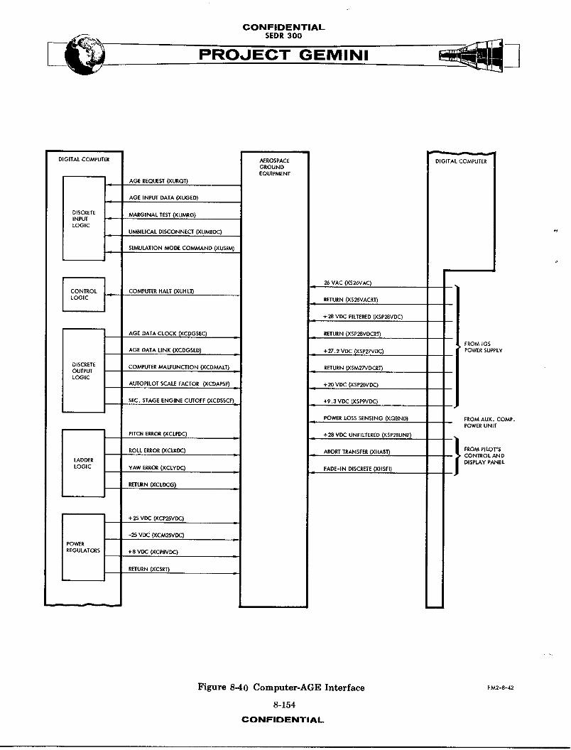
CONFIDENTIAL
s.o.ooPROJECT GEMINI
DIGITAL COMPUTER AEROSPACE DIGITAL COMPUTERGROUNDEQUIPMENT
AGE REQUEST (XURQT)
+ AGE INPUT DATA (XUGED)
DISCRETE MARGINAL TEST (XUMEG)iNPUTLOGIC
UMBILICAL DISCONNECT (XUMBDC)
SIMULATION MODE COMNL_ND (XUSIM)
J I • 26 VAC (XS26VAC) •
CONTROL COMPUTER HALT (XUHL1)
LOGIC _ - RETURN (XS26VACRT)
+28 VDC FILTERED (XSP28VDC)
AGE DATA CLOCK (XCDGSEC) RETURN (XSP28VDCRT)
, PROM IGSAGE DATA LINK (XCDGSED) - +27.2 VDC (XSP27VDC) POWER SUPPLY
DISCRETE COh_UTER MALFUNCTION (XCDMALT) RETURN (XSM27VDCRT)OUTPUTLOGIC
AUTOPILOT SCALE FACTOR (XCDAPSF) +20 VDC (XSP20VDC)
SEC. STAGE ENGINE CUTOFF (XCDSSCF 1 +9.3 VDC (XSP9VDC)
POWER LOSS SENSING (XQBND) FROM AUX. COMP.POWER UNIT
PITCH ERROR(XCLPDC) +28 VDC UNFILTERED (XSP28UNF)
ROLL ERROR (XCLRDC) ABORT TRANSFER (XHABT)i i j_.o_.,_,_
CONTROL ANDLADDER DISPLAY PANEL
LOGIC YAW ERROR (XCLYDC) FADE-IN DISCRETE (XHSFI)
RETURN (XCLDCG)
I +25 VDC _CP25VDC)
-25 VOC ('XCM2_.,DC)
POWER
REGULATORS +8 VDC (XCPSVDC) m
RETURN (XCSRT)
Figure 8-40 Computer-AGE Interface EMR-S-42
8-154
CONFIDENTIAL

CONFIDENTIAL-_ SEDR 300
(a) All input and output voltages
(b) Second stage engine cutoff
(c) Autopilot scale factor
(d) Roll error comm_nd
(e) Yaw error comm_nd (to Titan Autopi!ot)
(f) Pitch error command
(g) Computer ma_unction
In addition, the AGE provides two hard-wired inputs to the computer to reset
the malfunction circuit and half the computer and to force a marginal check
of the memory t_m_ng. Early and late strobing of the memory is effected using
the computer/AGE data link.f •
The following CI_) instruction programming is associated with the AGE interface:
Signal Address
X Y
AGErequest 2 3
AGEinputdata 7 2
Simulationmode command 4 2
Umbilicaldisconnect 6 3
The following PRO instruction programming is associated with the AGE interface:
8-155CONFIDENTIAL
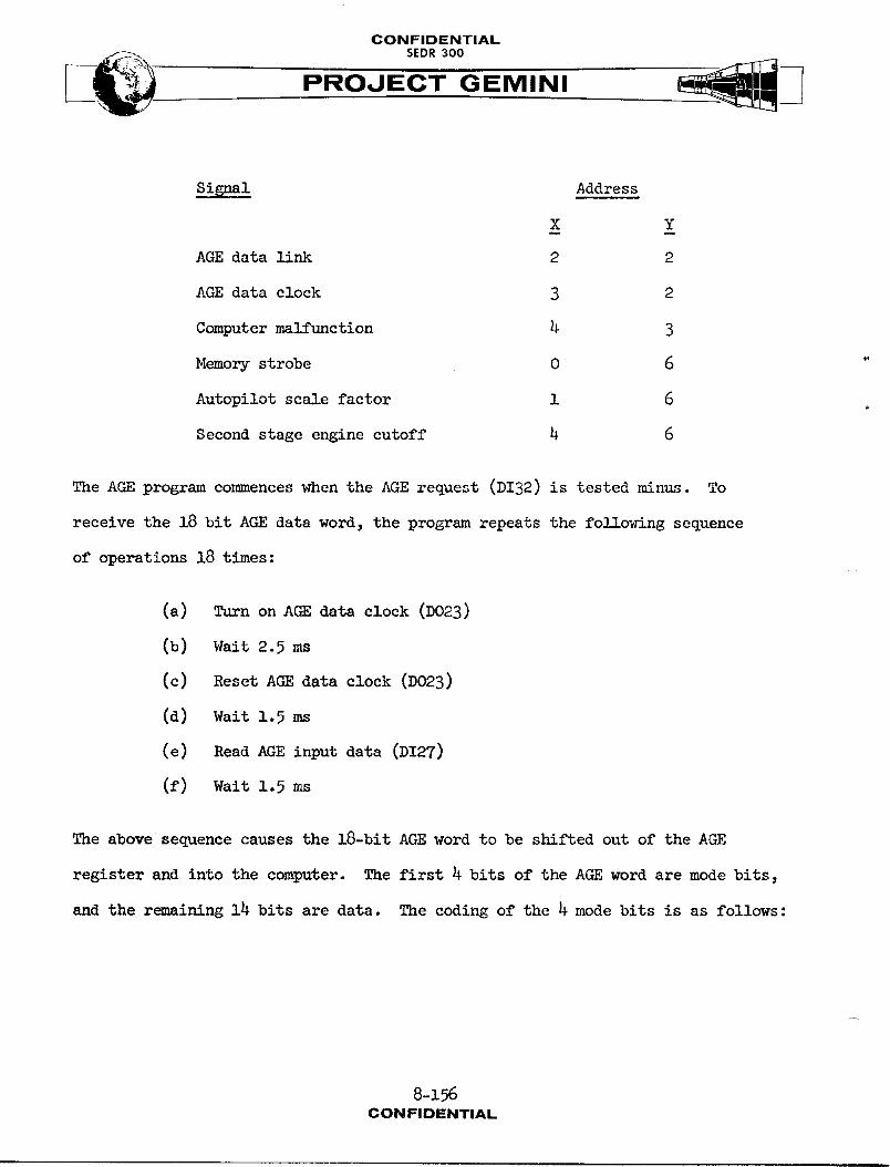
CONFIDENTIAL
.o,ooPROJECT GEMINI
Signal Address
X Y
AGE data link 2 2
AGE data clock 3 2
Computer malfunction 4 3
Memory strobe 0 6
Autopilot scale factor 1 6
Second stage engine cutoff 4 6
The AGE program commences when the AGE request (DI32) is tested minus. To
receive the 18 bit AGE data word, the program repeats the following sequence
of operations 18 times:
(a) Turn on AGE data clock (D023)
(b) Wait 2.5 ms
(c) Reset AGE data clock (D023)
(d) Wait 1.5 ms
(e) Read AGE input data (DI27)
(f) Walt 1.5 ms
The above sequence causes the 18-bit AGE word to be shifted out of the AGE
register and into the computer. The first 4 bits of the AGE word are mode bits,
and the r_m_ining 14 bits are data. The coding of the 4 mode bits is as follows:
8-1%CONFIDP'NTIAL
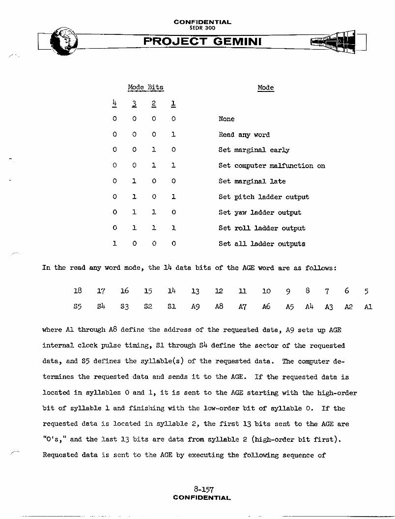
CONFIDENTIAL
PROJECT GEMINI
ModeBits Mode
0 0 0 0 None
0 0 0 1 Read any word
0 0 1 0 Set marginal early
0 0 i I Set computer malfunction on
0 1 0 0 Setmarginallate
0 I 0 i Set pitch ladder output
0 1 1 0 Set yaw ladderoutput
0 1 1 1 Set roll ladderoutput
1 0 0 0 Set all ladderoutputs
/
In the read any word mode, the 14 data bits of the AGE word are as follows:
18 17 16 115 14 13 12 ii i0 9 8 7 6 5
S5 $4 $3 S2 Sl A9 A8 A7 A6 A5 A4 A3 A2 A1
where A1 through A8 define the address of the requested data, A9 sets up AGE
internal clock pulse timing, S1 through $4 define the sector of the requested
data, and $5 defines the syllable(s) of the requested data. The computer de-
termines the requested data and sends it to the AGE. If the requested data is
located in syllables 0 and l, it is sent to the AGE starting with the high-order
bit of syllable 1 and finishing with the low-order bit of syllable O. If the
requested data is located in syllable 2, the first 13 bits sent to the AGE are
t|
"O's, and the last 13 bits are data from syllable 2 (high-order bit first).
'_ Requested data is sent to the AGE by executing the following sequence of
8-157CON FIDENTIAL

CONFIDENTIAL
PROJECT GEMINI
operations 26 times. There is a delay of 4.5 ms between resetting clock 18
and setting clock 19.
(a) Set AGE data link (DO22) from accumulator sign position
(b) Turn on AGE data clock (DO23)
(c) Wait 2.5 ms
(d) Reset AGE data clock (DO23)
(e) Wait 2 ms
(f) Reset AGE data link (DO22)
(g) Wait 1 ms
In the set marginal early mode, the computer sets DO60 on. This signal, in
conjunction with the marginal test signal provided by the AGE, causes early
strobing of the computer memory.
In the set computer malfunction on mode, the computer sets I)O34on to check the
malfunction indication.
In the set marginal late mode, the computer sets DO60 off. This signal, in
conjunction with the marginal test signal, causes late strobing of the computer
memory.
In the set ladder outputs modes, the 14 data bits of the AGE word are as fo]]ce_s:
18 17 16 15 14 13 12 ll lO 9 8 7 6 5
s D6 D5 D4 D3 D2 D1 0 0 0 0 0 0 0
8-158CONFIDENTIAL
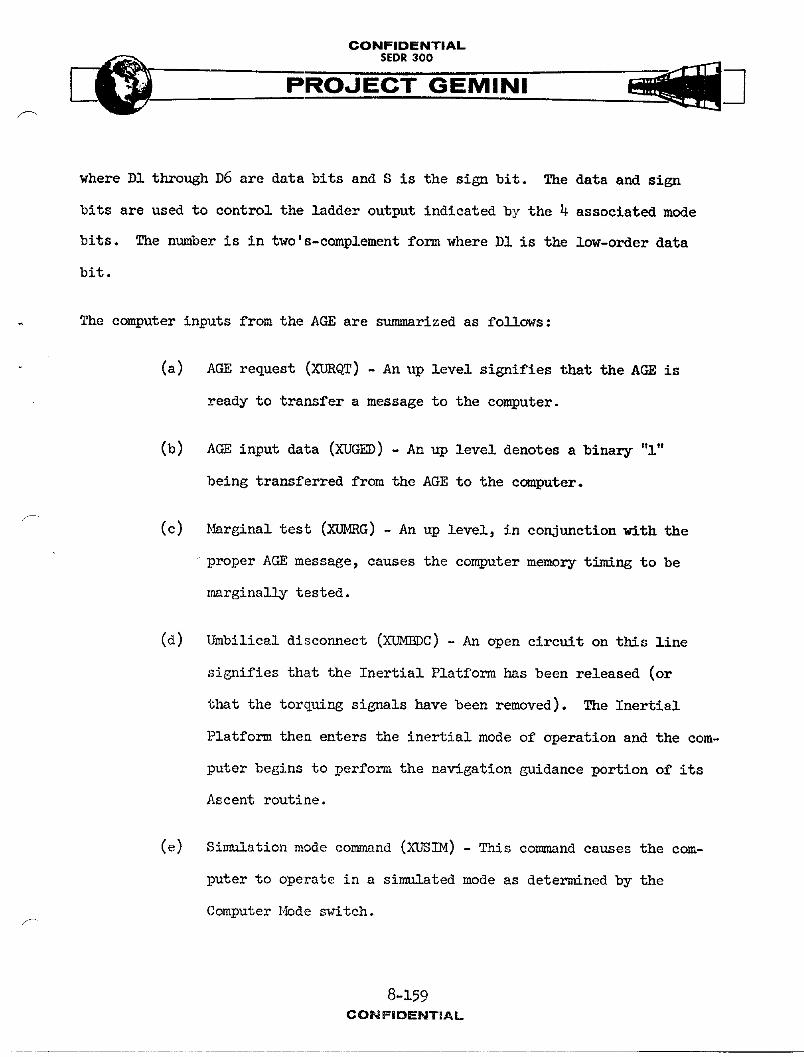
CONFIDENTIAL
_. $EDR 300
PROJECT GEMINI
where DI through D6 are data bits and S is the sign bit. The data and sign
bits are used to control the ladder output indicated by the 4 associated mode
bits. The number is in two's-complement form where D1 is the low-order data
bit.
The computer inputs from the AGE are summarized as follows:
(a) AGE request (XURQT) - An up level signifies that the AGE is
ready to transfer a message to the computer.
(b) AGE input data (XUGED) - An up level denotes a binary "l"
being transferred from the AGE to the computer.
(c) _rginal test (XUMRG) - An up level, in conjunctionwith the
proper AGE message, causes the computer memory t_m_ng to be
_marginally tested.
(d) Umbilical disconnect (XUMBDC) - An open circuit on this line
signifies that the Inertial Platform has been released (or
that the torquing signals have been removed). The Inertial
Platform then enters the inertial mode of operation and the com-
puter begins to perform the navigation guidance portion of its
Ascent routine.
(e) Simulation mode command (XUSIM) - This conmnandcauses the com-
puter to operate in a simulated mode as determined bythe
Computer Mode s_ritch.
8-159
CONFIDENTIAL
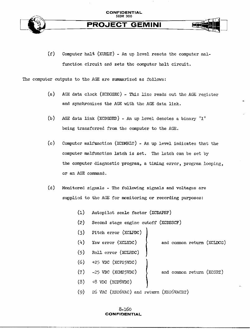
CONFIDENTIAL
PROJECT GEMINI,\
(f) Computer halt (XURLT) - An up level resets the computer mal-
function circuit and sets the computer halt circuit.
The computer outputs to the AGE are summarized as follows:
(a) AGE data clock (XCDGSEC) - This line reads out the AGE register
and synchronizes the AGE with the AGE data link.
(b) AGE data link (XCDGSED) - An up level denotes a binary "l"
being transferred from the computer to the AGE.
(c) Computer malfunction (XCDMALT) - An up level indicates that the
computer malfunction latch is set. The latch can be set by
the computer diagnostic program, a timing error, program looping,
or an AGE command.
(d) Monitored signals - The following signals and voltages are
supplied to the AGE for monitoring or recording purposes:
(i) Autopilot scale factor (XCDAPSF)
(2) Second stage engine cutoff (XCDSSCF)
(3) Pitch error (XCLPDC)
(4) Yaw error (XCLYDC) and commonreturn (XCLDCG)
(5) Roll error (XCLRDC)
(6) +25 VDC (XCP25VDC)
(7) -25 VDC (XCM25VDC) and commonreturn (XCSRT)
(8) +8wc (xcPSWC)
(9) 26 VAC (XS26VAC) and return (XS26VACRT)
8-160CONFIDENTIAL
CONFIDENTIAL
PROJECT GEMINI
(lO) +28 VDC filtered (XSP28VDC) and return (XSP28VDCRT)
(ll) +28 VDC unfiltered (XSP28UNF)
(12) +27.2 VDC (XSP27VDC)
(13) -27.2 VDC return (XSM27VDCRT)
+2oVDC(XS OV )
(15) +9.3wc (xsPgvDc)
(16) Power loss sensing (XQBND)
(17) Abort transfer (XHABT)
(18) Fade-in discrete (XHSFi)
MANUAL DATA INSERTION UNIT
SYSTEM DESCRIPTION
Purpose
The Manual Data Insertion Unit (_DIU) physically consists of the _nual Data
Keyboard (MDK) (Figure 8-41) and the _nual Data Readout (_DR) (Figure 8-42)
respectively. The MDIU enables the pilot to insert data into, and read
data from, the computer memoir.
Performance
Data Insertion: Before data is set up for insertion into the computer, s]l
existing data is cleared from the MDIU by pressing the CLEAR push-button switch
on the MDR. Then the Data Insert push-button switches on the MDK are used to
set up a 7-digit decimal number. The first two digits from the left specify
the address of the computer memory location in which the data is to be stored,
and the last five digits specify the data itself. As the data is set up, it
8-161CONFIDENTIAL

CONFIDENTIAL
PROJECT GEMINI
i
FLEGEND
I_M NOME NCLA'IURE
O DATA INSERT PUSH-BUTTON SWITCHES
Q CONNECTOR JI
O IDENTIFICATION PLA1E
EM2-8-,43
Figure 8-41 Manual Data Keyboard
8-162
CONFIDENTIAL
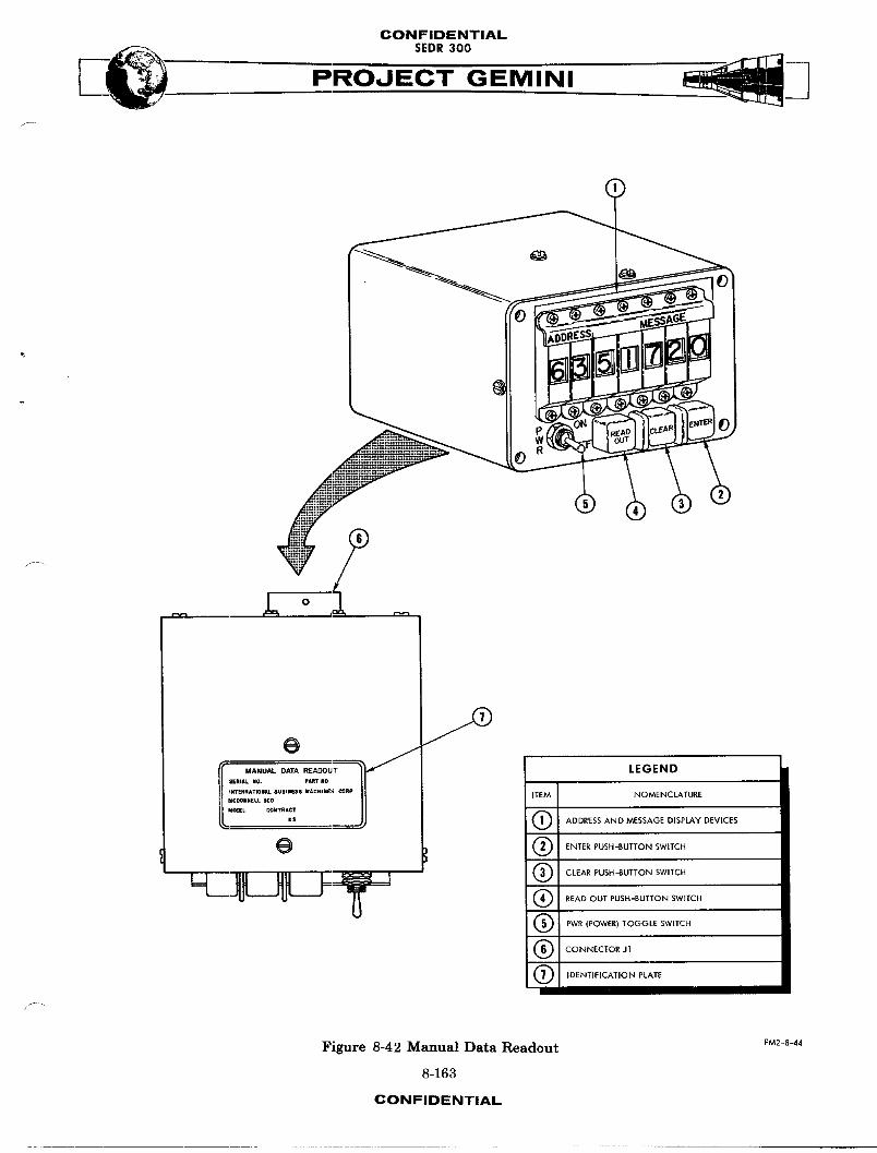
CONFIDENTIAL
PROJECT GEMINI
/
r-y-i
II I_ANU_-oA'rA_AOOUT _ LEGEND
SERIALNO. pARTN0
_F_NATm_L Busies uAcm_s c_np ITEM NOMENCLATURENCI_NNELL_0Ur_EL COleTRACT
US (_ ADDRESS AN D MESSAGE DISPLAY DEVICES
G Q ENTER PUSH -BUTTON SWITCH
Q CLEAR PUSH-BUTTON SWITCH
_ _--_ J=:_ o REA0GOT_OSH_OFTONSW,TCHQ PWR (POWER) TOGGLE SWITCH
(_ CONNECTOR J1
Q IDENTIFICATION PLATE
f"
Figure 8-42 Manual Data Readout F_-S-_
8-163
CONFIDENTIAL
CONFIDENTIAL
4, PROJECT GEMINI
is automatically supplied to the computer accumulator. A digit-by-digit veri-
fication of the address and data is made by means of the ADDRESS and MESSAGE
display devices on the MDR. After verification, the ENTER push-button switch
on the MDR is pressed to store the data in the selected memory location.
Data Readout
Before data is read from the computer, all existing data is cleared from the
MDIU by pressing the CT._.ARpush-buttton switch. Then the Data Insert push-
button switches are used to set up a 2-digit decimal number. The two digits
specify the address of the computer memory location from which data is to be
read. A digit-by-digit verification of the address is made by means of the
ADDRESS display devices. After verification, the READ OUT push-button switch
on the MDR is pressed and the data is read from the selected memory location
and displayed by the MESSAGE display devices.
MDK Physical Description
The MDK is 3.38 inches high, 3.38 inches wide, and 5.51 inches deep. It
weighs 1.36 pounds. External views of the MDK are shown on Figure 8-41.
The major external characteristics are mrmmarized in the accompanying legend.
MDR Physical Description
The MDR is 3.26 inches high, 5.01 inches wide, and 6.41 inches deep. It
weighs 3.15 pounds. External views of the MDR are shown on Figure 8-42.
The major external characteristics are sn_narized in the accompanying legend.
8-164CON FIDENTIAL
CONFIDENTIAL
SEDR300
PROJE'C'T'-G EMI NI
Controls and Indicators
The controls and indicators located on the MDK and MDR are _111mtrated on
Figure 8-43. The accompanying legend identifies the controls and indicators,
and describes their purposes.
SYST_4 OPERATION
Power
The MDIU receives all of the power required for its operation from the computer.
This power consists of the following regulated DC voltages:
(a) +25 VDC
I and common return
(b) -25wc )
(c) +8 VDC and return
This power is available at the MDIU whenever the computer is turned on. I_wever,
it is not actually applied to the MDIU circuits until the POWER switch on the
MDR is turned on. When power is turned on at the MDR, the regulated DO voltages
are filtered by a capacitor network and supplied to the MDK and MDR circuits.
MDK Data Flow (Figure 8-44)
The MDK has ten Data Insert pzish-button switches. These switches are used
to select the address of a computer memory location in which data is to be
stored or from which data is to be read. For storing data, the push-button
switches are also used to set up the actual data to be stored. Since the
push-button switches are numbered decimally, the insert button encoder is used
w- to convert their outputs to binary coded dec__mnl values that can be uaed by the
computer. These values, called the insert data signals, are supplied to the
8-165
CONFIDENTIAL
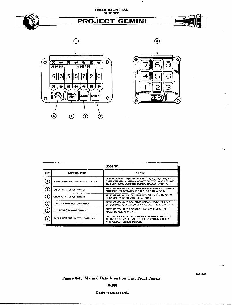
CONFIDENTIAL
PROJECT GEMINI
LEGEND
ITEM NOMENCLATURE PURPOSE
O DISPLAy ADDRESS AND MESSAGE SENT TO COMPUTER DURINGADDRESS AND MESSAGE DISPLAY DEVICES ENTER OPERATION; DISPLAY ADDRESS SENT TOt AND MESSAGE
RECEIVED PROM, COMPUTER DURING REAOOUT OPERATION.
Q PROVIDES MEANS FOR CAUSING MESSAGE SENT TO COMPUTERENTER PUSH-BUTTON SWITCH
DURING ENTER OPERATION TO BE STORED IN MEMORY,
(_ PROVIDES MEANS FOR CAUSING ADDRESS ANO MESSAGE SETCLEAR PUSH-SUTTON SWITCH
UP BY MDK TO BE CLEARED OR CANCELED.
Q PROVIDES MEANS FOR CAUSING MESSAGE TO BE READ OUTREAD OUT PUSH-RUTI"ON SWITCH OF COMPUTER AND DISPLAYED BY MESSAGE DISPLAY DEVICES.
Q PWR PROVIDES MEANS FOR CONTROLLING APPLICATION OF(POWER) TOGGLE SWITCH
POWER TO MDK AND MDE.
(_ PROVIDE MEANS FOR CAUSING ADDRESS AND MESSAGE TODATA INSERT PUSH-BUT[ON SWITCHES BE SENT TO COMPUTER AND TO BE DISPLAYED BY ADDRESS
AND MESSAGE DISPLAY DEVICES.
FM2-8-45
Figure 8-43 Manual Data Insertion Unit Front Panels
8-166
CONFIDENTIAL
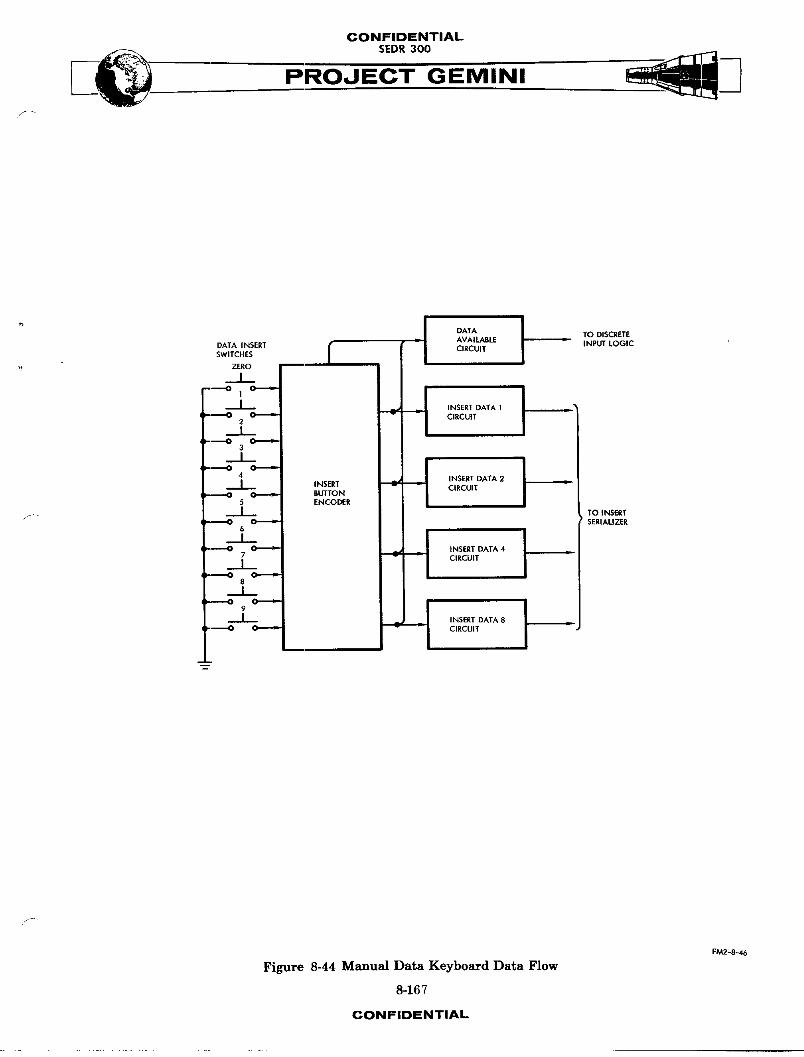
CONFIDENTIALSEDR300
DATA TO DISCRETEAVAILABLE INPUT LOGIC
DATA INSERT CIRCUITSWITCHES
. ZERO
IO ¢ a j
,; __ 'NSORTOATA'I' ': _ 2 C a _ CIRCUIT
3
I
INSERT DATA 2 •J INSERT
: 3 C _ BUTTON
ENCODER TO INSERT/_ ; _ C _ SERIALIZER
6
_I 7 C _ "I 0 INSERT DATA 4
CIRCUIT3 C
8
I
I INSERT DATA 8 •O C -_ _ CIRCUIT •
f
FM2--8-46
Figure 8-44 Manual Data Keyboard Data Flow
8-167
CONFIDENTIAL
J
CONFIDENTIAL
PROJECT GEMINI
insert serializer in the computer. The insert button encoder also develops the
data available signalwhich is supplied to the discrete input logic of the
computer.
MDR Data Flow (Fi6nlre 8-45
The MDR has seven digital display devices and three commsnd push-button switches.
The display devices are used to display the address set up by the Data Insert
push-button switches on the MDK, and to display either the data set up by the
Data Insert push-button s_tches or the data read from a computer memory loca-
tion. The com,_nd push-button switches, called ENTER_ READ OUT, and C_AR,
are used to determine whether data is entered into or read out of the computer,
or whether the data that has been set up is to be cleared (or canceled).
These push-button switches all supply inputs to the discrete input logic of the
computer. Since the display devices provide a decimal display, the binary
coded dee_A1 values received from the computer must be decoded before they
can be displayed. These values from the computer are supplied to three device
select control circuits and three insert data circuits. Another signal from
the computer is supplied to the display device drive control circuit. A com-
bination of outputs from the device select control circuits is used in conjunc-
tion _th the outputs of the display device drive control circuit to select
a particular display device. This selection is accomplished by means of the
device selector. A combination of outputs from the insert data circuits is used
in conjunction with the outputs of the display device drive control circuit
to select a particular number on the selected display device. This selection
8-168
CONFIDENTIAL
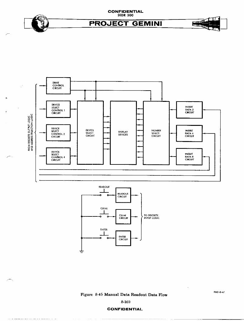
CONFIDENTIAL
___ SEDR 300
PROJECT GEMINI
DRIVECONTROLCIRCUIT
DEVICESELECT INSERT
--.-e,- CONTROL1 = J DATA2CIRCUIT CIRCUIT
Uu_ -_(30O__ZSO
_ DEVICE -__u:3 _ DEVICE J NUMBER INSERTO _ _ SELECT DISPLAY SELECT DATA 4 •
CONTROL 2 = SELECT -- DEVICESw_- __ CIRCUIT CIRCUIT z CIRCUIT CIRCUIT
DEVICESELECT INSERT
_ CONTROL 4 = = DATA 8CIRCUIT CIRCUIT
READOUT
-0 C _ _
CLEAR
I ['_ TOD,SCRETE0 _ =J C.RCU.J _ ,N._"LO_.C
p
ENTER
O C _ I CIRCUIT I
FM2-8-47
Figure, 8-45 Manual Data Readout Data Flow
8-169
CONFIDENTIAL
CONFIDENTIAL
PROJECT GEMINI\
is accomplished by means of the number selector. Thus, through the combined
operations of the device selector and the number selector, the binary coded
decimal values received from the computer are decoded and an equivalent decimal
display is presented on the display devices.
Manual Data Subroutine
The Manual Data subroutine, which determines when data is transferred between
the MDIU and the computer, is described under the Operational Pro6ram heading
in the DIGITAL CO_UTER SYST_4 OPERATION part of this section.
Interfaces
The _IU interfaces, all of which are made with the computer, are described
under the Interfaces heading in the DIGITAL COMPUTER SYSTEM OPERATION part ....
of this section.
INCREMENTAL VELOCITY INDICATOR
SYST2_ DESCRIPTION
Purpose
The Incremental Velocity Indicator (IVI) (Figure 8-46) provides visual indica-
tions of incremental velocity for the longitudinal (forward-aft), lateral
(left-right), and vertical (up-down) axes of the spacecraft. These indicated
incremental velocities represent the amount and direction of additional velocity
or thrust necessary to achieve correct orbit, and t_Ja are added to the existing
spacecraft velocities by means of the maneuver thrusters.
8-170
CONFIDENTIAL
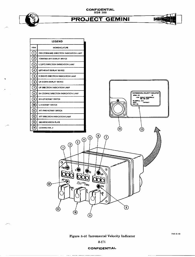
CONFIDENTIALSEDR 300
/
LEGEND
I1_M ! NOME NCLAIURE
FWD (FORWARD) DIREC11ON INDICATION LAMP
Q FORWARD-AFT DISPLAY DEVICE
O L (LEFI_ DIRECTION INDICATION LAMp
(_ LEFT-RIGHT DISPLAY DEVICE
Q R (RIGHT} DIRECTION INDICATION LAMP
Q UP_C_VN DISPLAY DEVICE I
(_ UP DIRECtiON INDICATION LAMP
® ,._,_,ow_,.,REc..o_,.,.,CA..o.,_. [l""_-'1'J__'_.'2_'_,,-,,,,_,, ,_,,,,_
(_ L-R ROTARY SWITCH O O _t_o. CemS_CT
(_ AFT-FWD ROTARY SWITO'I
(_ AFT DIRECTION INDICATION LAMp . I
(_ IDENTIFIOk11ON PLATE
F_ -8-48
Figure 8-46 Incremental Velocity Indicator
8-171
CONFIDENTIAL
CONFIDENTIALSEDR300
Performance
A three-digit decimal display device and two direction indication lamps are
used to display incremental velocity for each of the three spacecraft axes.
Both the l_mps and the display devices can be set up either manually by rotary
switches on the IVI or automatically by inputs from the computer. Then, as
the maneuver thrusters correct the spacecraft velocities, pulses are received
from the computer which drive the display devices toward zero. If a display
device is driven beyond zero, indicating an overcorrection of the spacecraft
velocity for the respective axis, the opposite direction indication lamp lights
and the display device indication increases in magnitude to show a velocity
error in the opposite direction.
Physical Description
The IVI is 3.25 inches high, 5.05 inches wide, and 5.89 inches deep. It
weighs 3.25 pounds. External views of the IVI are shown on Figure 8-46. The
major external characteristics are summarized in the accompanying legend.
Controls and Indicators
The controls and indicators located on the M are illustrated on Figure 8-47.
The accompanying legend identifies the controls and indicators, and describes
their purposes.
SYSTem4 OPERATION
Power
The power required for operation of the IVI is supplied by the IGS Power Supply
whenever the computer is turned on. The power inputs are as follows:
8-172CONFIDENTIAL
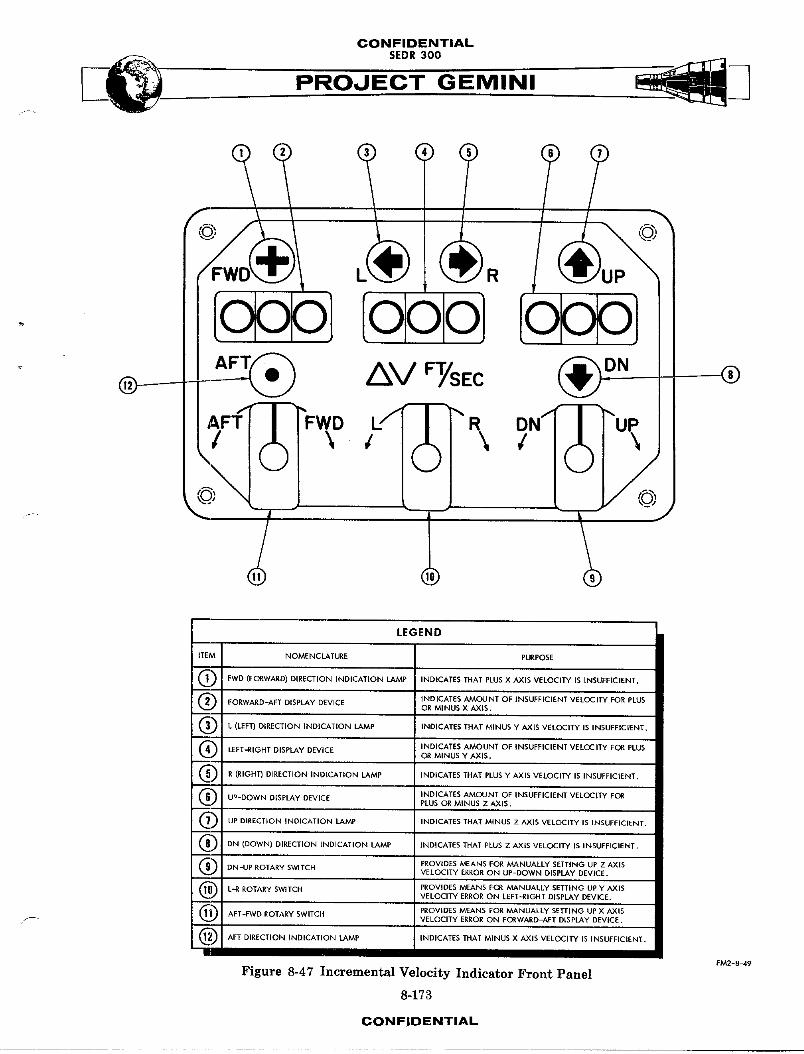
CONFIDENTIALSEDR300
R
FTSEC DN
Lf R DN/_-J I
LEGEND
ITEM NOMENCLATURE PURPOSE
O FWD (FORWARD) DIRECTION iNDICATION LAMP INDICATES THAT PLUS X AXIS VELOCITY IS INSUFFICIENT.
Q FORWARD-AFT DISPLAY DEVICE INDICATES AMOUNT OF INSUFFICIENT VELOCITY FOR PLUSOR MINUS X AXIS.
Q L (LEFT) DIRECTION INDICATION LAMP INDICATES THAT MINUS Y AXiS VELOCITY IS INSUFFICIENT.
Q LEFT-RIGHT DISPLAY DEVICE INDICATES AMOUNT OF INSUFFICIENT VELOCITY FOR PLUSOR MINUS Y AXIS.
O R (RIGHT) DIRECTION INDICATION LAMP INDICATES THAT PLUSY AXiS VELOCITY IS INSUFFICIENT.
O Uu-DOWN DISPLAY DEVICE iNDICATES AMOUNT OF INSUFFICIENT VELOCI'IY FC_RPLUS OR MINUS Z AXIS.
Q UP DIRECTION IND[CATION LAMP INDICATES THAT MINUS Z AXIS VELOCITY IS INSUFFICIENT.
(_ DN (DOWN) DIRECTION INDICATION LAMP INDICATES THAT PLUS Z AXiS VELOCITY IS INSUFFICIENT.
(_ DN-UP ROTARY SWITCH PROVIDES MEANS FOR MANUALLY SETTING UP Z AXISVELOCITY ERROR ON UP-DOWN DISPLAY DEVICE.
(_) L'-R ROTARY SWITCH PROVIDES MEANS FOR MANUALLY SETTING UP Y AXISVELOCITY ERROR ON LEFT'-RIC4-1TDISPLAY DEVICE.
(_ AFT-FWD ROTARY SWITCH PROVIDES MEANS FOR MANUALLY SETTING UP X AXISVELOCITY ERROR ON FORWARD-AFT DISPLAY DEVICE.
Q AFT DIRECTION INDICATION LAMP INDICATES THAT MINUS X AXIS VELOCITY IS INSUFFICIENT,
FM2--8-49
Figure 8-47 Incremental Velocity Indicator Front Panel
8-173
CONFIDENTIAL
CONFIDENTIALSEDR300
(a) +27.2 VDC and return
(b) +5 VDC and return
During the first 30 seconds (or less) follo_-lngthe application of power, the
incremental velocity counters on the IVI are automatically driven to zero.
Thereafter, the IVI is capable of normal operation.
Basic Operation
The IVI includes three identical channels, each of which accepts velocity error
pulses for one of the spacecraft axes and processes them for use by a decimal
display device and its two associated direction indication lamps. The velocity
error pulses are either received from the computer or generated within the
IVI, as determined by the position of the rotary switch associated with each
channel. With the spring-loaded switches in their neutral center positions,
the IVI processes only the pulses received from the computer. However, rotation
of the switches in either direction removes the pulses received from the com-
puter and replaces them with pulses generated by an internal variable oscillator.
These pulses are generated at a rate of one pulse per second for every l3.5
degrees of rotation until the rate reaches 10 pulses per second. Rotation
of the switches beyond the lO pulse per second position removes the pulses
generated by the variable oscillator and replaces them with pulses generated
by an internal fixed oscillator. These pulses are generated at a rate of 50
pulses per second. Rotation of the switches beyond the 50 pulse per second
position is limited by mechanical stops.
8-174CONFIDENTIAL
CONFIDENTIALSEDR300
The first pulse received on any channel, from either the computer or one of the
osci1!ators, causes the appropriate display device to display a count of one.
Simultaneously, this same pulse causes one of the two associated direction
indication lamps to light. If the pulse was received on a positive input line,
a forward, right, or down direction is indicated, depending on which channel
(X, Y, or Z) received the pulse; and if the pulse was received on a negative
input line, an aft, left, or up direction is indicated, depending on which
channel received the pnlae. Each additional pulse either increases or decreases
the count depending on the relationship between the sign of the existing value
on the counters and the sign of the added pulse as determined by the line on
which it is received. A pulse having the same sign as the existing error increases
F_ the count; conversely, a pulse having the opposite sign of the existing error
decreases the count. A series of pulses having the opposite sign indicates
a corrective thrusting and eventually reduces the indicated error to zero.
An overcorrection, causing still more pulses, causes the count to increase again
but with the opposite direction indication lamp lit.
Zero Indication
As shown on Figure 8-48, three series-connected switches are operated by the
Forward-Aft display device. (The same thing is true for the Y and Z channels;
however, since the three channels are identical, only the X channel is shown.)
When the display device indicates O00, all three switches are closed. A
-27.2 VDC signal is then applied to the X zero indication driver which develops
the X zero indication signal that is supplied to the computer. This signal
indicates that the respective counter is at zero.
8-175CONFIDENTIAL
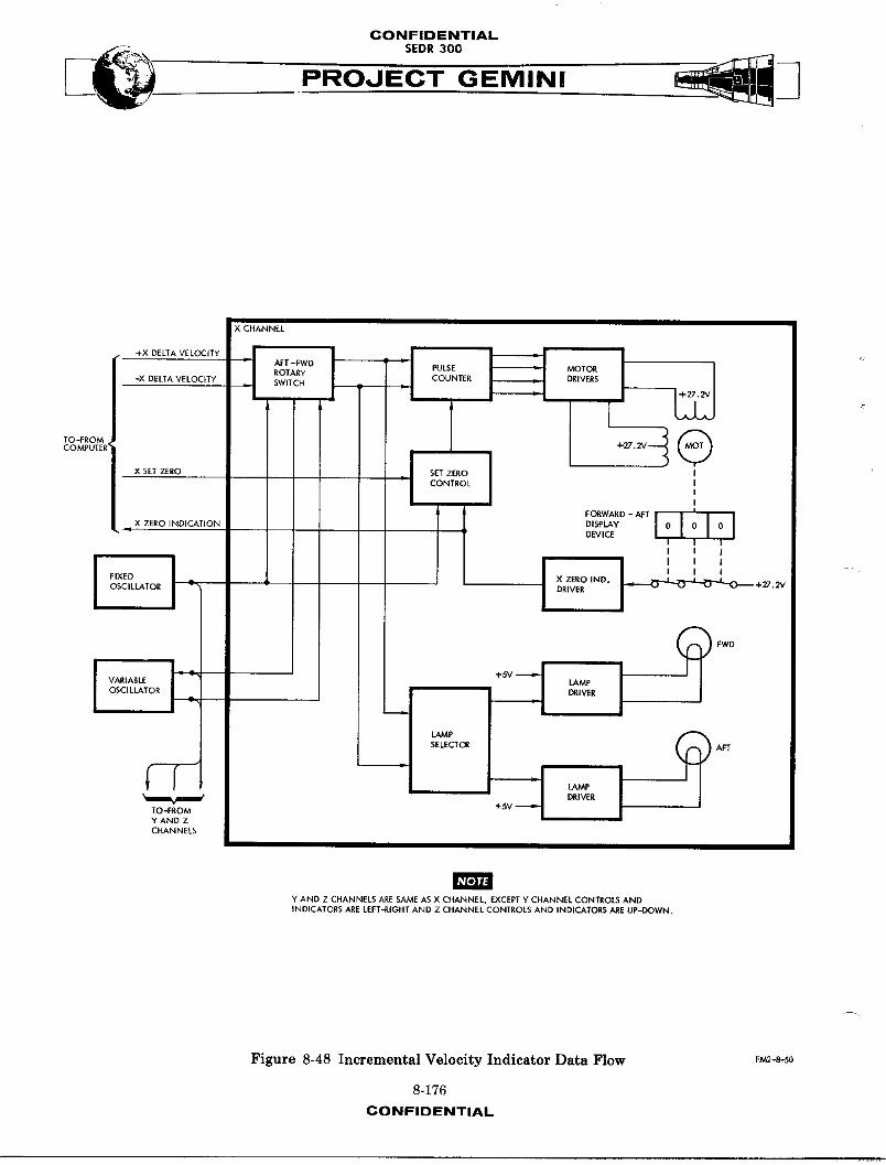
CONFIDENTIAL
PRO,JECT GEMINI
X CHANNEL
ROTARY COUNTER DRIVERS-X DELTA VELOCITY SWITCH
X SET ZERO "- SET ZERO J I
CONTROL J II
,, ZERO,NDICAT,ON 0'S' YI010101
DEWI_ II
FIXED X ZERO IND. _.-...L _ A ÷_.2 VOSCILLATOR DRIVER
OSCILLATOR DRIVER
SELECTOR APT
i LAMp"q _ DRIVER
TO -FROM +5V -_ IY AND ZCHANNELS
NOTE
Y AND Z CHANNELS ARE SAME AS X CHANNEL, EXCEPT Y CHANNEL CONTROLS ANDINDICATORS ARE LEFT-RIGHT AND Z CHANNEL CONTROLS AND INDICATORS ARE UP-DOWN.
Figure 8-48 Incremental Velocity Indicator Data Flow F_-S-50
8-176
CONFIDENTIAL
CONFIDENTIALSEDR 300
f/
Pulse Count
Velocity error pulses are applied to the lamp selector and the p,,1_ecounter
via the AFT-FWD rotary switch. If the switch is in the center position, these
pulses are received from the computer on the +X delta velocity line and the -X
delta velocity line. If the switch is not in the center position, the p,iS_es
are received from either the fixed oscillator or the variable oscillator. As
previously explained, the oscillator that is used depends on the exact position
of the switch. Regardless of the source of the p,_%qes,the 1_p selector and the
pulse counter operate the same. The lamp selector determines, by means of the
sign of the error, which lamp should be lit. Power is then supplied to the
selected lamp via the associated lamp driver. Meanwhile, the same pulses are
_- being processed by the pulse counter and supplied to the motor drivers. The
p,,l_ecounter and the motor drivers operate in a manner that causes the motor
to be driven 90 degrees for each pulse that is counted. The direction in which
the motor is driven is determined by the relationship between the sign of
the existing velocity error count and the sign of the added velocity error pulse.
The motor drives the display device so that it changes by a count of one for
each 90 degrees of motor rotation. Thus the display device maintains an up-to-
date count of the size of the velocity error for the associated axis (in this
case, the X axis), and the direction indication lamps maintain an up-to-date
indication of the direction of the error.
F"
8-177CONFIDENTIAL
CONFIDENTIAL
PROJECT GEMINI
Zero Comm_nd
The IVI counters can be individunS1y driven to zero by means of set zero signals
(X set zero, on Figure 8-48) supplied by the discrete output logic of the
computer. The set zero signal is supplied to the set zero control circuit
which gates the 50 pps output from the fixed oscillator into the pulse counter,
provided the display device counter is not already at zero. The pulses from
the fixed oscillator then drive the motor in the normal manner until the counter
is zeroed. The l_1]_es are applied in such a manner that the count always de-
creases, regardless of the initial value.
Interfaces
The IVI interfaces, which are made with the computer and the IGS Power Supply, -_
are described under the Interfaces heading in the DIGITAL COMPUTER SYSTF_M OPERA-
TION part of this section.
8-178CONFIDENTIAL
CONFIDENTIAL
HORIZON SENSOR SYSTEM
TABLE OF CONTENTS
TITLE PAGE
SYSTEM DESCRIPTION ....... 8-181
SENSOR HEAD ............ 8-181ELECTRONICS PACKAGE. ..... 8-183
SYSTEM OPERATION .......... 8-183INFRARED OPTICS .......... 8-186INFRARED DETECTION ..... 8-188SERVO LOOPS ............. 8-189HORIZON SENSOR POWER ..... 8-204
SYSTEMUNITS............. 8-206SENSOR HEAD .......... 8-206ELECTRONICS PACKAGE ...... 8-209
8-179
CONFIDENTIAL

CONFIDENTIAL --
PROJECT GEMINI
RIGHT SWITCH/CIRCUITBREAKERPANEL_
SEEDETAI
" SEEDETAILB
PACKAGES
'--SECONDARY HORIZON SENSORHEAD
-PRIMARy HORIZON SENSORHEAD
HORIZON SENSORFAIRING
FM2-8-50
Figure 8-49 Horizon Sensor System
8-180
CONFIDENTIAL

CONFIDENTIAL
PROJECT GEMINI
HORIZON SENSOR SYSTEM
SYSTEM DESCRIPTION
The Horizon Sensor System (Figure 8-49) consists of a sensor head, an elec-
tronics package and their associated controls and indicators. The system is
used to establish a spacecraft attitude reference to earth local vertical and gen-
erates error signals proportional to the difference between spacecraft attitude
and a horizontal attitude. Attitude error signals can be used to align either
the spacecraft or the inertial platform to earth local vertical. The system
has a null accuracy of O.1 degree and is capable of operating at altitudes of
50 to 900 nautical miles. When the system is operating in the 50 to 550
f nautical mile a,ltituderange, measurable spacecraft attitude error is _ 14
degrees. When spacecraft attitude errors are between 14 and 20 degrees, the
sensor output becomes non-llnear but the direction of its slope always corresponds
with the slope of the attitude error. When spacecraf% attitude errors exceed
20 degrees, the system may lose track. Two complete systems are installed on the
spacecraft. The second system is provided as a back-up in case of pl_mRry system
malfunction.
SKNSORHEAD
The sensor head (Figure 8-50) contains equipment required to scan, detect and
track the infrared gradient between earth and space, at the horizon. The
sensor heads are mounted on the left side of the spacecraft and canted 14 degrees
forward of the spacecraft pitch axis. Scanning is provided about the azimuth
axis by a yoke assembly and about the elevation axis by a Positor (mirror
positioning assembly). Infrared detection is provided by a bolometer and track-
ing by a servo loop which positions the Positor mirror.8-18].
CONFIDENTIAL
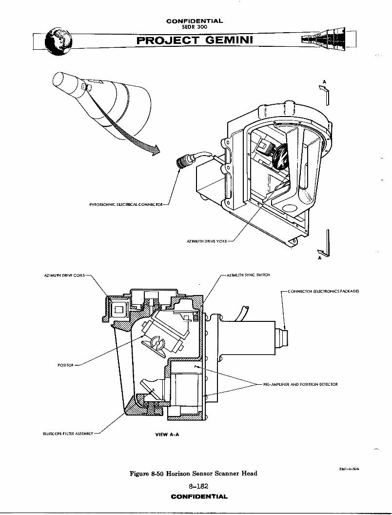
CONFIDENTIALSEDR300
PYROTECHNIC ELECTRICAL CONNECTO
AZIMUTH SWITCH
CONNECTOR (ELECTRONICS pACKAGE)
FOSITOR'
TELESCOPE FILTER ASSEMBLY VIEW A-A
FM1-8-50A
Figure 8-50 Horizon Sensor Scanner Head
8-182
CONFIDENTIAL
CONFIDENTIALSEDR300
ELECTRO_-ICSPACKAGE
The electronics package (Figure 8-51) contains the circuitry required to pro-
vide azimuth and elevation drive signals to the sensor head and attitude error
signals to spacecraft and platform control systems. Electrical signals from the
sensor head, representing infrared radiation levels and optical direction, are
used to generate elevation drive signals for the Positor. Signals are also
generated to constantly drive the azimuth yoke from limit to limit. Attitude
error signals are derived from the constantlY changing Positor position signal
when the system is tracking.
SYSTEM OPERATION
The primary Horizon Sensor System is energized during pre-launch by pilotf
initiation of the SCAN HTR and SCANNER PRI-OFF-SEC switches. Tmmediately after
staging the pilot presses the JETT FAIR switch, exposing the sensor heads to
infrared radiation. Initial acquisition time (the time required for the sensor
to acquire and lock-on the horizon) is approximately 120 seconds; reacquisition
time is approximately i0 seconds. The system can be used any time between
staging and retro-section separation. At retro-section separation plus 80
m_!1_seconds the sensor heads are automatically jettisoned, rendering the system
inoperative.
Operation of the Horizon Sensor System depends on receiving, detecting and
tracking the infrared radiation gradient between earth and space, at the
horizon. To accomplish the above, the system employs infrared optics, infrared
detection and three closely related servo loops. A functional block diagram
of the Horizon Sensor System is provided in Figure 8-52.
8-183CONFIDENTIAl.
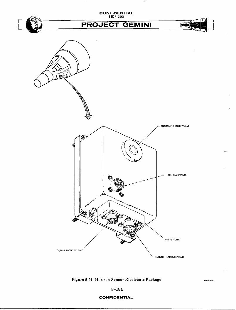
CONFIDENTIAL
L PROJECT GEMINI
/ _AUTOMATIC RELIEFVALVE
TEST RECEPTACLE
Figure 8-51 Horizon Sensor Electronic Package FM¢-_A
8-18h
CONFIDENTIAL

f .

CONFIDENTIAL
SEOIt300
PROJECT GEMINI
INFRARED OPTICS
Infrared optics (Figure 8-53) consists of a Positor, a telescope-filter assembly
and an azimuth drive yoke. AII of these components are located &n the sensor
head. The Positor has a movable mirror which is used to position the system
field of view about the horizon. Radiation is reflected by the Positor mirror
into the telescope-filter assembly. A fixed mirror, in the telescope-filter
ass_nbly, directs infrared radiation into the telescope. The telescope-filter
assembly contains a germanium meniscus objective lens, an infrared filter and
a germanium-_mmersed thermistor bolometer. The objective lens is used to
direct all the infrared radiation, reflected by the mirrors, on the germanium
_mmersion lens of the bolometer. The infrared filter is used to eliminate
radiation of undesired frequencies. The filter has a band pass of 8 to 22
microns (80,000 to 220,000 angstroms). The germanium immersion lens focuses
the infrared radiation on an immersed thermistor.
The Horizon Sensor field of vi_ is deflected through 160 degrees (+ 80) in
azimuth and 70 degrees (12 up and 58 down) in elevation by rotating the Positor
mirror. The Positor is rotated in azimuth by a drive yoke. Rotation is about
an axis which runs through the center of the infrared ray bundle on the surface
of the Positor mirror. The yoke is driven at a one cycle per second rate by
circuitry in the electronics package. The center of the az_,_th scan is 14
degrees forward of the spacecraft pitch axis. This is due to the mounting of
the scanner heads. Elevation deflection is provided by the Posltor which
tilts the Positor mirror as required to search for or track the horizon. The
8-1_6CONFIDENTIAL
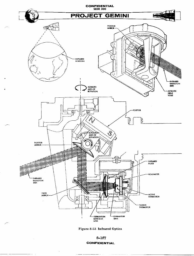
CONFIDENTIAL
r-- '::_'_ -
I PROJECT GEMINI
• '%.. • •
/ \
/ \ \/ \
/ \
/ .'1 -.-.,.',,,
",4"X_,,, @.,_=F--("""" ( ] i .o.zoN\,_x\, ,,. / j
. -.\_-..-_;/ ,_ RADIATION
AZIMLrfH (REF)AXIS OF
I ROTATION , ',t"_ DRIVEYOKE
1 ! ' '
AXIS OF 'ROTATION
POSITOR
MIRROR i
FILTER
,LOMETERINFRARED
RADIATION(REF) t
II
FIXED
THERMISTOR
iTHERMISTOR
I GERMANIUM NIUMMENISCUS LENSLENS
Figure 8-53 Infrared Optics
8-Z87CONFIDENTIAL
CONFIDEENTIAL
rate at which the Positor tilts the mirror is a function of the mode of opera-
tion (track or search). In search mode,the Positor mirror moves at a two
cps search rate plus a 30 cps dither rate. In track mode,the Positor mirror
moves at a BO cps dither rate, plus, if there is any attitude error, a one or
two cps track rate. The one or two cps track rate depends on the direction of
spacecraft attitude error.
INFRARED DETECTION
Infrared radiation is detected by the germanium-immersed thermistor bolometer.
The bolometer contains two thermistors (temperature sensitive resistors) which
are part of a bridge circuit. One of the thermistors (active) is exposed to
infrared radiation from the horizon. The second thermistor (passive) is located
very near the first thermistor but it is separated from infrared radiation.
Radiation from the horizon is sensed by the active thermistor which changes
resistance and unbalances the bridge circuit. The unbalanced bridge produces
an output voltage which is proportional to the intensity of the infrared radiation.
If only one thermistor were used, the bridge would also sense temperature changes
caused by conduction or convection; to prevent this, a passive (temperature
reference) thermistor is used.
The passive thermistor changes resistance the same amount as the active ther-
mistor, for a given ambient temperature change, keeping the bridge balanced.
The passive thermistor is not exposed to infrared radiation and allows the
bridge to become unbalanced when the active thermistor is struck by radiation
from the horizon.
8-].88CONiFIDKNTIAL.

CONFIDENTIAL
SEDR300PROJECT GEMINI
f-,/
SERVO LOOPS
The three servo loops used by the Horizon Sensor System are: the track loop,
the azimuth drive loop and the signal processing loop. Some of the circuitry
is used by more than one servo loop and provides synchronization.
Track Loopw
The track loop (Figure 8-54) is used to locate and track the earth horizon
with respect to the elevation axis. Two modes of operation (search and track)
are used in the track loop. The search mode is selected automatically when
the system is first energized and used until the horizon is located. After
the horizon is located and the signal built up to the required level, the
track mode is automatically selected.
Search Mode
The search mode is automatically selected by the system any time the horizon
is not in the field of view. The purpose of the search mode is to move the
system line of sight through its elevation scan range until the horizon is
located. (The system line of sight is moved by changing the angle of the
positor mirror. ) Nhen the system is initially energized, the Positor position
signal is used to turn on a search generator. The generator produces a twTo
cps AC search voltage which is applied to a summqng junction in the Positor
drive amplifier. A second signal (30 cps dither) is also applied to the
s11mm_ngjunction. (The dither signal is present any time the system is energized. )
The search and dither voltages are s_mmed and amplified to create a Positor
drive signal. This drive signal is applied to the drive coils of the Positor
fcausing it to tilt the Positor mirror. The dither portion of the signel
causes the mirror to oscillate about its elevation axis at a 30 cps rate and
8-189CONIFIDISNTIAL
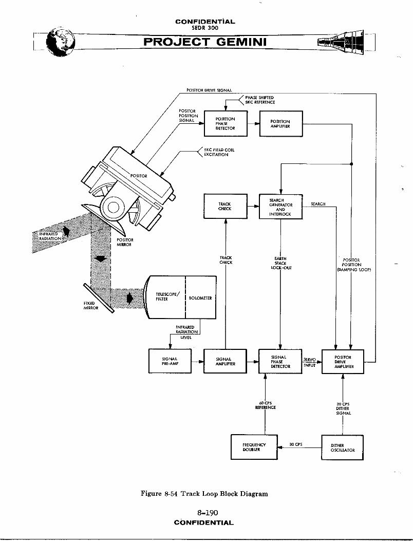
CONFIDENTIAL
J V PROJECT GEMINI
POSITORDRIVESIGNAL
FOS,TOR_--_ _K'_R_EE_'E%_
POSITION J_
SIGNAL POSITION POSITIONPHASEDETECTOR AMPLIFIER
:OILEXCITATION
H SEARCH
TRACK GENERATOR SEARCHCHECK AND
INTERLOCK
POSITORMIRROR
TRACK EAI_H POSITORCHECK SPACE POSITION --
LOCK-OUT _AMPING LOOP)
TELESCOPE/FILTER BOLOMETER
FIXEDMIRROR
INFRARED
LEVEL
PI_,._MP ,_'iP LIFIEl PHASE DRIVEDETECTOR AMPLIFIER
T60CPS 30CPS
REFERENCE DITHER
SlibtAL
DOUBLER OSCILLATOR
Figure 8-54 Track Loop Block Diagram
8-190
CONFIDENTIAL
GONFIDENTIAL
[_ SEDR300
PROJECT GEMINI
through an angle which represents approximately four degrees change in the
line of sight. The search portion of the signal will drive the Positor mirror
up to an angle which represents a line of sight 12 degrees above the spacecraft
azimuth plane. During the up scan (earth to space) a lock-out signal is
applied to the servo loop to prevent the system from locking on to false hori-
zon indications. When the positive limit of the search voltage (12 degrees up)
is reached_ the voltage changes phase and the system begins to scan from 12
degrees up to 58 degrees down. During the down scan (space to earth), the
lock-out signal is not used and the system is free to select track mode if the
horizon comes within the field of view.
The bolometer output (indication of infrared radiation) is used to determine
when the horizon comes withinview and to initiate the track mode of operation.
As the system line of sight crosses the horizon (from space to earth), a sharp
increase in infrared radiation is detected by the bolometer. The bolometer
bridge output now produces a 30 cps AC signal. (The 30 cps is caused bythe
dither signal driving the line of sight back and forth across the horizon.)
The bolometer bridge output is amplified and applied to the track checkcir-
cult. When the 30 cps signal reaches the track check circuit_it causes a
tracking relay to be energized indicating that the horizon is in the field of
view. Contacts of the relay apply a bias to the search generator, turning it
off and removing the search voltage from the Positor drive signal. This places
the system in the track mode of operation.
S"
8-191CONFIDfNTIAL

CONFIDENTIAL
PROJECT GEMINI
Track Mode
The bolometer output signal is used to determine the direction of the horizon
from the center of the system line of sight. A Positor drive voltage of the
proper phase is then generated to move the system line of sight until the
horizon is centered in the field of view. The bolometer output signal is
phase detected with respect to a 60 cps reference signal. The 60 cps signal
is obtained by doubling the frequency output of the dither oscillator. Since
both signals (30 cps dither and 60 cps reference) come from the same source,
the phase relationship should be a constant. However, when the horizon is not
in the center of the field of view, the bolometer output is not s_etrical.
The time required for one complete cycle is the same as for dither but the
zero crossover is not equally spaced, in time, from the beginning and end
of each cycle. The direction the zero crossover is shifted from center depends
on whether the horizon is above or below the center of the field of view. The
phase detector determines the direction of shift (if any) and produces DC pulses
of the appropriate polarity. The output of the signal phase detector is applied
to the Positor drive amplifier where it is m,-_ed with the dither signal. The
composite signal is then amplified and used to drive the Positor mirror in the
direction required to place the horizon in the center of the field of view.
A pickup coil, wound on the permanent magnet portion of the Positor drive
mechanism, produces an output signal which is proportional (in phase and ampli-
tude) to the position of the Positor mirror. This Positor position signal is
phase detected to determine the actual position of the mirror. The detector
output is then amplified and used for two purposes in the track loop: to activate
8-19"2CON FIOENTIAL

CONFIDENTIAL
SEDR300
PRNI
the search generator when the tracking relay is de-energized and as a rate
damping feedback to the Positor drive amplifier. (When the tracking relay is
energized, lt biases the search generator to cutoff.)
Azimuth Drive Loop
The azimuth drive loop (Figure 8-55) provides the drive voltage, overshoot
control and synchronization required to move the system line of sight through
a 160 degree scan angle at a one cps rate. The azimuth drive loop consists
of an azimuth overshoot detector, azimuth control circuit, azimuth multivibrator,
azimuth drive coils and an azimuth drive yoke.
Azimuth Overshoot Detectorf
The azimuth overshoot detector does not, as the name implies, detect the
azimuth scan overshoot. It instead detects when the azimuth drive yoke reaches
either end of its scan l_m_t. The detector is a magnetic pickup, located near
the azimuth drive yoke and excited by a 5 KC signal from the field current
generator. Two iron slugs, mounted on the azimuth drive yoke, pass very near
the magnetic pickup when the yoke reaches the scan limit. The slugs are posi-
tioned 160 degrees apart on the yoke to represent each end of the scan. When
one of the iron slugs passes near the magnetic pickup, it changes the inductance
and causes the 5 KC excitation signal to be modulated with a pulse. Since the
azimuth scan rate is one cps and the modulation occurs at each end of the scan,
the overshoot pulse occurs at a two pps rate. Output of the overshoot detector
is applied to the azimuth control circuit.
8-193CONFIDENTIAL
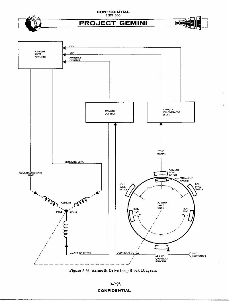
CONFIDENTIAL-- SEDR300
I PROJECT GEMINI
d CCW,q
AZ/MUTHDRIVE • CWAMPUFIER q
AMPLITUDE
d CONTROL
AZIMUTHAZIMUTH MULTIVIBRATORCONTROL (1 CPS)
SYNCSIGNAL
1
CLOCKWISE DRIVE J
AZIMUTH
COUNTERCLOCKWISE SYNCDRIVE $_VITCH
SYNC
¢ITCH
/ o/ :
/ o
/ t/ /* 5KC
/ AMPLITUDE SWITCH DVERSHOOT SIGNAL _ EXCITATION
/ / AZIMUTHOVERSHOOT
_. j DETECTOR __
Figure 8-55 Azimuth Drive Loop Block Diagram
8-19h
CONFIDENTIAL
CONFIDIENTIAL
SEDR300
Azimuth Control Circuit
The azimuth control circuit generates two types of azimuth control voltages
(coarse and fine) based on the azimuth overshoot signal. The az_..Ith over-
shoot detector output is rectified, filtered, peak detected and integrated to
develop a DC control voltage proportional to the Amplitude and width of the
" overshoot pulse. This control voltage serves two purposes: to provide con-
tinuous, fine control of the azi_!th drive pulse and, when the control voltage
reaches a high enough level (indicating a large overshoot), provide a coarse
(step) control of the reference voltage on the azi..xth drive coils. The fine
control is obtained by applying the control voltage, as a bias, to the azimuth
drive amplifier. The coarse control is obtained by energizing a relay, which
F_ switches the reference voltage on the azimuth drive coils when the control vol-
tage reaches a high enough level. The level at which the relay energizes is
determined by a zener diode which breaks down and biases a relay driver into
conduction. The relay driver then energizes a relay which switches the DC
voltage on the reference winding of the az__]th drive coils.
Azimuth Multivibrator
The azimuth multivibrator provides the direction control signal for the azimuth
drive. The multivibrator is synchronized by puS aes from the azimuth sync switch.
The sync switch is located next to the az_.-,th drive yoke and is closed each
time the yoke passes through the center of its 160 degree scan. The switch
produces a two pps output which is used to switch the state of the multivi-
brator. The multivibrator then produces a one cps square wave signal which is
8-195CONIFIIDWNTIAL

CONFIDENTIAL
i PROJECT GEMINI
synchronized with the motion of the azimuth drive yoke. The positive half of
the square wave controls the azimuth drive in one direction and the negative
half controls the drive in the other direction. Output of the multivibrator is
applied to the azimuth drive amplifier.
Azimuth Drive Amplifier
The azimuth drive amplifier adjusts the width of multivibrator output pulses
to control the azimuth drive yoke. The output pulse width, from the drive
amplifier, depends on the amount of control voltage (bias) provided by the
azimuth control circuit. When the amount of azimuth yoke overshoot is large,
the control voltage is high and the output pulse width is narrow. As the
amount of overshoot decreases, the control bias decreases and the output pulse
width increases. This provides a continuous, fine control over the drive pulse
and consequently the amount of azimuth drive yoke travel.
Azimuth Drive Coils
The az_,,ithdrive coils convert drive signals into a magnetic force. The
coils are mounted next to, and their magnetic force exerted on, the azimuth
drive yoke. The direction of magnetic force is determined by which drive coil
is energized.
Azimuth Drive Yoke
The azimuth drive yoke is a means of mechanicaS_y moving the system line of sight
thr_9_b a scan angle. (The Positor is mounted inside the azimuth drive yoke
and the rotation is around the center line of the infrared ray bundle on the
Positor mirror. ) The azimuth drive yoke is spring loaded to its center position
and the mass adjusted to give it a natural frequency of one cps. Mounted on
8-l%CONFIDIENTIAL
CONFIDENTIAL
__ SEDR300
PROJECT GEMINI
the yoke are two iron slugs and a permanent magnet. The iron slugs are used
in conjunction with the azimuth overshoot detector mentioned previously. The
magnet is used to activate sync switches located next to the drive yoke.
The switches synchronize mechanical motion of the yoke with electrical sig_1_.
The function of the azimuth sync switch was described in the az_-,_th multi-
vibrator paragraph. The function of the two roll sync switches will be des-
cribed in the phase detectors paragraph of the signal processing loop.
Signal Processing Loop
The signal processing loop (Figure 8-56) converts tracking and az_,,_thscan
information into attitude error signals. (The error signals can be used to
align the spacecraft and/or the Inertial Guidance System to the earth local
vertical. ) A complete servo loop is obtained by utilizing two other spacecraft
systems (Attitude Control and Maneuver Electronics and the Propulsion System).
Attitude error signals, generated by the Horizon Sensor System are used by
the Attitude Control and Maneuver Electronics (ACHE) (in the horizon scan mode)
to select the appropriate thruster (or thrusters) and generate a fire co,m_nd.
The fire co_nd causes the Propulsion System to produce thrust in the desired
direction. As the thrust changes spacecraft attitude, in the appropriate direc-
tion, the attitude error signals decrease in amplitude. When the spacecraft
attitude comes within preselected limits (0 to -lO degrees in pitch and + 5
degrees in roll), as indicated by error signal amplitude, the ACHE stops generat-
ing fire CO, hands. As long as the spacecraft attitude remains within the pre-
selected l_m_ts, it is s]!owed to drift freely. If the attitude exceeds the
_- limits, thrust is automatically applied to correct the error.
8-197CON FI DENTIAL
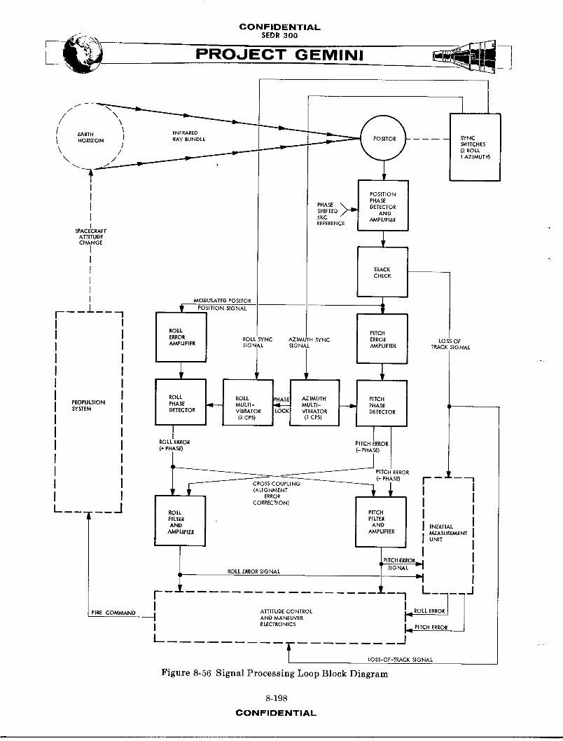
CONFIDENTIAL-- SEDR300
I _ PROJECT GEMINI
i//1" -- _ _ ]
[ EARTH _ INFRARED _ "_ P_¢,T,'_D / .... SYNC
1 RAYEUNDLE _ SWITCHES
HORIZON / _ (2 ROLL
\ / _ ] AZIMUTH)\ /
I PHASE
i PHASE DETECTORSHIFTED AND5KC AMPLIFIER
J REFERENI
SPACECRAFTATTITUDECHANGE
TRACK
CHECK
MODULATED POSITOR il_r POSITION SIGNAL
ROLL PITCH
Eg._.OR ROLL SYNC AZIMUTH SYNC ERROR LOSS OFAMPLIFIER SIGNAL SIGNAL AMPLIFIER TRACK SIGNAL
ROLL ROLL PHASE AZIMUTH PITCH
SYSTEM DETECTOR VIBRATOR VIBRATOR DETECTOR
(2 CPS) (_ CPS)
ROLL ERROR PITCH ERROR
(+ PHASE) (- PHASE)
__ PITCH ERROR
"T ......I CORRECTION,I I
FILTER FILTERAND AND INERTIAL
AMPLIFIER AMPLIFIER MEASUREMENTUNIT
SIGNAL r
ROLL ERROR SIGNAL _
l"I ATTITUDE CONTROL I_ ROLL ERRFIRE COMMAND
I AND MANEUVER
I ELECTRONICS L PITCH ERROR /
t J
f LOSS-OF-TPI._.CK SIGNAL
Figure 8-56 Signal Processing Loop Block Diagram
8-198
CONFIDENTIAL

CONFIDENTIALSEDR 300
An indirect method of controlling spacecraft attitude (on spacecraft 7) with the
Horizon Sensor involves a third spacecraft system (Inertial Guidance). This
method can be used when it is desired to fine align the inertial measurement
unit. Horizon Sensor attitude error signals are now used to continuously torque
gyros in the inertial platform, aligning them to the local vertical. The plat-
form attitude error signals are then used by the ACME (in the platform mode)
to generate fire comm_nds for the Propulsion System. Using this method of
attitude control, the spacecraft is held to within +l.1 degrees of the plat-
form attitude in all three axes.
The inertial platform can also be aligned by the Horizon Sensor without using
a servo loop. To align the platform without a closed servo loop, the pilot must
manually maintain spacecraft attitude as near n1111 as possible. (The Horizon
Sensor attitude error signals are most accurate when the spacecraft is in a
horizontal attitude with respect to the earth surface. ) Attitude error signals
are then used to torque platform gyros and have no direct effect on Spacecraft
attitude.
The Horizon Sensor System also provides a loss of track indication to both the
ACME and Inertial Guidance System. The signal is used to prevent the ACME
or platform from aligning to a false horizon. The loss of track si@nal is also
used to illuminate the SCANNER light on the pedestal, informing the pilot that
the system is not tracking. (Spacecraft attitude must be held within +20
degrees of the horizontal for the system to track. )
8-199CON FIDr:.NTIAL

CONFIDENTIAL
PROJECT GEMINI
Tracking Geometry
Horizon Sensor trackinggeometry (Figure 8-57) is composed of the elevation
angles (9) generated by the track loop and the azimuth angles (@) generated
by the azimuth drive loop. Angles are compared in time and phase to generate
an error signal proportlonalto the elevation angle change with respect to
the azimuth scan angle.
As explained in the track loop paragraph, the system will lock on in eleva-
tion and track the earth horizon. A dither signal causes the Positor to move
the system line of sight about the horizon at a 30 cps rate. The track loop
will move the Positor mirror such that the horizon is always in the center
of the dither pattern. It was also explained, in the azimuth drive loop para-
graph, that the system line of sight is continuously moved through a 160 degree
azimuth scan angle ata one eps rate.
When the spacecraft is in a horizontal attitude, the azimuth scan has no effect
on the elevation angle of the Positor as it tracks the horizon. If the space-
craft is in 8 pitch up attitude, the elevation angle (@) will decrease as the
azimuth angle (@) approaches 80 degrees forward and increase as angle _ approaches
80 degrees aft. If the spacecraft is in a pitch down attitude, the elevation
angle will increase as the azimuth angle approaches 80 degrees forward and
decrease as the azimuth angle approaches 80 degrees aft. This produces a one
cps pitch error signal which is superimposed on the 30 cps Positor dither.
If the spacecraft has a roll right attitude,the elevation angle _ll increase as
the azimuth angle approaches either limit and decrease as the azimuth angle
approaches zero from either l_m_t. If the spacecraft is in a roll left attitude
8-200CONFIDENTIAL
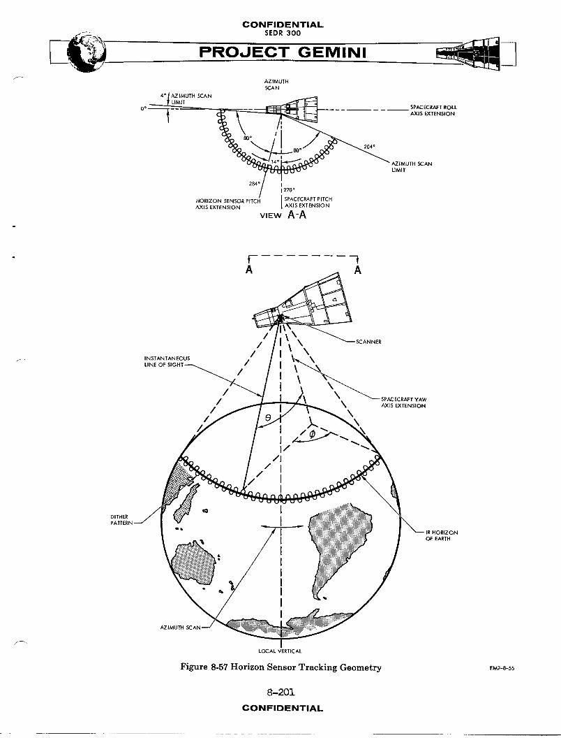
CONFIDENTIAL
PROJECT GEMINI
AZIMUTHSCAN
4° AZIMUTH SCANLIMIT
__ _ SPACB_RAFT ROLL
0° l _ - AX,S.TENSION204 °
_ AZIMUIH SCAN
LIMIT
284° I1270°
HORIZON S JAXIS EXTENSIONAXIS EXTENSION
view A-A
// \ SCANN,R
/ \INSTANTANEOUS \LINE OF SIGHT /
----.< ,/ _
/ X SPACECRAFT YAWAXIS EXTENSION
/ \
/ )..I
I//I
/ III
DITHER
J OF EARTH
IIII
=. II
AZIM
LOCALVERnCAL
Figure 8-57 Horizon Sensor Tracking Geometry F_-s-55
8-201
CONFIDENTIAL
CONFIDENTIAL
_. SEDR300
PROJ E---C'TGEM IN I
the elevation angle will decrease as the azimuth angle approaches either limit
and increase as the az4n-lthangle approaches zero from either 14m4t. This pro-
duces a two cps error signal which is superimposed on the 30 cps Positor dither.
Position Phase Detector
The Positor position phase detector compares the Positor pickoff signal with a -.
5 KC reference to determine the angle of the Positor mirror. (The mirror angle
w_11 be changing at a 30 cps dither rate, plus, if there is any spacecraft atti-
tude error, a one and/or two cps error signal rate.) The phase detector output is
then amplified and applied to the track check circuit.
Track Check
The track check circuit determines when the horizon is in the field of view. If
the horizon is in the field of view,the track check circuit energizes a relay.
Contacts of this relay connect the Positor position signal to the pitch and roll
error amplifiers. A second relay in the track check circuit, energized when the
system is not tracking, provides a loss of track indication to the inertial mea-
surement ,,4t and the ACME. The loss of track signal is 28 volts DC obtained
through the ATT IND CNTL-LDG circuit breaker and switched by the track check
circuit.
Error Amplifiers
In order to obtain individ-A1 pitch and roll attitude error outputs, error signa_
separation must be accomplished. This function is performed by two error ampli-
fiers. The Positor position signal input to the error _lifiers is a composite
30 cps dither, one eps pitch error and two cps roll error signal. The pitch error
amplifier is tuned to one cps and selects the pitch ez_z_rsignal only for
8-20ECONFIDENTIAL

GONFIDENTIAL
SEDR300
PROJECT-'-GEMINI
amplification. The roll error amplifier is tuned to two cps and selects the roll
error signal only for amplification. Each amplifier then =mplifies and inverts
their respective signals, producing two outputs each. The outputs are 180 degrees
out of phase and of the same frequency as their input circuits were tuned. Output
of each error amplifier is coupled to its respective phase detector.
l___e Detectors
Phase detectors compare the phase of pitch and roll error signals with one and two
cps multivibrator reference signals to determine the direction of attitude error.
The multivibrators are synchronized with motion of the azimuth drive yoke by three
sync switches. Two sync switches, located at 57 degrees on either side of the cen-
ter position of the yoke, synchronize the roll multi_lbrator with the motion of the
yoke and set its frequency at two cps. The sync switches close each time the yoke
passes, in either direction, producing four pulses for each cycle of the yoke.
Each time a pulse is produced it changes the state of the multivibrator resulting
in a two cps output. The azimuth multivibrator operates in the same m_nner except
that it only has one sync switch, located at the center of the drive yoke scan,
resulting in a one cps output frequency. The azimuth multivibrator also provides
a phase lock signal to the roll multivibrator to assure not only frequency synch-
ronization but correct phasing as well. The phase detectors themselves are act-
ually reed relays, two for each detector_ which are energized alternately by their
respective multivibrator output signals. Contacts of these relays combine the two
input signals in such a manner that two fUll wave rectified output signals are
produced. The polarity of these pulsating DC outputs indicates the direction and
r the amplitude indicates the _mount of attitude error about the Horizon Sensor pitch
and roll axes. Since the sensor head was mounted at a 14 degree angle with
8-20SCONF'DENT,AL
CONFIDENTIAL
' PROJECT GEMINI
respect to the spacecraft, the mounting error must be compensated for. Electrical
rotation of the Horizon Sensor axes, to correspond with spacecraft axes, is accom-
plished by cross coupling a portion of the pitch and roll error signals.
Output Amplifier and Filter
The output amplifler-filter removes most of the two and four cps ripple from the
rectified attitude error signals and amplifies the signals to the required level.
The identical pitch and roll operational amplifiers, used as output stages for the
Horizon Sensor System, are _Igbly stable and have a low frequency response. The
output signal amplitude is four tenths of a volt for each degree of spacecraft
attitude error. The signals are supplied to the ACME for spacecraft alignment and
to the inertial measurement unit for platform alignment.
HORIZON SENSOR POkiER
Horizon Sensor power (Figure 8-58) is obtained from the 28 volt DC spacecraft bus
and the 26 volt AC, _00 cps ACME power. The 28 volt DC power, supplied through the
SCAN _ switch, is used to maintain temperature in the sensor head and as power
for the SCAHRER l_mp. Sensor head heaters are thermostatically controlled and
operate any time the SCAN HTR switch is on. The 26 volt AC, 400 cps ACME power is
provided by either the IGS or ACME inverter, depending on the position of the AC
POWER selector. The 26 volt AC is used to produce seven different levels of DC
voltage used in the Horizon Sensor. One of the voltages (31 volts DC) is obtained
by rectifying and filtering the 26 volt AC input. The remaining six levels are
obt_Ined by transforming the 26 volts to the desired level, then rectifying, fil-
tering and reg,,latingit as required. The minus 27 volts DC output is used to
excite one side of the bolometer bridge. The other side of the bridge is excited
8-204CONFIDENTIAL
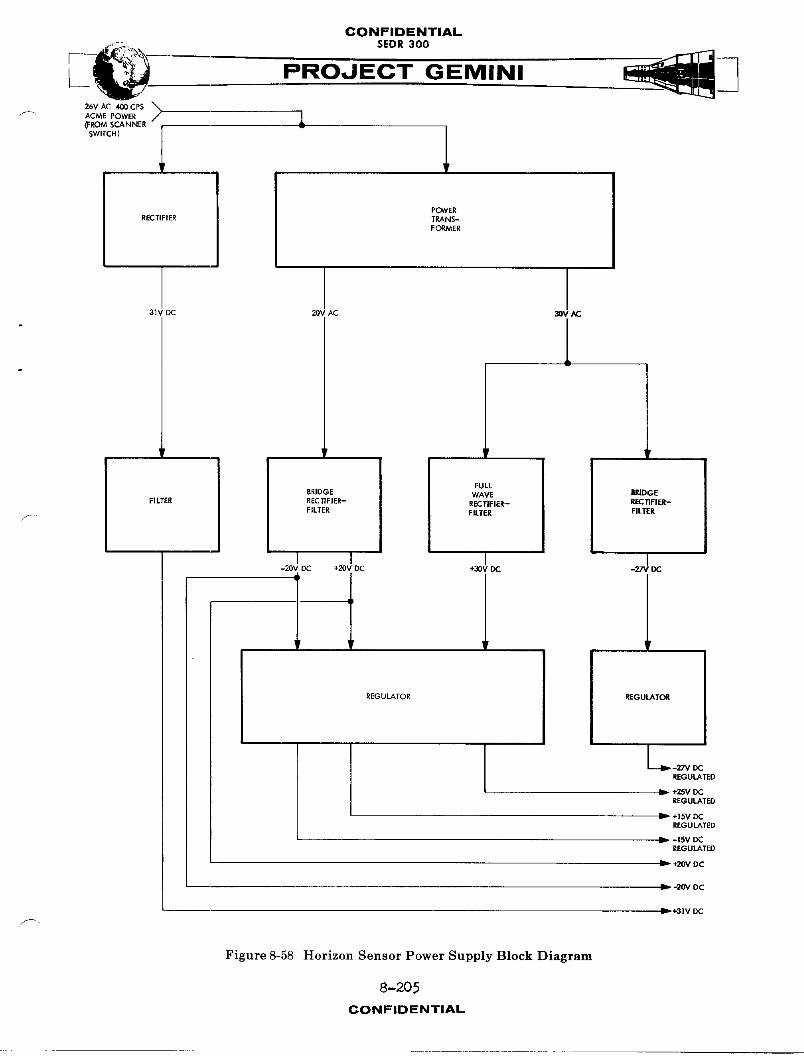
CONFIDENTIAL
F--- ":i_",'--_,, SEDR 300 __26V AC 400 CPS
ACME POWER // |_:ROM SCANNER 6
SWITCH)
POWERRECTIFIER TRANS-
FORMER
31V DC 20V AC 30V AC
'r ,r * [
FULL 1
BRIDGE WAVE BRIDGEFILTER RECTIFIER- RECTIFIER_ RECllFIER-
FILTER FILTER FILTER
-20V DC +20V DC +30V DC -27V IX:
REGULATOR REGULATOR
_,- -27V DC
REGULATED
+2._V DCREGULATED
I1_ +15V DCREGULATED
I1_ -15V DCREGULATED
+20V DC
-20V DC
_--- _'31V DC
Figure 8-58 Horizon Sensor Power Supply Block Diagram
8-205
CONFIDENTIAL

CONFIDENTIAL
• ,%_ SEDR 300 __PROJECT GEMINI
by plus 25 volts DC. Plus 25 volts DC is also used for transistor power in the
error amplifiers. The 31 volt DC unregulated output is used as excitation for the
azimuth drive yoke. The remaining four voltages (+15, -15_ +20, -20) are all used
for transistor power in the various electronic modules.
SYSTEM UNITS
The Horizon Sensor System (Figure 8-49) consists of two major units and _ive minor
units. The minor u_Its are: three switches, an indicator light and a fiberglass
fairing. The three s_itches are mounted on the control panels for pilot actuation.
The indicator light is mounted on the pedestal and, when illuminated, indicates a
loss of track. The fiberglass fairing is dust proof and designed to protect the
sensor heads, which it covers, from accidental ground damage or thermal damage dur-
ing launch. The two major units are: the sensor head and the electronics package.
SENSOR HEAD
The sensor head (Figure 8-50) is constructed from a magnesium casting and contains
a Posltor, a telescope-filter assembly, a signal preamplifier, a position detector,
an active filter and an azimuth drive yoke. The Posltor (Figure 8-59) is a mirror
positioning assembly designed to position a mirror about its elev_tlon axis. The
mirror is polished beryllium and is pivoted on ball bearings by a magnetic drive.
The Posltor also includes a position pickoff coll for determining the angle of the
Posltor mirror.
The telescope-filter assembly (see Figure 8-53) contains a fixed mirror, a germa-
nium meniscus lens, an infrared filter and a germanium _mmersed thermistor bolom-
eter. The fixed mirror is set at a 45 degree angle to reflect radiation from the
8-206CONFIDENTIAL
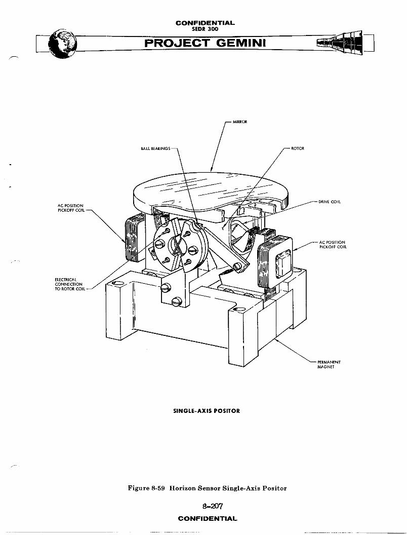
CONFIDENTIALSEDR 300
MIRROR
L COfLAC POSfflON
P,cKoFFco,L--POSITION
L..I PICKOFF COIL
ELECTRICALCONNECTIONTO ROTOR
SINGLE-AXIS POSITOR
Figure 8-59 Horizon Sensor Single-Axis Positor
8-2O7CONFIDENTIAL

CONFIDENTIAL
PROJECT GEMINI
Positor mirror into the telescope. The germanium meniscus objective lens of the
telescope is designed to focus incoming infrared radiation on the bolometer. The
infrared filter, located imN_diately behind the objective lens, is designed to pass
infrared radiation in the 8 to 22 micron range. The germanium immmrsed thermistor
bolometer contains a culmlnating lens and two thermistors. The culminating lens
directs all incoming radiation on one of the thermistors. The two thermistors are
bonded to the rear of, and effectively _m,_rsed in, the culminating lens. Both
thermistors are identical; however, one of the thermistors (active) is located at
the focal point of the culminating lens. The other thermistor (passive) is located
to one side of the focal point. The passive thermistor is used as an ambient
temperature reference and does not react to direct infrared radiation.
Si6nal Preamplifier
The signal preamplifier is a low noise, hlgh gain, four stage, direct coupled
transistor amplifier. The preamplifier is made in modular form and potted in
epoxY for thermal conductivity and protection from shock and vibration.
Position Detector
The position detector is a five KC phase detector designed to determine the
position of the Positor m_rror. The circuit produces a voltage which is
proportional to the angle of the Positor mirror. Output of the detector is
a DC voltage which varies at the same rate as the Positor mirror moves. The
detector is made in modular form and potted in epoxY for thermal conductivity
and protection from shock and vibration.
8-208CONFIDENTIAL

CONFIDENTIAL
___ SEDR300
PROJECT GEMINI
Azimuth Drive Yoke,,
The azimuth drive yoke provides a means of moving the Positor mirror about
its azimuth axis. The yoke is magnetically driven and pivots on ball bearings.
The Posltor is mounted inside the azimuth drive yoke and is rotated through
an azimuth scan angle of 160 (+-80)degrees by the yoke. The azimuth axis of
rotation is through the center line of the infrared ray bundle on the surface
of the Positor mirror. Drive coils, located directly in front of the yoke,
supply magnetic impulses to drive the yoke. Mounted on the edge of the yoke
(see Figure 8-55)are two iron slugs and a permanent magnet. The iron slugs
are used to induce an overshoot signal in the azimuth overshoot detector.
The permanent magnet is used to synchronously close contacts on three sync switches,F_
mounted around the periphery of the yoke.
ELECTRONICS PACKAGE
The electronics package (Figure 8-51) contains the circuitry necessary to
control the azimuth yoke and Positor in the sensor head, as well as process
attitude error signals. The package also contains a DC power supply and a
five KC field current generator. The solid state circuitry is made in modular
form and potted in epoxy for thermal conductivity and protection from shock and
vibration.
8-209/-210CONFIDENTIAL
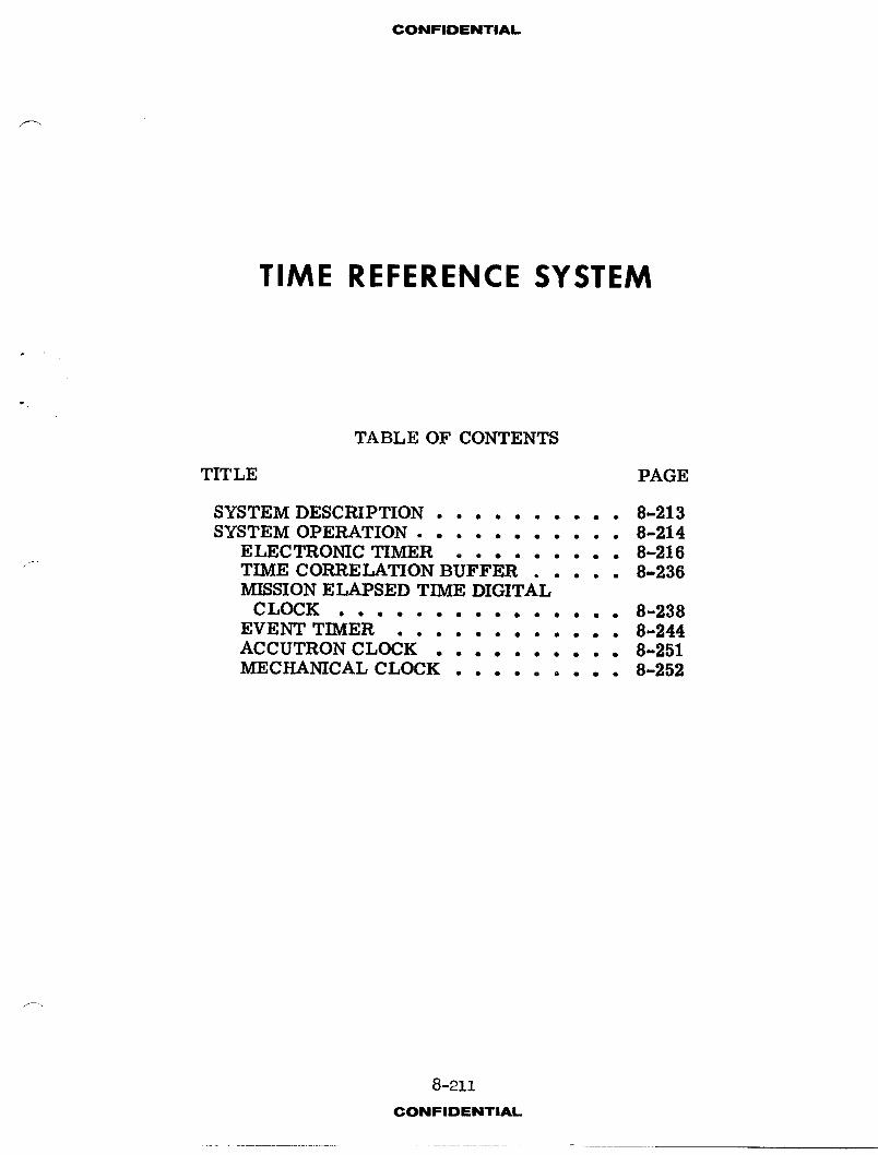
CONFIDENTIAL
TIME REFERENCE SYSTEM
TABLE OF CONTENTS
TITLE PAGE
SYSTEM DESCRIPTION .......... 8-213SYSTEM OPERATION ........... 8-214
ELECTRONIC TIMER ......... 8-216TIME CORRELATION BUFFER .... 8-236MISSION ELAPSED TIME DIGITAL
CLOCK ............... 8-238EVENT TIMER ............ 8-244ACCUTRON CLOCK .......... 8-251MECHANICAL CLOCK ......... 8-9.52
8-211
CONFIDENTIAL
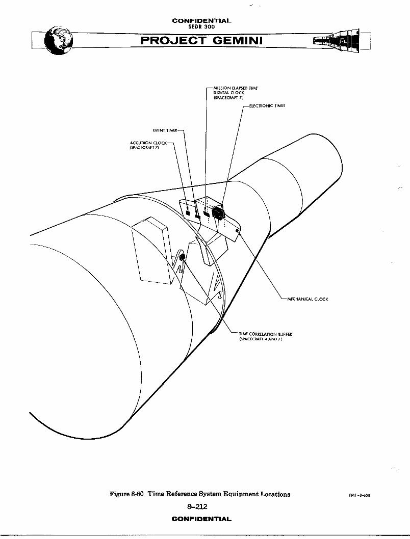
CONFIDENTIAL
s o.ooPROJECT GEMINI
DIGITAL CLOCk'
(SPACECRAFT 7)
IMER
(SPACECRAFT 7)
'MECHANICAL CLOCK
TIME CORRELATION BUFFER(SPACECRAFT 4 AND 7 )
Figure 8-60 Time Reference System Equipment Locations FM_-a_0s
8-212
CONFIDENTIAL
CONFIDENTIAL
PROOECT GEMINI
TIME REFERENCE SYS_
SYSTEM I_ESCRIPTION
The Time Reference System (TRS) (Figure 8-60) provides the facilities for
performing all timing functions aboard the spacecraft. The system is comprised
of an electronic timer, a time correlation buffer, a mission elapsed time
digital clock, an event timer, an Accutron clock and a mechanical clock. The
event timer, mission elapsed time digital clock, Accutron clock and mechanical
clock are all mounted on the spacecraft instrument panels. The electronic timer
is located in the area behind the center instrument panel and the time correla-
tion buffer is located in back of the pilot's seat.
The electronic timer provides (I) an accurate countdown of time-to-go to retro-
fire (TTG to T2) and tlme-to-go to equipment reset (TTG to TX), (2) time correla-
tion for the PCM data system (Instrumentation) and the bio-med tape recorders,
and (3) a record of elapsed time (ET) from llft-off.
The Time Correlation Buffer (TCB), used on spacecraft (S/C) 4 and 7, conditions
certain output signals from the electronic timer, m_klng them compatible with
blo-med and voice tape recorders. Provision is included to supply buffered
signals for Department of Defense (DOD) experiments if required.
The mission elated time digital clock (on S/C 7) provides a digital indication
of elapsed time from L_ft-off. The digital clock counts pulses from the elec-
tronic timer and is therefore started and stopped by operation of the elec-
tronic timer.
8-213CONFIDENTIAL
CONFIDENTIALSEDR 300
The event timer provides the facilities for timing various short-term functions
aboard the spacecraft. It is also started at lift-off to provide the pilots
with a visual display of ET during the ascent phase of the mission. In case
the electronic timer should fail, the event timer may serve as a back-up
method of timing out TR.
The Aecutron clock (on S/C 4 and 7) provides an indication of Greenwich Mean
Time (GMT) for the comm_nd pilot. The clock is powered by an internal battery
and is independent of external power or signals.
The mechanical clock provides the pilot with an indication of GMT and the
calendar date. In addition, it has a stopwatch capability. The stopwatch provides
an emergency method of performing the functions of the event timer.
SYSTEM OPERATION
Four components of the Time Reference System (electronic timer, event timer,
Accutron clock and mechanical clock) function independently of each other.
The two remaining components (m_ssion elapsed time digital clock and time
correlation buffer) are dependent on output signals from the electronic timer.
A functional diagram of the Time Reference System is provided in Figure 8-61.
The electronic timer, mission elapsed time digital clock, Aceutron clock and the
time-of-day portion of the mechanical clock operate continuously, during the
spacecraft mission. The mechanical clock and Accutron clock are started during
the pre-launch period. The electronic timer starts operating upon receipt of
a remote start signal from the Sequential System at the time of lift-off.
8-214CONFIDENTIAL
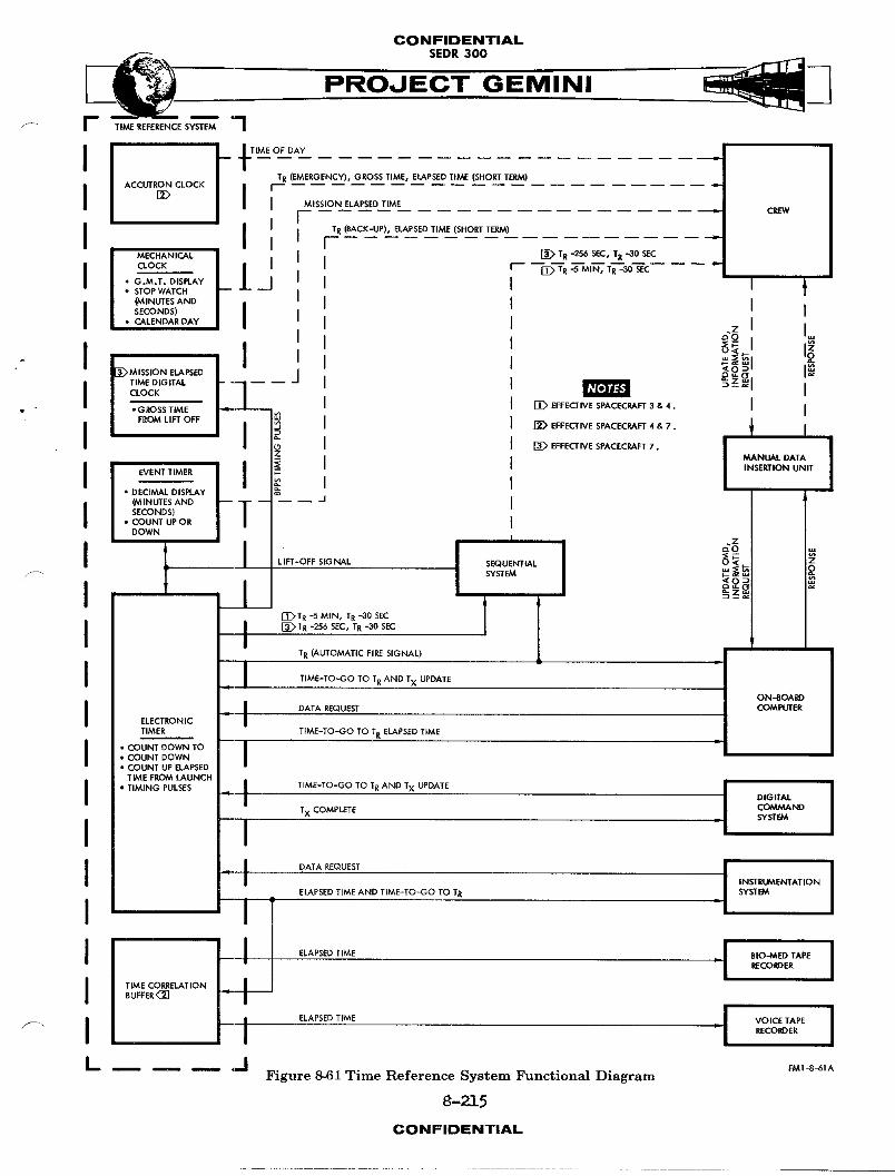
CONFIDENTIAL
PROJECT GEMINI
ACCUTRON CLOCK TR (EMERGENCY)I GROSS TIMEs ELAPSEDTIME (SHORT TERM)
J MISSION ELAPSED TIME CREW
I I I TR(SACK-,.,P_.E'.APSED'r,ME_S.ORTT_,)j ............ •
MECHAN,t. [
j aocK I r-- --_-_'R _--MIN,TR---3OSEC "• G.M.T.D,SPLA¥ _.J• STOP WATCH
_AINUTES AND
I SECONDS) I
• CALENDAR DAY O"Z I=
M,SS,ONELAPSED j __J TIME DIGITAL
CLOCK
FROM LIFT OFF
I", . [J_ EFFECTIVE SPACECRAFT 3 & 4.. J
I _ EFFECTIVE SPACECRAFT 4 & 7. JI
• DECIMAL DISPLAy(MINUTESAND -- -- -- /SECONDS)
• COUNT UP OR
DOWN I _Z
I I , ,[T_T R -5 MINI TR --30 SEC | |
I I [_ TR -256 SEC' TR -30 SEC
/ L r
T R (AUTOMATIC FIRE SIGNAL)
-_- I TIME-TO-GO TO T RAND TX UPDATE
ON-BOARD
J l DATA REQUEST COMPUTER
ELECTRONIC J
TIMER TIME-TO-GO TO TR ELAPSED TIME
** COUNT DOWN TO JCOUNT DOWN
• COUNT UP ELAPSEDTIME FROM LAUNCH
TIMING PULSES -_- J TIME-TO-GOTxCOMPLETETO TR AND Tx UPDATE J DIGITALCOMMAND I__ J _ SYSTEM
I
INSTRUMENTAT ION
ELAPSED TIME AND TIME-TO-GO TO TR SYSTEMl=
_, -- m RECORDER
L m J _ a,J FMI_I_,IA
Figure 8-61 Time Reference System Functional Diagram
8-215
CONFIDENTIAL
CONFIDENTIAL
PROJECT GEMINI
If the lift-off signal is not received from the Sequential System, the elec-
tronic timer can be started byactuation of the START-UP switch on the event
timer. The mission elapsed time digital clock and time correlation buffer
start operating upon receipt of output signals from the electronic timer.
During the mission, the event timer, Accutron clock and the stopwatch portion
of the mechanical clock can be started and stopped, manually, at the descretion
of the crew. At lift-off, however, the event timer is started by a remote
signal from the Sequential System.
_T._CTRONICTIMER
General
At the time of lift-off, the electronic timer begins its processes of counting
up elapsed time and counting down TTG to TR and TTG to TX. ET is counted up
from zero to a maximum of approximately 2_ days. The retrofire and equipment
reset functions are counted down to zero from certain values of time which are
_itten into the timer prior to lift-off. The timer is capable of counting
TTG to TR from a maximum of 24 days and to equipment reset from a maximum of
two hours.
The TTG to TR data contained by the timer may be updated at any time during
the mission by insertion of new data. Updating may be accomplished either by
a ground station, through the Digital Conmmnd System (DCS), or by the crew,
via the Manual Data Insertion Unit (MDIU) and the digital computer. To prevent
inadvertent, premature countdown of TR as a result of equipment failure or
personnel error during update, the timer will not accept any new time-to-go
8-2_CONFIDENTIAL
CONFIDENTIAL
-i__- SEDR 300 __
PROJECT GEMINI/
of less than 128 seconds duration on S/C 7 or 512 seconds on S/C 3 and 4. Upon
receipt of new data of less than the i_h_bit time mentioned above, the timer
will cause itself to be loaded with a time in excess of two weeks.
The TTG to TX function of the timer serves to reset certain equipment which
operates while the spacecraft is passing ever a ground station equipped with
telemetry. As the spacecraft comes within range, the ground station inserts,
via the DCS, a TTG to TX in the timer. Then, as the spacecraft moves out of
the range of the ground station, the TTG to TX reaches zero, and the equipment
is automatically reset. If the ground station is unable to insert the time
data, it may be done by the crew, using the MDIU and digital computer.
Information from the electronic timer is not continuously displayed; however,
confirmation of satisfactory operation may be made by the readout of TR data
through use of the digital computer MDIU display readout capability.
NOTE
The mission elapsed time digital clock
counts pulses from the electronic timer
and, assuming no loss of pulses, will
indicate the elapsed time recorded in
the electronic timer. The digital clock
does not, however, read out the elapsed
time word from the electronic timer.
8-217CONFIDENTIAL

CONFIDENTIALSEDR 300
Construction
The electronic timer (Figure 8-62) is approximately 6" x 8 3/4" x 5 1/2" and
weighs about ten pounds. It has two external connectors for interface _rlth
its associated systems. The enclosure for the unit is sealed to keep out
moisture but is not pressurized. The timer utilizes a modular construction,
containing eight modules which are wired directly into the enclosure. The modules
are: (i) crystal oscillator, (2) t_m_ng assembly, (3) register control assembly,
(4) memory control assembly, (5) memory assembly, (6) driver assembly, (7)
relay assembly, and (8) power supply. Printed circuit boards and solid state
components are used in All modules except the crystal oscillator.
Operation
The electronic timer is basically an electronic binary counter. It performs the
counting operation for each of its functions (ET, TTG tO TR, and TTG to TX)
by an add/subtract program which is repeated every 1/8 second. (Refer to
Figure 8-63). In each repetition of the counting operation, a binary word,
representing ET or a TTG, is modified to represent a new amount of time.
Magnetic core storage registers are used to store or remember the binary words
between counting cycles. A storage register is provided for each of the three
timer functions and another is provided for use as a buffer register for
data transfer between the timer and the digital computer.
A crystal controlled oscillator is used as a frequency standard for developing
the timing p_]_es necessary for the operation of the timer. This type of
oscillator provides the high degree of accuracy required for the timer whose
8-218CONFIDENTIAL
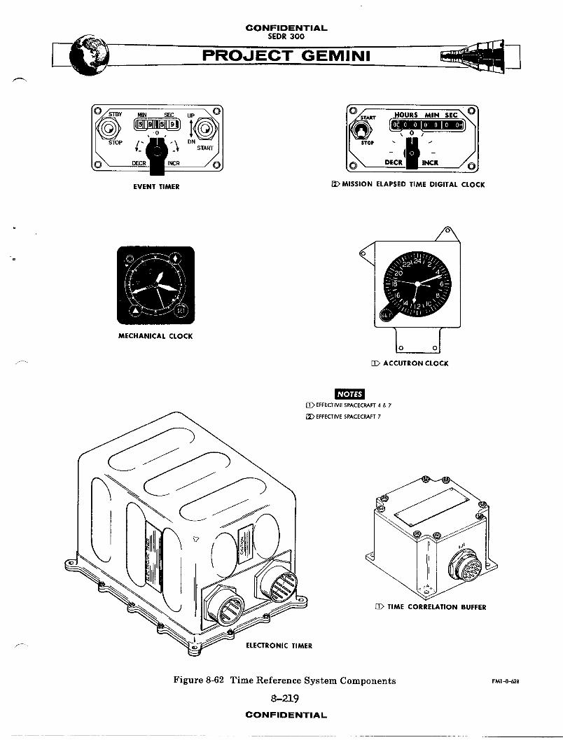
CONFIDENTIAL
PROJECT GEMINI
HOURS MIN SEC_
,oolm
EVEN; TIMER _MIS$1ON ELAPSED TIME DIGITAL CLOCK
A
// 1DIMECHANICAL CLOCK lO OI
[D ACCUTRON CLOCK
[_ EFFECTWESPACECRAFT4 & 7
EFFECTIVESPACECRAFT7
[_ TIME CORRELATION BUFFER
,/_- ELECTRONIC TIMER
Figure 8-62 Time Reference System Components FM1-8"62.fi
8-219
CONFIDENTIAL
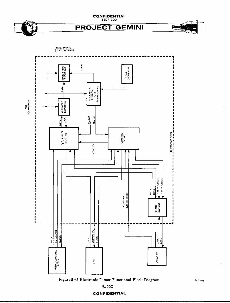
CONFIDENTIAL5EDR 300
TIMED EVENTS
(RELAy CLOSURES)
Figure 8-63 Electronic Timer Functional Block Diagram FMG2-137
8-220
CONFIDENTIAL

CONFIDENTIAL
-_ SEDR 300 __._PROJECT GEMINI
_operations take place in very small fractions of a second. The oscillator is
coupled to a series of toggle flip flops whose outputs provide the actual timing
pulses for the timer operation.
The electronic timer utilizes a 32-word time program. That is, each 1/8 second
of time is further divided into 32-word times. Each word time is divided into
32 bit times, and each bit time is divided into 32 "S" pulse times. "S" pulses
are the shortest pulses used in the timer operation and are 3.8 microseconds
long. One bit time is equal to ]22 microseconds and one word time 3.9 milli-
seconds. It is pulses of these durations, and their multiples, which are
produced by the toggle flip flops in the timing module.
Timer Start Circuit
Timer operation is initiated when a 28VDC start signal is received from either
the spacecraft Sequential System or the event timer. The signal from the
Sequential System is transmitted to the electronic timer, automatieA!ly, at
lift-off; the one from the event timer is generated when the UP/DN toggle switch
on the face of the unit is placed in the UP position. Receipt of a signal from
either source causes the set side of the clock-start relay to be actuated.
Until lift-off, the relay is held in the reset position by a clock-hold signal
from the AGE via the spacecraft umbilical. This is done to assure that the
timer will not be started prematurely andwillbe at zero at the time of lift-off.
Actuation of the clock-start relay causes a positive control signal to be applied
to a gate in the timing module. This gate allows the output of the crystal
controlled oscillator to be coupled to the countdown flip flops.
8-221CONFIDENTIAL

CONFIDENTIAL
PROJECT GEMINI
Countdown and Time Decodin_
The countdown and time decoding operations take place primarily in the timing
module. When timer operation is initiated, the 1.048576 megacycle output of
the crystal-controlled oscillator is coupled to the first of a series of 17
toggle flip flops (refer to Figure 8-64). Twelve of the flip flops are contained
in the timing module and five in the register control module. The flip flops
form a frequency dividing network, each stage of which produces one square ';
wave output pulse for every two input pulses. The output frequency of the final
stage in the series is eight pulses per second.
Outputs of all but the first tw_ostages of the countdown circuitry are utilized
to develop the timing pulses necessary for timer operations. Output p_1 ses
from either the "l" or the "0" side of an individual flip flop may be used;
however, the polarity of the pulses from one side will be 180° out of phase
with those from the other side. Pulses from the flip flop outputs are supplied,
in certain combinations, to gate circuits in the time decoding section. Each
gate circuit receives several input pulse trains and produce output p,_l_es which
are usable for the timer circuitry (refer to Figure 8-65a). Basically, a gate
will produce output pulses which w_11 have the pulse width of the narrowest
input pulses and the frequency of the input In11_e train with the widest pulses.
If the polarity of one input is reversed, the time at which the output pulse
occurs, will change (refer to Figure 8-65b).
8-222CONFIDENTIAL
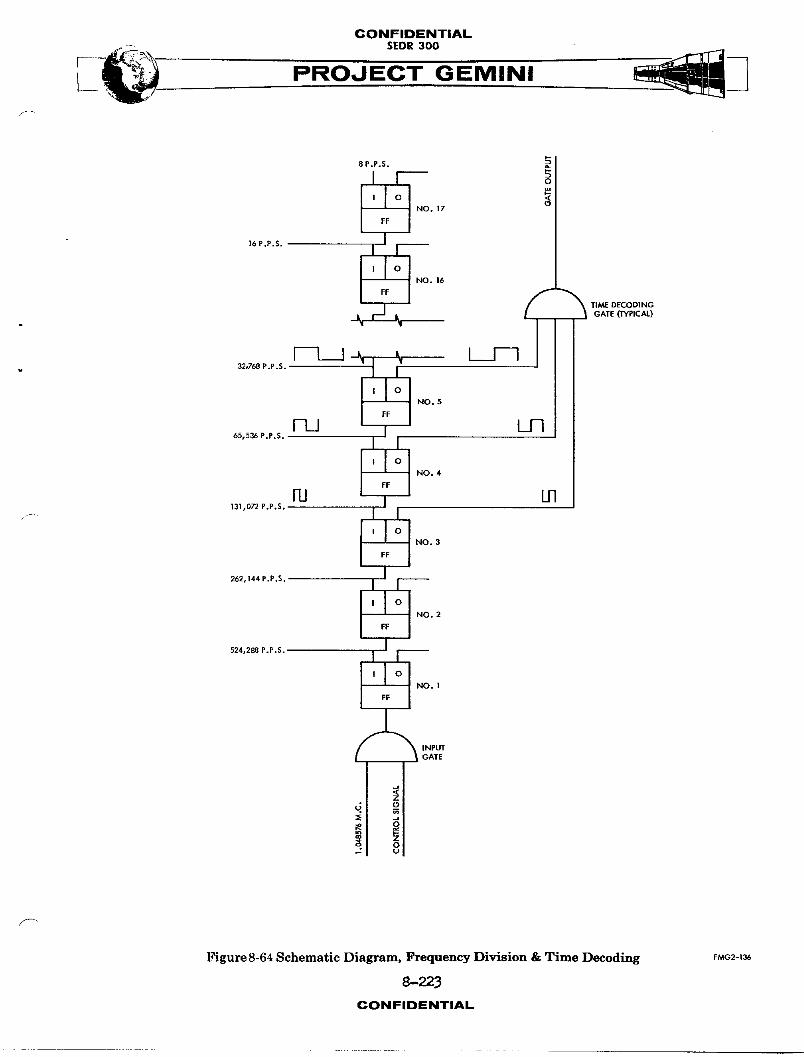
CONFIDENTIAL
SEO,,oo___ PROJECT GEMINI
P-8P.P.S.
p.
NO. 17 (_
]6 P.P.S* ._LI_I_I_I_EJ_'_J NO. 16
I FI
ll_/dE DECODING
. -._ r- _(__ _ GATE (TYPICAL)
32,768 P.P .S. J J_l O'_
NO. 5
65,536 P.P.S.
131,072 P.P.S. I " i
NO. 3
262,144 P.P.S.
NO.2524,288 P.P.S.
NO. 1
INPUTGATE
d __ 0
Z
Figure 8-64 Schematic Diagram, Frequency Division & Time Decoding FMG2-136
8-223CONFIDENTIAL
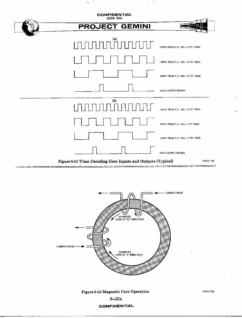
CONFIDENTIAL--- SEDR300
(a)
INPUT FROM F.F. NO. 3 ("O" SIDE)
II I I I I I I I I I 'NFUTEROMF.E._O.4_"O"S'OE,I _ I i I ,NFDTEROM..OO.5_"O"S,DE,
--1 J-_ GATE OUTPUT SIGNAL
(b)
INPUT FROM F.F, NO. 3 ("O'* SIDE)
I I L L_I--11I I I I ,NFUTFROME.E.NO._","_'DE)
I 7----1 r--1 I ,_0_,o_._.oo._..o.._,00
Figure 8-65 Time Decoding Gate Inputs and Outputs (Typical) FMG2-1_
__ CURRENT PULSE
SATLIRATESCORE IN =O" DIRECTION
SATURATESCORE IN "I"DIRECTION
Figure 8-66 Magnetic Core Operation FMG2-133
8-22L_
CONFIDENTIAL
CONFIDENTIALSEDR300
/
Operational Control
Two complete modules are required to encompass _11 of the circuitry necessary to
perform the control functions in the electronic timer. The register control
module primarily controls the transfer of data into and out of the timer.
The memory control module directly controls the operations of the magnetic
storage registers in the memory module.
The register control module supplies the control signals which are required to
perform the operations directly associated with the transfer of time data.
It utilizes the various co,,,nndand clock signals from the other spacecraft
system_ to produce its control signals. The control signals are then supplied to
the appropriate circuitry to: (i) receive a new binary data word (as in thef
updating process), (2) initiate the shifting operations of the proper storage
registers to "write" in or "read" out the desired time data (ET, TR, or TX), and
(3) supply data, read out of the storage registers, to the proper timer output
terminal(s) to be transferred to the system requesting it.
The memory control module directly controls the operation of the magnetic storage
registers and performs the arithmetic computations of the counting process.
Inputs from the timing and register control modules are utilized to develop
the shift and transfer output pulses for shifting data words into and out
of the storage registers. These pulses are developed separately for each register.
/
8-225CON FIDENTIAL
CONFIDENTIALSEDR300
Both control modules are made up of rather complex and overlapping networks
of logic circuitry. The memory control module also employs shift current
generators and transfer switches, as output stages, to develop the required
power capabilities.
Storage Register Operation
The magnetic storage registers for ET, TR, and TX are used to store or remember
binary words of time data. These data words may be shifted out of their respec-
tive registers, as required, for the counting operations and for transfer to
other spacecraft systems. The transfer of data into and out of a storage regis-
ter is accomplished, serially, with the Least Significant Bit (LSB) first.
A storage register is comprised of a series of magnetic memory cores, each of
which is capable of storing one binary bit of time data. This capability is
based upon the characteristic of a magnetic core to saturate in one of two direc-
tions when a current p_1_e is applied to one of its windings. (Refer to Figure
8-66. ) Saturation in one direction represents a binary "l" and indicates the
presence of a data bit. Saturation in the other direction represents a binary
"0" and indicates the absence of a data bit. The storage registers for ET
and TTG to TR each contain 24 magnetic cores and the register for TTG to Tx
contains 16. Therefore, a binary word for ET or TR consists of 24 bits, while
a word for Tx consists of 16 bits.
The use of the binary system for time representation permits the storage of
data which can represent an amount of time as small as 1/8 second and as large
as 24 days. Each data bit in a binary data word represents one individual
8-226CONFIDENTIAL
CONFIDENTIAL
SEDR300
PROJEC--'T'-'G EMINI
increment of time. In looking at the flow diagram in Figure 8-67a the 24 sec-
tions of the storage register represent its 24 individual cores. The data bit
which represents the smallest time increment (1/8 second) is stored in core
number 24. It is referred to as the LSB in the data word. Core number 2B, then,
would store the next bit (representing 1/4 of a second) of the data word.
The sequence continues, with core number 22 representing 1/2 second, back through
. core number 1 with each successive core representing a time increment twice
that of the preceding one. By adding together the increments of time repre-
sented by all of the cores, the total time capacity of the register can be de-
termined. Thus, it is found that the ET and TR registers have capacities of
approximately 24 days and the Tx register, approximately two hours. Conversionf--
of a data word to its representative time may be accomplished by totaling the
increments of time represented by the bit positions of the word where binary
ones are present. For the data word shown in Figure 8-67b the representative
time is 583 3/8 seconds.
The process of shifting a data word into or out of a storage register is controlled
by the occurrence of the shift and transfer pulses and by the condition of a
control gate preceding each register and its _mite-in amplifier. The shift and
transfer pulses from the control section are supplied to a storage register
whenever a data word is to be written in or read out. These _,1_es occur
once each bit time for a duration of one word time. The actual flow of data
into a storage register is controlled by a logic gate preceding the write-in
amplifier for each register. (Refer to Figure 8-68.) The count enable
input of the gate will have a continuously positive voltage applied after lift-off
has occurred. The write-in pulse input will have a positive pulse applied for
8-227CON FIDENTIAL
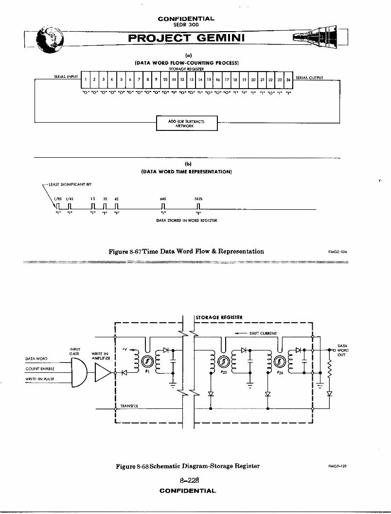
CONFIDENTIALSEDR 300
(o)
(DATA WORD FLOW-COUNTING PROCESS)STORAGE REGISTER
"0" "O" "O" "O" "O" "O" "O" "O" "O" "O" "1" "O" "O" "1" "O" "O" "0" "l" "1" "1" "1" "O" "1" "1"
J ADD (OR SUBTRACT) tNE']WORK
(b)
(DATA WORD TIME REPRESENTATION)¢.
LEAST SiGNiFICANT BIT
_I/8S I/4S 1 S 2S 4S 64S 512S
"_N I1 _ !1 I1
DATA STORED IN WORD REGISTER
Figure 8-67 Time Data Word Flow & Representation FMG2-134
:_:i _i:_:_:_:__:i_:!__:!:!:i:i:i:!:_:i:___:___i:_:___:?_:_ _:>___:__ _:__:i:_:?_ __ ___i_ _%_i_ __i_ :_:_ _ _ _$?__-_:_%!_!:!_:i_i:__:!:!:!__:!_i:!-_-<_:_:___:_.__:!:!__:!:!_c_::___:__i:_i:__:i_:_:_:_:i:_!:!:_:_:_:_:_:_:_:_:_:_i:_:i:!_:!::!:!:!:!:!:!:!:!:!::_:!::!:_::_:i:i:::i:_:_::_:_:_::_:i_::__:i:i::!_:!:_:!:_:i::_:!_!:!:!_:!:!:!:!:!:!:::!:!:_:_:_:__:____:_:_:_:__:_:i:_i:_:i:ii:__:i:_:i:_:!:_i
STORAGE REGISTER
[ 1
INPUT ! +V ] _-O WORD
GATE WRITEIN OUT
DATA WORD _ AMPLIFIER I
COUNT ENABLE #23 _ *" 124
WRITE-IN PULSE
T NSEERI II I
Figure 8-68 Schematic Diagram-Storage Register EUG_-_
8-228CONFIDENTIAL
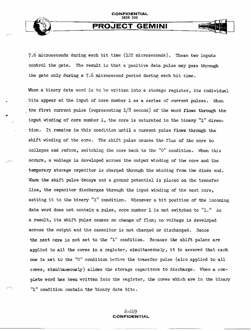
CONFIDENTIAL
PROJECT GEMINI
7.6 microseconds during each bit time (122 microseconds). These two inputs
control the gate. The result is that a positive data pulse may pass through
the gate only during a 7.6 microsecond period during each bit time.
Nhen a binary data word is to be _¢ritten into a storage register_ its individual
bits appear at the input of core number 1 as a series of current pulses, i.Zhen
the first current pulse (representing 1/8 second) of the word flows through the
input _¢inding of core number l, the core is saturated in the binary "l" direc-
tion. It remains in this condition until a current pulse flows through the
shift _nding of the core. The shift pulse causes the flux of the core to
collapse and reform, switching the core back to the "0" condition. When this
F_ occurs, a voltage is developed across the output _rinding of the core and the
temporary storage capacitor is charged through the winding from the diode end.
When the shift pulse decays and a ground potential is placed on the transfer
line, the capacitor discharges through the input winding of the next core,
setting it to the binary "l" condition. Whenever a bit position of the incoming
data word does not contain a pulse, core number 1 is not switched to "l." As
a result, its shift pulse causes no change of flux; no voltage is developed
across the output and the caoacitor is not charged or discharged. Hence
the next core is not set to the "l" condition. Because the shift pulses are
applied to all the cores in a register, simultaneously, it is assured that each
one is set to the "0" condition before the transfer pulse (also applied to all
cores, simultaneot_ly) allows the storage capacitors to discharge. _en a com-
plete word has been written into the register, the cores which are in the binary
"l" condition contain the binary data bits.
8-229CONFiDENTiAL

CONFIDENTIAL
PROJECT GEMINI
Reading a data word out of a storage register involves basically the same
processes as writing one in.
The data bits shift from left to right, with the bit in core number 24 leaving
the register first. An additional bit is shifted out of the register with each
repetition of the shifting process.
Countin6 O2erationsC
The counting operation for each of the timer functions consists of reading
a binary data word out _f a storage register, cycling it through an arithmetic
network, and writing it back into the register. (Refer to Figure 8-65a.)
The operation is completed in one word time and is repeated every 1/8 second.
In the process, the time representation of the word is changed by increment -
of 1/8 second.
The read and write portions of the counting operation take place concurrently.
As the first data bit is shifted out of a register, the remaining bits shift
one core to the right, leaving core number 1 vacant. Before the next shift
operation takes place, the bit which has been shifted out of the register is
cycled, instantaneously, through the arithmetic cireuitry and inserted back
into core mlmber 1. The process is the same for each bit of the word. Thus,
when the last bit of the original word is shifted out of the register, the first
bit of the new one shifts into core number 24. The last bit then cycles through
the arithmetic circuitry and enters core number l, completing the counting
operation.
8-230
CONFIDENTIAL
CONFIDENTIAL
PROJECT GEMINI
In the arithmetic portion of the counting process, the output of the elapsed
time register is supplied to an add circuit and those from the TR and Tx
registers to separate subtract circuits. Both types of circuits are made up
of combinations of logic and switching circuits. Their operation is quite
s4m_lar, the main difference being in their logic programs.
The add process for the ET function consists of adding a binary "l" to the first
bit position (the LSB) of the word coming into the add circuit. If there is
already a "l" in that bit position, the "l" is carried to the next bit position.
The carry operation continues until the "l" reaches an open bit position.
When the first bit of a data word read out of the ET register is a binary "0",
s .... the add circuit produces a positive output signal. The positive signal is then
inverted by the write-in amplifier and supplied to the input of the storage
register. With a negative input to the register, a binary "l" is written into
core number 1 as the first bit of the new word. Thus, the first bit of the
word has been changed from a binary "0" to a binary "l" adding 1/8 second to the
representative time of the word. The remaining bits are written back into the
register just as they were read out.
When a binary "l" is read out of the ET register as the first bit of a data
word, the output of the add circuit will be negative. Upon inversion by the
write-in amplifier, the signal will be positive. A positive signal at the
register input causes a binary "0" to be written into the first core. If the
subsequent, consecutive, data bits are also binary "l"'s, the output of the add
_ circuit remains negative, causing binary "l"'s to be written into the register.
8-231CON FIDENTIAL
CONFIDENTIALSEDR300
PROJECT GEMINI
Upon receipt of the first binary "0" in the data word from the register, the
output of the add circuit becomes positive, causing a binary "I" to be written
back into the register for that bit position. For example, if the first five
bits of the word being read out of the register are binary "l"'s (representing
a total of B 7/8 seconds of ET) and the next one is a binary "0", then the first
five bits of the new word _rillbe binary "O"'s; and the sixth will be a binary
"I." A binary "i" in the sixth bit position represents an ET of four seconds.
The remaining bits of the data word, again, are inserted back into the register
just as they were read out.
Although the circuitry of a subtract network is much the same as that of an
add network, the operation is different because of the subtract logic. If the
I_B of a word coming into a subtract network is a binary "i", the output
for that bit position will be negative, causing a binary "0" to be written back
into register. In this case, the 1/8 second has now been subtracted, and the
balance of the word wit.1remain the same. If the LSB of the incoming word is
a binary "O" the output of the subtract network will become positive, allowing
a binary "i" to be written into the register. The output of the subtract
circuitry will remain positive until the first binary "i" enters the circuitry.
When this occurs, the output becomes negative and causes a binary "O" to be
written into the register. The rest of the word is then written back into
the register just as it came out.
8-_: 2CONFIDENTIAL

CONFIDENTIAL
_. SEDR300
PROJECT GEMINI
Data Transfer
Binary words of time data are transferred into and out of the electronic timer
by several different methods. Data words received from the ground station, via
the Digital Command System, are inserted directly into their respective storage
registers in the timer. Data from the guidance system computer, however, is
" transferred into the buffer register of the timer and then shifted into the
proper storage register. The same process is involved in the transfer of data
from the timer to the computer: a word is shifted out of its storage register
into the buffer register and then transferred to the computer. Data transfer
from the timer to the Instrumentation System is accomplished by shifting the
desired data out of its register to a pulse transformer. The output of the
F_ transformer is coupled to a storage register in the Instrumentation System.
Timer Interfaces
The following is a list of the inputs and outputs of the electronic timer
together with a brief description of each:
INPUTS
(a) A continuous 28 VDC signal from the spacecraft Sequential System at
lift-off to start the recording of ET and countdown of TR and Tx.
(b) A 28 volt emergency start signal from the event timer to initiate
the electronic timer operation in the event that the lift-off signal
is not received from the Sequential System. The sig_s would be
crew-ground co-ordinated and would be initiated by actuation of the
_- event timer UP-DN switch to UP.
8-233CONFIDENTIAL
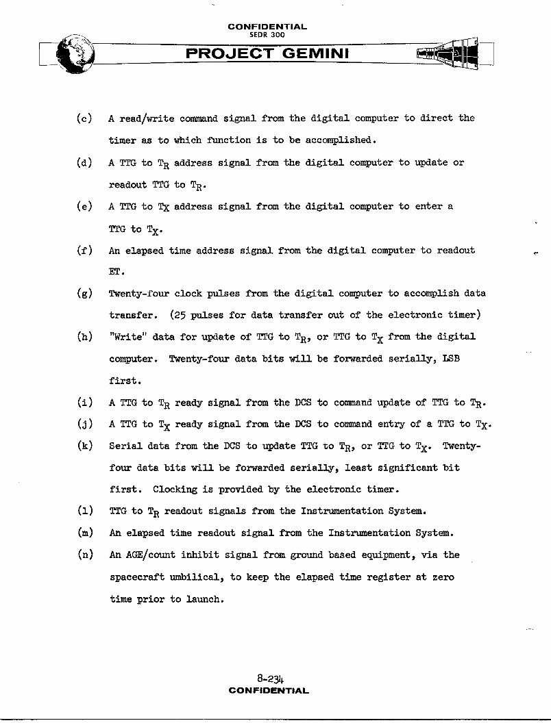
CONFIDENTIAL
PROJECT GEMINI
(c) A read/write command signal from the digital computer to direct the
timer as to which function is to be accomplished.
(d) A TTG to TR address signal from the digital computer to update or
readout TTG to TR.
(e) A TTG to TX address signal from the digital computer to enter a
to Tx.
(f) An elapsed time address signal from the digital computer to readout
ET.
(g) Twenty-four clock pulses from the digital computer to accomplish data
transfer. (25 pulses for data transfer out of the electronic timer)
(h) "Write" data for update of TTG to TR, or TTG to TX from the digital
computer. Twenty-four data bits will be forwarded serially, I_B
first.
(i) A TTG to TR ready signal from the DCS to command update of TTG to TR.
(J) A TTG to TX ready signal from the DCS to comm_nd entry of a TTG to Tx.
(k) Serial data from the DCS to update TTG to TR, or TTG to Tx. Twenty-
four data bits will be forwarded serially, least significant bit
first. Clocking is provided by the electronic timer.
(1) TTG to TR readout signals from the Instrumentation System.
(m) An elapsed time readout signal from the Instrumentation System.
(n) An AGE/count inhibit signal from ground based equipment, via the
spacecraft umbilical, to keep the elapsed time register at zero
time prior to launch.
8-23]I-CONFIDENTIAL
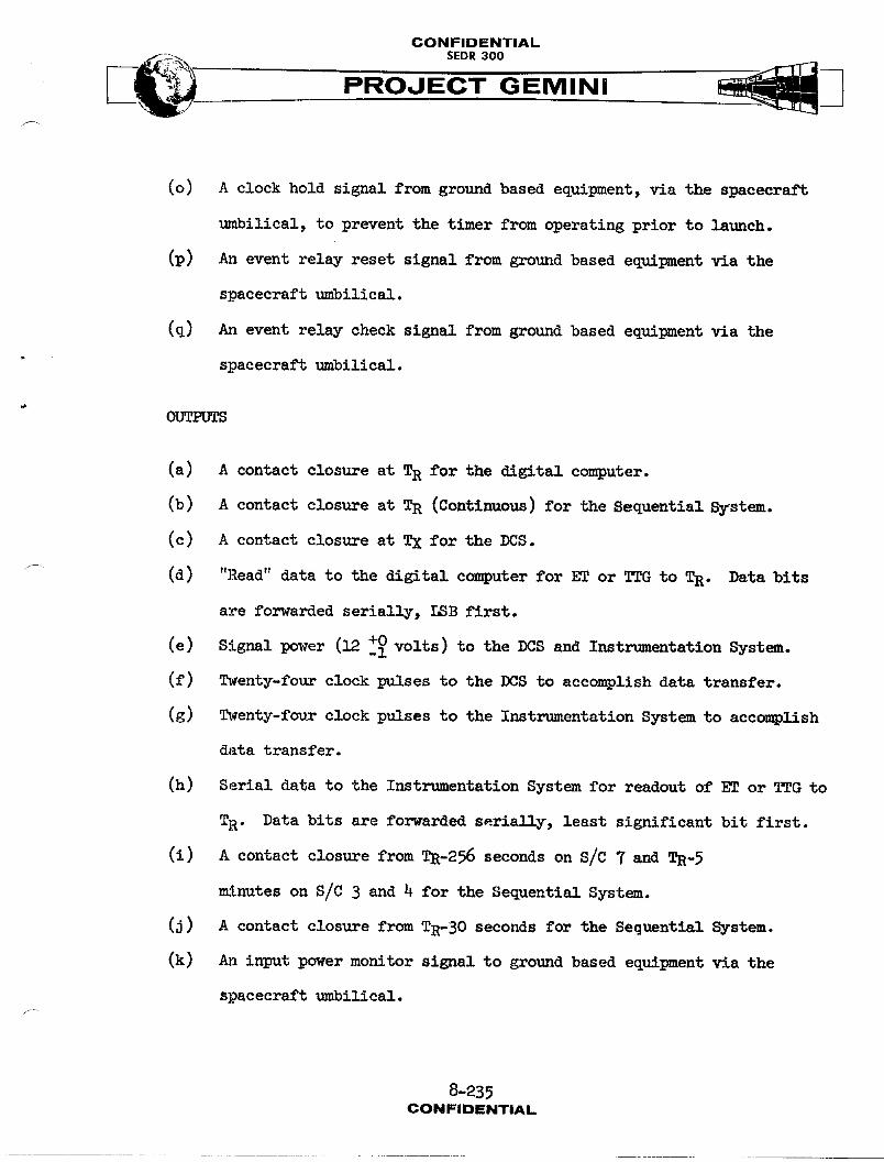
CONFIDENTIAL
PROJECT GEMINI
(o) A clock hold signal from ground based equipment, via the spacecraft
umbilical, to prevent the timer from operating prior to launch.
(p) An event relay reset signal from ground based equipment via the
spacecraft umbilical.
(q) An event relay check signal from ground based equipment via the
spacecraft umbilical.
(a) A contact closure at TR for the digital computer.
(b) A contact closure at TR (Continuous) for the Sequential System.
(c) A contact closure at TX for the DCS.
(d) "Read" data to the digital computer for ET or TTG to TR. Data bits
are forwarded serially, LSB first.
(e) Signal power (12 +i0 volts) to the DCS and Instrumentation System.
(f) Twenty-four clock pulses to the DCS to accomplish data transfer.
(g) Twenty-four clock pulses to the Instrumentation System to accomplish
data transfer.
(h) Serial data to the Instrumentation System for readout of ET or TTG to
TR. Data bits are forwarded serially, least significant bit first.
(i) A contact closure from TR-256 seconds on S/C 7 and TR-5
minutes on S/C 3 and 4 for the Sequential System.
(j) A contact closure from TR-30 seconds for the Sequential System.
(k) An input power monitor signal to ground based equipment via the
spacecraft 1,mbilical.
8-23_CONFIDENTIAL

CONFIDENTIAL
PROJECT GEMINI
TIME CORRELATION BUFFER
General
The Time Correlation Buffer (TCB), used on S/C 4 and 7, supplies the time corre-
lation signals for the bio-medical and voice tape recorders. Serial data and
data clock output from the electronic timer is applied to the TCB input. _
Serial data contains 24 elapsed time words, and extra elapsed time word and
a time to go to retrograde word. The TCB selects the extra elapsed time word
and modifies the word format to make it compatible with the tape recorder
frequency responses. Information to the recorder is updated once every 2.4
seconds and has the same resolution (1/8 second) as the electronic timer.
Construction
The dimensions of the TCB (Figure 8-62) are 2.77" X 3.75" X 3.80" and the weight
is approximately 3.0 pounds. The TCB contains magnetic shift registers, a lOO KC
astable multivibrator, a power supply and logic circuitry. One 19 pin connector
provides both input and output connections.
Operation
The operation of the TCB is dependent on signals from the Instrumentation System
and the electronic timer. In response to request pulses from the Instrumentation
System, the electronic timer provides elapsed time and time-to-go to retrograde
words to both the instrumentation system and the TCB. The elapsed time word is
supplied every 100 milliseconds. In addition, once every 2.4 seconds it pro-
vides an extra elapsed time word and lOO mi]_iseconds later it provides a time
to go to retrograde word.
8-236CONFIDENTIAL
CONFIDENTIALSEDR300
The TCB requires elapsed time information only; therefore, the time to go to
retrograde word is rejected. The tape recorders, due to their response times,
are not capable of recording time data every lO0 milliseconds and for this
reason, only the extra elapsed time word is accepted by the TCB. The remaining
24 elapsed time words and the time to go to retrograde word are rejected by
logic circuitry in the TCB. Rejection of unused words is based on their time
relationship to other words.
The TCB contains three 8-bit magnetic shift registers in which the 24 bit extra
elapsed time word is loaded once every 2.4 seconds. The TCB then shifts out
bits at the rate of one every lOOmilllseconds. The shift rate is based on
data clock pulses from the electronic timer. The first data clock pulse in as_
word causes the TCB to shift out one bit of the data and the other 23 data clock
pulses are disregarded.
Each bit that is shifted out of the shift register is stretched in time and
coded to make it compatible with tape recorder response times. The output to
the bio-medical recorder is one positive pulse for a binary "O" and two positive
pulses for a binary "l." The most significant bit has two additional pulses
to distinguish it from the other 23 bits in the word. Data is shifted out of
the TCB in a least significant bit first and most significant or marker bit
last.
The output to the voice tape recorder is the same basic format as for the
bio-medical recorders. However, to make it compatible with the higher fre-
_ quency response characteristics of the voice tape recorder, each output
pulse is chopped into two pulses, doubling the frequency.
8-237CONFIDENTIAL
CONFIDENTIAL
PROJECT GEMINI
All input and output signals are coupled through isolation transformers providing
complete DC isolation.
MISSION_ED TIME DIGITALCLOCK
The mission elapsed time digital clock (used on S/C 7) is capable of counting
time up to a maximum of 999 hours, 59minutes and 59 seconds. The time is
displayed on a decimal display indicator on the face of the unit. The seconds
tumbler of the display is further graduated in 0.2 second increments. Counting
may be started or stopped manually or by a remote signal. Prior to initiating
a counting operation, the indicator should be manually preset to the desired
starting time.
Construction
The dimensions of the digital clock are approximately 2 inches by 4 inches by
6 inches and its weight is approximately 2 pounds. On the face of the clock
there are two controls and a decimal display window. The unit contains four
electronic modules, a relay and a step servo motor. A gear train connects the
servo motor with the decimal display tumblers. An electrical connector is
provided at the rear of the unit for power and signal inputs.
Operatio n
Operation of the digital clock is dependent on timing pulses from the electronic
timer. The time base used for normal counting operations in the digital clock
is derived from the 8pps timing pulse output of the electronic timer. The
8 pps signal is buffered and used to establish the repetition rate of a step
servo motor. The step servo motor is coupled through a gear train'to display
tumblers. Additional counting rates are selectable for the purpose of setting
3-238CONFiDENTiAL
CONFIDENTIAL
__ SEDR 300
PROJECT GEMINI
the clock to a desired starting point.
Start/Stop Operation
Remote starting of the digital clock is accomplished by providing the 8 pps
timing pulses from the electronic timer. Before remote starting can be accom-
plished, the START/STOP switch must be in the START position and the DECR/INCR
sv_tch must be in the O position. Manual starting of the digital clock can be
accomplished (if timing pulses are available) by placing the START/STOP switch
in the START position. This energizes the start side of the start/stop relay.
The relay applies control and operating voltages to the counting circuitry,
allowing the counting operation to begin. Counting may be stopped by removing
the time base (8 pps) from the clock or by placing the START/STOP switch ini
the STOP position, removing voltage and disabling the circuitry.
Counting Operations
When the start/stop relays are actuated and operating voltage of plus 28
volts DC applied to the servo motor, a plus 12 volt DC enable signal is applied
to the normal count gate. This initiates the counting sequence. The electronic
timer provides an 8 pps timing signal which is buffered and supplied to the
sequential logic section.
Sequential logic section consists of four set-reset flip flops which provide
tho necessary sequences of output signals to cause the servomotor to step in
one direction or the other (Figure 8-69). As the counting process begins, three
of the flip flops are in the reset condition (reset output positive) and one is
.... in the set condition (set output positive). With receipt of the first timing
8-2_9CONFIDENTIAL
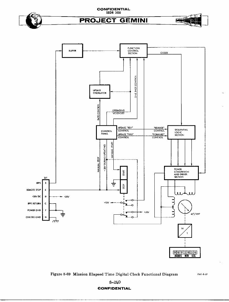
CONFIDENTIAL
PROJECT GEMINI
J J I _°NcT'°NBUFFER _ CONTROL
S[CTION CLOCK
1'I °8
OSCIIJ_TOR0
:1Z OPERATINGVO LTA G ES
I .... ICONTROL CONTROL CONTROL j SEQUENTIALLOGIC
PANEL UPDATE "FWD" "FORWARD" SECTIONCONTROL CONTROL
I _ ZI I
_ POWERI +I _ CONVERSIONi _ AND DRIVER
"',_L1 I SECTION
_sB. i _c-_
_O,E_O,E L 1 "4+28V DC D " +28V
8PPS RETURN C "_ +12V I
POWER G ND F _ I
_L. I _ _ +28V
- _CHASSIS GND _H II I'_'11 0"_
N,I
I
I
HOURSMIN SEC
Figure 8-69 Mission Elapsed Time Digital Clock Functional Diagram FM1-8-69
8-2/I0CONFIDENTIAL
CONFIDENTIAL
_. SEDR300
PROJECT GEMINI
pulse, the next flip flop switches to the set condition. The first one _]:_o
remains set, but the other two remain reset. Then, when another t_m_ngp_1_e
is received, the first flip flop resets, leaving only the second one set. The
sequence continues with alternate timing pulses setting one flip flop, then
resetting the preceding one. After the fourth flip flop has been set and the
third one subsequently reset, the first one is again switched to the set
condition and the sequence is started over again. In order to have the logic
section function properly, either a forward or reverse control signal must be
received from the start/stop relay. These are used as steering signsls for the
timing pulses which set and reset the flip flops. For counting up, the control
signals cause the flip flop operating sequence to be in one direction. When
counting down, they cause the sequence to reverse: flip flop number 4 is set
first, then number 3, etc., back through number 1. The output of the sequential
logic circuit is applied to the power conversion and driver section.
The power conversion and driver section converts the voltage-pulse outputs of
the logic section to current pulses which are used to drive the servomotor.
The driver section provides four separate channels, one for each input. Each
channel has a logic gate and a power driver. The logic gate permits the
logic section output to be sensed at ten selected times each second. The gate
senses only the occurrence of a positive signal which will allow the power
driver to conduct and send a pulse of current through one of the four servomotor
statorwindings.
8-241CONFIDENTIAL
CONFIDENTIAL_. SEDR300
The sequence of pulses from the driver section causes the servomotor to step
eight times each second and 45° each step. Figure 8-70 illustrates the step
positions relative to the sequence of operating pulses from the driver section.
If pulses were applied to each of the four servomotor windings, without overlap,
the unit would step 90° each repetition. It is this overlapping of signal
applications which causes it to step 45° at a time.
The display indicator is a rotating counter with wheels to display seconds,
tens of seconds, minutes, and tens of minutes, hours, tens of hours and hundreds
of hours. It is coupled to the servomotor through a gear train with a reduc-
tion ratio, from the servomotor, of lO:l. Therefore, as the servomotor rotates
360° (in one second), the indicator shaft turns 36° or 1/8 of a rotation.
Since the seconds wheel is directly coupled to the shaft and is calibrated from
zero to nine, a new decimal is displayed each second. As the seconds wheel
moves from nine to zero, the tens-of-seconds wheel moves to the one position.
The operations of the other wheels are similar.
Updating
The display may be returned to zero or updated to some other readout with the
use of the DECR-INCR rotary switch on the face of the timer. The rotary s_tch
must be in the O position in order to have the timer operate at a normal rate;
with the switch in one of the other positions, it counts at a different rate.
There are three rate selections, each, for the INCR and DECR (count-up and
count-down) updating modes. The positions on each side that are farthest from
the 0 position are utilized to make the timer count at 25 times its normal rate.
8-242CONFIDENTIAL
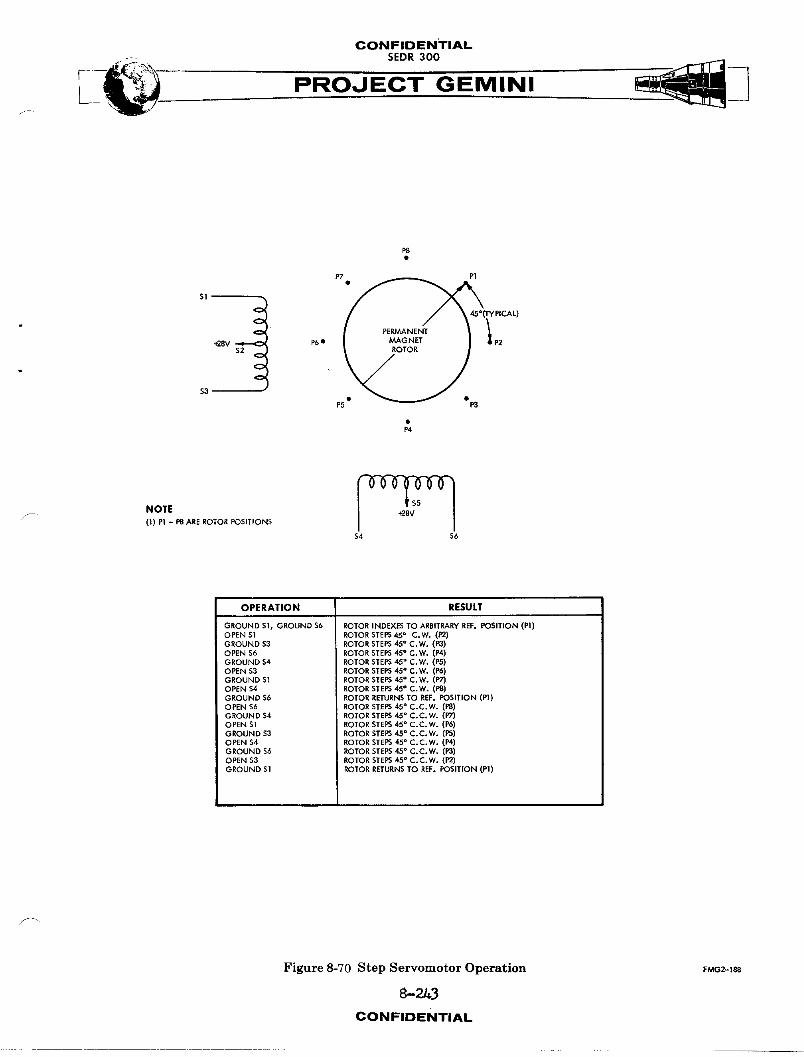
CONFIDENTIAL--. SEDR 300
P8
P7 • P|
• PERMANENT
+28V S2 P6" RoGTgR P2
NOTEF- (I) Pi - P8 ARE ROTOR POSITIONS
$4 S6
OPERATION RESULT
GROUND SI, GROUND $6 ROTOR INDEXES TO ARBITRARY R_. POSITION (PI)OPEN $I ROTOR STEPS45 ° C.W. (P2)GROUND $3 ROTOR STEPS45 ° C.W. (P3)OPEN S6 ROTOR STEPS45 Q C.W. (P4)GROUND $4 ROTOR STEPS45 ° C.W. (PS)OPEN $3 ROTOR STEPS45 ° C*W. (P6)GROUND $I ROTOR STEPS 45° C.W. (P-/)OPEN $4 ROTOR STEPS45 ° C.W. (PS)GROUND $6 ROTOR RETURNS TO REF, POSITION (PI)OPEN $6 ROTOR STEPS 45° C.C.W. (P8)GROUND $4 ROTOR STEPS 45° C.C.W. (PT)OPEN S] ROTOR STEPS 45° C.C.W. (P6)GROUND $3 ROTOR STEPS 45° C.C.W. (PS)OPEN $4 ROTOR STEPS 45° C.C.W. (P4)GROUND S6 ROTOR STEPS 45° C.C.W. (P3)OPEN S3 ROTOR STEPS 45_ C,C.W. (P2)GROUND $I ROTOR RETURNS TO REF. POSITION (PI)
Figure 8-70 Step Servomotor Operation FMG2-1_
8-2/,3CONFIDENTIAL
CONFIDENTIALSEDR 300
PROOECT GEMINI
The next closer positions are utilized to count at three times the normal rate.
The positions nearest the O position are used to count at a rate 0.3 times the
normal one. This position serves to more accurately place the indicator at
a desired readout.
Operationally, positioning the rotary switch in some position other than 0
causes the time base frequency from the electronic timer to be replaced in the
circuitry by an update oscillator. The frequency of the oscillator is estab-
lished by the position of the rotary switch. In the 25X positions, the frequency
is 400 cycles per second; in the 3Xposition, it is 48 cps; and in the 0.3X
positions, it is approximately 4.8 cycles per second. The accuracy of the
oscillator output is not critical since the ose_ISator functions only for up-
dating purposes.
EVENT TIMER
General
The event timer is capable of counting time, either up or do_m, to a maximum of
99minutes and 59 seconds on S/C 3 and 4 and to 59 minutes and 59 seconds on
S/C 7. The timer is capable of counting time down to zero from any preselected
time, up to the mA×imumlisted above.
8-2_t-CONFIDENTIAL
CONFIDENTIAL
.... PROJECT GEMINI
NOTE
When the event timer is counting down, it
will continue through zero if not manually
stopped. After counting through zero, the timer
" will begin counting down from 99 minutes
and 59 seconds on S/C 3 and 4 or 59 minutes
and 59 seconds on S/C 7.
The time is displayed on a decimal display indicator on the face of the unit.
The seconds tumbler of the display indicator is further graduated in 0.2
second increments. Counting, in either direction, may be started or stopped
either remotely or manually. Prior to starting a counting operation, the indi-
cator must be manually preset to the time from which it is desired to start
counting.
Construction
The dimensions of the event timer are approximately 2" x 4" x 6" and the weight
about two pounds. On the face of the timer, there are two toggle switches,
one rotary switch, and a decimal display window. (Refer to Figure 8-62. )
In addition to the panel-mounted controls, the unit contains four electronic
modules, two relays, a tuning fork resonator, and a step servomotor. A gear
train connects the servomotor with the decimal display tumblers. There is one
electrical connector on the back of the unit.
8-245CONFIDENTIAL
CONFIDENTIALSEDR300
O2eration
The operation of the event timer is independent of the electronic timer.
(Refer to Figure 8-71.) It provides its own time base which is used to control the
operation of the decimal display mechanism. The time base used for normal
counting operation is developed when the output of a tuning fork resonator is
connected to a series of toggle-type flip flops. The resulting signal estab-
lished the repetition rate of a step-type servomotor. The servomotor is coupled,
through a gear train, to the display tumblers. Additional counting rates may
be selected in order to rapidly reset the timer to zero or to some other
desired indication.
Start/Stop Operations
The remote and manual start/stop functions of the timer are accomplished in
almost exactly the same manner. The difference is only in the source of the
control signals. In order to initiate counting operations by either method,
it is necessary to first have the STOP-STBY toggle switch in either the STBY
or the center off position. (Refer to Figure 8-62.)
NOTE
When starting is accomplished with the
STOP-STBY switch in the center position,
a s,_11 inaccuracy is incurred. To pre-
vent any starting inaccuracies, place the
STOP-STBY switch in the STBY position
before starting the timer.
8-246CONFIDENTIAL
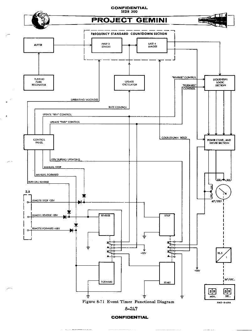
CONFIDENTIAL
.___ SEDR 300
PROJECT GEMINI
i .,ou,.c,_,..0..ocou.,oow,s,c,,o,iI IL__ 1
TUNING "REVERSE" CONll_OL SEQUENTIAL
FORK UPDATE LOGICRESONATOR OSCILLATOR SECTION
OPERATING VOLTAGES JRATE CONTROL
UPDATE "REV" CONTROLe
i UPDATE "FWD" CONTROL I_
I COUNTDOWN HOLDCONTROL -- POWE_ CONT. AND
PANEL DRIV_ SECTION
I
. MANUAL STOP I
÷28V DURING UPDATING J
MANUAL FORWARD
•MANUAL REVERSE
7 REMOTE STOP +28V _ 45
I 'I
JREMOT EFORWARD +28V JC ' I_1
"_I 'I ,
I
+I2V
,I+28V J
-- i _o/sEC.
T MIN. SEC.
Figure 8-71 Event Timer Functional Diagram FMI-8-69A
8-_/.7
CONFIDENTIAL

CONFIDENTIALSEDR 300
o M,N,Manual starting may then be accomplished by placing the UP-DN toggle s_tch in
either the UPor the DN position. This energizes one of the two coils of the
forward/reverse relay, also causing the start coil of the start/stop relay to
be energized. When these events take place, control and operating voltages
are supplied to the counting circuitry, thus allowing the operation to begin.
When starting is to be accomplished remotely, either a remote fo_ard or a remote
reverse signal is transmitted from the ground station to energize the fo_ard/
reverse relay. The countingprocess may be stopped upon receipt of a remote
step signal or by placing the STOP-STBY switch in the STOP position. Either
of these functions energizes the stop side of the start/stop relay, removing
critical operating voltages from the counting circuitry.
Countin_ Operations
Normal counting operations begin with the actuation of the forward/reverse
relay in either direction and the start/stop relay in the start direction.
Nhen the forward/reverse and the start/stop relays are actuated, an operating
voltage of +28 VDC is applied to the servomotor and a ground level inhibit signal
is removed from the toggle flip flops. Also, a +32 VDC control signal, denoting
either a forward or reverse counting process, is transmitted to the logic
circuitry preceding the servomotor. The remainder of the timer circuitry has
operatlngvoltages applied when the STOP/STBY switch is placed in STBY.
Nith the application of operating voltages, the tuning fork resonator emits an
AC signal of 1280 cycles per second. The signal is passed through a buffer to
condition it for use by the series of seven toggle flip flops in the frequency
standard countdown section. Since the output frequency of each flip flop is
8-248
CONFIDENTIAL

CONFIDENTIAL
PROJECT GEMINI
half that of its input, the final one in the series generates a signal of ten
pulses per second. The outputs of the countdo_m section are connected to the
sequential logic section and the power conversion and driver section.
Sequential logic section consists of four set-reset flip flops which provide
the necessary sequences of output signals to cause the servomotor to step in
one direction or the other (Figure 8-?1). As the counting process begins, three
of the flip flops are in the reset condition (reset output positive) and one
is in the set condition (set output positive). With receipt of the first timing
pulse, the next flip flop switches to the set condition. The first one also
remains set, but the other two remain reset. Then, when another timing pulse
is received, the first flip flop resets, leaving only the second one set.p-.
The sequence continues with alternate timing pulses setting one flip flop, then
resetting the preceding one. After the fourth flip flop has been set and the
third one subsequently reset, the first one is again switched to the set
condition and the sequence is started over again. In order to have the logic
section function properly, either a forward or reverse control signal must be
received from the forward/reverse relay. These are used as steering signals for
the timing pulses which set and reset the flip flops. For counting up, the control
signals cause the flip flop operating sequence to be in one direction. When
counting down, they cause the sequence to reverse: flip flop number 4 is set
first, then number 3, etc., back through number 1.
The power conversion and driver section converts the voltage-pulse outputs of
the logic section to current pulses which are used to drive the servomotor.
The driver section provides four separate channels, one for each input. Each
8-249CONFIDENTIAL
CONFIDENTIAL
PROJECT GEMINI:\
channel has a logic gate and a power driver. The logic gate permits the logic
section output to be sensed at ten selected times each second. The gate senses
only the occurrence of a positive signal which will allow the power driver to
conduct and send a pulse of current through one of the four servomotor stator
windings.
The sequence of pulses from the driver section causes the servomotor to step
ten times each second and 45° each step. Figure 8-69 illustrates the step
positions relative to the sequence of operating pulses from the driver section.
If pulses were applied to each of the four servomotor windings, without overlap,
the unit would step 90o each repetition. It is this overlapping of signal
applications which causes it to step 45° at a time.
The display indicator is a rotating counter with wheels to display seconds,
tens of seconds, minutes, and tens of minutes. It is coupled to the servomotor
through a gear train with a reduction ratio, from the servomotor, of 12.5;1.
Therefore, as the servomotor rotates 450° (in one second), the indicator shaft
turns 36° or i/i0 of a rotation. Since the seconds wheel is directly coupled
to the shaft and is calibrated from zero to nine, a new decimal is displayed
each second. As the seconds wheel moves from nine to zero, the tens-of-seconds
wheel moves to the one position. The operations of the other wheels are similar.
Updating
The display.my be returned to zero or updated to some other readout with the
use of the DECR-INCR rotary switch on the face of the timer. The rotary switch
must be in the O position in order to have the timer operate at a normal rate;
8-25oCONFIDENTIAL

CONFIDENTIAL
PROJECT GEMINI\
with the switch in one of the other positions, it counts at a different rate.
There are three rate selections, each, for the INCR and DECR (count-up and
count-down) updating modes. The positions on each side that are farthest from
the 0 position are utilized to make the timer count at 25 times its normal
rate. The next closer positions are utilized to count at four times the
normal rate. The positions nearest the 0 position are used to count at a rate
. 0.4 times the normal one. This position serves tom ore accurately place the
indicator at a desired readout.
Operationally, positioning the rotary switch in some position other than 0
causes the tuning fork resonator and the first three toggle flip flops to be
f replaced in the eircuitryby an update oscillator. The frequency of the
oscillator is established by the position of the rotary switch. In the 25X
positions, the frequency is 4,000 cycles per second; in the 4Xposition, it is
640 cps; and in the 0.4X positions, it is approximately 64 cycles per second.
The accuracy of the oscillator output is not critical since the oscillator func-
tions only for updating purposes.
ACCUTRON CLOCK
The Accutron clock (Figure 8-62), located on the command pilot's control panel,
is used on S/C 4 and 7. The clock is approximately 2 B/8 inches square and one
inch thick. The clock has a 24 hour dial withmajordlvisions on the half
hour. An hour hand, minute hand and a sweep secondhand are provided for a
precise indication of the time of day. The unit is completely self contained
and has no electrical interface with the spacecraft. The clock is capable of
operating continuously for approximately one year on the internal mercury
battery.
8-251CONFIDENTIAL
CONFIDENTIALSEDR 300
Operation
The Accutron clock is providedwith one control knob. The knob is used to stop,
set and start the timer as desired. To stop the timer, the control is depressed.
From the depressed position, the clock can be set to the desired time. The
cloek will start automatically when the control knob is released.
The Accutron clock is a highly accurate device with an error of less than
3 seconds per day. This high degree of accuracy is made possible by using a
tuning fork as the time standard, instead of the conventional balance wheel and
hair spring. The tuning fork is magnetically driven at a natural frequency of
360 cps. The t_m_ngfork frequency is adjustable, making precise calibration
of the clock possible. The vibrational motion of the tuning fork is converted
to rotational motionbya jeweled pawl and ratchet system. The rotary motion
is then appropriately geared to provide outputs of: one revolution per day, one
revolution per hour and one revolution per minute, for the clock hands.
MECHANICAL CLOCK
Construction
The mechanical clock (Figure 8-62) is approximately 2 1/4" x 2 1/4" x 3 1/4"
and weighs about one pound. The dial face is calibrated in increments of
0-24 and 0-60. The clock has two hands for the time of day portion and two
for the stolscatchportion. The controls for operating both portions of the clock
are located on the face of the unit.
8-252CONFIDENTIAL

CONFIDENTIAL
PROJECT' GEMINI
Operation
The clock is a mechanical device which is self-powered and requires no outside
inputs. The hand and dial-face clock displays Greenwich Mean Time ((_T) in
hours and minutes. A control on the face provides for_inding and setting
the unit. With the passing of each 24-hour period, the calendar date indicator
advances to the next consecutive number. The stopwatch portion of the clock
. can be started, stopped, and returned to zero at any time. Two settable markers
are provided on the minute dial to provide a time memory, permitting the clock
to serve as a short-term back-up timer.
r/
8-253/-254CONF_IDIENTIAL
CONFIDENTIAL
/
PROPULSION SYSTEMS
TABLE OF CONTENTS
TITLE PAGE
GENERAL INFORMATION . . . 8-25"/ORBITATTITUDEANDMA'_U_.P_bSYSTEM .......... 8-25'/SYSTEM DESCRIPTION i ........ 8-257
s SYSTEM OPERATION. • • • • • • • 8-261SYSTEM UNITS _ ___ ...... 8-263
_-ENTRYco_r_OLSYSTEM...... 8-28OSYSTEMDESCRIPTION......... 8-28OSYSTEM OPERATION .......... 8-284SYSTEM UNITS ........... 8-286
8-255
CONFIDENTIAL
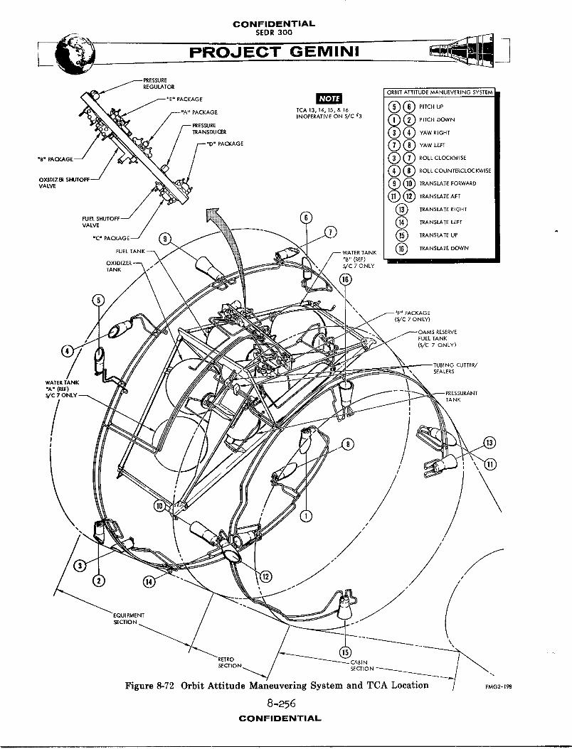
CONFIDENTIALSEDR 300
L_@ PROJECT GEMINIPRESSURE
REGULATOR. PACKAGE ORBIT ATTITUDE MANUEVERING SYSTEM JI
,NO._AT,VEO"S._'_ @®F,T¢.0ow.I
,,D-,ACKAo, @®_A_EF,I"B" PAOI(AGE @ @ ROLL CLOCKWISE I
®® _O_OU''0R_L_W'SEI(_) (_) TRA"_'.",EAE, I
WA,E_TA._®T_NS_,EOO_N I
I NOTE
"B" (REF)OXIDIZER-- S/C 7 ONLYTANK
(S/C 7 ONLY)
FUEL TANK
(S/C 7 ONLY)
CUTTER/SEALERS
WATER TANK
"A" (_:)
/
/ ,/
EgO.,,g_N, .-",
RETRO CAg_NSECTIOk
SECTION __ ".
Figure 8-72 Orbit Attitude Maneuvering System and TCA Location FMe2-_gS
8-256
CONFIDENTIAL
CONFIDENTIAL
PROJECT GEMINI
PROPULSION SYSTEM
GENERAL INFORMATION
The Gemini Spacecraft is provided with an attitude and maneuvering control
capability. (Figure 8-72). This control capability is used during the entire
spacecraft mission, from the time of launch vehicle separation until the re-
entry phase is completed. Spacecraft control is accomplished by two rocket engine
systems, the Orbit Attitude and Maneuvering System (OAMS) and the Re-entry
Control System (RCS).
The 0A_S controls the spacecraft attitude and provides maneuver capability from
the time of launch vehicle separation until the initiation of the retrograde
phase of the mission. The RCS provides attitude control for the re-entry module
during the re-entry phase of the mission. _ae OA_ and RCS respond to electri-
cal corm_andsfrom the Attitude Control Maneuvering Electronics (ACME) in the
automatic mode or from the crew in the manual mode.
ORBIT ATTITUDE AND MANEUVERING SYSTEM
SYST]_ DESCRIPTION
The Orbit Attitude Maneuvering System (OAN_) (Figure 8-72) is a fixed thrust,
cold gas pressurized, storable liquid, hypergolic bi-propellant, self contained
propulsion system, which is capable of operating in the environment outside the
earth's atmosphere. Maneuvering capability is obtained by firing thrust
chamber assemblies (TCA) singly or in groups. The thrust chamber assemblies
are mounted at vaious points about the adapter in locations consistent with the
modes of rotational or translation acceleration required.
8-257CONFIOENTIAL
CONI=ID_NTIAL
SEDR300
PROJECT GEMINI
The O_ provides a means of rotating the spacecraft about its three attitude
control axes (roll, pitch, and yaw) and translation control in six directions
(right, left, up, down, forward and aft). The combination of attitude and
translational maneuvering creates the capability of rendezvous and docking with
another space vehicle in orbit. Spacecraft 3 does not have the capability to
translate up, down, left or right.
The primary purpose of OAMS is spacecraft control in orbit. The OA_ is also
used, after firing of shaped charges, to separate the spacecraft from the launch
vehicle during a normal launch or in case of an abort which may occur late in
the launch phase. During initiation of retrograde sequence, tubing cutter/sealer
devices sever and seal the propellant feed lines from the equipment adapter.
A]] of the OA_4S(except six TCA's located in retro section) are separated from
the spacecraft with the equipment section of the adapter. Spacecraft control
functions are then assumed by the Re-entry Control System (RCS). OA_ control
units and tanks are mounted on a structural frame (module concept) in the equip-
ment section. The control units consist of forged and welded "packages". Each
package consists of several functioning components and filters. The delivery
of pressurant, fuel and oxidizer is accomplished by a uniquely brazed tubing
manifold system. The OAMS system is divided into three groups; pressurant group,
fuel/oxidizer group and thrust chamber assembly (TCA) group.
Pressurant Group
The pressurant group (Figure 8-73) consists of a pressurant tank, "A" package,
"E" package, "F" package on Spacecraft 7, pressure reg_1_tor, and "B" pacl_ge.
Inlet valves, ports and test ports are provided at accessible points to permit
servicing, venting, purging and testing. Filters are provided throughout the
8-258(;ONIFIDIENTIAL
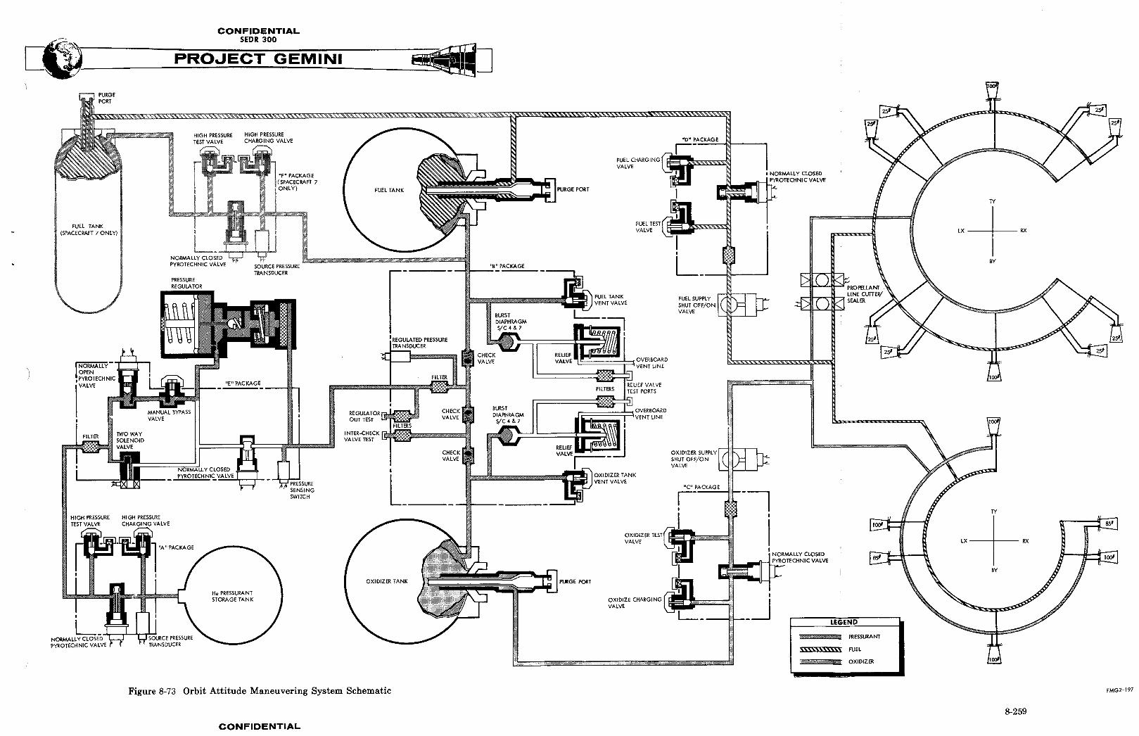
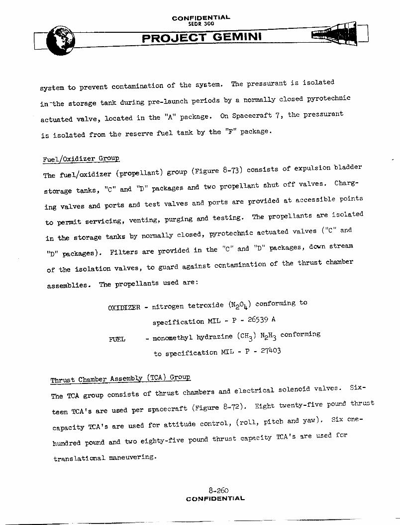
CONFIDENTIAL
PROJECT' GEMINI
system to prevent contsm_nation of the system. The pressurant is isolated
in-the storage tank during pre-launch periods by a normally closed pyrotechnic
actuated valve, located in the "A" package. On Spacecraft 7, the pressurant
is isolated from the reserve fuel tank by the "F" package.
Fuel/Oxldlzer Group
The fuel/oxidizer (propellant) group (Figure 8-73) consists of expulsion bladder
storage tanks, "C" and "D" packages and two propellant shut off valves. Charg-
ing valves and ports and test valves and ports are provided at accessible points
to permit servicing, venting, purging and testing. The propellants are isolated
in the storage tanks by normally closed, pyrotechnic actuated valves ('C" and
"D" packages). Filters are provided in the "C" and "D" packages, down stream
of the isolation valves, to guard against contamination of the thrust chamber
assemblies. The propellants used are:
OXIDIZER - nitrogen tetroxide (N204) conforming to
specification MIL - P - 26539 A
FUEL - monomethyl hydrazlne (CH3) N2H 3 conforming
to specification MIL - P - 27_0B
Thrust Chamber Assembl_ (TCA) Group
The TCA group consists of thrust chambers and electrical solenoid valves. Six-
teen TeA's are used per spacecraft (Figure 8-72). Eight twenty-five pound thrust
capacity TCA's are used for attitude control, (roll, pitch and yaw). Six one-
hundred pound and two eighty-five pound thrust capacity TCA's are used for
translational maneuvering.
8-260CONFIDENTIAL
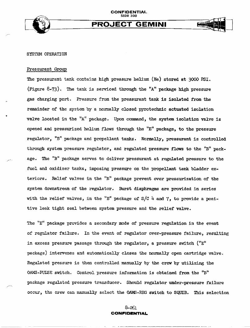
CONFIDENTIAL
:_ _..PROJECT GEMINI
SYST_ OPERATION
Pressurant Group
The pressurant tank contains high pressure helium (He) stored at 3000 PSI.
(Figure 8-73). The tank is serviced through the "A" package high pressure
gas charging port. Pressure from the pressurant tank is isolated from the
remainder of the system by a normally closed pyrotechnic actuated isolation
valve located in the "A" package. Upon command, the system isolation valve is
opened and pressurized helium flows through the "E" package, to the pressure
regulator, "B" package and propellant tanks. Normally, pressurant is controlled
through system pressure regulator, and regulated pressure flows to the "B" pack-
f age. The "B" package serves to deliver pressurant at regulated pressure to the
fuel and oxidizer tanks, imposing pressure on the propellant tank bladder ex-
teriors. Relief valves in the "B" package prevent over pressurization of the
system downstream of the regulator. Burst diaphragms are provided in series
with the relief valves, in the "B" package of S/C 4 and 7, to provide a posi-
tive leak tight seal between system pressure and the relief valve.
The "E" package provides a secondary mode of pressure regulation in the event
of regulator failure. In the event of regulator over-pressure failure, resulting
in excess pressure passage through the regulator, a pressure switch ("E"
package) intervenes and automatically closes the norms]ly open cartridge valve.
Regulated pressure is then controlled manually by the crew by utilizing the
OAN_-PUISE switch. Control pressure information is obtained from the "B"
package regulated pressure transducer. Should regulator under-pressure failure
occur, the crew can m_nually select the OA_3-REG switch to SQUIB. This selection
8-_61CONFIDENTIAL
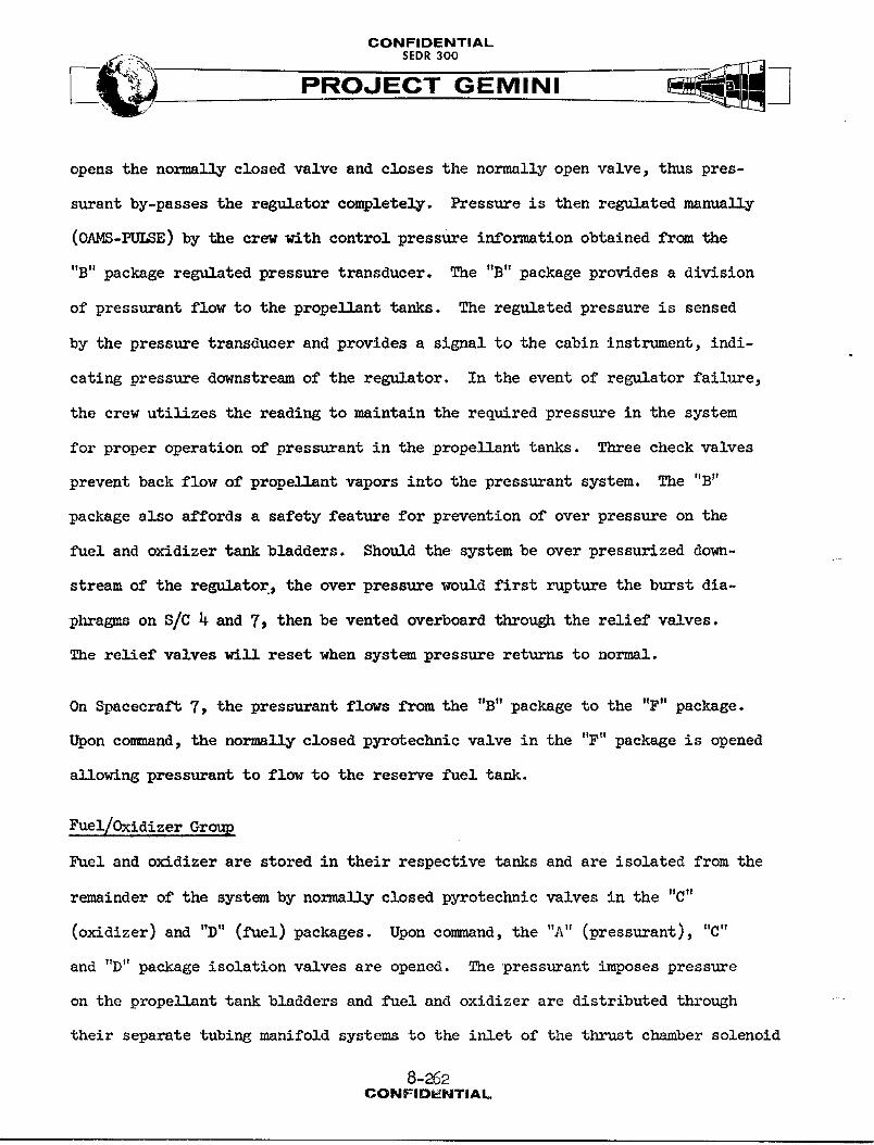
CONFIDENTIAL__ SEDR300
opens the normally closed valve and closes the normally open valve, thus pres-
surant by-passes the regt_lator completely. Pressure is then regulated manually
(OAMS-PULSE) by the crew with control pressure information obtained from the
"B" package regulated pressure transducer. The "B" package provides a division
of pressurant flow to the propellant tanks. The regulated pressure is sensed
by the pressure transducer and provides a signal to the cabin instrument, indi-
cating pressure downstream of the regulator. In the event of regulator failure,
the crew utilizes the reading to maintain the required pressure in the system
for proper operation of pressurant in the propellant tanks. Three check valves
prevent back flow of prop_11Ant vapors into the press_rant system. The "B"
package also affords a safety feature for prevention of over pressure on the
fuel and oxidizer tank bladders. Should the system be over pressurized down-
stream of the reg_lator_ the over pressure would first rupture the burst dia-
phragm2 on S/C _ and 7_ then be vented overboard through the relief valves.
The relief valves will reset when system pressure returns to normal.
On Spacecraft 7, the pressurant flows from the "B" package to the "F" package.
Upon co_m_and, the normally closed pyrotechnic valve in the "F" package is opened
allowing pressurant to flow to the reserve fuel tank.
Fuel/Oxidizer Group
Fuel and oxidizer are stored in their respective tanks and are isolated from the
remainder of the system by norms1]y closed pyrotec_mic valves in the "C"
(oxidizer) and "D" (fuel) packages. Upon command, the "A" (pressurant), "C"
and "D" package isolation valves are opened. The pressurant imposes pressure
on the propellant tank bladders and fuel and oxidizer are distributed through
their separate tubing manifold systems to the inlet of the thrust chamber solenoid
8-262CONFIDt_NTIAL

CONFIDENTIAL
_ SEDR 300
valves. Upon command on Spacecraft 7, the normally closed pyrotechnic valve
in the "F" package is opened to e11ow pressurant to impose pressure on the
reserve fuel tank bladder to distribute reserve fuel to the thrust chamber
solenoid valve. Two normally open electrlc-motor valves are located in the
propellant feed lines, upstream of the TCA's. In the event of fuel or oxidizer
leakage through the TCA solenoid valves, the motor operated valves can be closed
by the crew to prevent loss of prope11_nts. The valves can again be actuated
open by the crew, when required, to deliver propellants to TCA solenoids.
Thrust Chamber Assembl_ (TCA) Group
Upon comm_nd from the automatic or manual controls, signals are transmitted
through the attitude control maneuvering electronics (ACME) to selected TCA's
to open simultaneously the normally closed, quick-actlng fuel and oxidizer sole-
noid valves mounted on each TCA. In response to these commands, prope11_nts
are directed through small injector jets into the combustion chamber. The
controlled fuel and oxidizer impinge on one another, where they ignite hyper-
golieally to burn and create thrust.
SYST_ UNITS
Pressurant Storage Tank
The helium press_ant is stored in welded, titanium spherical tank. Tank
dimension is 16.20 inches outside diameter and has an intern_l volume of
1696.0 cubic inches. The helium gas is stored at 3000 PSI and held therein by
the "A" package _ormally closed pyrotechnic actuated valve. The pressurized
.... helium is used to expel the fuel and oxidizer from their respective tanks.
8-26_CONFIDEI_ITIAL

CONFIDENTIAL
s,oooPROJECT GEMINI
Temperature sensors are affixed to the pressurant tank and outlet line to
provide readings for the cabin instrument and telemetry.
"A" Package
The "A" package (Figure 8-74) consists of a source pressure transducer, isola-
tion wlve, two high pressure gas charging and test valves and filters. The
source pressure transducer monitors the pressurant tank pressure and transmits
an electric signal to the cabin propellant instrument and spacecraft telemetry
system. The normally closed pyrotechnic isolation valve is used to isolate
pressure from the r_Ainder of the system. The valve is pyrotechnic actuated
to the open position to activate the system for operation. Two dual seal,
high pressure gas charging valves and ports are provided, one on each side of
the isolation valve. The upstream valve is used for servicing, purging and
venting the pressurant tank, while the downstream valve is used to test downstream
components. The valve filters prevent contamination 8uring testing and ser-
vicing.
'!F"Package (Spacecraft 7 only)
The "F" package (Figure 8-74) consists of a source pressure transducer, isolation
valve, two high pressure gas charging and test valves and filters. The source
pressure transducer monitors the regulated pressure and transmits an electrical
signal to the cabin instrument and spacecraft telemetry indicating the amount
of regulated pressure for the reserve fuel tank. The normally closed pyro-
technic valve is used to isolate the pressurant from the reserve fuel tank.
The valve is pyrotechnic actuated to the open position to activate the reserve
fuel system for operation. Two dual seal, high pressure gas charging valves
8-264" CONFIDENTIAL
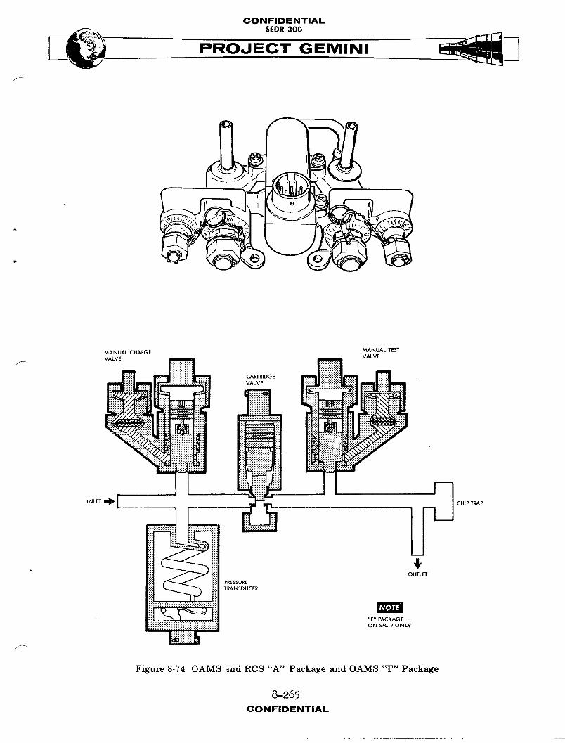
CONFIDENTIAL
PROJECT GEMINI
/
MANUAL CHARGE MANUAL TESTVALVE VALVE
PRESSUTRANSDUCER
!_:_:_iiii!iiiii!i•
NOTE
Figure 8-74 OAMS and RCS "A" Package and OAMS "F" Package
8-265
CONFIDENTIAL
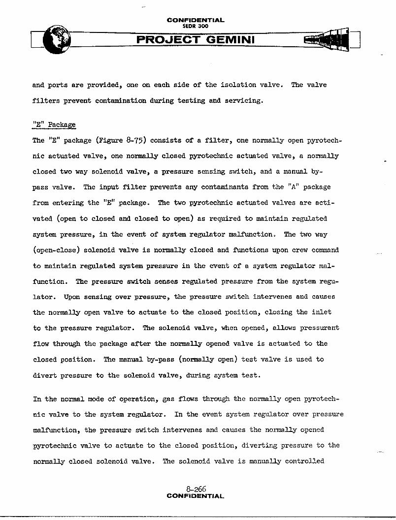
CONFIDENTIAL
PROJECT GEMINI
and ports are provided, one on each side of the isolation valve. The valve
filters prevent contamination during testing and servicing.
"E" Package
The "E" package (Figure 8-75) consists of a filter, one normally open pyrotech-
nic actuated valve, one norm_11y closed pyrotechnic actuated valve, a normally
closed two way solenoid valve, a pressure sensing switch, and a manual by-
pass valve. The input filter prevents any contnm_ nants from the "A" package
from entering the "E" package. The two pyrotechnic actuated valves are acti-
vated (open to closed and closed to open) as required to maintain regulated
system pressure, in the event of system regulator malfunction° The two way
(open-close) solenoid valve is normally closed and functions upon crew command
to maintain regulated system pressure in the event of a system regulator mal-
function. The pressure switch senses regulated pressure from the system regu-
lator. Upon sensing over pressure, the pressure switch intervenes and causes
the normally open valve to actuate to the closed position, closing the inlet
to the pressure regulator. The solenoid Valve, when opened, allows pressurant
flow through the package after the normally opened valve is actuated to the
closed position. The manual by-pass (normally open) test valve is used to
divert pressure to the solenoid valve, during system test.
In the normal mode of operation, gas flows through the normally open pyrotech-
nic valve to the system regulator. In the event system regulator over pressure
malfunction, the pressure switch intervenes and causes the normally opened
pyrotechnic Valve to actuate to the closed position, diverting pressure to the
normally closed solenoid Valve. The solenoid valve is manually controlled
8-266CONFIDENTIAL
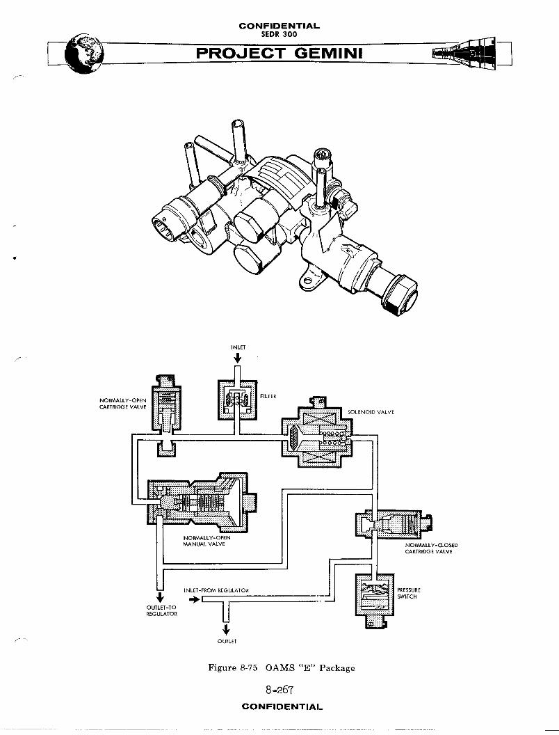
CONFIDENTIAL
PROJECT GEMINI
INLET
CARTRIDGE VALVE -- ALVE
NORMALLY-OPEN _ p
_A.OALVALV, _O_'-_O_EO
4,OUTLET
Figure 8-75 OAMS "E" Package
8-267
CONFIDENTIAL

CONFIDENTIALSEDR 300
(pulsed) by the crew to maintain regulated system pressure. In the event of
system regulator (under pressure) malfunction, the normally closed pyrotechnic
valve can be actuated to the open position. Simultaneously insured by the cir-
cuitry, the normally open valve is activated to the closed position. This pre-
vents by-pass of the solenoid valve. In this mode,a regulator by-pass cir-
cuit is provided and pressure is regulated by the crew.
Pressure Re6ulator '
The pressure regulator (Figure 8-76) is a conventional, mechanical-pnettmstic
type. The regulator functions to reduce the source pressure to regulated
system pressure. An inlet filter is provided to reduce any contaminants in
the gas to an acceptable level. An outlet line is provided from the regulated
pressure chamber to the pressure switch ("E" package) and activates the switch
in the event of an over pressure malfunction.
"B" Package
The "B" package (Figure 8-77) consists of filters, regulated pressure trans-
ducer, three check valves, two burst diaphragms, two relief valves, regulator
out test port, fuel tank vent valves inter-check valve test port, oxidizer
tank vent valve, and two relief valve test ports. The inlet filter reduces
any contaminants in the gas to an acceptable level. Test valve inlet filters
prevent any contnm_nants from entering the system. The regulated pressure
transducer monitors the regulated pressure and transmits an electric signal
to the cabin instrument and spacecraft telemetry indicating the amount of
regulated pressure. A single check valve prevents backflow of fuel vapors
into the gas system. Two check valves are provided on the oxidizer side to
8-268CONFIDENTIAL
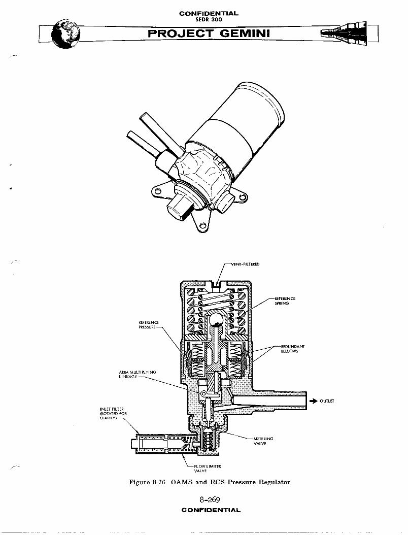
CONFIDENTIAL
___ SEDR300
PROJECT GEMINI
SPRING
i_ OUTLEE
(ROTATED FOR
"METERING
VALVE
Figure 8-76 OAMS and RCS Pressure Regulator
8 -269
CONFIDENTIAL
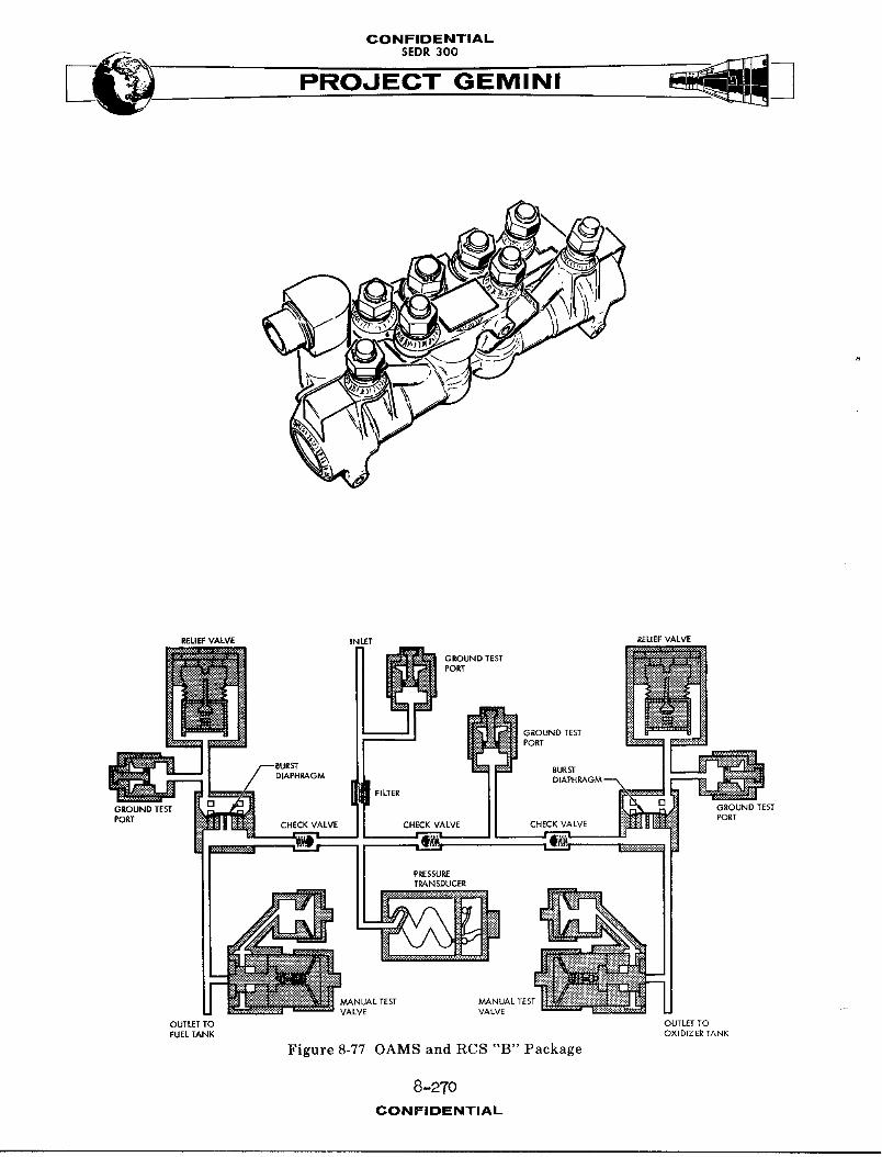
CONFIDENTIALSEDR300
REUEF VALVE INLET RELIEFVALVE
GROUND TESTPORT
PORT
OUTLET TO OUTLET TOFUEL TANK OXIDIZER TANK
Figure 8-77 OAMS and RCS "B" Package
8-2TOCONFIDENTIAL

CONFIDENTIAL
SEDR300
PRO,JI
to prevent backflow of oxidizer into the system. The burst diaphragms are
safety (over pressure) devices that rupture when re_1_ted pressure reaches the
design failure pressure, thus, prevents imposing excessive pressure on the
propellant bladders. The two relief valves are conventional, mechanical-pne_1,_tlc
type with pre-set opening pressure. In the event of burst diaphragm rupture,
the relief valve opens venting excess pressure overboard. The valve reseats
to the closed position when a safe pressure level is reached, thereby, pre-
vents venting the entire gas source. Manual valves and ports are provided to
vent, purge and test the regulated system.
Fuel Tank
F The fuel storage tank (Figure 8-78) is welded, titanium spherical tank which
contain an internal bladder and purge port. The tank dimension is 21.13 inches
in diameter, and has a fluid volume capacity of 5355.0 cubic inches. The tank
bladder is a triple layered Teflon, positive expulsion type. The helium pres-
surant is imposed on the exterior of the bladder to expel the fuel through the
"D" package to the thrust chamber solenoid valves. Purge ports are provided
to purge and vent the fuel tank. Temperature sensors are affixed to the input
pressurant line, fuel tank exterior and output llne to provide readings for
the cabin instrument and telemetry.
Reserve Fuel Tank (Spacecraft 7 only)
The fuel tank (Figure 8-86) is a welded, titanium cylindrical tank which
contains an internal bladder and purge port. The tank dimension is 5.10
inches outside diameter, 30.7 inches in length and has a fluid volume capacity
of 546.0 cubic inches. The helium pressurant is imposed on the exterior of
8-271CONFIDENTIAL
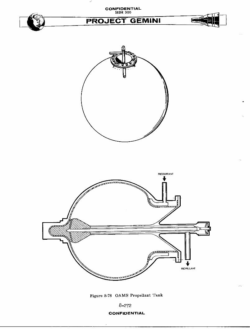
CONFIDENTIAL
PROJECT GEMINI
PRESSUREANT
4,
4,PROPELLANT
Figure 8-78 OAMS Propellant Tank
8-272
CONFIDENTIAL

@ONFIDIBN'rlAL
B
the bladder to expel fuel through the "D" package to the thrust c_m_er solenoid
valves.
Oxidizer Tank
The oxidizer tank (Figure 8-78)is welded, titanium spherical tank which con-
tain a bladder and purge port. The tank dimension is 21.12 inches in diameter,
and has a fluid volume capacity of 5355.0 cubic inches. The t_n_ bladder is
double layered Teflon, positive expulsion type. The helium pressurant is im-
posed on the exterior of the bladder to expel the oxidizer thro_ the "C"
package to the thrust c_mber solenoid valves. Purge ports are provided to
purge and vent the oxidizer tanks. Temperature sensors are affixed to the
input pressurant llne, oxidizer _nk exterior and output line to provide
readings for the cabin instrument and telemetry.
"C"and "D"jPacka@es
The "C" (oxidizer) and "D" (fuel) packages (Figure 8-79) are identical in func-
tion and are located downstream of the tank_ of their respective system. Each
package consists of a filter, isolation valve, propellant charging valve and
test valve. The filter is located at the outlet port to prevent cont_m_uants
frum entering the downstream system. The nor,mlly closed isolation valve is
used to isolate propellants from the remainder of the system during the pre-
launch waiting period. The isolation valve is pyrotechnic actuated to the
open position for system operation. The prope11_nt charging valve is located
upstream of the isolation valve and is used for servicing and venting the
system. The test valve is located downstream of the isolation valve and is
used to test the downstream system.
8-ZV3CONFIDENTIAL
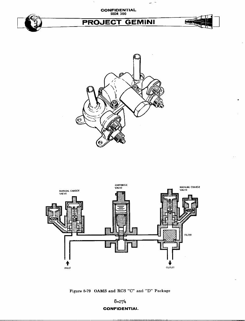
CONFIDENTIALSEDR300
CARTRIDGEVALVE MANUAL CHARGE
VALVE
, N N _ ELTE_
+ 1INLET OUTLET
Figure 8-79 OAMS and RCS "C" and "D" Package
8-2Tt_CONFIDENTIAL

CONFIDENTIAL
PROOECT GEMINI\.
Propellant Suppl_Shutgff/On Valves
Propellant supply shutoff/on valves (Figure 8-80) are provided for both the
oxidizer and fuel system and are located downstream of the "C" amd "D" pack-
ages in the system. The valves are motor operated, manual/electric controlled
type. The propellant valves serve as safeguards in the event of TCA leakage.
The valves are normally open, and are closed at the option of the crew to pre-
vent loss of propellants. The valve is thereafter reopened only when it is
necessary to actuate the TCA's for the purpose of spacecraft control.
Thrust Chamber Assembl_ (TCA) Group
Each TCA (Figure 8-81, 8-82 and 8-83) consists of two propellant solenoid
valves, an electric heater, injection system, calibrated orifices, combustion
chamber and an expansion nozzle. The propellant solenoid valves are quick act-
ing, normally closed, which open simultaneously upon application of an electric
signal. This action permits fuel and oxidizer flow to the injector system.
The injectors utilize precise jets to impinge fuel and oxidizer stresm_ on one
another for eontrolledmlxing and combustion. The calibrated orifices are fixed
devices used to control propellant flow. Hypergolic ignition occurs in the com-
bustion chamber° The combustion chamber and expansion nozzle is lined with
ablative materials and insulation to absorb and dissipate heat, and control
external wall temperature. TCA's are installed wlthin the adapter with the
nozzle exits terminating flush with the outer moldline and located at various
points about the adapter section suitable for the attitude and maneuvering
control required. Electric heaters are installed on the TCA oxidizer valves
to prevent the oxidizer from freezing.
8-275CONFIDENTIAL
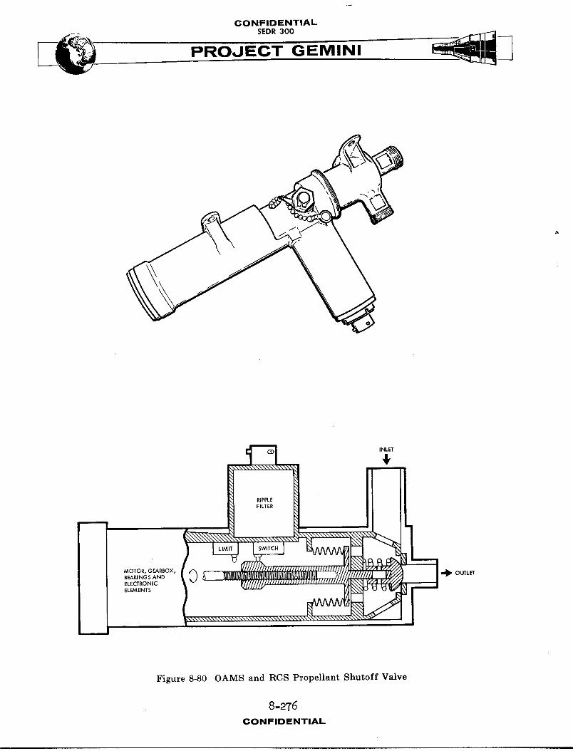
CONFIDENTIAL
PROJECT GEMINI
_ _\_\\\\_ INLET
4,
RIPPLE
F_LTER
Figure 8-80 OAMS and RCS Propellant Shutoff Valve
8-275CONFIDENTIAL
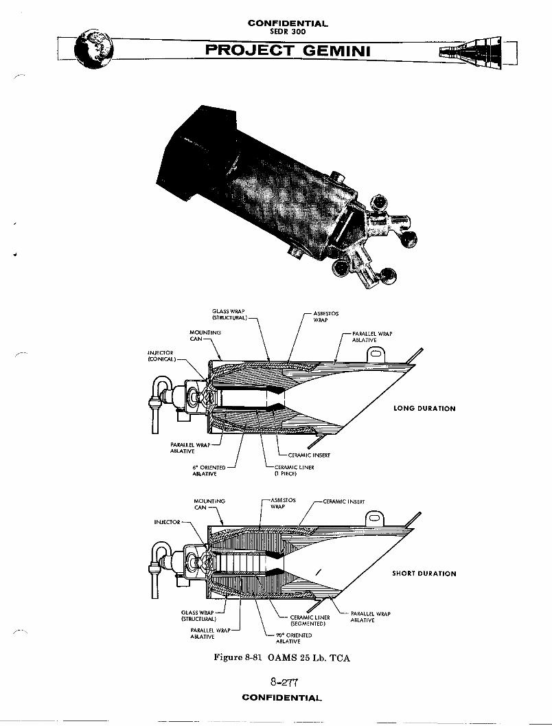
CONFIDENTIAL
PROJECT GEMINI
GLASS WRAP ASBESTOS
=.=,]]°°='_[_" .==_.-5 \ ../_.,1--,-- ',_:x°o:, A /
_..i.c....:.i..:.._:.;_i_/ . , r --_ DURATION
- ,_=.=wRA;-// l\ YABLATIVE (I PIECE)
MOUNTING
SHORTDURATION
PARALLEL WRAP
(STRUCTURAL) (SEGMENTED) ABLATIVE
,_" 90° ORIENTED
Figure 8-81 OAMS 25 Lb. TCA
8 -2"T7
CONFIDENTIAL
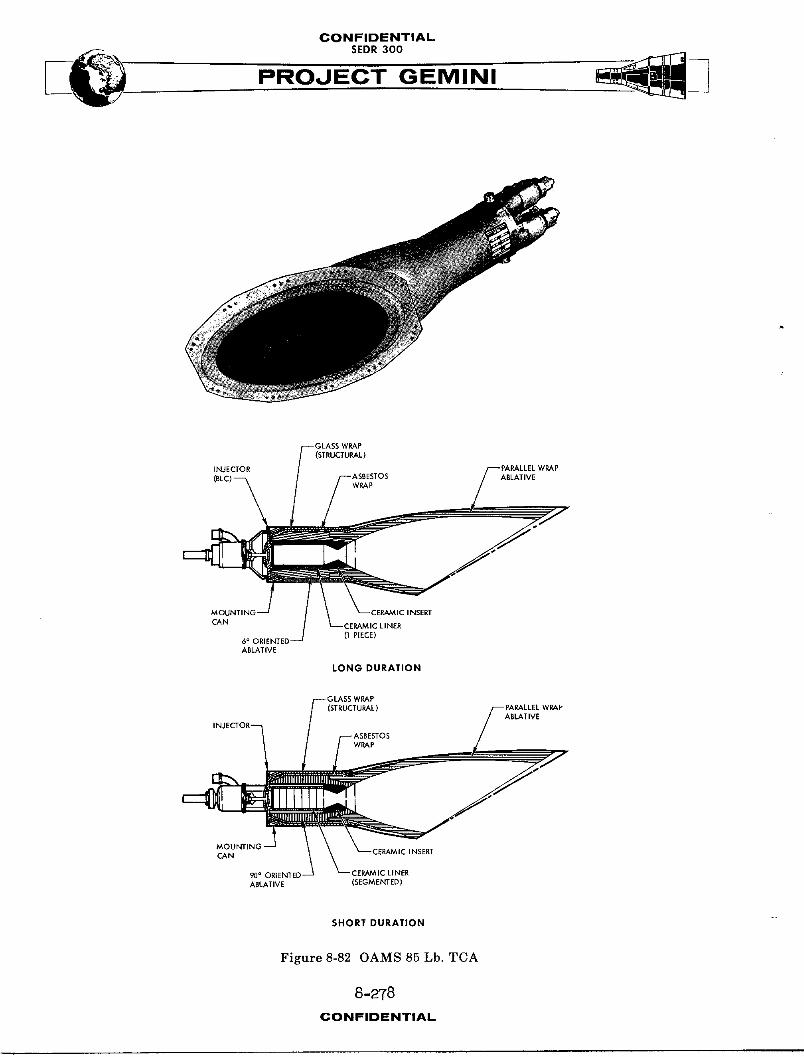
CONFIDENTIAL
PROJECT GEMINI
(STRUCTURAL)
INJECTORABLATIVE
WRAP
CAN :ERAM IC LINER(I PIECE)
6= ORIENTEDABLATIVE
LONG DURATION
(STRUCTURAL)ABLATIVE
WRAP
CAN INSERT
90° ORIENTED ERAMIC LINERABLATIVE (SEGMENTED)
SHORTDURATION
Figure 8-82 OAMS 85 Lb. TCA
8-278
CONFIDENTIAL
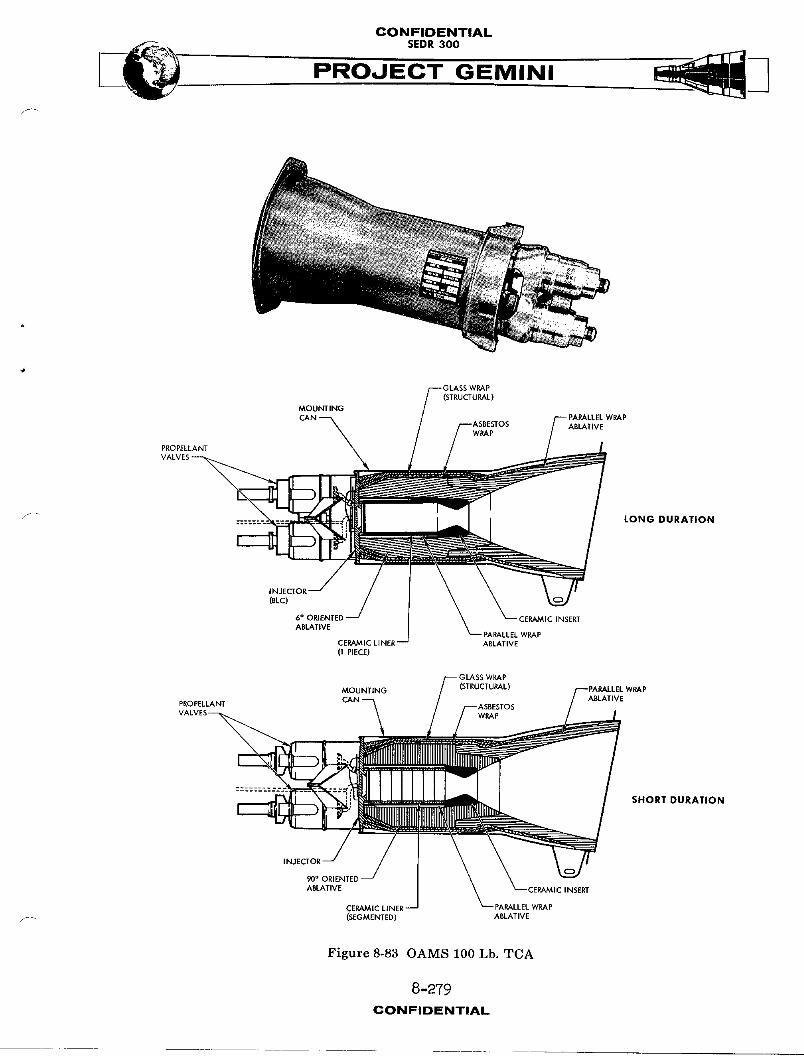
CONFIDENTIAL
PROJECT GEMINI
GLASS WRAP(STRUCTURAL)
MOUNTINGCAN PARALLEL WRAP
ASBESTOS ABLATIVEWRAP
PROPELLANT
VALVES __
PARALLEL WRApCERAMIC LINER-- ABLATIVE(! PIECE)
MOUNTING
SHORT DURATION
INJECTOR
90° ORIENTED
CERAMIC LINER
/_ (SEGMENTED) ABLATIVE
Figure 8-83 OAMS 100 Lb. TCA
8-279
CONFIDENTIAL
CONFIDINTIAL ')
SEDR300
PRMINI
Tubing Cutter/Sealer
The tubing cutter/sealer is a pyrotechnic actuated device and serves to posi-
tively seal and cut the propellant feed lines. Two such devices are provided
for each feed line and are located downstream of the propellant supply on/
off valve, one each in the retro and equipment section of the adapter. Prior
to retro fire, the equipment section is jettisoned. The devices are actuated
to permit separation of the feed lines crossing the parting line, and to con-
tain the propellants upon separation.
RE-ENTRY CONTROL SYST_4
SYSTEM DESCRIPTION
The Re-entry Control System (RCS) (Figure 8-84) is a fixed thrust, cold gas
pressurized, storable liquid, hypergolic bi-propellant, self contained pro-
pulsion system used to provide attitude control of the spacecraft during re-
entry.
NOTE
The RCS consists of two identical but entirely
separate and independent systems. The systems
may be operated individually or simultaneously.
One system will be described, all data is appli-
cable to either system.
The RCS system is capable of operating outside of the earth's atmosphere.
Attitude control (roll, pitch and yaw) is obtained by firing the TCA's in
groups. The TCA's are mounted at various points about the RCS section of the
-2 80CON FIDENTIAL
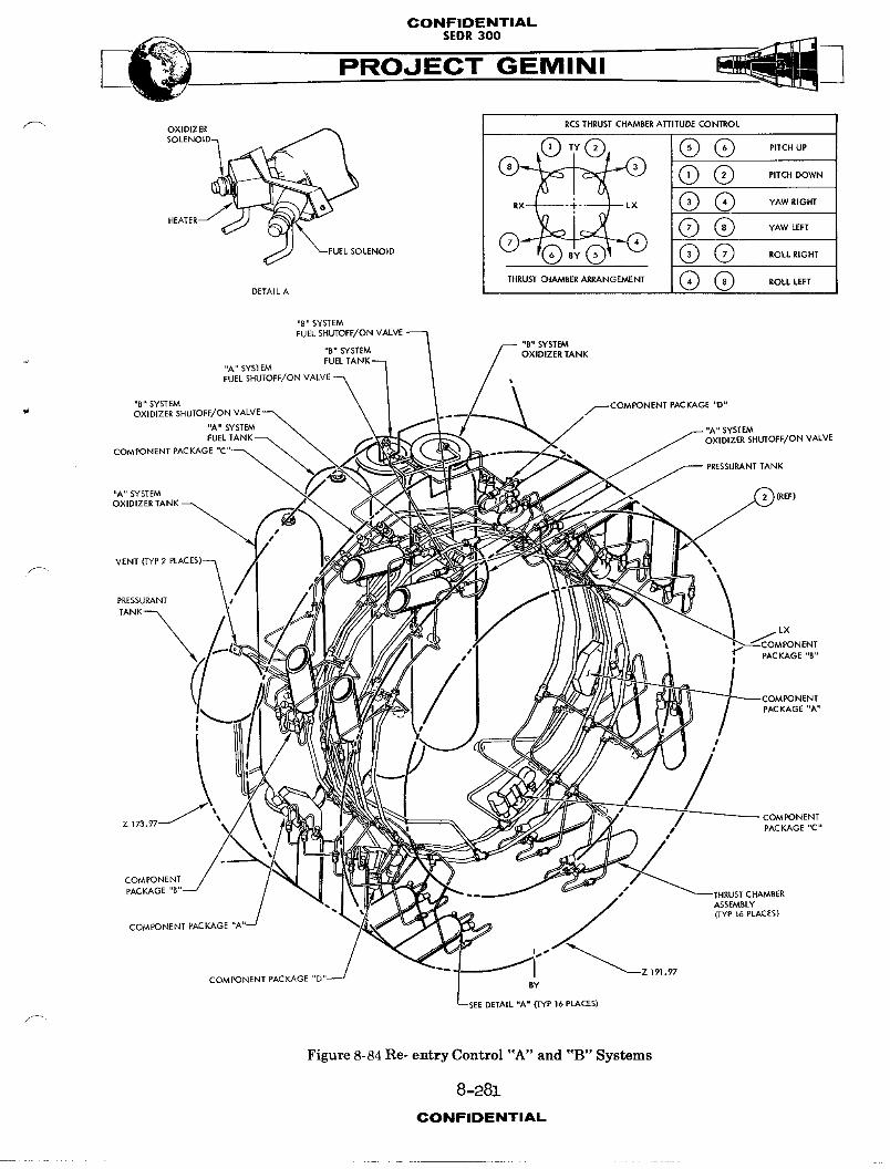
CONFIDENTIALSEDR 300
OXIDIZER RCSTHRUST CHAMBER A'nITUDE CONEROL
SOLENO,O_ ® (DTV@, @@ P,TCHUP
@@ ,AWR,G_'
EUE_SO_NO,O @(3 .OL_R,GH.THR__"R_NGE'_' @ @ RO_LLEFT
DETAIL A
"B" SYSTEMFUEL SHUTOFF/ON VALVE
"B" SYSTEM"B" SYSTEM OXIDIZER TANKFUEL
"A" SYSTEM
FUEL SHUTOFF/ON •
"B" SYSTEM _COMPONENT PACKAGE "D"/
"A" SYSTEM L" SYSTEMOXIDIZER SHUTOFF/ON VALVE
COMPONENT PACKAGE "C"_ '_
PRESSURANF TANK
"A" SYSTEM [(REF)
OXIDIZER TANKI
VENT (TYP 2 _.
PRESSUP-.ANT
TANK_
_NENT"11 PACKAGE "B"I
PONENT
PACKAGE"A"
I
; /Z 173.97 '% COMPONENT
f PACKAGE "C"
COMPONENT
PACKAGE "B s#' THRUST CHAMBER
ASSEMBLY
• (TYP 16 PLACES)
COMPONENT PACKAGE ",
Z 191.97COMPONENT PACKAGE "b
BY
(TYP 16 PLACES)
f_
Figure8-84Re- entryControl"A" and "B" Systems
8 -28].CONFIDENTIAL

CONFIDI[NTIAL
SEDR300
PROJECT GEMINI
spacecraft consistent with the modes of rotational control required. The entire
RCS, (tanks and control packages), with the exception of instrumentation, is
located in the HCS section of the spacecraft. Each package consists of several
functioning components and filters. The delivery of pressurants and propellants
is accomplished by a uniquely brazed tubing manifold system. The RCS system
is divided into three groups; pressurant group, the oxidizer/fuel (propellant)
group and the thrust chamber assembly (TCA) group.
Pressurant Group
The pressurant group (Figure 8-85) consists of a pressurant tank, "A" package,
pressure regulator and "B" package. Valves and test ports are provided at
accessible points to permit servicing, venting, purging and testing. Filters
are provided throughout the system to prevent system cont_m_natlon. The
pressurant is stored and isolated from the remainder of the system during pre-
launch periods by a normally closed pyrotechnic actuated valve, located in the
"A" package.
Fuel/Oxidizer Grou_
The fuel/oxidlzer (propellant) group (Figure 8-85) consists of exl_1aion
bladder storage tanks, "C" (oxidizer) and "D" (fuel) packages. Valves, ports
and test ports are provided at accessible areas to permit servicing, venting,
p_rging and testing. Filters are provided throughout the system to prevent
contamination. The prope!IAnts are isolated in the storage tanks from the
r_mAinder of the system by normally closed pyrotechnic actuated valves in the
"C" and "D" packages. Heaters are provided on the "C" package to maintain the
oxidizer at an operating temperature. The propellants used are:
8-282CONFIDENTIAL.
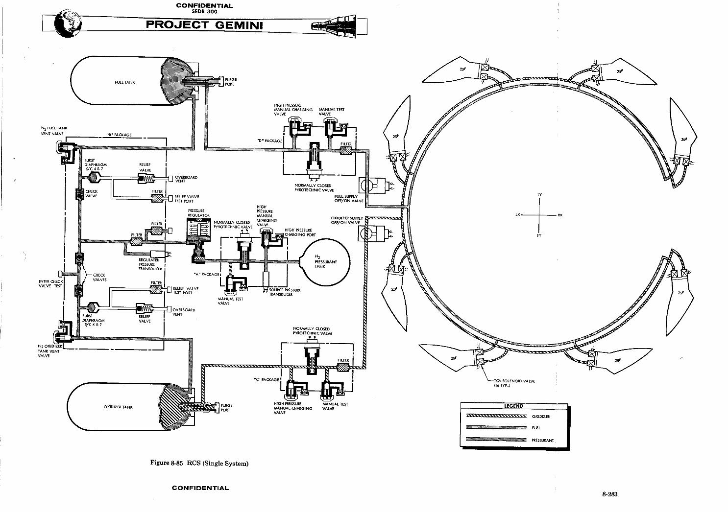
CONFIDISNTIAI-
SEDR300PROJECT GEMINI
Oxidizer - Nitrogen Tetroxide (N204) conforming to
Specification MIL - P - 26539A
FUEL - Monomethyl Hydrazine (CH3) N2H 3 conforming
to specification MIL - P - 27403
Thrust Chamber Assembl_ (TCA) Group
The TCA group (Figure 8-84) consists of eight twenty-five pound TCA's used for
attitude (roll, pitch and yaw) control of the re-entry module. Each TCA is
equipped with thrust chamber and electric controlled solenoid valves. Heaters
are provided on the oxidizer solenoid valves to maintain the oxidizer at an
operating temperature.
SYST224 OPERATION
Pressurant Group
(Figure 8-85) High pressure nitrogen (N2) (pressurant), is stored at 3000 PSI
in the pressurant tank. The tank is serviced throught the "A" package high pres-
sure gas charging port. Pressure from the pressurant tank is isolated from the
r_mAinder of the system, until ready for operation, by a normally closed pyro-
technic actuated valve located in the "A" package. Stored nitrogen pressure
is monitored and transmitted to the cabin instrumentation and spacecraft
telemetry system by the source pressure transducer located in the "A" package.
Upon comm_nd, the "A" package pyrotechnic actuated valve is opened (simultane-
ously, with prope11_ut "C" and "D" package pyrotechnic actuated valves) and
nitrogen flows to the pressure regulator and "B" package. The "B" package
provides a division of flow to the propellant tank._. The re_?1_ted pressure
is sensed by the regulated pressure transducer ("B" package) and provides a
8-284
CONFIDINTIAL

CONFIDENTIAL
SEDR300 -__-'_'r'_'_JPROJECT GEMINI
signal to the spacecraft telemetry system indicating pressure downstream of the
regulator. The check valves prevent backflow of propellant vapors into the
pressurant system. The "B" package also provides a safety feature to prevent
over pressure of the fuel and oxidizer tank bladders. Should the system be
over pressurized downstream of the regulator, the excess pressure is vented
over-board through the relief valves. On S/C 4 and 7, the over pressure would
first rupture the burst diaphragms, then be vented over-board through the
relief valves.
Fuel/Oxidizer Group
Fuel and oxidizer (propellants) are stored in their respective tanks, and are
serviced through the high pressure charging ports in the "C" and "D" packages.
The propellants are isolated from the remainder of the system, until ready for
operation, by the normally closed pyrotechnic valves in the "C" and "D" pack-
ages. Upon command, the "A" (pressurant), "C" (oxidizer) and "D" (fuel) pack-
age pyrotechnic actuated valves are opened and propellants are distributed
through their separate tubing manifold system to the thrust chamber inlet
solenoid valves.
Two normally open electric-motor valves are located in the propellant feed
lines, upstream of the TCA's. In the event of fuel or oxidizer leakage through
the TCA solenoid valves, the motor operated valves can be closed by the crew
to prevent loss of propellants. The valves can again be actuated open by the
crew, when required, to deliver propellants to the TCA solenoids.
Thrust Chamber.Assembly (TCA) Group
Upon co.mmnd from the automatic or manual controls, signals are transmitted
through the Attitude Control Maneuvers Electronics (ACME) to selected TCA's
8-285CONFIDENTIAL

CONPIOINTIAL
SEDR300PROJECT GEMINI
to open simultaneously, the normally closed, quick acting fuel and oxidizer
solenoid valves mounted on each TCA. In response to the signals, propellants
are directed through small injector jets into the combustion chamber. The
controlled fuel and oxidizer impinge on one another, where they ignite hyper-
golical_y to burn and create thrust.
SYSTEM UNITS
Pressurant Storage Tank
The nitrogen (N2) pressurant is stored in a welded, titanium spherical tank.
The tank dimension is 7.25 inches outside diameter and has an internal volume
of 185.0 cubic inches. Nitrogen gas is stored at BO00 PSI and held therein by
the "A" package pyrotechnic valve. This nitrogen under pressure is used to
expel the fuel and oxidizer from their respective tanks. Temperature sensors
are affixed to the pressurant outlet line to provide readings for the cabin
instrument and telemetry.
"A" Package
The "A" package (Figure 8-7_) consists of a source pressure transducer, isola-
tion valve, filters and two high pressure gas charging valves. The source
pressure transducer monitors the stored pressure and transmits and electric
signal to the cabin propellant instrument, indicating the pressure of the
stored gas. The normally closed isolation valve is used to isolate the pressure
from the remainder of the system.
The valve is pyrotechnically actuated to the open position to activate the
system for operation. Two dual seal, high pressure gas charging valves and ports
8-286CONFIDENTIAL

CONFIDENTIAL
are provided, one on each side of the isolation valve. The upstream valve is
used for servicing, venting and purging the pressurant tank, while the down-
stream valve is used to test downstream components. Filters are provided to
prevent contaminants from entering the system.
Pressure Regulator
The pressure regulator is a conventional, mechanical-pneumatic type. The
regulator functions to reduce the source pressure to regulated system pressure.
An inlet filter is provided to reduce any contaminants in the gas to an accep-
table level.
"B" Package
F The "B" package (Figure 8-77) consists of filters, regulated pressure trans-
ducer, three check valves, two burst diaphraEma, two relief valves, reg_;IAtor
output test port, fuel tank vent valve, oxidizer tank vent valve, inter-check
valve test port and two relief valve test ports. The inlet filter reduces any
contaminants in the gas to an acceptable level. Valve inlet filters prevent
contaminants from entering the system. The pressure transducer monitors the
regulated pressure and transmits an electrical signal to the spacecraft instru-
mentation system. A single check valve prevents backflow of fuel vapors into
the gas system. Two check valves are provided on the oxidizer side to prevent
backflow of oxidizer vapor into the gas system. The burst diaphragms are
safety devices that rupture when the regulated pressure reaches the design
failure pressure, thus, prevents imposing excessive pressure on the prope11_nt
bladders.
8-287CON IFIIDINTIAI,.

CONFIDENTIAL
PROJECT GEMINI
The two relief valves are conventional mechanical-pneumatic type with pre-set
opening pressure. In the event of burst diaphragm rupture, the relief valve
opens venting excess pressure overboard. The valve reseats to the closed posi-
tion when a safe level is reached, thereby, prevents venting the entire gas
source. Manual valves and ports are provided to vent, purge and test the
regulated system.
Fuel Tank
The fuel tank (Figure 8-86) is a welded, titanium cylindrical tank which contains
an internal bladder and purge port. The tank dimension is 5.10 inches outside
diameter, 30.7 inches in length and has a fluid volume capacity of 546.0 cubic
inches. The nitrogen pressurant is imposed on the exterior of the bladder to
expel fuel through the "D" package to the TCA solenoid valves. The purge port
is provided to purge and vent the fuel tank bladder. Temperature sensors are
affixed to the nitrogen input line and fuel output llne to transmit signals to
telemetry stations.
Oxidizer Tank
The oxidizer tank (Figure 8-86) is a welded, titanium cylindrical tank which
contains a bladder and purge port. The tank dimension is 5.10 inches outside
diameter, 25.2 inches in length and has a fluid volume capacity of 439.0 cubic
inches. The bladder is a double layered Teflon, positive expulsion type. The
nitrogen pressurant is imposed on the exterior of the bladder to expel the
oxidizer through the "C" package to the TCA solenoid valve. The purge port
is provided for purging and venting the oxidizer tank bladder. Temperature
sensors are affixed to the nitrogen input line and oxidizer output line to trans-
8-2_8CONFIDENTIAL

CONFIDENTIAL
PROOECT GEMINI
• _pEU.ANI
PRESSUREANT
Figure 8-86 RCS Propellant Tanks
8-289
CONFIDENTIAL

CONFIDENTIAL
SEDR300
PROJECT GEMINI
mit signals to telemetry stations.
"C" and "D" Packages
The "C" and "D" packages (Figure 8-79) are identical in function and are located
downstream of the tanks of their respective system. Each package consists of
fiJters, an isolation valve, propellant charging valve and test valve. The
filter located at outlet port reduces contaminants to an acceptable level.
The valve and port filters prevent contaminants from entering the downstream
system. The normally closed isolation valve is used to isolate propellants
from the remainder of the system during the pre-launch waiting period. The
isolation valve is pyrotechnic actuated to the open position for system opera-
tion. The propellant charging valve is located upstream of the isolation valve
and is used for servicing and venting the system. The test valve is located
downstream of the isolation valve and is used to test the downstream system.
Propellant Supply Shutoff/On Valves
Propellant supply shutoff/on valves (Figure 8-80) are provided for both the
oxidizer and fuel system, and are located downstream of the "C" and "D" pack-
ages in the system. The valves are motor operated, manual/electric controlled
type. The valves are normally open, and are closed at the option of the
crew to prevent loss of propellants. The valves are reopened only when the
TCA's are needed for spacecraft control.
Thrust Ch_ber Assembly (TCA) Group
Each TCA (Figure 8-87) consists of two prope71ant valves, injection system,
calibrated orifices, combustion chamber and expansion nozzle. The fuel and
8-290
CONFIDENTIAl.
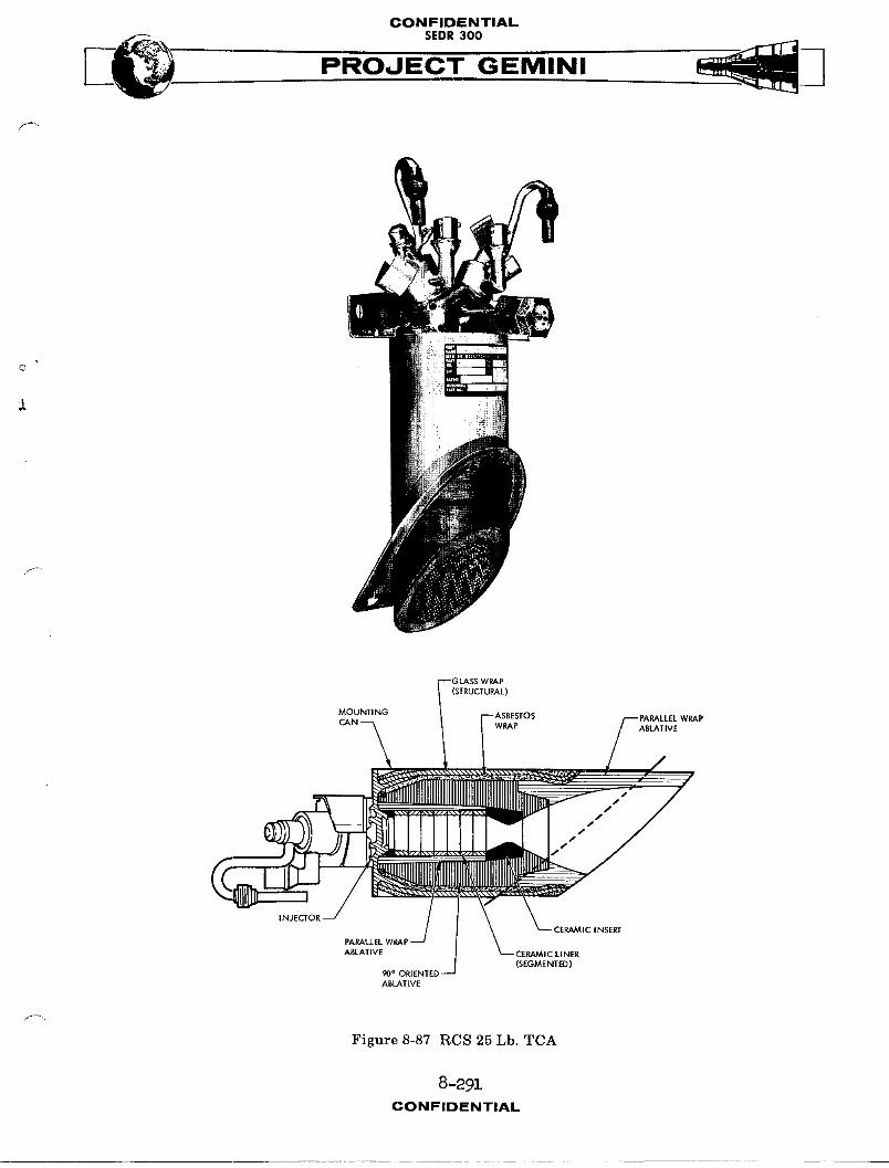
CONFIDENTIAL
___ $EDR300
PROJECT GEMINI
f--
(STRUCTURAL)
INJECTOR
(SEGMENTED)
ABLATIVE
Figure 8-87 RCS 25 Lb. TCA
8-291CONFIDENTIAL
CONFIDENTIAl--- SEDR300
PROJECT GEmiNI/
oxidizer solenoid valves are quick acting, normally closed, which open simul-
taneouslyupon application of an electric signal. The action permits fuel and ]/_
oxidizer flow into the injector system. The injectors use precise jets to impinge
fuel and oxidizer streams on one another for contro1_ed mixing and combustion. _ "
The calibrated orifices are fixed devices used to control propellant flow.
Kypergolic ignition occurs in the combustion chamber. The combustion chamber
and expansion nozzle is lined with ablative materials and insulation to absorb
and dissipate heat and control external wall t_mperature. TCA's are installed
within the RCS section mold llne, with the nozzles terminating flush with the
outer mold line. TCA's are located at flxedpoints in the RCS section in a
location suitable for attitude control. Electric heaters_ located on the oxidi-
zer valve, are used to prevent the oxidizer from freezing.
8-292CONFIOENTiAL