project final report - cordis.europa.eu no.248231 2012-12-21 file: d.6.1.1.final_report_final.doc...
TRANSCRIPT
MOSARIM No.248231 2012-12-21
File: D.6.1.1.final_report_final.doc 1/21
PROJECT FINAL REPORT
"Publishable summary"
Grant Agreement number: 248231
Project acronym: MOSARIM
Project title: MOre Safety for All by Radar Interference Mitigation
Funding Scheme: FP7-ICT-2009
Period covered: from 01. 01. 2010 to 31. 12. 2012
Name of the scientific representative of the project's co-ordinator1, Title and Organisation:
Dr.-Ing. Martin Kunert
Robert Bosch GmbH
Tel: +49 711 811 37468
Fax: +49 711 811 509004
E-mail: [email protected]
Project website2 address: www.mosarim.eu
1 Usually the contact person of the coordinator as specified in Art. 8.1. of the grant agreement 2 The home page of the website should contain the generic European flag and the FP7 logo which are available in electronic format at the Europa website (logo of the European flag: http://europa.eu/abc/symbols/emblem/index_en.htm ; logo of the 7th FP: http://ec.europa.eu/research/fp7/index_en.cfm?pg=logos). The area of activity of the project should also be mentioned.

MOSARIM No.248231 2012-12-21
File: D.6.1.1.final_report_final.doc 2/21
4.1 Final publishable summary report This is a comprehensive summary of results, conclusions and the socio-economic impacts of the project. The publishable report shall be formatted to be printed as a stand alone paper document. This report should address a wide audience, including the general public. Please ensure that it: Is of suitable quality to enable direct publication by the Commission.
Is comprehensive, and describes the work carried out to achieve the project's objectives; the main results, conclusions and their potential impact and use (including the socio-economic impact and the wider societal implications of the project). Please mention any target groups such as policy makers or civil society for whom the research could be relevant.
Includes where appropriate, diagrams or photographs and the project logo, illustrating and promoting the work of the project.
Provides the following information:
- List of all beneficiaries with the corresponding contact name and associated coordinates
- The address of the public Website of the Project as well as relevant contact details.

MOSARIM No.248231 2012-12-21
File: D.6.1.1.final_report_final.doc 3/21
Table of content Final publishable summary report .............................................................................................. 2 1. Introduction ......................................................................................................................... 4 2. The project activities ........................................................................................................... 6
2.1 Selection of important radar applications andfunctions .............................................. 6 2.2 Definition of relevant scenario definition .................................................................... 7 2.3 Market penetration study ............................................................................................. 7 2.4 The radar norm interferer device ................................................................................. 9 2.5 The radar simulation tool-chain ................................................................................. 10 2.6 The real world laboratory and road test ..................................................................... 12 2.7 The countermeasure and mitigation techniques ........................................................ 12 2.8 Determination of the interference hotspots ............................................................... 14 2.9 Safety level requirements .......................................................................................... 15
3. Guidelines, conclusions and outlook ................................................................................ 17 4. Acknowledgement ............................................................................................................ 20

MOSARIM No.248231 2012-12-21
File: D.6.1.1.final_report_final.doc 4/21
The EU-funded research project MOSARIM General overview and description of work carried out
Abstract: The European funding project MOSARIM (MOre Safety for All by Radar Interference Mitigation) started in January 2010 with the objective to investigate possible automotive radar interference mechanisms by both simulation and real-world road-tests. Appropriate countermeasure and mitigation techniques were investigated and assessed and general guidelines and recommendations developed. With a special norm interferer device that was also developed during project runtime the mitigation methods could be analyzed and verified in a reproducible and general manner. Project content and results were disseminated in two international public workshops and via the MOSARIM public webpage.
1. Introduction The MOSARIM project with Grant Agreement No. 248231 started officially on January 1st, 2010. The project duration is 36 month and the total project budget is 4.820.693 € with 2.897.173 € funding. The MOSARIM project’s main objectives are the investigation of mutual vehicular radar interference and the definition and elaboration of effective countermeasures and mitigation techniques. Automotive radar operational frequencies from 24 GHz to 79 GHz are covered by this project. The concept and overall objectives of the MOSARIM project are: 1. Assessment on actual radar interference potential and impact with of-the-shelf radar
sensors already available on the market. 2. Specification and implementation of a vehicular norm radar interferer. 3. Elaborate comprehensive and realistic simulation models regarding radar interference
on different levels. 4. Find common applicable interference countermeasures to reduce mutual radar
interference disturbance. 5. Generation of recommendations and guidelines for vehicular mutual radar interference
mitigation. The MOSARIM consortium consists of the following partners (see Figure 1):
Figure 1: The MOSARIM consortium with all 12 partners

MOSARIM No.248231 2012-12-21
File: D.6.1.1.final_report_final.doc 5/21
The main project activities and some of the important milestones are sketched in Figure 2.
Figure 2: The MOSARIM project timing
The MOSARIM project structure consists of six main work packages that are further broken down into specific project tasks. Each of the tasks is either finished with a deliverable or a milestone, respectively. Most of the delivered documents are public available on the MOSARIM webpage and only reports with sensor-individual, critical information content were left confidential. The work package structure is sketched in Figure 3.
Figure 3: The MOSARIM project structure (PERT diagram)

MOSARIM No.248231 2012-12-21
File: D.6.1.1.final_report_final.doc 6/21
2. The project activities Within the MOSARIM project different topics were addressed with different instruments, mainly simulation tools and real world test campaigns, complemented by studies and scenario definitions. While the project was mainly focused on mutual radar interference, i.e. the interference that occurs among the radars installed on vehicles on the road, in one task also the interference from incumbent radar systems, i.e. other non-automotive radars like e.g. police radar, fixed service links or traffic monitoring systems, was addressed. By jointly developing and improving the two main working axes the final project goals and targets could be reached. Figure 4 shows the working concept w.r.t. interaction and support between the two main research axes.
Modeling and simulation
Simple scenario Complex scenario
Input for validation Input for validation Mutual validation
Real world measurements
Test chamber Road scenarioComplexroad scenario
Norm interfererInterference mitigation techniques
Interference mitigation techniques
Figure 4: The MOSARIM project joint working principle
2.1 Selection of important radar applications and functions The application range of vehicular radar sensors is solely located in the domain of driver assistant systems. The already existing advanced driver assistance (ADAS) functions are depicted in Figure 5.
Figure 5: The current ADAS portfolio
The MOSARIM consortium selected the following 8 functions as the principal use cases for further evaluation in the real world test campaigns and the according simulations:
MOSARIM No.248231 2012-12-21
File: D.6.1.1.final_report_final.doc 7/21
Thank you for your kind attention !
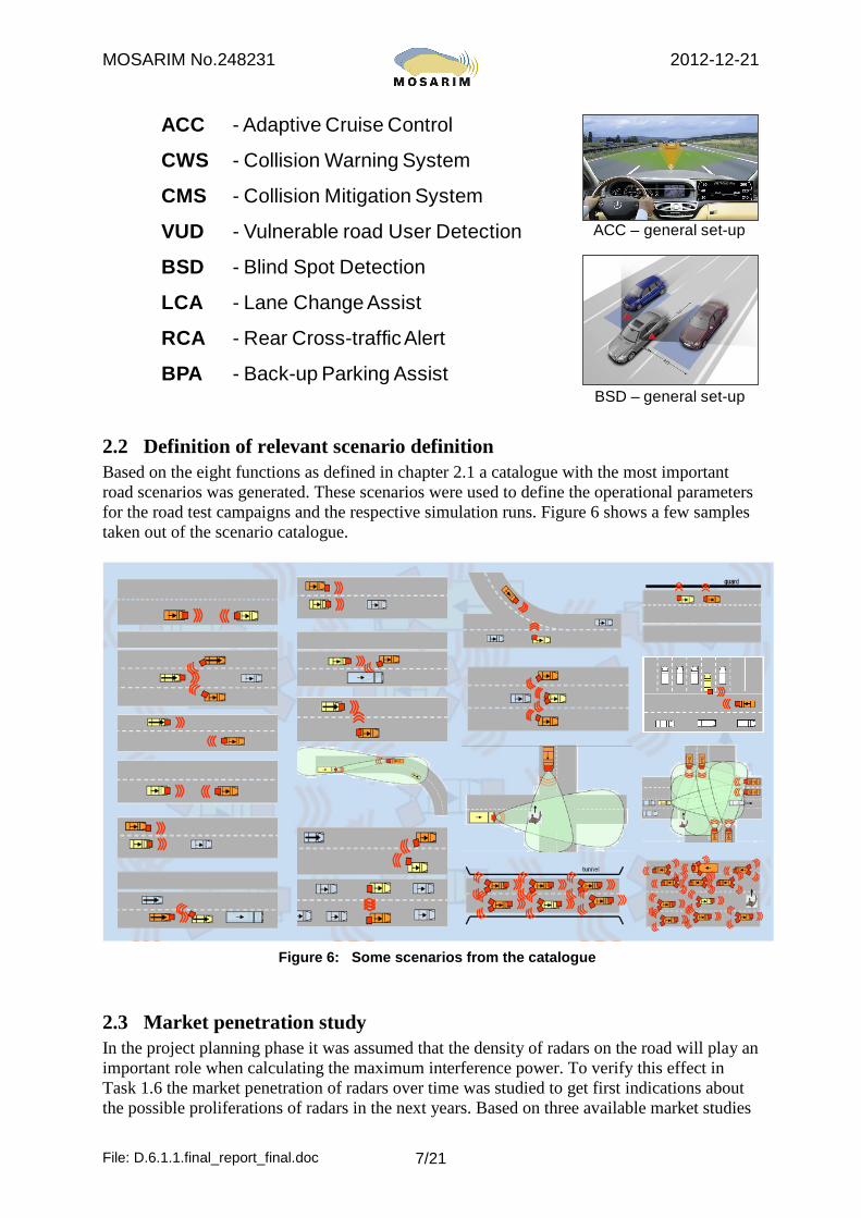
ACC - Adaptive Cruise Control
CWS - Collision Warning System
CMS - Collision Mitigation System
VUD - Vulnerable road User Detection
BSD - Blind Spot Detection
LCA - Lane Change Assist
RCA - Rear Cross-trafficAlert
BPA - Back-up Parking Assist
ACC – general set-up
BSD – general set-up
2.2 Definition of relevant scenario definition Based on the eight functions as defined in chapter 2.1 a catalogue with the most important road scenarios was generated. These scenarios were used to define the operational parameters for the road test campaigns and the respective simulation runs. Figure 6 shows a few samples taken out of the scenario catalogue.
Figure 6: Some scenarios from the catalogue
2.3 Market penetration study In the project planning phase it was assumed that the density of radars on the road will play an important role when calculating the maximum interference power. To verify this effect in Task 1.6 the market penetration of radars over time was studied to get first indications about the possible proliferations of radars in the next years. Based on three available market studies

MOSARIM No.248231 2012-12-21
File: D.6.1.1.final_report_final.doc 8/21
from Frost&Sullivan, ABI research and Techno Systems Research overall market penetration and percentage of newly radar equipped vehicles per year were forecasted until 2020, as shown in Figure 7. It has to be noted that the given numbers are not necessarily in agreement with the opinion of all the individual project participants.
Figure 7: Market penetration forecast of automotive radars
As by-product from the study, the approximate number of already sold radar and video devices in 2009 could be retrieved, as shown in Figure 8.
Source: Techno Systems Research Co. Ltd. , 2010
Overall summary
Sold radars in 2009:
2.390 Mio. pcs worldwide
Sold video cameras in 2009:
1.280 Mio. pcs worldwide
Figure 8: Automotive radar and video devices sold in 2009 (approximate values)

MOSARIM No.248231 2012-12-21
File: D.6.1.1.final_report_final.doc 9/21
2.4 The radar norm interferer device Based on a specification of the parameter sets of the commercially used modulation forms, which were compiled at the beginning of the project, two norm interferer prototypes were developed and used in the laboratory and road test campaigns as replacement of the earlier used individual radar interferer devices from the different radar manufacturers.
The basic idea to use a universal norm interferer device is to improve reliability and reproducibility of the interference measurements. Different to the case where specially prepared of-the-shelf radar sensors are used as interferers, the norm interferer prototype is capable to emulate all the existing radar sensor transmission waveforms in an exact timely and frequency-accurate manner. By software means the different modulation forms can be switched, making a direct comparison of the interference impact from different modulation waveforms first possible, as no equipment has to be changed and test-setup is untouched.
In Figure 9 the concept of the norm interferer prototype and the used frequency bands is shown. In Figure 10 the final prototype and the supported waveforms are presented.
PCNorm Interferer
USB-Bus
Frequency [GHz]21.65 23.6 24.05 26.65 76 81
powe
r
Portable, configurable and free running radar signal transmitting device for arbitrary interference and qualifying tests
Figure 9: Norm Interferer prototype with operational frequency ranges
76-81 GHz output21.65 – 26.65 GHz
output
Norm Interferer devicein operation
Norm Interferer device supported waveforms
Figure 10: Norm Interferer prototype and modulation waveforms

MOSARIM No.248231 2012-12-21
File: D.6.1.1.final_report_final.doc 10/21
From the first tests and measurements done with the two Norm Interferer (NI) prototypes, the benefit and advantages when using these two NIs became obvious. The results are better reproducible and measurement time is cut down significantly because no change in setup has to be done when changing from one sensor modulation scheme to another.
For qualifying tests according to a radar interference mitigation standard (that is not yet defined), the NIs can play a major role. Ideas for commercialization will be driven by the company InnoSenT, the project partner who has build-up the two prototypes.
2.5 The radar simulation tool-chain The development of a complete simulation tool-chain was the second main pillar of the MOSARIM project besides the practical assessment of radar interference impact and countermeasure effectiveness.
Based on already existing ray-tracing software for communication channel simulation, an automotive radar radio-location simulation tool with interference effect simulation was further developed by the Karlsruhe Institute of Technology (KIT). The coarse system modelling concept is sketched in Figure 11.
System Modelling
ScenarioRay-tracingsimulation
Channel modelling
Victim time domain signal
ADC & raw data processing
Analog signal processing
Interferer time domain signal (s)
Interferenceassessment(I/N, S/I, S/(I+N), power distribution in FFT)
Path informations- Path loss- Time delay- Doppler shift- Angles of incoming
and outgoing waves
TX TX
Known object positions/velocities
Comparison
Determination of system performance
Detected objectpositions/velocities
Can be simplified/replaced if modulation scheme interaction behavior is known
Figure 11: System modelling simulation basics and concept
The complete road scenario with both static and dynamic traffic scenario simulation is mapped into the simulation framework. The radar signal waveforms can be simulated down to the receiver input stage, where the IF-signals are generated based on the dynamic description of the real road scenario in a kind of storyboard.
The topology of the receiver model for a frequency modulating radar is exemplary shown in Figure 12. All the relevant and needed hardware components are represented by their equivalent building bloc models. During the three years project development time these models were more and more refined to represent the real behaviour of the radar input stage as good as possible.
In the Deliverable D2.7 a comparison between measured IF-signals from a real radar prototype and their simulated counterparts are provided. The deviation between reality and

MOSARIM No.248231 2012-12-21
File: D.6.1.1.final_report_final.doc 11/21
simulation stays below a few dBs even for high dynamic scenarios and all relevant details are well observable in the simulated signals.
Interferer 1
Interferer n
Figure 12: Typical topology of frequency modulating automotive radar model
By using the superposition principle the interference from single or multiple interferers can be induced in the wave propagation module.
In Figure 13 the building blocks used in the simulation tool-chain and some simulated results are shown. By varying the influencing parameters in the simulation the most meaningful real world tests could be found with design to experiment (DtE) methods.
Ray-tracing(channel modelling)
Multiple reflections(modified Fresnel)
Multiple diffractions(unifrom geom. theory)
Diffuse scattering(distributed Lambertian)
Interference over receiver noise simulation of a radar speed meter
Radar cross section of a passenger car and a pedestrian
Figure 13: Simulation tool-chain – wave propagation concepts and some simulation results

MOSARIM No.248231 2012-12-21
File: D.6.1.1.final_report_final.doc 12/21
2.6 The real world laboratory and road test Another major share of the MOSARIM project was devoted to the real world test campaigns that took place in different laboratories and on open air test sites.
In Figure 14, a coarse overview of all the test campaigns conducted is presented.
Devices under test
Laboratory
Test tracks
Complex environment
Figure 14: Real world test campaigns overview
Laboratory tests were conducted at Telefication in Zevenaar, The Netherlands, at KIT in Karlsruhe, Germany, and at JRC in Ispra, Italy. Road tests took place on Malmsheim and Griesheim airports in Germany, at Utrecht tunnel in The Netherlands and at a parking garage in Sindelfingen, Germany. Going into more detail for each of this measurement campaigns would go far beyond the scope of this report. Please refer to the relevant documents (e.g. Deliverable 4.5) and further informations that are available on the MOSARIM webpage.
2.7 The countermeasure and mitigation techniques Within the MOSARIM project the radar interference countermeasures were classified in six different domains, as sketched in Figure 15.
Polarization Time Frequency Coding Space Strategic
Figure 15: The six interference countermeasure domains

MOSARIM No.248231 2012-12-21
File: D.6.1.1.final_report_final.doc 13/21
In Figure 16 four examples of countermeasure techniques are demonstrated.
Figure 16: Examples of countermeasure techniques
From the more than 20 mitigation techniques studied and investigated of the six different domains, the MOSARIM consortium selected 9 most promising ones for an extensive further analysis or implementation in the respective radar sensors. The ranking result from Deliverable D3.2 is listed in Figure 17.
Ref. Title Total ranking from D3.2
Selection Status
T3.1 CFAR (constant false alarm rate) for interference mitigation 470
Selected techniques
for MOSARIM
T6.5 Detect interference and change transmit frequency range of chirps 463
T2.1 Using pauses of random length between chirps or pulses 460
T3.4 Application of driving direction specific pre-defined frequency band separation 437
T6.2 Detect interference and repair Rx results (Time domain) 433
T2.2 Using random sequence of chirp types (Up-chirp, Down-chirp, CW-Chirp) 432
T5.4 Digital Beam Forming 425
T6.4 Detect interference and change timing of transmit chirp or pulses 423
T1.2 Specific polarization following the Radar location (frontal, rear, side) 421
Figure 17: Ranking list of mitigation techniques

MOSARIM No.248231 2012-12-21
File: D.6.1.1.final_report_final.doc 14/21
The in-depth analysis of the nine selected countermeasures provided the following results, as listed in Figure 18.
Countermeasures Interference mitigation margin in dB Comment
T3.1CFAR (constant false alarm rate) for interference mitigation
ca. 10 - 20 dB
It can be used for all kind of functions without any constraints
CFAR performance slightly influence by number of targets
T6.5Detect interference and change transmit frequency range of chirps
up to infinity dB
Infinite mitigation margin can be obtained for 2 radars, but will be reduced if many interferers are present and band overlapping occurs.
Efficiency depends on the occupied bandwidth and the bandwidth available
T2.1Using pauses of random length between chirps or pulses
only a few dBsuppression of ghost targets and results in increase of noise floor. Typically measurement to pause ratio is maximum 50% => on average 3 dB mitigation margin
T3.4Application of driving direction specific pre-defined frequency band separation
up to infinity dB for same driving direction, but no
mitigation margin for crossing traffic
This needs worldwide coordination to become effective. For crossing traffic a special measure has to be found.
T6.2Detect interference and repair Rx results (Time domain)
up to ca. 20 dB possible The influence of fast or slow crossing FM chirps still needs further investigation on mitigation margin impact
Figure 18: Ranking list of mitigation techniques
From this list it can be concluded that the achievable mitigation margin is typically between a few dB up to infinity, i.e. complete interference suppression.
2.8 Determination of the interference hotspots During conducting real world test campaigns the knowledge and sensitivity w.r.t. meaningful test scenario setups was steadily improved. While for the first test scenarios the parameter space was rather large and the complete possible measurement range was scanned independent whether interference impact was present or not, for the later conducted tests, the measurement setup was already chosen in such a way that only the “hot-spot” locations with highest interference risk were in the scope.
T2.2
Using random sequence of chirp types (Up-chirp, Down-chirp, CW-Chirp)
Only a few dB
Suppression of ghost targets and results in increase of noise floor.
Only limited mitigation margin capability if done in the same frequency range
T5.4 Digital Beam Forming Only a few dB Mitigation effect depends on beamwidth (space domain)
T6.4Detect interference and change timing of transmit chirp or pulses
a large number of dBs is expected
With good timing and arrangement of FM ramps high margin can be reached.
A prerequisite is that all radars use same ramp duration to make synchronisation without ramp crossing possible
T1.2Specific polarisation following the Radar location (frontal, rear, side)
typically ca. 15 dB for co- to cross-polarization (linear)
This is already partially used for ACC radars that have 45 degree slant polarization (reduced interference from oncoming radars by 15 dB)
Note for cells marked in orange: Not tested within MOSARIM / margin is only estimated

MOSARIM No.248231 2012-12-21
File: D.6.1.1.final_report_final.doc 15/21
For the 8 applications under investigation the zones of highest interference differed and were distributed all around the vehicle, as shown in Figure 19.
Vulnerable road user detection (VUD)
Collision mitigation system(CMS)
Adaptive cruise control system(ACC)
Collision warning system(CWS)
Assisted parking systems(APS)
Blind spot monitoring(BSM)
Lane change assist(LCA)
Rear cross traffic alert(RCA)
Figure 19: Zones with highest interference for the selected 8 radar functions
It turned out that the mitigation techniques are fully independent from the different automotive functions, i.e. each mitigation technique can be applied to any of the automotive applications. On the contrary, as seen in Figure 19, this is not the case for the interference hot-spot zones.
2.9 Safety level requirements Already in the first project year the topic of safety level requirement was tackled. The subject of automotive safety integrity level (ASIL) becomes more and more important when going
MOSARIM No.248231 2012-12-21
File: D.6.1.1.final_report_final.doc 16/21
from applications with lower safety requirements, i.e. comfort oriented and warning functions to applications with higher safety requirements, i.e. safety critical functions that actively control vehicle actuators or even drive a car fully autonomous.
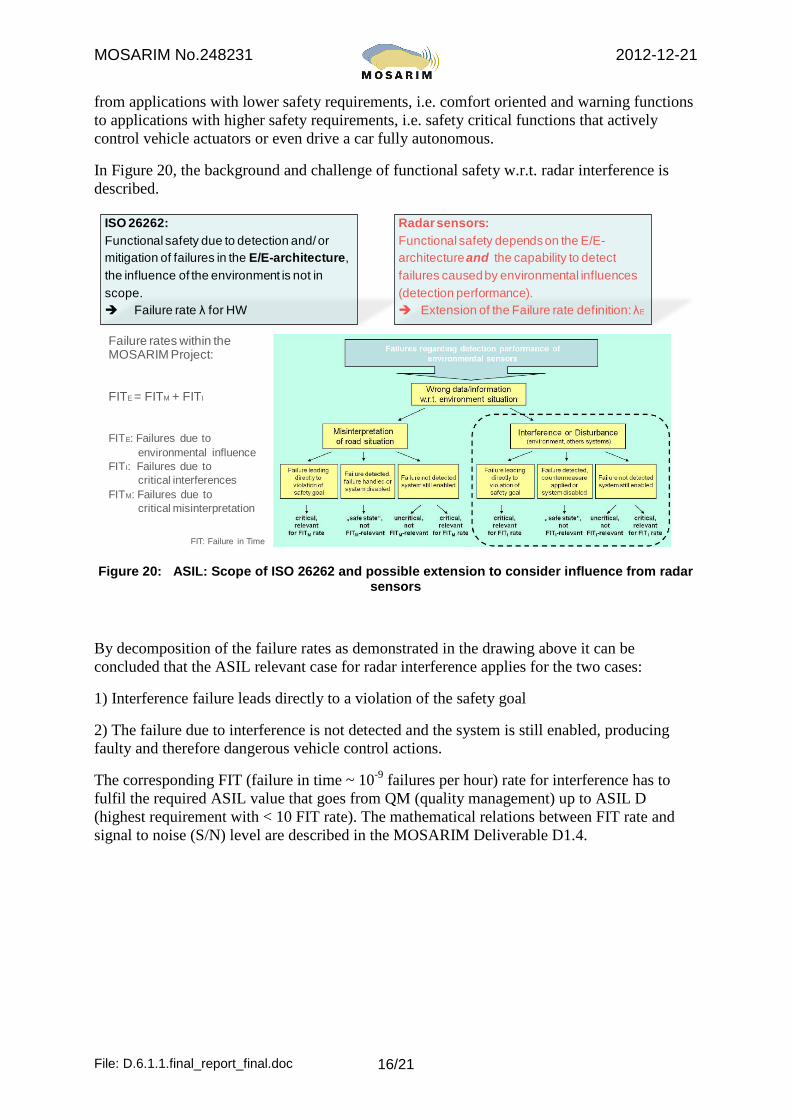
In Figure 20, the background and challenge of functional safety w.r.t. radar interference is described.
Failure rates within the MOSARIM Project:
FITE = FITM + FITI
FITE: Failures due to environmental influence
FITI: Failures due to critical interferences
FITM: Failures due to critical misinterpretation
ISO 26262:Functional safety due to detection and/ or mitigation of failures in the E/E-architecture, the influence of the environment is not in scope. Failure rate λ for HW
Radar sensors:Functional safety depends on the E/E-architecture and the capability to detect failures caused by environmental influences (detection performance). Extension of the Failure rate definition: λE
FIT: Failure in Time Figure 20: ASIL: Scope of ISO 26262 and possible extension to consider influence from radar
sensors
By decomposition of the failure rates as demonstrated in the drawing above it can be concluded that the ASIL relevant case for radar interference applies for the two cases:
1) Interference failure leads directly to a violation of the safety goal
2) The failure due to interference is not detected and the system is still enabled, producing faulty and therefore dangerous vehicle control actions.
The corresponding FIT (failure in time ~ 10-9 failures per hour) rate for interference has to fulfil the required ASIL value that goes from QM (quality management) up to ASIL D (highest requirement with < 10 FIT rate). The mathematical relations between FIT rate and signal to noise (S/N) level are described in the MOSARIM Deliverable D1.4.
MOSARIM No.248231 2012-12-21
File: D.6.1.1.final_report_final.doc 17/21
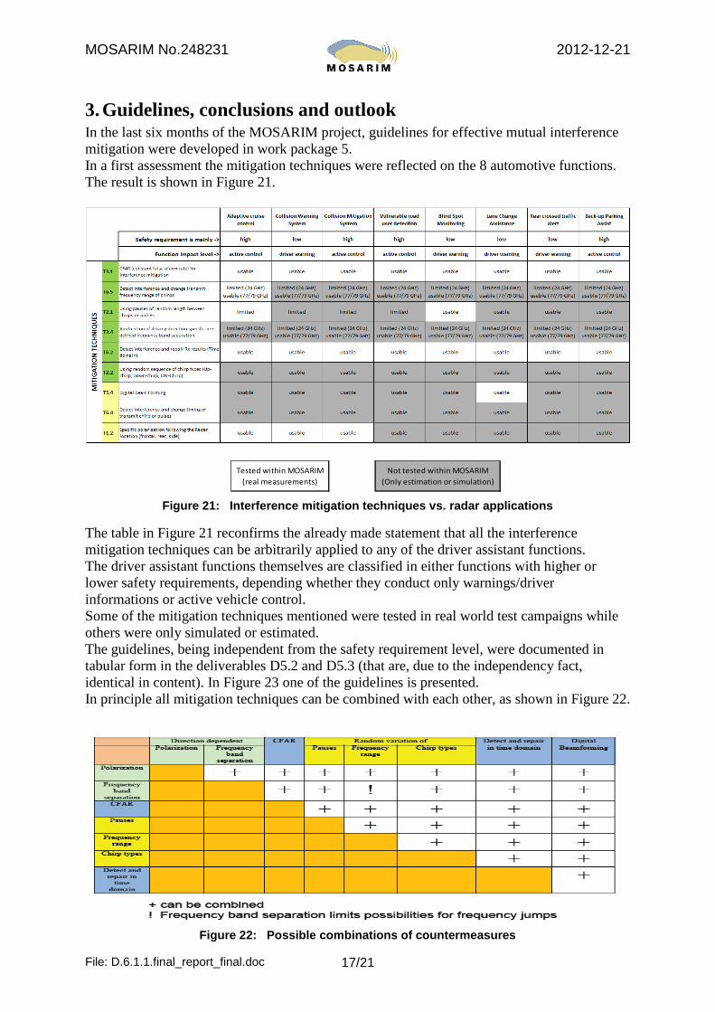
3. Guidelines, conclusions and outlook In the last six months of the MOSARIM project, guidelines for effective mutual interference mitigation were developed in work package 5. In a first assessment the mitigation techniques were reflected on the 8 automotive functions. The result is shown in Figure 21.
Tested within MOSARIM (real measurements)
Not tested within MOSARIM (Only estimation or simulation)
Figure 21: Interference mitigation techniques vs. radar applications
The table in Figure 21 reconfirms the already made statement that all the interference mitigation techniques can be arbitrarily applied to any of the driver assistant functions. The driver assistant functions themselves are classified in either functions with higher or lower safety requirements, depending whether they conduct only warnings/driver informations or active vehicle control. Some of the mitigation techniques mentioned were tested in real world test campaigns while others were only simulated or estimated. The guidelines, being independent from the safety requirement level, were documented in tabular form in the deliverables D5.2 and D5.3 (that are, due to the independency fact, identical in content). In Figure 23 one of the guidelines is presented. In principle all mitigation techniques can be combined with each other, as shown in Figure 22.
Figure 22: Possible combinations of countermeasures

MOSARIM No.248231 2012-12-21
File: D.6.1.1.final_report_final.doc 18/21
Figure 23: Guideline for mitigation technique “detect and change frequency”
An important topic and work, that was identified, but not solved within the timeline of the MOSARIM project, is the definition of the relation between needed interference to noise (I/N) ratio and needed mitigation margin for the driver assistant function portfolio. Figure 24 shows the expected relation among ASIL level, maximum allowed I/N and the function portfolio.
Max. allowed I/N
QM ASIL A ASIL B ASIL C ASIL D
Driver assistantfunction portfolio
Lower requirements(Collision warning,
Blind Spot Monitoring.Lane change assistance)
Higher requirements(Adaptive cruise control,
Collision mitigation,VRU protection)
exact relation still open
exact relation still open
mutual: xx dB mutual: yy dBincumbent: xx – zx dB incumbent: yy – zy dB
Figure 24: Relation between interference mitigation margin and I/N

MOSARIM No.248231 2012-12-21
File: D.6.1.1.final_report_final.doc 19/21
Not yet knowing the exact relationship between ASIL and max. allowed I/N, already at this stage an apportionment of interference contribution between mutual (i.e. the automotive radars) and incumbent (i.e. all other radio devices in the same frequency band) can be made. This is commonly done at ITU-R level where different radio service levels (primary, co-primary and secondary/all others) are defined and apportionment is typically done by 89%(primary) to 10%(co-primary) to 1%(secondary). This results in I/N level that differ by 20 dB from primary to secondary services, i.e. a so-called additional “safeguard-margin” to keep interference influence by secondary services rather low.
To come-up with first indicative I/N values as a preliminary conclusion and outlook, the following scenario, as drawn in Figure 25, can be used as a starting point for possible drafting automotive interference mitigation standards.
Figure 25: Dependency of I/N limit, mitigation margin and highest possible I/N
(with mitigation techniques applied)
For automotive radars, without any mitigation technique applied, the interference power can exceed the noise level by 20 to 50 dB. For incumbent users with higher EIRP emissions this value can even reach 70 dB or more.
To assure an I/N level of 0 or – 10 dB, reliable mitigation techniques in the order of min. 50 dB mitigation margin are needed. For ASIL D applications the mitigation margin for incumbent frequency users is set to zero because no controllability and guarantee for always proper and full working mitigation technique can be made.
Recent discussions with administrative bodies provided a first hint to place radar interference mitigation standardization work within ETSI. This leaves full control to the automotive car manufacturers and radar suppliers when agreeing upon and drafting the relevant testing procedures for a robust, and interference-free or interference-minimized radar operation.

MOSARIM No.248231 2012-12-21
File: D.6.1.1.final_report_final.doc 20/21
4. Acknowledgement All MOSARIM project partners thank the European Commission for supporting the described work within the 7th framework programme.
Dr.-Ing. Martin Kunert
Coordinator of the MOSARIM project

MOSARIM No.248231 2012-12-21
File: D.6.1.1.final_report_final.doc 21/21
List of all beneficiaries with the corresponding contact name:
MOSARIM Logo:
MOSARIM Website: www.mosarim.eu