project final report - european...
TRANSCRIPT

Grant agreement no: 605410
Public | Restricted Confidential
LOWFLIP_Final report Page 3 of 53
PROJECT FINAL REPORT
Final publishable summary report
Grant Agreement number 605410
Project Acronym LOWFLIP
Project title Low cost flexible integrated composite process
Funding Scheme THEME [TPT.2013-1TPT.2013-1.] [Technology transfer in the area of Transport]
Period covered From 01-10-2013 to 30-09-2016
Name of the scientific
representative of the project’s
coordinator, Title and organisation
Herr Dr.-Ing. Stefan Carosella, head of Composites Research Group, Institut für Flugzeugbau, Universität Stuttgart (USTUTT)
Tel +49 711 685-60245
E-mail [email protected]
Project website address http://www.lowflip.eu/

Grant agreement no: 605410
Public | Restricted Confidential
LOWFLIP_Final report Page 4 of 53
1. Executive summary
The goal of project LOWFLIP was the development of low-cost and automated production
processes for CFRP parts, which can be used for different industrial sectors. 10 partners
from 5 European countries worked together from October 2013 until October 2016 to
realize technologies, which are capable of being introduced in an industrial environment
at the end of the project.
3 representative demonstrator parts were identified from the end users in the project: An
aeronautical tail cone section by AERNNOVA, an automotive sandwich panel by
CARBURES and a truck front wall by KÖGEL. Despite the different requirements from
each industrial sector, a compromise solution for a newly developed material system by
SGL could be found. The material offers a unique combination of out-of-autoclave
processing at moderate temperatures, a high glass transition temperature, excellent
mechanical properties and fast curing capabilities.
Innovative tooling concepts to achieve a fast curing cycle were developed and produced,
such as 3D-membranes with integrated resistive heating, a composite tooling with an
embedded heating circuit and a fluid-heated metallic mould with low thermal mass.
Two different processes were realized to be able to produce both small & complex parts
as well as large components. For small parts, a robot-mounted pick & place unit has been
developed within the project, which is able to transfer different types of materials
accurately onto a mould. A combination of an elastic membrane and a 3D-membrane
then drape the material into the final shape and perform the final curing, without needing
additional machinery such as autoclaves or presses. In this way, a highly flexible process
is given which can be easily adapted to different part geometries.
A novel ply placement approach has been developed by the consortium from scratch to
realize large parts with a size of more than 1x1 m. By transferring the know-how from
hand layup to an automated, industrial solution, a highly productive process could be
realized, which can compete with existing industrial solutions regarding layup rate – at
significantly lower investment costs.
In both cases, the project objectives could be achieved and industrial solutions were
developed, which are now ready to be transferred into the industry.

Grant agreement no: 605410
Public | Restricted Confidential
LOWFLIP_Final report Page 5 of 53
2. Summary description of the project context and objectives
TODAY’S CHALLENGES
Fibre-reinforced polymer composite materials are leading candidates as
component materials to improve the efficiency and sustainability of many transport
modes. The advantages of high performance composites are numerous: lighter
weight, optimum strength and stiffness, improved fatigue life, and corrosion
resistance. These benefits translate into greater weight savings resulting in
improved performance, greater payloads, fuel savings and emissions
reductions.
The current manufacturing processes still represent high capital investments for SMEs
which are a major barrier for their deployment in sectors like the automotive, transport and aircraft industries.
There are a number of technical issues that still need to be
resolved before any significantly increased uptake of composites
by the automotive sector can be expected.
OBJECTIVES
The specific scientific and technical objectives are the following: - To develop, assess and analyse new out-of-autoclave snap-cure prepreg
materials for fast curing and easy and low cost automated manipulation
- To develop low cost and flexible multifunctional handling, placement and
draping solutions for both small complex parts and big structures
- To reduce composite manufacturing process steps by selective, fast and
energy efficient tooling technologies
- To develop simulation tools to support the automation of the process with
regards to material drapability, curing optimization and crash behaviour
- To design and produce prototype manufacturing cells that integrate the
technologies validated at laboratory scale
LOWFLIP objective was to develop a low cost flexible and integrated composite
parts manufacturing process for the needs of different transport sectors, which
will require minimum investments
The quantified targets of the project are:
- A reduction of the investment costs compared to SoA processes of 50%
- A reduction of the energy consumption compared to SoA processes of 50%
- Equal productivity compared to SoA
- Equal technical performance compared to SoA

Grant agreement no: 605410
Public | Restricted Confidential
LOWFLIP_Final report Page 6 of 53
CONSORTIUM
In order to reach the targeted objectives, a strong consortiums has been set up, which
consists of 2 research institutes, 3 end users, tooling and material experts, as well as
partner for simulation software and an automation company, these are:
University of Stuttgart, Institute of Aircraft Design
http://www.ifb.uni-stuttgart.de
Fundacion Tecnalia Research and Innovation
http://www.tecnalia.com/en/
AERNNOVA ENGINEERING SOLUTIONS IBERICA SA
http://www.aernnova.com/en/
CARBURES EUROPE SA
http://carbures.com/
KÖGEL TRAILER GMBH & CO KG
http://www.koegel.com/de/
ALPEX TECHNOLOGIES GMBH
http://www.alpex-tec.com/de/
SGL CARBON GMBH
http://www.sglgroup.de
MECAS ESI SRO
https://www.esi-group.com/cz
FILL GESELLSCHAFT MBH
http://www.fill.co.at/
AYMING
http://www.ayming.com/

Grant agreement no: 605410
Public | Restricted Confidential
LOWFLIP_Final report Page 7 of 53
3. Description of the main S&T results/foregrounds
LOWFLIP aimed at developing new technologies in many different areas along the
process chain of fiber reinforced polymers with the goal to set up automated production
processes which require significantly lower invest than comparable state-of-the-art
technologies. Starting with a new resin system featuring out-of-autoclave snap-cure
properties with heavy-tow carbon fibers, innovative tooling concepts with fast heating
and low energy-consumption were developed together with new process approaches for
the automated production of cfrp parts. All developments have been accompanied by
simulation methods, which served as “virtual support” during the development and
application of the technologies. The developments were finally integrated into full-scale
production cells, which demonstrated their capability on the example of 3 demonstrator
parts from the automotive, truck and aeronautic sector.
The following chapter describes the main results of the different technological
developments of LOWFLIP.
3.1. Demonstrator parts
The first task was the selection of representative demonstrator parts of the different
transport sectors. In case of the automotive branch, a cross-beam structure has been
identified by the partner Carbures, which has to withstand bending and torsion loads. It
has a length of about 1.2m and consists of a sandwich structure with cfrp skins and a
milled foam core. The parts complex shape in combination with its sandwich layup
requires a highly flexible production process. The targeted volume of production has been
defined as 10,000 parts per year, which results in a required curing cycle of about 30
mins.

Grant agreement no: 605410
Public | Restricted Confidential
LOWFLIP_Final report Page 8 of 53
The truck demonstrator is the largest of all three demonstrators. With a size of
2.5x2.9m, it required a novel automated production process with large tapes to meet the
requirements of the project. The selected front wall shields the driver’s cabin from the
trailer and has to prevent the carried load from penetrating through. Thus it is a safety
related part and has to fulfil the DIN standard EN 12642-XL, which requires a maximum
load of 13.500 kN on the front wall. Geometrically, it features strongly double-curved
areas, which were slightly changed from the original part to obtain a suitable design for
cfrp materials. Moreover, the design flexibility arousing from the use of textile materials
allowed for an aerodynamic design, which can potentially reduce the drag and thus CO2
emission during the life cycle of a truck.
Figure 2. Truck demonstrator by Kögel – front wall
The third demonstrator from the aeronautic sector is a typical stiffened skin panel from a
tail cone section. The double-curved skin is stiffened with T-stringers, which have to be
preshaped in a separate forming step and joined with the skin by co-curing both
elements.
Here, the research activites not only focused on the production process, but also on the
material quality and its damage tolerance, requiring additional ice-shedding impact tests
on a comparable structure.
Figure 1. Automotive demonstrator by Carbures – cross-beam

Grant agreement no: 605410
Public | Restricted Confidential
LOWFLIP_Final report Page 9 of 53
Figure 3. Aeronautical demonstrator by Aernnova – tail cone section
During the first stage of the project, the requirements on both the material and the
processes to be developed were defined on the basis of these three demonstrator parts.
It is obvious, that each industrial sector has different needs, which are difficult to meet in
just one material or one process. Therefore, it has been tried to find common ground and
to define the requirements as a compromise between different applications, which can be
seen in Table 1.
3.2. New prepreg materials
The highly efficient processes and demanding applications planned in the LOWFLIP
project required the development of novel prepreg materials featuring a unique
combination of properties, such as:
- “Snap-cure” type curing behaviour: fast curing at elevated temperatures in
combination with a high thermolatency
- Tailored tack and viscosity profile of the resin to enable the application of
automated handling and out-of-autoclave curing processes
- Long shelf-life and reliable processing at room temperature
- High glass transition temperature (in the range of the curing temperature) and
mechanical performance
A selection of the specific development goals that were derived from these general
demands and the input collected from the project partners at the beginning of LOWFLIP
is listed in Table 1.
Table 1. Goals for the development of the novel prepreg materials
Property Value
Cure time ≤ 15 min
Cure temperature 120 °C
Applicable heating rate ≥ 10 °C/min
Curing process Out-of-autoclave
Post-cure No
Glass transition temperature ≥ 120 °C
Shelf-life at room temperature ≥ 21 d
Shelf-life at -18 °C ≥ 6 months
Tack at room temperature Low

Grant agreement no: 605410
Public | Restricted Confidential
LOWFLIP_Final report Page 10 of 53
Resin type Epoxy
Fiber type Heavy tow industrial carbon
fiber (50k)
Textile Unidirectional and biaxial
(±45°) non-crimp fabric
Fiber areal weight ≥ 300 g/m²
Impregnation level Full / semi
Curing behaviour, storage stability, glass transition temperature and other important
properties of prepreg materials are determined by the employed matrix system. For this
reason, the development of a tailored resin formulation for the novel prepreg materials
was a crucial point. As a first step, a suitable combination of curing agent and accelerator
showing the desired snap-cure type curing behavior was identified in an extensive
screening study. In a second step of the development, the base resin mixture of the
formulation was optimized with regard to viscosity profile, tack properties and glass
transition temperature.
An impregnation process adapted to the properties of the resin system was evaluated
and optimized on a prepreg pilot line. After several iteration loops, which considered
feedback from the project partners, a snap-cure epoxy resin system (“SCE79”) was
finalized that is able to fulfil all targets of the LOWFLIP project.
The viscosity profiles determined by rheological measurements of resin system SCE79
are shown in Figure 4.
Figure 4. Dynamic (left) and isothermal (right) viscosity profiles of the
developed snap-cure resin system SCE79
The dynamic profiles show a very high viscosity at room temperature indicating a solid-
like behavior of the resin which results in the desired low tack of prepregs based on this
resin system. The viscosity decreases rapidly with increasing temperature and low
minimum viscosity values are observed which allow for a high resin flow in out-of-
autoclave curing processes without the need to apply high pressure.
The isothermal viscosity profiles demonstrate the high curing performance at elevated
temperatures and the excellent thermolatency of the developed resin system. While
there is only a slight increase of viscosity measured at 80 °C within 45 min, rapid
viscosity increases are observed at temperatures of 100 °C and higher. A stable viscosity
niveau, indicating a largely completed curing reaction, is for example reached in less than
Grant agreement no: 605410
Public | Restricted Confidential
LOWFLIP_Final report Page 11 of 53
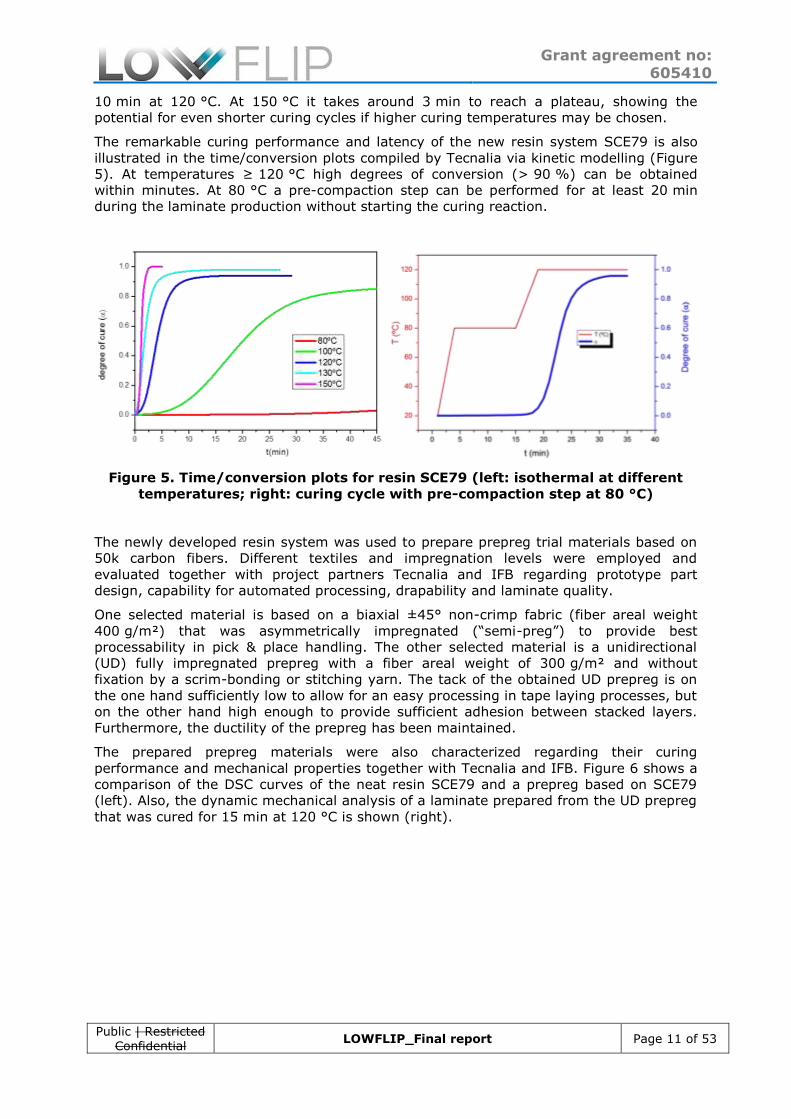
10 min at 120 °C. At 150 °C it takes around 3 min to reach a plateau, showing the
potential for even shorter curing cycles if higher curing temperatures may be chosen.
The remarkable curing performance and latency of the new resin system SCE79 is also
illustrated in the time/conversion plots compiled by Tecnalia via kinetic modelling (Figure
5). At temperatures ≥ 120 °C high degrees of conversion (> 90 %) can be obtained
within minutes. At 80 °C a pre-compaction step can be performed for at least 20 min
during the laminate production without starting the curing reaction.
Figure 5. Time/conversion plots for resin SCE79 (left: isothermal at different
temperatures; right: curing cycle with pre-compaction step at 80 °C)
The newly developed resin system was used to prepare prepreg trial materials based on
50k carbon fibers. Different textiles and impregnation levels were employed and
evaluated together with project partners Tecnalia and IFB regarding prototype part
design, capability for automated processing, drapability and laminate quality.
One selected material is based on a biaxial ±45° non-crimp fabric (fiber areal weight
400 g/m²) that was asymmetrically impregnated (“semi-preg”) to provide best
processability in pick & place handling. The other selected material is a unidirectional
(UD) fully impregnated prepreg with a fiber areal weight of 300 g/m² and without
fixation by a scrim-bonding or stitching yarn. The tack of the obtained UD prepreg is on
the one hand sufficiently low to allow for an easy processing in tape laying processes, but
on the other hand high enough to provide sufficient adhesion between stacked layers.
Furthermore, the ductility of the prepreg has been maintained.
The prepared prepreg materials were also characterized regarding their curing
performance and mechanical properties together with Tecnalia and IFB. Figure 6 shows a
comparison of the DSC curves of the neat resin SCE79 and a prepreg based on SCE79
(left). Also, the dynamic mechanical analysis of a laminate prepared from the UD prepreg
that was cured for 15 min at 120 °C is shown (right).

Grant agreement no: 605410
Public | Restricted Confidential
LOWFLIP_Final report Page 12 of 53
Figure 6. DSC of a prepreg compared to the neat resin SCE79 (left) and DMA of a
unidirectional laminate of the prepreg (right) (curing cycle: 15 min at 120 °C)
The reaction peak observed in the DSC exhibits the same characteristics (e.g. onset and
peak temperature) for the neat resin and the corresponding prepreg which indicates that
the excellent curing behaviour of the resin is retained also in combination with the carbon
fibers. The DMA shows a well-defined glass transition at a temperature between 120 -
130 °C (E’-onset) which is above curing temperature. This allows for a hot demoulding of
cured composite parts.
Despite the high curing performance at elevated temperatures a long shelf-life of at least
4 weeks at room temperature was obtained for the resin and prepregs based on it
(determined by viscosity and DSC measurements).
The results of mechanical testing of the UD prepreg are shown in Table 2. Two different
curing methods were used in order to investigate their influence on the mechanical
properties and to assess the mechanical potential of the developed material system. The
first method was a vacuum-assisted process (vacuum bag curing in an oven) and the
second one was a standard hot press process applying a pressure of 5 bar. A pre-
compaction step at 80 °C prior to curing at 120 °C was conducted in both methods.
Table 2. Mechanical properties of unidirectional laminates prepared under
different conditions (curing cycle in both cases: 10 min at 80 °C + 15 min at 120 °C)
Property Standard Values obtained with UD prepreg
(SCE79, 50k CF, FAW 300 g/m²)
Vacuum bag
(30 mbar vac.)
Compression
molding (5 bar)
Fiber volume content [%] EN 2564 56.7 (± 0.9) 62.4 (± 2.3)
0° Tensile strength [MPa] EN 2561 1737 (± 54) 1872 (± 43)
0° Tensile modulus [GPa] EN 2561 129.8 (± 8.5) 133.1 (± 2.0)
90° Tensile strength [MPa] ISO 527-5 36.9 (± 7.8) 56.2 (± 5.7)
90° Tensile modulus [GPa] ISO 527-5 7.9 (± 0.3) 8.8 (± 0.2)
0° Compressive strength [MPa] ISO 14126 1133 (± 117) 1282 (± 80)
0° Compressive modulus [GPa] ISO 14126 118.2 (± 3.8) 123.0 (± 3.0)
Interlaminar shear strength [MPa] EN 2563 70.1 (± 1.6) 83.2 (± 3.2)
0° Flexural strength [MPa] ISO 14125B 1300 (± 34) 1388 (± 13)

Grant agreement no: 605410
Public | Restricted Confidential
LOWFLIP_Final report Page 13 of 53
0° Flexural modulus [GPa] ISO 14125B 108.0 (± 4.8) 105.5 (± 2.5)
90° Flexural strength [MPa] ISO 14125B 60.5 (± 4.8) 74.9 (± 2.9)
90° Flexural modulus [GPa] ISO 14125B 6.9 (± 0.3) 8.5 (± 0.2)
In-plane shear strength [MPa] ISO 14129 56.6 (± 0.6) not tested
In-plane shear modulus [GPa] ISO 14129 3.9 (± 0.1) not tested
It can be seen that the press process at 5 bar generally leads to higher mechanical
properties which can be explained by a higher fiber volume content and higher laminate
quality, both resulting from the increased pressure level compared with the vacuum-
assisted curing process. The values obtained with the vacuum bag setup are nevertheless
on a satisfactory level, especially if considering the short curing cycle and rather simple
process.
In conclusion, prepreg materials based on 50k carbon fibers and a novel snap-cure epoxy
resin system (“SCE79”) were developed by SGL according to the demands of the
LOWFLIP project. These materials feature a fast cure at elevated temperatures (e.g.
15 min at 120 °C), a high glass transition temperature of 125 °C, long shelf-life at room
temperature (≥ 4 weeks) and competitive mechanical properties. The new prepregs were
further adjusted to automated handling processes and out-of-autoclave curing of large
composite parts. Compared to standard prepreg materials cured in traditional autoclave
processes, significant reductions of cycle times, energy consumption and investment
costs can be achieved.
3.3. Tools for fast & energy-efficient heating
In order to meet the demands of an energy-efficient process, new innovative tooling
concepts were investigated within LOWFLIP which should provide mainly two features:
Low energy-consumption and fast heating capabilities. State-of-the-art tooling are
typically a metallic solution milled out of block materials such as aluminium or invar steel
with high thermal masses. Therefore, different concepts were investigated by the
partners.
Automotive
The design of the automotive tooling aims to manufacture 10000 + pieces per year. To
do so the developed process aims to use two tools, which rotate between a preparation
and a curing phase.
1. Draping of the bottom skin onto the tool
2. Forming of the bottom sin with a heated membrane
3. Positioning of the core 4. Draping the top skin 5. Finalizing the form and the curing 6. Cooling and demolding
The tool has to provide fast heating and cooling ramps as they are key issues for the
process. To ensure fast heating and cooling the tool has to be a low mass solution, which
is still capable of withstanding of the occurring forces.

Grant agreement no: 605410
Public | Restricted Confidential
LOWFLIP_Final report Page 14 of 53
The solution is an aluminum tool with a sophisticated design for the heating circuit. The
rips inside the tool provide a larger surface to increase energy exchange between the tool
and the medium. They also cause a turbulent flow, which increases the energy exchange
as well. A suitable heating/cooling device is very important to use the tools benefits.
Figure 7. Automotive tool design
Figure 8. Final tool (heating test and with part) and heating ramp
The tool was manufactured and the heating ramp was tested. The results were very
promising and showed the property to heat up very fast. The drop down in the graph
derives from the refilling of the heating device with cold water to compensate the volume
of the tool. For the production process the heat transfer between the two tools will be
optimized and the drop down is not relevant any more.
The final process was changed and the forming of the bottom skin is not performed any
more, which saves time and allows an even faster production cycle.
Transportation
The transportation industries need fewer parts than the automotive sector, but the parts
are much larger. The demonstrator for transportation is very large with a size of about
3 m x 2,5 m and has a 3-D shaped structure. The issues hereby are the tape-laying and
the energy consumption for the curing.
The energy consumption of a steel tool to heat such a tool would be 179 kWh. An
optimized version with 30 mm steel mould and a substructure made of steel still would
require about 45 kWh; the convection of the larger surface is not included. To reduce the
mass significantly the use of CFRP with embedded heating wires was focused. The
designed CFRP tool needs about 4 kWh. Furthermore the heating ramp of the CFRP tool
is much faster than the heating appears close to the surface. The values of the energy
consumption will be higher as the calculations did not include the convection, the parts
and thermal insulation.
To manufacture a CFRP tool a master tool is needed, which is made of plastics or
sometimes timber. The GFRP is laminated on the master tool, which means all properties
of the GFRP tool have to be part of the master tool.

Grant agreement no: 605410
Public | Restricted Confidential
LOWFLIP_Final report Page 15 of 53
Figure 9: Master tool and CFRP tool
Figure 10. Manufactured master tool and final CFRP tool
The master tool was made of medium density fiber board and varnished to provide a
vacuum tight surface for manufacturing the CRFP tool. The CRFP tool has embedded
heating wires and a honeycomb structure underneath to ensure a high stability for the
tape laying process.
Aeronautics
The aviation industry has very complex shaped parts that often have integrated parts,
like stringers. Therefore the production is based on manual work and only can provide
expensive parts at small quantities. The performing is usually made inside the metal
curing tools, which takes them out of the production process whilst curing. The
production uses autoclaves to cure the parts, which are run with variotherm heating
ramps. The energy consumption is enormous.
The idea to improve the manufacturing for the aviation industry is to separate the
preforming and the curing. The preform tool is made of an economic material and
available in large quantities. A membrane is added to the preform tool to manufacture
the preform. To cure the part a heatable metal tool is used, which remains at the curing
temperature. As the preforms are quite soft and easy to damage the transfer of the
preform will be done with the membrane. The curing tools are attached to preform tool
and the membrane is evacuated to the metal tool. As the tools fits perfectly with each
other the fibers aren’t moved.
Figure 11. Preform tool, with membrane and inserts and the transferred
membrane at the curing tool

Grant agreement no: 605410
Public | Restricted Confidential
LOWFLIP_Final report Page 16 of 53
Figure 12. Preform tool and curing tool
Figure 13. Silicone membrane
The membrane was partly thicker than expected, which led to wrinkles. With some
adjustments to the tool the process is still usable.
3.4. Development of innovative, low-cost and automated
manufacturing technologies
Due to the different requirements on part geometry between the automotive and
truck/aeronautic sector, two different manufacturing approaches had to be defined to be
able to realize the demonstrator parts with an automated process.
In case of the small and complex geometries addressed by the automotive demonstrator,
a pick & place approach combined with an elastic membrane was developed.
For large parts with lower curvature such as the truck front wall and the tail cone section,
a novel tapelaying process has been designed from scratch.
Figure 14. Tecnacomp baseline process (left) and LOWFLIP concept for small &
complex parts
As it is shown in Figure 14, the approach for small & complex parts consists of a pick &
place unit mounted on a robot, which has originally been developed by Tecnalia. The pick
& place device should then be combined with a newly developed membrane draping
approach, which consists of two different types of membrane material: A highly elastic
membrane in order to drape the material on the complex mould and a 3D-membrane

Grant agreement no: 605410
Public | Restricted Confidential
LOWFLIP_Final report Page 17 of 53
with integrated resistive heating circuits that is later heated up to cure the part. In this
way, an automated process chain is given that can be applied to varying geometries and
materials.
In order to find suitable solutions for the membranes, durability tests were performed.
The results showed that the right membrane material is crucial to obtain a robust
process, especially as epoxy based resin systems can significantly reduce the membrane
properties after several curing cycles. By analysing membranes mechanically, a material
with a good combination of flexibility and robustness was found.
Moreover, pick & place tests were performed on a lab-scale to test different grippers
which are capable of transferring a stack of prepreg material from a feeding table to the
mould. The lab-scale trials were validated on the automotive tool provided by the partner
ALPEX and led to the design of the full-scale cell by FILL. It features a pneumatic gripper
system that is mounted on a robot, which can pick up single plies or stacks from a
feeding table and place them on the mould. In order to be able to deal with different
types of material, different pneumatic gripper solutions are combined within one device.
Moreover, the grippers are mounted on several axes, so that their position can be
adjusted in order to deal with different cut geometries. It is also possible to pre-shape
the stack before placing it onto the mould, so that a reproducible positioning can be
achieved.
Figure 15. Full-scale production cell for small & complex parts
The full-scale cell has been evaluated on the basis of the production of several
automotive demonstrator parts. A cycle time of around 20 mins can be achieved with the
system if one mould is used. By using two moulds which are processed in parallel, an
optimised cycle time of 10 mins is realistic. Since an overall production cycle of 30 mins
has been targeted, it was shown that the combination of a fast-curing material and high
productivity was successful.
For large component, a novel tapelaying approach has been developed from scratch. The
basic idea is to separate the material feeding from the compaction system by designing
two gripper units, which position a tape of unidirectional material over a mould and a
compaction unit which then forms and consolidates the tape on the mould. Available
market solutions (Automated Fibre Placement, Automated Tapelaying) typically consist of
highly complex, integrated devices which are mounted on a gantry or an industrial robot.
Moreover, they are mainly designed for the use with one single type of material. The
Grant agreement no: 605410
Public | Restricted Confidential
LOWFLIP_Final report Page 18 of 53
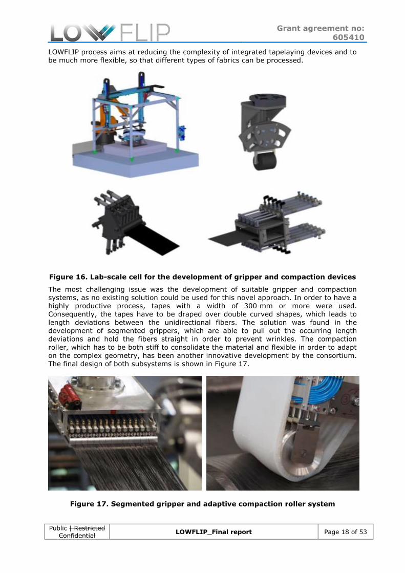
LOWFLIP process aims at reducing the complexity of integrated tapelaying devices and to
be much more flexible, so that different types of fabrics can be processed.
Figure 16. Lab-scale cell for the development of gripper and compaction devices
The most challenging issue was the development of suitable gripper and compaction
systems, as no existing solution could be used for this novel approach. In order to have a
highly productive process, tapes with a width of 300 mm or more were used.
Consequently, the tapes have to be draped over double curved shapes, which leads to
length deviations between the unidirectional fibers. The solution was found in the
development of segmented grippers, which are able to pull out the occurring length
deviations and hold the fibers straight in order to prevent wrinkles. The compaction
roller, which has to be both stiff to consolidate the material and flexible in order to adapt
on the complex geometry, has been another innovative development by the consortium.
The final design of both subsystems is shown in Figure 17.
Figure 17. Segmented gripper and adaptive compaction roller system

Grant agreement no: 605410
Public | Restricted Confidential
LOWFLIP_Final report Page 19 of 53
After several iterations, the design of the final full-scale production cell for large parts
was found. It consists of three industrial robots mounted on a linear axis, which are used
for taking up the material from a ply cutter and then position the tape over the mould.
Depending on the required fiber orientation, the tool can be rotated, so that any
demanded angle can be realized. The compaction roller is mounted on the third robot,
which then presses the tape on the mould. A smart off-line programming software has
been a key to finally realize the demonstrator parts in this automated process.
Figure 18. Full-scape production cell for large parts
The process is competitive with regards to its productivity with current AFP processes.
During the production of the truck front wall, a layup rate of around 10-19 kg/hour could
be achieved, depending on the complexity of the geometry. Here, a tape with 300 mm
width and a fiber areal weight of 300 g/m² has been used. During the process, the mould
is slightly heated up to increase the tack of the prepreg material. A curing cycle of 40
mins could be achieved with the available mould, which could further be decreased by
increasing the heat-up rate of the mould. The material scrap rate was in the range of less
than 10% and could be reduced to less than 5% by optimizing the robot programming
and thus the tape lengths.
In summary, two innovative automated production processes have been developed by
the LOWFLIP consortium, which allow for the production of complex CFRP components
with high volume. Due the combination of fast out-of-autoclave curing, high flexibility
with regards to part geometries and materials, as well as low investment costs, they
provide a unique solution on the market for part suppliers.
3.5. Simulation tools for composite manufacturing and part
design
In order to have a low cost part from composite material, apart of the direct costs of
material and energy consumed during its manufacturing, it is necessary to be able to
define part’s design and the way how to produce it in a reasonable timeframe with as
little costs as possible. It will be only possible if engineers can avoid experiments with
real prototypes and determine part characteristics, manufacturability and repeatability
before it comes to the production. This can be enabled by introducing virtual tools for
assessment of component properties and manufacturing process feasibility.

Grant agreement no: 605410
Public | Restricted Confidential
LOWFLIP_Final report Page 20 of 53
Within the project there have been tested and also validated several simulation tools and
possibilities for various aspects of manufacturing process and both static and dynamic
responses of components produced from the new material with a given forming and
curing cycles.
Forming behaviour of the new material has been tested on an identified simple tool, so
called double dome, which is small enough for basic experiments but at the same time
enables to investigate and validate several forming phenomena occurring during
composite forming process due to the availability of flat areas, single curvature and
double curvature areas.
Figure 19. Mesoscopic simulation model of the draping process (top) and
experimental draping test rig
With a basic characterization tests such as cantilever test, bending test and bias
extension test, a material behaviour under forming conditions such as prepreg/semipreg
stiffness, bending stiffness, shear modulus, has been identified and obtained material
properties were used for virtual forming simulations. Two approaches have been
investigated, microscopic and macroscopic, each for different type of reinforcement used.
Results of macroscopic forming simulation is compared with experimental forming. Part
outlines are well corresponding as well as defects in the part, see Figure X-Y2 and Figure
X-Y3

Grant agreement no: 605410
Public | Restricted Confidential
LOWFLIP_Final report Page 21 of 53
Figure 20. Macroscopic model – simulation result
Figure 21. Macroscopic model – detail side
In order to precisely predict fiber architecture parameters, the use of mesoscopic
material models has been investigated within WP5. Here, the yarns and matrix are
represented as separate materials in the simulation model with different properties.
These properties were measured experimentally with bias extension and cantilever tests
at different temperatures, since the properties of the matrix material are highly
temperature dependent. It could be shown that deviations from the ideal fiber
architecture occur in the simulation model to the same degree as in reality, if all
parameters are implemented correctly. These deviations are for example gaps or
undulations, which can be seen in Figure 22.

Grant agreement no: 605410
Public | Restricted Confidential
LOWFLIP_Final report Page 22 of 53
Figure 22. Mesoscopic material model and draping simulation results with
occurring defects
One of the manufacturing processes within this project was an automatic tape-laying
process, for which there has been build a new tool for analysing mold/part surface
complexity with respect to laying procedure, such as starting point for laying, direction of
laying, tape width. This tool enables the user to analyse a curvature of part or mold
surface in the tape direction and orthogonal direction, Figure X-Y4, and tapes distribution
on the part with differences of lengths of edges of a single tape laid on the tool, Figure X-
Y5 and of course tapes themselves on the surface, Figure X-Y6.
Figure X-Y4 Surface curvature in tape direction and layup direction
Figure X-Y5 Tapes on the part and edge lengths’ differences
Virtual modeling has a significant role in components’ design. There have been built
several numerical models to iterate on final dimensioning of a demonstrator part – trailer
front wall structure, and an optimal one found for prescribed loading states with

Grant agreement no: 605410
Public | Restricted Confidential
LOWFLIP_Final report Page 23 of 53
identified material parameters. Final shape to be seen at Figure X-Y6 and thicknesses
with corresponding results showing the part is within the Tsai Wu criteria and also below
maximum allowed deformation Figure X-Y7.
Figure X-Y6 Final design - Thickness and mass of parts
Part Inner
wall
Outer wall
L1 L2
Side beam
t1 t2
Inner
beam
Bottom
part
Front wall
substructure
Thickness
[mm]
1.5 2.4 3.6 3 5 3 4
Mass [kg] 26.8 19.7 13.3 4.6 0.9 9.8 2 92.4
Table Z Final design - Thickness and mass of parts
Figure X-Y7 Final design - Tsai Wu failure creterion and displacements
Another manufacturing process within the project was the CARBURES automotive
demonstrator production. A prediction of the displacements with PAM-DISTORTION was
performed, and correlated quite well with reality. The part had slight shrinkage during

Grant agreement no: 605410
Public | Restricted Confidential
LOWFLIP_Final report Page 24 of 53
the curing and coooling. Neither internal stresses nor displacements after the curing and
cooling phase and before demoulding were also very big.
Figure 23: Stresses and displacements of automotive demonstrator after curing
and before demoulding. Units in Pascals (pa) and meters (m)
Figure 24: Distortions obtained after demoulding. Units in meters (m)
Figure 25: Distortions obtained after demoulding. Units in meters (m)
Therefore, an accurate correlation between simulation and experimental trials was
carried out. Slight angular deformations and part shape displacements were measured as
predicted with the model. The methodology and the software used it is therefore
validated with the manufacturing trial.
Damage Tolerance behavior of the composite materials at low energy impacts is crutial to
be known, due to has a great importance in sizing allowables of aeronautical structures.
This material knowledge can be done by means of big test campaigns spending a lot of
time in manufacturing, inspecting, cutting, testing and evaluating test results, or can be
done by means of virtual testing by simulation.
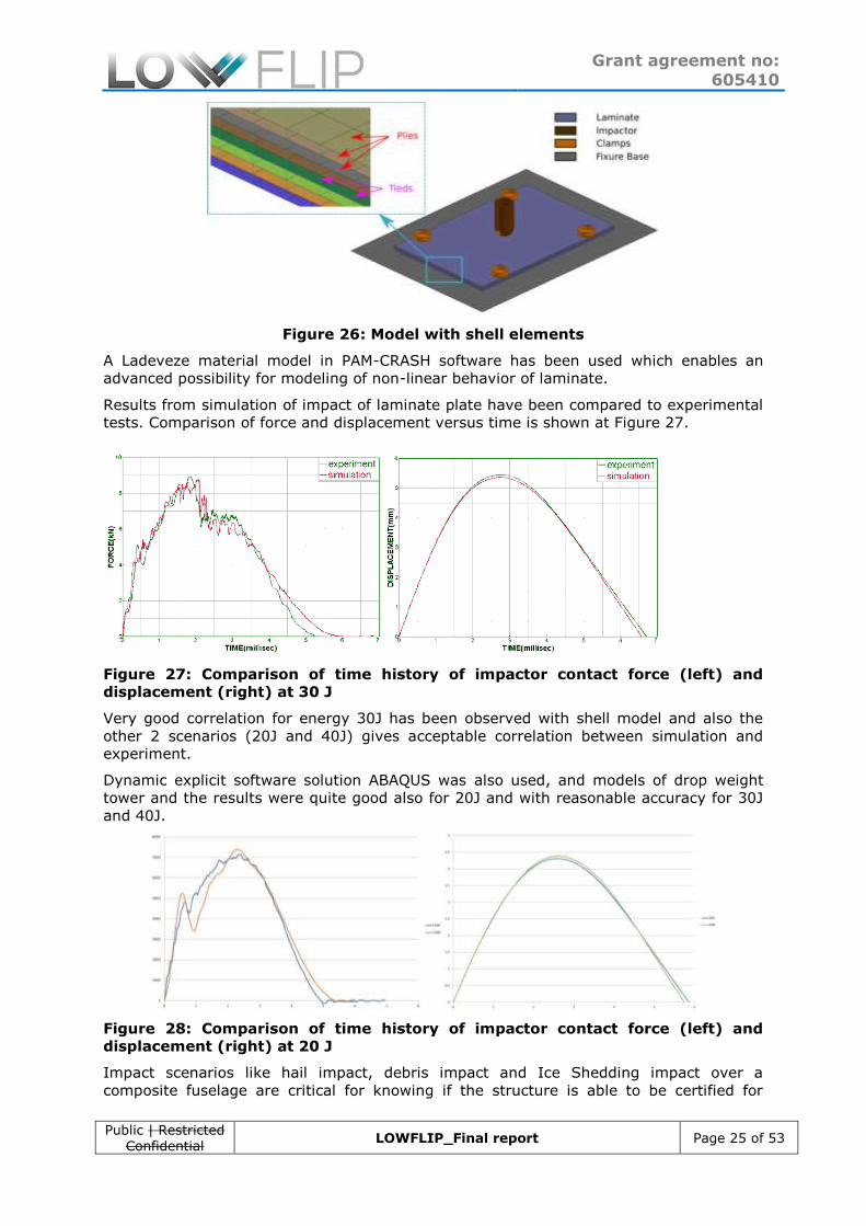
There has been performed a simulation of dynamic material response on impact at
different energies with a shell model, which means each layer of the laminate is
represented by a layer of shell elements, see Figure 26.
Grant agreement no: 605410
Public | Restricted Confidential
LOWFLIP_Final report Page 25 of 53
Figure 26: Model with shell elements
A Ladeveze material model in PAM-CRASH software has been used which enables an
advanced possibility for modeling of non-linear behavior of laminate.
Results from simulation of impact of laminate plate have been compared to experimental
tests. Comparison of force and displacement versus time is shown at Figure 27.
Figure 27: Comparison of time history of impactor contact force (left) and
displacement (right) at 30 J
Very good correlation for energy 30J has been observed with shell model and also the
other 2 scenarios (20J and 40J) gives acceptable correlation between simulation and
experiment.
Dynamic explicit software solution ABAQUS was also used, and models of drop weight
tower and the results were quite good also for 20J and with reasonable accuracy for 30J
and 40J.
Figure 28: Comparison of time history of impactor contact force (left) and
displacement (right) at 20 J
Impact scenarios like hail impact, debris impact and Ice Shedding impact over a
composite fuselage are critical for knowing if the structure is able to be certified for

Grant agreement no: 605410
Public | Restricted Confidential
LOWFLIP_Final report Page 26 of 53
flying. A simulation of an experimental Ice Shedding test was performed over a
representative stiffened panel with the LOWFLIP material UD prepreg 300 gsm.
In next Figures it can be seen that the simulation can capture with enough accuracy not
only the interlaminar failure (compared with Phased array NDT inspection), but also the
intralaminar failure produced in the upper and lower surface of the curved stiffened
panel. The impact was carried out at 142 m/s with an approximated energy of 1,600 J.
Figure 29: Correlation between experimental test (left and center) and
simulation results (right) in the Ice impact Shedding
Figure 30: Correlation between delamination simulation results (left) and NDT
inspection (right) after Ice impact Shedding

Grant agreement no: 605410
Public | Restricted Confidential
LOWFLIP_Final report Page 27 of 53
Figure 31: Correlation between intralaminar failure on impacted specimen
surface simulation results (left) and visual inspection (right) after Ice impact
Shedding
The displacement value of the inner surface centre of the stiffened panel was tracked
with the high speed video and the correlation between experimental and simulation
displacement was quite good also.
The conclusions are that impact results are accurately correlated with the same material
model that correlates at low energy impact (drop weight tower) and also at medium
energy impact (Ice Shedding impact). The model is therefore validated with experimental
tests at component level and can be used for predicting other impact scenarios with the
same material.
3.6. Demonstration of LOWFLIP technologies on selected
demonstrators
After the installation of the full-scale automated production cells in WP7, three
demonstrator parts have been realized with the new process and tooling approaches.
In case of the large parts, the truck front wall has been produced with the new
tapelaying process. The different layer orientations were realized by rotating the tool. In
this way, a quasiisotropic layup was realized, which shall meet the requirements on the
mechanical performance of the part. The tapelaying process proved to be very efficient
with regards to its layup rate and can be further optimized by improving the programmed
robot paths. Especially the interaction of grippers and compaction rollers proved to be a
complex issue which requires a smart vector-based off-line programming solution.
Figure 32. Manufactured demonstrator parts in LOWFLIP. Left: Truck front wall,
Middle: Automotive cross-beam, Right: Aeronautic tail cone section
The plies could be deposited on the mould with high accuracy. Especially along single-
curved mould sections, no gaps occurred in between the plies. Along double-curved
surfaces, the optimization of the robot positions is crucial in order to realize high quality
laminates. Within the project, a part could be realized within 2,5 working days with a
ready-to-use robot program. Since these were the very first prototypes manufactured
with the system, a large potential towards faster production cycles is given, e.g. by
adding an automated material cutting solution to the system, which has been done by
manually in the project. A drawback of the production system is – as it is also the case
for other AFP/ATL processes – that corner sections cannot be produced automatically if
the radius becomes too small. This could be optimized by using additional end-effectors

Grant agreement no: 605410
Public | Restricted Confidential
LOWFLIP_Final report Page 28 of 53
on the compaction unit, which are capable of draping the material into sections with
extreme curvature.
In case of the 3D-draping cell, the automotive part could be realised fully automated
within a cycle time of 40 minutes, which can be further reduced with the available tools
to 20 minutes (1 mould) or even 10 minutes with two moulds, which is lower than the
targeted cycle time of 30 minutes/part to produce around 10,000 parts per year. The
pick & place unit was able to lift up both carbon fiber prepreg stacks as well as the
integrated sandwich core and place them accurately on the mould. Both membrane
solutions – the elastic membrane for preforming the material and the 3D membrane with
integrated heating – showed their capability of realizing complex shaped parts within a
flexible production environment.
Figure 33. Full-scale tapelaying production cell running on test part production
(truck front wall)

Grant agreement no: 605410
Public | Restricted Confidential
LOWFLIP_Final report Page 29 of 53
Figure 34. Automated positioning of the sandwich foam core for the automotive
demonstrator.

Grant agreement no: 605410
Public | Restricted Confidential
LOWFLIP_Final report Page 30 of 53
4. Potential impact and main dissemination activities and exploitation of results
LOWFLIP PERSPECTIVES
A new process concept for the composites manufacturing sector
A new raw material (snap-cure semipreg) to be available on a commercial basis
A significant reduction of the investment costs compared to current SoA technologies like ATL, AFP and RTM
A significant reduction of the energy consumption during manufacturing
Lightening of parts and thus reduction of energy consumption of vehicles and aircraft
A technology transfer process to automotive, truck and aerospace sectors
According to the LOWFLIP perspectives initially set up at the beginning of the project
effective project results have been reached. Besides the developed technologies, market
analysis still has to be carried out in order to obtain detailed quantitative outcome.
4.1. Main exploitation results
Prepreg materials based on the novel snap-cure resin system SCE79 will be commercially
available from SGL. These materials include the ones utilized in the LOWFLIP project
(unidirectional prepregs and biaxial semi-pregs) but resin system SCE79 can generally be
used in combination with very different customary fibrous reinforcement materials
depending on the needs of a specific application. For example, higher or lower fiber areal
weights, different fiber orientations and other types of fibers like glass fibers may be
employed. Additionally, other snap-cure prepregs are now available from SGL which have
been tailored for curing at higher temperatures providing even shorter cure cycles (e.g.
< 3 min at temperatures ≥ 150 °C).
The developed production systems allow for the automated production of CFRP
components for both small/complex geometries as well as large parts. Due to their
flexibility, they can be used for different applications. Compared to state-of-the-art
solutions, the production cells require significantly less investment costs, as no autoclave
or presses are needed for the consolidation of the material. In case of the advanced ply
placement process, investment costs could be reduced by separating the material feeding
and consolidation system. Thus, there is now need for a complex, integrated tapelaying
end-effector. The solutions were built up on an industrial scale and can be transferred to
the market, allowing for the automated production of lightweight structures not only by
OEMS, but also by small and medium-sized companies.
4.2. Potential impact
The newly developed automated process for the production of lightweight structural parts
in combination with a novel material system has great potential for introducing CFRP
parts into different industrial sectors. The production cells offer high economic
advantages compared to state-of-the-art manufacturing technologies, as they can
strongly reduce the required investment costs, thus also enabling the introduction of
automated composite production in small and medium-sized companies. By combining
the mechanical advantages of CFRP materials with their ability to form complex shapes, it
is a highly interesting material for not only the aeronautic sector, but also for the truck
and automotive industry – especially with regards to the aim of strongly reducing CO2
emissions by lowering the weight and improving the aerodynamic behaviour of vehicles.
However, the introduction of CFRP in those cost-competitive branches require the ability
to automatically produce parts with low-invest, which can now be achieved with the
developed LOWFLIP technologies.

Grant agreement no: 605410
Public | Restricted Confidential
LOWFLIP_Final report Page 31 of 53
4.3. Main dissemination results, technology and knowledge transfer
A major goal of LOWFLIP is the transfer of knowledge to further exploit the results of the
project after the project end.
First, the foreground developed should be documented in a way that enables both the
partners and a public audience to benefit from it.
Second, the developed technologies should be transferred to the industry to generate a
benefit for potential end users and thus to create a maximum impact with regards to the
lightweight production technologies with CFRP materials.
To reach both objectives, different actions were taken in the course of the project. For
the transfer of knowledge into a scientific community, both written documents and oral
presentations were created by the partners.
The results achieved were also presented at several international events to reach a wider
community. This included a press release in JEC Composites magazine to announce the
launch of the project, the creation of a LOWFLIP website (www.lowflip.eu) and the
presentation at the JEC World exhibition in Paris, France in 2015 and 2016.
In total, 9 scientific publications and 30 dissemination activities have been listed,
covering a wide range from written publications, presentations and live shows. The total
size of the audience addressed by these activities is in the range of more than 10.000
people. Figure 35 lists an excerpt of the list of dissemination activities. It can be said
that a huge effort has been done by all partners to disseminate the project activities
during the project and – even more importantly – that a lot of activities are planned after
the project end, which shows the significance of the obtained results.
Figure 35. Excerpt from the list of dissemination activities (D10.3)
A key issue towards a successful exploitation of the results was an early collection of
possible exploitable results of the partners during the first general meeting at Carbures in
April 2014. The list of exploitable results was continuously extended by the partners in
the following meetings.
The partners also helped to disseminate the project activities by referencing e.g.
LOWFLIP videos on their own Youtube-Portal or within their Linkedin-Group. Social media
has therefore been addressed additionally to easily spread the results of the project even
to a larger public.
In order to exploit the results further after the project end, further use, optimization and
research on the developed technologies is a key element to bridge the gap between
research/innovation activities and industrial use. Therefore, it has been decided by the
consortium to transfer the developed prototype production cells to the involved research

Grant agreement no: 605410
Public | Restricted Confidential
LOWFLIP_Final report Page 32 of 53
institutes, so that further work can be performed in future collaborations. The production
cell for small & complex parts will be transferred to Tecnalia, while the production cell for
large parts will be delivered to USTUTT after the project end.
Future collaborations in other research projects have been strongly encouraged by the
project management and first discussions already started during the project lifetime.
In case of the developed prepreg material, further development and sale of the product
is planned. It is obvious that research partners mainly aim at using the developed results
in new research projects, while industrial partners plan to sell the developed products in
their individual sector. The exploitation claims, which were gathered at the beginning of
the project, will help the partners to identify their relevant exploitable results and also to
find potential partners for future collaboration in the same field of interest.